Embed Size (px)
Citation preview
Utah State University Utah State University
DigitalCommons@USU DigitalCommons@USU
All Graduate Theses and Dissertations Graduate Studies
8-2012
Aging-Aware Routing Algorithms for Network-on-Chips Aging-Aware Routing Algorithms for Network-on-Chips
Kshitij Bhardwaj Utah State University
Follow this and additional works at: https://digitalcommons.usu.edu/etd
Part of the Electrical and Computer Engineering Commons
Recommended Citation Recommended Citation Bhardwaj, Kshitij, "Aging-Aware Routing Algorithms for Network-on-Chips" (2012). All Graduate Theses and Dissertations. 1319. https://digitalcommons.usu.edu/etd/1319
This Thesis is brought to you for free and open access by the Graduate Studies at DigitalCommons@USU. It has been accepted for inclusion in All Graduate Theses and Dissertations by an authorized administrator of DigitalCommons@USU. For more information, please contact [email protected].
AGING-AWARE ROUTING ALGORITHMS FOR NETWORK-ON-CHIPS
by
Kshitij Bhardwaj
A thesis submitted in partial fulfillmentof the requirements for the degree
of
MASTER OF SCIENCE
in
Computer Engineering
Approved:
Dr. Koushik Chakraborty Dr. Sanghamitra RoyMajor Professor Committee Member
Dr. Reyhan Baktur Dr. Mark R. McLellanCommittee Member Vice President for Research and
Dean of the School of Graduate Studies
UTAH STATE UNIVERSITYLogan, Utah
2012

ii
Copyright c© Kshitij Bhardwaj 2012
All Rights Reserved
iii
Abstract
Aging-Aware Routing Algorithms for Network-on-Chips
by
Kshitij Bhardwaj, Master of Science
Utah State University, 2012
Major Professor: Dr. Koushik ChakrabortyDepartment: Electrical and Computer Engineering
Network-on-Chip (NoC) architectures have emerged as a better replacement of the tra-
ditional bus-based communication in the many-core era. However, continuous technology
scaling has made aging mechanisms, such as Negative Bias Temperature Instability (NBTI)
and electromigration, primary concerns in NoC design. In this work, a novel system-level
aging model is proposed to model the effects of aging in NoCs, caused due to (a) asymmetric
communication patterns between the network nodes, and (b) runtime traffic variations due
to routing policies. This work observes a critical need of a holistic aging analysis, which
when combined with power-performance optimization, poses a multi-objective design chal-
lenge. To solve this problem, two different aging-aware routing algorithms are proposed: (a)
congestion-oblivious Mixed Integer Linear Programming (MILP)-based routing algorithm,
and (b) congestion-aware adaptive routing algorithm and router micro-architecture. Af-
ter extensive experimental evaluations, proposed routing algorithms reduce aging-induced
power-performance overheads while also improving the system robustness.
(53 pages)
iv
Public Abstract
Aging-Aware Routing Algorithms for Network-on-Chips
by
Kshitij Bhardwaj, Master of Science
Utah State University, 2012
Major Professor: Dr. Koushik ChakrabortyDepartment: Electrical and Computer Engineering
Network-on-chips (NoCs) are one of the most scalable mediums to interconnect different
processors in a multi-processor system. The processors are connected to routers via network
interfaces and the routers are connected to each other through links. A routing algorithm
is implemented inside each router that decides the path that a packet must take to reach
the destination processor from the source. If a path is heavily utilized, the links and routers
comprising the path start to age, and therefore can become faulty with time. In order to
avoid this situation, the routing logic must be able to distribute the packets evenly across
the network so as to reduce the utilization of heavily stressed routers and links. In this
work, two such aging-aware routing algorithms are proposed that reduce the aging induced
power and performance overheads and also avoid stress on the network components. These
algorithms can be broadly classified as dynamic (adaptive routing) and static (oblivious
routing) solutions.

v
To my mom and dad....

vi
Acknowledgments
I would like to thank my advisor, Dr. Koushik Chakraborty, for guiding me through-
out the process of my research. I would also like to thank my committee members, Dr.
Sanghamitra Roy and Dr. Reyhan Baktur, for their consistent support and assistance.
I give special thanks to my parents and my younger brother for their encouragement,
moral support, and patience as I worked on my research. I could not have done it without
all of you.
Kshitij Bhardwaj
vii
Contents
Page
Abstract . . . . . . . . . . . . . . . . . . . . . . . . . . . . . . . . . . . . . . . . . . . . . . . . . . . . . . . iii
Public Abstract . . . . . . . . . . . . . . . . . . . . . . . . . . . . . . . . . . . . . . . . . . . . . . . . . iv
Acknowledgments . . . . . . . . . . . . . . . . . . . . . . . . . . . . . . . . . . . . . . . . . . . . . . . vi
List of Tables . . . . . . . . . . . . . . . . . . . . . . . . . . . . . . . . . . . . . . . . . . . . . . . . . . . ix
List of Figures . . . . . . . . . . . . . . . . . . . . . . . . . . . . . . . . . . . . . . . . . . . . . . . . . . x
Acronyms . . . . . . . . . . . . . . . . . . . . . . . . . . . . . . . . . . . . . . . . . . . . . . . . . . . . . . xi
1 Introduction . . . . . . . . . . . . . . . . . . . . . . . . . . . . . . . . . . . . . . . . . . . . . . . . . 1
2 Background and Related Work . . . . . . . . . . . . . . . . . . . . . . . . . . . . . . . . . . 5
2.1 Background . . . . . . . . . . . . . . . . . . . . . . . . . . . . . . . . . . . . 52.1.1 Routing Algorithms . . . . . . . . . . . . . . . . . . . . . . . . . . . 62.1.2 Aging Issues . . . . . . . . . . . . . . . . . . . . . . . . . . . . . . . 6
2.2 Related Work . . . . . . . . . . . . . . . . . . . . . . . . . . . . . . . . . . . 7
3 Fault-Tolerance of NoCs . . . . . . . . . . . . . . . . . . . . . . . . . . . . . . . . . . . . . . . . 9
3.1 The Experiment . . . . . . . . . . . . . . . . . . . . . . . . . . . . . . . . . 93.2 Analyzing Network Latency . . . . . . . . . . . . . . . . . . . . . . . . . . . 93.3 Effect on Fault-Tolerance of NoC . . . . . . . . . . . . . . . . . . . . . . . . 11
4 TTpE: A New Reliability Metric for Runtime Adaptations in NoCs . . . 12
4.1 Disparity in Router Utilization . . . . . . . . . . . . . . . . . . . . . . . . . 124.2 Modeling Aging Impact on NoC Routers and Links . . . . . . . . . . . . . . 14
4.2.1 Modeling Delay Variations Due to NBTI Degradation in NoC Routers 144.2.2 Modeling Delay Variations Due to NBTI and Electromigration Degra-
dations in NoC Links . . . . . . . . . . . . . . . . . . . . . . . . . . 164.2.3 Effect of Aging on Flit Delay . . . . . . . . . . . . . . . . . . . . . . 18
4.3 TTpE Calculation . . . . . . . . . . . . . . . . . . . . . . . . . . . . . . . . 194.3.1 Threshold Calculation . . . . . . . . . . . . . . . . . . . . . . . . . . 204.3.2 Using TTpE Estimation in Routing . . . . . . . . . . . . . . . . . . 21
5 Aging-Aware Adaptive Routing Algorithm . . . . . . . . . . . . . . . . . . . . . . . . 22
5.1 Algorithm . . . . . . . . . . . . . . . . . . . . . . . . . . . . . . . . . . . . . 225.2 Aging-Aware Adaptive Router Microarchitecture . . . . . . . . . . . . . . . 235.3 Experimental Methodology . . . . . . . . . . . . . . . . . . . . . . . . . . . 255.4 Experimental Results . . . . . . . . . . . . . . . . . . . . . . . . . . . . . . . 25
5.4.1 Comparative Schemes . . . . . . . . . . . . . . . . . . . . . . . . . . 26
viii
5.4.2 Robustness Evaluation . . . . . . . . . . . . . . . . . . . . . . . . . . 265.4.3 Overhead Analysis . . . . . . . . . . . . . . . . . . . . . . . . . . . . 27
6 MILP-Based Aging-Aware Oblivious Routing Algorithm . . . . . . . . . . . . . 30
6.1 Traffic Acceptance Capacity . . . . . . . . . . . . . . . . . . . . . . . . . . . 306.2 Algorithm . . . . . . . . . . . . . . . . . . . . . . . . . . . . . . . . . . . . . 30
6.2.1 Traffic Threshold Calculation . . . . . . . . . . . . . . . . . . . . . . 316.2.2 Variable Definitions . . . . . . . . . . . . . . . . . . . . . . . . . . . 316.2.3 Constraints . . . . . . . . . . . . . . . . . . . . . . . . . . . . . . . . 346.2.4 Cost Functions . . . . . . . . . . . . . . . . . . . . . . . . . . . . . . 34
6.3 Experimental Results . . . . . . . . . . . . . . . . . . . . . . . . . . . . . . . 356.3.1 Comparative Schemes . . . . . . . . . . . . . . . . . . . . . . . . . . 356.3.2 Robustness Evaluation . . . . . . . . . . . . . . . . . . . . . . . . . . 356.3.3 Overhead Analysis . . . . . . . . . . . . . . . . . . . . . . . . . . . . 37
7 Conclusion . . . . . . . . . . . . . . . . . . . . . . . . . . . . . . . . . . . . . . . . . . . . . . . . . . . 39
References . . . . . . . . . . . . . . . . . . . . . . . . . . . . . . . . . . . . . . . . . . . . . . . . . . . . . . 40
ix
List of Tables
Table Page
3.1 Different degradation schemes. . . . . . . . . . . . . . . . . . . . . . . . . . 9
4.1 Parameters used in NBTI stress modeling. . . . . . . . . . . . . . . . . . . . 15
4.2 Parameters used in electromigration stress modeling. . . . . . . . . . . . . . 18
5.1 Algorithm for aging-aware adaptive routing. . . . . . . . . . . . . . . . . . . 23
6.1 Cost functions to minimize. . . . . . . . . . . . . . . . . . . . . . . . . . . . 35
6.2 Stressed router and link utilization. . . . . . . . . . . . . . . . . . . . . . . . 36
6.3 Percentage IPC loss (lower is better). . . . . . . . . . . . . . . . . . . . . . . 38
x
List of Figures
Figure Page
2.1 A simple NoC. . . . . . . . . . . . . . . . . . . . . . . . . . . . . . . . . . . 5
3.1 Latency variation with time (low injection rate). . . . . . . . . . . . . . . . 10
3.2 Latency variation with time (medium injection rate). . . . . . . . . . . . . . 10
3.3 Latency variation with time (high injection rate). . . . . . . . . . . . . . . . 10
3.4 Time taken for the network to become faulty under various aging models(high injection rate). . . . . . . . . . . . . . . . . . . . . . . . . . . . . . . . 11
4.1 Different router utilization in a 4 × 4 NoC mesh. . . . . . . . . . . . . . . . 13
4.2 Buffer utilization of router R1 for different epochs. . . . . . . . . . . . . . . 13
5.1 Aging-aware adaptive router micro-architecture: In addition to the globalcongestion information in the form of sccong, the router also uses the aginginformation given by scage to select the best output route. The additionallogic circuitry for this route computation is implemented in parallel, e.g.scage and sccong are computed simultaneously. . . . . . . . . . . . . . . . . . 24
5.2 NoC robustness degradation over time. . . . . . . . . . . . . . . . . . . . . . 27
5.3 Normalized network latency (lower is better). . . . . . . . . . . . . . . . . . 28
5.4 Normalized EDPPF (lower is better). . . . . . . . . . . . . . . . . . . . . . . 28
5.5 Normalized performance (higher is better). . . . . . . . . . . . . . . . . . . 29
6.1 Robustness degradation over time. . . . . . . . . . . . . . . . . . . . . . . . 36
6.2 Latency overhead (lower is better). . . . . . . . . . . . . . . . . . . . . . . . 37
6.3 EDPPF overhead (lower is better). . . . . . . . . . . . . . . . . . . . . . . . 38

xi
Acronyms
NoC Network-On-Chip
NBTI Negative Bias Temperature Instability
PV Process Variation
EM Electromigration
MOSFET Metal Oxide Semiconductor Field Effect Transistor
PMOS p-type MOSFET
NMOS n-type MOSFET
TTpE Traffic Threshold per Epoch
TAC Traffic Acceptance Capacity
MILP Mixed Integer Linear Programming
EDPPF Energy Delay Product Per Flit
IPC Instructions Per Cycle
1
Chapter 1
Introduction
With the proliferation of on-chip cores allowed through rapid technology scaling, Network-
on-Chips (NoCs) are becoming a critical determinant of overall system power-performance
characteristics. Consequently, the growing reliability challenges, which are continuously re-
shaping the system design considerations, must now be thoroughly analyzed in the context
of NoC designs [1]. Two primary mechanisms studied in this work that are responsible for
circuit wear-outs in an NoC design are: Negative Bias Temperature Instability (NBTI) and
Electromigration.
An NoC architecture comprises two major components: NoC router and link. A
pipelined NoC router consists of both combinational logic structures (e.g., virtual chan-
nel allocation logic) and storage-cell structures (e.g., virtual channels). Due to the presence
of these structures, NBTI is the major aging mechanism associated with NoC routers [2].
NoC links, on the other hand, are implemented using repeated copper interconnects [3].
Therefore, NBTI (repeaters) and electromigration (copper interconnects) are the two pri-
mary aging problems associated with NoC links. Unfortunately, previous works on NoCs
have completely ignored the role of links in their reliability analysis, focusing solely on
the routers [2, 4]. Experiments in this work demonstrate that such limitations can grossly
under-estimate the NoC lifetime by nearly a factor of 2.
In the context of reliability in NoCs, another critical design challenge stems from the
asymmetric usage of NoC components. Mishra et al. have shown this non-uniform pattern
of router buffer and link utilization [5]. They observed that the routers in the center of
the mesh are highly (75%) utilized, while the peripheral routers have low (35%) utilization.
Similarly, the experiments with multithreaded workloads on a 4 × 4 mesh indicate a wide
disparity in buffer utilization of different routers. Due to such asymmetric utilization, each
2
router and link will also suffer from different amounts of aging degradation. Therefore,
there is a need for an aging-aware routing algorithm for NoCs that considers the aspect of
asymmetric aging while routing packets, so as to improve the system reliability.
At the system level, solely improving reliability may hurt the power-performance. For
example, to alleviate the aging degradation on a heavily utilized path, it may be necessary
to use an alternate route. However, employing such an alternate route can increase the
network latency, thereby degrading the system level power-performance. Thus, efficient
ways to improve the system robustness requires design space exploration techniques that
simultaneously optimize multiple objectives. Such an optimization problem must effectively
model several NoC design aspects in the context of the overall system: (a) routing topology,
(b) network traffic during the execution of real programs, (c) device level models capturing
the effect of NBTI and electromigration, and (d) latency and energy consumption of the
routing policies. Ad-hoc analysis and optimization of these complex objectives can lead to
sub-optimal solutions, with limited insight for future improvements.
To effectively model multiple device level aging characteristics, system level asymmetric
usage patterns and runtime traffic variations, this work introduces a specific reliability
metric for NoC components: Traffic Threshold per Epoch (TTpE). TTpE is defined as
the amount of traffic that a stressed link or router should accept in a particular epoch1
during the runtime. The purpose of this metric is two folds: (a) allow formal analysis of
reliability impact on an NoC, and (b) a means to dynamically analyze the traffic patterns
and adapt the routing algorithms. Subsequently, an adaptive aging-aware routing algorithm
is presented that (a) reduces the aging-induced power and performance overheads by routing
through paths that experience least aging effects and congestion, and (b) minimizes the
stress experienced by heavily utilized routers and links by constraining them to meet their
respective TTpEs for different epochs throughout the total running time.
The adaptive routing discussed above adds more complexity to router micro-architecture
as it adapts to find paths that are both aging and congestion-aware at runtime. This thesis
1To capture runtime traffic variations, total time taken to route the flits is divided into equal intervalsof time called epochs.
3
also introduces a simplified congestion-oblivious aging-aware routing algorithm that finds
paths with least aged routers and links at the design time. This algorithm uses a design
time variant of TTpE called the Traffic Acceptance Capacity (TAC). At design time, TAC
can be derived from TTpE by considering only a single epoch with epoch length equal to
total runtime.
The work outlined in this thesis has led to two peer-reviewed conference publications: [6]
(acceptance rate: 23%) and [7] (acceptance rate: 27%). Following are the main contribu-
tions made in this thesis.
• This thesis shows the effects of NBTI and electromigration on NoC links and its
significance in reliability analysis and fault tolerance of NoCs.
• A comprehensive system-level aging model for NoC routers and links is formulated.
This model considers the effects of asymmetric aging in routers and links during the
program execution. Subsequently, the impact of NBTI and electromigration on the
performance of an NoC-based multicore system is shown. This work integrates SPICE
level process variation and aging analysis, circuit-level statistical timing analysis, and
full system architectural simulation.
• This thesis introduces a congestion and aging-aware adaptive routing algorithm and
router micro-architecture that not only mitigates the impact of aging on the NoC
power-performance characteristics, but also minimizes the stress experienced by heav-
ily utilized routers and links [6]. To the best of author’s knowledge, this is the first
work on comprehensive aging-aware routing algorithms for NoCs. An extensive exper-
imental analysis using the GARNET NoC simulator [8] and real workloads (PARSEC
benchmarks [9]) shows an average reduction of 13% and 12.17% in the network la-
tency and Energy-Delay-Product-Per-Flit (EDPPF) [10] in a typical NoC undergoing
aging stress. An average improvement of 10.4% in Instructions Per Cycle (IPC) is
also obtained using the aging-aware adaptive routing algorithm.
4
• This thesis also proposes a Mixed Integer Linear Programming (MILP)-based aging-
aware oblivious routing algorithm [7]. This algorithm combines aging-aware con-
straints with other power-performance constraints at design time and optimizes them
using a multi-objective formalized approach. Using the same experimental setup as
described above, the oblivious aging-aware routing obtains an average overhead reduc-
tion of 62.7% and 46% in the network latency and EDPPF, respectively. An average
improvement of 41% in performance is also obtained using the aging-aware oblivious
routing algorithm.
Remainder of this thesis is organized as follows: Chapter 2 presents a background and
previous works related to NoC research and design issues. Chapter 3 shows the effects
of aging on fault-tolerance of NoCs. Chapter 4 introduces a novel reliability metric for
NoCs (TTpE). The proposed aging-aware adaptive routing algorithm and router micro-
architecture is presented in Chapter 5. Chapter 6 outlines the proposed MILP-based aging-
aware oblivious routing algorithm. The report is concluded in Chapter 7.
5
Chapter 2
Background and Related Work
This chapter presents a short background of NoCs and a summary of a few research
works related to this thesis.
2.1 Background
NoCs are the most scalable and power-efficient solutions towards developing intercon-
nects that can connect many number of processors on chip. NoCs comprise of routers and
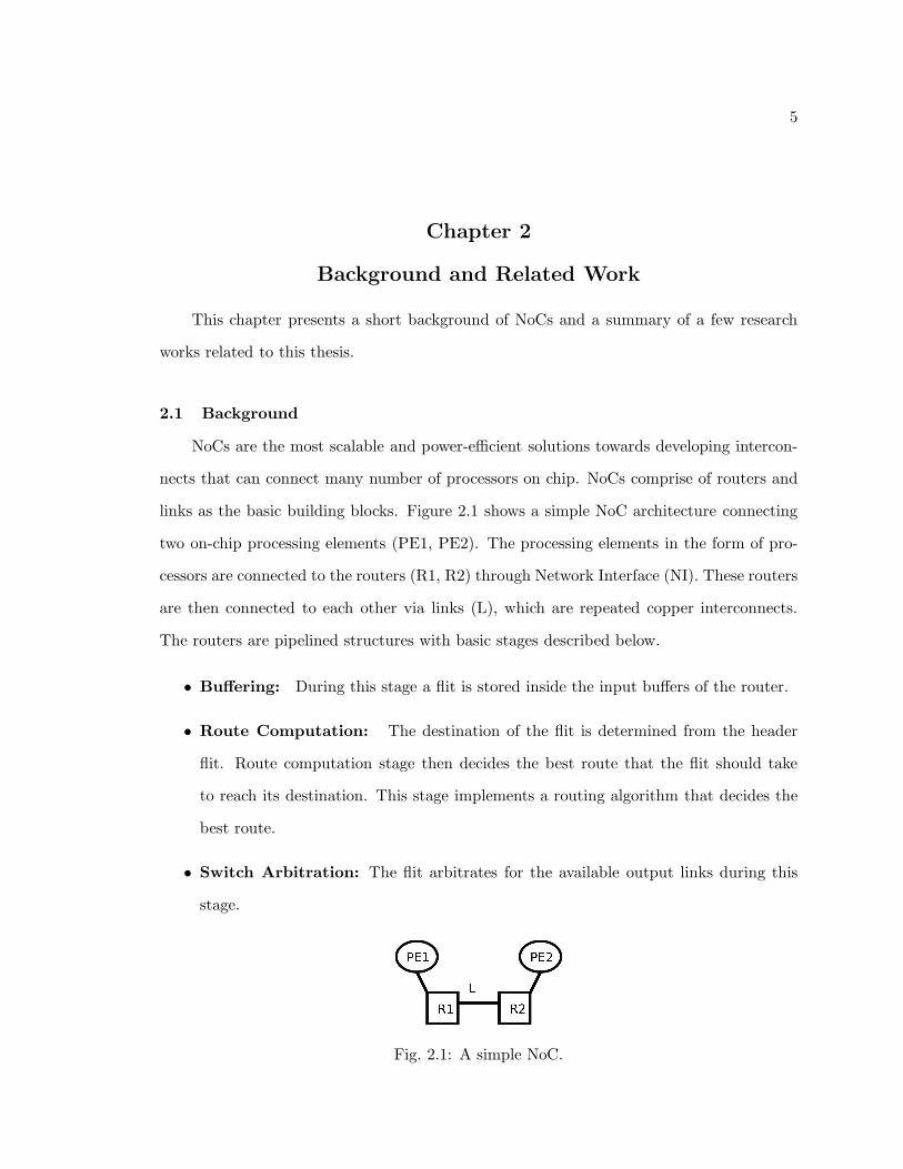
links as the basic building blocks. Figure 2.1 shows a simple NoC architecture connecting
two on-chip processing elements (PE1, PE2). The processing elements in the form of pro-
cessors are connected to the routers (R1, R2) through Network Interface (NI). These routers
are then connected to each other via links (L), which are repeated copper interconnects.
The routers are pipelined structures with basic stages described below.
• Buffering: During this stage a flit is stored inside the input buffers of the router.
• Route Computation: The destination of the flit is determined from the header
flit. Route computation stage then decides the best route that the flit should take
to reach its destination. This stage implements a routing algorithm that decides the
best route.
• Switch Arbitration: The flit arbitrates for the available output links during this
stage.
Fig. 2.1: A simple NoC.

6
• Switch Traversal: After the output link allocation, the flit traverses the crossbar to
reach the output buffers corresponding to the output link.
• Link Traversal: The final stage of the pipeline is the link traversal where the flit
traverses the output link towards the destination router.
As this work deals with the development of aging-aware routing algorithms, the back-
ground can be divided into two sections: (a) Routing algorithms, and (b) Aging issues.
2.1.1 Routing Algorithms
Routing algorithms are used to decide the best path that a flit will take to reach its
destination router. As the performance and power consumption of a network is dependent
on the paths that flits take (shortest or longest), routing algorithms play an important role
in controlling the power-performance characteristics. Routing algorithms can be divided
into the following categories.
• Oblivious Routing: In oblivious routing, the path is completely determined by
the source and destination address. This type of routing enables simple and faster
router designs. However, oblivious routing algorithms are not able to address various
runtime issues such as congestion.
• Adaptive Routing: In adaptive routing, the path is decided dynamically based on
the runtime conditions such as network congestion. This way, they are able to achieve
better performance as compared to the oblivious routing algorithms. However, the
downside is a more complex and costly adaptive router.
2.1.2 Aging Issues
This work addresses the following aging issues.
• Process Variations: Process variations (PV) are caused due to inability to control
the fabrication process at a smaller technology node. The key process parameters
affected by PV are the threshold voltage (Vth) and the effective channel length (Leff ).
7
Variation in Vth is considered to be extremely important as it directly affects the
frequency and leakage power of the device [11].
• NBTI: Negative Bias Temperature Instability (NBTI) is a phenomenon that causes
an instability of PMOS paramters (such as threshold voltage) under negative bias
and relatively high temperature. NBTI leads to formation of interface traps at the
Si/SiO2 interface by breaking the Si− H bonds, causing shifts in threshold voltage.
NBTI affects the frequency of operation of a circuit [12].
• Electromigration: With intensive technology scaling, electromigration has become
a major reliability problem for the interconnects. Reduction in wire widths due to
submicron dimensions causes very high current densities and temperature gradients.
Electromigration occurs when the current density is sufficiently high to cause the drift
of metal ions in the direction of the electron flow. These metal ions can cause voids
in the barrier layer of the wires, reducing the effective conducting area of the wire
and increasing its resistance. This can lead to an increase in the RC delay of the
interconnect [13].
2.2 Related Work
There has been considerable research in the field of routing algorithms for NoCs. Shafiee
et al. proposed an application aware deadlock free oblivious routing algorithm based on ex-
tended turn model, modeled using MILP [14]. Nikitin et al. have proposed a mathematical
formulation that simultaneously defines the topology of the system and the routes for the
traffic between routers [15].
Moreover with manufacturing defects and hardware malfunctions, contemporary re-
search is also directed towards fault-tolerant routing algorithms for NoCs. Shi et al. re-
cently proposed a scalable and distributed fault tolerant routing algorithm for NoCs that
divides the system into regions and each region gurantees fault-tolerance of its own area [16].
Fick et al. developed a highly resilient routing algorithm that reconfigures around the fault
components to improve robustness of the system [17]. Chaix et al. proposed a fault-tolerant
8
adaptive routing algorithm that is able to route packets in the presence of multiple nodes
and link failures without using routing tables [18]. Akbari et al. address the issue of poor
vertical links yield in case of 3D mesh-based many core ICs by introducing AFRA, a low cost
high performance deadlock-free routing algorithm that tolerates faults on vertical links [19].
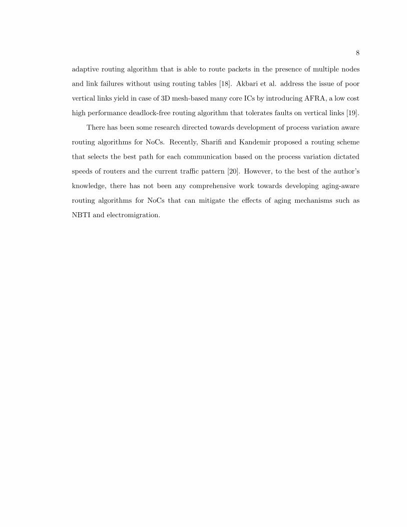
There has been some research directed towards development of process variation aware
routing algorithms for NoCs. Recently, Sharifi and Kandemir proposed a routing scheme
that selects the best path for each communication based on the process variation dictated
speeds of routers and the current traffic pattern [20]. However, to the best of the author’s
knowledge, there has not been any comprehensive work towards developing aging-aware
routing algorithms for NoCs that can mitigate the effects of aging mechanisms such as
NBTI and electromigration.
9
Chapter 3
Fault-Tolerance of NoCs
This chapter presents a brief robustness analysis of an NoC that not only considers
impact of aging on routers but also considers the effects of aging mechanisms such as NBTI
and electromigration on links.
3.1 The Experiment
To show the importance of considering the aging effects on links, an experiment is
performed using an NoC architecture that comprises two routers connected by two uni-
directional links. The flexible numerical model of NBTI degradation based on reaction-
diffusion [21] and wire resistance-based electromigration stress model [13] is used to model
aging in this experiment. Network latency is analyzed under four different degradation
schemes given by Table 3.1. These schemes are evaluated under tornado synthetic traf-
fic pattern for three different injection rates: (a) low (0.1 flits/cycle), (b) medium (0.3
flits/cycle), (c) high (0.5 flits/cycle).
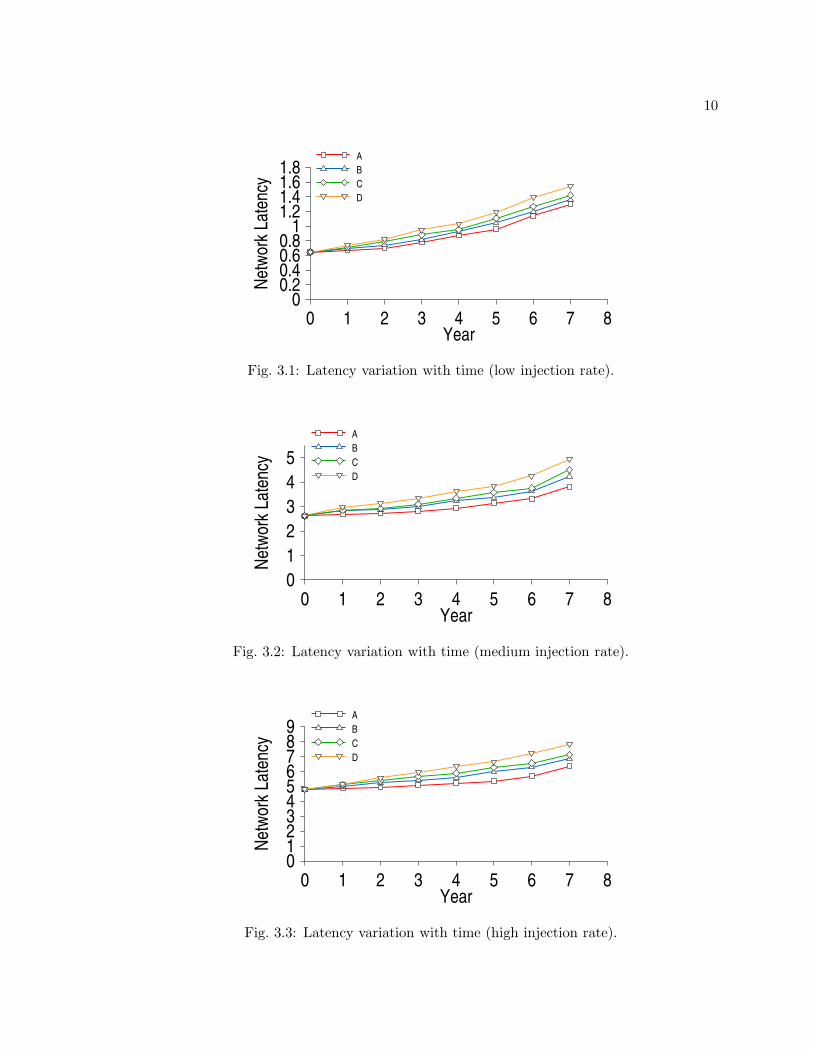
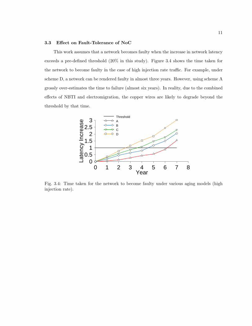
3.2 Analyzing Network Latency
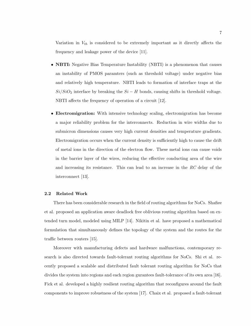
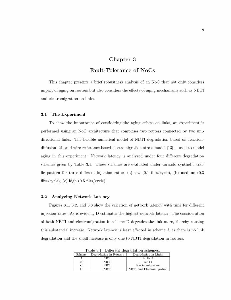
Figures 3.1, 3.2, and 3.3 show the variation of network latency with time for different
injection rates. As is evident, D estimates the highest network latency. The consideration
of both NBTI and electromigration in scheme D degrades the link more, thereby causing
this substantial increase. Network latency is least affected in scheme A as there is no link
degradation and the small increase is only due to NBTI degradation in routers.
Table 3.1: Different degradation schemes.Scheme Degradation in Routers Degradation in Links
A NBTI NONEB NBTI NBTIC NBTI ElectromigrationD NBTI NBTI and Electromigration
10
Year0 1 2 3 4 5 6 7 8
Net
wor
k La
tenc
y
00.20.40.60.8
11.21.41.61.8
A
B
C
D
Fig. 3.1: Latency variation with time (low injection rate).
Year0 1 2 3 4 5 6 7 8
Net
wor
k La
tenc
y
0
1
2
3
4
5
A
B
C
D
Fig. 3.2: Latency variation with time (medium injection rate).
Year0 1 2 3 4 5 6 7 8
Net
wor
k La
tenc
y
0123456789
A
B
C
D
Fig. 3.3: Latency variation with time (high injection rate).
11
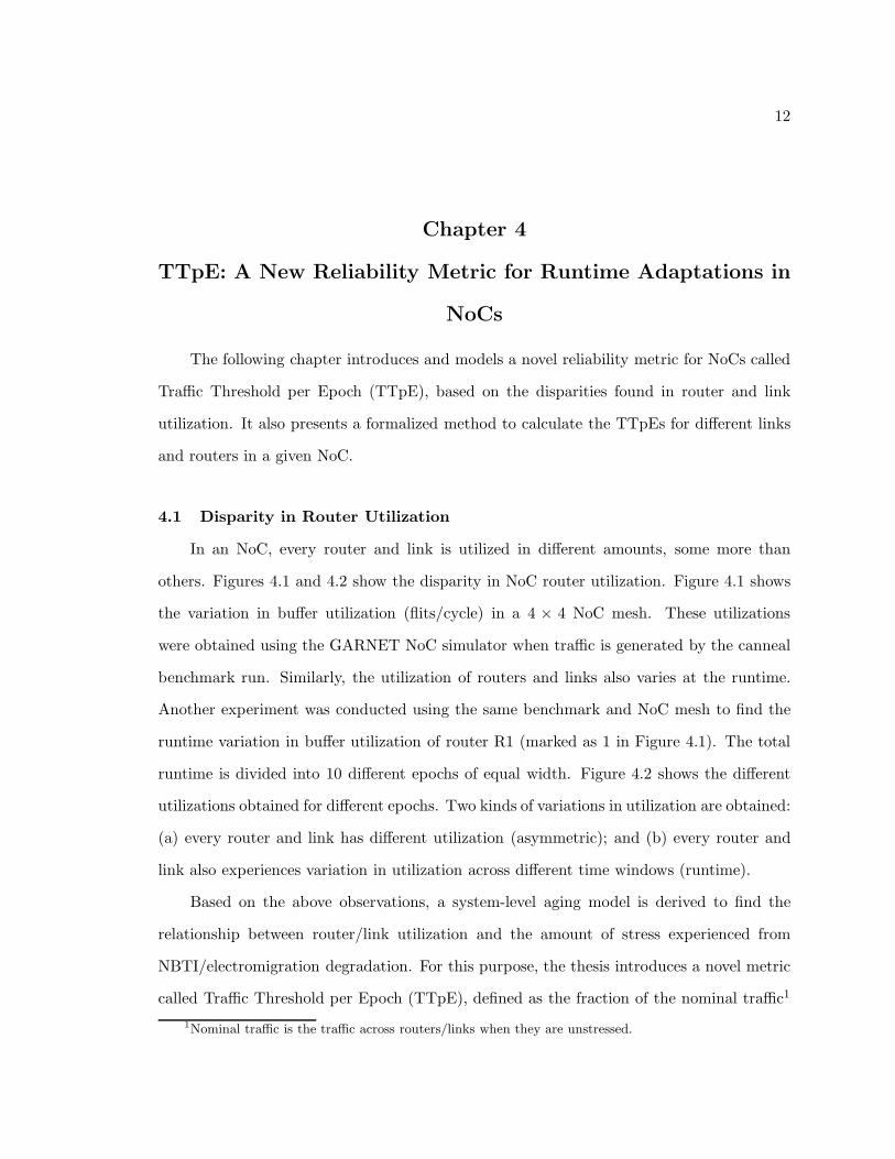
3.3 Effect on Fault-Tolerance of NoC
This work assumes that a network becomes faulty when the increase in network latency
exceeds a pre-defined threshold (20% in this study). Figure 3.4 shows the time taken for
the network to become faulty in the case of high injection rate traffic. For example, under
scheme D, a network can be rendered faulty in almost three years. However, using scheme A
grossly over-estimates the time to failure (almost six years). In reality, due to the combined
effects of NBTI and electromigration, the copper wires are likely to degrade beyond the
threshold by that time.
Year0 1 2 3 4 5 6 7 8
Late
ncy
Incr
ease
00.5
11.5
22.5
3ThresholdABCD
Fig. 3.4: Time taken for the network to become faulty under various aging models (highinjection rate).
12
Chapter 4
TTpE: A New Reliability Metric for Runtime Adaptations in
NoCs
The following chapter introduces and models a novel reliability metric for NoCs called
Traffic Threshold per Epoch (TTpE), based on the disparities found in router and link
utilization. It also presents a formalized method to calculate the TTpEs for different links
and routers in a given NoC.
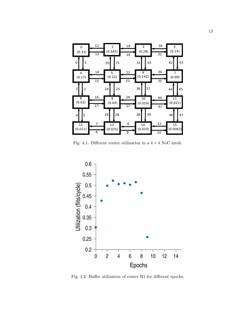
4.1 Disparity in Router Utilization
In an NoC, every router and link is utilized in different amounts, some more than
others. Figures 4.1 and 4.2 show the disparity in NoC router utilization. Figure 4.1 shows
the variation in buffer utilization (flits/cycle) in a 4 × 4 NoC mesh. These utilizations
were obtained using the GARNET NoC simulator when traffic is generated by the canneal
benchmark run. Similarly, the utilization of routers and links also varies at the runtime.
Another experiment was conducted using the same benchmark and NoC mesh to find the
runtime variation in buffer utilization of router R1 (marked as 1 in Figure 4.1). The total
runtime is divided into 10 different epochs of equal width. Figure 4.2 shows the different
utilizations obtained for different epochs. Two kinds of variations in utilization are obtained:
(a) every router and link has different utilization (asymmetric); and (b) every router and
link also experiences variation in utilization across different time windows (runtime).
Based on the above observations, a system-level aging model is derived to find the
relationship between router/link utilization and the amount of stress experienced from
NBTI/electromigration degradation. For this purpose, the thesis introduces a novel metric
called Traffic Threshold per Epoch (TTpE), defined as the fraction of the nominal traffic1
1Nominal traffic is the traffic across routers/links when they are unstressed.
13
Fig. 4.1: Different router utilization in a 4 × 4 NoC mesh.
Epochs
0 2 4 6 8 10 12 14
Util
izat
ion
(flit
s/cy
cle)
0.2
0.25
0.3
0.35
0.4
0.45
0.5
0.55
0.6
Fig. 4.2: Buffer utilization of router R1 for different epochs.
14
that a stressed router/link should accept during a particular epoch.
The significance of using TTpE as a reliability metric for an aging-stressed NoC design
lies in the following facts.
• It determines an upper limit on the amount of traffic that a router or link should
accept so as to keep the variation in network latency below a pre-defined threshold
for a particular aging period (7 years in this work). If the limit imposed by TTpE is
exceeded in a router undergoing maximum degradation, it will be rendered faulty.
• TTpEs are derived from continuous monitoring of the traffic, and are used to adapt
the routing policies for every epoch to mitigate the long-term degradation in the NoC.
The aging model for routers and links is described next.
4.2 Modeling Aging Impact on NoC Routers and Links
This section presents the system-level aging model that models the impact of aging
mechanisms such as NBTI and electromigration on NoC routers and links. The section
also presents a derivation of the dependency of TTpE of stressed links and routers on the
aging-induced delay variation.
4.2.1 Modeling Delay Variations Due to NBTI Degradation in NoC Routers
Due to the presence of both combinational and storage circuitry in NoC routers, the
effects of NBTI on the performance of these routers cannot be ignored [2]. These effects
are modeled using the flexible numerical model of NBTI degradation based on reaction-
diffusion [21]. According to this model, Vth shift is given by
∆Vth =qNit(t)
Cox, (4.1)
where q is the elementary charge, Nit(t) is the number of interface traps per unit area at
time t, and Cox is the PMOS gate capacitance. This model calculates Nit(t) using the
different parameters mentioned in Table 4.1.
15
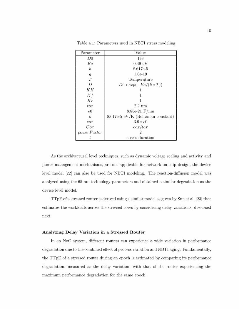
Table 4.1: Parameters used in NBTI stress modeling.
Parameter Value
D0 1e8Ea 0.49 eVk 8.617e-5q 1.6e-19T TemperatureD D0 ∗ exp(−Ea/(k ∗ T ))
KH 1Kf 1Kr 1tox 2.2 nme0 8.85e-21 F/nmk 8.617e-5 eV/K (Boltzman constant)
eox 3.9 ∗ e0Cox eox/tox
powerFactor 2t stress duration
As the architectural level techniques, such as dynamic voltage scaling and activity and
power management mechanisms, are not applicable for network-on-chip design, the device
level model [22] can also be used for NBTI modeling. The reaction-diffusion model was
analyzed using the 65 nm technology parameters and obtained a similar degradation as the
device level model.
TTpE of a stressed router is derived using a similar model as given by Sun et al. [23] that
estimates the workloads across the stressed cores by considering delay variations, discussed
next.
Analyzing Delay Variation in a Stressed Router
In an NoC system, different routers can experience a wide variation in performance
degradation due to the combined effect of process variation and NBTI aging. Fundamentally,
the TTpE of a stressed router during an epoch is estimated by comparing its performance
degradation, measured as the delay variation, with that of the router experiencing the
maximum performance degradation for the same epoch.
16
To estimate the delay variation in a stressed router, gate delay model given by Chang
and Sapatnekar [24] is extended to the critical path delay model. After perturbing Vth as
Vth = Vth0 + ∆Vth, the i-th critical path delay can be written as
di = di(Vth0, Leff ) +
(
δdi
δVth
)
∆Vth, (4.2)
where delay di(Vth0, Leff ) is modeled as a Gaussian distribution with Vth0 and Leff as the
nominal threshold voltage and channel length. As there can be many critical paths in a
single router, the critical path with the biggest variation is used in the calculation of TTpE.
All the routers in the system are analyzed to estimate their biggest critical path variation.
For a particular epoch, the TTpE of a given router is estimated by comparing its delay
variation with that of the router with the worst variation. However, in case the worst
router experiences more than 3σdelayrvariation, which statistically covers 99.7% of all delay
variations in the system [25], the 3σdelayrvariation is only used for the TTpE estimation.
∆dr = min(maxi((δdi/δVth)∆Vth), 3σdelayr) (4.3)
The percentage model proposed by Sun et al. [23] is used to relate the delay variation with
TTpE. According to this model, when the delay has zero variation, the value of TTpE is
100% and when the delay variation is maximum (at 3σdelayr), the router must not accept
any traffic (TTpE = 0). Hence, the Traffic Threshold per Epoch of the stressed router due
to delay variation is given by
TTpEr = 1 −
(
∆dr
3σdelayr
)
. (4.4)
A similar approach is used to model TTpE of NoC links next.
4.2.2 Modeling Delay Variations Due to NBTI and Electromigration Degra-
dations in NoC Links
NoC links are modeled as repeated copper interconnects and therefore suffer from two
17
different types of stresses: (a) NBTI stress that increases the repeater resistance [26], and
(b) electromigration stress due to the use of barrier layers in copper interconnects that
increases the wire resistance [13].
Analyzing Delay Variation in Stressed Links
The propagation delay of a repeated interconnect in the presence of NBTI and electro-
migration stress is modeled by including the increase in wire resistance due to electromi-
gration in the NBTI-aware delay model proposed by Datta and Burleson [26]. Therefore,
the propagation delay of the link under both NBTI and electromigration is
dls = kTd + p(0.69)
(
Cd +Cw
k+ Cg
)
∆Ro
+p(0.69)
(
Cg
k
)
∆Rw + p(0.38)
(
Cw
k2
)
∆Rw,
(4.5)
where k is the number of repeaters, Ro is the repeater resistance, Cd is the output drain
diffusion capacitance of the repeater, Cg is the input gate capacitance of the repeater, Rw is
the wire resistance, Cw is the wire capacitance, p is the number of stressed repeaters, Td is
the original unstressed delay, ∆Ro is the increase in repeater resistance due to NBTI, and
∆Rw is the increase in wire resistance due to electromigration.
The variability of repeater resistance with the threshold voltage (∆Vth) due to NBTI
is given as [26]
δRo
δVth
= g
[
2 + (VGS − |Vth| − ∆Vth)( µ2.vsat.L
+ θ)12µCox
WL
(VGS − |Vth| − ∆Vth)3
]
, (4.6)
where
g =3
4Vdd
(
1 −7
9λVdd
)
. (4.7)
∆Vth is given by Equation (4.1) and rest of the symbols are similar to those used by Datta
and Burleson [26].
The variability of the wire resistance due to electromigration stress is modeled as [13]
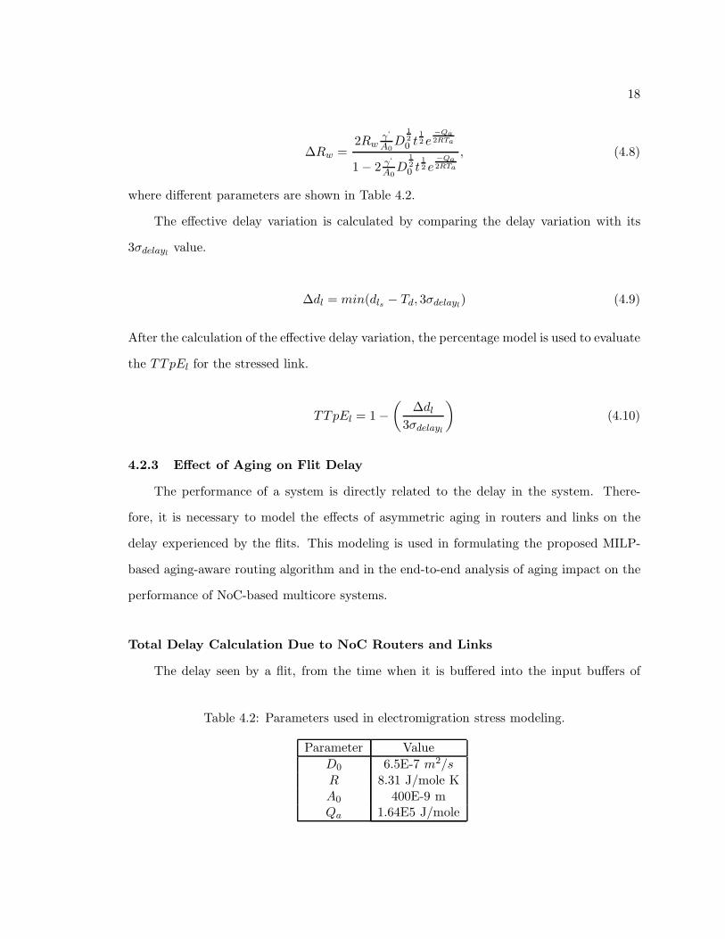
18
∆Rw =2Rw
γ‘
A0D
1
2
0 t1
2 e−Qa2RTa
1 − 2 γ‘
A0D
1
2
0 t1
2 e−Qa2RTa
, (4.8)
where different parameters are shown in Table 4.2.
The effective delay variation is calculated by comparing the delay variation with its
3σdelaylvalue.
∆dl = min(dls − Td, 3σdelayl) (4.9)
After the calculation of the effective delay variation, the percentage model is used to evaluate
the TTpEl for the stressed link.
TTpEl = 1 −
(
∆dl
3σdelayl
)
(4.10)
4.2.3 Effect of Aging on Flit Delay
The performance of a system is directly related to the delay in the system. There-
fore, it is necessary to model the effects of asymmetric aging in routers and links on the
delay experienced by the flits. This modeling is used in formulating the proposed MILP-
based aging-aware routing algorithm and in the end-to-end analysis of aging impact on the
performance of NoC-based multicore systems.
Total Delay Calculation Due to NoC Routers and Links
The delay seen by a flit, from the time when it is buffered into the input buffers of
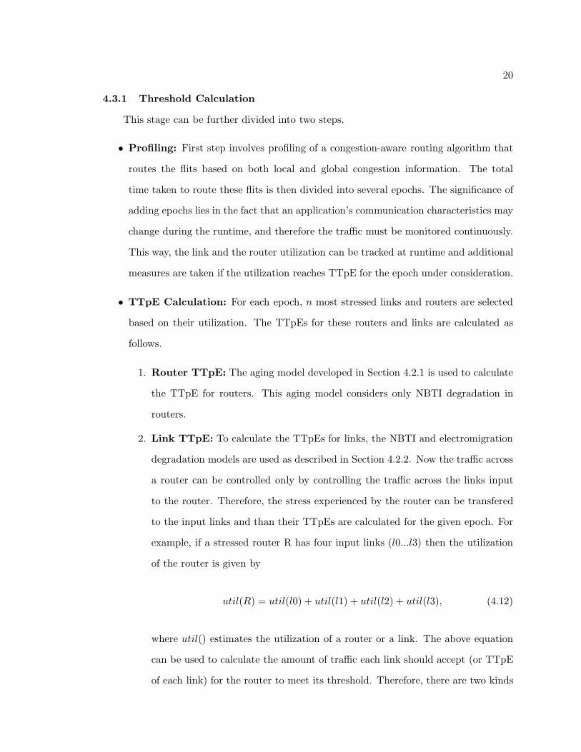
Table 4.2: Parameters used in electromigration stress modeling.
Parameter Value
D0 6.5E-7 m2/sR 8.31 J/mole KA0 400E-9 mQa 1.64E5 J/mole
19
an NoC Router till it is allocated an output link can be described as the delay due to an
unstressed NoC router or drus. Similarly the unstressed delay due to an NoC link can be
defined as the time taken by a flit to travel the link to reach the router at the other end or
dlus. Now if a router/link is under aging stress, the same flit will experience a higher delay
as signified by Equations (4.2) and (4.5). Therefore, the delay due to a stressed router and
link can be formulated as
drs = drus + ∆dr; dls = dlus + ∆dl, (4.11)
where ∆dr is given by ∆delayr in Equation (4.3) and ∆dl is given by ∆delayl in Equa-
tion (4.9). ∆dr and ∆dl for different routers and links will be different based on their
utilization.
The TTpEs vary over the runtime with different values during different epochs for each
stressed router and link. In order to calculate these thresholds, a congestion-aware routing
algorithm is first profiled to estimate the router/link utilization for every epoch during
runtime. Depending on the utilization, TTpEs are calculated for the stressed routers and
links for every epoch using the system-level aging model. TTpEs are then stored in each
router in the form of lookup tables so that the router can select the appropriate threshold
depending on the epoch during runtime. These steps are discussed in more details next.
4.3 TTpE Calculation
The calculation of TTpE involves the following stages.
• Threshold Calculation: This stage mainly involves profiling of a state-of-the-art
congestion-aware routing algorithm [27] to calculate the TTpE of different stressed
links and routers.
• Using TTpE Estimation in Routing: During this stage, the traffic threshold
tables are built, which are then stored inside each router.
These stages are discussed in more detail next.
20
4.3.1 Threshold Calculation
This stage can be further divided into two steps.
• Profiling: First step involves profiling of a congestion-aware routing algorithm that
routes the flits based on both local and global congestion information. The total
time taken to route these flits is then divided into several epochs. The significance of
adding epochs lies in the fact that an application’s communication characteristics may
change during the runtime, and therefore the traffic must be monitored continuously.
This way, the link and the router utilization can be tracked at runtime and additional
measures are taken if the utilization reaches TTpE for the epoch under consideration.
• TTpE Calculation: For each epoch, n most stressed links and routers are selected
based on their utilization. The TTpEs for these routers and links are calculated as
follows.
1. Router TTpE: The aging model developed in Section 4.2.1 is used to calculate
the TTpE for routers. This aging model considers only NBTI degradation in
routers.
2. Link TTpE: To calculate the TTpEs for links, the NBTI and electromigration
degradation models are used as described in Section 4.2.2. Now the traffic across
a router can be controlled only by controlling the traffic across the links input
to the router. Therefore, the stress experienced by the router can be transfered
to the input links and than their TTpEs are calculated for the given epoch. For
example, if a stressed router R has four input links (l0...l3) then the utilization
of the router is given by
util(R) = util(l0) + util(l1) + util(l2) + util(l3), (4.12)
where util() estimates the utilization of a router or a link. The above equation
can be used to calculate the amount of traffic each link should accept (or TTpE
of each link) for the router to meet its threshold. Therefore, there are two kinds
21
of stressed links: (a) links that are directly under aging stress, and (b) input
links that experience stress because of the stressed router.
4.3.2 Using TTpE Estimation in Routing
Here, the computed TTpEs for different epochs are stored in the form of lookup tables
(SLset) inside each router. The router at runtime can then select the appropriate TTpE
depending on the epoch. During this stage, the routing tables are also populated for each
router. In order to minimize network latency and communication energy, only the deadlock-
free shortest paths are selected for each flow.
22
Chapter 5
Aging-Aware Adaptive Routing Algorithm
This chapter presents a robust aging-aware routing algorithm that not only reduces
the stress experienced by heavily utilized NoC components, but also minimizes the overall
aging induced power-performance overheads.
5.1 Algorithm
The algorithm involves the following two stages (Table 5.1).
• Congestion and Aging-Aware Routing: For each flow at runtime, the routing
algorithm selects the best shortest path from the routing table that (a) suffers from
least aging degradation, i.e., the path that suffers from least delay variation due to
aging (1-a); and (b) is least congested (1-b). A higher priority is given to a path that
is least degraded as compared to a path with the least congestion. For example, in
case of an arbitrary flow F , if the available number of deadlock-free shortest paths is
four (path0....path3) then the algorithm maintains congestion and aging scores (sccong
and scage) for each of these paths. These scores are calculated based on both local
and global aging and congestion information obtained from different routers and links
present in the paths. Now if the scage is least for path0 but sccong is least for path3
then the algorithm selects path0 for routing. In a different situation, if scage is same
for all paths but sccong is least for path3 then path3 is only selected for routing.
• Honoring TTpE by Employing Recovery Cycles: During the execution of the
routing algorithm, each stressed link in SLset is checked to see if it meets its respective
TTpE for every epoch (2-a). There can be two possible cases: (a) In the epoch, if
the link has already reached its TTpE, then the link must be kept idle for the rest
of the epoch so that its utilization does not exceed its TTpE; and (b) If the link
23
Table 5.1: Algorithm for aging-aware adaptive routing.ALGORITHM Aging Adaptive:For each flow,
1. Select the best shortest path from the routingtable which:
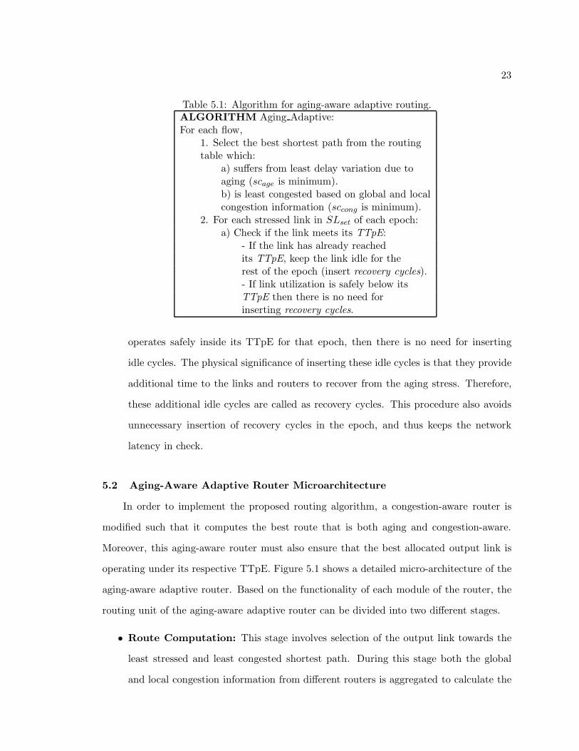
a) suffers from least delay variation due toaging (scage is minimum).b) is least congested based on global and localcongestion information (sccong is minimum).
2. For each stressed link in SLset of each epoch:a) Check if the link meets its TTpE:
- If the link has already reachedits TTpE, keep the link idle for therest of the epoch (insert recovery cycles).- If link utilization is safely below itsTTpE then there is no need forinserting recovery cycles.
operates safely inside its TTpE for that epoch, then there is no need for inserting
idle cycles. The physical significance of inserting these idle cycles is that they provide
additional time to the links and routers to recover from the aging stress. Therefore,
these additional idle cycles are called as recovery cycles. This procedure also avoids
unnecessary insertion of recovery cycles in the epoch, and thus keeps the network
latency in check.
5.2 Aging-Aware Adaptive Router Microarchitecture
In order to implement the proposed routing algorithm, a congestion-aware router is
modified such that it computes the best route that is both aging and congestion-aware.
Moreover, this aging-aware router must also ensure that the best allocated output link is
operating under its respective TTpE. Figure 5.1 shows a detailed micro-architecture of the
aging-aware adaptive router. Based on the functionality of each module of the router, the
routing unit of the aging-aware adaptive router can be divided into two different stages.
• Route Computation: This stage involves selection of the output link towards the
least stressed and least congested shortest path. During this stage both the global
and local congestion information from different routers is aggregated to calculate the
24
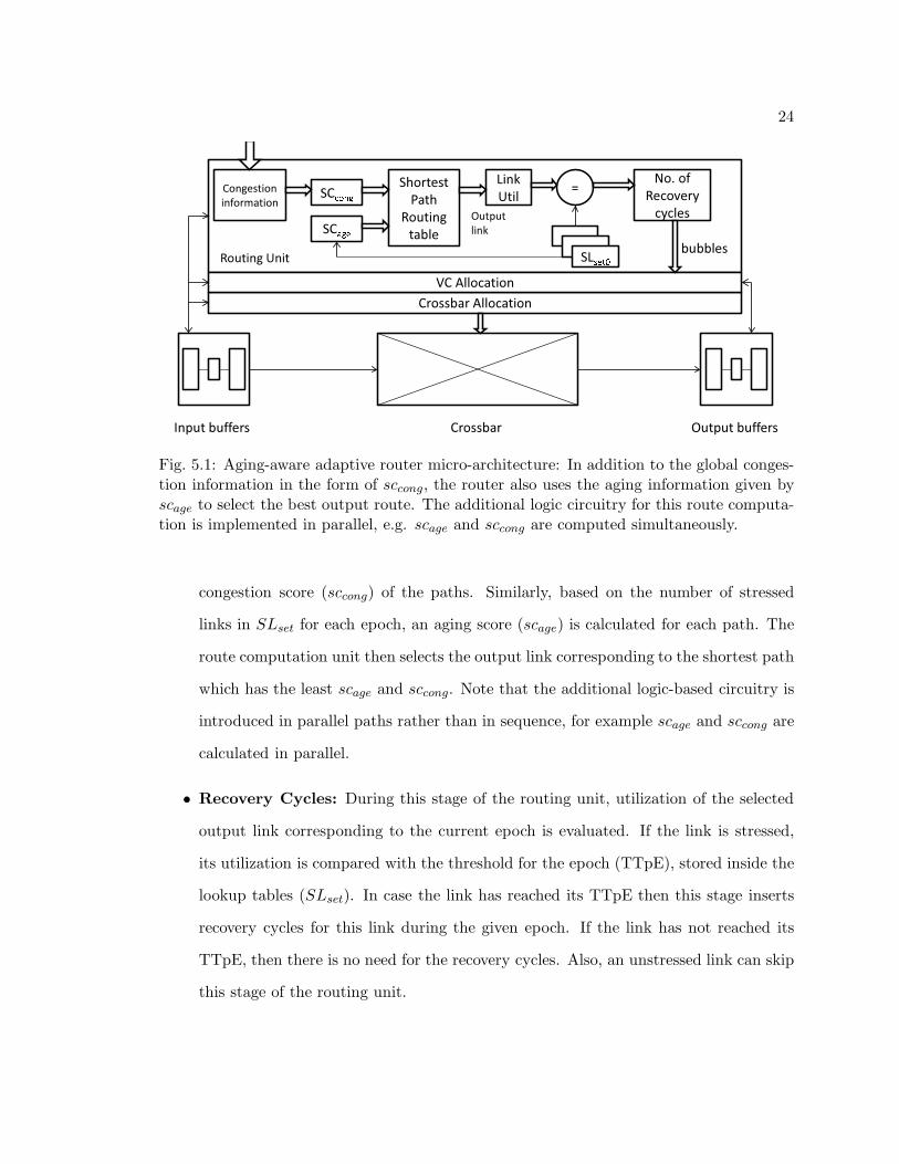
Fig. 5.1: Aging-aware adaptive router micro-architecture: In addition to the global conges-tion information in the form of sccong, the router also uses the aging information given byscage to select the best output route. The additional logic circuitry for this route computa-tion is implemented in parallel, e.g. scage and sccong are computed simultaneously.
congestion score (sccong) of the paths. Similarly, based on the number of stressed
links in SLset for each epoch, an aging score (scage) is calculated for each path. The
route computation unit then selects the output link corresponding to the shortest path
which has the least scage and sccong. Note that the additional logic-based circuitry is
introduced in parallel paths rather than in sequence, for example scage and sccong are
calculated in parallel.
• Recovery Cycles: During this stage of the routing unit, utilization of the selected
output link corresponding to the current epoch is evaluated. If the link is stressed,
its utilization is compared with the threshold for the epoch (TTpE), stored inside the
lookup tables (SLset). In case the link has reached its TTpE then this stage inserts
recovery cycles for this link during the given epoch. If the link has not reached its
TTpE, then there is no need for the recovery cycles. Also, an unstressed link can skip
this stage of the routing unit.
25
5.3 Experimental Methodology
The experimental methodology combines SPICE level analysis for process variation
and NBTI aging, statistical timing analysis using synthesized verilog for NoC routers, and
full system architectural simulation. The effect of process variation and NBTI aging in
basic logic gates are performed through synopsys HSPICE, using Predictive Technology
Models (PTM), and long term degradation due to NBTI [22]. On each of these gates,
10K Monte Carlo simulation runs are used to obtain respective statistical distributions
of their performance characteristics. These gates at the 45 nm technology are then used
to synthesize the NoC router RTL obtained from Stanford University’s open-source NoC
router resources [28]. Subsequently a statistical timing analysis is performed to find various
critical paths in the router, and their delay distributions under the combined effect of process
variation and NBTI aging.
Architectural simulation is carried out using GARNET NoC simulator, embedded in-
side GEMS [29]. GARNET uses the ORION power model [30] to calculate power con-
sumptions of the routers and the links. Experimental setup consists of a system with 16
processors in a 4×4 mesh topology. Each processor has a dual issue 32 entry out-of-order is-
sue window and a private L1 cache (2-way, 32 KB, response latency: 3 cycles); and a shared
L2 cache (4-way, 2 MB, response latency: 15 cycles). For traffic generation and system-level
analysis, PARSEC benchmarks with 16 threads pinned to cores are used: Canneal (can),
Dedup (ded), Facesim (fac), Ferret (fer), Fluidanimate (flu), Freqmine (fre), and Raystone
(ray).
5.4 Experimental Results
To study the power-performance impact of aging on NoC designs, a set of experiments
are conducted on a 4 × 4 NoC mesh shown in Figure 4.1. Different schemes implemented
for comparison are discussed next.
26
5.4.1 Comparative Schemes
Three different schemes are used to show the importance of a robust aging-aware adap-
tive routing algorithm.
• RCA-1D: This scheme uses a state-of-the-art congestion-aware routing algorithm to
route the flits in an NoC system comprising aging-stressed routers and links. Without
aging awareness, this scheme continues to use heavily degraded links/routers, thereby
incurring power-performance overhead. Delay degradations in the stressed routers
and links are modeled according to Section 4.2.
• AGE-ADAP: Here the proposed congestion and aging-aware adaptive routing algo-
rithm is implemented to route flits in a stressed NoC design. This scheme employs the
step 1 of the proposed routing algorithm (Section 5.1), but does not honor the TTpE
limits and therefore does not insert any recovery cycles in the epochs during runtime.
Delay variation in the routers and links are based on the model in Section 4.2.
• AGE-ADAP-REC: This scheme extends AGE-ADAP such that it inserts recovery
cycles for stressed links/routers during an epoch if the utilization has reached TTpE.
Therefore, this scheme ensures that none of the stressed routers/links operates beyond
their calculated TTpE.
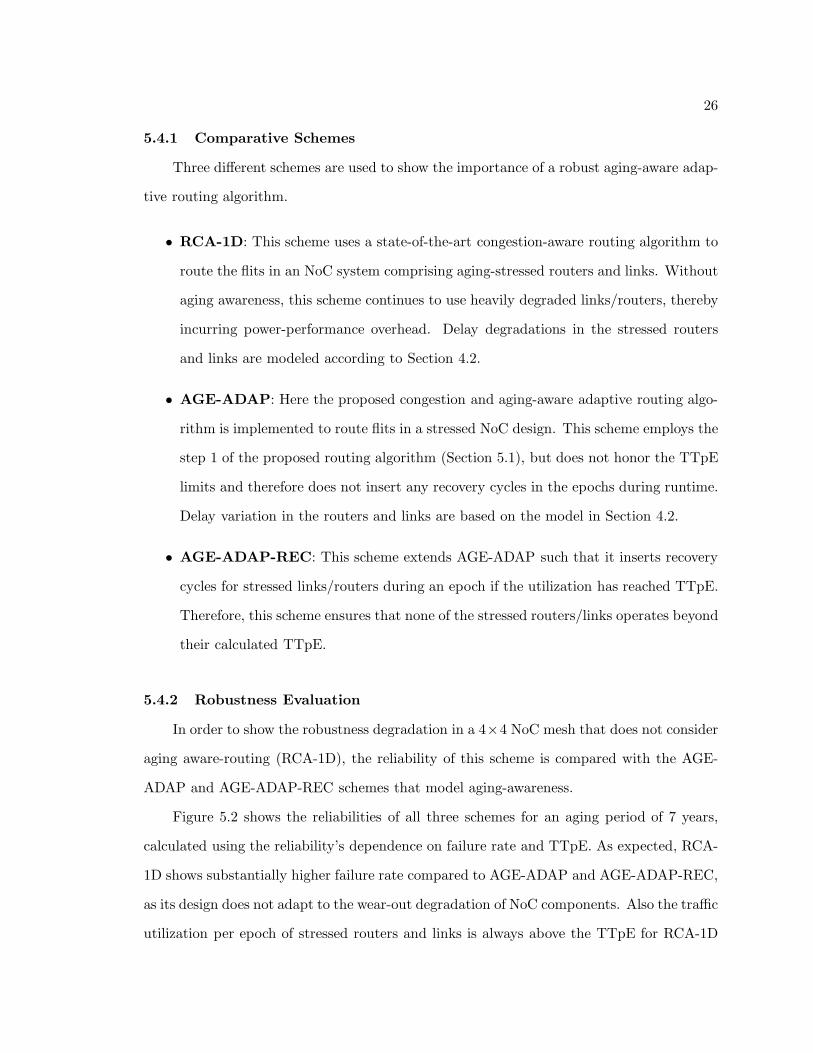
5.4.2 Robustness Evaluation
In order to show the robustness degradation in a 4×4 NoC mesh that does not consider
aging aware-routing (RCA-1D), the reliability of this scheme is compared with the AGE-
ADAP and AGE-ADAP-REC schemes that model aging-awareness.
Figure 5.2 shows the reliabilities of all three schemes for an aging period of 7 years,
calculated using the reliability’s dependence on failure rate and TTpE. As expected, RCA-
1D shows substantially higher failure rate compared to AGE-ADAP and AGE-ADAP-REC,
as its design does not adapt to the wear-out degradation of NoC components. Also the traffic
utilization per epoch of stressed routers and links is always above the TTpE for RCA-1D
27
Year0 1 2 3 4 5 6 7 8
Mes
h R
elia
bilit
y0
0.20.40.60.8
11.2 AGE−ADAP−REC AGE−ADAP RCA−1D
Fig. 5.2: NoC robustness degradation over time.
which further reduces its reliability. As stressed routers and links are well below their TTpE
limits in AGE-ADAP-REC, its reliability is even better than AGE-ADAP.
5.4.3 Overhead Analysis
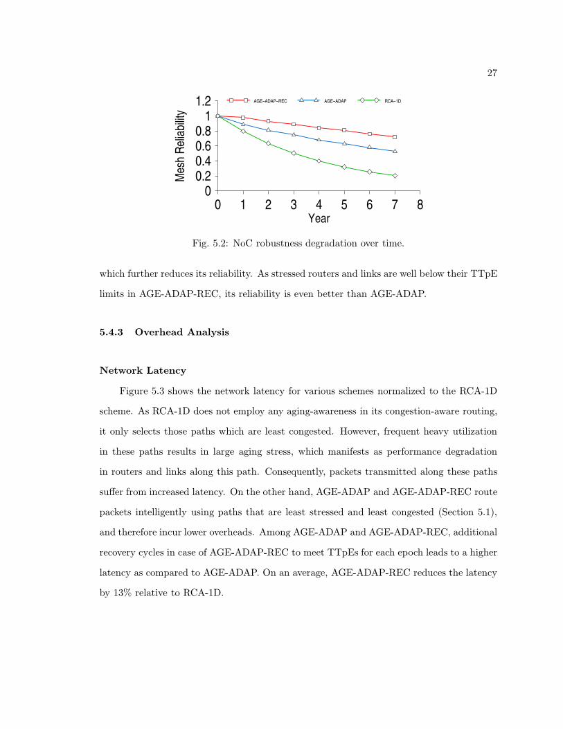
Network Latency
Figure 5.3 shows the network latency for various schemes normalized to the RCA-1D
scheme. As RCA-1D does not employ any aging-awareness in its congestion-aware routing,
it only selects those paths which are least congested. However, frequent heavy utilization
in these paths results in large aging stress, which manifests as performance degradation
in routers and links along this path. Consequently, packets transmitted along these paths
suffer from increased latency. On the other hand, AGE-ADAP and AGE-ADAP-REC route
packets intelligently using paths that are least stressed and least congested (Section 5.1),
and therefore incur lower overheads. Among AGE-ADAP and AGE-ADAP-REC, additional
recovery cycles in case of AGE-ADAP-REC to meet TTpEs for each epoch leads to a higher
latency as compared to AGE-ADAP. On an average, AGE-ADAP-REC reduces the latency
by 13% relative to RCA-1D.
28
can ded fac fer flu fre ray
Nor
mal
ized
Lat
ency
0.6
0.7
0.8
0.9
1
1.1
RCA−1D AGE−ADAP AGE−ADAP−REC
Fig. 5.3: Normalized network latency (lower is better).
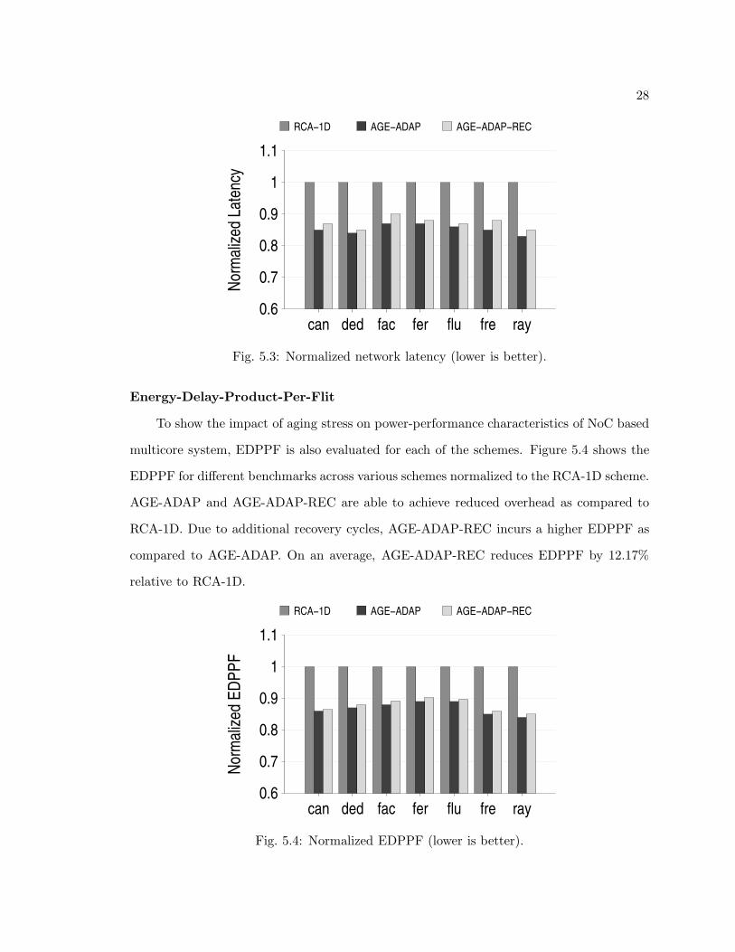
Energy-Delay-Product-Per-Flit
To show the impact of aging stress on power-performance characteristics of NoC based
multicore system, EDPPF is also evaluated for each of the schemes. Figure 5.4 shows the
EDPPF for different benchmarks across various schemes normalized to the RCA-1D scheme.
AGE-ADAP and AGE-ADAP-REC are able to achieve reduced overhead as compared to
RCA-1D. Due to additional recovery cycles, AGE-ADAP-REC incurs a higher EDPPF as
compared to AGE-ADAP. On an average, AGE-ADAP-REC reduces EDPPF by 12.17%
relative to RCA-1D.
can ded fac fer flu fre ray
Nor
mal
ized
ED
PP
F
0.6
0.7
0.8
0.9
1
1.1
RCA−1D AGE−ADAP AGE−ADAP−REC
Fig. 5.4: Normalized EDPPF (lower is better).
29
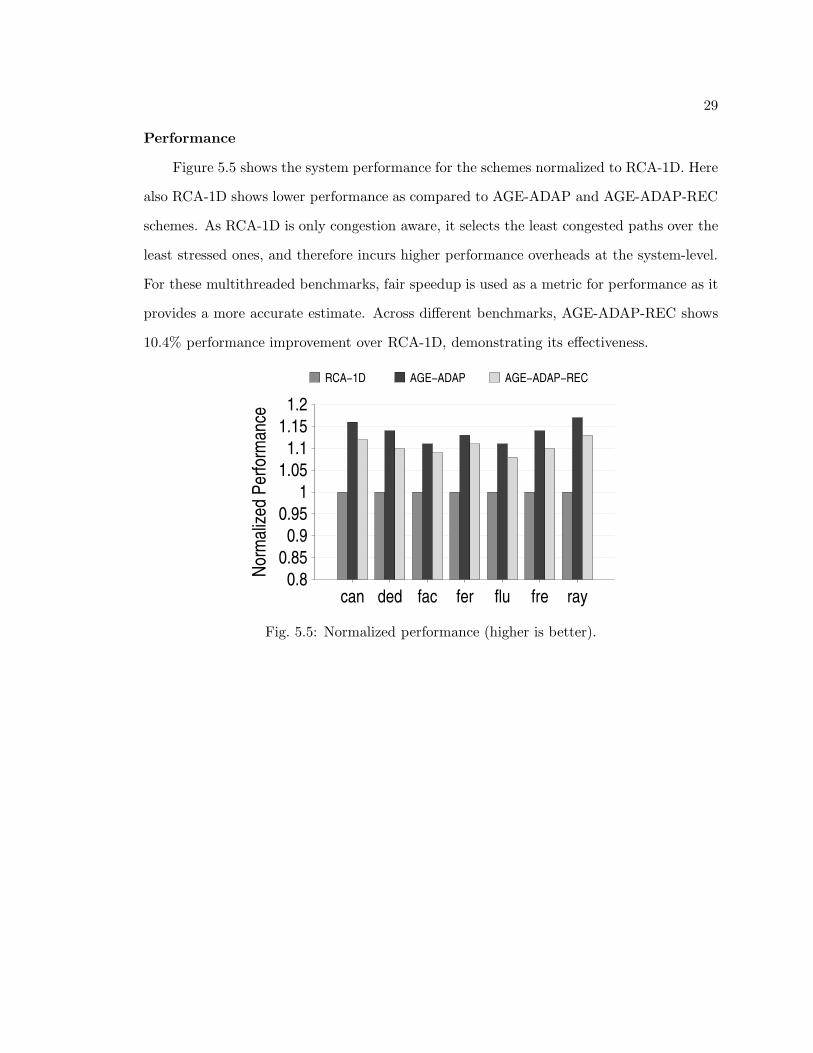
Performance
Figure 5.5 shows the system performance for the schemes normalized to RCA-1D. Here
also RCA-1D shows lower performance as compared to AGE-ADAP and AGE-ADAP-REC
schemes. As RCA-1D is only congestion aware, it selects the least congested paths over the
least stressed ones, and therefore incurs higher performance overheads at the system-level.
For these multithreaded benchmarks, fair speedup is used as a metric for performance as it
provides a more accurate estimate. Across different benchmarks, AGE-ADAP-REC shows
10.4% performance improvement over RCA-1D, demonstrating its effectiveness.
can ded fac fer flu fre ray
Nor
mal
ized
Per
form
ance
0.8
0.85
0.9
0.95
1
1.05
1.1
1.15
1.2
RCA−1D AGE−ADAP AGE−ADAP−REC
Fig. 5.5: Normalized performance (higher is better).
30
Chapter 6
MILP-Based Aging-Aware Oblivious Routing Algorithm
The following chapter outlines a routing algorithm that mitigates aging effects on NoC-
based multicore system performance with minimal overhead. Simply meeting TTpE limits
can substantially improve NoC reliability, but comes at a high cost of other design con-
straints. To effectively perform a multi-objective design space exploration, an optimization
framework based on MILP is used to formulate an aging-aware oblivious routing.
As oblivious routing algorithms statically determine deadlock-free shortest paths be-
tween given source-destination pairs, a design time variant of TTpE called as Traffic Ac-
ceptance Capacity (TAC) is used, described next.
6.1 Traffic Acceptance Capacity
In order to make sure that the stressed routers and links are not utilized above a par-
ticular threshold, the proposed MILP-based oblivious routing algorithm uses a design time
variant of TTpE metric for each router and link. Traffic Acceptance Capacity (TAC) can be
defined at the design time as the fraction of nominal traffic that a stressed link/router should
accept to avoid aging induced faults. For the purpose of TAC calculations, a single epoch
is only assumed with the epoch length equal to total runtime. The TAC limits imposed on
stressed routers and links at design time are given by TACr and TACl, respectively.
6.2 Algorithm
In this algorithm, router and link utilization are computed during the traffic profiling
stage. Various modules associated with the MILP-based routing algorithm are described
next.

31
6.2.1 Traffic Threshold Calculation
In order to control traffic across a stressed router, traffic flowing through the links that
input to the router must be controlled. For example, if router R5 in Figure 4.1 is stressed,
then the traffic across the input links (L15, L21, L22, L24) must be controlled such that R5
meets its TAC limit.
Therefore, the input links to a stressed router, whether stressed or unstressed, must
have an upper bound on the traffic that they can accept. In the case of stressed input links,
this bound should be less than or equal to their TACl limits.
6.2.2 Variable Definitions
These are the various variables used in the MILP.
• Variable to indicate the flow of flits.
F k: flow between some (source, destination) pair (s, d).
• Variable to indicate the amount of flits flowing through a link due to some flow.
FLkj : Amount of flits flowing through a link j due to flow F k, measured in flits.
P kj : Amount of flits flowing through a link j due to flow F k, measured in flits/cycle
(link utilization).
• Variable to show if a link j is utilized for flow F k.
Ukj =
1 if FLkj > 0
0 if FLkj = 0
• Variables to indicate the set of input links (I(R)) and the set of output links (O(R))
for a router R.
• Variables to indicate the total number of flits that comprise a flow F k (capacity of
flow), Ck, and total number of flits across all flows, TC.

32
• Variable to indicate the total number of hops for Fk.
hpk =∑
j∈LT
Ukj − 1
• Variable to formulate total delay across all the links. The delay-per-flit across the
stressed and unstressed links is used, as described in Section 4.2.3.
TLD =∑
k∈Tf
∑
j∈LT
FLkj ∗ dlj ,
where Tf represents all flows in the network and dlj is the delay-per-flit of link j:
dlj =
dlusj if j ∈ LT − Lstress
dlsj if j ∈ Lstress.
• Variable to show if a router i is utilized for a flow Fk.
rki =
1 if∑
j∈O(i) Ukj = 1
0 if∑
j∈O(i) Ukj = 0
• Variable for delay across all the routers. Here also delay-per-flit across the stressed
and unstressed routers is used, as in Section 4.2.3.
TRD =∑
k∈Tf
Ck ∗ (∑
i∈RT
dri ∗ rki ),
where dri is the delay-per-flit of each router i,
dri =
drus if i ∈ RT − Rstress
drs if i ∈ Rstress.
.

33
• Variable to indicate total delay.
TD = TLD + TRD
• Link utilization for a flow F k in flits per cycle.
P kj = FLk
j /TD
• Variable to indicate energy-per-flit for a flow F k (Ekflit). Assuming each flit is com-
posed of n bits, the energy model given by Hu and Marculescu [31] is used to model
Ekflit.
Ekflit = n ∗ hpk ∗ Esbit + n ∗ (hpk − 1) ∗ Elbit,
where Esbit and Elbit are the energy consumed by the router switch and energy con-
sumed by the links when 1 bit of data is transported through the router. Therefore,
the total energy consumed due to all the flows is
TE = TC∑
k∈Tf
Ekflit.
• Variable to indicate EDPPF, defined as the product of total energy and total delay-
per-flit.
EDPPF = (TE ∗ TD)/TC
• In order to avoid deadlock or live-lock, a turn prohibition model [15] is used. In
a two-dimensional NoC topology, a flit can follow eight different turns. According
to the directions of the input and output links, turns can be categorized as: west-
north (WN), north-east (NE), east-south (ES), south-west (SW) in the clockwise
direction; and west-south (WS), south-east (SE), east-north (EN), north-west (NW)
in the counter-clockwise direction.

34
6.2.3 Constraints
Different constraints used in the formulation are described next.
• Every link that is utilized for a flow F k must operate under its threshold value (Tj).
This threshold is calculated using the TAC values as described in Section 6.2.1.
∑
k∈Tf
P kj ≤ Tj ∀j ∈ LT
• The number of hop counts for a flow F k must be less than a maximum limit Hk.
hpk ≤ Hk ∀k ∈ Tf
• There should be a single path between a (s, d) pair. Conservation of flow is also
required. Therefore ∀k ∈ Tf , for a source router Rs and destination router Rd,
∑
j∈I(Rs)
Ukj = 0
∑
j∈O(Rs)
Ukj = 1
∑
j∈I(Rd)
Ukj = 1
∑
j∈O(Rd)
Ukj = 0.
For an intermediate router Ri,
∑
j∈I(Ri)
Ukj =
∑
j∈O(Ri)
Ukj .
• In order to avoid deadlocks, some of the turns as discussed in the previous section
need to be prohibited. Therefore, constraints due to the prohibition turn model given
by Nikitin et al. [15] are also included in the MILP formulation.
6.2.4 Cost Functions
Different objective functions for the routing algorithm that need to be minimized are
shown in Table 6.1.
CPLEX [32] is used to solve this multi-objective MILP and GARNET to obtain the
network parameters.
35
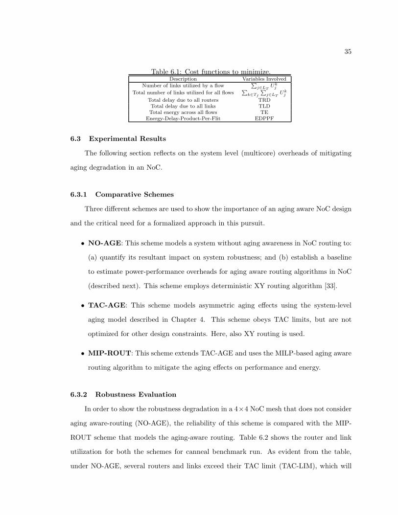
Table 6.1: Cost functions to minimize.Description Variables Involved
Number of links utilized by a flowP
j∈LTUk
j
Total number of links utilized for all flowsP
k∈Tf
P
j∈LTUk
j
Total delay due to all routers TRDTotal delay due to all links TLDTotal energy across all flows TE
Energy-Delay-Product-Per-Flit EDPPF
6.3 Experimental Results
The following section reflects on the system level (multicore) overheads of mitigating
aging degradation in an NoC.
6.3.1 Comparative Schemes
Three different schemes are used to show the importance of an aging aware NoC design
and the critical need for a formalized approach in this pursuit.
• NO-AGE: This scheme models a system without aging awareness in NoC routing to:
(a) quantify its resultant impact on system robustness; and (b) establish a baseline
to estimate power-performance overheads for aging aware routing algorithms in NoC
(described next). This scheme employs deterministic XY routing algorithm [33].
• TAC-AGE: This scheme models asymmetric aging effects using the system-level
aging model described in Chapter 4. This scheme obeys TAC limits, but are not
optimized for other design constraints. Here, also XY routing is used.
• MIP-ROUT: This scheme extends TAC-AGE and uses the MILP-based aging aware
routing algorithm to mitigate the aging effects on performance and energy.
6.3.2 Robustness Evaluation
In order to show the robustness degradation in a 4×4 NoC mesh that does not consider
aging aware-routing (NO-AGE), the reliability of this scheme is compared with the MIP-
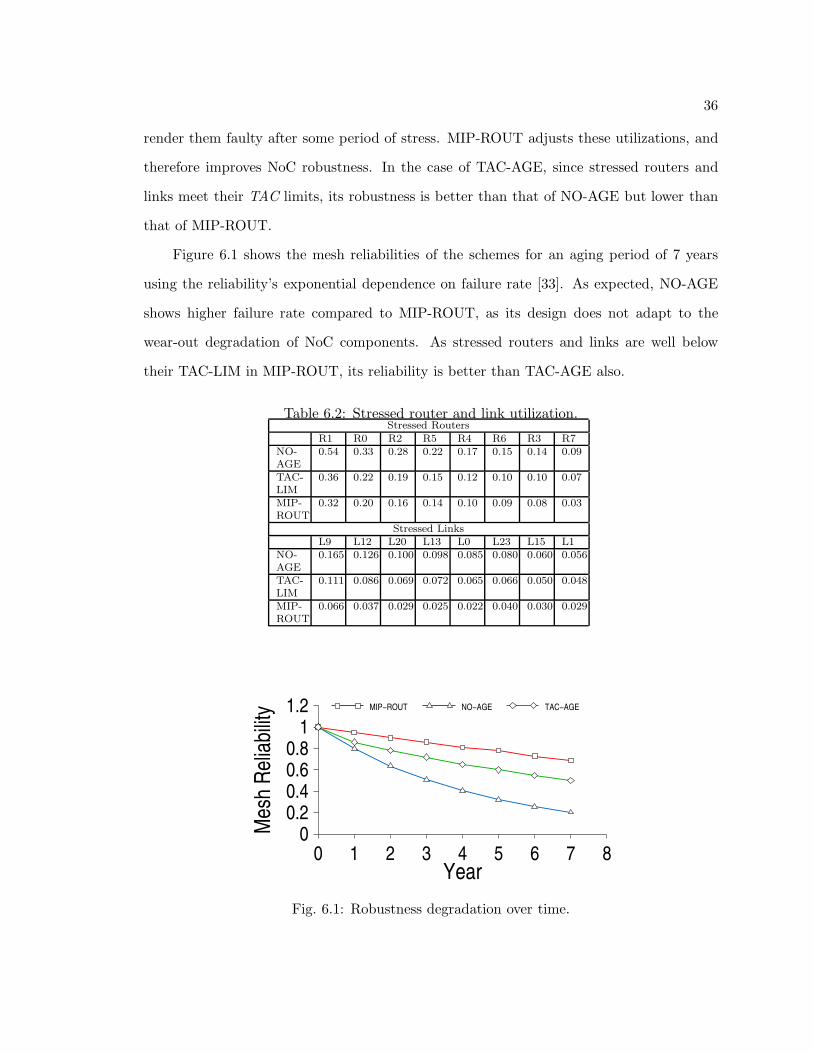
ROUT scheme that models the aging-aware routing. Table 6.2 shows the router and link
utilization for both the schemes for canneal benchmark run. As evident from the table,
under NO-AGE, several routers and links exceed their TAC limit (TAC-LIM), which will
36
render them faulty after some period of stress. MIP-ROUT adjusts these utilizations, and
therefore improves NoC robustness. In the case of TAC-AGE, since stressed routers and
links meet their TAC limits, its robustness is better than that of NO-AGE but lower than
that of MIP-ROUT.
Figure 6.1 shows the mesh reliabilities of the schemes for an aging period of 7 years
using the reliability’s exponential dependence on failure rate [33]. As expected, NO-AGE
shows higher failure rate compared to MIP-ROUT, as its design does not adapt to the
wear-out degradation of NoC components. As stressed routers and links are well below
their TAC-LIM in MIP-ROUT, its reliability is better than TAC-AGE also.
Table 6.2: Stressed router and link utilization.Stressed Routers
R1 R0 R2 R5 R4 R6 R3 R7NO-AGE
0.54 0.33 0.28 0.22 0.17 0.15 0.14 0.09
TAC-LIM
0.36 0.22 0.19 0.15 0.12 0.10 0.10 0.07
MIP-ROUT
0.32 0.20 0.16 0.14 0.10 0.09 0.08 0.03
Stressed LinksL9 L12 L20 L13 L0 L23 L15 L1
NO-AGE
0.165 0.126 0.100 0.098 0.085 0.080 0.060 0.056
TAC-LIM
0.111 0.086 0.069 0.072 0.065 0.066 0.050 0.048
MIP-ROUT
0.066 0.037 0.029 0.025 0.022 0.040 0.030 0.029
Year0 1 2 3 4 5 6 7 8
Mes
h R
elia
bilit
y
00.20.40.60.8
11.2 MIP−ROUT NO−AGE TAC−AGE
Fig. 6.1: Robustness degradation over time.
37
6.3.3 Overhead Analysis
Network Latency
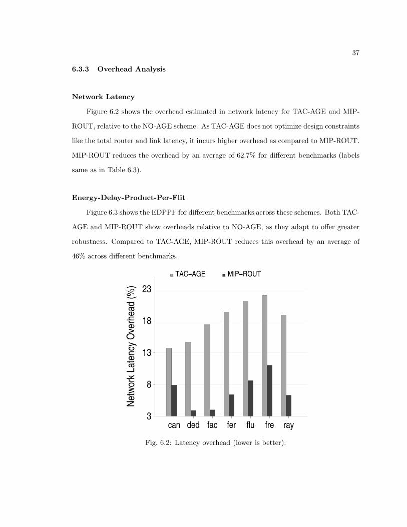
Figure 6.2 shows the overhead estimated in network latency for TAC-AGE and MIP-
ROUT, relative to the NO-AGE scheme. As TAC-AGE does not optimize design constraints
like the total router and link latency, it incurs higher overhead as compared to MIP-ROUT.
MIP-ROUT reduces the overhead by an average of 62.7% for different benchmarks (labels
same as in Table 6.3).
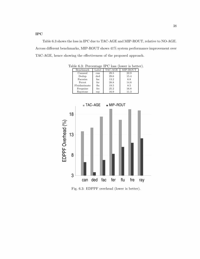
Energy-Delay-Product-Per-Flit
Figure 6.3 shows the EDPPF for different benchmarks across these schemes. Both TAC-
AGE and MIP-ROUT show overheads relative to NO-AGE, as they adapt to offer greater
robustness. Compared to TAC-AGE, MIP-ROUT reduces this overhead by an average of
46% across different benchmarks.
can ded fac fer flu fre ray
Net
wor
k La
tenc
y O
verh
ead
(%)
3
8
13
18
23
TAC−AGE MIP−ROUT
Fig. 6.2: Latency overhead (lower is better).
38
IPC
Table 6.3 shows the loss in IPC due to TAC-AGE and MIP-ROUT, relative to NO-AGE.
Across different benchmarks, MIP-ROUT shows 41% system performance improvement over
TAC-AGE, hence showing the effectiveness of the proposed approach.
Table 6.3: Percentage IPC loss (lower is better).Benchmark Label TAC-AGE MIP-ROUT
Canneal can 29.5 22.9Dedup ded 29.6 15.4Facesim fac 13.2 6.8Ferret fer 28.8 14.8
Fluidanimate flu 19.5 8.5Freqmine fre 25.2 16.8Raystone ray 16.9 11.3
can ded fac fer flu fre ray
ED
PP
F O
verh
ead
(%)
3
8
13
18
TAC−AGE MIP−ROUT
Fig. 6.3: EDPPF overhead (lower is better).
39
Chapter 7
Conclusion
This thesis has presented an analysis of the impact of aging on NoC architecture,
considering both NoC routers and links. A critical need is observed to optimize NoC
power-performance metrics while considering wear-out degradation resulting from asym-
metric utilization of NoC components. To efficiently tackle this multi-objective design
challenge, two routing algorithms are proposed: (a) Aging and congestion aware adaptive
routing algorithm, and (b) Aging-aware oblivious routing algorithm. Extensive experi-
mental analysis using real workloads demonstrates improvements in network latencies and
EDPPF for both the algorithms. At the system level also, the proposed algorithms show re-
duction in performance overhead, mitigating the effects of aging mechanisms such as NBTI
and electromigration.
40
References
[1] J. D. Owens, W. J. Dally, R. Ho, D. N. Jayasimha, S. W. Keckler, and L.-S. Peh,“Research challenges for on-chip interconnection networks,” in IEEE Micro, vol. 27,no. 5, pp. 96–108, 2007.
[2] X. Fu, T. Li, and J. A. B. Fortes, “Architecting reliable multi-core network-on-chip forsmall scale processing technology,” in IEEE Dependable Systems and Networks (DSN),pp. 111–120, 2010.
[3] C. Hernandez, F. Silla, and J. Duato, “A methodology for the characterization ofprocess variation in noc links,” in Design Automation and Test in Europe (DATE), pp.685–690, 2010.
[4] A. K. Kodi, A. Sarathy, A. Louri, and J. M. Wang, “Adaptive inter-router links for low-power, area-efficient and reliable network-on-chip (noc) architectures,” in Asia-PacificDesign Automation Conference (ASP-DAC), pp. 1–6, 2009.
[5] A. K. Mishra, N. Vijaykrishnan, and C. R. Das, “A case for heterogeneous on-chip in-terconnects for cmps,” in International Symposium on Computer Architecture (ISCA),pp. 389–400, 2011.
[6] K. Bhardwaj, K. Chakraborty, and S. Roy, “Towards graceful aging degradation in nocsthrough an adaptive routing algorithm,” in Design Automation Conference (DAC), pp.382–391, 2012.
[7] ——, “An milp based aging aware routing algorithm for nocs,” in Design Automationand Test in Europe (DATE), pp. 326–331, 2012.
[8] N. Agarwal, T. Krishna, L.-S. Peh, and N. K. Jha, “Garnet: A detailed on-chip net-work model inside a full-system simulator,” in International Symposium on PerformaceAnalysis of Systems and Software (ISPASS), pp. 33–42, 2009.
[9] PARSEC, http://parsec.cs.princeton.edu/.
[10] B. Li, L.-S. Peh, and P. Patra, “Impact of process and temperature variations onnetwork-on-chip design exploration,” in Network-On-Chip Symposium (NOCS), pp.117–126, 2008.
[11] S. Sarangi, B. Greskamp, R. Teodorescu, J. Nakano, A. Tiwari, and J. Torrellas, “Var-ius: A model of process variation and resulting timing errors for microarchitects,” inIEEE Transactions on Semiconductor Manufacturing, vol. 21, no. 1, pp. 3–13, 2008.
[12] W. Wang, S. Yang, S. Bhardwaj, R. Vattikonda, S. B. K. Vrudhula, F. Liu, and Y. Cao,“The impact of nbti on the performance of combinational and sequential circuits,” inDesign Automation Conference (DAC), pp. 364–369, 2007.
41
[13] M. Sun, M. G. Pecht, and D. Barbe, “Lifetime rc time delay of on-chip copper intercon-nect,” in IEEE Transactions on Semiconductor Manufacturing, vol. 15, pp. 253–259,2002.
[14] A. Shafiee, M. Zolghadr, M. Arjomand, and H. Sarbazi-Azad, “Application-awaredeadlock-free oblivious routing based on extended turn-model,” in IEEE InternationalConference on Computer-Aided Design (ICCAD), pp. 213–218, 2011.
[15] N. Nikitin, S. Chatterjee, J. Cortadella, M. Kishinevsky, and U. Y. Ogras, “Physical-aware link allocation and route assignment for chip multiprocessing,” in Network-On-Chip Symposium (NOCS), pp. 125–134, 2010.
[16] Z. Shi, X. Zeng, and Z. Yu, “A scalable and reconfigurable fault-tolerant distributedrouting algorithm for nocs,” in IEICE Transactions, vol. 94-D, no. 7, pp. 1386–1397,2011.
[17] D. Fick, A. DeOrio, G. K. Chen, V. Bertacco, D. Sylvester, and D. Blaauw, “A highlyresilient routing algorithm for fault-tolerant nocs,” in Design Automation and Test inEurope (DATE), pp. 21–26, 2009.
[18] F. Chaix, D. Avresky, N.-E. Zergainoh, and M. Nicolaidis, “A fault-tolerant deadlock-free adaptive routing for on chip interconnects,” in Design Automation and Test inEurope (DATE), pp. 909–912, 2011.
[19] S. Akbari, A. Shafiee, M. Fathy, and R. Berangi, “Afra: A low cost high performancereliable routing for 3d mesh nocs,” in Design Automation and Test in Europe (DATE),pp. 332–337, 2012.
[20] A. Sharifi and M. T. Kandemir, “Process variation-aware routing in noc based multi-cores,” in Design Automation Conference (DAC), pp. 924–929, 2011.
[21] T.-B. Chan, J. Sartori, P. Gupta, and R. Kumar, “On the efficacy of nbti mitigationtechniques,” in Design Automation and Test in Europe (DATE), pp. 1–6, 2011.
[22] S. Bhardwaj, W. Wang, R. Vattikonda, Y. Cao, and S. Vrudhula, “Predictive modelingof the nbti effect for reliable design,” in IEEE Custom Integrated Circuits Conference(CICC), pp. 189–192, 2006.
[23] J. Sun, A. K. Kodi, A. Louri, and J. M. Wang, “Nbti aware workload balancing in multi-core systems,” in International Symposium on Quality Electronic Design (ISQED), pp.833–838, 2009.
[24] H. Chang and S. S. Sapatnekar, “Statistical timing analysis considering spatial correla-tions using a single pert-like traversal,” in International Conference of Computer-AidedDesign (ICCAD), pp. 621–626, 2003.
[25] W. Navidi, Statistics for Engineers and Scientist, 3rd ed. New York City: McGraw-Hill, 2010.
42
[26] B. Datta and W. Burleson, “Analysis and mitigation of nbti-impact on pvt variabilityin repeated global interconnect performance,” in Great Lakes Symposium on VLSI(GLSVLSI), pp. 341–346, 2010.
[27] P. Gratz, B. Grot, and S. W. Keckler, “Regional congestion awareness for load balancein networks-on-chip,” in High Performance Computer Architecture (HPCA), pp. 203–214, 2008.
[28] Open Source NoC Router RTL, https://nocs.stanford.edu/cgi-bin/trac.cgi/wiki/Resources/Router.
[29] M. M. K. Martin, D. J. Sorin, B. M. Beckmann, M. R. Marty, M. Xu, A. R. Alameldeen,K. E. Moore, M. D. Hill, and D. A. Wood, “Multifacets general execution-drivenmultiprocessor simulator (gems) toolset,” in SIGARCH Computer Architecture News,vol. 33, pp. 92–99, 2005.
[30] A. B. Kahng, B. Li, L.-S. Peh, and K. Samadi, “Orion 2.0: A fast and accurate nocpower and area model for early-stage design space exploration,” in Design Automationand Test in Europe (DATE), pp. 423–428, 2009.
[31] J. Hu and R. Marculescu, “Energy- and performance-aware mapping for regular nocarchitectures,” in IEEE Transactions on Computer-Aided Design of Integrated Circuitsand Systems (TCAD), vol. 24, no. 4, pp. 551–562, 2005.
[32] IBM, ILOG CPLEX, http://www.ilog.com/products/cplex/.
[33] W. J. Dally and B. Towles, Principles and Practices of Interconnection Networks. SanFrancisco: Morgan Kaufmann, 2004.


