Embed Size (px)
Citation preview
Agilent 7000 Triple Quadrupole GC/MS System
Troubleshooting and Maintenance Manual
Agilent Technologies
Notices© Agilent Technologies, Inc. 2013
No part of this manual may be reproduced in any form or by any means (including elec-tronic storage and retrieval or translation into a foreign language) without prior agree-ment and written consent from Agilent Technologies, Inc. as governed by United States and international copyright laws.
Manual Part NumberG7000-90043
EditionFirst edition, August 2013
Printed in USA
Agilent Technologies, Inc.5301 Stevens Creek BoulevardSanta Clara, CA 95051
Warranty
The material contained in this docu-ment is provided “as is,” and is sub-ject to being changed, without notice, in future editions. Further, to the max-imum extent permitted by applicable law, Agilent disclaims all warranties, either express or implied, with regard to this manual and any information contained herein, including but not limited to the implied warranties of merchantability and fitness for a par-ticular purpose. Agilent shall not be liable for errors or for incidental or consequential damages in connec-tion with the furnishing, use, or per-formance of this document or of any information contained herein. Should Agilent and the user have a separate written agreement with warranty terms covering the material in this document that conflict with these terms, the warranty terms in the sep-arate agreement shall control.
Safety Notices
CAUTION
A CAUTION notice denotes a hazard. It calls attention to an operating procedure, practice, or the like that, if not correctly performed or adhered to, could result in damage to the product or loss of important data. Do not proceed beyond a CAUTION notice until the indicated conditions are fully understood and met.
WARNING
A WARNING notice denotes a hazard. It calls attention to an operating procedure, practice, or the like that, if not correctly performed or adhered to, could result in personal injury or death. Do not proceed beyond a WARNING notice until the indicated conditions are fully understood and met.
2 Troubleshooting and Maintenance Manual
Contents
1 Introduction
Troubleshooting and Maintenance M
Abbreviations Used 8
The 7000 Triple Quad GC/MS 10
7000 Triple Quadrupole CI System 11
7000 Triple Quad GC/MS Hardware Description 12
Important Safety Warnings 13
Hydrogen Safety 16
Safety and Regulatory Certifications 21
Intended Use 24
Cleaning/Recycling the Product 24
Liquid Spills 24
Moving or Storing the MS 24
2 General Troubleshooting
Troubleshooting Tips and Tricks 26
General Symptoms 27
Chromatographic Symptoms 29
Mass Spectra General Symptoms 34
Pressure Symptoms 38
Temperature Symptoms 40
Common Types of Errors 42
Air Leaks 47
Contamination 48
anual 3
3 CI Troubleshooting
4
Common CI-Specific Problems 52
Troubleshooting Tips and Tricks 53
Air Leaks 54
Pressure-Related Symptoms 58
Signal-Related Symptoms 62
Tuning-Related Symptoms 70
4 General Maintenance
Before Starting 76
Maintaining the Mainframe 80
To refill/purge the EI calibration vial 89
Maintaining the Vacuum System 90
To remove/install the ion vacuum gauges 91
Maintaining the Foreline Pump 94
To check the foreline pump fluid level 95To add foreline pump fluid 96To replace the foreline pump fluid 97
Maintaining the Analyzers and Collision Cell 105
Maintaining the Electronics 110
5 CI Maintenance
To Minimize Foreline Pump Damage from Ammonia 116
To Replace the Methane/Isobutane Gas Purifier 117
To Clean the Reagent Gas Supply Lines 118
To Refill the CI Calibrant Vial 119
Troubleshooting and Maintenance Manual
6 Vacuum System
Troubleshooting and Maintenance M
Overview 122
Vacuum System Components 123
Common Vacuum System Problems 124
Foreline Pump 125
Turbo Pump 127
Analyzer Chambers 127
Side Plates 128
Vacuum Seals 129
Foreline Gauge 131
Turbo Pump and Fan 132
Calibration Valve and Vent Valve 133
7 Analyzers and Collision Cell
Overview 136
EI Ion Source 138
Filaments 139
Other Source Elements 141
CI Ion Source 143
Quadrupole Mass Filters 145
Post- and Pre-Filters 148
Collision Cell 149
Detector 150
Analyzer Heaters and Radiators 153
anual 5
8 Electronics
6
Power Switch 156
Ion Source Board 157
Quadrupole Boards 158
Collision Cell Board 159
Detector Board 160
Electronics Module 161
Bus board 166
PLX card 166
LAN/MS Control Card (Smartcard 4) 166
Power Supplies 167
Back Panel Connectors 168
Interfacing to External Devices 170
9 Replacement Parts
To Order Parts 174
Electronics 175
Vacuum System 176
Analyzer 178
EI GC/MS Interface 183
Consumables and Maintenance Supplies 184
Additional CI Parts 188
Troubleshooting and Maintenance Manual
Agilent 7000 Series Triple Quadrupole GC/MS Troubleshooting and Maintenance Manual
1Introduction
Abbreviations Used 8
The 7000 Triple Quad GC/MS 10
7000 Triple Quad GC/MS Hardware Description 12
Important Safety Warnings 13
Hydrogen Safety 16
Safety and Regulatory Certifications 21
Intended Use 24
Cleaning/Recycling the Product 24
Liquid Spills 24
Moving or Storing the MS 24
This manual describes the troubleshooting and maintenance of the Agilent Technologies 7000 Triple Quadrupole GC/MS system. It is often referred to in this document as the 7000 Triple Quad GC/MS. This manual assumes familiarity with the procedures and information detailed in the Agilent 7000 Triple Quad GC/MS Operation Manual and with the Agilent MassHunter Workstation software.
The 7000 Triple Quad GC/MS system consists of a 7890 Gas Chromatograph (GC) and a 7000 Triple Quad GC/MS.
This section provides general information about the 7000 Triple Quad GC/MS, including a hardware description, general safety warnings, and hydrogen safety information.
7Agilent Technologies
1 Introduction
Abbreviations Used
8
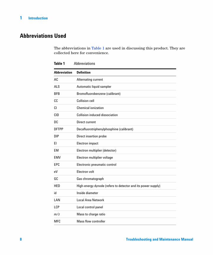
The abbreviations in Table 1 are used in discussing this product. They are collected here for convenience.
Table 1 Abbreviations
Abbreviation Definition
AC Alternating current
ALS Automatic liquid sampler
BFB Bromofluorobenzene (calibrant)
CC Collision cell
CI Chemical ionization
CID Collision induced dissociation
DC Direct current
DFTPP Decafluorotriphenylphosphine (calibrant)
DIP Direct insertion probe
EI Electron impact
EM Electron multiplier (detector)
EMV Electron multiplier voltage
EPC Electronic pneumatic control
eV Electron volt
GC Gas chromatograph
HED High-energy dynode (refers to detector and its power supply)
id Inside diameter
LAN Local Area Network
LCP Local control panel
m/z Mass to charge ratio
MFC Mass flow controller
Troubleshooting and Maintenance Manual
Introduction 1
Troubleshooting and
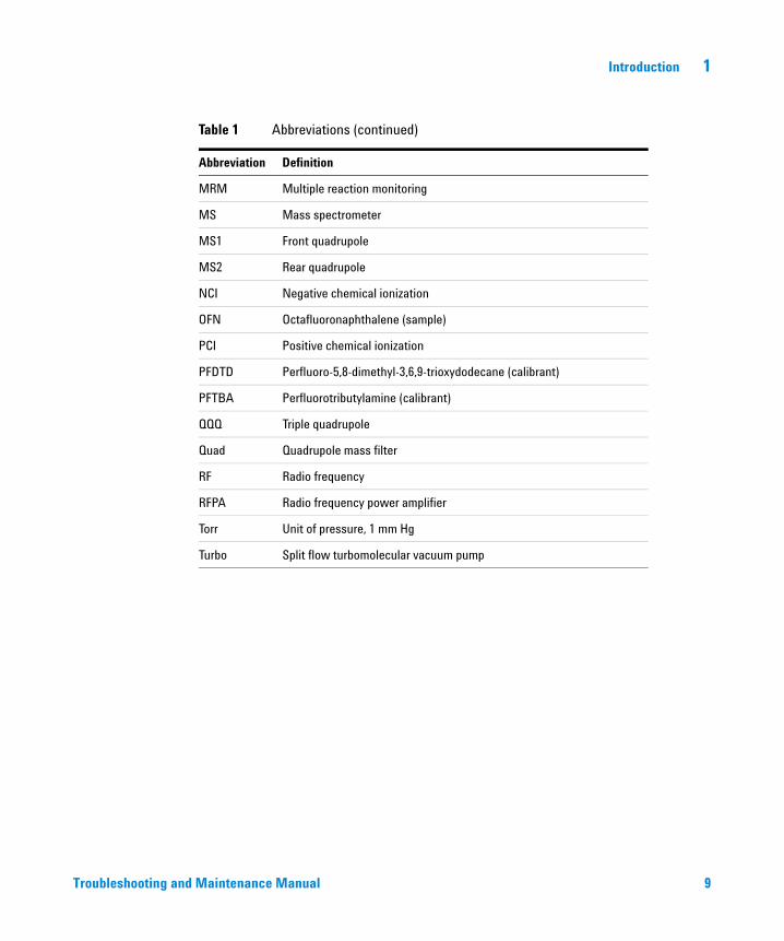
MRM Multiple reaction monitoring
MS Mass spectrometer
MS1 Front quadrupole
MS2 Rear quadrupole
NCI Negative chemical ionization
OFN Octafluoronaphthalene (sample)
PCI Positive chemical ionization
PFDTD Perfluoro-5,8-dimethyl-3,6,9-trioxydodecane (calibrant)
PFTBA Perfluorotributylamine (calibrant)
QQQ Triple quadrupole
Quad Quadrupole mass filter
RF Radio frequency
RFPA Radio frequency power amplifier
Torr Unit of pressure, 1 mm Hg
Turbo Split flow turbomolecular vacuum pump
Table 1 Abbreviations (continued)
Abbreviation Definition
Maintenance Manual 9
1 Introduction
The 7000 Triple Quad GC/MS
10
The 7000 Triple Quad GC/MS is a standalone capillary GC detector for use with the Agilent 7890 Series Gas Chromatograph. The Triple Quad MS features:
• One split flow turbomolecular vacuum pump
• Rotary vane foreline pump
• Independently MS heated high sensitivity electron ionization source with self clean option available
• Chemical and electron-ionization modes available (PCI/NCI/EI)
• Two independently MS heated hyperbolic quadrupole mass filters
• Single hexapole collision cell
• Choice of two high-energy dynode (HED) electron multiplier detectors with high sensitivity electronics
• Independently GC heated GC/MS interface
• Independently GC controlled collision cell gas flows
• Local control panel (LCP) for locally monitoring the MS
Physical description
The 7000 Triple Quad GC/MS is a rectangular box, approximately 47 cm high, 35 cm wide, and 86 cm deep. The weight is 59 kg for the turbo pump mainframe and 64 kg for the mainframe with CI upgrade. The attached foreline (roughing) pump weighs an additional 11 kg.
The basic components of the instrument are: the frame/cover assemblies, the vacuum system, the GC/MS interface, the ion source, the electronics, the collision cell, the detector, and the front and rear analyzers.
Local control panel
The local control panel allows local monitoring of the MS instrument status.
Vacuum gauge
The 7000 Triple Quad GC/MS is equipped with two ion vacuum gauges. The MassHunter Workstation can be used to read the pressure (high vacuum) in the vacuum manifold and at the turbomolecular vacuum pump discharge.
Troubleshooting and Maintenance Manual
Introduction 1
7000 Triple Quadrupole CI System
Troubleshooting and
In this manual, the term “CI MS” refers to the 7000 Triple Quad GC/MS CI source system. It also applies, unless otherwise specified, to the flow modules for these instruments.
The 7000 Triple Quad GC/MS CI source system upgrade kit adds to the 7000 Triple Quad MS:
• EI/CI GC/MS interface
• CI ion source and EI/CI interface tip seal
• Reagent gas flow control module
• Bipolar HED power supply for PCI and NCI operation
A methane/isobutane gas purifier is provided and is required. It removes oxygen, water, hydrocarbons, and sulfur compounds.
The MS CI system has been optimized to achieve the relatively high source pressure required for CI while still maintaining high vacuum in the collision cell, quadrupoles, and detector. Special seals along the flow path of the reagent gas and very small openings in the ion source keep the source gases in the ionization volume long enough for the appropriate reactions to occur.
The CI interface has special plumbing for reagent gas. A spring-loaded insulating seal fits onto the tip of the interface.
Switching back and forth between CI and EI sources takes less than an hour, although a 1- to 2-hour wait is required to purge the reagent gas lines and bake out water and other contaminants. Switching from PCI to NCI requires about 2 hours for the ion source to cool.
Maintenance Manual 11
1 Introduction
7000 Triple Quad GC/MS Hardware Description
12
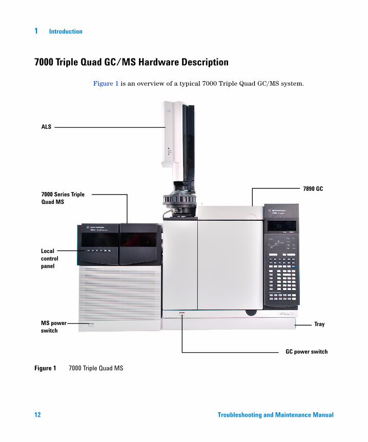
Figure 1 is an overview of a typical 7000 Triple Quad GC/MS system.
Figure 1 7000 Triple Quad MS
ALS
7000 Series Triple Quad MS
Local control panel
MS power switch
7890 GC
Tray
GC power switch
Troubleshooting and Mainten
ance Manual
Introduction 1
Important Safety Warnings
Troubleshooting and
There are several important safety notices to always keep in mind when using the MS.
Many internal parts of the MS carry dangerous voltages
If the MS is connected to a power source, even if the power switch is off, potentially dangerous voltages exist on:
• The wiring between the MS power cord and the AC power supply
• The AC power supply itself
• The wiring from the AC power supply to the power switch
With the power switch on, potentially dangerous voltages also exist on:
• All electronics boards in the instrument
• The internal wires and cables connected to these boards
• The wires for any heater (oven, detector, inlet, or valve box)
All these parts are shielded by covers. With the covers in place, it should be difficult
WARNINGto accidentally make contact with dangerous voltages. Unless specifically instructed to, never remove a cover unless the detector, inlet, and oven are turned off.If the power cord insulation is frayed or worn, the cord must be replaced. Contact
Electrostatic discharge is a threat to MS electronics
WARNINGyour Agilent service representative.
The printed circuit boards in the MS can be damaged by electrostatic discharge. Do not touch any of the boards unless it is absolutely necessary. If you must handle them, wear a grounded wrist strap and take other antistatic precautions.
Maintenance Manual 13
1 Introduction
Many parts are dangerously hot
14
Many parts of the GC/MS operate at temperatures high enough to cause serious burns. These parts include, but are not limited to the:
• Inlet
• Oven and its contents
• Valve box
• Detectors
• Column nuts attaching the column to an inlet or detector
• Foreline pump
• GC/MS transfer line
• Quadrupoles
• Ion source
Always cool these areas of the system to room temperature before working on them. They will cool faster if you first set the temperature of the heated zone to room temperature. Turn the zone off after it has reached the setpoint. If you must perform maintenance on hot parts, use a wrench and wear gloves. Whenever possible, cool the part of the instrument that you will be maintaining before you begin working on it.
Be careful when working behind the instrument. During cool-down cycles, the GC
WARNINGemits hot exhaust that can cause burns.The insulation around the inlets, detectors, valve box, and the insulation cups is
The oil pan under the standard foreline pump can be a fire hazard
WARNINGmade of refractory ceramic fibers. To avoid inhaling fiber particles, we recommend the following safety procedures: ventilate your work area; wear long sleeves, gloves, safety glasses, and a disposable dust/mist respirator; dispose of insulation in a sealed plastic bag in accordance with local regulations; wash your hands with mild soap and cold water after handling the insulation.
Oily rags, paper towels, and similar absorbents in the oil pan could ignite and damage the pump and other parts of the MS.
Troubleshooting and Maintenance Manual
Introduction 1
WARNING Combustible materials (or flammable/nonflammable wicking material) placed under, over, or around the foreline (roughing) pump constitutes a fire hazard. Keep the pan clean, but do not leave absorbent material such as paper towels in it.
Troubleshooting and Maintenance Manual 15
1 Introduction
Hydrogen Safety
16
The use of hydrogen as a GC carrier gas is potentially dangerous.
WARNINGWhen using hydrogen (H ) as the carrier gas or fuel gas, be aware that hydrogen
WARNING 2gas can flow into the GC oven and create an explosion hazard. Therefore, be sure that the hydrogen supply is turned off until all connections are made and ensure that the inlet and detector column fittings are either connected to a column or capped at all times when hydrogen gas is supplied to the instrument.Hydrogen is flammable. Leaks, when confined in an enclosed space, may create a fire or explosion hazard. In any application using hydrogen, leak test all connections, lines, and valves before operating the instrument. Always turn off the hydrogen supply at its source before working on the instrument.
Hydrogen is a commonly used GC carrier gas. Hydrogen is potentially explosive and has other dangerous characteristics.
• Hydrogen is combustible over a wide range of concentrations. At atmospheric pressure, hydrogen is combustible at concentrations from 4% to 74.2% by volume.
• Hydrogen has the highest burning velocity of any gas.
• Hydrogen has a very low ignition energy.
• Hydrogen that is allowed to expand rapidly from high pressure can self-ignite.
• Hydrogen burns with a nonluminous flame, which can be invisible under bright light.
Dangers unique to GC/MS operation
Hydrogen presents a number of dangers. Some are general, others are unique to GC or GC/MS operation. Dangers include, but are not limited to:
• Combustion of leaking hydrogen
• Combustion due to rapid expansion of hydrogen from a high-pressure cylinder
Troubleshooting and Maintenance Manual
Introduction 1
Troubleshooting and
• Accumulation of hydrogen in the GC oven and subsequent combustion (See your GC documentation and the label on the top edge of the GC oven door.)
• Accumulation of hydrogen in the MS and subsequent combustion
Hydrogen accumulation in an MS
The MS cannot detect leaks in inlet and/or detector gas streams. For this reason, it
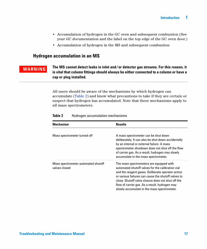
WARNINGis vital that column fittings should always be either connected to a column or have a cap or plug installed.All users should be aware of the mechanisms by which hydrogen can accumulate (Table 2) and know what precautions to take if they are certain or suspect that hydrogen has accumulated. Note that these mechanisms apply to all mass spectrometers.
Table 2 Hydrogen accumulation mechanisms
Mechanism Results
Mass spectrometer turned off A mass spectrometer can be shut down deliberately. It can also be shut down accidentally by an internal or external failure. A mass spectrometer shutdown does not shut off the flow of carrier gas. As a result, hydrogen may slowly accumulate in the mass spectrometer.
Mass spectrometer automated shutoffvalves closed
The mass spectrometers are equipped with automated shutoff valves for the calibration vial and the reagent gases. Deliberate operator action or various failures can cause the shutoff valves to close. Shutoff valve closure does not shut off the flow of carrier gas. As a result, hydrogen may slowly accumulate in the mass spectrometer.
Maintenance Manual 17
18
1 Introduction
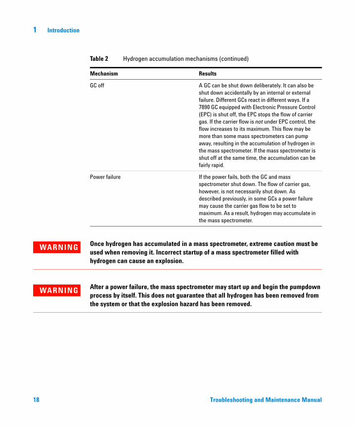
GC off A GC can be shut down deliberately. It can also be shut down accidentally by an internal or external failure. Different GCs react in different ways. If a 7890 GC equipped with Electronic Pressure Control (EPC) is shut off, the EPC stops the flow of carrier gas. If the carrier flow is not under EPC control, the flow increases to its maximum. This flow may be more than some mass spectrometers can pump away, resulting in the accumulation of hydrogen in the mass spectrometer. If the mass spectrometer is shut off at the same time, the accumulation can be fairly rapid.
Power failure If the power fails, both the GC and mass spectrometer shut down. The flow of carrier gas, however, is not necessarily shut down. As described previously, in some GCs a power failure may cause the carrier gas flow to be set to maximum. As a result, hydrogen may accumulate in the mass spectrometer.
Table 2 Hydrogen accumulation mechanisms (continued)
Mechanism Results
Once hydrogen has accumulated in a mass spectrometer, extreme caution must be
WARNINGused when removing it. Incorrect startup of a mass spectrometer filled with hydrogen can cause an explosion.After a power failure, the mass spectrometer may start up and begin the pumpdown
WARNINGprocess by itself. This does not guarantee that all hydrogen has been removed from the system or that the explosion hazard has been removed.Troubleshooting and Maintenance Manual
Introduction 1
Precautions
Troubleshooting and
Take the following precautions when operating a GC/MS system with hydrogen carrier gas.
Equipment precautions
You MUST make sure the top thumbscrew on the front analyzer side plate and the
WARNINGtop thumbscrew on the rear analyzer side plate are both fastened finger-tight. Do not overtighten the thumbscrews; this can cause air leaks.You MUST leave the collision cell chamber top plate shipping brackets fastened. Do not remove the shipping brackets from the top plate for normal operation; they secure the top plate in the event of an explosion.
You must remove the plastic cover over the glass window on the front of the analyzer. In the unlikely event of an explosion, this cover may dislodge.
Failure to secure your MS as described above greatly increases the chance of
WARNINGpersonal injury in the event of an explosion.General laboratory precautions
• Avoid leaks in the carrier gas lines. Use leak-checking equipment to periodically check for hydrogen leaks.
• Eliminate from your laboratory as many ignition sources as possible (for example, open flames, devices that can spark and sources of static electricity).
• Do not allow hydrogen from a high pressure cylinder to vent directly to atmosphere (danger of self-ignition).
• Use a hydrogen generator instead of bottled hydrogen.
Operating precautions
• Turn off the hydrogen at its source every time you shut down the GC or MS.
• Do not use hydrogen as a collision cell gas.
Maintenance Manual 19
20
1 Introduction
• Turn off the hydrogen at its source every time you vent the MS (do not heat the capillary column without carrier gas flow).
• Turn off the hydrogen at its source every time shutoff valves in the MS are closed (do not heat the capillary column without carrier gas flow).
• Turn off the hydrogen at its source if a power failure occurs.
• If a power failure occurs while the GC/MS system is unattended, even if the system has restarted by itself:
1 Immediately turn off the hydrogen at its source.
2 Turn off the GC.
3 Turn off the MS and allow it to cool for 1 hour.
4 Eliminate all potential sources of ignition in the room.
5 Open the vacuum manifold of the MS to atmosphere.
6 Wait at least 10 minutes to allow any hydrogen to dissipate.
7 Start up the GC and MS as normal.
When using hydrogen gascheck the system for leaks to prevent possible fire and explosion hazards based on local Environmental Health and Safety (EHS) requirements. Always check for leaks after changing a tank or servicing the gas lines. Always make sure the vent line is vented into a fume hood.
Troubleshooting and Maintenance Manual
Introduction 1
Safety and Regulatory Certifications
Troubleshooting and
The 7000 Triple Quad GC/MS conforms to the following safety standards:
• Canadian Standards Association (CSA): CAN/CSA-C222 No. 61010-1-04
• CSA/Nationally Recognized Test Laboratory (NRTL): UL 61010–1
• International Electrotechnical Commission (IEC): 61010–1
• EuroNorm (EN): 61010–1
The 7000 Triple Quad MS conforms to the following regulations on Electromagnetic Compatibility (EMC) and Radio Frequency Interference (RFI):
• CISPR 11/EN 55011: Group 1, Class A
• IEC/EN 61326
• AUS/NZ
This ISM device complies with Canadian ICES-001. Cet appareil ISM est conforme a la norme NMB—001 du Canada.
The 7000 Triple Quad GC/MS is designed and manufactured under a quality system registered to ISO 9001.
Information
The Agilent Technologies 7000 Triple Quad GC/MS meets the following IEC (International Electrotechnical Commission) classifications: Equipment Class I, Laboratory Equipment, Installation Category II, and Pollution Degree 2.
This unit has been designed and tested in accordance with recognized safety standards and is designed for use indoors. If the instrument is used in a manner not specified by the manufacturer, the protection provided by the instrument may be impaired. Whenever the safety protection of the MS has been compromised, disconnect the unit from all power sources and secure the unit against unintended operation.
Refer servicing to qualified service personnel. Substituting parts or performing any unauthorized modification to the instrument may result in a safety hazard.
Maintenance Manual 21
1 Introduction
Symbols
22
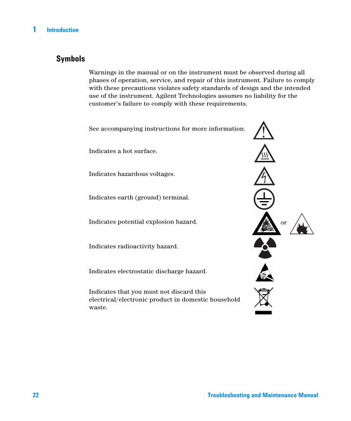
Warnings in the manual or on the instrument must be observed during all phases of operation, service, and repair of this instrument. Failure to comply with these precautions violates safety standards of design and the intended use of the instrument. Agilent Technologies assumes no liability for the customer’s failure to comply with these requirements.
See accompanying instructions for more information.
Indicates a hot surface.
Indicates hazardous voltages.
Indicates earth (ground) terminal.
Indicates potential explosion hazard.
Indicates radioactivity hazard.
Indicates electrostatic discharge hazard.
Indicates that you must not discard this electrical/electronic product in domestic household waste.
or
Troubleshooting and Maintenance Manual
Introduction 1
Electromagnetic compatibility
Troubleshooting and
This device complies with the requirements of CISPR 11. Operation is subject to the following two conditions:
• This device may not cause harmful interference.
• This device must accept any interference received, including interference that may cause undesired operation.
If this equipment does cause harmful interference to radio or television reception, which can be determined by turning the equipment off and on, the user is encouraged to try one or more of the following measures:
1 Relocate the radio or antenna.
2 Move the device away from the radio or television.
3 Plug the device into a different electrical outlet, so that the device and the radio or television are on separate electrical circuits.
4 Make sure that all peripheral devices are also certified.
5 Make sure that appropriate cables are used to connect the device to peripheral equipment.
6 Consult your equipment dealer, Agilent Technologies, or an experienced technician for assistance.
Changes or modifications not expressly approved by Agilent Technologies could void the user’s authority to operate the equipment.
Sound emission declaration
Sound pressure
Sound pressure Lp < 70 dB according to EN 27779:1991 and EN ISO 3744:1995.
Schalldruckpegel
Schalldruckpegel LP < 70 dB nach EN 27779:1991 und EN ISO 3744:1995.
Maintenance Manual 23
1 Introduction
Intended Use
24
Agilent products must only be used in the manner described in the Agilent product user guides. Any other use may result in damage to the product or personal injury. Agilent is not responsible for any damages caused, in whole or in part, by improper use of the products, unauthorized alterations, adjustments or modifications to the products, failure to comply with procedures in Agilent product user guides, or use of the products in violation of applicable laws, rules or regulations.
Cleaning/Recycling the Product
To clean the unit, disconnect the power and wipe down with a damp, lint-free cloth. For recycling, contact your local Agilent sales office.
Liquid Spills
Do not spill liquids on the MS.
Moving or Storing the MS
The best way to keep your MS functioning properly is to keep it pumped down and hot, with carrier gas flow. If you plan to move or store your MS, a few additional precautions are required. The MS must remain upright at all times; this requires special caution when moving. The MS should not be left vented to atmosphere for long periods. For more information, see To Move or Store the MS in the Operation Manual.
Troubleshooting and Maintenance Manual
Agilent 7000 Series Triple Quadrupole GC/MS Troubleshooting and Maintenance Manual
2General Troubleshooting
Troubleshooting Tips and Tricks 26
General Symptoms 27
Chromatographic Symptoms 29
Mass Spectra General Symptoms 34
Pressure Symptoms 38
Temperature Symptoms 40
Common Types of Errors 42
Air Leaks 47
Contamination 48
This is a quick reference to symptoms and possible causes of the most common problems experienced by users. See Chapter 3, “CI Troubleshooting” on page 51 for help with CI-specific problems. For each symptom, one or more possible causes are listed. In general, the causes listed first are the most likely causes or the easiest to check and correct.
This chapter does not include corrective actions for the possible causes listed. Some of the corrective actions required may be dangerous if performed incorrectly. Do not attempt any corrective actions unless you are sure you know the correct procedure and the dangers involved. See the other chapters in this manual for more information.
If the material in this chapter and in the online help proves insufficient to help you diagnose a problem, contact your Agilent Technologies service representative.
25Agilent Technologies
2 General Troubleshooting
Troubleshooting Tips and Tricks
Rule 1: “Look for what has been changed.”
26
Many problems are introduced accidentally by human actions. Every time any system is disturbed, there is a chance of introducing a new problem.
• If the MS was just pumped down after maintenance, suspect air leaks or incorrect assembly.
• If carrier gas or helium gas purifier was just changed, suspect leaks or contaminated or incorrect gas.
• If the GC column was just replaced, suspect air leaks or a contaminated or bleeding column.
Rule 2: “If complex isn’t working, go back to simple.”
A complex task is not only more difficult to perform but also more difficult to troubleshoot. If you’re having trouble detecting your sample, verify that autotune is successful.
Rule 3: “Divide and conquer.”
This technique is known as “half-split” troubleshooting. If you can isolate the problem to only part of the system, it is much easier to locate.
To determine whether an air leak is in the GC or the MS, you can vent the MS, remove the column, and install the blank interface ferrule. If the leak goes away, it was in the GC.
Troubleshooting and Maintenance Manual
General Troubleshooting 2
General Symptoms
Troubleshooting and
This section describes symptoms you might observe when first turning on the GC/MS system. All of these symptoms would prevent operation of the system.
GC does not turn on
Nothing happens when the GC is switched on. The GC fans do not turn on and the keypad display does not light.
• Disconnected GC power cord
• No voltage or incorrect voltage at the electrical outlet
• Failed fuse in the GC
• GC power supply is not working correctly
MS does not turn on
Nothing happens when the MS is switched on. The foreline pump does not start. The cooling fan for the high-vacuum pump does not turn on. The local control panel (LCP) does not turn on.
• Disconnected MS power cord
• No voltage or incorrect voltage at the electrical outlet
• Failed primary fuses
• MS electronics are not working correctly
Foreline pump is not operating
The MS is receiving power (the fan is operating and the local control panel is lit) but the foreline pump is not operating.
• A large air leak (usually the analyzer door open) has caused pumpdown failure. See “Pumpdown failure shutdown” on page 124. You must power cycle the MS to recover from this state.
• Disconnected foreline pump power cord
• Malfunctioning foreline pump
• Check power switch on foreline pump
Maintenance Manual 27
2 General Troubleshooting
MS turns on but then the foreline pump shuts off
28
The MS will shut down both the foreline pump and the high vacuum pump if the system fails to pump down correctly. This is usually because of a large air leak: either the side plate has not sealed correctly or the vent valve is still open. This feature helps prevent the foreline pump from sucking air through the system, which can damage the analyzer and pump.
See “Pumpdown failure shutdown” on page 124. You must power cycle the MS to recover from this state.
Local control panel says “No server found”
• Disconnected LAN cable between MS and the hub, or the hub and the PC
• PC is turned off
• Holding the No/Cancel key down for 5 seconds will bypass error and allow the user to look at the LCP.
Troubleshooting and Maintenance Manual
General Troubleshooting 2
Chromatographic Symptoms
Troubleshooting and
These are symptoms you may observe in the chromatograms generated by data acquisition. In general, these symptoms do not prevent you from operating your GC/MS system. They indicate, however, that the data you are acquiring may not be the best data obtainable. These symptoms can be caused by instrument malfunctions but are more likely caused by incorrect chromatographic technique.
Two of the symptoms, Low sensitivity and Poor repeatability also apply to mass spectral data.
No peaks
If an analysis shows no chromatographic peaks, only a flat baseline or minor noise, run the automated tune program. If the MS passes tune, the problem is most likely related to the GC. If the MS does not pass tune, the problem is most likely in the MS.
Passes tune
• Incorrect sample concentration
• No analytes present
• Syringe missing from the ALS or not installed correctly
• Injection accidentally made in split mode instead of splitless mode
• Empty or almost empty sample vial
• Dirty GC inlet
• Leaking GC inlet*
• Loose column nut at the GC inlet*
* This could cause a fault condition in the GC that would prevent the GC from operating.
Does not pass tune
• Calibration vial is empty
• Excessive foreline or analyzer chamber pressure
• Very dirty ion source
Maintenance Manual 29
30
2 General Troubleshooting
• Calibration valve is not working correctly
• Bad signal cable connection
• Filament has failed or is not connected correctly
• Bad ion source wiring connection
• Bad detector wiring connection
• Failed electron multiplier horn
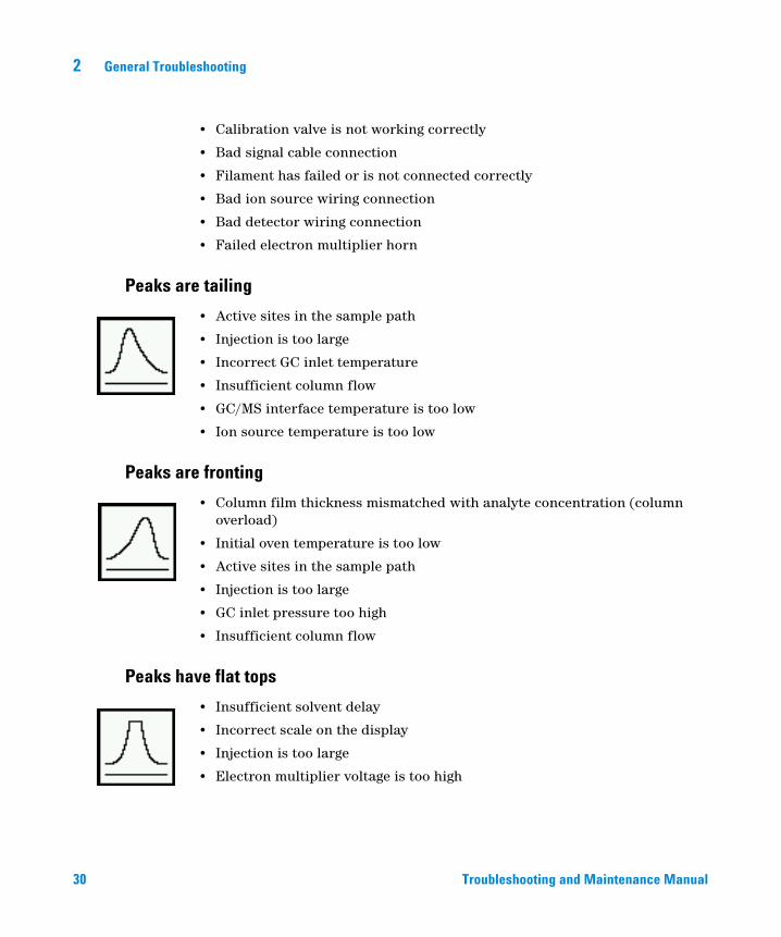
Peaks are tailing
• Active sites in the sample path
• Injection is too large
• Incorrect GC inlet temperature
• Insufficient column flow
• GC/MS interface temperature is too low
• Ion source temperature is too low
Peaks are fronting
• Column film thickness mismatched with analyte concentration (column overload)
• Initial oven temperature is too low
• Active sites in the sample path
• Injection is too large
• GC inlet pressure too high
• Insufficient column flow
Peaks have flat tops
• Insufficient solvent delay
• Incorrect scale on the display
• Injection is too large
• Electron multiplier voltage is too high
Troubleshooting and Maintenance Manual
General Troubleshooting 2
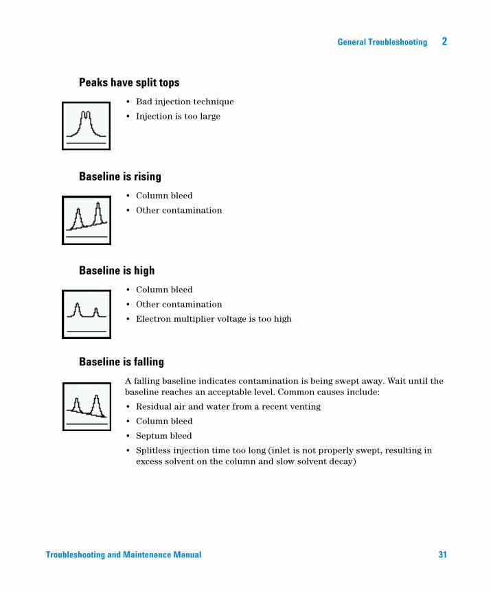
Peaks have split tops
Troubleshooting and
• Bad injection technique
• Injection is too large
Baseline is rising
• Column bleed
• Other contamination
Baseline is high
• Column bleed
• Other contamination
• Electron multiplier voltage is too high
Baseline is falling
A falling baseline indicates contamination is being swept away. Wait until the baseline reaches an acceptable level. Common causes include:
• Residual air and water from a recent venting
• Column bleed
• Septum bleed
• Splitless injection time too long (inlet is not properly swept, resulting in excess solvent on the column and slow solvent decay)
Maintenance Manual 31
2 General Troubleshooting
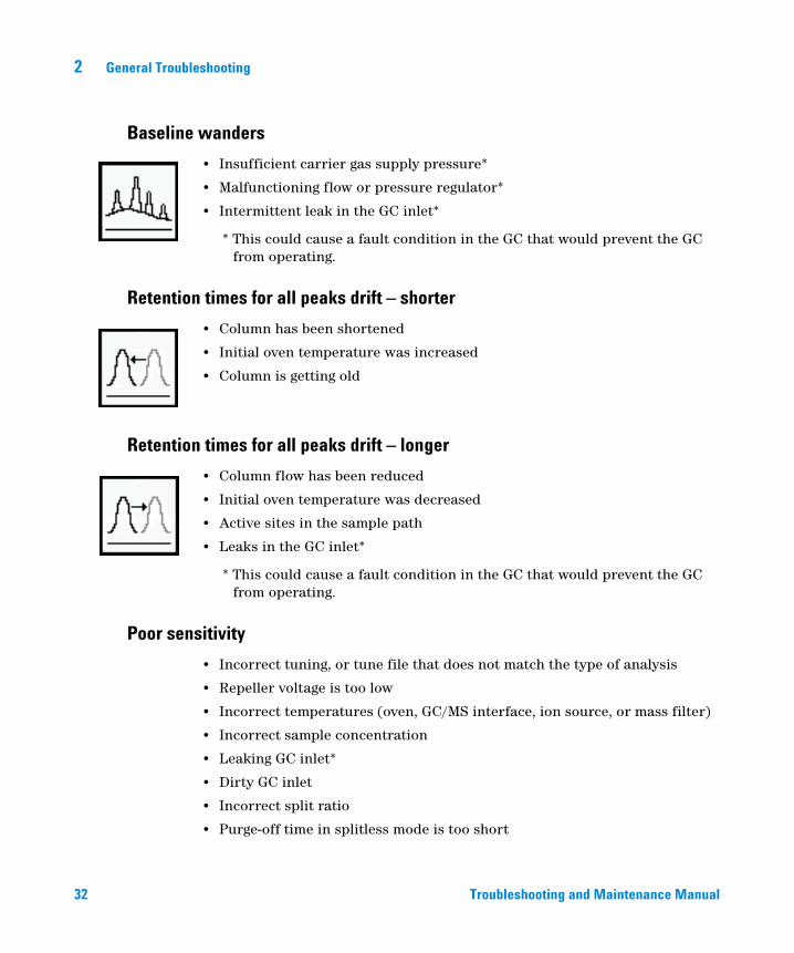
Baseline wanders
32
• Insufficient carrier gas supply pressure*
• Malfunctioning flow or pressure regulator*
• Intermittent leak in the GC inlet*
* This could cause a fault condition in the GC that would prevent the GC from operating.
Retention times for all peaks drift – shorter
• Column has been shortened
• Initial oven temperature was increased
• Column is getting old
Retention times for all peaks drift – longer
• Column flow has been reduced
• Initial oven temperature was decreased
• Active sites in the sample path
• Leaks in the GC inlet*
* This could cause a fault condition in the GC that would prevent the GC from operating.
Poor sensitivity
• Incorrect tuning, or tune file that does not match the type of analysis
• Repeller voltage is too low
• Incorrect temperatures (oven, GC/MS interface, ion source, or mass filter)
• Incorrect sample concentration
• Leaking GC inlet*
• Dirty GC inlet
• Incorrect split ratio
• Purge-off time in splitless mode is too short
Troubleshooting and Maintenance Manual
General Troubleshooting 2
Troubleshooting and
• Excessive pressure in the front or rear chamber
• Dirty ion source
• Air leaks between chambers
• Poor filament operation
• Detector (HED electron multiplier) is not working correctly
• Incorrect mass filter polarity
• Collision cell voltage
* This could cause a fault condition in the GC that would prevent the GC from operating.
Poor repeatability
• Dirty syringe needle
• Dirty GC inlet
• Leaking GC inlet*
• Injection is too large
• Loose column connections
• Variations in pressure, column flow, and temperature
• Dirty ion source
• Loose connections in the analyzer
• Ground loops
* This could cause a fault condition in the GC that would prevent the GC from operating.
Maintenance Manual 33
2 General Troubleshooting
Mass Spectra General Symptoms
34
This section describes symptoms you might observe in mass spectra. Some of these symptoms will appear in the mass spectra of samples. Others you will observe only in a tune report. Some of these symptoms have causes that can be corrected by the operator. Others, however, require service by an Agilent Technologies service representative.
Two of the chromatographic symptoms, Poor sensitivity and Poor repeatability also apply to mass spectra.
No peaks
• Ion source cables not connected
• Bad connections to or from the detector
• HED power supply output cable has failed
• Collision cell voltages
• Collision cell gas flow
• Other electronics failure
• Incorrect tune file (inappropriate parameters)
Isotopes are missing or isotope ratios are incorrect
• Wrong precursor or wrong product ion was selected
• Scan speed is too high (MRM mode)
• Dwell time is too short (MRM mode)
• Electron multiplier voltage is too low
• Repeller voltage is too high
• Wrong ions are chosen
• High background
• Dirty ion source
• Collision cell voltage
• Collision cell gas flow
• Detector iris not working
Troubleshooting and Maintenance Manual
General Troubleshooting 2
High background
Troubleshooting and
• Pressure in the analyzer chamber is too high
• Air leak
• Contamination
Mass assignments are incorrect (scan mode only)
Small shape changes at the top of the mass peaks can cause 0.1 m/z shifts in mass assignments. Shifts greater than 0.2 m/z indicate a possible malfunction.
• MS has not had enough time to reach thermal equilibrium
• Large variations in the temperature of the laboratory
• MS has not been tuned recently or at the temperature at which it is operating
• Incorrect tune file (inappropriate parameters)
• No voltage to extractor lens (if using extractor EI source)
Peaks have precursors
The tune report lists the size of the precursors for the tune masses. Small precursors are not unusual. If the precursors are unacceptably large for your application, one of the following may be responsible:
• Repeller voltage is too high
• Peaks are too wide
• Incorrect DC polarity on the quadrupole mass filter
• Dirty quadrupole mass filter
Peak widths are very low
• MS has not had enough time to reach thermal equilibrium
• Large variations in the temperature of the laboratory
• Incorrect tuning
• Calibration vial(s) empty or almost empty
• Calibration valve(s) not working correctly
• Dirty ion source
Maintenance Manual 35
36
2 General Troubleshooting
• Electron multiplier is nearing the end of it useful lifetime
• Ground loop problems
Relative abundance of m/z 502 is low or nonexistent
Autotune should give an m/z relative abundance greater than 1%. The relative abundance of m/z 502 can, however, vary a great deal depending on column flow, ion source temperature, and other variables. As long as relative abundance is above 1%, the stability of relative abundance is more important than the absolute value. If you observe significant changes in the relative abundance of m/z 502 for a fixed set of operating parameters, there may be a problem.
Low relative abundance of m/z 502 should not be confused with low absolute abundances at high masses. Sensitivity at high masses can be excellent even if the relative abundance of m/z 502 is near 1%. If your MS produces low absolute abundances at high masses, refer to the symptom “High mass sensitivity is poor” on page 37.
Manual tune programs (not autotune) may have different relative abundances.
• Tune program file has different relative ion source default values
• Not enough time for the MS to warm up and pump down
• Analyzer chamber pressure is too high
• Ion source temperature is too high
• Column carrier gas flow is too high
• Poor filament operation
• Dirty ion source
• Air leak
• Incorrect DC polarity on the quadrupole mass filter
Spectra look different from those acquired with other MSs
Ion ratios are different from those in older models MSs. This is due to the HED detector and the type of MS being compared, and is normal. Single quadrupole and triple quadrupole spectra will look different.
Troubleshooting and Maintenance Manual
General Troubleshooting 2
High mass sensitivity is poor
Troubleshooting and
This refers to a condition where the absolute abundance at the upper end of the mass range is poor. Absolute abundance should not be confused with the relative abundance (percentage) of m/z 502 to m/z 69. Sensitivity at high masses can be excellent even if the relative abundance of m/z 502 is low.
• Wrong tune program
• Wrong tune file
• Repeller voltage is too low
• Not enough time for the MS to warm up and pump down
• Analyzer chamber pressure is too high
• Column (carrier gas) flow is too high
• Poor filament operation
• Dirty ion source
• Air leak
• Incorrect DC polarity on the quadrupole mass filter
• Collision cell gas flow is too high
• Collision cell voltages are too high
• Prefilter or postfilter
• No voltage to the extractor lens (if using extractor EI source)
Maintenance Manual 37
2 General Troubleshooting
Pressure Symptoms
38
This section describes unusual pressure readings and their possible causes. At typical column flow rates (0.5 to 2.0 mL/minute), the foreline pressure will be approximately 16 to 18 mTorr. The analyzer chamber pressure will be approximately 1 × 10⁻⁴ to 2 × 10⁻⁴ Torr. These pressures can vary widely from instrument to instrument so it is very important that you are familiar with the pressures that are typical for your instrument at given carrier and collision gas flows.
Foreline pressure is too high
If the pressure you observe for a given column flow has increased over time, check the following:
• Column (carrier gas) flow is too high
• Collision cell gas flow is too high
• Air leak (usually the side plate is not pushed in or vent valve is open)
• Foreline pump oil level is low or oil is contaminated
• Foreline hose is constricted
• Foreline pump is not working correctly
Analyzer chamber pressure is too high (EI operation)
If the pressure you observe is above 2.0 × 10⁻⁴ Torr or if the pressure you observe for a given column flow has increased over time, check the following:
• Column (carrier gas) flow is too high
• Collision cell gas flow is too high
• Air leak
• Foreline pump is not working correctly (See “Foreline pressure is too high” on page 38.)
• Turbo pump is not working correctly
Troubleshooting and Maintenance Manual
General Troubleshooting 2
Foreline pressure is too low
Troubleshooting and
If the pressures you observe are below 20 mTorr, check for the following:
• Column (carrier gas) flow is too low
• Column plugged or crushed by an overtightened nut
• Collision gas flows are too low
• Empty or insufficient carrier gas supply*
• Bent or pinched carrier gas tubing*
• Foreline gauge is not working correctly
* This could create a fault condition in the GC that would prevent the GC from operating.
Analyzer chamber pressure is too low
If the pressures you observe are below 1 × 10⁻⁶ Torr, check for the following:
• Column (carrier gas) flow is too low
• Collision gas flows are too low
• Column plugged or crushed by overtightened nut
• Empty or insufficient carrier gas supply*
• Bent or pinched carrier gas tubing*
* This could create a fault condition in the GC that would prevent the GC from operating.
Maintenance Manual 39
2 General Troubleshooting
Temperature Symptoms
40
The MS has four heated zones:
• Ion source
• Front and rear mass filters
• GC/MS interface
Each heated zone has a heater and temperature sensor. The ion source and mass filters are powered and controlled by the MS. The GC/MS interface is powered and controlled by the GC.
Ion source will not heat up
• High-vacuum pump is off or has not reached normal operating conditions*
• Incorrect temperature setpoint
• Ion source has not had enough time to reach temperature setpoint
• Ion source heater cartridge is not connected*
• Ion source temperature sensor is not connected*
• Ion source heater failed (burned out or shorted to ground)*
• Ion source temperature sensor failed*
• Source power cable is not connected to the quadrupole board*
• MS electronics are not working correctly
* This will cause an error message.
Mass filter (quad) heaters will not heat up
• High-vacuum pump is off or has not reached normal operating conditions*
• Incorrect temperature setpoint
• Mass filter has not had enough time to reach temperature setpoint
• Mass filter heater cartridge is not connected*
• Mass filter temperature sensor is not connected*
• Mass filter heater failed (burned out or shorted to ground)*
• Mass filter temperature sensor failed*
• Cable is not connected to the quadrupole board*
Troubleshooting and Maintenance Manual
General Troubleshooting 2
Troubleshooting and
• MS electronics are not working correctly
* This will cause an error message.
GC/MS interface will not heat up
• Incorrect setpoint(s)
• Setpoint entered in wrong heated zone
• GC/MS interface has not had enough time to reach temperature setpoint
• GC is off
• GC experienced a fault and needs to be reset*
• GC/MS interface heater/sensor cable is not connected*
• GC/MS heater failed (burned out)*
• GC/MS sensor failed*
• GC electronics are not working correctly*
* This will cause a GC error message. GC error messages are described in the documentation supplied with your GC.
Maintenance Manual 41
2 General Troubleshooting
Common Types of Errors
42
Sometimes a problem in your MS will cause an error message to appear in the MassHunter Workstation software. Some error messages appear only during tuning. Other messages may appear during tuning or data acquisition.
Some error messages are “latched.” These messages remain active in your data system even if the condition that caused the message has corrected itself. If the cause is removed, these messages can be removed by checking instrument status through the data system.
Difficulty in mass filter electronics
• Pressure in the analyzer chamber is too high
• RFPA is not adjusted correctly
• Mass filter (quad) contacts are shorted or otherwise not working correctly
• Mass filters are not working correctly
• MS electronics are not working correctly
Difficulty with the electron multiplier supply
• Large peaks, such as the solvent peak, eluted while the analyzer was on
• Pressure in the rear analyzer chamber is too high
• MS electronics are not working correctly
Difficulty with the fan
If a cooling fan fault occurs, the vacuum control electronics automatically shut off the high-vacuum pump and the ion source and mass filter heaters. Therefore, the message: “The system is in vent state” may also appear. It is important to note that even though the high-vacuum pump is off, the analyzer chamber may not actually be vented. See “The system is in vent state” on page 45 in this section for precautions to take.
• The fan is disconnected
• The fan has failed
• MS electronics are not working correctly
Troubleshooting and Maintenance Manual
General Troubleshooting 2
Difficulty with the HED supply
Troubleshooting and
The only time this error occurs is if the output of the supply cannot get to its destination (the HED).
• Large peak, such as the solvent peak, eluted while the analyzer was on
• Pressure in the analyzer chamber is too high
• Detector is not working correctly
• MS electronics are not working correctly
Difficulty with the high vacuum pump
This indicates the pump failed to reach 50% of full speed within 10 minutes or experienced a fault.
You must switch the MS off and back on to remove this error message. Be sure the turbo pump has slowed down before switching off the MS. The message will reappear if the underlying problem has not been corrected.
• Large vacuum leak is preventing the turbo pump from reaching 50% of full speed
• Foreline pump is not working correctly
• Turbo pump is not working correctly
• Turbo pump controller is not working correctly
• MS electronics are not working correctly
High foreline pressure
• Excessive carrier gas flow (typically > 5 mL/min)
• Excessive solvent volume injected
• Large vacuum leak
• Severely degraded foreline pump oil
• Collapsed or kinked foreline hose
• Foreline pump is not working correctly
Internal MS communication fault
• MS electronics are not working correctly
Maintenance Manual 43
2 General Troubleshooting
Lens supply fault
44
• Electrical short in the analyzer
• MS cannot maintain the voltage setpoint
• MS electronics are not working correctly
Log amplifier ADC error
• MS electronics are not working correctly
No peaks found
• Emission current was set to 0
• Electron multiplier voltage is too low
• Poor mass axis calibration (either front or rear quad)
• Width gain or offset is too high (either front or rear quad)
• Calibration vial(s) empty or almost empty
• Excessive pressure in the analyzer chambers
• Air leak
• Signal cable is not connected
• Electrical leads to the detector are not connected correctly
• HED power supply output cable failed
• Electrical leads to the ion source are not connected correctly
• Filament to the source body is shorted
Temperature control disabled
• One of the heater fuses has failed
• MS electronics are not working correctly
Temperature control fault
This indicates that something has gone wrong with the temperature control of either the ion source or the mass filter (quad) heaters:
• Source temperature sensor is open
• Source temperature sensor is shorted
Troubleshooting and Maintenance Manual
General Troubleshooting 2
Troubleshooting and
• Mass filter (quad) temperature sensor is open (either front or rear quad)
• Mass filter (quad) temperature sensor is shorted (either front or rear quad)
• No heater voltage (heater fuse has probably failed)
• Heater voltage is too low
• Temperature zone has timed out (heater failed, bad heater wiring, or loose temperature sensor)
• Problem with the temperature control electronics
• Source heater is open
• Source heater is shorted
• Mass filter heater is open (either front or rear quad)
• Mass filter heater is shorted (either front or rear quad)
The high-vacuum pump is not ready
• Turbo pump is on but has not had enough time (10 minutes) to reach 80% of its normal operating speed
• Turbo pump is not working correctly
• Foreline pump has not reached its target of 10 Torr after 10 minutes
• MS electronics are not working correctly
The system is in vent state
The message says the system is vented, but if the fault has just occurred it may still be under vacuum and the turbo pump may still be at high speed. Wait at least 30 minutes after seeing this message before you actually vent the MS.
CAUTION Venting the MS too soon after this message appears can damage a turbo pump.
• System was vented purposely (no problem)
• Fan fault has turned off the high-vacuum pump (power cycle the MS to clear the fault)
• Fuse for the high-vacuum pump has failed
• MS electronics are not working correctly
Maintenance Manual 45
2 General Troubleshooting
There is no emission current
46
• Check tune file to be certain that emission current is not = 0
• Filament is not connected properly; try the other filament
• Filament has failed; try the other filament
• MS electronics are not working correctly
There is not enough signal to begin tune
• Corrupted tune file
• Poor mass axis calibration
• Width gain or offset is too high
• Calibration vial(s) empty or almost empty
• Excessive pressure in the analyzer chamber
• Air leak
• Electron multiplier voltage is too low
• Signal cable is not connected
• Electrical leads to the detector are not connected correctly
• Electrical leads to the ion source are not connected correctly
• Filament shorted to the source body
• Collision cell gas flows
• Collision cell voltages
Troubleshooting and Maintenance Manual
General Troubleshooting 2
Air Leaks
Troubleshooting and
Air leaks are a problem for any instrument that requires a vacuum to operate. Leaks are generally caused by vacuum seals that are damaged or not fastened correctly. Symptoms of leaks include:
• Higher than normal analyzer chamber pressure or foreline pressure
• Higher than normal background
• Peaks characteristic of air (m/z 18, 28, 32, and 44 or m/z 14 and 16)
• Poor sensitivity
• Low relative abundance of m/z 502 (this varies with the tune program used)
Leaks can occur in either the GC or the MS. The most likely point for an air leak is a seal you recently opened.
In the GC, most leaks occur in:
• GC inlet septum
• GC inlet column nut
• Broken or cracked capillary column
Leaks can occur in many more places in the MS:
• GC/MS interface column nut
• Side plate O-rings (all the way around)
• Vent valve O-ring
• Calibration valve
• GC/MS interface O-ring (where the interface attaches to the analyzer chamber)
• Front and rear end plate O-rings
• Turbo pump O-rings
• Collision cell cover O-ring
Maintenance Manual 47
2 General Troubleshooting
Contamination
48
Contamination is usually identified by excessive background in the mass spectra. It can come from the GC or from the MS. The source of the contamination can sometimes be determined by identifying the contaminants. Some contaminants are much more likely to originate in the GC. Others are more likely to originate in the MS.
Contamination originating in the GC typically comes from one of these sources:
• Column or septum bleed
• Dirty GC inlet
• GC inlet liner
• Contaminated syringe
• Poor quality carrier gas
• Dirty carrier gas tubing
• Fingerprints (improper handling of clean parts)
Contamination originating in the MS typically comes from one of the following sources:
• Air leak
• Cleaning solvents and materials
• Foreline pump oil
• Fingerprints (improper handling of clean parts)
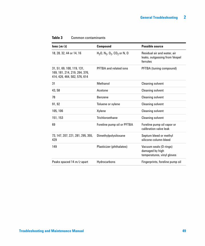
Table 3 lists some of the more common contaminants, the ions characteristic of those contaminants, and the likely sources of those contaminants.
Troubleshooting and Maintenance Manual
General Troubleshooting 2
Troubleshooting and
Table 3 Common contaminants
Ions (m/z) Compound Possible source
18, 28, 32, 44 or 14, 16 H2O, N2, O2, CO2 or N, O Residual air and water, air leaks, outgassing from Vespel ferrules
31, 51, 69, 100, 119, 131,169, 181, 214, 219, 264, 376, 414, 426, 464, 502, 576, 614
PFTBA and related ions PFTBA (tuning compound)
31 Methanol Cleaning solvent
43, 58 Acetone Cleaning solvent
78 Benzene Cleaning solvent
91, 92 Toluene or xylene Cleaning solvent
105, 106 Xylene Cleaning solvent
151, 153 Trichloroethane Cleaning solvent
69 Foreline pump oil or PFTBA Foreline pump oil vapor or calibration valve leak
73, 147, 207, 221, 281, 295, 355, 429
Dimethylpolysiloxane Septum bleed or methyl silicone column bleed
149 Plasticizer (phthalates) Vacuum seals (O-rings)damaged by high temperatures, vinyl gloves
Peaks spaced 14 m/z apart Hydrocarbons Fingerprints, foreline pump oil
Maintenance Manual 49

50
2 General Troubleshooting
Troubleshooting and Maintenance Manual
Agilent 7000 Series Triple Quadrupole GC/MS Troubleshooting and Maintenance Manual
3CI Troubleshooting
Common CI-Specific Problems 52
Troubleshooting Tips and Tricks 53
Air Leaks 54
Pressure-Related Symptoms 58
Signal-Related Symptoms 62
Tuning-Related Symptoms 70
This chapter outlines the troubleshooting of Agilent 7000 Triple Quad GC/MSs equipped with the chemical ionization (CI) source. Most of the troubleshooting information in the previous chapter also applies to CI Triple Quads.
51Agilent Technologies
3 CI Troubleshooting
Common CI-Specific Problems
52
Because of the added complexity of the parts required for CI, there are many potential problems added. By far the greatest number and most serious problems with CI are associated with leaks or contamination in the reagent gas introduction system. NCI is especially sensitive to the presence of air; leaks small enough to cause no problems in PCI can destroy NCI sensitivity.
As with EI, if the MS tunes well and no air leak is present, sample sensitivity problems should be addressed by GC inlet maintenance first.
• Wrong reagent gas
• Reagent gas not hooked up or hooked up to wrong reagent gas inlet port
• Wrong ions entered in tune file
• Wrong tune file selected
• Not enough bakeout time has elapsed since vent (background is too high)
• Wrong column positioning (extending > 2 mm past tip of interface)
• Interface tip seal not installed
• EI source installed in CI mode
• EI filament or other EI source parts in CI ion source
• Air leaks in reagent gas flow path
• CI filament has stretched and sagged:
• High EMV
• Linear (no inflection point) electron energy (EIEnrgy) ramp
Troubleshooting and Maintenance Manual
CI Troubleshooting 3
Troubleshooting Tips and Tricks
Rule 1: “Look for what has been changed.”
Troubleshooting and
Many problems are introduced accidentally by human actions. Every time any system is disturbed, there is a chance of introducing a new problem.
• If the MS was just pumped down after maintenance, suspect air leaks or incorrect assembly.
• If the reagent gas bottle or gas purifier were just changed, suspect leaks or contaminated or incorrect gas.
• If the GC column was just replaced, suspect air leaks or contaminated or bleeding column.
• If you have just switched ion polarity or reagent gas, suspect the tune file you have loaded in memory. Is it the appropriate file for your mode of operation?
Rule 2: “If complex isn’t working, go back to simple.”
A complex task is not only more difficult to perform, but also more difficult to troubleshoot as well. For example, CI requires more parts to work correctly than EI does.
• If you’re having trouble with NCI, verify that PCI still works.
• If you’re having trouble with other reagent gases, verify that methane still works.
• If you’re having trouble with CI, verify that EI still works.
Rule 3: “Divide and conquer.”
This technique is known as “half-split” troubleshooting. If you can isolate the problem to only part of the system, it is much easier to locate.
• To isolate an air leak, select Shutoff valve. If abundance of m/z 32 decreases, the problem is not in the flow module.
Maintenance Manual 53

3 CI Troubleshooting
Air Leaks
How do I know if I have an air leak?
54
Large air leaks can be detected by vacuum symptoms: loud gurgling noise from the foreline pump, inability of the turbo pump to reach 95% speed, or, in the case of smaller leaks, high pressure readings on the high vacuum gauge controller.
The mass flow controller is calibrated for methane and the high vacuum gauge controller is calibrated for nitrogen, so measurements are not accurate in absolute terms:
Familiarize yourself with the measurements on your system under operating conditions. Watch for changes that may indicate a vacuum or gas flow problem.
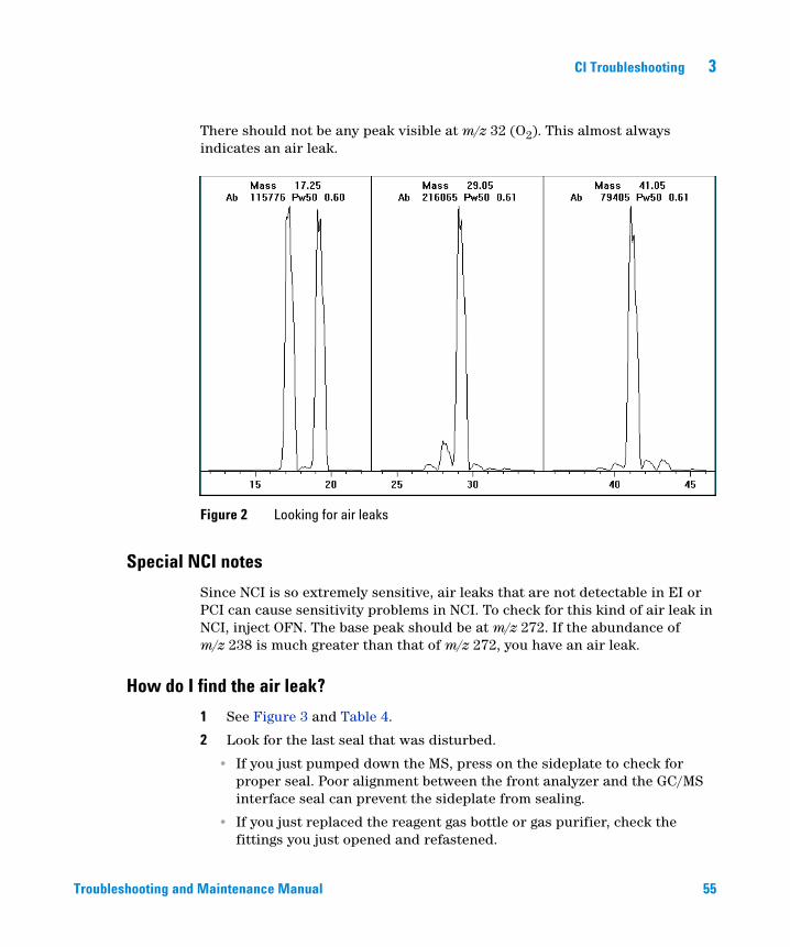
Always look for small air leaks when setting up methane flow. Run the methane pretune, starting with a good PCI tune file (Figure 2). The abundance of m/z 19 (protonated water) should be less than 50% of m/z 17 for acceptable PCI performance. For NCI, the abundance of m/z 19 (protonated water) should be less than 25% that of m/z 17. If the MS was just pumped down, look for the abundance of m/z 19 to be decreasing.
Troubleshooting and Maintenance Manual
CI Troubleshooting 3
Troubleshooting and
There should not be any peak visible at m/z 32 (O2). This almost always indicates an air leak.
Figure 2 Looking for air leaks
Special NCI notes
Since NCI is so extremely sensitive, air leaks that are not detectable in EI or PCI can cause sensitivity problems in NCI. To check for this kind of air leak in NCI, inject OFN. The base peak should be at m/z 272. If the abundance of m/z 238 is much greater than that of m/z 272, you have an air leak.
How do I find the air leak?
1 See Figure 3 and Table 4.
2 Look for the last seal that was disturbed.
• If you just pumped down the MS, press on the sideplate to check for proper seal. Poor alignment between the front analyzer and the GC/MS interface seal can prevent the sideplate from sealing.
• If you just replaced the reagent gas bottle or gas purifier, check the fittings you just opened and refastened.
Maintenance Manual 55
56
3 CI Troubleshooting
3 Check for tightness of seals at GC inlet and interface column nuts. Ferrules for capillary columns often loosen after several heat cycles. Do not overtighten the interface nut.
4 If any of the fittings inside the flow module (VCR fittings) were loosened and then retightened, the gasket must be replaced. These gaskets are good for one use only.
CAUTION Do not loosen the nuts on any VCR fittings unless you intend to replace the gaskets. Otherwise, you will create an air leak.
5 Remember that most small air leaks visible in CI mode are located in either the carrier gas or reagent gas flow paths. Leaks into the analyzer chamber are not likely to be seen in CI because of the higher pressure inside the ionization chamber.
6 Half-split the system.
• Close valves starting at the gas select valves (Gas A, then Gas B), then close the shutoff valve. See Figure 3 and Table 4.
• Cool and vent the MS, remove the GC column, and cap off the interface.
If you use argon or other introduced gas to find air leaks, this does not work well for the reagent gas flow system. It takes as long as 15 minutes for the peak to reach the ion source if the leak is at the inlet to the flow module.
Troubleshooting and Maintenance Manual
CI Troubleshooting 3
Troubleshooting and
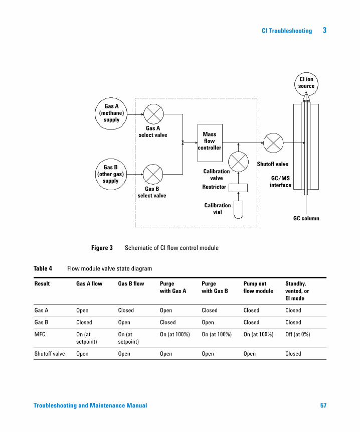
Figure 3 Schematic of CI flow control module
Gas A(methane)
supply
Gas B(other gas)
supply
Gas Aselect valve
Gas Bselect valve
Massflow
controller
Calibrationvalve
Restrictor
Calibrationvial
Shutoff valve
GC/MSinterface
GC column
CI ionsource
Table 4 Flow module valve state diagram
Result Gas A flow Gas B flow Purge with Gas A
Purge with Gas B
Pump outflow module
Standby, vented, orEI mode
Gas A Open Closed Open Closed Closed Closed
Gas B Closed Open Closed Open Closed Closed
MFC On (at setpoint)
On (at setpoint)
On (at 100%) On (at 100%) On (at 100%) Off (at 0%)
Shutoff valve Open Open Open Open Open Closed
Maintenance Manual 57
3 CI Troubleshooting
Pressure-Related Symptoms
58
The following symptoms are all related to high vacuum pressure. Each symptom is discussed in more detail in the following pages.
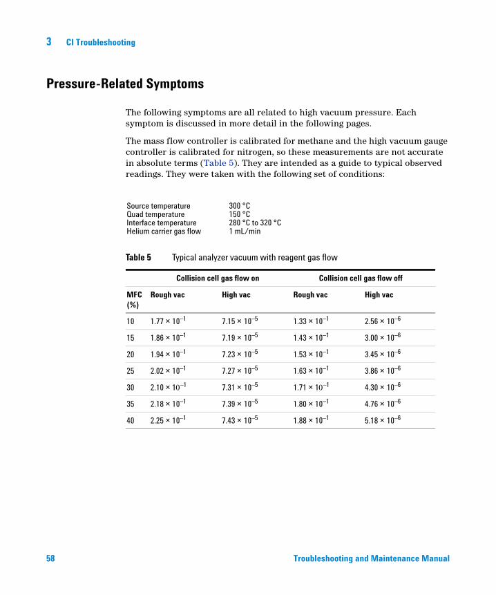
The mass flow controller is calibrated for methane and the high vacuum gauge controller is calibrated for nitrogen, so these measurements are not accurate in absolute terms (Table 5). They are intended as a guide to typical observed readings. They were taken with the following set of conditions:
Source temperature 300 °CQuad temperature 150 °CInterface temperature 280 °C to 320 °CHelium carrier gas flow 1 mL/min
Table 5 Typical analyzer vacuum with reagent gas flow
Collision cell gas flow on Collision cell gas flow off
MFC (%)
Rough vac High vac Rough vac High vac
10 1.77 ×10⁻¹ 7.15 ×10⁻⁵ 1.33 ×10⁻¹ 2.56 ×10⁻⁶
15 1.86 ×10⁻¹ 7.19 ×10⁻⁵ 1.43 ×10⁻¹ 3.00 ×10⁻⁶
20 1.94 ×10⁻¹ 7.23 ×10⁻⁵ 1.53 ×10⁻¹ 3.45 ×10⁻⁶
25 2.02 ×10⁻¹ 7.27 ×10⁻⁵ 1.63 ×10⁻¹ 3.86 ×10⁻⁶
30 2.10 ×1–1 7.31 ×10⁻⁵ 1.71 ×1–1 4.30 ×10⁻⁶
35 2.18 ×10⁻¹ 7.39 ×10⁻⁵ 1.80 ×10⁻¹ 4.76 ×10⁻⁶
40 2.25 ×10⁻¹ 7.43 ×10⁻⁵ 1.88 ×10⁻¹ 5.18 ×10⁻⁶
Troubleshooting and Maintenance Manual
CI Troubleshooting 3
Poor vacuum without reagent gas flow
Troubleshooting and
Excess water in the background
Scan from 10 to 40 m/z. A large peak at m/z 19 (>m/z 17) indicates water in the background. If water is present, allow the instrument to bake out more and flow reagent gas through the lines to purge any accumulated water.
Air leak
Run Methane Pretune. See the Operation Manual. A visible peak at m/z 32 indicates air in the system. Check for and correct any leaks. See “Air Leaks” on page 54.
The foreline pump is not working properly
For the standard foreline pump, replace the pump oil. If that does not help, or for the dry foreline pump, it may be necessary to replace the pump. Contact your local Agilent Technologies Customer Engineer.
The turbo pump is not working properly
Check the pump speed. It should be at least 95%. Contact your local Agilent Technologies service representative.
CAUTION Use of ammonia as reagent gas can shorten the life of the foreline pump oil (with standard pump) and possibly of the foreline pump itself. See “To Minimize Foreline Pump Damage from Ammonia” on page 116.
Maintenance Manual 59
3 CI Troubleshooting
High pressure with reagent gas flow
60
The reagent gas flow rate is too high
On the flow controller, turn down reagent gas flow as appropriate. Verify that reagent ion ratios are correct.
Air leak
Run Methane Pretune. See the Operation Manual. Visible peak at m/z 32 indicates air in the system. Check for and correct any leaks. See the “Air Leaks” on page 54.
Interface tip seal is not installed
Check the source storage box. If the seal is not in the box, vent the MS and verify that the seal is correctly installed.
Troubleshooting and Maintenance Manual
CI Troubleshooting 3
Pressure does not change when reagent flow is changed
Troubleshooting and
The reagent gas regulator is closed
Check and, if necessary, open the reagent gas regulator.
The reagent gas regulator is set to the wrong pressure
Set the reagent gas regulator to 20-25 psi (140-175 kPa) for methane or to 3 to 10 psi (20 to 70 kPa) for isobutane or ammonia.
The valve on the reagent gas bottle is closed
Check and, if necessary, open the valve on the reagent gas bottle.
The reagent gas supply is empty
Check and, if necessary, replace the reagent gas supply.
Reagent lines kinked, bent, pinched, or disconnected
Inspect the reagent lines and repair any defects. Check especially to make sure the reagent line is connected to the rear of the flow module. Be sure the methane line is connected to the Gas A inlet.
GC/MS interface clogged or damaged
Check for flow and repair or replace components as indicated.
Maintenance Manual 61
3 CI Troubleshooting
Signal-Related Symptoms
62
This section describes symptoms related to the signal. The symptom may be too much signal, too little signal, a noisy signal, or an incorrect signal. Signal-related symptoms are generally observed during tuning but may also be observed during data acquisition.
Error messages in autotune due to insufficient signal may vary.
The following symptoms are covered in more detail in this section:
• No peaks. See page 62.
• No or low reagent gas signal. See page 64.
• No or low PFDTD signal. See page 66.
• Excessive noise. See page 67.
• Low signal-to-noise ratio. See page 67.
• Large peak at m/z 19. See page 68.
• Peak at m/z 32. See page 69.
No peaks
When troubleshooting “no peaks” it is important to specify what mode of operation is being used and what expected peaks are not being seen. Always start with methane PCI and verify presence of reagent ions.
No reagent gas peaks in PCI
If MS has been working well and nothing seems to have been changed
• Wrong tune file loaded, or tune file corrupted
• Wrong ion polarity (there are no reagent ions visible in NCI)
• No reagent gas flow; look for background ions and check pressure
• Wrong reagent gas selected for the tune file (looking for wrong ions)
• Large air leak
• Dirty ion source
• Poor vacuum (pump problem). See page 58.
Troubleshooting and Maintenance Manual
CI Troubleshooting 3
Troubleshooting and
If MS was recently switched from EI to CI
• Interface tip seal not installed
• No reagent gas flow
• Analyzer not sealed (big air leak)
• Wrong tune file loaded or tune file corrupted
• Ion source not assembled or connected correctly
• Wrong reagent gas selected for the tune file (looking for wrong ions)
No PFDTD peaks in PCI
• Incorrect reagent gas. There are no PCI PFDTD peaks created with isobutane or ammonia. Switch to methane.
• Analyzer not sealed (big air leak)
• No calibrant in vial
• Defective calibration valve(s)
• Air leak in carrier or reagent gas path
No reagent gas peaks in NCI
• Reagent gases do not ionize in NCI; look for background ions instead
• Verify tune parameters
• If no background ions are visible, go back to methane PCI
No PFDTD calibrant peaks in NCI
• Look for background ions: 17 (OH–), 35 (Cl–), and 235 (ReO3–)
• Verify tune parameters
• Go back to methane PCI
No sample peaks in NCI
• Look for background ions: 17 (OH–), 35 (Cl–), and 235 (ReO3–)
• Go back to methane PCI
• Poor quality reagent gas (purity less than 99.99%)
Large peak at m/z 238 in NCI OFN spectrum
• Look for background ions: 17 (OH–), 35 (Cl–), and 235 (ReO3–)
• Find and fix your small air leak
Maintenance Manual 63
3 CI Troubleshooting
No or low reagent gas signal
64
If you have just installed the CI ion source and have an air leak or large amounts of water in the system and have run one or more autotunes, the ion source is probably dirty now.
Fix the air leak. Clean the ion source. Then bake out for two hours before tuning. See the Operation Manual.
The wrong reagent gas is flowing.
Turn on the correct reagent gas for your tune file.
Ion polarity is set to Negative. No reagent gas ions are formed in NCI.
Switch to Positive ionization mode.
The reagent gas flow is set too low.
Increase the reagent gas flow.
Reagent gas supply tubing is blocked, kinked, pinched, or disconnected.
Inspect and, if necessary, repair or replace the reagent gas supply tubing.
Wrong filament wires are connected to filament.
Make sure that the filament 1 wires are connected to the CI ion source filament and that the filament 2 wires are connected to the dummy filament.
Carbon has built up on the filament or filament has sagged out of alignment.
Inspect the filament. If necessary, replace the filament.
Too much air or water in the system.
Run the methane pretune. Peaks at m/z 32 and 19 usually indicate air and water, respectively. Bake out and purge the instrument until there is no visible peak at m/z 32 and the peak at m/z 19 is reduced to a very low level. If the peak at m/z 32 does not decrease, an air leak is likely. See “Air Leaks” on page 54 for more information.
Troubleshooting and Maintenance Manual
CI Troubleshooting 3
Troubleshooting and
The signal cable is not connected.
Check and, if necessary, reconnect the signal cable.
The filament or filament support is shorted to the ion source body or repeller.
Inspect the filament. If necessary, realign the filament support arms.
The electron inlet hole is blocked.
Inspect the electron inlet hole. If necessary, clean the hole with a clean toothpick and a slurry of aluminum oxide powder and methanol. If the electron inlet hole is that dirty, the entire ion source probably needs to be cleaned. See Chapter 4, “General Maintenance” on page 75 for more information.
Ion source wires are not connected, or incorrectly connected.
Inspect the repeller. Make sure the repeller lead is firmly attached to the repeller. Inspect the wires to the ion focus and entrance lenses. If the connections are reversed, correct the problem.
One of the detector leads (in the analyzer chamber) is not connected.
Check and, if necessary, reconnect the electron multiplier leads.
Saturated methane/isobutane gas purifier
Replace the gas purifier.
Poor quality methane (purity below 99.99%)
Replace the methane with high-purity methane. If necessary, clean and purge the reagent gas lines and clean the ion source.
Maintenance Manual 65
3 CI Troubleshooting
No or low PFDTD signal, but reagent ions are normal
66
You are using any reagent gas but methane in PCI.
Switch to methane.
Wrong or corrupted tune file loaded
Check your tune file.
No PFDTD in the calibrant vial
Inspect the calibration vial on the back of the flow controller. If necessary, fill the vial with PFDTD. Do not fill the vial completely; keep the level at least 0.5 cm from the top of the vial.
The pressure of the methane entering the flow controller is too high.
Make sure the regulator on the methane supply is set to 10 psig (70 kPa).
The CI ion source is dirty.
Clean the ion source. See Chapter 5, “CI Maintenance” on page 115 for more information.
The calibration valve was not purged after the vial was refilled.
Purge the calibration valve as described in “To refill/purge the EI calibration vial” on page 89. Then clean the ion source.
The calibrant vial was overfilled. Excess PFDTD can quench the chemical ionization reactions.
Check the level of the PFDTD in the calibration vial. It should be below the end of the inside tube in the vial.
Poor quality methane (purity below 99.99%)
Replace the methane with high-purity methane. If necessary, clean and purge the reagent gas lines and clean the ion source.
Troubleshooting and Maintenance Manual
CI Troubleshooting 3
Excessive noise or low signal-to-noise ratio
Troubleshooting and
The GC inlet needs maintenance.
Refer to the GC manual.
The CI ion source is dirty.
Clean the ion source. See the Agilent 7000 Triple Quad GC/MS Operation Manual for more information.
Poor vacuum
Check the pressure on the high vacuum gauge controller.
Air leak
Run Methane Pretune (in PCI). Large peak at m/z 32 indicates air in the system. Check for and correct any leaks. See “Air Leaks” on page 54.
Saturated methane/isobutane gas purifier
Replace the gas purifier.
Poor quality methane (purity below 99.99%)
Replace the methane with high-purity methane. If necessary, clean and purge the reagent gas lines and clean the ion source.
Reagent gas flows too high (in EI/PCI MSs)
Verify that the reagent gas setup is correct.
Maintenance Manual 67
3 CI Troubleshooting
Large peak at m/z 19
68
If the abundance of the peak at m/z 19 is more than half abundance of the peak at m/z 17, then there is probably too much water in the system.
The system was not baked out sufficiently after it was last vented.
Bake out the system as described in Chapter 4, “General Maintenance” on page 75.
Moisture left over in the reagent gas supply tubing and flow module
Purge the reagent gas supply lines for at least 60 minutes.
Contaminated reagent gas supply
Replace the reagent gas supply and purge the lines and flow module.
Saturated methane/isobutane gas purifier
Replace the gas purifier.
Troubleshooting and Maintenance Manual
CI Troubleshooting 3
Peak at m/z 32
Troubleshooting and
A visible peak at m/z 32 in methane pretune often indicates air in the system.
Residual air from recent venting — check for water indicated by a large peak at m/z 19.
Bake out the system under vacuum to eliminate water.
New or dirty reagent gas supply tubing
Purge the reagent gas supply lines and flow module for at least 60 minutes. See the Operation Manual.
Air leak
Check for leaks and correct any that you find. See “Air Leaks” on page 54. After all leaks have been corrected, clean the ion source.
Contaminated reagent gas supply. Suspect this if you have recently replaced your gas tank, and you have ruled out air leaks.
Replace the reagent gas supply.
The capillary column is broken or disconnected.
Inspect the capillary column. Make sure it is not broken and it is installed correctly.
Saturated methane/isobutane gas purifier
Replace the gas purifier.
Maintenance Manual 69
3 CI Troubleshooting
Tuning-Related Symptoms
70
This section describes symptoms related to tuning. Most symptoms involve difficulties with tuning or with the results of tuning. The following symptoms are covered in this section:
• CI ion ratio is difficult to adjust or unstable
• High electron multiplier voltage
• Cannot complete autotune
• Peak widths are unstable
Troubleshooting and Maintenance Manual
CI Troubleshooting 3
Reagent gas ion ratio is difficult to adjust or unstable
Troubleshooting and
The interface tip seal is incorrectly placed, damaged, or missing.
Inspect the interface tip seal. If necessary, remove and reinstall it to ensure a good seal with the CI ion source. Replace it if it is damaged. Install it if it is missing.
Residual air and water in the MS or in the reagent gas supply lines
Run the methane pretune. Air will appear as a peak at m/z 32 and excessive water as a peak at m/z 19 > m/z 17. If either of these conditions is present, purge the reagent gas supply lines and bake out the MS. Continued presence of a large peak at m/z 32 may indicate an air leak. After correcting the problems, you may need to clean the ion source.
Air leak
Run Methane Pretune (in PCI). Large peak at m/z 32 indicates air in the system. Check for and correct any leaks. See “Air Leaks” on page 54.
The reagent gas supply is at the wrong pressure.
Check the regulator on the reagent gas supply. It should be adjusted to 20 psi (140 kPa).
A leak in the reagent gas delivery path. This is especially likely if you have set the methane flow much higher than normal and the ratio is still too low.
Check the reagent gas path. Tighten fittings.
The CI ion source is dirty.
Clean the ion source. See the Operation Manual for more information.
Maintenance Manual 71
3 CI Troubleshooting
High electron multiplier voltage
72
The electron multiplier voltage can range from a few hundred volts to 3000 V. If the CI autotune program consistently sets the electron multiplier voltage at or above 2600 V but can still find peaks and complete the tune, it may indicate a problem.
The filament is worn out.
The CI filament may wear out without actually breaking. Check the Electron Energy ramp; the curve should have a definite maximum with an inflection point. If the curve is linear with a positive slope and no inflection point, and the EMV is high, the filament has stretched to the point where it does not line up with the hole in the ion source body, and most electrons are not getting into the source.
Replace the filament.
The analyzer is not at the proper operating temperature.
Verify the ion source and quadrupole temperatures. The default source temperature is 250 °C for PCI and 150 °C for NCI. The quadrupole temperature is 150 °C for both CI modes.
The CI ion source is dirty.
Clean the ion source. See Operation Manual for more information.
The electron multiplier (detector) is failing. Switch to EI mode and confirm.
Replace the electron multiplier.
Troubleshooting and Maintenance Manual
CI Troubleshooting 3
Cannot complete Autotune
Troubleshooting and
Wrong or corrupted tune file
Check the tune parameters.
The m/z 28/27 ion ratio (for methane) is incorrect. The correct ratio should be between 1.5 and 5.0.
If the ion ratio is incorrect, adjust it. See the Operation Manual.
The CI ion source is dirty.
Clean the ion source. See Operation Manual for more information.
Too much air or water in the system
See “Air Leaks” on page 54. After eliminating these problems, clean the ion source.
Maintenance Manual 73
3 CI Troubleshooting
Peak widths are unstable
74
Wrong or corrupted tune file
Check the tune parameters.
The CI ion source is dirty.
Clean the ion source. See Chapter 5, “CI Maintenance” on page 115 for more information.
Air leak
Run Methane Pretune (in PCI). A visible peak at m/z 32 indicates air in the system. Check for and correct any leaks. See “Air Leaks” on page 54. After eliminating all air leaks, clean the ion source.
Troubleshooting and Maintenance Manual
Agilent 7000 Series Triple Quadrupole GC/MS Troubleshooting and Maintenance Manual
4General Maintenance
Before Starting 76
Maintaining the Mainframe 80
Maintaining the Vacuum System 90
Maintaining the Foreline Pump 94
Maintaining the Analyzers and Collision Cell 105
Maintaining the Electronics 110
75Agilent Technologies
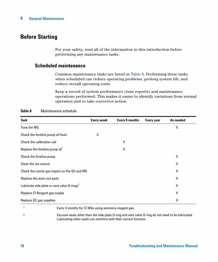
4 General Maintenance
Before Starting
76
For your safety, read all of the information in this introduction before performing any maintenance tasks.
Scheduled maintenance
Common maintenance tasks are listed in Table 6. Performing these tasks when scheduled can reduce operating problems, prolong system life, and reduce overall operating costs.
Keep a record of system performance (tune reports) and maintenance operations performed. This makes it easier to identify variations from normal operation and to take corrective action.
Table 6 Maintenance schedule
Task Every week Every 6 months Every year As needed
Tune the MS X
Check the foreline pump oil level X
Check the calibration vial X
Replace the foreline pump oil* X
Check the foreline pump X
Clean the ion source X
Check the carrier gas trap(s) on the GC and MS X
Replace the worn out parts X
Lubricate side plate or vent valve O-rings† X
Replace CI Reagent gas supply X
Replace GC gas supplies X
* Every 3 months for CI MSs using ammonia reagent gas.
† Vacuum seals other than the side plate O-ring and vent valve O-ring do not need to be lubricated. Lubricating other seals can interfere with their correct function.
Troubleshooting and Maintenance Manual
General Maintenance 4
Tools, spare parts, and supplies
Troubleshooting and
Some of the required tools, spare parts, and supplies are included in the GC shipping kit, MS shipping kit, or MS tool kit. You must supply others yourself. Each maintenance procedure includes a list of the materials required for that procedure.
High voltage precautions
Whenever the MS is plugged in, even if the power switch is off, potentially dangerous voltage (120 VAC or 200/240 VAC) exists on the wiring and fuses between where the power cord enters the instrument and the power switch.
When the power switch is on, potentially dangerous voltages exist on:
• Electronic circuit boards
• Toroidal transformer
• Wires and cables between these boards
• Wires and cables between these boards and the connectors on the back panel of the MS
• Some connectors on the back panel (for example, the foreline power receptacle)
Normally, all of these parts are shielded by safety covers. As long as the safety covers are in place, it should be difficult to accidentally make contact with dangerous voltages.
Perform no maintenance with the MS turned on or plugged into its power source
WARNINGunless you are instructed to do so by one of the procedures in this chapter.Some procedures in this chapter require access to the inside of the MS while the power switch is on. Do not remove any of the electronics safety covers in any of these procedures. To reduce the risk of electric shock, follow the procedures carefully.
Dangerous temperatures
Many parts in the MS operate at, or reach, temperatures high enough to cause serious burns. These parts include, but are not limited to:• GC/MS interface
• Analyzer parts
• Vacuum pumps
Maintenance Manual 77
78
4 General Maintenance
Never touch these parts while your MS is on. After the MS is turned off, give these
WARNINGparts enough time to cool before handling them.WARNING The GC/MS interface heater is powered by a heated zone on the GC. The interface heater can be on, and at a dangerously high temperature, even though the MS is off. The GC/MS interface is well insulated. Even after it is turned off, it cools very slowly.
WARNING The foreline pump can cause burns if touched when operating. An optional safety shield will prevent you from touching it.
The GC inlets and GC oven also operate at very high temperatures. Use the same caution around these parts. See the documentation supplied with your GC for more information.
Chemical residue
Only a small portion of your sample is ionized by the ion source. The majority of any sample passes through the ion source without being ionized. It is pumped away by the vacuum system. As a result, the exhaust from the foreline pump will contain traces of the carrier gas and your samples. Exhaust from the foreline pump also contains tiny droplets of foreline pump oil.
An oil trap is supplied with the foreline pump. This trap stops only pump oil droplets. It does not trap any other chemicals. If you are using toxic solvents or analyzing toxic chemicals, do not use this oil trap. For all foreline pumps, install a hose to take the exhaust from the foreline pump outdoors or into a fume hood vented to the outdoors. For the foreline pump, this requires removing the oil trap. Be sure to comply with your local air quality regulations.
The oil trap supplied with the foreline pump stops only foreline pump oil. It does not
WARNINGtrap or filter out toxic chemicals. If you are using toxic solvents or analyzing toxic chemicals, remove the oil trap.Troubleshooting and Maintenance Manual
General Maintenance 4
Troubleshooting and
The fluid in the foreline pump also collects traces of the samples being analyzed. All used pump fluid should be considered hazardous and handled accordingly. Dispose of used fluid as specified by your local regulations.
Electrostatic discharge
WARNING When replacing pump fluid, use appropriate chemical-resistant gloves and safety glasses. Avoid all contact with the fluid.
All of the printed circuit boards in the MS contain components that can be damaged by electrostatic discharge (ESD). Do not handle or touch these boards unless absolutely necessary. In addition, wires, contacts, and cables can conduct ESD to the electronics boards to which they are connected. This is especially true of the mass filter (quadrupole) contact wires, which can carry ESD to sensitive components on the quadrupole board. ESD damage may not cause immediate failure, but it will gradually degrade the performance and stability of your MS.
When you work on or near printed circuit boards or when you work on components with wires, contacts, or cables connected to printed circuit boards, always use a grounded antistatic wrist strap and take other antistatic precautions. The wrist strap should be connected to a known good earth ground. If that is not possible, it should be connected to a conductive (metal) part of the assembly being worked on, but not to electronic components, exposed wires or traces, or pins on connectors.
Take extra precautions, such as a grounded antistatic mat, if you must work on components or assemblies that have been removed from the MS. This includes the analyzer.
CAUTION To be effective, an antistatic wrist strap must fit snugly (not tight). A loose strap provides little or no protection.
Antistatic precautions are not 100% effective. Handle electronic circuit boards as little as possible and then only by the edges. Never touch components, exposed traces, or pins on connectors and cables.
Maintenance Manual 79
4 General Maintenance
Maintaining the Mainframe
80
The mainframe consists of everything that does not fit in the vacuum, analyzer, interface, or electronics categories.
To remove the MS covers
Materials needed
• Screwdriver, Torx T-20 (8710-1615)
If you need to remove one of the MS covers (see Figure 4), follow these procedures:
WARNING The GC/MS interface, the analyzer parts, and the vacuum system operate at temperatures high enough to cause serious burns. Give these parts enough time to cool before accessing them or handling them.
To remove the front right analyzer window cover
1 Pull the window towards you. The cover is held in place by magnets.
2 Lift the window forward and off the MS.
To remove the front bottom cover
Grasp the cover on both sides and pull the cover forward.
To open the left side panel
Pull gently on the front left window and allow the left side panel to swing forward and down.
To remove the left rear cover
1 Open the left side panel.
2 Remove the top screw from the rear cover.
3 Lift the bottom flap of the cover out of the groove in the back of the MS to free the cover.
Troubleshooting and Maintenance Manual
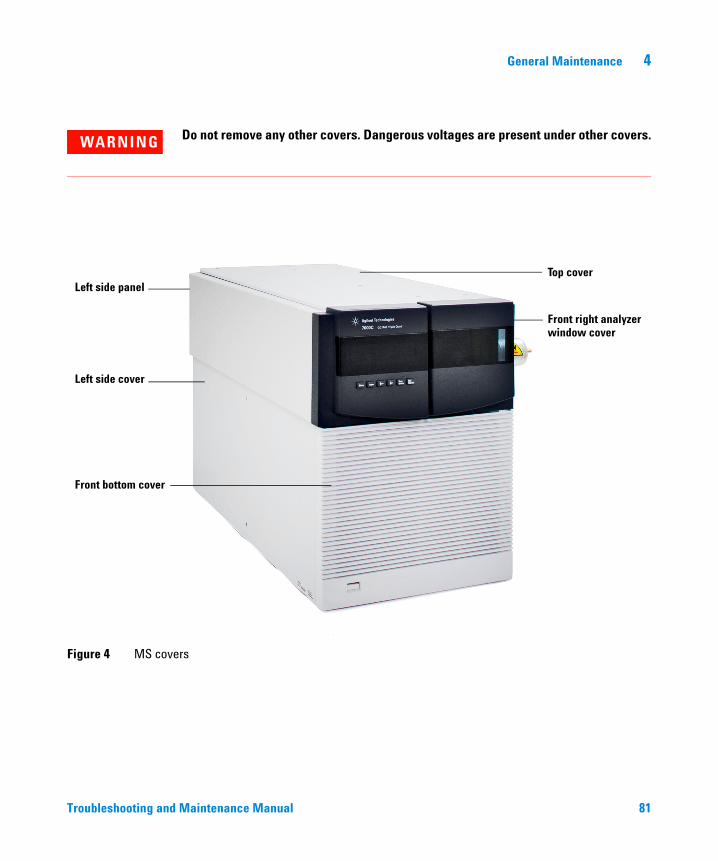
General Maintenance 4
Troubleshooting and
WARNING Do not remove any other covers. Dangerous voltages are present under other covers.
Figure 4 MS covers
Left side panel
Front bottom cover
Left side cover
Top cover
Front right analyzerwindow cover
Maintenance Manual 81
4 General Maintenance
To move or store the MS
82
Materials needed
• Ferrule, blank (5181-3308)
• Interface column nut (05988-20066)
• Wrench, open-end, 1/4-inch × 5/16-inch (8710-0510)
Procedure
WARNING Make sure the GC/MS interface and the analyzer zones are cool (below 100 °C) before you vent the MS. A temperature of 100 °C is hot enough to burn skin; always wear cloth gloves when handling analyzer parts.
WARNING If you are using hydrogen as a carrier gas, the carrier gas flow must be off before turning off the MS power. If the foreline pump is off, hydrogen will accumulate in the MS and an explosion may occur. Read “Hydrogen Safety” before operating the MS with hydrogen carrier gas.
WARNING When the MS is vented, do not put the MassHunter Workstation software into Instrument Control view. Doing so will turn on the interface heater.
CAUTION Be sure the GC oven and the GC/MS interface are cool before turning off the carrier gas flow.
CAUTION Never vent the MS by allowing air in through either end of the foreline hose. Use the vent valve or remove the column nut and column.
Do not vent while the turbo pump is still spinning at more than 50%.
Do not exceed the maximum recommended total gas flow. See Table 2.
1 Vent the MS. See the Agilent 7000 Triple Quad GC/MS Operation Manual.
Troubleshooting and Maintenance Manual
General Maintenance 4
Troubleshooting and
2 Remove the column.
3 Disconnect the collision gas supply tubing.
4 Install a plug on the end of the collision gas tubing that leads into the analyzer chamber.
5 Move the MS away from the GC.
6 Unplug the GC/MS interface heater cable from the GC.
7 Remove the front analyzer window and open the left side analyzer panel. See “To remove the MS covers” on page 80.
8 Finger-tighten the side plate thumbscrews for both analyzers. (Figure 5).
CAUTION Do not overtighten the side plate thumbscrews. Overtightening will strip the threads in the analyzer chamber. It will also warp the side plate and cause leaks.
CAUTION Always wear clean gloves while handling any parts that go inside the analyzer chambers.
9 Switch the MS on to establish a rough vacuum.
10 When you hear the hissing sound of the pumpdown, close the vent valve. Continue the pumpdown for 2 to 3 minutes.
11 Switch the MS off.
12 Close the analyzer cover and replace the front analyzer window.
13 Disconnect the LAN, remote, and power cable.
Maintenance Manual 83
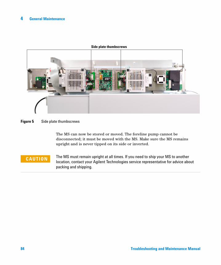
84
4 General Maintenance
Figure 5 Side plate thumbscrews
Side plate thumbscrews
The MS can now be stored or moved. The foreline pump cannot be disconnected; it must be moved with the MS. Make sure the MS remains upright and is never tipped on its side or inverted.
The MS must remain upright at all times. If you need to ship your MS to another
CAUTIONlocation, contact your Agilent Technologies service representative for advice about packing and shipping.Troubleshooting and Maintenance Manual
General Maintenance 4
To separate/connect the MS and the GC
Troubleshooting and
Materials needed
• Wrench, open-end, 1/4-inch × 5/16-inch (8710-0510)
Separation
WARNING Make sure the GC/MS interface and the analyzer zones are cool (below 100 °C) before you vent the MS. A temperature of 100 °C is hot enough to burn skin; always wear cloth gloves when handling analyzer parts.
WARNING If you are using hydrogen as a carrier gas, the carrier gas flow must be off before turning off the MS power. If the foreline pump is off, hydrogen will accumulate in the MS and an explosion may occur. Read “Hydrogen Safety” before operating the MS with hydrogen carrier gas.
CAUTION Be sure the GC oven and the GC/MS interface are cool before turning off carrier gas flow.
WARNING Make sure the GC/MS interface and GC oven have cooled before you remove the column.
1 Vent the MS. See the Agilent 7000 Triple Quad GC/MS Operation Manual.
2 Turn off the GC.
3 Remove the capillary column from the GC/MS interface.
4 The foreline pump may be located on the floor, on the lab bench next to or behind the MS, or under the analyzer chamber at the back of the MS. Move it as needed to provide slack in the tubing and cables.
5 Move the MS away from the GC until you have access to the GC/MS interface cable (Figure 6).
6 Place a column nut with a blank ferrule on the end of the interface. This will help keep contamination out of the MS.
Maintenance Manual 85
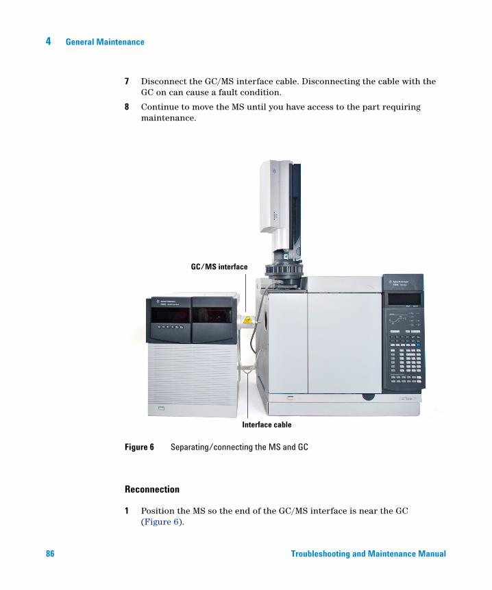
86
4 General Maintenance
7 Disconnect the GC/MS interface cable. Disconnecting the cable with the GC on can cause a fault condition.
8 Continue to move the MS until you have access to the part requiring maintenance.
Reconnection
1 Position the MS so the end of the GC/MS interface is near the GC (Figure 6).
Figure 6 Separating/connecting the MS and GC
GC/MS interface
Interface cable
Troubleshooting and Maintenance Manual
General Maintenance 4
Troubleshooting and
2 Reconnect the GC/MS interface cable.
3 Slide the MS to its regular position next to the GC.
Be careful not to damage the GC/MS interface as it passes into the GC. Make sure the end of the GC/MS interface extends into the GC oven.
4 The foreline pump may be located on the floor or on the lab bench next to or behind the MS.
5 Reinstall the capillary column.
6 Pump down the MS. See the Agilent 7000 Triple Quad GC/MS Operation Manual.
WARNING Make sure your MS meets all the conditions listed in the Pump Down section of the Agilent 7000 Triple Quad GC/MS Operation Manual before starting up and pumping down the MS. Failure to do so can result in personal injury.
CAUTION Do not turn on any GC heated zones until carrier gas flow is on. Heating a column with no carrier gas flow will damage the column.
CAUTION During pumpdown, do not push on the filament board safety cover while pressing on the analyzer boards. This cover was not designed to withstand this type of pressure.
7 Turn on the GC. Enter appropriate temperature setpoints for the GC/MS interface and GC oven.
Maintenance Manual 87
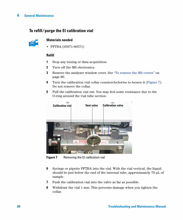
4 General Maintenance
To refill/purge the EI calibration vial
88
Materials needed
• PFTBA (05971-60571)
Refill
1 Stop any tuning or data acquisition.
2 Turn off the MS electronics.
3 Remove the analyzer window cover. See “To remove the MS covers” on page 80.
4 Turn the calibration vial collar counterclockwise to loosen it (Figure 7). Do not remove the collar.
5 Pull the calibration vial out. You may feel some resistance due to the O-ring around the vial tube section.
6 Syringe or pipette PFTBA into the vial. With the vial vertical, the liquid should be just below the end of the internal tube, approximately 70 µL of sample.
7 Push the calibration vial into the valve as far as possible.
8 Withdraw the vial 1 mm. This prevents damage when you tighten the collar.
Figure 7 Removing the EI calibration vial
Calibration vial Calibration valveVent valve
Troubleshooting and Maintenance Manual
General Maintenance 4
Maintaining the Vacuum System
Periodic maintenance
Troubleshooting and
As listed in Table 6, some maintenance tasks for the vacuum system must be performed periodically. These include:
• Checking the foreline pump fluid (every week)
• Checking the calibration vial (every 6 months)
• Replacing the foreline pump oil (every 6 months)
• Tightening the foreline pump oil box screws (first oil change after installation)
Failure to perform these tasks as scheduled can result in decreased instrument performance. It can also result in damage to your instrument.
Other procedures
Tasks such as replacing an ion vacuum gauge should be performed only when needed. See Chapter 2, “General Troubleshooting” on page 25 and see the online help in the MassHunter Workstation software for symptoms that indicate this type of maintenance is required.
More information is available
If you need more information about the locations or functions of vacuum system components, see “Vacuum System” on page 121.
Most of the procedures in this chapter are illustrated with video clips on the 7000 MS User Information DVD.
Maintenance Manual 89
4 General Maintenance
To remove/install the ion vacuum gauges
90
Each MS contains two ion vacuum gauges; one for the analyzer chamber pressure and one for the foreline pump entrance.
WARNING Make sure the GC/MS interface and the analyzer zones are cool (below 100 °C) before you vent the MS. A temperature of 100 °C is hot enough to burn skin; always wear cloth gloves when handling analyzer parts.
WARNING If you are using hydrogen as a carrier gas, the carrier gas flow must be off before turning off the MS power. If the foreline pump is off, hydrogen will accumulate in the MS and an explosion may occur. Read “Hydrogen Safety” before operating the MS with hydrogen carrier gas.
WARNING The turbo pump can cause burns if touched when operating. Make sure the pump has time to cool before touching.
CAUTION Never vent the MS by allowing air in through either end of the foreline hose. Use the vent valve or remove the column nut and column.
Do not vent while the turbo pump is still spinning at more than 50%.
Do not exceed the maximum recommended total gas flow. See Table 2.
WARNING Make sure your MS meets all the conditions listed in the Pump Down section of the Agilent 7000 Triple Quad GC/MS Operation Manual before starting up and pumping down the MS. Failure to do so can result in personal injury.
CAUTION During pumpdown, do not push on the filament board safety cover while pressing on the analyzer boards. This cover was not designed to withstand this type of pressure.
Troubleshooting and Maintenance Manual
General Maintenance 4
Troubleshooting and
Removal, foreline pump gauge
1 Vent the MS. See the Agilent 7000 Triple Quad GC/MS Operation Manual.
2 Separate the MS from the GC. See “To separate/connect the MS and the GC” on page 86.
3 Unplug the foreline gauge cable from the foreline gauge.
4 Unscrew the large wingnut on the gauge clamp. See Figure 8.
5 While supporting the gauge body, remove the clamp from the mounting flange.
6 Remove the gauge and hose together.
7 Loosen the hose clamp.
8 Pull the foreline gauge assembly out of the foreline hose.
Installation, foreline pump gauge
Installation is the reverse of the removal procedure.
Maintenance Manual 91
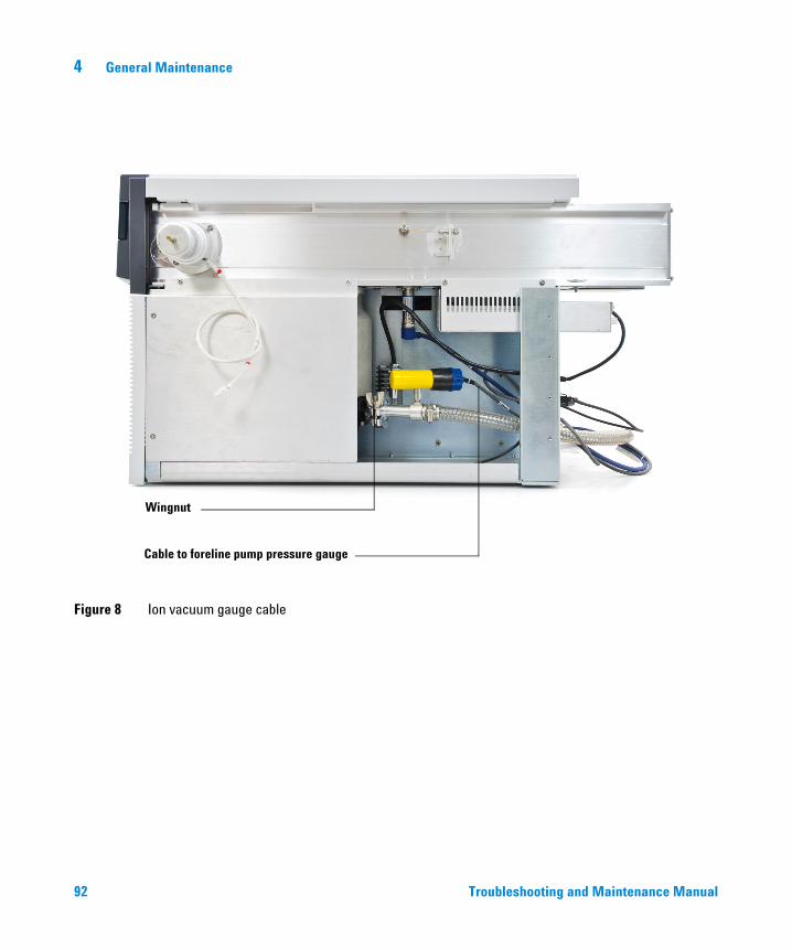
92
4 General Maintenance
Figure 8 Ion vacuum gauge cable
Cable to foreline pump pressure gauge
Wingnut
Troubleshooting and Maintenance Manual
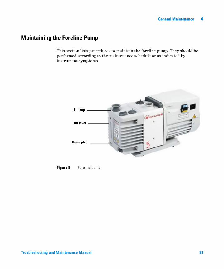
General Maintenance 4
Maintaining the Foreline Pump
Troubleshooting and
This section lists procedures to maintain the foreline pump. They should be performed according to the maintenance schedule or as indicated by instrument symptoms.
Figure 9 Foreline pump
Fill cap
Drain plug
Oil level
Maintena
nce Manual 93
4 General Maintenance
To check the foreline pump fluid level
94
Check the level and color of the pump fluid weekly.
1 Check the fluid level in the window of the foreline pump. The fluid level should be between the marks for Max and Min.
2 Check that the color of the pump fluid is clear or almost clear with few suspended particles. If the pump fluid is dark or full of suspended particles, replace it.
Never add or replace the foreline pump fluid while the pump is on.
CAUTIONRecord this procedure in the Maintenance Logbook.
NOTETroubleshooting and Maintenance Manual
General Maintenance 4
To add foreline pump fluid
Troubleshooting and
Add pump fluid when the pump fluid level is low.
Materials needed
• Funnel
• Gloves, chemical resistant, clean, lint free (p/n 9300-1751)
• Foreline pump fluid (Inland 45 oil, p/n 6040-0834)
• Safety glasses (goggles)
Never add pump fluid while the pump is on.
WARNINGThe fill cap and pump may be dangerously hot. Check that the fill cup and pump are
WARNINGcool before you touch them.Use only RV Fluid DS 45 type oil. Any other fluids can substantially reduce pump life
CAUTIONand invalidates the pump warranty.Procedure
1 Vent and turn off the instrument. See the Agilent 7000 Triple Quad GC/MS Operation Manual.
2 Unplug the instrument power cord from the electrical outlet.
3 Remove the fill cap on the foreline pump (see Figure 9).
4 Add new pump fluid until the fluid level is near, but not over the maximum mark beside the fluid level window (see Figure 9).
5 Reinstall the fill cap.
6 Wipe off all excess oil around and underneath of the pump.
7 Reconnect the power cord.
8 Start up the instrument. See the Agilent 7000 Triple Quad GC/MS Operation Manual.
Maintenance Manual 95
4 General Maintenance
To replace the foreline pump fluid
96
Replace the pump fluid every six months or sooner if the fluid appears dark or cloudy.
Materials needed
• Container for catching old pump fluid
• Funnel
• Gloves, chemical resistant, clean, lint free (p/n 9300-1751)
• Rough pump fluid (Inland 45 oil, p/n 6040-0834)
• Screwdriver, flat-bladed, large (p/n 8710-1029)
• Safety glasses (goggles)
Never add pump fluid while the pump is on.
WARNINGThe fill cap and pump may be dangerously hot. Check that the fill cap and pump are
WARNINGcool before you touch them.Do not touch the fluid. The residue from some samples are toxic. Properly dispose of
WARNINGthe fluid.Use only RV Fluid DS 45 type oil. Any other fluids can substantially reduce pump life
CAUTIONand invalidates the pump warranty.Procedure
1 Turn off the instrument. See the Agilent 7000 Triple Quad GC/MS Operation Manual
2 Unplug the power cord from the instrument.
3 Place a container under the drain plug of the foreline pump (see Figure 9).
Troubleshooting and Maintenance Manual
General Maintenance 4
Troubleshooting and
4 Remove the fill cap (see Figure 9), then open the drain plug. Drain the fluid completely by raising the motor end of the pump up.
5 Reinstall the drain plug.
6 Pour in new pump fluid until the fluid level is near, but not above the maximum mark beside the fluid level window (see Figure 9).
7 Reinstall the fill cap.
8 Reconnect the power cord.
9 Start up the instrument. See the Agilent 7000 Triple Quad GC/MS Operation Manual.
10 Pump down for 30 min, then inspect the pump for leaks.
11 Continue pumping down overnight and inspect the pump for leaks the next day.
The oil pan under the foreline pump can be a fire hazard
Oily rags, paper towels, and similar absorbents in the oil pan could ignite and damage the pump and other parts of the MS.
Combustible materials (or flammable/nonflammable wicking material) placed
WARNINGunder, over, or around the foreline (roughing) pump constitutes a fire hazard. Keep the pan clean, but do not leave absorbent material such as paper towels in it.Maintenance Manual 97
4 General Maintenance
To replace the fan for the turbo pump
98
Procedure
1 Vent the MS. See the Agilent 7000 Triple Quad GC/MS Operation Manual.
2 Turn the MS off.
3 Move the MS away from the GC to make the fan accessible.
4 Remove the fan plenum (four screws).
5 Disconnect the fan wiring from the extender cable (Figure 10).
6 Remove the four fan screws and the safety grill. Remove the fan. Keep the screws.
WARNING Do not touch the high vacuum pump. The pump could still be hot enough to burn you.
7 Connect the fan wiring to the new fan.
8 Install the new fan with the flow arrow on the side pointing toward the pump.
9 Add the safety grill and the four screws. Tighten the screws firmly.
WARNING Make sure the safety grill that shields the fan blades is in place.
10 Connect the fan wiring to the extender cable.
11 Pump down the MS. See the Agilent 7000 Triple Quad GC/MS Operation Manual.
Troubleshooting and Maintenance Manual
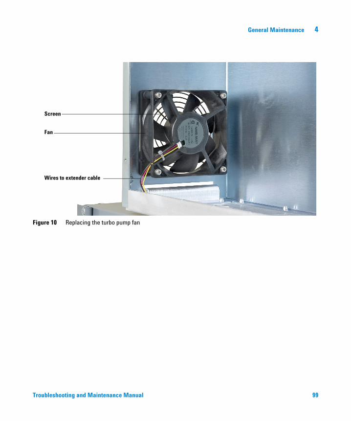
General Maintenance 4
Figure 10 Replacing the turbo pump fan
Fan
Screen
Wires to extender cable
Troubleshooting and Maintenance Manual 99
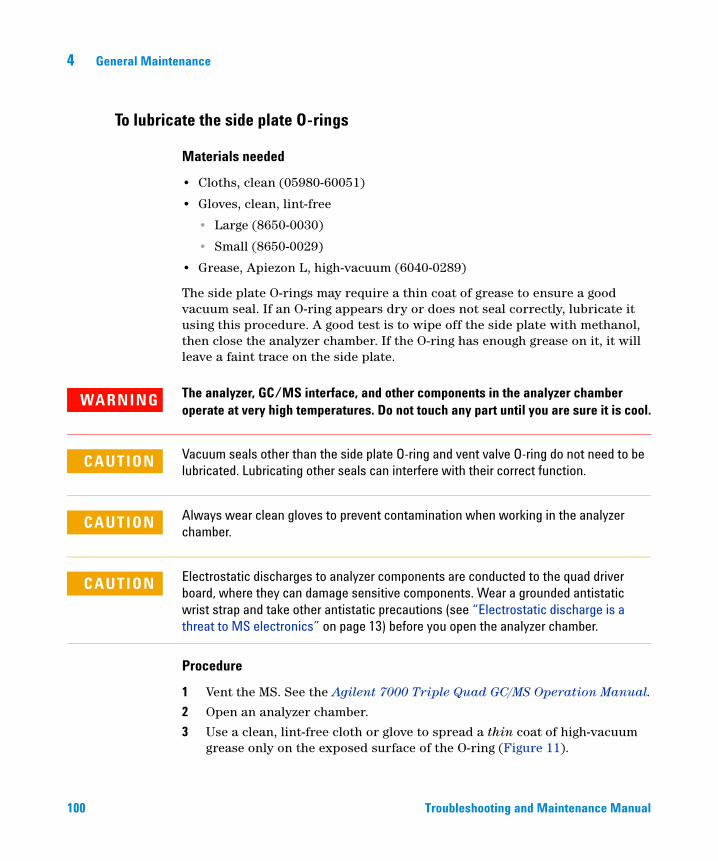
4 General Maintenance
To lubricate the side plate O-rings
100
Materials needed
• Cloths, clean (05980-60051)
• Gloves, clean, lint-free
• Large (8650-0030)
• Small (8650-0029)
• Grease, Apiezon L, high-vacuum (6040-0289)
The side plate O-rings may require a thin coat of grease to ensure a good vacuum seal. If an O-ring appears dry or does not seal correctly, lubricate it using this procedure. A good test is to wipe off the side plate with methanol, then close the analyzer chamber. If the O-ring has enough grease on it, it will leave a faint trace on the side plate.
The analyzer, GC/MS interface, and other components in the analyzer chamber
WARNINGoperate at very high temperatures. Do not touch any part until you are sure it is cool.CAUTION Vacuum seals other than the side plate O-ring and vent valve O-ring do not need to be lubricated. Lubricating other seals can interfere with their correct function.
CAUTION Always wear clean gloves to prevent contamination when working in the analyzer chamber.
CAUTION Electrostatic discharges to analyzer components are conducted to the quad driver board, where they can damage sensitive components. Wear a grounded antistatic wrist strap and take other antistatic precautions (see “Electrostatic discharge is a threat to MS electronics” on page 13) before you open the analyzer chamber.
Procedure
1 Vent the MS. See the Agilent 7000 Triple Quad GC/MS Operation Manual.
2 Open an analyzer chamber.
3 Use a clean, lint-free cloth or glove to spread a thin coat of high-vacuum grease only on the exposed surface of the O-ring (Figure 11).
Troubleshooting and Maintenance Manual
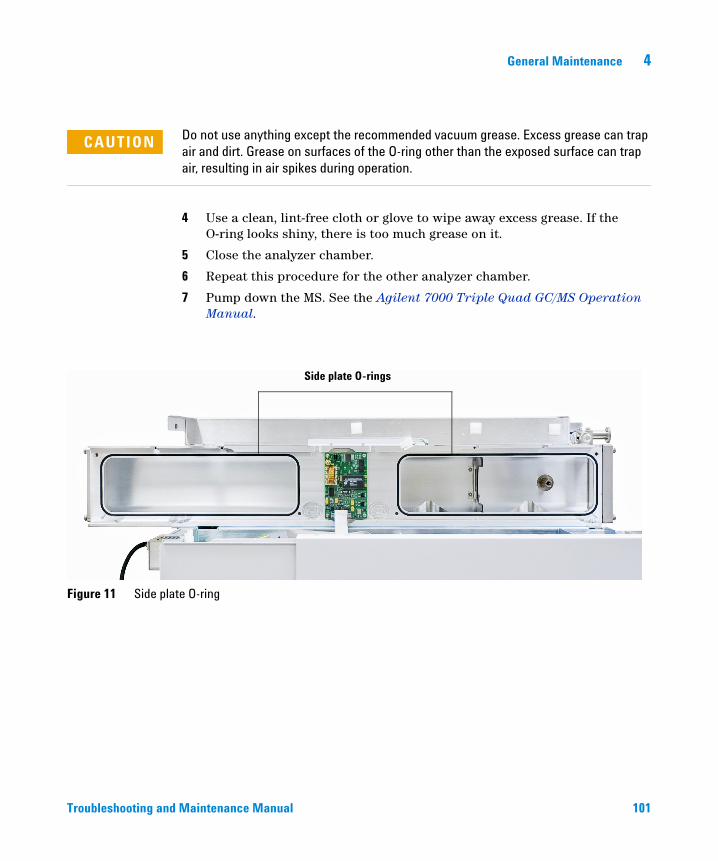
General Maintenance 4
Troubleshooting and
CAUTION Do not use anything except the recommended vacuum grease. Excess grease can trap air and dirt. Grease on surfaces of the O-ring other than the exposed surface can trap air, resulting in air spikes during operation.
4 Use a clean, lint-free cloth or glove to wipe away excess grease. If the O-ring looks shiny, there is too much grease on it.
5 Close the analyzer chamber.
6 Repeat this procedure for the other analyzer chamber.
7 Pump down the MS. See the Agilent 7000 Triple Quad GC/MS Operation Manual.
Figure 11 Side plate O-ring
Side plate O-rings
Maintenance Manual 101
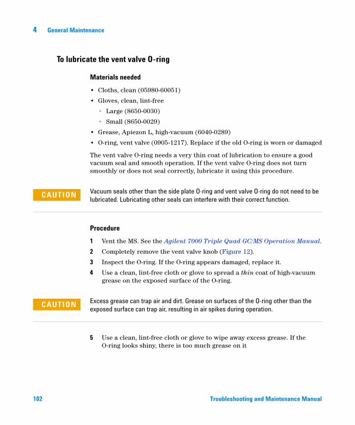
4 General Maintenance
To lubricate the vent valve O-ring
102
Materials needed
• Cloths, clean (05980-60051)
• Gloves, clean, lint-free
• Large (8650-0030)
• Small (8650-0029)
• Grease, Apiezon L, high-vacuum (6040-0289)
• O-ring, vent valve (0905-1217). Replace if the old O-ring is worn or damaged
The vent valve O-ring needs a very thin coat of lubrication to ensure a good vacuum seal and smooth operation. If the vent valve O-ring does not turn smoothly or does not seal correctly, lubricate it using this procedure.
CAUTION Vacuum seals other than the side plate O-ring and vent valve O-ring do not need to be lubricated. Lubricating other seals can interfere with their correct function.
Procedure
1 Vent the MS. See the Agilent 7000 Triple Quad GC/MS Operation Manual.
2 Completely remove the vent valve knob (Figure 12).
3 Inspect the O-ring. If the O-ring appears damaged, replace it.
4 Use a clean, lint-free cloth or glove to spread a thin coat of high-vacuum grease on the exposed surface of the O-ring.
CAUTION Excess grease can trap air and dirt. Grease on surfaces of the O-ring other than the exposed surface can trap air, resulting in air spikes during operation.
5 Use a clean, lint-free cloth or glove to wipe away excess grease. If the O-ring looks shiny, there is too much grease on it
Troubleshooting and Maintenance Manual
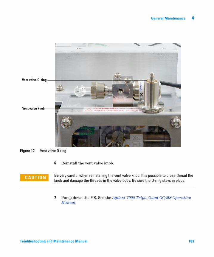
General Maintenance 4
Troubleshooting and
Figure 12 Vent valve O-ring
Vent valve knob
Vent valve O-ring
6 Reinstall the vent valve knob.
Be very careful when reinstalling the vent valve knob. It is possible to cross-thread the
CAUTIONknob and damage the threads in the valve body. Be sure the O-ring stays in place.7 Pump down the MS. See the Agilent 7000 Triple Quad GC/MS Operation Manual.
Maintenance Manual 103
4 General Maintenance
Maintaining the Analyzers and Collision Cell
Scheduling
104
None of the analyzer components requires periodic maintenance. Some tasks, however, must be performed when MS behavior indicates they are necessary. These tasks include:
• Cleaning the ion source
• Replacing filaments
• Replacing the electron multiplier horn
See Chapter 2, “General Troubleshooting” on page 25 for information about symptoms that indicate the need for analyzer maintenance.
Precautions
Cleanliness
Keep components clean during analyzer maintenance. Analyzer maintenance involves opening the analyzer chamber and removing parts from the analyzer. During analyzer maintenance procedures, take care to avoid contaminating the analyzer or the interior of the analyzer chamber.
Wear clean gloves during all analyzer maintenance procedures. After cleaning, parts must be thoroughly baked out before they are reinstalled and should be placed only on clean, lint-free cloths.
CAUTION If not done correctly, analyzer maintenance can introduce contaminants into the MS.
WARNING The analyzers operate at high temperatures. Do not touch any part until you are sure it is cool.
Troubleshooting and Maintenance Manual
General Maintenance 4
Troubleshooting and
Some parts can be damaged by electrostatic discharge
The wires, contacts, and cables connected to the analyzer components can carry electrostatic discharges (ESD) to the electronics boards to which they are connected. This is especially true of the mass filter (quadrupole) contact wires, which can conduct ESD to sensitive components on the quadrupole board. ESD damage may not cause immediate failure but will gradually degrade performance and stability. See “Electrostatic discharge” on page 79 for more information.
CAUTION Electrostatic discharges to analyzer components are conducted to the quadrupole board where they can damage sensitive components. Wear a grounded antistatic wrist strap (see “Electrostatic discharge” on page 79) and take other antistatic precautions before you open the analyzer chambers.
Some analyzer parts should not be disturbed
The mass filters (quadrupoles) require no periodic maintenance. In general, a mass filter should never be disturbed. In the event of extreme contamination, it can be cleaned, but such cleaning should only be done by a trained Agilent Technologies service representative. The HED insulator must never be touched.
More information is available
CAUTION Incorrect handling or cleaning of the mass filter can damage it and have a serious, negative effect on instrument performance. Do not touch the HED insulator.
See the Agilent 7000 Triple Quad GC/MS Operating Manual for information on removing, disassembling, cleaning, assembling, and installation of the ion source. This chapter contains procedures for removing and installing the heaters and sensors for the ion source and the analyzers.
If you need more information about the locations or functions of analyzer components, refer to Chapter 7, “Analyzers and Collision Cell” on page 135.
Maintenance Manual 105
4 General Maintenance
To remove/reinstall the heater/sensor assembly of the ion source
106
Materials needed
• Gloves, clean, lint-free
• Large (8650-0030)
• Small (8650-0029)
• Hex ball driver, 1.5 mm (8710-1570)
• Hex ball driver, 2.0 mm (8710-1804)
• Hex nut driver, 5.5 mm (8710-1220)
Removal
The analyzer, GC/MS interface, and other components in the analyzer chamber
WARNINGoperate at very high temperatures. Do not touch any part until you are sure it is cool.CAUTION Always wear clean gloves to prevent contamination when working in the analyzer chamber.
CAUTION Make sure you use an antistatic wrist strap and take other antistatic precautions before touching analyzer components.
1 Vent the MS. See the Agilent 7000 Triple Quad GC/MS Operation Manual.
2 Open the front analyzer chamber. See the Agilent 7000 Triple Quad GC/MS Operation Manual.
3 Remove the ion source. See “To remove the EI ion source” in the Agilent 7000 Triple Quad GC/MS Operation Manual.
4 Remove the filaments.
Troubleshooting and Maintenance Manual
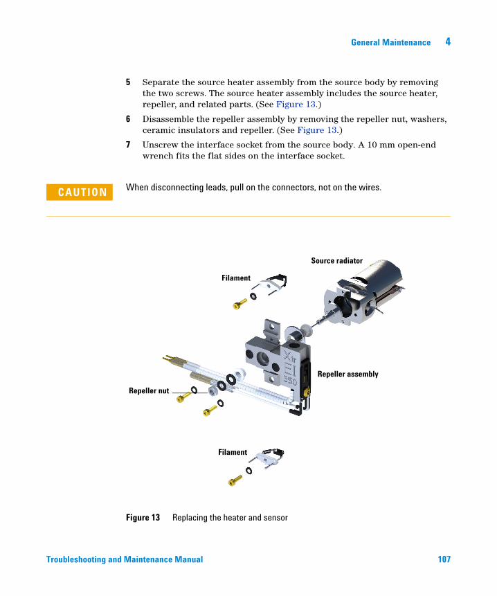
General Maintenance 4
Troubleshooting and
5 Separate the source heater assembly from the source body by removing the two screws. The source heater assembly includes the source heater, repeller, and related parts. (See Figure 13.)
6 Disassemble the repeller assembly by removing the repeller nut, washers, ceramic insulators and repeller. (See Figure 13.)
7 Unscrew the interface socket from the source body. A 10 mm open-end wrench fits the flat sides on the interface socket.
CAUTION When disconnecting leads, pull on the connectors, not on the wires.
Figure 13 Replacing the heater and sensor
Filament
Filament
Repeller assembly
Repeller nut
Source radiator
Maintenance Manual 107
108
4 General Maintenance
Reinstallation
1 Unpack the new source heater assembly (G3170-60177). The heater, temperature sensor, and heater block are already assembled.
CAUTION Always wear clean gloves to prevent contamination when working in the analyzer chamber.
2 Reinstall the repeller, repeller insulators, washer, and repeller nut (Figure 13). The resulting assembly is called the repeller assembly.
CAUTION Do not overtighten the repeller nut or the ceramic repeller insulators will break when the source heats up. The nut should only be finger-tight.
3 Connect the repeller assembly to the source body with the two screws and washers.
4 Reinstall the filaments.
WARNING The analyzers, GC/MS interface, and other components in the analyzer chamber operate at very high temperatures. Do not touch any part until you are sure it is cool.
Make sure you use an antistatic wrist strap and take other antistatic precautions
CAUTIONbefore touching analyzer components.5 Reinstall the ion source in the analyzer chamber.
6 Reconnect the wires from the feedthrough board to the ion source.
7 Reconnect the heater and temperature sensor wires to the feedthrough board.
8 Close the analyzer chamber.
9 Pump down the MS. See the Agilent 7000 Triple Quad GC/MS Operation Manual.
Troubleshooting and Maintenance Manual
General Maintenance 4
Maintaining the Electronics
Scheduled maintenance
Troubleshooting and
None of the electronic components of the MS needs to be replaced on a regular schedule. None of the electronic components in the MS needs to be adjusted or calibrated on a regular schedule. Avoid unnecessary handling of the MS electronics.
Electronic components
The primary fuses can be replaced by the operator. All other maintenance of the electronics should be performed by your Agilent Technologies service representative.
Electrostatic precautions
WARNING Improper use of these procedures could create a serious safety hazard. Improper use of these procedures could also result in serious damage to, or incorrect operation of, the MS.
WARNING Vent the MS and disconnect its power cord before performing any of these procedures except adjusting the RF coils.
All of the printed circuit boards in the MS contain components that can be damaged by electrostatic discharge (ESD). Do not handle or touch these boards unless absolutely necessary. In addition, wires, contacts, and cables can conduct ESD to the printed circuit boards to which they are connected. This is especially true of the mass filter (quadrupole) contact wires, which can carry ESD to sensitive components on the quadrupole board. ESD damage may not cause immediate failure but it will gradually degrade the performance and stability of your MS.
When you work on or near printed circuit boards, or when you work on components with wires, contacts, or cables connected to printed circuit boards, always use a grounded antistatic wrist strap and take other antistatic precautions. The wrist strap should be connected to a known good earth
Maintenance Manual 109
110
4 General Maintenance
ground. If that is not possible, it should be connected to a conductive (metal) part of the assembly being worked on, but not to electronic components, exposed wires or traces, or pins on connectors.
Take extra precautions, such as a grounded antistatic mat, if you must work on components or assemblies that have been removed from the MS. This includes the analyzer.
More information is available
CAUTION In order to be effective, an antistatic wrist strap must fit snugly (not tight). A loose strap provides little or no protection.
CAUTION Antistatic precautions are not 100% effective. Handle electronic circuit boards as little as possible and then only by the edges. Never touch the components, exposed traces, or pins on connectors and cables.
If you need more information about the functions of electronic components, refer to Chapter 8, “Electronics” on page 155.
Troubleshooting and Maintenance Manual
General Maintenance 4
To replace the primary fuses
Troubleshooting and
Materials needed
• Fuse, 8 A, time-delay slow blow, (2110-0969) – 2 required
• Fuse, 12.5 A, time-delay slow blow, (2110-1398) – 2 required
• Screwdriver, flat-blade (8730-0002)
The most likely cause of failure of the primary fuses is a problem with the foreline pump. If the primary fuses in your MS fail, check the foreline pump.
Procedure
1 Vent the MS (See the Agilent 7000 Triple Quad GC/MS Operation Manual) and unplug the power cord from the electrical outlet.
If one of the primary fuses has failed, the MS will already be off, but for safety you should switch off the MS and unplug the power cord. It is not necessary to allow air into the analyzer chamber.
WARNING Never replace the primary fuses while the MS is connected to a power source.
WARNING If you are using hydrogen as a GC carrier gas, a power failure may allow it to accumulate in the analyzer chamber. In that case, further precautions are required. See “Hydrogen Safety” .
2 The fuse holders are on the back panel. Turn one of the fuse holders counterclockwise until it pops out. The fuse holders are spring loaded.
3 Examine the fuse. If it is blown, remove the old fuse from the fuse holder.
4 Install a new fuse in the fuse holder. Each holder is marked with the correct fuse value.
5 Reinstall the fuse holder.
6 Repeat for the other three fuses.
Maintenance Manual 111
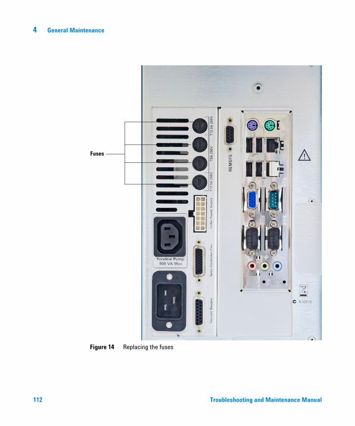
112
4 General Maintenance
Figure 14 Replacing the fuses
Fuses
Troubleshooting and Maintenance Manual

General Maintenance 4
Troubleshooting and
Maintenance Manual 113
114
4 General Maintenance
Troubleshooting and Maintenance Manual
Agilent 7000 Series Triple Quadrupole GC/MS Troubleshooting and Maintenance Manual
5CI Maintenance
To Minimize Foreline Pump Damage from Ammonia 116
To Replace the Methane/Isobutane Gas Purifier 117
To Clean the Reagent Gas Supply Lines 118
To Refill the CI Calibrant Vial 119
This chapter describes maintenance procedures and requirements that are unique to a 7000 Triple Quad GC/MS equipped with the Chemical Ionization hardware.
115Agilent Technologies
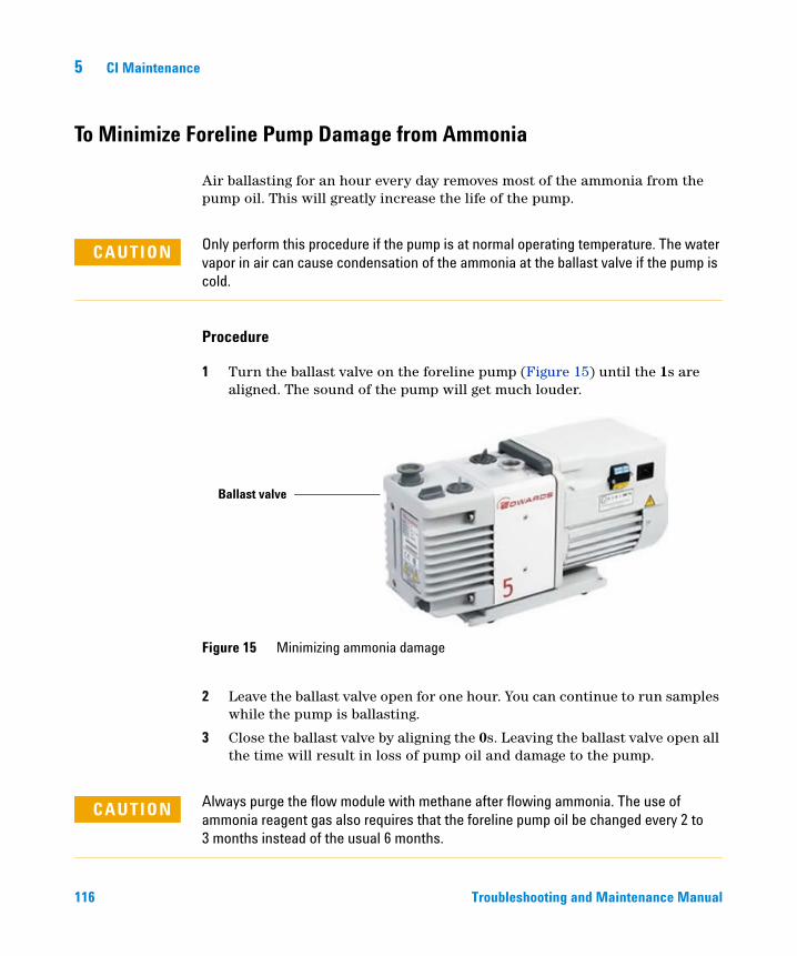
5 CI Maintenance
To Minimize Foreline Pump Damage from Ammonia
116
Air ballasting for an hour every day removes most of the ammonia from the pump oil. This will greatly increase the life of the pump.
CAUTION Only perform this procedure if the pump is at normal operating temperature. The water vapor in air can cause condensation of the ammonia at the ballast valve if the pump is cold.
Procedure
1 Turn the ballast valve on the foreline pump (Figure 15) until the 1s are aligned. The sound of the pump will get much louder.
2 Leave the ballast valve open for one hour. You can continue to run samples while the pump is ballasting.
3 Close the ballast valve by aligning the 0s. Leaving the ballast valve open all the time will result in loss of pump oil and damage to the pump.
Figure 15 Minimizing ammonia damage
Ballast valve
Always purge the flow module with methane after flowing ammonia. The use of
CAUTIONammonia reagent gas also requires that the foreline pump oil be changed every 2 to 3 months instead of the usual 6 months.Troubleshooting and Maintenance Manual
CI Maintenance 5
To Replace the Methane/Isobutane Gas Purifier
Troubleshooting and
Materials needed
• Methane/Isobutane gas purifier (G1999-80410)
• Front ferrule for 1/8-inch tubing (5180-4110)
• Rear ferrule for 1/8-inch tubing (5180-4116)
• Tubing cutter (8710-1709)
The methane/isobutane gas purifier needs to be replaced after four tanks of reagent gas. This frequency may vary depending on purity of the gas and care taken in uncapping and installing the gas purifier. A large leak upstream from the gas purifier can quickly exhaust the reduced metal of the oxygen and moisture traps.
Procedure
1 To install the methane/isobutane gas purifier, follow the instructions on the label for installation and replacement intervals.
CAUTION Do not remove the caps until you are ready to install the gas purifier. Only remove the caps in the gas flow to prevent contamination by air.
WARNING Methane is flammable. Extinguish all flames in the area before turning on gas flow.
2 Disconnect the fittings on the old filter.
3 Remove the ferrules from the tubing at the outlet of the gas purifier. Using the tubing cutter, cut off the end of the tubing with the ferrules.
4 Install the new filter.
5 Purge the new filter.
6 Cap the old filter and prepare it to be sent for regeneration. See the instructions on the label.
Maintenance Manual 117
5 CI Maintenance
To Clean the Reagent Gas Supply Lines
118
Materials needed
• Clean, dry nitrogen
• Heat gun
• Tubing cutter (8710-1709)
Procedure
If the reagent gas lines become contaminated, they can be cleaned.
1 Disconnect the reagent gas tubing from the gas supply, the gas purifier, and the MS.
2 Cap the gas purifier following the instructions on the label.
3 Connect one end of the tubing to a supply of clean, dry nitrogen and turn on gas flow.
4 Use the heat gun to warm the tubing, starting at the supply end and working your way to the free end.
5 Repeat for any other pieces of tubing that need to be cleaned.
6 Reconnect the tubing to the gas supply, gas purifier, and MS. Follow the instructions on the gas purifier label.
WARNING Do not heat the gas tubing when reagent gas is flowing.
CAUTION Do not put liquids into the tubing. Do not heat the tubing when it is connected to the MS.
Troubleshooting and Maintenance Manual
CI Maintenance 5
To Refill the CI Calibrant Vial
Troubleshooting and
Materials needed
• PFDTD calibrant (8500-8510)
Procedure
1 Set the reagent gas flow to Gas Off.
2 Vent the MS.
3 Remove the capillary column from the GC/MS interface.
4 Pull the MS away from the GC to expose the calibration vial and valve. See page 86.
5 Loosen the collar holding the calibration vial in place. Do not remove the collar.
6 Remove the calibrant vial. See Figure 16.
Do not rinse the vial with any solvents. Never expose the inside of the vial to
CAUTIONchlorinated solvents or isopropyl alcohol or water — this will result in severe loss of CI sensitivity.7 Fill the vial no higher than the bottom of the internal tube with fresh PFDTD calibrant (8500-8510).
8 Replace the vial and tighten the collar.
9 Reposition the MS next to the GC. See page 86.
10 Reinstall the capillary column.
11 Pump down the MS.
12 In Instrument Control panel, select the MS Tune icon to display the GC-QQQ Tune dialog box. Select the Manual Tune tab then select the Ion Source tab to display the ion source parameters.
13 Turn off the Emission by clicking in the check box.
After removing a calibrant vial, you must purge the calibration valve. Failure to do so
CAUTIONwill result in damage to the filaments and the electron multiplier.14 Purge the calibration valve by clicking in the CI Cal Valve check box to open the calibration valve. Close the CI Cal Valve after 30 seconds.
Maintenance Manual 119
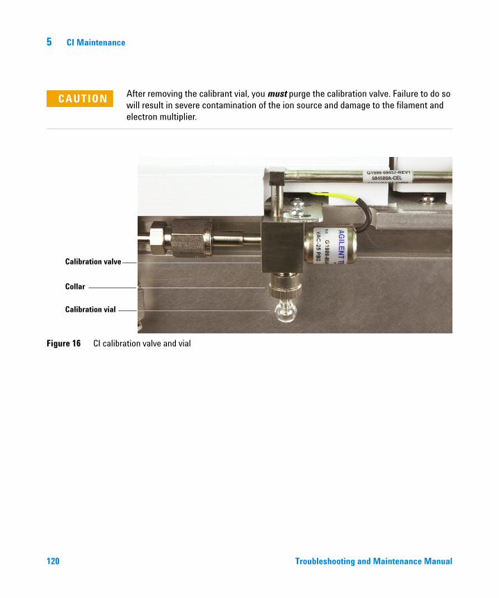
120
5 CI Maintenance
CAUTION After removing the calibrant vial, you must purge the calibration valve. Failure to do so will result in severe contamination of the ion source and damage to the filament and electron multiplier.
Figure 16 CI calibration valve and vial
Calibration valve
Calibration vial
Collar
Troubleshooting and Maintenance Manual
Agilent 7000 Series Triple Quadrupole GC/MS Troubleshooting and Maintenance Manual
6Vacuum System
Overview 122
Vacuum System Components 123
Common Vacuum System Problems 124
Foreline Pump 125
Turbo Pump 127
Analyzer Chambers 127
Side Plates 128
Vacuum Seals 129
Foreline Gauge 131
Turbo Pump and Fan 132
Calibration Valve and Vent Valve 133
This chapter describes components of the 7000 Triple Quad GC/MS vacuum system.
121Agilent Technologies
6 Vacuum System
Overview
122
The vacuum system creates the high vacuum (low pressure) required for the GC/MS to operate. Without the vacuum, the molecular mean free path would be very short and ions would collide with air molecules before they could reach the detector. Operation at high pressures also would damage analyzer components.
The 7000 Triple Quad GC/MS uses two vacuum pumps to obtain the vacuum levels needed. The foreline pump creates a low vacuum, then a high vacuum pump engages to create the vacuum needed for operation. The 7000 Triple Quad GC/MS uses one turbomolecular (turbo) pump.
Most of the vacuum system operation is automated. Operator interaction and monitoring is accomplished through the data system.
Troubleshooting and Maintenance Manual
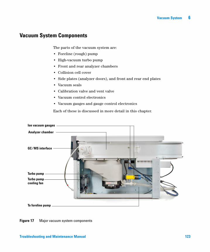
Vacuum System 6
Vacuum System Components
Troubleshooting and
The parts of the vacuum system are:
• Foreline (rough) pump
• High-vacuum turbo pump
• Front and rear analyzer chambers
• Collision cell cover
• Side plates (analyzer doors), and front and rear end plates
• Vacuum seals
• Calibration valve and vent valve
• Vacuum control electronics
• Vacuum gauges and gauge control electronics
Each of these is discussed in more detail in this chapter.
Figure 17 Major vacuum system components
To foreline pump
Turbo pump
Turbo pump
Analyzer chamber
GC/MS interface
Ion vacuum gauges
cooling fan
Maintenance Manual 123
6 Vacuum System
Common Vacuum System Problems
Air leak symptoms
124
The most common problems associated with any vacuum system are air leaks. Symptoms of air leaks include:
• Loud gurgling noise from the foreline pump (very large leak)
• Inability of the turbo pump to reach 95% speed
• Higher than normal high-vacuum gauge controller readings
The 7000 Triple Quad will not pump down successfully unless you press on the side boards (analyzer doors) when you turn on the MS power. Continue to press until the sound from the foreline pump becomes quieter.
Pumpdown failure shutdown
The system will shut down both the high-vacuum and the foreline pump if the system fails to pump down correctly. It takes approximately 10 minutes for the foreline pump to achieve 300 mTorr, which then starts the turbo pump. If the turbo pump speed is below 80% after an additional 10 minutes, the system shuts down.
This is usually because of a large air leak: either the side plates have not sealed correctly or the vent valve is still open. We suggest this pumpdown sequence:
1 Leave the vent valve partially open.
2 Start the pumpdown while holding the side plates closed.
3 When you hear a hissing sound, release the side plates and close the vent valve.
To restart the MS, find and correct the air leak, then switch the power off and on. Be sure to press on the side plates when turning on the MS power to ensure good seals.
Troubleshooting and Maintenance Manual
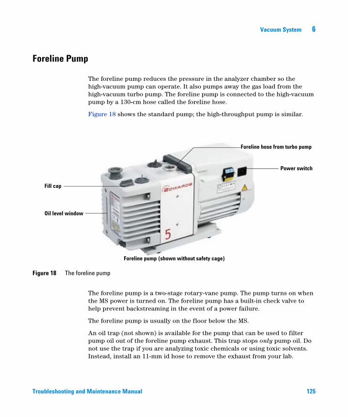
Vacuum System 6
Foreline Pump
Troubleshooting and
The foreline pump reduces the pressure in the analyzer chamber so the high-vacuum pump can operate. It also pumps away the gas load from the high-vacuum turbo pump. The foreline pump is connected to the high-vacuum pump by a 130-cm hose called the foreline hose.
Figure 18 shows the standard pump; the high-throughput pump is similar.
Figure 18 The foreline pump
Fill cap
Power switch
Oil level window
Foreline pump (shown without safety cage)
Foreline hose from turbo pump
The foreline pump is a two-stage rotary-vane pump. The pump turns on when the MS power is turned on. The foreline pump has a built-in check valve to help prevent backstreaming in the event of a power failure.
The foreline pump is usually on the floor below the MS.
An oil trap (not shown) is available for the pump that can be used to filter pump oil out of the foreline pump exhaust. This trap stops only pump oil. Do not use the trap if you are analyzing toxic chemicals or using toxic solvents. Instead, install an 11-mm id hose to remove the exhaust from your lab.
Maintenance Manual 125
126
6 Vacuum System
WARNING The oil trap supplied with the foreline pump stops only foreline pump oil. It does not trap or filter out toxic chemicals. If you are using toxic solvents or analyzing toxic chemicals, remove the oil trap. do not use the trap if you are using a CI MS. Install a hose to take the foreline pump exhaust outside or to a fume hood.
CAUTION Do not place the foreline pump near any equipment that is sensitive to vibration.
CAUTION The ballast control knob controls the amount of air allowed into the pump. Keep the ballast control closed (fully clockwise) at all times, except when ballasting the pump.
A window (sight glass) in the front of the foreline pump shows the level of the foreline pump oil. There are two marks next to the window. The level of the pump oil should never be above the upper mark or below the lower mark. If the level of pump oil is near the lower mark, add foreline pump oil.
The oil pan under the foreline pump can be a fire hazard
Oily rags, paper towels, and similar absorbents in the oil pan could ignite and damage the pump and other parts of the MS.
Combustible materials (or flammable/nonflammable wicking material) placed
WARNINGunder, over, or around the foreline (roughing) pump constitutes a fire hazard. Keep the pan clean, but do not leave absorbent material such as paper towels in it.Troubleshooting and Maintenance Manual
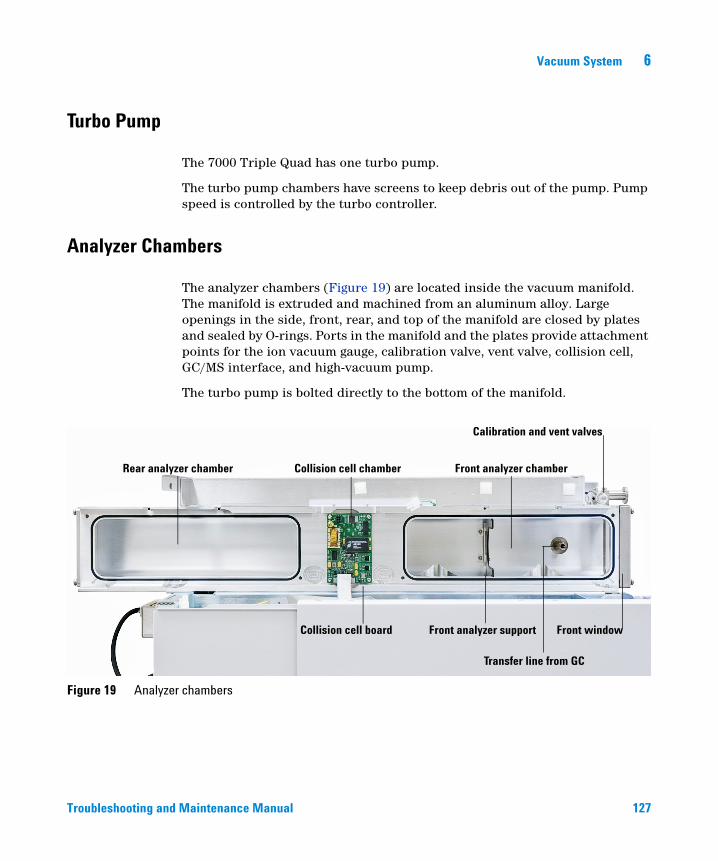
Vacuum System 6
Turbo Pump
Troubleshooting and
The 7000 Triple Quad has one turbo pump.
The turbo pump chambers have screens to keep debris out of the pump. Pump speed is controlled by the turbo controller.
Analyzer Chambers
The analyzer chambers (Figure 19) are located inside the vacuum manifold. The manifold is extruded and machined from an aluminum alloy. Large openings in the side, front, rear, and top of the manifold are closed by plates and sealed by O-rings. Ports in the manifold and the plates provide attachment points for the ion vacuum gauge, calibration valve, vent valve, collision cell, GC/MS interface, and high-vacuum pump.
The turbo pump is bolted directly to the bottom of the manifold.
Figure 19 Analyzer chambers
Front analyzer chamberRear analyzer chamber Collision cell chamber
Front window
Calibration and vent valves
Front analyzer supportCollision cell board
Transfer line from GC
Maintenance Manual 127
6 Vacuum System
Side Plates
128
The side plates cover the large openings in the side of the manifold. They are attached to the manifold with hinges. The analyzer assemblies are attached to the side plates inside the analyzer chambers. The hinges allow the side plates to swing away from the manifold for easy access to the analyzers.
The front side plate carries the front quadrupole driver and the filament drive. The rear side plate carries the rear quadrupole driver and the detector board.
Several electrical feedthroughs are built into the side plates. Wires connect the feedthroughs to analyzer components.
Thumbscrews are located at each end of the side plates. We recommend that the thumbscrews be loosely tightened
CAUTION Fasten both side plate thumbscrews for shipping or storage only. For normal operation, both thumbscrews should be loose. For operation with hydrogen carrier gas, or with flammable or explosive reagent gases, the top thumbscrews on the analyzer side plates should be fastened just finger-tight. Overtightening will warp the side plate and cause air leaks. Do not use a tool to tighten the side plate thumbscrews.
CAUTION When you turn on the power to pump down the MS, be sure to press on the side boards to ensure good seals.
Troubleshooting and Maintenance Manual
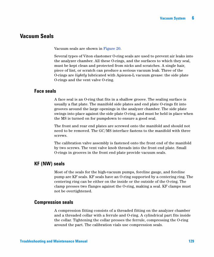
Vacuum System 6
Vacuum Seals
Troubleshooting and
Vacuum seals are shown in Figure 20.
Several types of Viton elastomer O-ring seals are used to prevent air leaks into the analyzer chamber. All these O-rings, and the surfaces to which they seal, must be kept clean and protected from nicks and scratches. A single hair, piece of lint, or scratch can produce a serious vacuum leak. Three of the O-rings are lightly lubricated with Apiezon-L vacuum grease: the side plate O-rings and the vent valve O-ring.
Face seals
A face seal is an O-ring that fits in a shallow groove. The sealing surface is usually a flat plate. The manifold side plates and end plate O-rings fit into grooves around the large openings in the analyzer chamber. The side plate swings into place against the side plate O-ring, and must be held in place when the MS is turned on for pumpdown to ensure a good seal.
The front and rear end plates are screwed onto the manifold and should not need to be removed. The GC/MS interface fastens to the manifold with three screws.
The calibration valve assembly is fastened onto the front end of the manifold by two screws. The vent valve knob threads into the front end plate. Small O-rings in grooves in the front end plate provide vacuum seals.
KF (NW) seals
Most of the seals for the high-vacuum pumps, foreline gauge, and foreline pump are KF seals. KF seals have an O-ring supported by a centering ring. The centering ring can be either on the inside or the outside of the O-ring. The clamp presses two flanges against the O-ring, making a seal. KF clamps must not be overtightened.
Compression seals
A compression fitting consists of a threaded fitting on the analyzer chamber and a threaded collar with a ferrule and O-ring. A cylindrical part fits inside the collar. Tightening the collar presses the ferrule, compressing the O-ring around the part. The calibration vials use compression seals.
Maintenance Manual 129
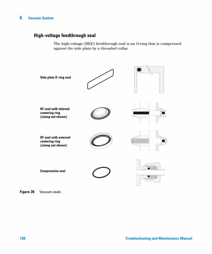
6 Vacuum System
High-voltage feedthrough seal
130
The high-voltage (HED) feedthrough seal is an O-ring that is compressed against the side plate by a threaded collar.
Figure 20 Vacuum seals
Side plate O-ring seal
KF seal with internalcentering ring
KF seal with externalcentering ring
Compression seal
(clamp not shown)
(clamp not shown)
Troubleshooting and Maintenance Manual
Vacuum System 6
Foreline Gauge
Troubleshooting and
The foreline gauge monitors the pressure (vacuum) at the exit of the turbo pump. The primary function of the foreline gauge is pump control. When the foreline pump has reduced the pressure in the analyzer chamber to below 10 Torr, the turbo pump is automatically switched on.
Maintenance Manual 131
6 Vacuum System
Turbo Pump and Fan
132
The turbo pump is bolted directly to the bottom of the manifold.
The main inlet to the turbo pump is under the front analyzer. A secondary inlet is near the ion source. The pump body is a central shaft or cylinder. Sets of small blades (airfoils) radiate from the central shaft. The shaft spins at up to 60,000 revolutions per minute (rpm).
Turbo pumps move gas by momentum transfer. The turbine blades are angled so that when they strike a gas molecule it is deflected downward. Each set of blades pushes the gas molecules further down toward the pump outlet.
The foreline pump is connected by a hose to the outlet of the turbo pump. It removes the gas molecules that reach the outlet.
A controller regulates current to the pump and monitors pump motor speed and temperature. A cooling fan is located between the turbo pump and the front panel of the MS. The fan draws air from outside the MS and blows it over the pump.
The turbo pump turns on automatically when the foreline pump has reduced the pressure below 10 Torr. The system allows the analyzer to be turned on when the turbo pump is greater than 80% speed, but the pump normally operates at 100% speed. Turbo pump MSs typically maintain an indicated pressure below 8 × 10⁻⁵ Torr for helium column flows up to 4 mL/minute.
The turbo pump spins up (starts) and spins down (stops) quickly. This simplifies pumpdown and venting. From initial power-on, the system can pump down to operating pressure in 5 to 10 minutes.
See Also
• To pump down the MS (See the Agilent 7000 Triple Quad GC/MS Operation Manual.)
• To vent the MS (See the Agilent 7000 Triple Quad GC/MS Operation Manual.)
Troubleshooting and Maintenance Manual
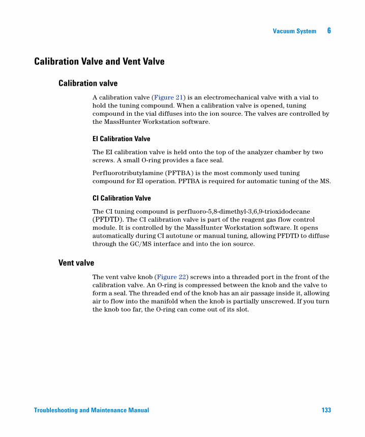
Vacuum System 6
Calibration Valve and Vent Valve
Calibration valve
Troubleshooting and
A calibration valve (Figure 21) is an electromechanical valve with a vial to hold the tuning compound. When a calibration valve is opened, tuning compound in the vial diffuses into the ion source. The valves are controlled by the MassHunter Workstation software.
EI Calibration Valve
The EI calibration valve is held onto the top of the analyzer chamber by two screws. A small O-ring provides a face seal.
Perfluorotributylamine (PFTBA) is the most commonly used tuning compound for EI operation. PFTBA is required for automatic tuning of the MS.
CI Calibration Valve
The CI tuning compound is perfluoro-5,8-dimethyl-3,6,9-trioxidodecane (PFDTD). The CI calibration valve is part of the reagent gas flow control module. It is controlled by the MassHunter Workstation software. It opens automatically during CI autotune or manual tuning, allowing PFDTD to diffuse through the GC/MS interface and into the ion source.
Vent valve
The vent valve knob (Figure 22) screws into a threaded port in the front of the calibration valve. An O-ring is compressed between the knob and the valve to form a seal. The threaded end of the knob has an air passage inside it, allowing air to flow into the manifold when the knob is partially unscrewed. If you turn the knob too far, the O-ring can come out of its slot.
Maintenance Manual 133
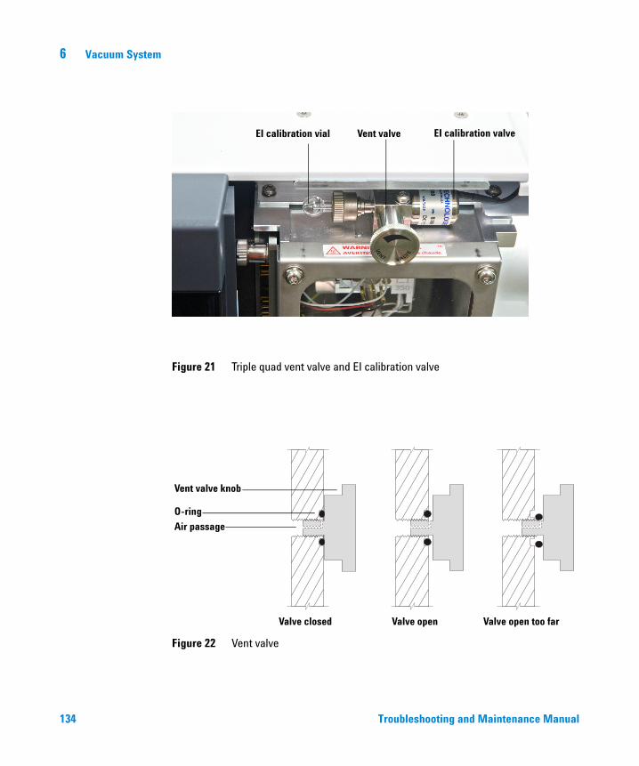
134
6 Vacuum System
Figure 21 Triple quad vent valve and EI calibration valve
Figure 22 Vent valve
EI calibration valveVent valveEI calibration vial
Vent valve knob
O-ring
Air passage
Valve closed Valve open Valve open too far
Trouble
shooting and Maintenance Manual
Agilent 7000 Series Triple Quadrupole GC/MSTroubleshooting and Maintenance Manual
7Analyzers and Collision Cell
Overview 136
EI Ion Source 138
CI Ion Source 143
Filaments 139
Other Source Elements 141
CI source exploded view 144
Post- and Pre-Filters 148
Collision Cell 149
Detector 150
Analyzer Heaters and Radiators 154
135Agilent Technologies
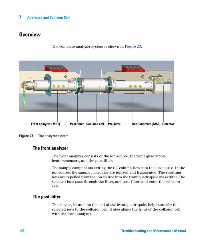
7 Analyzers and Collision Cell
Overview
136
The complete analyzer system is shown in Figure 23.
The front analyzer
Figure 23 The analyzer system
Front analyzer (MS1) Post-filter Collision cell Pre-filter Rear analyzer (MS2) Detector
The front analyzer consists of the ion source, the front quadrupole, heaters/sensors, and the post-filter.
The sample components exiting the GC column flow into the ion source. In the ion source, the sample molecules are ionized and fragmented. The resulting ions are repelled from the ion source into the front quadrupole mass filter. The selected ions pass through the filter, and post-filter, and enter the collision cell.
The post-filter
This device, located on the end of the front quadrupole, helps transfer the selected ions to the collision cell. It also aligns the front of the collision cell with the front analyzer.
Troubleshooting and Maintenance Manual
Analyzers and Collision Cell 7
The collision cell
Troubleshooting and
The precursor ions selected by the front quadrupole collide with a reaction gas, typically a nitrogen/helium mixture. This generates additional product ions.
The pre-filter
This device, located on the entrance of the rear analyzer, transfers the remaining precursor ions and the product ions generated in the collision cell to the rear analyzer. It also aligns the rear of the collision cell with the rear analyzer.
The rear analyzer
The rear analyzer consists of the rear quadrupole, the detector, and a heater/sensor assembly.
The ion stream now consists of the ions selected by the front analyzer and the ions formed by collision with the reaction gas. The rear analyzer separates these ions and passes them to the detector.
The detector
Ions that pass the rear analyzer strike a high-energy dynode, where they generate secondary electrons. These enter a multiplier and are collected to become the output signal.
Maintenance Manual 137
7 Analyzers and Collision Cell
EI Ion Source
138
The EI ion source (Figure 25) operates by electron impact ionization. The sample enters the ion source from the GC/MS interface. Electrons emitted by a filament enter the ionization chamber, guided by a magnetic field. The high-energy electrons interact with the sample molecules, ionizing and fragmenting them. The positive voltage on the repeller pushes the positive ions into the lens stack, where they pass through several electrostatic lenses. These lenses concentrate the ions into a tight beam, which is directed into the mass filter.
Ion source body
The ion source body (Figure 25) is a cylinder. It holds the other parts of the ion source, including the lens stack. With the repeller, it forms the ionization chamber. The ionization chamber is the space where the ions are formed. Slots in the source body help the vacuum system to pump away carrier gas and un-ionized sample molecules or fragments.
The CI ion source is similar in design, but critical dimensions are different. Do not interchange parts.
Troubleshooting and Maintenance Manual
Analyzers and Collision Cell 7
Filaments
Troubleshooting and
Two filaments (Figure 25 and Figure ) are located on opposite sides of the outside of the EI ion source. The active filament carries an adjustable AC emission current. The emission current heats the filament causing it to emit electrons which ionize the sample molecules. In addition, both filaments have an adjustable DC bias voltage. The bias voltage determines the energy on the electrons, usually –70 eV.
The CI ion source has only one filament of a different design from the EI filaments. A “dummy” filament provides connections for the Filament 2 wires.
The filament is shut off automatically if there is a general instrument shutdown. Three parameters affect the filaments: filament selection (Filament), filament emission (Emission) current, and electron energy (EIEnrgy).
Filament selection
The filament selection parameter (Filament) selects which filament in the ion source is active. In the CI source, it is always Filament 1.
Since filaments may have some variability, we advise running a tune for each filament and saving the tune accordingly.
Emission current
The filament emission current (Emission) is variable between 0 and –315 µA, but should be set to the software default for normal operation.
Electron energy
The electron energy (EIEnrgy) is the amount of energy on the ionizing electrons. It is determined by the bias voltage; –70 VDC bias on the filament causes emitted electrons to possess –70 eV (electron volts). This value is adjustable from –5 to –241 VDC, but for normal operation, set this parameter to 70.
Maintenance Manual 139
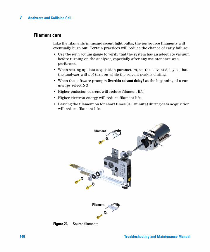
7 Analyzers and Collision Cell
Filament care
140
Like the filaments in incandescent light bulbs, the ion source filaments will eventually burn out. Certain practices will reduce the chance of early failure:
• Use the ion vacuum gauge to verify that the system has an adequate vacuum before turning on the analyzer, especially after any maintenance was performed.
• When setting up data acquisition parameters, set the solvent delay so that the analyzer will not turn on while the solvent peak is eluting.
• When the software prompts Override solvent delay? at the beginning of a run, always select NO.
• Higher emission current will reduce filament life.
• Higher electron energy will reduce filament life.
• Leaving the filament on for short times (< 1 minute) during data acquisition will reduce filament life.
Figure 24 Source filaments
Filament
Filament
Troubleshooting and Maintenance Manual
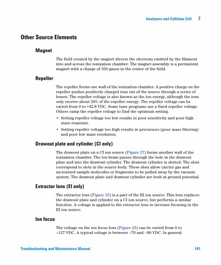
Analyzers and Collision Cell 7
Other Source Elements
Magnet
Troubleshooting and
The field created by the magnet directs the electrons emitted by the filament into and across the ionization chamber. The magnet assembly is a permanent magnet with a charge of 350 gauss in the center of the field.
Repeller
The repeller forms one wall of the ionization chamber. A positive charge on the repeller pushes positively charged ions out of the source through a series of lenses. The repeller voltage is also known as the ion energy, although the ions only receive about 20% of the repeller energy. The repeller voltage can be varied from 0 to +42.8 VDC. Some tune programs use a fixed repeller voltage. Others ramp the repeller voltage to find the optimum setting.
• Setting repeller voltage too low results in poor sensitivity and poor high mass response.
• Setting repeller voltage too high results in precursors (poor mass filtering) and poor low mass resolution.
Drawout plate and cylinder (CI only)
The drawout plate on a CI ion source (Figure 27) forms another wall of the ionization chamber. The ion beam passes through the hole in the drawout plate and into the drawout cylinder. The drawout cylinder is slotted. The slots correspond to slots in the source body. These slots allow carrier gas and un-ionized sample molecules or fragments to be pulled away by the vacuum system. The drawout plate and drawout cylinder are both at ground potential.
Extractor lens (EI only)
The extractor lens (Figure 25) is a part of the EI ion source. This lens replaces the drawout plate and cylinder on a CI ion source, but performs a similar function. A voltage is applied to the extractor lens to increase focusing in the EI ion source.
Ion focus
The voltage on the ion focus lens (Figure 25) can be varied from 0 to –127 VDC. A typical voltage is between –70 and –90 VDC. In general:
Maintenance Manual 141
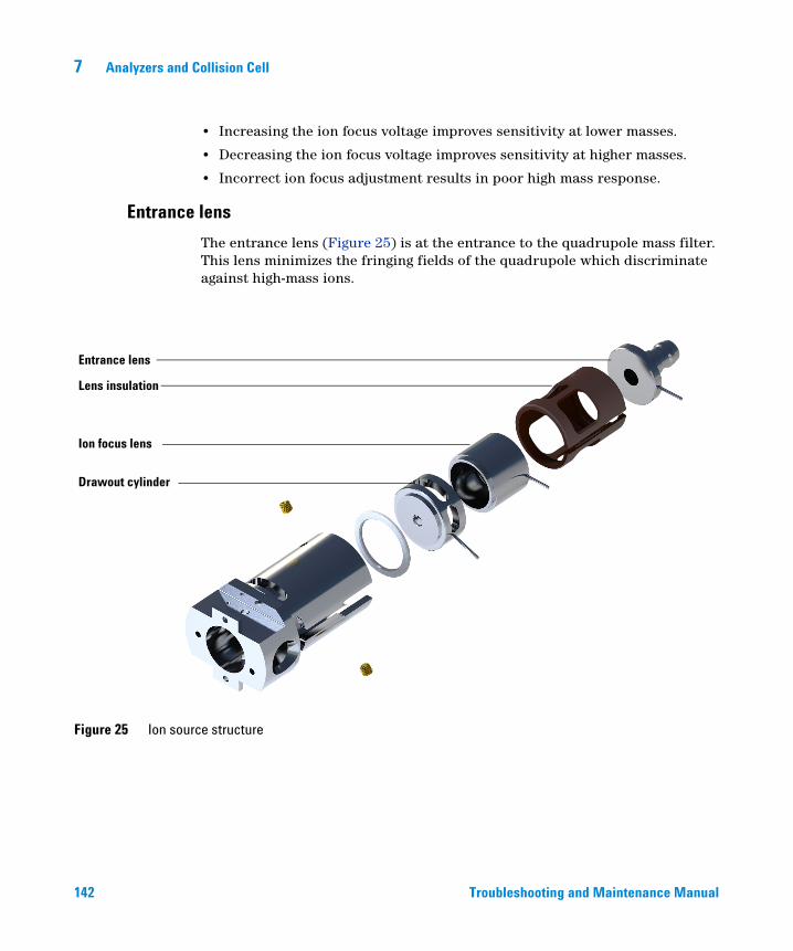
142
7 Analyzers and Collision Cell
• Increasing the ion focus voltage improves sensitivity at lower masses.
• Decreasing the ion focus voltage improves sensitivity at higher masses.
• Incorrect ion focus adjustment results in poor high mass response.
Entrance lens
The entrance lens (Figure 25) is at the entrance to the quadrupole mass filter. This lens minimizes the fringing fields of the quadrupole which discriminate against high-mass ions.
Figure 25 Ion source structure
Entrance lens
Drawout cylinder
Ion focus lens
Lens insulation
Troubleshooting and Maintenance Manual
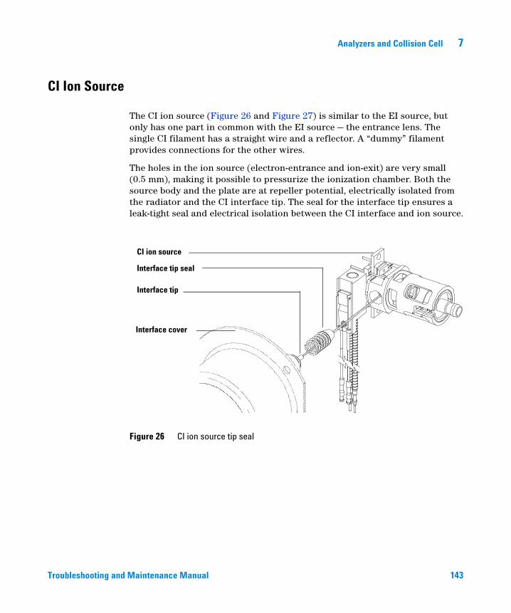
Analyzers and Collision Cell 7
CI Ion Source
Troubleshooting and
The CI ion source (Figure 26 and Figure 27) is similar to the EI source, but only has one part in common with the EI source — the entrance lens. The single CI filament has a straight wire and a reflector. A “dummy” filament provides connections for the other wires.
The holes in the ion source (electron-entrance and ion-exit) are very small (0.5 mm), making it possible to pressurize the ionization chamber. Both the source body and the plate are at repeller potential, electrically isolated from the radiator and the CI interface tip. The seal for the interface tip ensures a leak-tight seal and electrical isolation between the CI interface and ion source.
Figure 26 CI ion source tip seal
CI ion source
Interface tip seal
Interface tip
Interface cover
M
aintenance Manual 143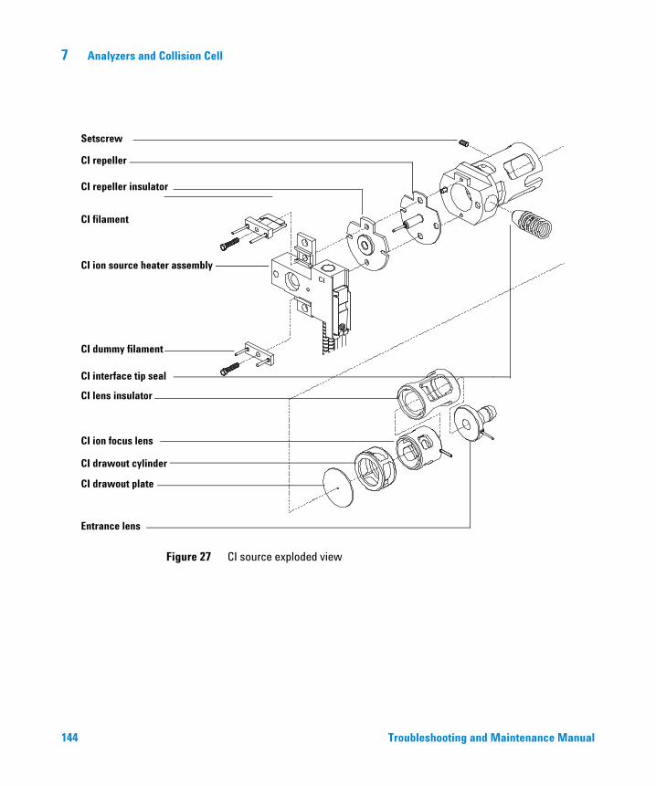
144
7 Analyzers and Collision Cell
Setscrew
CI repeller
CI repeller insulator
CI filament
CI ion source heater assembly
CI dummy filament
CI interface tip seal
CI lens insulator
CI ion focus lens
CI drawout cylinder
CI drawout plate
Entrance lens
Figure 27 CI source exploded view
Troubleshooting and Maintenance Manual
Analyzers and Collision Cell 7
Quadrupole Mass Filters
Troubleshooting and
The mass filters separate ions according to their mass-to-charge ratio (m/z). At a given time, only ions of a selected mass-to-charge ratio can pass through the filter to the detector. The mass filters in the MS are quadrupoles (Figure 28).
The quadrupole is a set of four fused-silica (quartz) rods coated with a thin layer of gold. The four hyperbolic surfaces create the complex electric fields necessary for mass selection. Opposing rods are connected; adjacent rods are electrically isolated. One pair has positive voltages applied, the other negative.
A combined direct current (DC) and radio frequency (RF) signal is applied to the two pairs of rods. The magnitude of the RF voltage determines the mass-to-charge ratio of the ions that pass through the mass filter and reach the detector. The ratio of DC-to-RF determines the resolution (widths of the mass peaks). There are several parameters that control the DC and RF voltages. All these parameters are set by Autotune, but also can be manually adjusted in the Edit Parameters window:
• Width gain
• Width offset
• DC polarity
• Mass axis gain
• Mass axis offset
Maintenance Manual 145
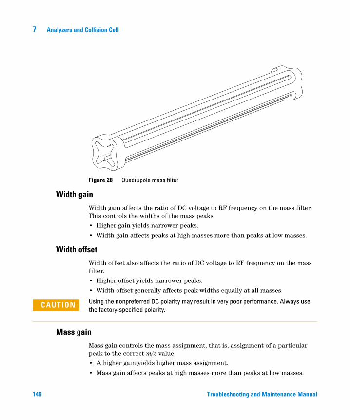
146
7 Analyzers and Collision Cell
Figure 28 Quadrupole mass filter
Width gain
Width gain affects the ratio of DC voltage to RF frequency on the mass filter. This controls the widths of the mass peaks.
• Higher gain yields narrower peaks.
• Width gain affects peaks at high masses more than peaks at low masses.
Width offset
Width offset also affects the ratio of DC voltage to RF frequency on the mass filter.
• Higher offset yields narrower peaks.
• Width offset generally affects peak widths equally at all masses.
Using the nonpreferred DC polarity may result in very poor performance. Always use
Mass gain
CAUTIONthe factory-specified polarity.
Mass gain controls the mass assignment, that is, assignment of a particular peak to the correct m/z value.
• A higher gain yields higher mass assignment.
• Mass gain affects peaks at high masses more than peaks at low masses.
Troubleshooting and Maintenance Manual
Analyzers and Collision Cell 7
Mass axis offset
Troubleshooting and
Mass offset also controls the mass assignment.
• A higher offset yields higher mass assignment.
• Mass offset generally affects peaks equally at all masses.
Quadrupole maintenance
The mass filter requires no periodic maintenance. It should not be removed from the radiator. If absolutely necessary (that is, if the only alternative is replacement), the quadrupole can be cleaned. Cleaning must be performed by Agilent Technologies service personnel.
CAUTION Never put the quadrupole in an ultrasonic cleaner.
Never change the physical orientation of the quadrupole mass filter.
The fused-quartz quadrupole is fragile and will break if dropped or handled roughly.
The material in the cusps of the quadrupole is very hygroscopic. If exposed to water, the quadrupole must be dried very slowly to prevent damage.
Maintenance Manual 147
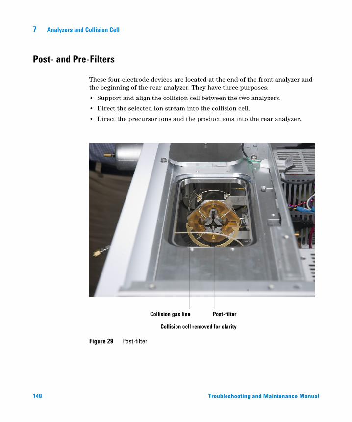
7 Analyzers and Collision Cell
Post- and Pre-Filters
148
These four-electrode devices are located at the end of the front analyzer and the beginning of the rear analyzer. They have three purposes:
• Support and align the collision cell between the two analyzers.
• Direct the selected ion stream into the collision cell.
• Direct the precursor ions and the product ions into the rear analyzer.
Figure 29 Post-filter
Post-filterCollision gas line
Collision cell removed for clarity
Troubleshooting and Maintenance Manual
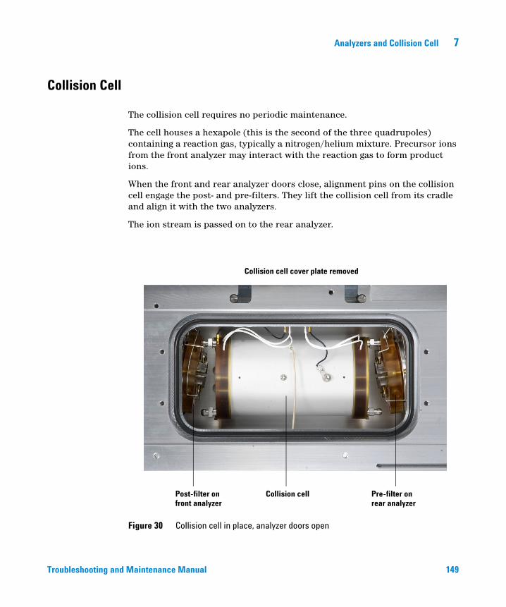
Analyzers and Collision Cell 7
Collision Cell
Troubleshooting and
The collision cell requires no periodic maintenance.
The cell houses a hexapole (this is the second of the three quadrupoles) containing a reaction gas, typically a nitrogen/helium mixture. Precursor ions from the front analyzer may interact with the reaction gas to form product ions.
When the front and rear analyzer doors close, alignment pins on the collision cell engage the post- and pre-filters. They lift the collision cell from its cradle and align it with the two analyzers.
The ion stream is passed on to the rear analyzer.
Figure 30 Collision cell in place, analyzer doors open
Collision cell cover plate removed
Post-filter onfront analyzer
Pre-filter onrear analyzer
Collision cell
Maintenance Manual 149
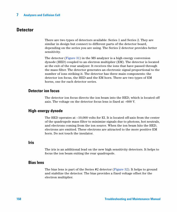
7 Analyzers and Collision Cell
Detector
150
There are two types of detectors available: Series 1 and Series 2. They are similar in design but connect to different parts of the detector board, depending on the series you are using. The Series 2 detector provides better sensitivity.
The detector (Figure 31) in the MS analyzer is a high energy conversion dynode (HED) coupled to an electron multiplier (EM). The detector is located at the exit of the rear analyzer. It receives the ions that have passed through the mass filter. The detector generates an electronic signal proportional to the number of ions striking it. The detector has three main components: the detector ion focus, the HED and the EM horn. There are two types of EM horns, one for each detector series.
Detector ion focus
The detector ion focus directs the ion beam into the HED, which is located off axis. The voltage on the detector focus lens is fixed at –600 V.
High-energy dynode
The HED operates at –10,000 volts for EI. It is located off-axis from the center of the quadrupole mass filter to minimize signals due to photons, hot neutrals, and electrons coming from the ion source. When the ion beam hits the HED, electrons are emitted. These electrons are attracted to the more positive EM horn. Do not touch the insulator.
Iris
The iris is an additional lead on the new high sensitivity detectors. It helps to focus the ion beam exiting the rear quadrupole.
Bias lens
The bias lens is part of the Series #2 detector (Figure 32). It helps to ground and stabilize the detector. The bias provides a fixed voltage offset for the electron multiplier.
Troubleshooting and Maintenance Manual
Analyzers and Collision Cell 7
EM horn
Troubleshooting and
There are two types of horns that can be used: Series 1 and Series 2. They are similar in design, but only fit in the detector that corresponds to its series. (Figure 31 and Figure 32). The EM horn carries a voltage of up to –3000 volts at its opening and 0 volts at the other end. The electrons emitted by the HED strike the EM horn and cascade through the horn, liberating more electrons as they go. At the far end of the horn, the current generated by the electrons is carried through a shielded cable outside the analyzer to the signal amplifier board.
The voltage applied to the EM horn determines the gain. The voltage is adjustable from 0 to –3000 VDC. Use the EM voltage found in autotune as a baseline for the EM voltage setting.
• To increase signal gain, increase the EM voltage.
• For concentrated samples where less signal gain is needed, decrease the EM voltage.
Maintenance Manual 151
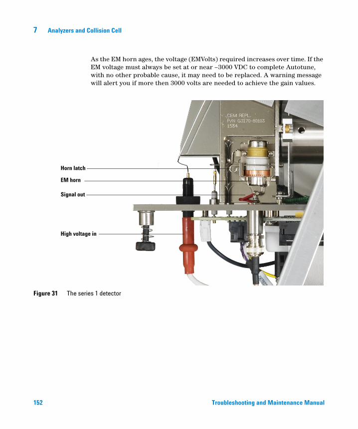
152
7 Analyzers and Collision Cell
As the EM horn ages, the voltage (EMVolts) required increases over time. If the EM voltage must always be set at or near –3000 VDC to complete Autotune, with no other probable cause, it may need to be replaced. A warning message will alert you if more then 3000 volts are needed to achieve the gain values.
Figure 31 The series 1 detector
High voltage in
EM horn
Horn latch
Signal out
Troubleshooting and Maintenance Manual
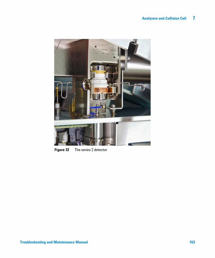
Analyzers and Collision Cell 7
Troubleshooting and
Figure 32 The series 2 detector
Maintenance Manual 153
7 Analyzers and Collision Cell
Analyzer Heaters and Radiators
154
The ion source and mass filter are housed in cylindrical aluminum tubes called radiators (Figure 33). The radiators control the distribution of heat in the analyzer. They also provide electrical shielding for analyzer components. The source heater and temperature sensor are mounted in the source heater block. The mass filter (quad) heaters and temperature sensors are mounted on the mass filter radiators. Analyzer temperatures can be set and monitored from the MassHunter Workstation software.
In selecting the temperatures to use, consider the following:
• Higher temperatures help keep the analyzer clean longer.
• Higher ion source temperatures result in more fragmentation and therefore lower high-mass sensitivity.
After pumpdown, it takes at least 2 hours for the analyzer to reach thermal equilibrium. Data acquired sooner may not be reproducible.
Recommended settings (for EI operation):
• Ion source 230 C• Quadrupoles (front and rear)150 C
Do not exceed 200 °C on the quadrupole or 350 °C on the ion source.
CAUTIONThe GC/MS interface, ion source, and front mass filter (quad) heated zones interact. The analyzer heaters may not be able to accurately control temperatures if the setpoint for one zone is much lower than that of an adjacent zone.
Troubleshooting and Maintenance Manual
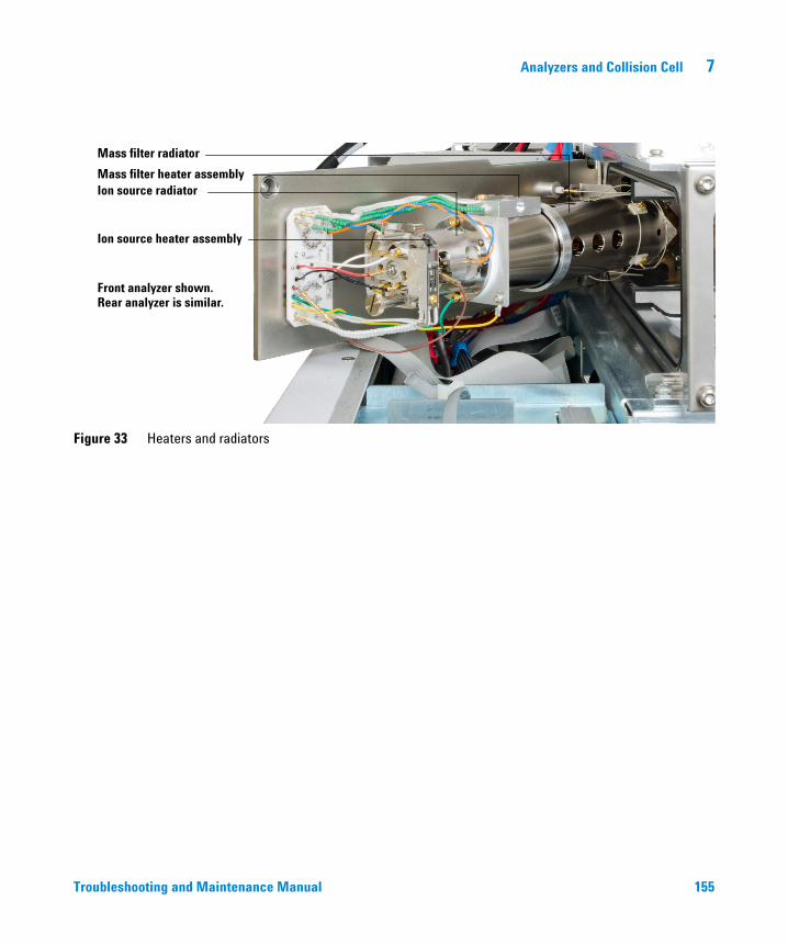
Analyzers and Collision Cell 7
Troubleshooting and
Figure 33 Heaters and radiators
Mass filter radiator
Mass filter heater assemblyIon source radiator
Ion source heater assembly
Front analyzer shown.Rear analyzer is similar.
Maintenance Manual 155

156
7 Analyzers and Collision Cell
Troubleshooting and Maintenance Manual
Agilent 7000 Series Triple Quadrupole GC/MS Troubleshooting and Maintenance Manual
8Electronics
Power Switch 156
Ion Source Board 157
Quadrupole Boards 158
Collision Cell Board 159
Detector Board 160
Electronics Module 161
Bus board 166
PLX card 166
LAN/MS Control Card (Smartcard 4) 166
Power Supplies 167
Back Panel Connectors 168
Interfacing to External Devices 170
The following assemblies make up the MS electronics:
Except for the Back panel and connectors, and Interfacing to external devices sections, most of this material is not essential for day-to-day operation of the GC/MS. It may be of interest to persons responsible for servicing the GC/MS.
Dangerous voltages are present under the safety covers. Do not remove safety
WARNINGcovers. Refer servicing to your Agilent Technologies service representative.155Agilent Technologies
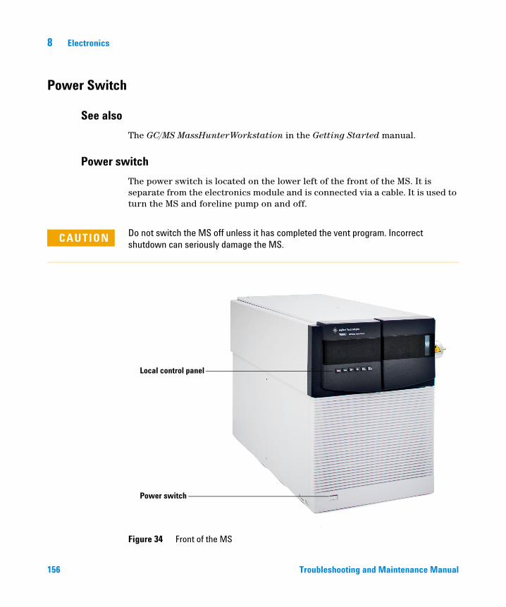
8 Electronics
Power Switch
See also
156
The GC/MS MassHunterWorkstation in the Getting Started manual.
Power switch
The power switch is located on the lower left of the front of the MS. It is separate from the electronics module and is connected via a cable. It is used to turn the MS and foreline pump on and off.
CAUTION Do not switch the MS off unless it has completed the vent program. Incorrect shutdown can seriously damage the MS.
Figure 34 Front of the MS
Local control panel
Power switch
Troubleshooting and Maintenance Manual
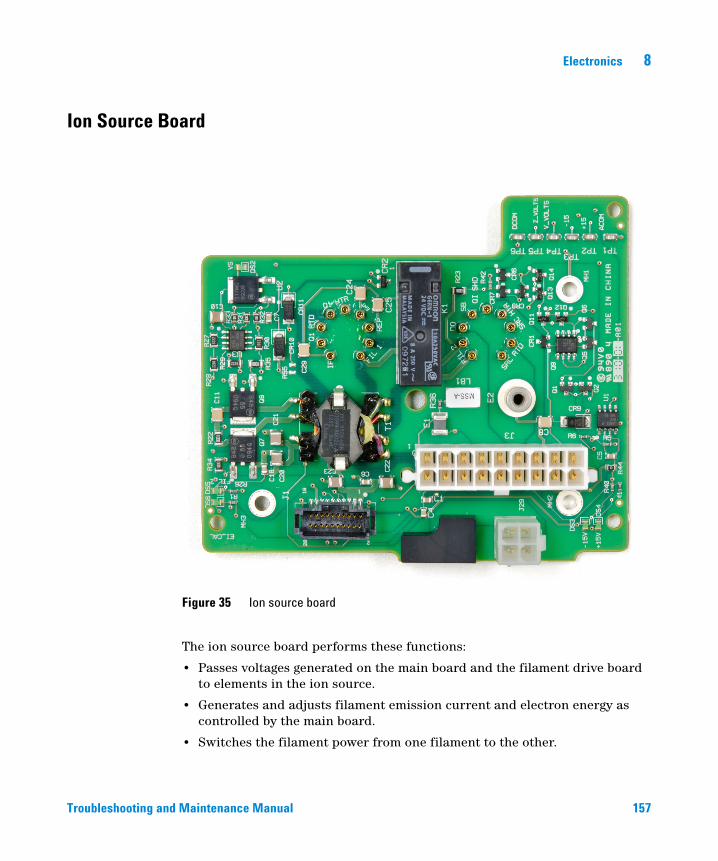
Electronics 8
Ion Source Board
Troubleshooting and
The ion source board performs these functions:
• Passes voltages generated on the main board and the filament drive board to elements in the ion source.
• Generates and adjusts filament emission current and electron energy as controlled by the main board.
• Switches the filament power from one filament to the other.
Figure 35 Ion source board
Maintenance Manual 157
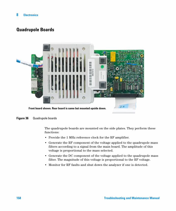
8 Electronics
Quadrupole Boards
Figure 36 Quadrupole boards
Front board shown. Rear board is same but mounted upside down.
158
The quadrupole boards are mounted on the side plates. They perform these functions:
• Provide the 1 MHz reference clock for the RF amplifier.
• Generate the RF component of the voltage applied to the quadrupole mass filters according to a signal from the main board. The amplitude of this voltage is proportional to the mass selected.
• Generate the DC component of the voltage applied to the quadrupole mass filter. The magnitude of this voltage is proportional to the RF voltage.
• Monitor for RF faults and shut down the analyzer if one is detected.
Troubleshooting and Maintenance Manual
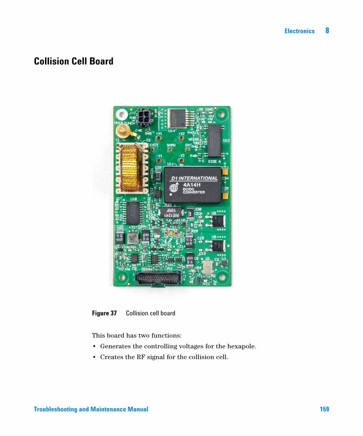
Electronics 8
Collision Cell Board
Troubleshooting and
This board has two functions:
• Generates the controlling voltages for the hexapole.
• Creates the RF signal for the collision cell.
Figure 37 Collision cell board
Maintenance Manual 159
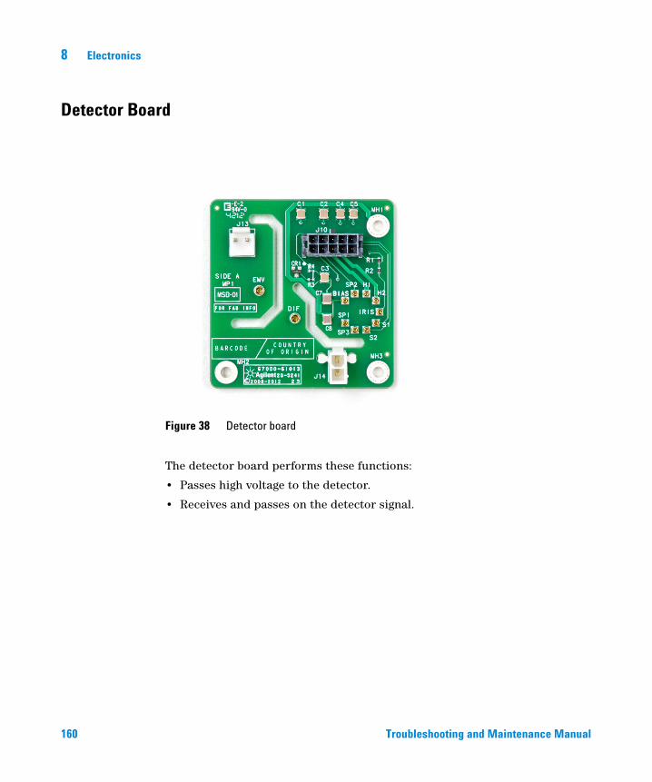
8 Electronics
Detector Board
160
The detector board performs these functions:
• Passes high voltage to the detector.
• Receives and passes on the detector signal.
Figure 38 Detector board
Troubleshooting and Maintenance Manual
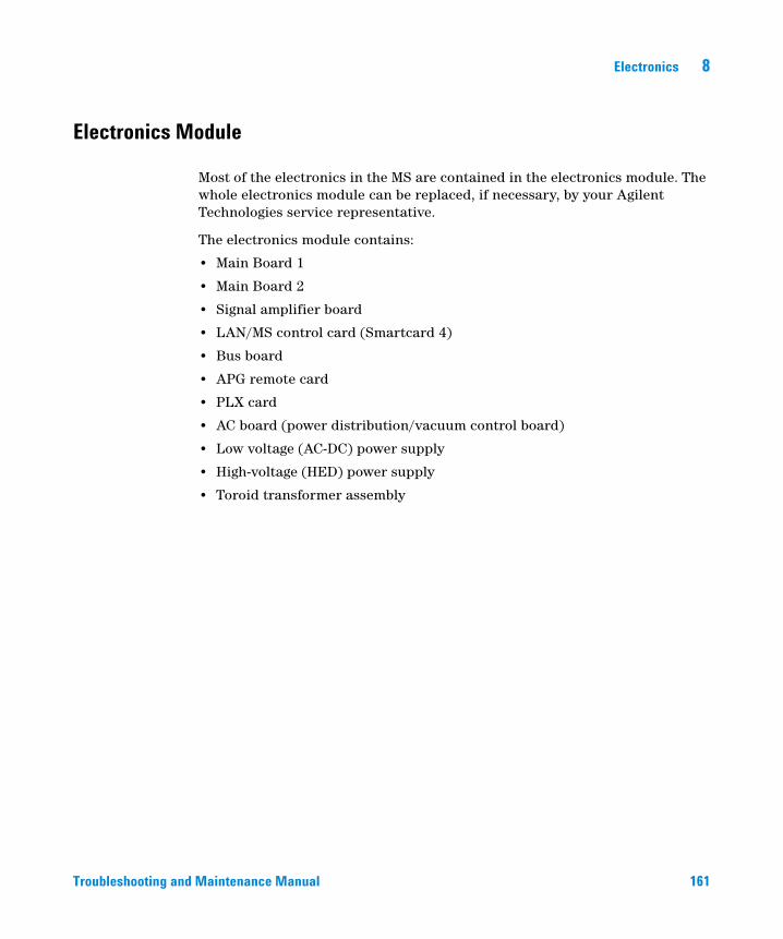
Electronics 8
Electronics Module
Troubleshooting and
Most of the electronics in the MS are contained in the electronics module. The whole electronics module can be replaced, if necessary, by your Agilent Technologies service representative.
The electronics module contains:
• Main Board 1
• Main Board 2
• Signal amplifier board
• LAN/MS control card (Smartcard 4)
• Bus board
• APG remote card
• PLX card
• AC board (power distribution/vacuum control board)
• Low voltage (AC-DC) power supply
• High-voltage (HED) power supply
• Toroid transformer assembly
Maintenance Manual 161
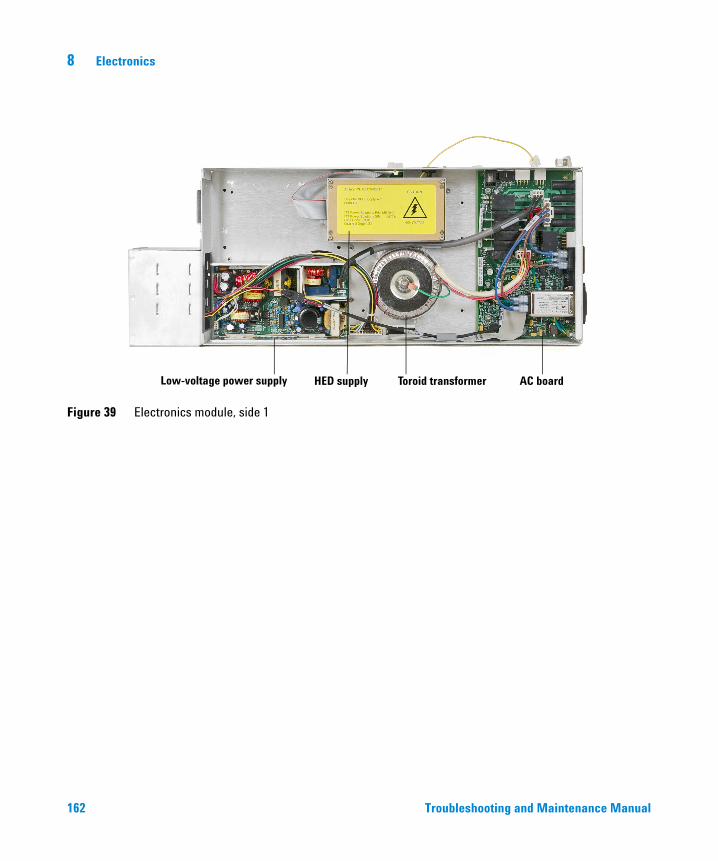
162
8 Electronics
Figure 39 Electronics module, side 1
HED supply Toroid transformer AC boardLow-voltage power supply
Troubleshooting and Maintenance Manual
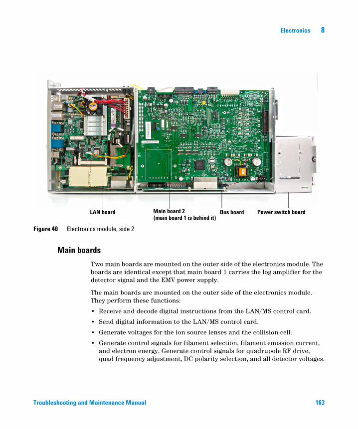
Electronics 8
Troubleshooting and
Main boards
Figure 40 Electronics module, side 2
LAN board Main board 2(main board 1 is behind it)
Bus board Power switch board
Two main boards are mounted on the outer side of the electronics module. The boards are identical except that main board 1 carries the log amplifier for the detector signal and the EMV power supply.
The main boards are mounted on the outer side of the electronics module. They perform these functions:
• Receive and decode digital instructions from the LAN/MS control card.
• Send digital information to the LAN/MS control card.
• Generate voltages for the ion source lenses and the collision cell.
• Generate control signals for filament selection, filament emission current, and electron energy. Generate control signals for quadrupole RF drive, quad frequency adjustment, DC polarity selection, and all detector voltages.
Maintenance Manual 163
164
8 Electronics
• Perform analog-to-digital conversion for the direct signal, ion source, and mass filter temperature signals, and foreline pressure or turbo pump speed signal.
• Monitor the signals from the vacuum system and fans and the filament status, HV fault and RF fault signals from the quadrupole board. Activate the shutdown line when the analyzer electronics must be disabled.
• Generate the control signals (on and off) used by the AC board for the high-vacuum pump and calibration valve.
• Generate ± 600 and ± 300 VDC (nominal) power for main board lens amplifiers and quadrupole board DC amplifiers.
• Supply and control the power for the ion source and quadrupole (mass filter) heaters.
• Provide 24 VDC power for the cooling fan.
Signal amplifier board
The log amplifier board amplifies the output of the detector. It produces an output voltage of 0 to 10 volts DC, proportional to the logarithm of the input current of 3 picoamps to 50 microamps.
An analog-to-digital converter converts the amplifier output voltage to digital information. The LAN/MS control card converts the data into abundance counts proportional to the detector signal current.
AC board
The AC board is mounted on the opposite side of the electronics panel from the LAN/MS CPU. The AC board is also sometimes called the power distribution/vacuum control board. It performs these functions:
• Provides input voltage transparency for the MS.
• Distributes AC line power to the AC/DC power supply, the foreline pump, and the turbo pump controller.
• Turns the calibration valve on or off as directed by the main board.
• Provides the voltage for the calibration valve.
• Provides a logic interface to turbo controller.
• Controls the foreline gauge.
Troubleshooting and Maintenance Manual
Electronics 8
Troubleshooting and
• Turns on the turbo pump once the foreline pressure is low enough, as directed by the main board.
• Turns off the turbo pump if the foreline pressure is too high.
• Passes the foreline pressure signal from the foreline gauge or turbo pump speed and other vacuum status information to the main board.
• Turns off the foreline pump in case of a problem with pumpdown.
Turbo pump control
Your MS is equipped with a turbo pump with an integrated controller.
The AC board sends control signals to, and receives turbo pump status information from, the turbo pump controller. The turbo pump controller provides power to the turbo pump and regulates pump speed.
If the pump fails to reach 80% speed within 10 minutes after beginning pumpdown or if the speed drops below 50% during operation, the controller shuts off the turbo pump and the AC board shuts off the foreline pump.
Pumpdown failure shutdown
The AC board will shut down both the high-vacuum and the foreline pump if the system fails to pump down correctly. One condition that triggers shutdown is turbo pump speed below 80% after 10 minutes, or if the foreline pressure is above 300 mTorr after 10 minutes.
This is usually because of a large air leak: either the side plate has not sealed correctly or the vent valve is still open. This feature helps prevent the foreline pump from sucking air through the system, which can damage the analyzer and pump.
To correct the problem, power cycle the MS and troubleshoot. You have 10 minutes to find and correct the air leak before the system shuts down again. Be sure to press on the side plate when turning on the MS power to ensure a good seal.
Maintenance Manual 165
8 Electronics
Bus board
166
This board is mounted on the bottom of the electronics module. It acts as a bus connecting the two main boards.
PLX card
This card, located inside the SmartCard module, provides fast communications between the processor module and other parts of the MS system. It speeds up the entire system by removing communications tasks from the central processor.
LAN/MS Control Card (Smartcard 4)
The LAN/MS control card is located to the left of Main Boards 1 and 2 on the electronics panel. The LAN/MS control card has two main functions:
• Provide a communication interface between the MS and the data system
• Provide real-time control of the MS, freeing the data system for other tasks
Functional areas of the LAN/MS control card include:
• Instrument controller
• Data processor
• Main processor
• Serial communication processor
• Network communication controller
• Remote start processor
• Random access memory (RAM)
• Status LEDs
LEDs on the LAN/MS control card are visible near the LAN connector on the rear panel.
Troubleshooting and Maintenance Manual
Electronics 8
Power Supplies
Low-voltage (AC-DC) power supply
Troubleshooting and
The low voltage power supply is mounted next to the toroid transformer in the electronics module. A universal input power supply, it converts AC line voltage into the DC voltages used by the rest of the electronics. The power supply generates the following DC voltages:
• +24 V (nominal)
• +15 V (nominal)
• –15 V (nominal)
• +5 V (nominal)
High-voltage (HED) power supply
The high-voltage power supply provides the –10,000 volts DC for the high-energy dynode (HED) in the detector for the EI MS. The HED power supply also provides 600 VDC for the detector focus lens. Due to the high impedance of this circuit, measuring the detector focus voltage with a handheld voltmeter will give a typical reading of 90 to 100 volts where the polarity matches that of the HED voltage.
Toroid transformer
The toroid transformer is mounted next to the AC board. It provides 24 VAC for the mass filters and source heater circuits. The input wires take 120 VAC or 200 to 260 VAC from the AC board. The line voltage switch on the top of the electronics module straps the toroid primary. The output wires connect to the AC board.
Maintenance Manual 167
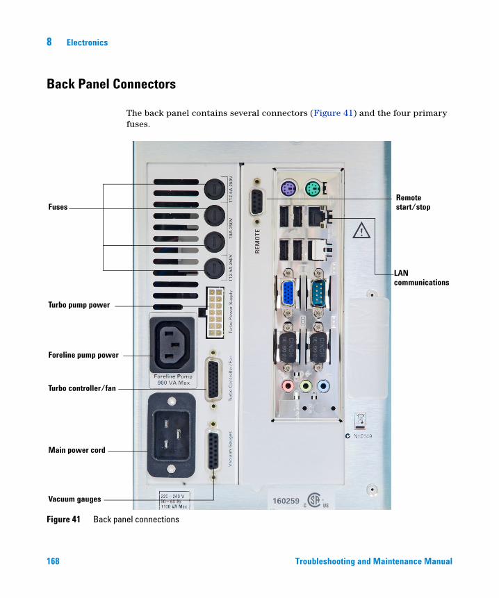
8 Electronics
Back Panel Connectors
168
The back panel contains several connectors (Figure 41) and the four primary fuses.
Figure 41 Back panel connections
Fuses
Turbo pump power
Foreline pump power
Turbo controller/fan
Main power cord
Vacuum gauges
Remotestart/stop
LANcommunications
Troubleshooting and Maintenance Manual
Electronics 8
Primary fuses
Troubleshooting and
The four primary fuses limit current into the MS in case of a short circuit in the foreline pump. Fuse values are shown on the panel.
Turbo pump power receptacle
The turbo pump power receptacle provides power for the turbo pump.
Foreline pump power receptacle
The foreline pump power cord receptacle provides AC power for the foreline pump. If the power switch is off, no power is supplied to the foreline pump.
Turbo controller / fan receptacle
This provides power and control for the turbo pump controller and the turbo pump cooling fan.
Main power cord receptacle
The AC power cord brings in all electrical power for the MS. The power cord can be detached from the MS.
Vacuum gauge connector
This connector powers the two vacuum gauges and connects their signals to the controlling electronics.
Remote start connector
The remote start connector is the external connector for the remote start circuitry on the LAN/MS control card. It receives remote start signals from the GC.
LAN (I/O) connector
The LAN cable from the data system is connected to the LAN communications connector. It carries all data communication between the PC and the MS.
Maintenance Manual 169
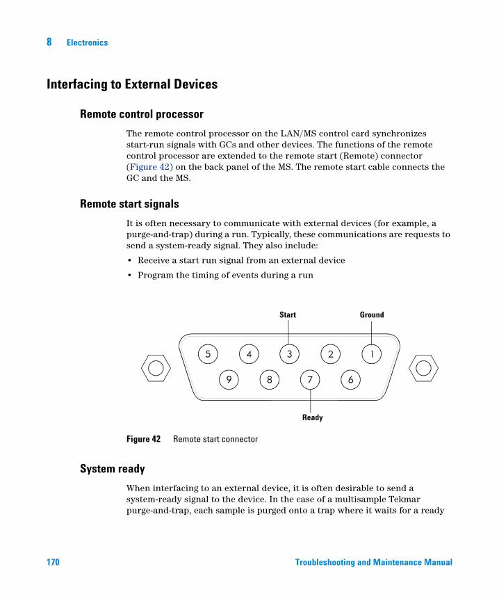
8 Electronics
Interfacing to External Devices
Remote control processor
170
The remote control processor on the LAN/MS control card synchronizes start-run signals with GCs and other devices. The functions of the remote control processor are extended to the remote start (Remote) connector (Figure 42) on the back panel of the MS. The remote start cable connects the GC and the MS.
Remote start signals
It is often necessary to communicate with external devices (for example, a purge-and-trap) during a run. Typically, these communications are requests to send a system-ready signal. They also include:
• Receive a start run signal from an external device
• Program the timing of events during a run
Figure 42 Remote start connector
Start Ground
Ready
System ready
When interfacing to an external device, it is often desirable to send a system-ready signal to the device. In the case of a multisample Tekmar purge-and-trap, each sample is purged onto a trap where it waits for a ready
Troubleshooting and Maintenance Manual
Electronics 8
Troubleshooting and
signal. On receipt of the ready signal, the desorbtion cycle begins. When a specific temperature is reached, the purge-and-trap closes a contact to indicate the run has started.
The ready pin on the remote start connector on the GC is held low at all times except when the GC, MS, and data system are all ready. On system ready, a logic high of 5 VDC is present between that pin and any ground. This same high can be detected between the ready and ground pins on the remote start connector on the MS.
Start run input
The best way to generate a start run signal is to use the remote start connector on the GC. Since remote start cables are made for most common devices, this is often the simplest way. A general-purpose remote start cable (05890-61080), is also available that terminates in spade lugs. Care must be taken to ensure that the system is actually ready before the start run signal is sent.
If necessary, the remote start connector on the back of the MS can be used to send the start run signal. A contact closure between the start and ground pins will start the run if the system is ready.
Maintenance Manual 171

172
8 Electronics
Troubleshooting and Maintenance Manual
Agilent 7000 Series Triple Quadrupole GC/MS Troubleshooting and Maintenance Manual
9Replacement Parts
To Order Parts 174
Electronics 175
Vacuum System 176
Analyzer 178
EI GC/MS Interface 183
Consumables and Maintenance Supplies 184
Additional CI Parts 188
This chapter lists parts that can be ordered for use in maintaining your 7000 Triple Quad GC/MS. It includes user-replaceable parts only.
173Agilent Technologies
9 Replacement Parts
To Order Parts
174
To order parts for your MS, address the order or inquiry to your local Agilent Technologies office. Supply them with the following information:
• Model and serial number of your MS, located on a label on the lower left side near the front of the instrument.
• Part number(s) of the part(s) needed
• Quantity of each part needed
Some parts are available as rebuilt assemblies
Rebuilt assemblies pass all the same tests and meet all the same specifications as new parts. Rebuilt assemblies can be identified by their part numbers. The first two digits of the second part of the part number are 69 or 89 (such as xxxxx-69xxx or xxxxx-89xxx). Rebuilt assemblies are available on an exchange-only basis. When you return the original part to Agilent Technologies (after you receive the rebuilt assembly) you will receive a credit.
If you cannot find a part you need
If you need a part that is not listed in this chapter, check the Agilent Technologies Analytical Supplies Catalog or the online catalog on the Worldwide Web at http://www.agilent.com/chem. If you still cannot find it, contact your Agilent Technologies service representative or your Agilent Technologies office.
Troubleshooting and Maintenance Manual
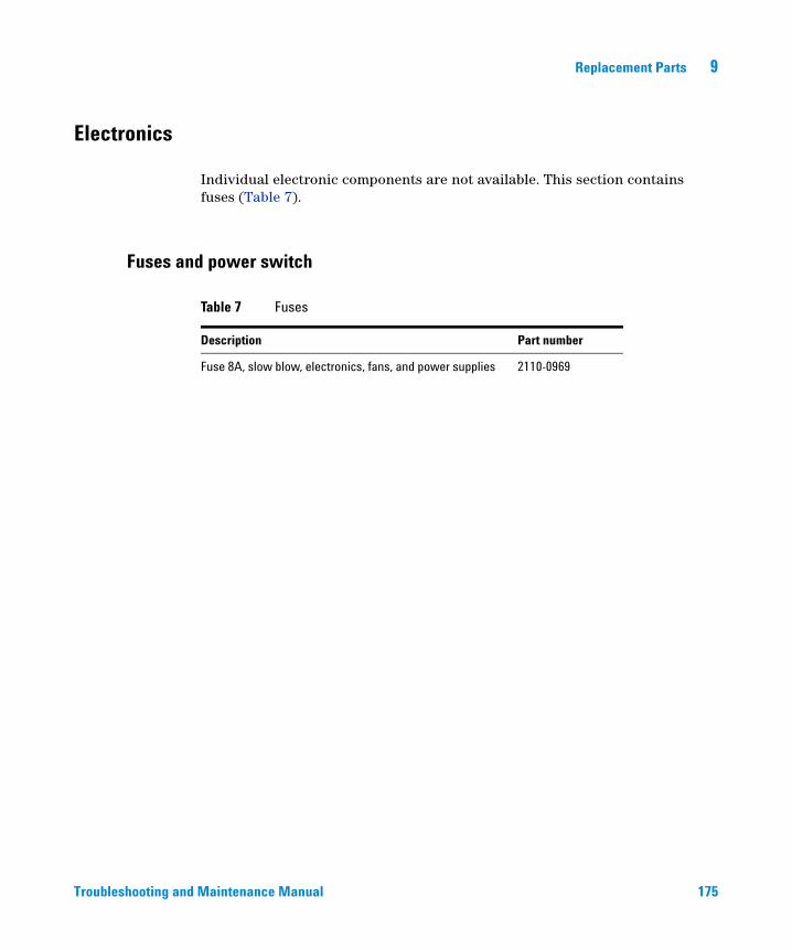
Replacement Parts 9
Electronics
Troubleshooting and
Individual electronic components are not available. This section contains fuses (Table 7).
Fuses and power switch
Table 7 Fuses
Description Part number
Fuse 8A, slow blow, electronics, fans, and power supplies 2110-0969
Maintenance Manual 175
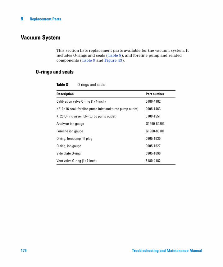
9 Replacement Parts
Vacuum System
176
This section lists replacement parts available for the vacuum system. It includes O-rings and seals (Table 8), and foreline pump and related components (Table 9 and Figure 43).
O-rings and seals
Table 8 O-rings and seals
Description Part number
Calibration valve O-ring (1/4-inch) 5180-4182
KF10/16 seal (foreline pump inlet and turbo pump outlet) 0905-1463
KF25 O-ring assembly (turbo pump outlet) 0100-1551
Analyzer ion gauge G1960-80303
Foreline ion gauge G1960-80101
O-ring, forepump fill plug 0905-1630
O-ring, ion gauge 0905-1627
Side plate O-ring 0905-1690
Vent valve O-ring (1/4-inch) 5180-4182
Troubleshooting and Maintenance Manual
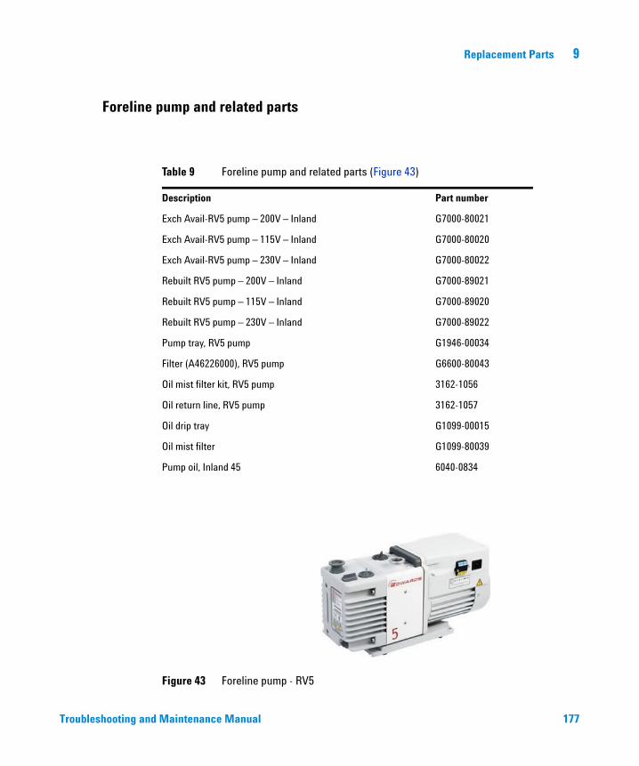
Replacement Parts 9
Foreline pump and related parts
Troubleshooting and
Table 9 Foreline pump and related parts (Figure 43)
Description Part number
Exch Avail-RV5 pump – 200V – Inland G7000-80021
Exch Avail-RV5 pump – 115V – Inland G7000-80020
Exch Avail-RV5 pump – 230V – Inland G7000-80022
Rebuilt RV5 pump – 200V – Inland G7000-89021
Rebuilt RV5 pump – 115V – Inland G7000-89020
Rebuilt RV5 pump – 230V – Inland G7000-89022
Pump tray, RV5 pump G1946-00034
Filter (A46226000), RV5 pump G6600-80043
Oil mist filter kit, RV5 pump 3162-1056
Oil return line, RV5 pump 3162-1057
Oil drip tray G1099-00015
Oil mist filter G1099-80039
Pump oil, Inland 45 6040-0834
Figure 43 Foreline pump - RV5
Maintenance Manual 177
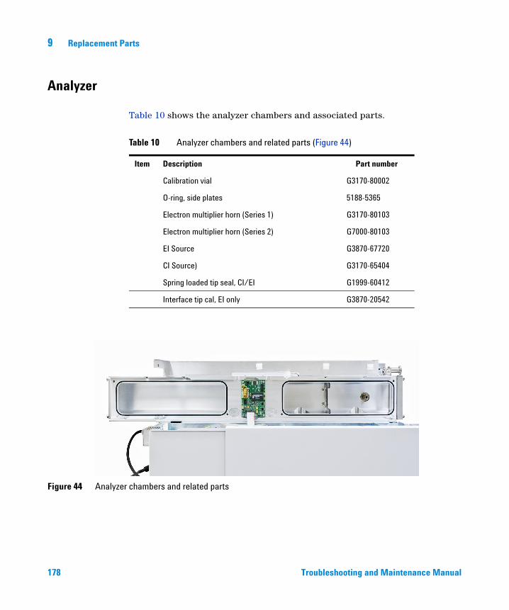
9 Replacement Parts
Analyzer
178
Table 10 shows the analyzer chambers and associated parts.
Table 10 Analyzer chambers and related parts (Figure 44)
Item Description Part number
Calibration vial G3170-80002
O-ring, side plates 5188-5365
Electron multiplier horn (Series 1) G3170-80103
Electron multiplier horn (Series 2) G7000-80103
EI Source G3870-67720
CI Source) G3170-65404
Spring loaded tip seal, CI/EI G1999-60412
Interface tip cal, EI only G3870-20542
Figure 44 Analyzer chambers and related parts
Troubleshooting and Maintenance Manual
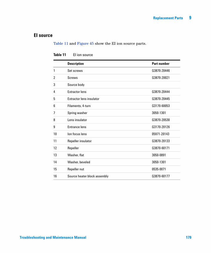
Replacement Parts 9
EI source
Troubleshooting and
Table 11 and Figure 45 show the EI ion source parts.
Table 11 EI ion source
Description Part number
1 Set screws G3870-20446
2 Screws G3870-20021
3 Source body
4 Extractor lens G3870-20444
5 Extractor lens insulator G3870-20445
6 Filaments, 4-turn G3170-60053
7 Spring washer 3050-1301
8 Lens insulator G3870-20530
9 Entrance lens G3170-20126
10 Ion focus lens 05971-20143
11 Repeller insulator G3870-20133
12 Repeller G3870-60171
13 Washer, flat 3050-0891
14 Washer, beveled 3050-1301
15 Repeller nut 0535-0071
16 Source heater block assembly G3870-60177
Maintenance Manual 179
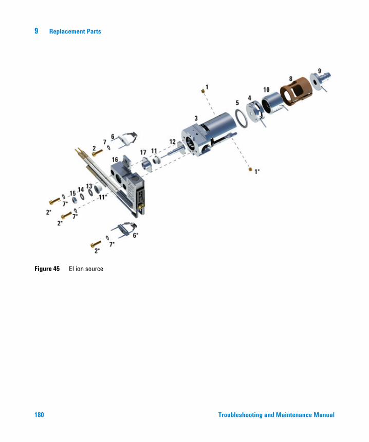
9 Replacement Parts
Figure 45 EI ion source
180 Troubleshooting and Maintenance Manual
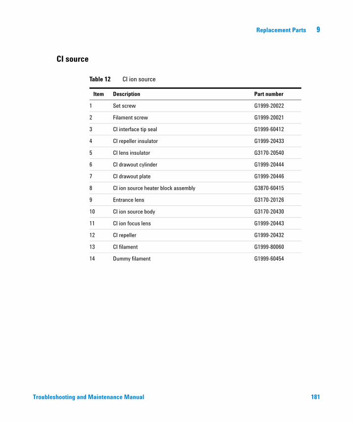
Replacement Parts 9
CI source
Troubleshooting and
Table 12 CI ion source
Item Description Part number
1 Set screw G1999-20022
2 Filament screw G1999-20021
3 CI interface tip seal G1999-60412
4 CI repeller insulator G1999-20433
5 CI lens insulator G3170-20540
6 CI drawout cylinder G1999-20444
7 CI drawout plate G1999-20446
8 CI ion source heater block assembly G3870-60415
9 Entrance lens G3170-20126
10 CI ion source body G3170-20430
11 CI ion focus lens G1999-20443
12 CI repeller G1999-20432
13 CI filament G1999-80060
14 Dummy filament G1999-60454
Maintenance Manual 181
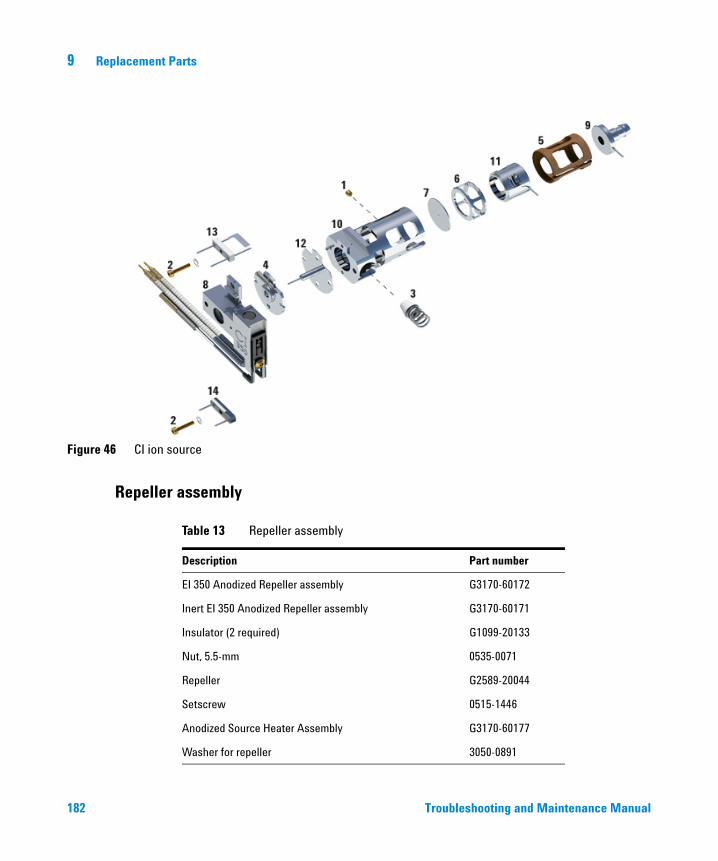
9 Replacement Parts
Repeller assembly
Figure 46 CI ion source
182
Table 13 Repeller assembly
Description Part number
EI 350 Anodized Repeller assembly G3170-60172
Inert EI 350 Anodized Repeller assembly G3170-60171
Insulator (2 required) G1099-20133
Nut, 5.5-mm 0535-0071
Repeller G2589-20044
Setscrew 0515-1446
Anodized Source Heater Assembly G3170-60177
Washer for repeller 3050-0891
Troubleshooting and Maintenance Manual
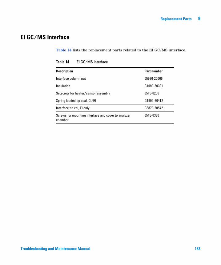
Replacement Parts 9
EI GC/MS Interface
Troubleshooting and
Table 14 lists the replacement parts related to the EI GC/MS interface.
Table 14 EI GC/MS interface
Description Part number
Interface column nut 05980-20066
Insulation G1099-20301
Setscrew for heater/sensor assembly 0515-0236
Spring loaded tip seal, CI/EI G1999-60412
Interface tip cal, EI only G3870-20542
Screws for mounting interface and cover to analyzer chamber
0515-0380
Maintenance Manual 183
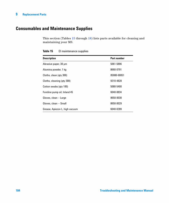
9 Replacement Parts
Consumables and Maintenance Supplies
184
This section (Tables 15 through 18) lists parts available for cleaning and maintaining your MS.
Table 15 EI maintenance supplies
Description Part number
Abrasive paper, 30 µm 5061-5896
Alumina powder, 1 kg 8660-0791
Cloths, clean (qty 300) 05980-60051
Cloths, cleaning (qty 300) 9310-4828
Cotton swabs (qty 100) 5080-5400
Foreline pump oil, Inland 45 6040-0834
Gloves, clean – Large 8650-0030
Gloves, clean – Small 8650-0029
Grease, Apiezon L, high vacuum 6040-0289
Troubleshooting and Maintenance Manual
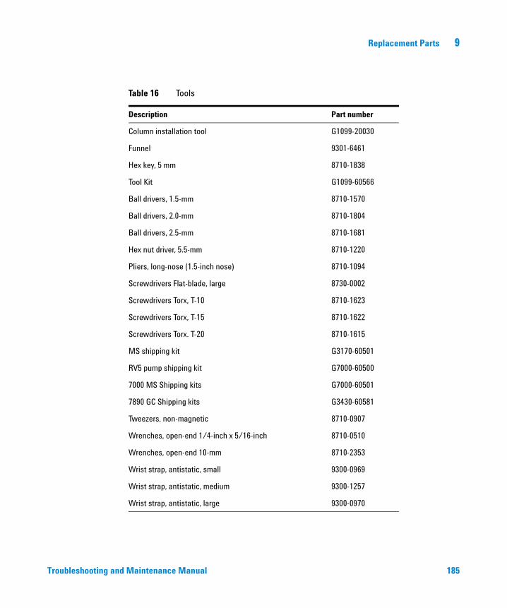
Replacement Parts 9
Troubleshooting and
Table 16 Tools
Description Part number
Column installation tool G1099-20030
Funnel 9301-6461
Hex key, 5 mm 8710-1838
Tool Kit G1099-60566
Ball drivers, 1.5-mm 8710-1570
Ball drivers, 2.0-mm 8710-1804
Ball drivers, 2.5-mm 8710-1681
Hex nut driver, 5.5-mm 8710-1220
Pliers, long-nose (1.5-inch nose) 8710-1094
Screwdrivers Flat-blade, large 8730-0002
Screwdrivers Torx, T-10 8710-1623
Screwdrivers Torx, T-15 8710-1622
Screwdrivers Torx. T-20 8710-1615
MS shipping kit G3170-60501
RV5 pump shipping kit G7000-60500
7000 MS Shipping kits G7000-60501
7890 GC Shipping kits G3430-60581
Tweezers, non-magnetic 8710-0907
Wrenches, open-end 1/4-inch x 5/16-inch 8710-0510
Wrenches, open-end 10-mm 8710-2353
Wrist strap, antistatic, small 9300-0969
Wrist strap, antistatic, medium 9300-1257
Wrist strap, antistatic, large 9300-0970
Maintenance Manual 185
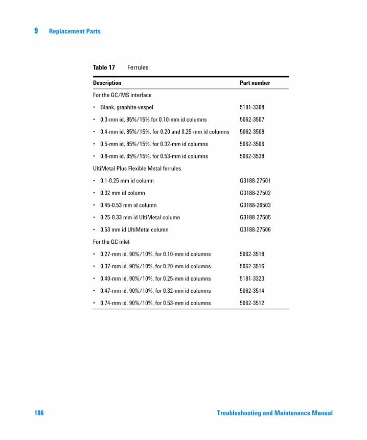
186
9 Replacement Parts
Table 17 Ferrules
Description Part number
For the GC/MS interface
• Blank, graphite-vespel 5181-3308
• 0.3-mm id, 85%/15% for 0.10-mm id columns 5062-3507
• 0.4-mm id, 85%/15%, for 0.20 and 0.25-mm id columns 5062-3508
• 0.5-mm id, 85%/15%, for 0.32-mm id columns 5062-3506
• 0.8-mm id, 85%/15%, for 0.53-mm id columns 5062-3538
UltiMetal Plus Flexible Metal ferrules
• 0.1-0.25 mm id column G3188-27501
• 0.32 mm id column G3188-27502
• 0.45-0.53 mm id column G3188-26503
• 0.25-0.33 mm id UltiMetal column G3188-27505
• 0.53 mm id UltiMetal column G3188-27506
For the GC inlet
• 0.27-mm id, 90%/10%, for 0.10-mm id columns 5062-3518
• 0.37-mm id, 90%/10%, for 0.20-mm id columns 5062-3516
• 0.40-mm id, 90%/10%, for 0.25-mm id columns 5181-3323
• 0.47-mm id, 90%/10%, for 0.32-mm id columns 5062-3514
• 0.74-mm id, 90%/10%, for 0.53-mm id columns 5062-3512
Troubleshooting and Maintenance Manual
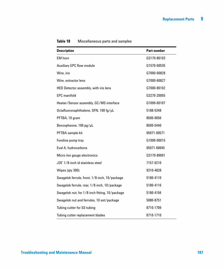
Replacement Parts 9
Troubleshooting and
Table 18 Miscellaneous parts and samples
Description Part number
EM horn G3170-80103
Auxiliary EPC flow module G1570-60535
Wire, iris G7000-60828
Wire, extractor lens G7000-60827
HED Detector assembly, with iris lens G7000-80102
EPC manifold G3270-20055
Heater/Sensor assembly, GC/MS interface G1099-60107
Octafluoronaphthalene, OFN, 100 fg/µL 5188-5348
PFTBA, 10 gram 8500-0656
Benzopheone, 100 pg/µL 8500-5440
PFTBA sample kit 05971-60571
Foreline pump tray G1099-00015
Eval A, hydrocarbons 05971-60045
Micro-Ion gauge electronics G3170-89001
J20’ 1/8-inch id stainless steel 7157-0210
Wipes (qty 300) 9310-4828
Swagelok ferrule, front, 1/8-inch, 10/package 5180-4110
Swagelok ferrule, rear, 1/8-inch, 10/package 5180-4116
Swagelok nut, for 1/8-inch fitting, 10/package 5180-4104
Swagelok nut and ferrules, 10 set/package 5080-8751
Tubing cutter for SS tubing 8710-1709
Tubing cutter replacement blades 8710-1710
Maintenance Manual 187
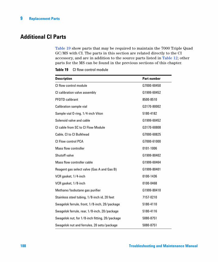
9 Replacement Parts
Additional CI Parts
188
Table 19 show parts that may be required to maintain the 7000 Triple Quad GC/MS with CI. The parts in this section are related directly to the CI accessory, and are in addition to the source parts listed in Table 12; other parts for the MS can be found in the previous sections of this chapter.
Table 19 CI flow control module
Description Part number
CI flow control module G7000-60450
CI calibration valve assembly G1999-60452
PFDTD calibrant 8500-8510
Calibration sample vial G3170-80002
Sample vial O-ring, 1/4-inch Viton 5180-4182
Solenoid valve and cable G1999-60452
CI cable from SC to CI Flow Module G3170-60808
Cable, CI to CI Bulkhead G7000-60825
CI Flow control PCA G7000-61000
Mass flow controller 0101-1006
Shutoff valve G1999-80402
Mass flow controller cable G1999-60464
Reagent gas select valve (Gas A and Gas B) G1999-80401
VCR gasket, 1/4-inch 0100-1436
VCR gasket, 1/8-inch 0100-0468
Methane/Isobutane gas purifier G1999-80410
Stainless steel tubing, 1/8-inch id, 20 feet 7157-0210
Swagelok ferrule, front, 1/8-inch, 20/package 5180-4110
Swagelok ferrule, rear, 1/8-inch, 20/package 5180-4116
Swagelok nut, for 1/8-inch fitting, 20/package 5080-8751
Swagelok nut and ferrules, 20 sets/package 5080-8751
Troubleshooting and Maintenance Manual


Agilent Technologies
© Agilent Technologies, Inc.
Printed in USA, August 2013


