Embed Size (px)
Citation preview
ORIGINAL ARTICLE
Agent-based middleware architecture for reconfigurablemanufacturing systems
Rafael Priego1 & Nagore Iriondo1 & Unai Gangoiti1 & Marga Marcos1
Received: 2 August 2016 /Accepted: 9 February 2017 /Published online: 15 March 2017# The Author(s) 2017. This article is published with open access at Springerlink.com
Abstract Modern manufacturing systems are expected to beflexible and efficient in order to cope with challenging marketdemands. Thus, they must be flexible enough as to meet chang-ing requirements such as changes in production, energy efficien-cy, performance optimization, fault tolerance to process or con-troller faults, among others. Demanding requirements can bedefined as a set of quality of service (QoS) requirements to bemet. This paper proposes a generic and customizable multi-agentarchitecture that, making use of distributed agents, monitorsQoS, triggering, if needed, a reconfiguration of the control sys-tem to recover QoS. As a proof of concept, the architecture hasbeen implemented to provide availability of the control systemunderstood as service continuity. The prototype has been testedin a case study consisting of an assembly cell where assessmentof the approach has been conducted.
Keywords Multi-agent systems .Middleware . Quality ofservice .Controlsystemavailability .Dynamicreconfiguration
1 Introduction
In recent years, there has been an increase on the investmenteffort from public institutions to reinforce or recover themanufacturing industries. This sector offers a suitable oppor-tunity for increasing innovation, economic growth and jobcreation. Initiatives such as Factory of the Future in theEuropean Union [1], the Industrie 4.0 initiative driven by theGerman Federal Government [2] and the so-called AdvancedManufacturing launched by the US Government [3] are clearexamples. All these initiatives pursue the implementation ofhigh-tech manufacturing processes based on the use of adap-tive and smart manufacturing equipment and systems, aimingat automating, controlling and optimizing the processes, en-suring plant availability while providing high quality produc-tion with zero defects.
The achievement of these objectives requires automationproduction system to exhibit the ability to self-reconfigure tomeet quality of service (QoS) requirements. Reconfigurationmechanisms provide the system with the ability of switchingfrom one configuration to another, improving the efficiency ofthe system with respect to sudden changes on customer de-mands and/or unpredictable events, like failure or disruptions.
Different works can be found in the literature dealing withflexibility in manufacturing systems. Some of these worksdeal with the use of reconfiguration mechanisms at productionlevel by implementing different mechanisms to optimize theproduction process. For instance, Morenas, Higuera andAlonso [4] assign priority to products based on the particularcustomer, the deadline of the order and the order of arrival. Onthe other hand, Nouri [5] uses other parameters such as ma-chine workload, material handling, operational time and oper-ation sequence of the parts, among others. Other works usesthe re-scheduling to reduce global energy consumption [6] orto deal with machine or actuator failures [7, 8].
* Rafael [email protected]
Nagore [email protected]
Unai [email protected]
Marga [email protected]
1 Department of Automatic Control and System Engineering,University of the Basque Country, C/Alameda Urquijo s/n,48013 Bilbao, Spain
Int J Adv Manuf Technol (2017) 92:1579–1590DOI 10.1007/s00170-017-0154-z
Other focus of research is the dynamic reconfiguration of thecontrol system. Botygin and Tartakovsky [9] optimize theworkload of the system controllers following a dynamic rank-ing table. In a similar way, Binotto et al. [10] balance the task ofeach controller based on order arrival time and the currentworkload of the controllers. In [11], the goal of the workloadbalance is to optimize energy efficiency. Reconfiguration hasalso used in order to add fault tolerance to the automation sys-tem, either to controller faults [12] or to network failures [13].
Thus, QoS is understood in different ways, from optimiz-ing the manufacturing orders to meet order requirements(deadlines, customer, etc.) to optimizing production efficien-cy, energy efficiency or response to process or controllerfaults. But they have in common the reconfiguration of theautomation system. All these works aim at ensuring a specificQoS (production optimization, process fault tolerance, con-troller failure tolerance, workload balance, among others) byoffering a custom solution to the concrete issue. This papercontributes a generic architecture identifying the key compo-nents to deal with QoS loss detection and reaction that can becustomized for different QoS goals including the onescommented above.
It generalizes and formalizes previous works of authors.[14] presents a preliminary work on a multi-agent system(MAS) which provides fault tolerance to controller faults, re-covering the whole execution in other controller. [15] intro-duces the concept of Mechatronic Component (MC) as thecode in charge of controlling a part of the process, and itanalyzes when it is possible to recover its functionality aftera controller fault. In [16], the concept of backup MC for statetracking is proposed. The novel contributions of this work gobeyond them as follows:
& It formulates the MC concept giving guidelines to thedeveloper to define it, identifying the non-recoverable ex-ecution states.
& It proposes a MAS-based implementation of the completesystem architecture, identifying and defining differenttypes of agents with specific roles.
& It defines code templates for MCs.
The paper also presents, as a proof of concept, amiddleware prototype that implements the control systemavailability under controller failures, recovering the set ofMCs of failed controllers in others. The proposed genericarchitecture can be customized for other QoS, preventing thatthey can be measured from the state of the automation system,such as the QoS definition analysed in the literature (processfaults, production efficiency, etc.).
The remainder of the paper is as follows: Section 2 presentsrelated work focusing on how the reconfiguration mecha-nisms are implemented. Section 3 formulates the concept ofmechatronic component extending previous definitions in the
literature to add the possible execution states. These latterinform about when the state of the MC can be derived fromthe current automation system state and, thus, reconfigurationactions can be performed. Section 4 presents the agent-basedimplementation of the runtime platform, i.e. the middlewarecomponents that, making use of an ontology proposal, imple-ment QoS monitoring and QoS recovering. Section 5 is ded-icated to a case study where illustrative examples are assessed.Finally, Section 6 outlines the most important conclusions andfuture work.
2 Related work
This section analyses the different technologies used forimplementing reconfiguration mechanisms in manufacturing.Most of the works found use the IEC61499 standard [17].Unfortunately, its consolidation in industry has not been asexpected, being the IEC61131-3 standard [18] the most usedin industrial applications. Notwithstanding this, it is worthy tolook at how the reconfigurationmechanisms are implemented.
Olsen et al. [19] propose the reconfiguration of IEC61499control systems, by means of adding, removing or re-connecting the functional blocks (FB) of the application.The reconfiguration actions to cope with the different situa-tions, like machines or controller failures, must be previouslydefined by the user.
Khalgui and Mosbahi [20] extend the concept of addingand removing FB in order to allow the relocation of FBs intoother controllers. This relocation is based on moving the codeof the FB as well as its execution data (its state). This type ofreconfiguration is known as stateful reconfiguration. The au-thors propose an external multi-agent system that provides therelocation of the FBs. In a similar way, the so-called eCEDACapproach [21] implements the reconfiguration through the so-called reconfiguration execution control function block,which is able to generate a copy of an FB in other controller,as well as restoring their data, rearrange their communicationsand remove the old FB. On the other hand, Yan and Vyatkin[22] propose two new types of FB: the agent FB and thetransfer FB in charge of performing the reconfiguration.However, the application is responsible for performing themonitoring and detection of failures and, making use of themechanisms provided, reconfiguring the control system.
In [23, 13], FBs are duplicated in different controllers. Oneof the controllers acts as a master being in charge of monitoringcontroller and/or network failures, respectively, deciding whena duplicated FB must be activated from the last execution state.
Although, in other application areas, more generic archi-tectures that manage concurrently multiple types of QoS havebeen proposed, for instance in control systems [24], andhealthcare [25], as far as authors know, solutions proposedfor manufacturing systems only tackle specific type of QoS
1580 Int J Adv Manuf Technol (2017) 92:1579–1590
or offer mechanisms to be handled by the application. Besides,the implementation of such strategies in current IEC61131-3automation systems is not straightforward.
On the other hand, when a failure is detected, it is necessaryto determine the actions to be done on the production systembefore and after the reconfiguration takes place to preventinconsistency states. Lepuschitz et al. [7] studies this problemunder process instrumentation failures.
The present work takes these ideas and goes beyond integrat-ing them into a generic architecture that provides QoS manage-ment achieving, thus, production unaware reconfiguration.
3 Formulation of the mechatronic componentconcept
The concept of mechatronic component (MC) was first pro-posed by Thrambouilidis [26] as a component having a me-chanical part, an electronic part and a software part. Being amechatronic system, it is a network of mechatronic compo-nents that collaborate through appropriate links to achievesystem objectives. Lüder et al. [27] define mechatronical unitsas containers of relevant information required within the en-gineering of manufacturing systems (mechanical data, func-tional data, control data, economical data, technical data andothers). In this work, the concept is extended to representruntime information: In particular, the situations in which thecurrent state of the mechatronic component can be derivedfrom the current values of the software variables.
This information is fundamental to enable dynamic recon-figuration. In the case of using dynamic reconfiguration forassuring some type of QoS (such as, for instance, systemavailability or efficiency), it is necessary not only to monitorsuch QoS (using specific techniques such as for instance heartbeat or work load, respectively, in all controllers) but it is alsonecessary to assure that the reconfiguration is possible and themanufacturing process will not suffer unpredictable effects.For instance, if the work of controllers is unbalanced and itis necessary to transfer control tasks among controllers, thetransference of workload must be done at instant in which theproduction process will not be affected. This means that theoperation state of the process must be known by the controller.
Depending on the manufacturing process and the design ofthe automation production system, it is possible to distinguishthe following runtime situations [14]:
An operation state of the MC is non-critical if it may beactivated directly in another controller (after de-activation inthe current controller or after a controller failure) having asinitial state the last known state of the MC. On the contrary,critical states are those that are not fully represented by thecurrent values of the software variables of the MC, preventingactivation/de-activation of theMC in order to avoid unpredict-able process behaviour.
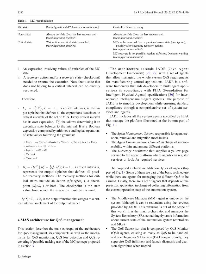
Table 1 summarizes when a MC reconfiguration, aiming atrecovering some QoS, can be launched attending at the MCstate. Note that recovering a MC from a controller failure is aspecial case in which a critical state has two variants: thosecases in which even the state is not completely known, theMCcould be re-started from a checkpoint state, and those in whichthe state is unpredictable, and thus, the MC cannot be re-started.
This extension of the MC concept leads to the follow-ing formulation. The overall control system is composedby a set of MCs that in turn is a set of elements containingrelevant information about the operating part of the sys-tem:
Sys ¼ MCif g ; i ¼ 1 : : : nMCi ¼ typesi; maini; Si;VIi;VOi; Σi; Ψi; δif g ; ð1Þ
where:
& typesi={Di, Pi} represents the set of data types (Di) andprogram organization unit (POU in the context of the IEC61331-3 software model) types (Pi) that compose the con-trol logic of the MCi.
& maini∈ typesi is the POU type of the main program fromwhich the rest of POU types of the MCi are instantiatedand used.
& Si is the set of variables corresponding to the MCi. Thevariables are characterized by their name and type, and inthe case of inputs and outputs, they are also characterizedby its physical address (2).
s ji ¼ name; type; address½ �ð Þ; s ji∈Si; i ¼ 1 ::: n MCs;j ¼ 1 : : : m state variables of MCi
ð2Þ
& VIi⊂Si is the set of inputs coming from the external world(process, operator, HMI, …) that correspond to globalvariables.
& VOi⊂Si is the set of outputs associated to the physicalvariables related to the physical part of the MCi, corre-sponding to global variables.
The rest of elements that compose the MC define the crit-ical states of the production system in which the MCmust notbe activated/de-activated as this action may lead to an incon-sistent state of the MC. As commented above, they can berepresented as the values of selected variables in Si. Note thata controller failure in any of these states will lead to a non-direct recovery.
Critical intervals are defined as the set of critical states thathave associated the same recovery method (checkpoint stateand/or recovery actions). The critical interval is characterizedby the following:
Int J Adv Manuf Technol (2017) 92:1579–1590 1581
i. An expression involving values of variables of the MCstate.
ii. A recovery action and/or a recovery state (checkpoint)needed to resume the execution. Note that a state thatdoes not belong to a critical interval can be directlyrecovered.
Therefore,
& Σi ¼ Σki
� �; k ¼ 1 ::: l critical intervals; is the in-
put alphabet that defines all the expressions associated tocritical intervals of the set of MCs. Every critical interval
has its own expression, Σki , that allows determining if an
execution state belongs to the interval. It is a Booleanexpression composed by arithmetic and logical operationsof state values following the grammar:
< Exp > ∷ ¼< Var >< arithmetic >< Value >��� < Exp >< logic >< Exp >
< arithmetic > ∷ ¼ ≤ ≥j j < >j j ¼< logic > ∷ ¼ OR
���AND
< Var > ∈S
< Value > ∈ℝ
& Ψi ¼ Ψki
� �j Ψki ¼ ξki ;λ
ki
� �; k ¼ 1::: l critical intervals;
represents the output alphabet that defines all possi-ble recovery methods. The recovery methods for crit-
ical states include an action (ξki ∈ typesi ), a check-
point (λki ⊂Si ) or both. The checkpoint is the state
value from which the execution must be resumed.
δi :Si×Σi→Ψi is the output function that assigns to a crit-ical interval an element of the output alphabet.
4 MAS architecture for QoS management
This section describes the main concepts of the architecturefor QoS management, its components as well as the mecha-nisms for QoS monitoring, QoS loss detection and QoS re-covering if possible making use of the MC concept proposedin Section 3.
The arch i tec ture ex tends JADE (Java AgentDEvelopment Framework) [28, 29] with a set of agentsthat allow managing the whole system QoS requirementsfor manufacturing control applications. JADE is a soft-ware framework that aids developers to build agent appli-cations in compliance with FIPA (Foundation forIntelligent Physical Agents) specifications [30] for inter-operable intelligent multi-agent systems. The purpose ofJADE is to simplify development while ensuring standardcompliance through a comprehensive set of system ser-vices and agents.
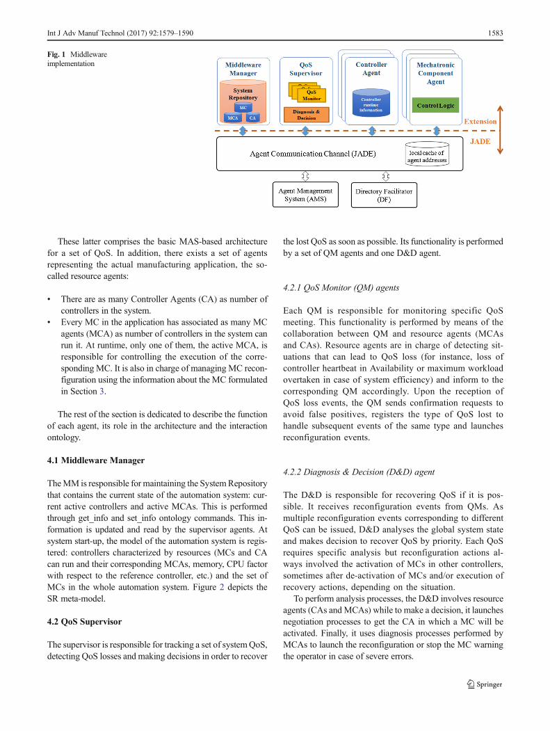
JADE includes all the system agents specified by FIPAthat manage the platform illustrated at the bottom part ofFig. 1:
& The Agent Management System, responsible for agent cre-ation, removal and migration mechanisms.
& The Agent Communication Channel, in charge of interop-erability within and among different platforms.
& The Directory Facilitator that supplies a yellow pageservice to the agent platform where agents can registerservices or look for required services.
The proposed architecture adds four types of agents (toppart of Fig. 1). Some of them are part of the basic architecturewhile there are agents for managing the different QoS to beassured. Finally, there are a set of agents that depends on theparticular application in charge of collecting information fromthe current operation state of the automation system.
& The Middleware Manager (MM) agent is unique on thesystem (although it can be redundant using the servicesprovided by JADE. This extension is out of the scope ofthis work). It is the main orchestrator and manages theSystem Repository (SR), containing dynamic informationabout current state of the automation system (controllersand MCs).
& The QoS Supervisor that is composed by QoS Monitor(QM) agents, existing as many as QoS to be handled,and one Diagnosis & Decision (D&D) agent. Jointly, theysupervise QoS fulfilment and launch diagnosis and deci-sion algorithms when needed.
Table 1 MC reconfiguration
MC state Reconfiguration (MC de-activation/activation) Controller failure recovery
Non-critical Always possible (from the last known state)(reconfiguration enabled)
Always possible (from the last known state).(reconfiguration enabled)
Critical state Wait until non-critical state is reached(reconfiguration disabled)
MC can be launched from a previous known state (checkpoint),possibly after executing recovery actions.
(reconfiguration enabled)
MC recovery is not possible. Action: safe stop. Operator warning.(reconfiguration disabled)
1582 Int J Adv Manuf Technol (2017) 92:1579–1590
These latter comprises the basic MAS-based architecturefor a set of QoS. In addition, there exists a set of agentsrepresenting the actual manufacturing application, the so-called resource agents:
& There are as many Controller Agents (CA) as number ofcontrollers in the system.
& Every MC in the application has associated as many MCagents (MCA) as number of controllers in the system canrun it. At runtime, only one of them, the active MCA, isresponsible for controlling the execution of the corre-sponding MC. It is also in charge of managing MC recon-figuration using the information about the MC formulatedin Section 3.
The rest of the section is dedicated to describe the functionof each agent, its role in the architecture and the interactionontology.
4.1 Middleware Manager
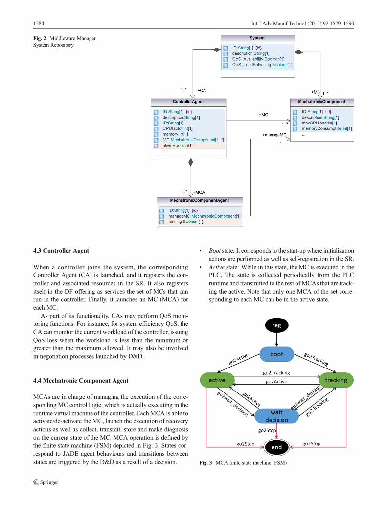
TheMM is responsible for maintaining the SystemRepositorythat contains the current state of the automation system: cur-rent active controllers and active MCAs. This is performedthrough get_info and set_info ontology commands. This in-formation is updated and read by the supervisor agents. Atsystem start-up, the model of the automation system is regis-tered: controllers characterized by resources (MCs and CAcan run and their corresponding MCAs, memory, CPU factorwith respect to the reference controller, etc.) and the set ofMCs in the whole automation system. Figure 2 depicts theSR meta-model.
4.2 QoS Supervisor
The supervisor is responsible for tracking a set of systemQoS,detecting QoS losses and making decisions in order to recover
the lost QoS as soon as possible. Its functionality is performedby a set of QM agents and one D&D agent.
4.2.1 QoS Monitor (QM) agents
Each QM is responsible for monitoring specific QoSmeeting. This functionality is performed by means of thecollaboration between QM and resource agents (MCAsand CAs). Resource agents are in charge of detecting sit-uations that can lead to QoS loss (for instance, loss ofcontroller heartbeat in Availability or maximum workloadovertaken in case of system efficiency) and inform to thecorresponding QM accordingly. Upon the reception ofQoS loss events, the QM sends confirmation requests toavoid false positives, registers the type of QoS lost tohandle subsequent events of the same type and launchesreconfiguration events.
4.2.2 Diagnosis & Decision (D&D) agent
The D&D is responsible for recovering QoS if it is pos-sible. It receives reconfiguration events from QMs. Asmultiple reconfiguration events corresponding to differentQoS can be issued, D&D analyses the global system stateand makes decision to recover QoS by priority. Each QoSrequires specific analysis but reconfiguration actions al-ways involved the activation of MCs in other controllers,sometimes after de-activation of MCs and/or execution ofrecovery actions, depending on the situation.
To perform analysis processes, the D&D involves resourceagents (CAs and MCAs) while to make a decision, it launchesnegotiation processes to get the CA in which a MC will beactivated. Finally, it uses diagnosis processes performed byMCAs to launch the reconfiguration or stop the MC warningthe operator in case of severe errors.
Fig. 1 Middlewareimplementation
Int J Adv Manuf Technol (2017) 92:1579–1590 1583
4.3 Controller Agent
When a controller joins the system, the correspondingController Agent (CA) is launched, and it registers the con-troller and associated resources in the SR. It also registersitself in the DF offering as services the set of MCs that canrun in the controller. Finally, it launches an MC (MCA) foreach MC.
As part of its functionality, CAs may perform QoS moni-toring functions. For instance, for system efficiency QoS, theCA can monitor the current workload of the controller, issuingQoS loss when the workload is less than the minimum orgreater than the maximum allowed. It may also be involvedin negotiation processes launched by D&D.
4.4 Mechatronic Component Agent
MCAs are in charge of managing the execution of the corre-sponding MC control logic, which is actually executing in theruntime virtual machine of the controller. EachMCA is able toactivate/de-activate the MC, launch the execution of recoveryactions as well as collect, transmit, store and make diagnosison the current state of the MC. MCA operation is defined bythe finite state machine (FSM) depicted in Fig. 3. States cor-respond to JADE agent behaviours and transitions betweenstates are triggered by the D&D as a result of a decision.
& Boot state: It corresponds to the start-up where initializationactions are performed as well as self-registration in the SR.
& Active state:While in this state, the MC is executed in thePLC. The state is collected periodically from the PLCruntime and transmitted to the rest ofMCAs that are track-ing the active. Note that only one MCA of the set corre-sponding to each MC can be in the active state.
Fig. 2 Middleware ManagerSystem Repository
Fig. 3 MCA finite state machine (FSM)
1584 Int J Adv Manuf Technol (2017) 92:1579–1590
& Tracking state: While in this state, the MCA receives andstores the current state of theMC, sent by the activeMCA.
& Wait decision state: During the reconfiguration process,the MCA remains in this state, and if required by theD&D, it can perform a diagnosis of the state.
& End state:When the MCA enters this state, after clean-uptasks are executed, the agent is removed.
Note that the functionality executed in every state by anMCA may be extended to handle different types of QoS. Forinstance, while in the tracking state, MCAs detect a possiblefailure of the active MCA if the state is not received within atimeout.
4.5 QoS management ontology
Agent communication is performed through messages follow-ing specific syntax and semantics known by the sender and thereceiver. The specific messages defined for QoS managementform the proposed ontology.
Three phases can be distinguished for assuring QoS: mon-itoring, loss detection and QoS recovering phases. All threeare performed by means of ontology messages exchange.
To illustrate the ontology, let us take, without losing gen-erality as every QoS is monitored, state is diagnosed and de-cision is made, the case of Availability QoS. Availability im-plies the service continuity or service recovery as soon aspossible and transparently to the application. The followingsub-sections illustrate the middleware operation in case ofcontroller failure from Availability monitoring, loss detectionunder a controller failure up to recovering its service on othercontrollers. Customized sequence diagrams (to includetimeouts) are used to show the messages exchange and theagents involved in each phase.
4.6 QoS monitoring
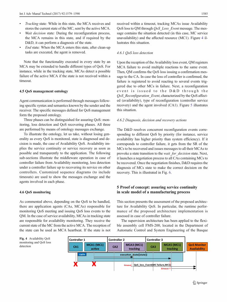
As commented above, depending on the QoS to be handled,there are application agents (CAs, MCAs) responsible formonitoring QoS meeting and issuing QoS loss events to theQM. In the case of service availability, MCAs in tracking stateare responsible for availability monitoring. They receive thecurrent state of theMC from the activeMCA. The reception ofthe state can be used as MCA heartbeat. If the state is not
received within a timeout, tracking MCAs issue AvailabilityQoS loss to QM throughQoS_Loss_Eventmessage. The mes-sage contains the situation detected (in this case, MC serviceunavailability) and the affected resource (MC1). Figure 4 il-lustrates this situation.
4.6.1 QoS loss detection
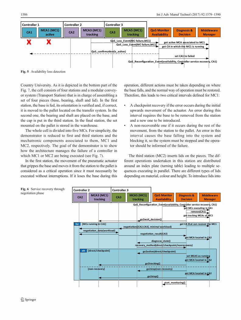
Upon the reception of the Availability loss event, QM registersMCA failure to avoid multiple reactions to the same event.Then, QM confirms the QoS loss issuing a confirmation mes-sage to the CA. In case the loss of controller is confirmed, thefailure is registered to avoid reacting to several events trig-gered due to other MCs in failure. Next, a reconfiguratione v e n t i s i s s u e d t o t h e D&D t h r o u g h t h eQoS_Reconfiguration_Event, characterized by the QoS affect-ed (availability), type of reconfiguration (controller servicerecovery) and the agent involved (CA1). Figure 5 illustratesthis situation.
4.6.2 Diagnosis, decision and recovery actions
The D&D resolves concurrent reconfiguration events corre-sponding to different QoS by priority (for instance, serviceavailability has higher priority than system efficiency). If itcorresponds to controller failure, it gets from the SR of theMCs to be recovered and issues messages to all their MCAs toprovoke a state transition to the wait_for_decision state. Next,it launches a negotiation process to all CAs containingMCs tobe recovered. Once the negotiation finishes, D&D requires thediagnosis of MCs state to make the correct decision on therecovery. This is illustrated in Fig. 6.
5 Proof of concept: assuring service continuityin scale model of a manufacturing process
This section presents the assessment of the proposed architec-ture for Availability QoS. In particular, the runtime perfor-mance of the proposed architecture implementation isassessed in case of controller failure.
The supervision architecture has been applied to the flexi-ble assembly cell FMS-200, located in the Department ofAutomatic Control and System Engineering of the Basque
cycle
Controller 2 Controller 3Controller 1
CA1 MCA1 (MC1) ac�ve CA2 MCA3 (MC1)
tracking CA3 MCA5 (MC1) tracking
QoS MonitorAvailability
xxexecu�on_state([state])
QoS_loss_Event(MC failure,MC1)�meout�meout
Fig. 4 Availability QoSmonitoring and QoS lossdetection
Int J Adv Manuf Technol (2017) 92:1579–1590 1585
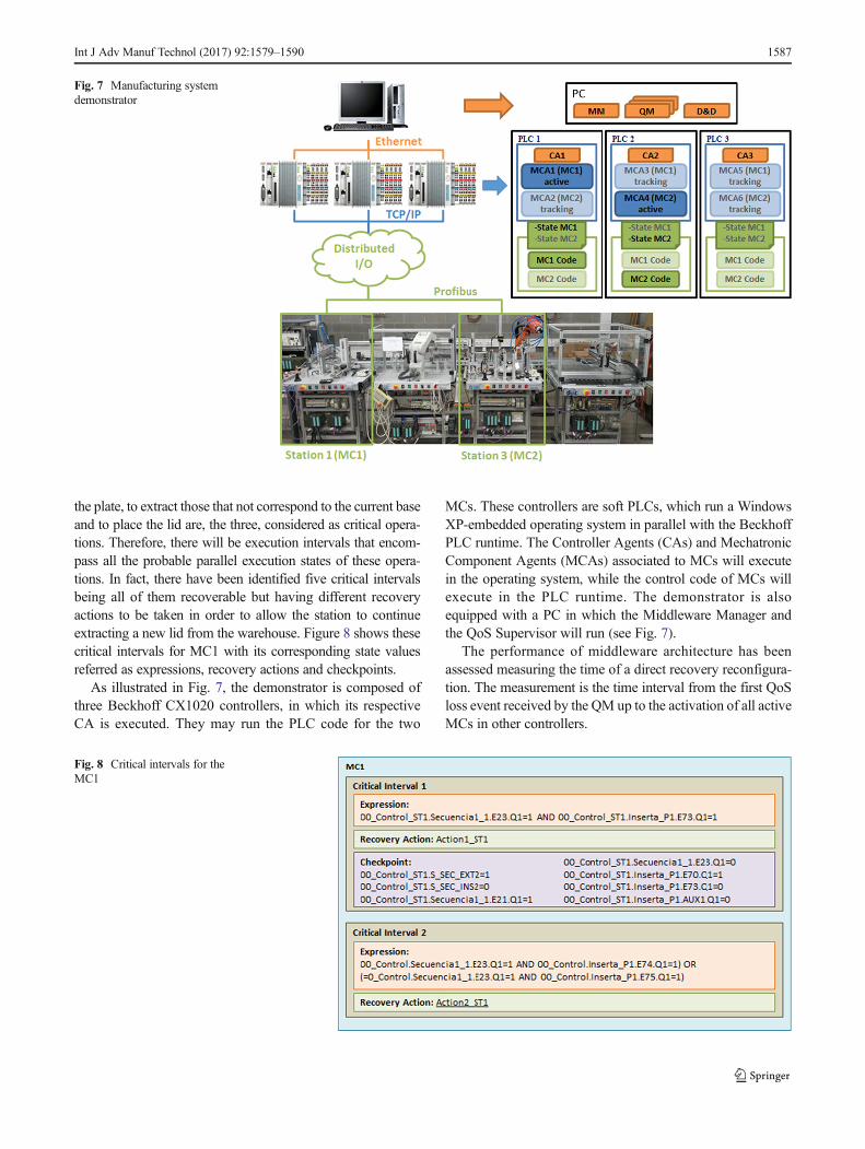
Country University. As it is depicted in the bottom part of theFig. 7, the cell consists of four stations and a modular convey-or system (Transport Station) that is in charge of assembling aset of four pieces (base, bearing, shaft and lid). In the firststation, the base is fed, its orientation is verified and, if correct,it is moved to the pallet located on the transfer system. In thesecond one, the bearing and shaft are placed on the base, andthe cap is put in the third station. In the final station, the setmounted on the pallet is stored in the warehouse.
The whole cell is divided into five MCs. For simplicity, thedemonstrator is reduced to first and third stations and themechatronic components associated to them, MC1 andMC2, respectively. The goal of the demonstrator is to showhow the architecture manages the failure of a controller inwhich MC1 or MC2 are being executed (see Fig. 7).
In the first station, the movement of the pneumatic actuatorthat grippes the base andmoves it from the station to the pallet isconsidered as a critical operation since it must necessarily beexecuted without interruptions. If it loses the base during this
operation, different actions must be taken depending on wherethe base falls, and the normal way of operationmust be restored.Therefore, this leads to two critical intervals defined for MC1:
& A checkpoint recovery if the error occurs during the initialupwards movement of the actuator. An error during thisinterval requires the base to be removed from the stationand a new one to be introduced.
& A non-recoverable one if it occurs during the rest of themovement, from the station to the pallet. An error in thisinterval causes the base falling into the system andblocking it, so the system must be stopped and the opera-tor should be informed of the failure.
The third station (MC2) inserts lids on the pieces. The dif-ferent operations undertaken in this station are distributedaround an index plate (turning table) leading to multiple se-quences executing in parallel. There are different types of lidsdepending onmaterial, colour and height. To introduce lids into
Controller 2 Controller 3Controller 1
CA1 MCA1 (MC1) ac�ve CA2 MCA3 (MC1)
tracking CA3 MCA5 (MC1) tracking
QoS MonitorAvailability
Diagnosis & Decision
Middleware Manager
QoS_Loss_Event(MC failure,MC1) get ac�ve MCA associated to MC1QoS_Loss_Event(MC failure,MC1)
get CA in which the MC1 is runningx
QoS_confirma�on(is_ac�ve)
x
QoS_Reconfigura�on_Event(availability, Controller service recovery, CA1)
set CA1 to failed
Fig. 5 Availability loss detection
Controller 2 Controller 3
CA2 MCA3 (MC1) tracking CA3 MCA5 (MC1)
trackingQoS MonitorAvailability
Diagnosis & Decision
Middleware Manager
get MCs execu�ng in CA1remove(CA1)
[MCs running in CA1] get CA that can recover the MC1for
get tracking MCAs of MC1go2wait_decision()
nego�a�on([CA2,CA3], minimal workload)nego�a�on_data(workload)
nego�a�on_result(CA3)
diagnose_state()recovery_method(direct/checkpoint/nonrecovery)
[direct/checkpoint]alt
get MCA located in CA3
go2ac�ve(direct/checkpoint)set MCA5 as running
get MCA located in CA2go2tracking()
[non-recovery] go2stop(non-recovery)
go2stop()
start_monitoring()
get MCA located in CA2
QoS_Reconfigura�on_Event(availability, Controller service recovery, CA1)
Fig. 6 Service recovery throughnegotiation phase
1586 Int J Adv Manuf Technol (2017) 92:1579–1590
the plate, to extract those that not correspond to the current baseand to place the lid are, the three, considered as critical opera-tions. Therefore, there will be execution intervals that encom-pass all the probable parallel execution states of these opera-tions. In fact, there have been identified five critical intervalsbeing all of them recoverable but having different recoveryactions to be taken in order to allow the station to continueextracting a new lid from the warehouse. Figure 8 shows thesecritical intervals for MC1 with its corresponding state valuesreferred as expressions, recovery actions and checkpoints.
As illustrated in Fig. 7, the demonstrator is composed ofthree Beckhoff CX1020 controllers, in which its respectiveCA is executed. They may run the PLC code for the two
MCs. These controllers are soft PLCs, which run a WindowsXP-embedded operating system in parallel with the BeckhoffPLC runtime. The Controller Agents (CAs) and MechatronicComponent Agents (MCAs) associated to MCs will executein the operating system, while the control code of MCs willexecute in the PLC runtime. The demonstrator is alsoequipped with a PC in which the Middleware Manager andthe QoS Supervisor will run (see Fig. 7).
The performance of middleware architecture has beenassessed measuring the time of a direct recovery reconfigura-tion. The measurement is the time interval from the first QoSloss event received by the QM up to the activation of all activeMCs in other controllers.
Fig. 7 Manufacturing systemdemonstrator
Fig. 8 Critical intervals for theMC1
Int J Adv Manuf Technol (2017) 92:1579–1590 1587
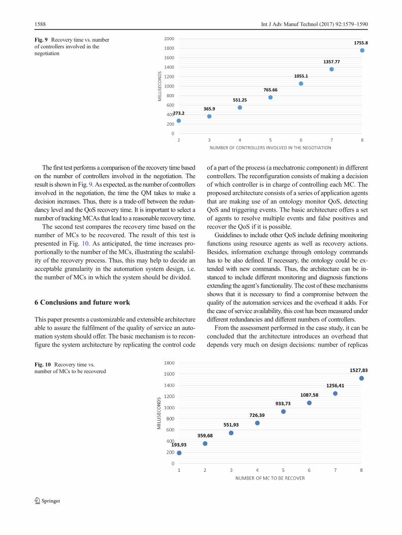
The first test performs a comparison of the recovery time basedon the number of controllers involved in the negotiation. Theresult is shown in Fig. 9.As expected, as the number of controllersinvolved in the negotiation, the time the QM takes to make adecision increases. Thus, there is a trade-off between the redun-dancy level and the QoS recovery time. It is important to select anumber of trackingMCAs that lead to a reasonable recovery time.
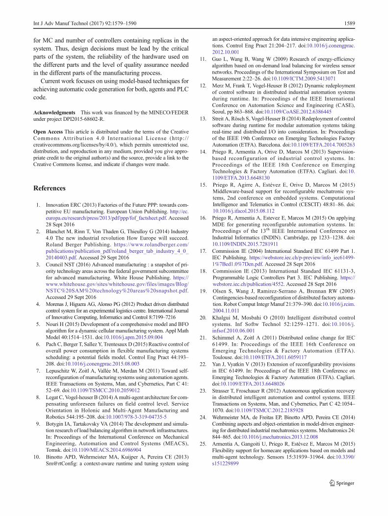
The second test compares the recovery time based on thenumber of MCs to be recovered. The result of this test ispresented in Fig. 10. As anticipated, the time increases pro-portionally to the number of the MCs, illustrating the scalabil-ity of the recovery process. Thus, this may help to decide anacceptable granularity in the automation system design, i.e.the number of MCs in which the system should be divided.
6 Conclusions and future work
This paper presents a customizable and extensible architectureable to assure the fulfilment of the quality of service an auto-mation system should offer. The basic mechanism is to recon-figure the system architecture by replicating the control code
of a part of the process (a mechatronic component) in differentcontrollers. The reconfiguration consists of making a decisionof which controller is in charge of controlling each MC. Theproposed architecture consists of a series of application agentsthat are making use of an ontology monitor QoS, detectingQoS and triggering events. The basic architecture offers a setof agents to resolve multiple events and false positives andrecover the QoS if it is possible.
Guidelines to include other QoS include defining monitoringfunctions using resource agents as well as recovery actions.Besides, information exchange through ontology commandshas to be also defined. If necessary, the ontology could be ex-tended with new commands. Thus, the architecture can be in-stanced to include different monitoring and diagnosis functionsextending the agent’s functionality. The cost of thesemechanismsshows that it is necessary to find a compromise between thequality of the automation services and the overhead it adds. Forthe case of service availability, this cost has been measured underdifferent redundancies and different numbers of controllers.
From the assessment performed in the case study, it can beconcluded that the architecture introduces an overhead thatdepends very much on design decisions: number of replicas
273.2365.9
551.25
765.66
1055.1
1357.77
1755.8
0
200
400
600
800
1000
1200
1400
1600
1800
2000
2 3 4 5 6 7 8
MIL
LISE
CON
DS
NUMBER OF CONTROLLERS INVOLVED IN THE NEGOTIATION
Fig. 9 Recovery time vs. numberof controllers involved in thenegotiation
Fig. 10 Recovery time vs.number of MCs to be recovered
1588 Int J Adv Manuf Technol (2017) 92:1579–1590
for MC and number of controllers containing replicas in thesystem. Thus, design decisions must be lead by the criticalparts of the system, the reliability of the hardware used onthe different parts and the level of quality assurance neededin the different parts of the manufacturing process.
Current work focuses on using model-based techniques forachieving automatic code generation for both, agents and PLCcode.
Acknowledgments This work was financed by the MINECO/FEDERunder project DPI2015-68602-R.
Open Access This article is distributed under the terms of the CreativeCommons At t r ibut ion 4 .0 In te rna t ional License (h t tp : / /creativecommons.org/licenses/by/4.0/), which permits unrestricted use,distribution, and reproduction in any medium, provided you give appro-priate credit to the original author(s) and the source, provide a link to theCreative Commons license, and indicate if changes were made.
References
1. Innovation ERC (2013) Factories of the Future PPP: towards com-petitive EU manufacturing. European Union Publishing. http://ec.europa.eu/research/press/2013/pdf/ppp/fof_factsheet.pdf. Accessed28 Sept 2016
2. Blanchet M, Rinn T, Von Thaden G, Thieulloy G (2014) Industry4.0 The new industrial revolution How Europe will succeed.Roland Berger Publishing. https://www.rolandberger.com/publications/publication_pdf/roland_berger_tab_industry_4_0_20140403.pdf. Accessed 29 Sept 2016
3. Council NST (2016) Advanced manufacturing : a snapshot of pri-ority technology areas across the federal government subcommitteefor advanced manufacturing. White House Publishing. https://www.whitehouse.gov/sites/whitehouse.gov/files/images/Blog/NSTC%20SAM%20technology%20areas%20snapshot.pdf.Accessed 29 Sept 2016
4. Morenas J, Higuera AG, Alonso PG (2012) Product driven distributedcontrol system for an experimental logistics centre. International Journalof Innovative Computing, Informatics and Control 8:7199–7216
5. Nouri H (2015) Development of a comprehensive model and BFOalgorithm for a dynamic cellular manufacturing system. Appl MathModel 40:1514–1531. doi:10.1016/j.apm.2015.09.004
6. Pach C, Berger T, Sallez Y, TrentesauxD (2015) Reactive control ofoverall power consumption in flexible manufacturing systemsscheduling: a potential fields model. Control Eng Pract 44:193–208. doi:10.1016/j.conengprac.2015.08.003
7. Lepuschitz W, Zoitl A, Vallée M, Merdan M (2011) Toward self-reconfiguration of manufacturing systems using automation agents.IEEE Transactions on Systems, Man, and Cybernetics, Part C 41:52–69. doi:10.1109/TSMCC.2010.2059012
8. Legat C, Vogel-heuser B (2014) Amulti-agent architecture for com-pensating unforeseen failures on field control level. ServiceOrientation in Holonic and Multi-Agent Manufacturing andRobotics 544:195–208. doi:10.1007/978-3-319-04735-5
9. Botygin IA, Tartakovsky VA (2014) The development and simula-tion research of load balancing algorithm in network infrastructures.In: Proceedings of the International Conference on MechanicalEngineering, Automation and Control Systems (MEACS),Tomsk. doi:10.1109/MEACS.2014.6986904
10. Binotto APD, Wehrmeister MA, Kuijper A, Pereira CE (2013)Sm@rtConfig: a context-aware runtime and tuning system using
an aspect-oriented approach for data intensive engineering applica-tions. Control Eng Pract 21:204–217. doi:10.1016/j.conengprac.2012.10.001
11. Guo L, Wang B, Wang W (2009) Research of energy-efficiencyalgorithm based on on-demand load balancing for wireless sensornetworks. Proceedings of the International Symposium on Test andMeasurement 2:22–26. doi:10.1109/ICTM.2009.5413071
12. Merz M, Frank T, Vogel-Heuser B (2012) Dynamic redeploymentof control software in distributed industrial automation systemsduring runtime. In: Proceedings of the IEEE InternationalConference on Automation Science and Engineering (CASE),Seoul, pp 863–868. doi:10.1109/CoASE.2012.6386445
13. Streit A, Rösch S, Vogel-Heuser B (2014) Redeployment of controlsoftware during runtime for modular automation systems takingreal-time and distributed I/O into consideration. In: Proceedingsof the IEEE 19th Conference on Emerging Technologies FactoryAutomation (ETFA). Barcelona. doi:10.1109/ETFA.2014.7005263
14. Priego R, Armentia A, Orive D, Marcos M (2013) Supervision-based reconfiguration of industrial control systems. In:Proceedings of the IEEE 18th Conference on EmergingTechnologies & Factory Automation (ETFA). Cagliari. doi:10.1109/ETFA.2013.6648130
15. Priego R, Agirre A, Estévez E, Orive D, Marcos M (2015)Middleware-based support for reconfigurable mechatronic sys-tems, 2nd conference on embedded systems. ComputationalIntelligence and Telematics in Control (CESCIT) 48:81–86. doi:10.1016/j.ifacol.2015.08.112
16. Priego R, Armentia A, Estevez E, Marcos M (2015) On applyingMDE for generating reconfigurable automation systems. In:Proceedings of the 13th IEEE International Conference onIndustrial Informatics (INDIN). Cambridge, pp 1233–1238. doi:10.1109/INDIN.2015.7281911
17. Commission IE (2004) International Standard IEC 61499 Part 1.IEC Publishing. https://webstore.iec.ch/p-preview/info_iec61499-1%7Bed1.0%7Den.pdf. Accessed 28 Sept 2016
18. Commission IE (2013) International Standard IEC 61131-3,Programmable Logic Controllers Part 3. IEC Publishing. https://webstore.iec.ch/publication/4552. Accessed 28 Sept 2016
19. Olsen S, Wang J, Ramirez-Serrano A, Brennan RW (2005)Contingencies-based reconfiguration of distributed factory automa-tion. Robot Comput Integr Manuf 21:379–390. doi:10.1016/j.rcim.2004.11.011
20. Khalgui M, Mosbahi O (2010) Intelligent distributed controlsystems. Inf Softw Technol 52:1259–1271. doi:10.1016/j.infsof.2010.06.001
21. Schimmel A, Zoitl A (2011) Distributed online change for IEC61499. In: Proceedings of the IEEE 16th Conference onEmerging Technologies & Factory Automation (ETFA).Toulouse. doi:10.1109/ETFA.2011.6059117
22. Yan J, Vyatkin V (2013) Extension of reconfigurability provisionsin IEC 61499. In: Proceedings of the IEEE 18th Conference onEmerging Technologies & Factory Automation (ETFA). Cagliari.doi:10.1109/ETFA.2013.6648026
23. Strasser T, Froschauer R (2012) Autonomous application recoveryin distributed intelligent automation and control systems. IEEETransactions on Systems, Man, and Cybernetics, Part C 42:1054–1070. doi:10.1109/TSMCC.2012.2185928
24. Wehrmeister MA, de Freitas EP, Binotto APD, Pereira CE (2014)Combining aspects and object-orientation in model-driven engineer-ing for distributed industrial mechatronics systems. Mechatronics 24:844–865. doi:10.1016/j.mechatronics.2013.12.008
25. Armentia A, Gangoiti U, Priego R, Estévez E, Marcos M (2015)Flexibility support for homecare applications based on models andmulti-agent technology. Sensors 15:31939–31964. doi:10.3390/s151229899
Int J Adv Manuf Technol (2017) 92:1579–1590 1589

26. Thramboulidis K (2005) Model integrated mechatronics—towardsa new paradigm in the development of manufacturing systems.IEEE Transactions on Industrial Informatics 1:54–61
27. Lüder A, Estévez E, Hundt L, Marcos M (2010) Automatic trans-formation of logic models within engineering of embeddedmechatronical units. Int J Adv Manuf Technol 54:1077–1089.doi:10.1007/s00170-010-3010-y
28. Bellifemine F, Poggi A, Rimassa G (2001) Developing multi-agentsystems with a FIPA-compliant agent framework. Software -Practice and Experience 31:103–128
29. Bellifemine F, Caire G, Poggi A, Rimassa G (2008) JADE: a soft-ware framework for developing multi-agent applications. Lessonslearned Information and Software Technology 50:10–21. doi:10.1016/j.infsof.2007.10.008
30. FIPA (2015) Standard FIPA Specifications. FIPA Publishing. http://www.fipa.org/repository/standardspecs.html. Accessed 7 Sept2015
1590 Int J Adv Manuf Technol (2017) 92:1579–1590


