Embed Size (px)
Citation preview
Copyright © 2014 by the American Institute of Aeronautics and Astronautics, Inc. The U.S. Government has a royalty-free license to exercise all rights under the copyright claimed herein for Governmental purposes. All other rights are reserved by the copyright owner.
1
Advancing Navigation, Timing, and Science with the Deep Space Atomic Clock
Todd A. Ely,1 Jill Seubert,2 Julia Bell3 Jet Propulsion Laboratory, California Institute of Technology, Pasadena, CA, 91109-8099
NASA’s Deep Space Atomic Clock mission is developing a small, highly stable mercury ion atomic clock with an Allan deviation of at most 1e-14 at one day, and with current estimates near 3e-15. This stability enables one-way radiometric tracking data with accuracy equivalent to and, in certain conditions, better than current two-way deep space tracking data; allowing a shift to a more efficient and flexible one-way deep space navigation architecture. DSAC-enabled one-way tracking will benefit navigation and radio science by increasing the quantity and quality of tracking data. Additionally, DSAC would be a key component to fully-autonomous onboard radio navigation useful for time-sensitive situations. Potential deep space applications of DSAC are presented, including orbit determination of a Mars orbiter and gravity science on a Europa flyby mission.
Nomenclature 𝐵! = downlink carrier loop bandwidth, c = speed of light, {Cnm,Snm} = static gravity field coefficients, f = signal frequency, F = solar plasma scaling factor on Doppler noise, G = transponding ratio, k2X = Love number 2X, µ = Europa gravitational constant, n = degree of spherical harmonic coefficient, 𝑁! = noise spectral density, 𝑃! = uplink carrier power, 𝜌! = downlink carrier loop SNR, Re = Europa radius, Rmantle
= Europa mantle radius, 𝜎 = spherical harmonic coefficient uncertainty, 𝜎! = SNR noise uncertainty, 𝜎! = plasma noise uncertainty, s = spherical harmonic coefficient scale factor, SEP = Sun-Earth-Probe angle, τ = Doppler integration time, T = dominant signal time scale, x = clock phase error,
1 DSAC Principal Investigator, Jet Propulsion Laboratory, California Institute of Technology, MS 301-121, 4800 Oak Grove Drive, Pasadena, CA, 91109-8099, AIAA Senior Member. 2 DSAC Investigation System Engineer, Jet Propulsion Laboratory, California Institute of Technology, MS 301-121, 4800 Oak Grove Drive, Pasadena, CA, 91109-8099, AIAA Member 3 DSAC Project Systems Engineer, Jet Propulsion Laboratory, California Institute of Technology, MS 301-490, 4800 Oak Grove Drive, Pasadena, CA, 91109-8099, AIAA Associate Fellow

Copyright © 2014 by the American Institute of Aeronautics and Astronautics, Inc. The U.S. Government has a royalty-free license to exercise all rights under the copyright claimed herein for Governmental purposes. All other rights are reserved by the copyright owner.
2
I. Introduction urrent deep space navigation depends primarily on ground-based atomic clocks for the formation of accurate two-way coherent radiometric measurements. Space-based clocks have lacked the high caliber accuracy and
stability necessary to navigate solely on one-way radiometric signals. The use of one-way tracking data is currently limited by the correlation between long-term frequency drift and orbital parameters. Recovering large clock bias and drift terms following long periods of no tracking yields significant degradations in orbit solution quality. The Deep Space Atomic Clock (DSAC) project is a NASA Technology Demonstration Mission (TDM) that will bridge the gap between ground and space clocks by validating the on-orbit performance of a small, low-mass mercury ion (199Hg+) atomic clock with long-term stability and accuracy on par with the clocks in use at the Deep Space Network (DSN). DSAC’s stability, as measured by its Allan Deviation (AD), is expected to be less than 3e-15 at one day, with a ground laboratory version of DSAC currently demonstrating an AD of approximately 1e-15 at one day. Such a small spacecraft clock error will enable one-way radiometric tracking data with accuracy equivalent to or better than current two-way tracking data, allowing a shift to a more efficient and flexible one-way deep space navigation architecture.
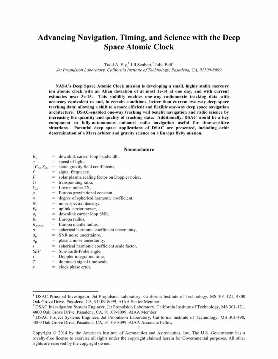
The project will advance the 199Hg+ atomic space clock technology from a Technology Readiness Level (TRL) 5 to TRL 7 by developing an advanced prototype, verifying its performance in space, and demonstrating its viability as navigation hardware. DSAC uses the property of mercury ions’ hyperfine transition frequency at ~40.5 GHz to effectively “steer” the frequency output of a quartz crystal oscillator to a near-constant value. It does this by stimulating mercury ion transitions confined in an electric field trap. Magnetic fields and shielding provide protection from external perturbations yielding a stable environment for measuring the transition very accurately while minimizing sensitivity to temperature and magnetic variations. Coupling this with the fact that the DSAC technology has almost no expendables enables its use for very long-duration space missions. More details of how the clock works can be found in Reference 1. The current best estimate (as of December 2013) of the DSAC Demonstration Unit’s (DU) size, weight, and average power are 29 cm x 26 cm x 23 cm, 16 kg, and 50 W, respectively. The preliminary configuration of the DU is shown in Figure 1. Another project objective is to identify improvements needed to readily fly DSAC on a future deep space mission or Global Navigation Satellite System (GNSS) application (in particular, DSAC elements amenable to reductions in size, weight, and power).
The DSAC mission will be a hosted payload onboard a Surrey Satellite Technology (SST-US) Orbital Test Bed (OTB) spacecraft, currently planned for an early-2016 launch into low Earth orbit (LEO). OTB is an Evolved Expendable Launch Vehicle (EELV) Secondary Payload Adapter (ESPA) compatible secondary spacecraft manifested on the US Air Force Space Technology Program II rocket, a Space Exploration Technology’s (SpaceX) Falcon Heavy. Once in LEO, DSAC’s space-based performance will be characterized via a year-long demonstration. The mission requirement is to validate the clock’s stability and drift with an AD of at most 2.0e-14 at one day while in orbit. This requirement is looser than the expected performance of the clock (as noted previously an AD ~ 3.0e-15) because of the presence of systematic errors in the measurement system; however, the performance of the validation system (like the clock itself) is expected to be better than this required level. The expected performance of the DSAC technology and mission has recently been documented in Reference 2.
In today’s two-way navigation architecture, the Deep Space Network (DSN) tracks a user spacecraft and then a ground-based team performs navigation. Relative to this, a one-way navigation architecture can deliver more data with better accuracy and is enabling for future autonomous radio navigation. Examples of how a one-way deep space tracking architecture with DSAC improves upon the existing two-way architecture include:
1. DSAC-based one-way radio tracking enables use of the existing DSN Multiple Spacecraft Per Aperture (MSPA) capability at destinations such as Mars for tracking. This can yield up to a factor of two increase in tracking relative to typical two-way schedules.
2. DSAC-based one-way radio tracking enables use of the existing DSN Ka-band downlink capability for radio tracking with almost an order of magnitude improvement in Doppler measurement precision over traditional X-band.
3. DSAC-based one-way radio tracking can utilize the full view period of an antenna whereas two-way tracking time is reduced from this period by the round trip light time.
4. DSAC is a radio science instrument (for both gravity and occultation science) that improves data precision, operational flexibility, and data quantity.
5. DSAC one-way radiometric tracking of a DSN uplink enables real-time autonomous navigation that, coupled with optical navigation, provides for a robust absolute and relative navigation system.
C
Copyright © 2014 by the American Institute of Aeronautics and Astronautics, Inc. The U.S. Government has a royalty-free license to exercise all rights under the copyright claimed herein for Governmental purposes. All other rights are reserved by the copyright owner.
3
These improvements in tracking can be applied to future missions already being contemplated. Clearly, the navigation and gravity science return of a future Mars orbiter would directly benefit from being able to use both the Ka-band and MSPA capabilities. Studies of Europa flyby mission gravity science have shown that uplink tracking with DSAC yields a robust method for recovering tidal gravity solutions, while minimizing impact to other science instruments and the flight system. For an aerobraking Mars orbiter, DSAC-enabled one-way tracking on an uplink coupled with an on-board guidance, navigation, and control (GNC) system makes it possible to conduct autonomous aerobraking operations and significantly reduce the ground support operations. Many mission concepts would benefit from using DSAC in improving navigation and radio-science and simplifying onboard timekeeping operations. In this paper, specific mission uses are discussed in depth (such as gravity science on a Europa flyby mission) as well as broader benefits for deep space navigation and radio science.
II. DSAC’s Utility for Tracking, Navigation, Science, and Timing Since DSAC would be a fundamental component to a spacecraft’s frequency and timing system and the
associated telecommunication infrastructure needed to support that spacecraft, it has broad benefits to navigation, timing, and radio science. A short discussion of these varied benefits for deep space applications follows.
A. Radiometric Tracking DSAC enables a shift to a one-way radiometric tracking architecture from the two-way architecture provided
today by the DSN. This has the potential to not only increase the amount of tracking data, but the quality of that data as well.
1. Increased Tracking Data Quantity and Asynchronous Operations The DSN can support multiple downlinks on a single antenna (Multiple Spacecraft Per Aperture, MSPA), but
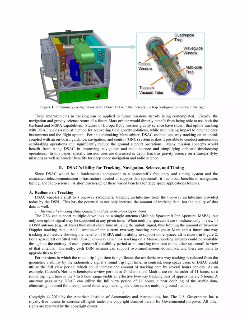
only one uplink signal may be supported at any given time. When multiple spacecraft are simultaneously in view of a DSN antenna (e.g., at Mars) they must share time utilizing the uplink signal, thus limiting the amount of two-way Doppler tracking data. An illustration of the current two-way tracking paradigm at Mars and a future one-way tracking architecture showing the benefits of MSPA and its ability to support more spacecraft is shown in Figure 2. For a spacecraft outfitted with DSAC, one-way downlink tracking on a Mars-supporting antenna could be available throughout the entirety of each spacecraft’s visibility period at no tracking time cost to the other spacecraft in view of that antenna. Currently, each DSN antenna can support two simultaneous downlinks, and there are plans to upgrade this to four.
For missions in which the round trip light time is significant, the available two-way tracking is reduced from the geometric visibility by the radiometric signal’s round trip light time. In contrast, deep space users of DSAC could utilize the full view period, which could increase the amount of tracking data by several hours per day. As an example, Cassini’s Northern hemisphere view periods at Goldstone and Madrid are on the order of 11 hours, so a round trip light time in the 4 to 5 hour range yields an effective two-way tracking pass of approximately 6 hours. A one-way pass using DSAC can utilize the full view period of 11 hours, a near doubling of the usable data, eliminating the need for a complicated three-way tracking operation across multiple ground stations.
Figure 1: Preliminary configuration of the DSAC DU with the mercury ion trap configuration shown to the right.
Copyright © 2014 by the American Institute of Aeronautics and Astronautics, Inc. The U.S. Government has a royalty-free license to exercise all rights under the copyright claimed herein for Governmental purposes. All other rights are reserved by the copyright owner.
4
When spacecraft are in the outer reaches of the solar system (such as Neptune, Uranus, and Pluto) light time delays become too large for collecting two-way measurements. In the current DSN configuration, tracking transitions to three-way operations where a DSN station will transmit a tracking signal that then returns and is received at a different DSN complex. Thus, a single two-way measurement requires two different antenna assets to complete the measurement. With DSAC, a one-way measurement would still require only the receiving antenna to form the measurement, thus freeing up the transmitting antenna to support another mission, and using the DSN infrastructure much more efficiently.
DSAC enables uplink tracking where the spacecraft, with a suitably configured radio, could formulate one-way range and Doppler measurements on board for immediate use (if real-time autonomous navigation is needed) or to telemeter back to Earth for more traditional ground-based navigation. In this later case, the downlink data for tracking is significantly reduced relative to modulating a downlink ranging signal. This frees significant bandwidth for science and engineering data return, again using the existing DSN tracking infrastructure more efficiently.
However, DSN support of one-way ranging on either an uplink or downlink would require changes to the range signal and calibration methods. DSAC is the enabling device to motivate these changes because the improved one-way data precision warrants providing this service. If engineered properly this type of service could provide uplink tracking to any and all users in view of the transmission signal (much like the broadcast service provided by GPS works today), thus further enhancing the capacity of the DSN without building new antennas.
2. Increased Tracking Data Quality Radio signal perturbations due to solar plasma can be a significant error source, particularly for spacecraft
traveling at low Sun-Earth-Probe (SEP) angles. In fact, X-band two-way Doppler measurement noise is dominated by the solar plasma induced noise even at moderate SEP angles. As the plasma disturbance is inversely proportional to the square of the transmission frequency, two-way Ka-band tracking at 32 GHz reduces the signal noise by a factor of approximately 15 compared to X-band tracking at 8.4 GHz (and reduces the noise by approximately 10 times compared to an X-band uplink/Ka-band downlink combination). While Ka-band uplink and downlink capabilities are available at the Goldstone DSN site, the Canberra and Madrid DSN sites can only support Ka-band on the downlink. A spacecraft utilizing DSAC could be tracked entirely on the Ka-band downlink regardless of the DSN site in view, effectively reducing the measurement noise by an order of magnitude.
With the solar plasma noise reduced at 32 GHz, the Ka-band Doppler measurement noise is dominated by the Earth’s tropospheric signal delay. The dry troposphere, constituting 80% of the total tropospheric delay, is typically well calibrated and can be removed as an error source. Water vapor radiometers (WVRs) may be utilized to remove up to 90% of the remaining wet troposphere error; however, WVRs cannot be used during periods of heavy cloud
Figure 2: Current and future tracking architectures using the DSN and MSPA.
Tomorrow’s 1-Way Radio Navigation Today’s 2-Way Radio Navigation
Copyright © 2014 by the American Institute of Aeronautics and Astronautics, Inc. The U.S. Government has a royalty-free license to exercise all rights under the copyright claimed herein for Governmental purposes. All other rights are reserved by the copyright owner.
5
cover and/or precipitation. Furthermore, the accuracy of GPS troposphere calibrations is larger than the wet troposphere noise itself on 60-second Ka-band Doppler data. Without calibration and removal of the wet troposphere error, the Ka-band Doppler noise may be increased by a factor of approximately 3 in the zenith direction. A DSAC-enabled one-way downlink signal could mitigate this signal degradation by allowing for any suitable Ka-band receiver (examples include ESA’s ground station at Malargue, Argentina, or JAXA’s station at Usuda, Japan) within view to receive the signal, avoiding weather conditions at a particular ground site.
Planetary investigations using radio occultations can benefit from DSAC as well. Today’s radio occultations rely on one-way tracking data derived from Ultra-stable oscillators (USOs). DSAC-enabled measurements are upwards of 10 times more accurate on the time scales relevant to atmosphere experiments (that is, the several minutes that a spacecraft radio signal to Earth rises and sets as it passes through the atmosphere of interest before being occulted by the planet). These benefits also apply to planetary ring occultation experiments.
3. Flight system impacts Another benefit of uplink one-way radiometric tracking is the signal power required to track is significantly
reduced as compared to a two-way link. This enables a spacecraft to utilize much lower gain antennas for tracking, which typically provide more hemispherical coverage. Additionally, most spacecraft employ low gain antennas in each discrete spacecraft-fixed direction (i.e., one on each X, Y, and Z oriented face) to provide full Earth coverage in the event of spacecraft faults or compromised communications. Coupling low power requirements with hemispherical low gain coverage implies one-way tracking with DSAC yields more actual tracking data in most operational situations (for instance, science orbits with constrained attitudes to support science instrument coverage) relative to two-way tracking that requires higher gain antennas (often gimbaled) to get equivalent tracking. A specific example of this benefit is presented in the context of the proposed Europa Clipper mission.
B. Navigation (including autonomous) and Radio Science The previous discussion focused on DSAC’s impact on the process and systems for collecting spacecraft
tracking data and on aspects of its quality. The implication of this on actual navigation and science operations and potential for new navigation paradigms is discussed now.
1. Ground-based Navigation Because DSAC stability and accuracy is on par with the DSN frequency and timing standards, DSAC-enabled
one-way radiometric data can be treated like two-way data in most deep space navigation applications. The one subtle difference with one-way data (vs. two-way) is the addition of an independent frequency reference. As a result there may exist small frequency biases between the transmitter and receiver that are not typically present in two-way data. The navigation filter can easily account for this by adding a frequency bias state to the estimation state. Analysis has shown that the addition of these states yields insignificant degradation to the navigation solution. In certain demanding navigation applications a tightly tuned stochastic process may need to be added to the filter to ensure the clock does not alias into other small stochastic processes already present in the filter (i.e., outgassing or solar pressure process noise). Example navigation solution results at various frequencies for a Mars orbiter are presented in the examples.
2. Autonomous Deep Space Navigation A one-way uplink received by a DSAC-enabled spacecraft with a properly configured and capable on-board
navigation system is able to self-navigate in deep space. Aspects of deep space navigation autonomy have been demonstrated using optical navigation with the Deep Space 1 (DS1) and Deep Impact missions.3,4 However, a complete implementation of a fully autonomous on-board navigation system would couple a DSAC-enabled one-way uplink (or forward link) radiometric tracking system with optical tracking from a camera system. This would combine the strengths of radio navigation for determining absolute location in deep space and in planetary orbits with the target relative navigation provided by the optical system. A combined one-way radiometric and optical autonomous navigation system would provide a powerful solution for robotic missions where ground-in-the-loop operations are infeasible (deep space encounters, planetary capture, real-time orbital operations, etc.), as well as supporting human exploration missions beyond low Earth orbit that require crewed operations without ground support.
3. Future tracking concepts with in-situ networks Much like GPS and the spacecraft atomic clocks that support that system, DSAC can form the time and
frequency basis for a future in-situ tracking network at another planet, such as Mars. Telecom and navigation orbiters at Mars and the Moon have been contemplated in the past, with initial plans and concepts developed for those sytems.5–8 Any tracking services provided by these systems would require an atomic clock to ensure stable and accurate frequency and time; DSAC provides sufficient performance in a small package to meet these needs. One-way tracking via an in-situ network combined with one-way tracking from the Earth (e.g. Figure 2) provides a

Copyright © 2014 by the American Institute of Aeronautics and Astronautics, Inc. The U.S. Government has a royalty-free license to exercise all rights under the copyright claimed herein for Governmental purposes. All other rights are reserved by the copyright owner.
6
robust mechanism to get timely tracking and navigation solutions to a planetary lander or orbiter for demanding real-time applications.
C. Timing and operational complexity, risk In addition to precise knowledge of the spacecraft location, precise knowledge of the time on-board the
spacecraft is necessary to successfully execute many deep space activities. For example, orbit insertion, planetary or small-body encounters, or entry-descent-and-landing all require precise timing to fire thrusters, point cameras, or initiate measurements. Hibernation during long-duration, quiescent cruise also requires a robust, stable on-board clock to reliably wake the spacecraft at the appropriate time. By reducing the inherent timing error below the threshold required for most deep space mission activities, a DSAC-enabled spacecraft eliminates much of the complexity of on-board-time-keeping, expands operational flexibility, and reduces operational risk.
A common approach for maintaining precise knowledge of the on-board time involves frequent measurements to correlate the on-board and ground times, requirements for each mission phase that drive operational complexity and staffing needs, ground-based processes for time-tagging the data, and mission operations procedures for distributing files and reprocessing received data. Monthly or even daily time correlation activities may be required for some events, depending on the mission requirements. Each time the process is executed, the mission is exposed to the risk of incorrect time-stamps in critical data, inconsistencies among teams that may all be required to provide inputs into a coordinated critical sequence, and, in the worst-case, loss of mission if activity times are not properly sequenced. In addition to the potential risks to critical events, the interpretation of science or engineering data may be influenced by updates or improvements to the ground’s knowledge of the time at which data was collected on board.
This traditional approach improves knowledge of spacecraft time on the ground but does not improve knowledge of absolute time on the spacecraft. Since one-way ranging and other autonomous navigation scenarios require knowledge of absolute time on-board, this ground-based approach is inadequate (without introducing additional processes to correlate the spacecraft with the ground that would introduce additional opportunities for risk). DSAC enables maintenance of a precision absolute time on-board that is sufficient for one-way ranging.
Time on a DSAC-enabled spacecraft is more stable than the (roughly) millisecond-level accuracy required for most mission critical events. This reduces the operational complexity and eliminates the need for some operational functions. Time correlation activities are not required beyond an initial calibration of the spacecraft clock with the ground-based clock which can be done on the ground, well before launch. Determination of the on-board clock is a natural by-product of the navigation analysis, instead of an input to the navigation process produced by a separate activity with ancillary, correlated data. The risk associated with updates to ground-based timing in series with the development of critical flight sequences is significantly reduced or eliminated.
III. Examples of Using DSAC In order to demonstrate some of the benefits DSAC provides to deep space applications, several examples are
presented which quantify the navigation and gravity science performance given DSAC-enabled one-way radiometric tracking as compared to traditional two-way tracking. The first is a comparison of the quality of X-band and Ka-band two-way and one-way Doppler tracking data. The second example examines the quality of trajectory reconstruction and static gravity field reconstruction for a Mars orbiter, similar to the Mars Reconnaissance Orbiter. This example highlights the solution improvement when the onboard frequency signal is generated via DSAC as compared to a standard space USO. A third example analyzes the performance of gravitational tide estimation for a Europa flyby mission operating in a low signal-to-noise (SNR) open-loop tracking configuration.
A. Doppler Data Quality The accuracy of a Doppler tracking signal directly impacts the quality of the estimation solution, and may lead to
the necessity to utilize specific telecommunication architectures in order to satisfy mission requirements. A detailed construction of the expected measurement noise on X-band and Ka-band 60-second Doppler tracking data is presented to illustrate the impact of DSAC’s onboard clock stochastic noise. In addition to the onboard clock, the Doppler data weight model includes the effects of finite SNR on the signal uplink and downlink, solar and ionospheric plasma variations, troposphere variations, ground clocks, spacecraft transponder, and ground antennas and electronics.
1. Finite SNR Noise The finite SNR noise 𝜎! introduced on the uplink and downlink of the carrier signal is a function of the speed of
light 𝑐, signal frequency 𝑓, Doppler integration time 𝜏, transponding ratio 𝐺, downlink carrier loop bandwidth 𝐵!,

Copyright © 2014 by the American Institute of Aeronautics and Astronautics, Inc. The U.S. Government has a royalty-free license to exercise all rights under the copyright claimed herein for Governmental purposes. All other rights are reserved by the copyright owner.
7
downlink carrier loop SNR 𝜌!, and uplink carrier power to noise spectral density ratio !!!!
found in Reference 9 and takes the form
ℴ! =!
! !!"#!!!+ !!!!
!!!!
(1)
The finite SNR noise model was evaluated for the Cassini cruise telecommunications system design as a representative deep space configuration.10 Note that the finite SNR noise is typically dominated by the downlink as the limited spacecraft transmit power results in a significantly lower downlink SNR as compared to the uplink signal generated by a 34 or 70 meter DSN antenna.
2. Plasma Noise Plasma noise, comprised of both solar plasma and ionosphere variations, is by far the dominant noise source for
X-band radio frequency communications (~8.4 GHz) and is a significant contributor to Ka-band noise (~32 GHz). Plasma noise stems from fluctuations of the refractive index of the space medium through which the signal passes, and is therefore a function of both distance from the Sun and the geometry of the signal line-of-sight relative to the Sun direction. Beyond 2.0 astronomical unit (AU), the 60-second plasma noise (𝜎!) is largely captured as a function of the Sun-Earth-Probe (SEP) angle, as empirically demonstrated for two-way X-band Doppler in Reference 11 as follows
𝜎! 60𝑠 = 𝑐 1.76 ∙ 10!!" sin 𝑆𝐸𝑃 !!.!" + 6.25 ∙ 10!!" sin 𝑆𝐸𝑃 !.!" , 0∘ ≤ 𝑆𝐸𝑃 ≤ 90∘ 𝜎! 60𝑠 = 𝑐 1.76 ∙ 10!!" + 6.25 ∙ 10!!" sin 𝑆𝐸𝑃 !.!" , 90∘ < 𝑆𝐸𝑃 ≤ 170∘ (2)
𝜎! 60𝑠 = 𝑐 1.27 ∙ 10!!" , 170∘ < 𝑆𝐸𝑃 ≤ 180∘ The plasma noise is therefore maximized when in solar conjunction and minimized in solar opposition. The
model referenced above is representative of the noise on a two-way X-band radio frequency link, and, assuming the uplink and downlink noise is uncorrelated and equivalent in strength, may be scaled by !
! to represent one-way X-
band plasma noise. Taking advantage of the inverse relationship between plasma noise and the square of the signal
frequency, the X-band noise is converted to Ka-band noise via scaling by !!!!"
!.
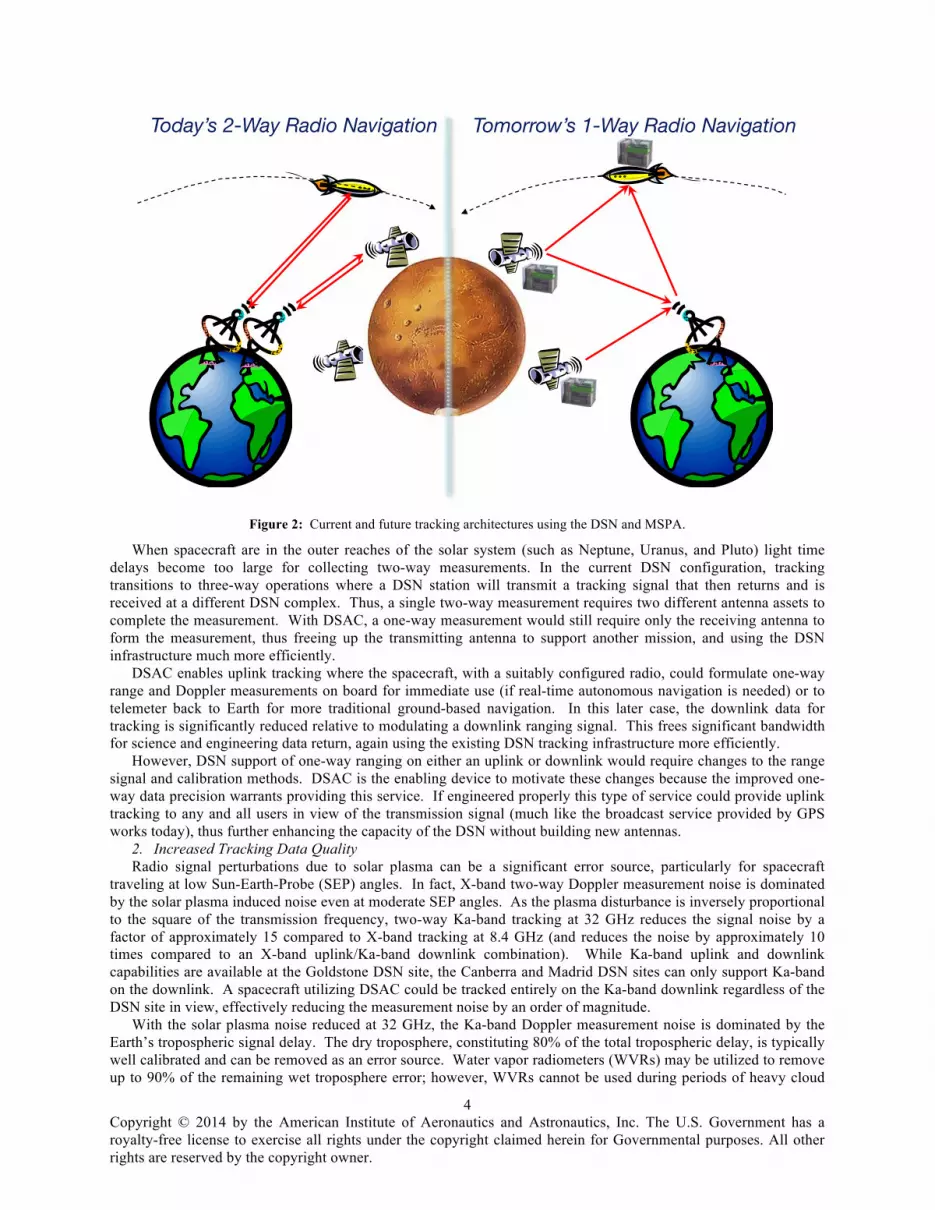
The model presented in Eq. (2) captures the short-term (60-second) stochastic behavior of the solar plasma noise. However, solar plasma noise has a 𝑓!!/! frequency power spectrum; traditional Kalman filters assume a 𝑓!! white noise frequency power spectrum.12 As such, the Kalman filter data must be handled appropriately to prevent unmodeled correlations in the Doppler data from aliasing into the estimation solution. Figure 3 illustrates the Allan
Figure 3: Allan deviation for example f -8/3 frequency power spectrum model and the associated observed and scaled white
frequency f -2 models.
100 101 102 103 104 105 10610ï16
10ï15
10ï14
10ï13
10ï12
10ï11
Alla
n D
evia
tion
Tau (sec)
Observed White Frequency NoiseExample fï8/3 ModelScaled White Frequency Noise
Copyright © 2014 by the American Institute of Aeronautics and Astronautics, Inc. The U.S. Government has a royalty-free license to exercise all rights under the copyright claimed herein for Governmental purposes. All other rights are reserved by the copyright owner.
8
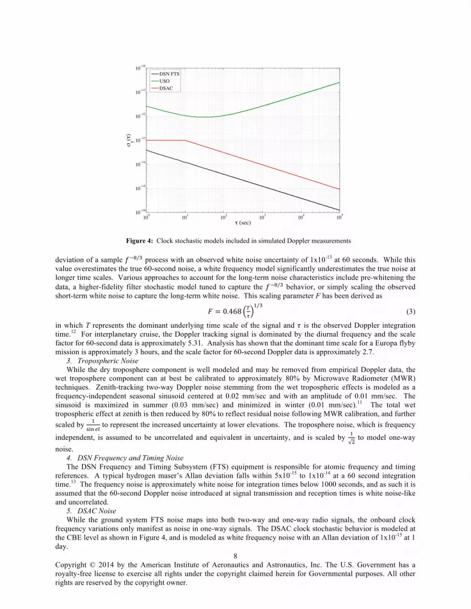
deviation of a sample 𝑓!!/! process with an observed white noise uncertainty of 1x10-13 at 60 seconds. While this value overestimates the true 60-second noise, a white frequency model significantly underestimates the true noise at longer time scales. Various approaches to account for the long-term noise characteristics include pre-whitening the data, a higher-fidelity filter stochastic model tuned to capture the 𝑓!!/! behavior, or simply scaling the observed short-term white noise to capture the long-term white noise. This scaling parameter F has been derived as
𝐹 = 0.468 !!
!/! (3)
in which T represents the dominant underlying time scale of the signal and 𝜏 is the observed Doppler integration time.12 For interplanetary cruise, the Doppler tracking signal is dominated by the diurnal frequency and the scale factor for 60-second data is approximately 5.31. Analysis has shown that the dominant time scale for a Europa flyby mission is approximately 3 hours, and the scale factor for 60-second Doppler data is approximately 2.7.
3. Tropospheric Noise While the dry troposphere component is well modeled and may be removed from empirical Doppler data, the
wet troposphere component can at best be calibrated to approximately 80% by Microwave Radiometer (MWR) techniques. Zenith-tracking two-way Doppler noise stemming from the wet tropospheric effects is modeled as a frequency-independent seasonal sinusoid centered at 0.02 mm/sec and with an amplitude of 0.01 mm/sec. The sinusoid is maximized in summer (0.03 mm/sec) and minimized in winter (0.01 mm/sec).11 The total wet tropospheric effect at zenith is then reduced by 80% to reflect residual noise following MWR calibration, and further scaled by !
!"# !" to represent the increased uncertainty at lower elevations. The troposphere noise, which is frequency
independent, is assumed to be uncorrelated and equivalent in uncertainty, and is scaled by !! to model one-way
noise. 4. DSN Frequency and Timing Noise The DSN Frequency and Timing Subsystem (FTS) equipment is responsible for atomic frequency and timing
references. A typical hydrogen maser’s Allan deviation falls within 5x10-15 to 1x10-14 at a 60 second integration time.13 The frequency noise is approximately white noise for integration times below 1000 seconds, and as such it is assumed that the 60-second Doppler noise introduced at signal transmission and reception times is white noise-like and uncorrelated.
5. DSAC Noise While the ground system FTS noise maps into both two-way and one-way radio signals, the onboard clock
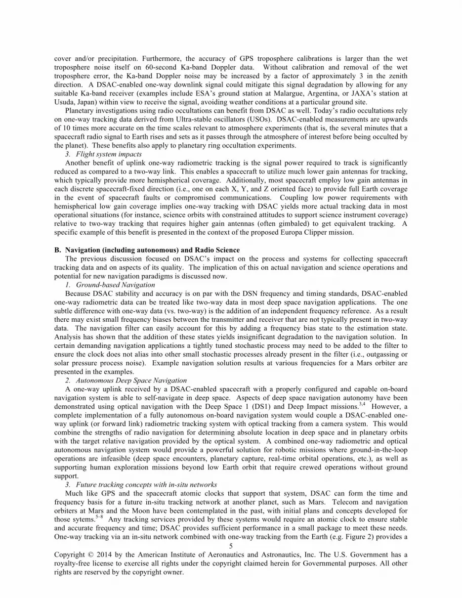
frequency variations only manifest as noise in one-way signals. The DSAC clock stochastic behavior is modeled at the CBE level as shown in Figure 4, and is modeled as white frequency noise with an Allan deviation of 1x10-15 at 1 day.
Figure 4: Clock stochastic models included in simulated Doppler measurements
100 101 102 103 104 10510ï16
10ï15
10ï14
10ï13
10ï12
10ï11
10ï10
o (sec)
my(o
)
DSN FTSUSODSAC
Copyright © 2014 by the American Institute of Aeronautics and Astronautics, Inc. The U.S. Government has a royalty-free license to exercise all rights under the copyright claimed herein for Governmental purposes. All other rights are reserved by the copyright owner.
9
6. Transponder, Ground Antenna, and Ground Electronics Noise The remaining Doppler noise sources are modeled in accordance with JPL operational experience. Transponder
noise, modeled after the Deep Space Transponder flown on Cassini, is modeled as white frequency noise with a 60-second Allan deviation of 1.8x10⁻¹⁴ for X-band communications and 5x10-15 for Ka-band communications.14 The transponder noise is included in the two-way Doppler data weight model due to the necessity for signal turn-around, and is appropriately omitted from the one-way Doppler data weight model. The noise introduced by thermal and mechanical deformations of the DSN ground antennas, respectively caused by time-varying thermal gradients and wind and gravitational loading, is modeled on a two-way signal as white frequency noise with an Allan deviation of 1.6x10⁻¹⁴ at 60 seconds. The contribution of DSN ground electronics noise, which excludes the FTS, has been empirically shown via end-to-end zero length two-way light time tests to be white noise in frequency space, with a 60-second Allan deviation of approximately 1.1x10-15.15 Both the ground antenna and ground electronics two-way noise are assumed to be uncorrelated at signal transmission and reception and are scaled by !
! to represent the one-
way Doppler uncertainty. A total 60-second Doppler data weight is then modeled as the root sum of squares of the individual noise
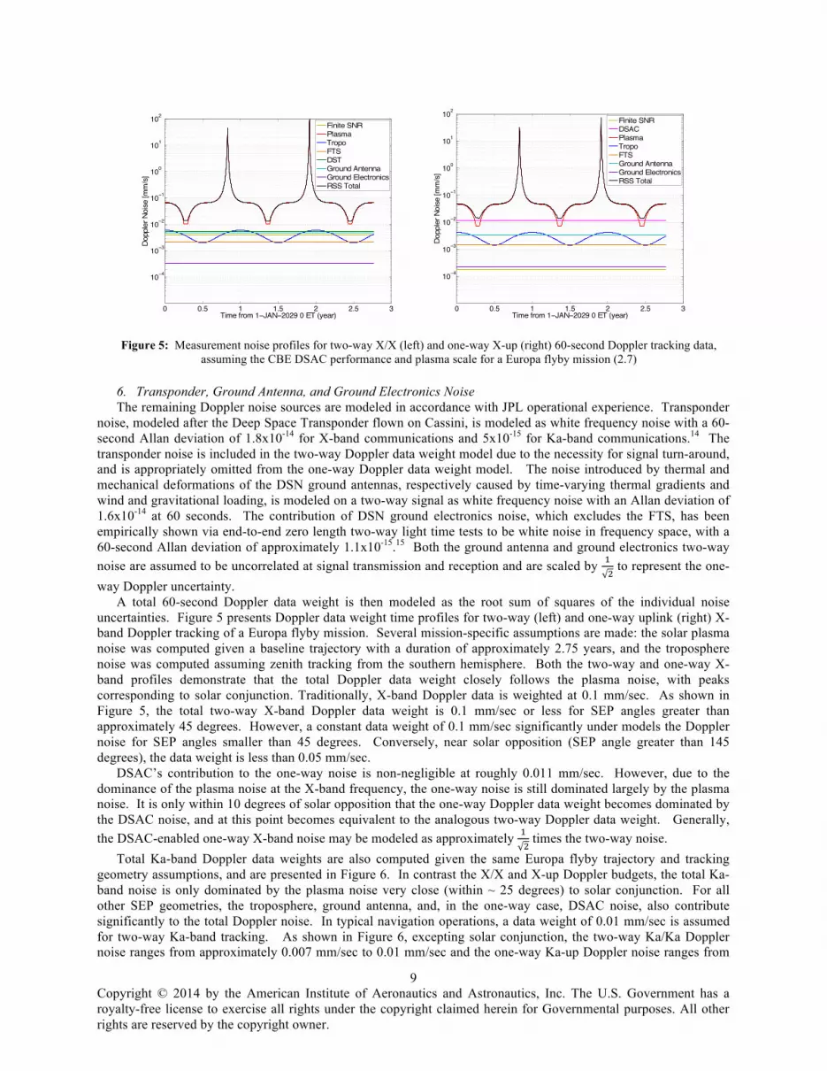
uncertainties. Figure 5 presents Doppler data weight time profiles for two-way (left) and one-way uplink (right) X-band Doppler tracking of a Europa flyby mission. Several mission-specific assumptions are made: the solar plasma noise was computed given a baseline trajectory with a duration of approximately 2.75 years, and the troposphere noise was computed assuming zenith tracking from the southern hemisphere. Both the two-way and one-way X-band profiles demonstrate that the total Doppler data weight closely follows the plasma noise, with peaks corresponding to solar conjunction. Traditionally, X-band Doppler data is weighted at 0.1 mm/sec. As shown in Figure 5, the total two-way X-band Doppler data weight is 0.1 mm/sec or less for SEP angles greater than approximately 45 degrees. However, a constant data weight of 0.1 mm/sec significantly under models the Doppler noise for SEP angles smaller than 45 degrees. Conversely, near solar opposition (SEP angle greater than 145 degrees), the data weight is less than 0.05 mm/sec.
DSAC’s contribution to the one-way noise is non-negligible at roughly 0.011 mm/sec. However, due to the dominance of the plasma noise at the X-band frequency, the one-way noise is still dominated largely by the plasma noise. It is only within 10 degrees of solar opposition that the one-way Doppler data weight becomes dominated by the DSAC noise, and at this point becomes equivalent to the analogous two-way Doppler data weight. Generally, the DSAC-enabled one-way X-band noise may be modeled as approximately !
! times the two-way noise.
Total Ka-band Doppler data weights are also computed given the same Europa flyby trajectory and tracking geometry assumptions, and are presented in Figure 6. In contrast the X/X and X-up Doppler budgets, the total Ka-band noise is only dominated by the plasma noise very close (within ~ 25 degrees) to solar conjunction. For all other SEP geometries, the troposphere, ground antenna, and, in the one-way case, DSAC noise, also contribute significantly to the total Doppler noise. In typical navigation operations, a data weight of 0.01 mm/sec is assumed for two-way Ka-band tracking. As shown in Figure 6, excepting solar conjunction, the two-way Ka/Ka Doppler noise ranges from approximately 0.007 mm/sec to 0.01 mm/sec and the one-way Ka-up Doppler noise ranges from
Figure 5: Measurement noise profiles for two-way X/X (left) and one-way X-up (right) 60-second Doppler tracking data,
assuming the CBE DSAC performance and plasma scale for a Europa flyby mission (2.7)
0 0.5 1 1.5 2 2.5 3
10−4
10−3
10−2
10−1
100
101
102
Time from 1−JAN−2029 0 ET (year)
Dop
pler
Noi
se [m
m/s
]
Finite SNRPlasmaTropoFTSDSTGround AntennaGround ElectronicsRSS Total
0 0.5 1 1.5 2 2.5 3
10−4
10−3
10−2
10−1
100
101
102
Time from 1−JAN−2029 0 ET (year)
Dop
pler
Noi
se [m
m/s
]
Finite SNRDSACPlasmaTropoFTSGround AntennaGround ElectronicsRSS Total

Copyright © 2014 by the American Institute of Aeronautics and Astronautics, Inc. The U.S. Government has a royalty-free license to exercise all rights under the copyright claimed herein for Governmental purposes. All other rights are reserved by the copyright owner.
10
approximately 0.012 mm/sec to 0.014 mm/sec. While Figure 6 shows that the one-way Ka-up Doppler noise is dominated by the DSAC stochastic clock noise, the resulting signal degradation is roughly equivalent to the increased plasma, troposphere, and ground antenna noise stemming from the two-way signal’s round-trip journey. In general, the DSAC-enabled one-way Doppler tracking data is shown to be as good as (Ka-band) or better than (X-band) its equivalent two-way counterpart.
B. Mars Orbiter and Radio Science: MSPA and Ka-band Tracking The target of over 40 missions and currently home to several orbiters, landers, and rovers, Mars continues to be a
planet of great interest. Currently, two spacecraft are en route to Mars (the Indian Space Research Organization’s Mangalyaan orbiter and NASA’s Mars Atmosphere and Volatile Evolution orbiter, MAVEN), and undoubtedly more will follow. Due to the relatively high density of Martian assets, a Mars orbiter scenario is utilized to quantify the benefits of exploiting the DSN’s Multiple Spacecraft Per Aperture (MSPA) and Ka-band downlink tracking capabilities.
The scenario is configured to mimic Mars Reconnaissance Orbiter (MRO) operational navigation and gravity field reconstruction.16,17 The simulated Mars orbiter is placed in a near-polar, sun-synchronous orbit with a 3649 km semi-major axis and eccentricity of 0.013. The initial state was propagated for 41 hours including the dynamical effects of solar pressure, Mars atmosphere, a 30x30 spherical harmonic Mars gravity field, and third body gravity for the sun, moon, and planets. The orbital dynamics model included a 10% random bias on the solar pressure scale factor and a 20% per-pass white noise stochastic process added to the nominal Martian atmospheric density. The resulting truth trajectory spans 30-APR-2012 0:0:0 ET to 01-MAY-2012 17:0:0 ET, which is consistent with a typical operational fit span.
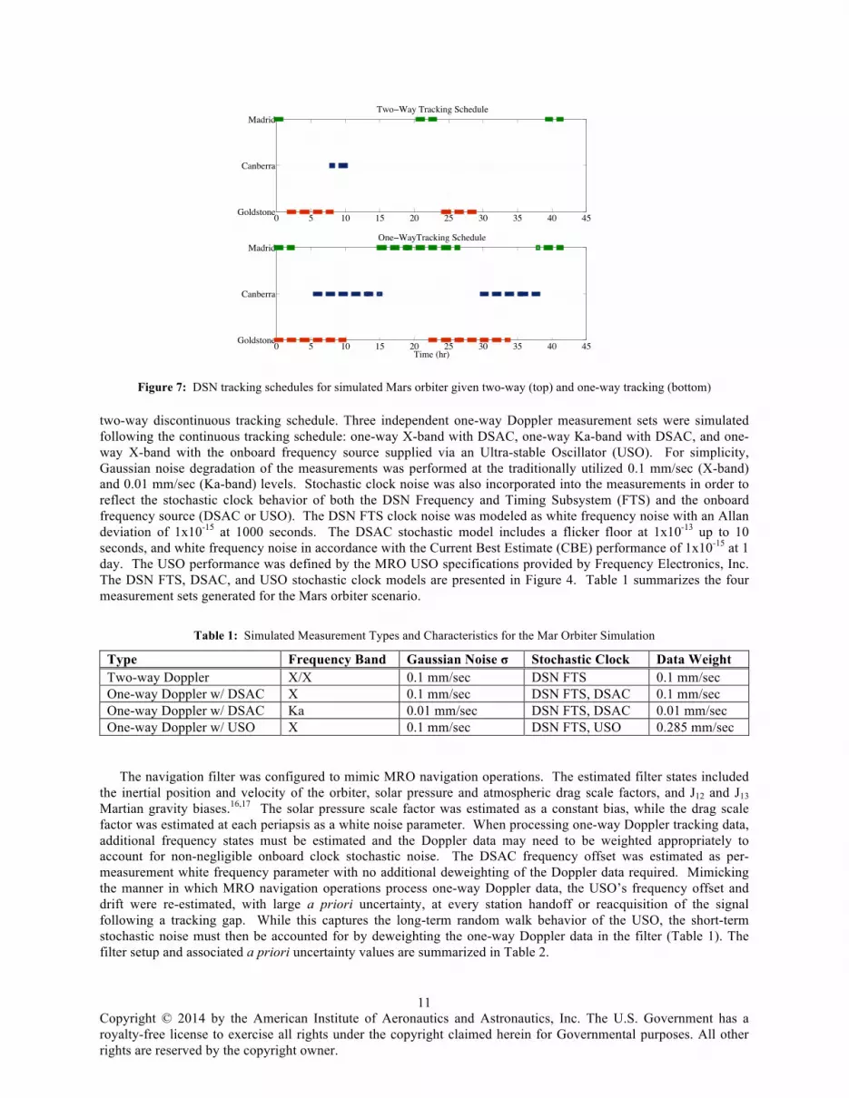
Traditionally, a Mars orbiter suffers two-way tracking gaps when the DSN is committed to tracking other spacecraft; a statistical assessment of MRO and Odyssey two-way tracking schedules over a three-month period revealed that the average gap is 3 to 5 hours in duration, occurring several times per day. However, both spacecraft infrequently experience lengthy tracking gaps, approximately 8 to 10 hours in duration, a few times each month. It is anticipated that the tracking gap duration and frequency will increase once MAVEN arrives in late 2014. Figure 7 (top) presents a typical DSN tracking schedule of a Mars orbiter, including a 10 degree elevation mask. While the spacecraft is always geometrically visible to at least one DSN ground antenna, 10 hour tracking gaps have been inserted to represent times during which the DSN is tracking other assets.
It is reasonable to assume that at any time at least one antenna is pointed toward bodies hosting multiple spacecraft, such as Mars or the Moon. For this case, the DSN’s MSPA capability may be exploited in a downlink-capacity; though an antenna may only perform two-way communications with one spacecraft at a time, the capability exists to receive multiple downlink signals simultaneously. In this manner, one-way downlink-only tracking data can be available continuously. This one-way continuous tracking configuration is illustrated in Figure 7 (bottom).
Doppler measurements were generated from the truth trajectory in accordance with the two-way and one-way DSN tracking schedules shown in Figure 7. Two-way X-band Doppler measurements were generated following the
Figure 6: Measurement noise profiles for two-way Ka/Ka (left) and one-way Ka-up (right) 60-second Doppler tracking data,
assuming the CBE DSAC performance and plasma scale for a Europa flyby mission (2.7)
0 0.5 1 1.5 2 2.5 3
10−4
10−3
10−2
10−1
100
101
102
Time from 1−JAN−2029 0 ET (year)
Dop
pler
Noi
se [m
m/s
]
Finite SNRPlasmaTropoFTSDSTGround AntennaGround ElectronicsRSS Total
0 0.5 1 1.5 2 2.5 3
10−4
10−3
10−2
10−1
100
101
102
Time from 1−JAN−2029 0 ET (year)
Dop
pler
Noi
se [m
m/s
]
Finite SNRDSACPlasmaTropoFTSGround AntennaGround ElectronicsRSS Total
Copyright © 2014 by the American Institute of Aeronautics and Astronautics, Inc. The U.S. Government has a royalty-free license to exercise all rights under the copyright claimed herein for Governmental purposes. All other rights are reserved by the copyright owner.
11
two-way discontinuous tracking schedule. Three independent one-way Doppler measurement sets were simulated following the continuous tracking schedule: one-way X-band with DSAC, one-way Ka-band with DSAC, and one-way X-band with the onboard frequency source supplied via an Ultra-stable Oscillator (USO). For simplicity, Gaussian noise degradation of the measurements was performed at the traditionally utilized 0.1 mm/sec (X-band) and 0.01 mm/sec (Ka-band) levels. Stochastic clock noise was also incorporated into the measurements in order to reflect the stochastic clock behavior of both the DSN Frequency and Timing Subsystem (FTS) and the onboard frequency source (DSAC or USO). The DSN FTS clock noise was modeled as white frequency noise with an Allan deviation of 1x10-15 at 1000 seconds. The DSAC stochastic model includes a flicker floor at 1x10-13 up to 10 seconds, and white frequency noise in accordance with the Current Best Estimate (CBE) performance of 1x10-15 at 1 day. The USO performance was defined by the MRO USO specifications provided by Frequency Electronics, Inc. The DSN FTS, DSAC, and USO stochastic clock models are presented in Figure 4. Table 1 summarizes the four measurement sets generated for the Mars orbiter scenario.
Table 1: Simulated Measurement Types and Characteristics for the Mar Orbiter Simulation
Type Frequency Band Gaussian Noise σ Stochastic Clock Data Weight Two-way Doppler X/X 0.1 mm/sec DSN FTS 0.1 mm/sec One-way Doppler w/ DSAC X 0.1 mm/sec DSN FTS, DSAC 0.1 mm/sec One-way Doppler w/ DSAC Ka 0.01 mm/sec DSN FTS, DSAC 0.01 mm/sec One-way Doppler w/ USO X 0.1 mm/sec DSN FTS, USO 0.285 mm/sec
The navigation filter was configured to mimic MRO navigation operations. The estimated filter states included the inertial position and velocity of the orbiter, solar pressure and atmospheric drag scale factors, and J12 and J13 Martian gravity biases.16,17 The solar pressure scale factor was estimated as a constant bias, while the drag scale factor was estimated at each periapsis as a white noise parameter. When processing one-way Doppler tracking data, additional frequency states must be estimated and the Doppler data may need to be weighted appropriately to account for non-negligible onboard clock stochastic noise. The DSAC frequency offset was estimated as per-measurement white frequency parameter with no additional deweighting of the Doppler data required. Mimicking the manner in which MRO navigation operations process one-way Doppler data, the USO’s frequency offset and drift were re-estimated, with large a priori uncertainty, at every station handoff or reacquisition of the signal following a tracking gap. While this captures the long-term random walk behavior of the USO, the short-term stochastic noise must then be accounted for by deweighting the one-way Doppler data in the filter (Table 1). The filter setup and associated a priori uncertainty values are summarized in Table 2.
Figure 7: DSN tracking schedules for simulated Mars orbiter given two-way (top) and one-way tracking (bottom)
0 5 10 15 20 25 30 35 40 45Goldstone
Canberra
MadridTwoïWay Tracking Schedule
0 5 10 15 20 25 30 35 40 45Goldstone
Canberra
Madrid
Time (hr)
OneïWayTracking Schedule
Copyright © 2014 by the American Institute of Aeronautics and Astronautics, Inc. The U.S. Government has a royalty-free license to exercise all rights under the copyright claimed herein for Governmental purposes. All other rights are reserved by the copyright owner.
12
Table 2: Mars Orbiter Navigation Filter Configuration
Estimated Parameter Type A Priori Uncertainty Position (EME2000) Dynamic 100 km Velocity (EME2000) Dynamic 10 m/sec Solar Pressure Scale Bias 10% of nominal (1.0) Drag Scale Stochastic 20% of nominal (1.0) Mars J12, J13 Bias 1x10⁻⁹ Frequency Offset (DSAC) Stochastic X-band: 0.3 mHz
Ka-band: 1.2 mHz Frequency Offset (USO) Stochastic 10 Hz Frequency Drift (USO) Stochastic 1x10⁻⁶ Hz/sec
Each of the four Doppler data sets was processed independently with the appropriate filter setup. The resulting
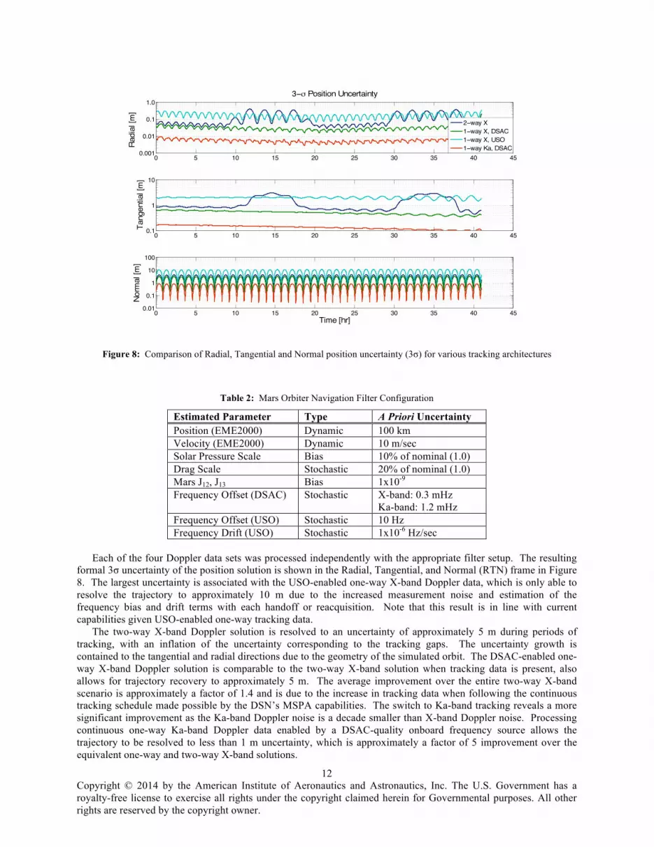
formal 3σ uncertainty of the position solution is shown in the Radial, Tangential, and Normal (RTN) frame in Figure 8. The largest uncertainty is associated with the USO-enabled one-way X-band Doppler data, which is only able to resolve the trajectory to approximately 10 m due to the increased measurement noise and estimation of the frequency bias and drift terms with each handoff or reacquisition. Note that this result is in line with current capabilities given USO-enabled one-way tracking data.
The two-way X-band Doppler solution is resolved to an uncertainty of approximately 5 m during periods of tracking, with an inflation of the uncertainty corresponding to the tracking gaps. The uncertainty growth is contained to the tangential and radial directions due to the geometry of the simulated orbit. The DSAC-enabled one-way X-band Doppler solution is comparable to the two-way X-band solution when tracking data is present, also allows for trajectory recovery to approximately 5 m. The average improvement over the entire two-way X-band scenario is approximately a factor of 1.4 and is due to the increase in tracking data when following the continuous tracking schedule made possible by the DSN’s MSPA capabilities. The switch to Ka-band tracking reveals a more significant improvement as the Ka-band Doppler noise is a decade smaller than X-band Doppler noise. Processing continuous one-way Ka-band Doppler data enabled by a DSAC-quality onboard frequency source allows the trajectory to be resolved to less than 1 m uncertainty, which is approximately a factor of 5 improvement over the equivalent one-way and two-way X-band solutions.
Figure 8: Comparison of Radial, Tangential and Normal position uncertainty (3σ) for various tracking architectures
0 5 10 15 20 25 30 35 40 450.001
0.01
0.1
1.0
Radi
al [m
]
3−m Position Uncertainty
2−way X1−way X, DSAC1−way X, USO1−way Ka, DSAC
0 5 10 15 20 25 30 35 40 450.1
1
10
Tang
entia
l [m
]
0 5 10 15 20 25 30 35 40 450.01
0.1
1
10
100
Norm
al [m
]
Time [hr]
Copyright © 2014 by the American Institute of Aeronautics and Astronautics, Inc. The U.S. Government has a royalty-free license to exercise all rights under the copyright claimed herein for Governmental purposes. All other rights are reserved by the copyright owner.
13
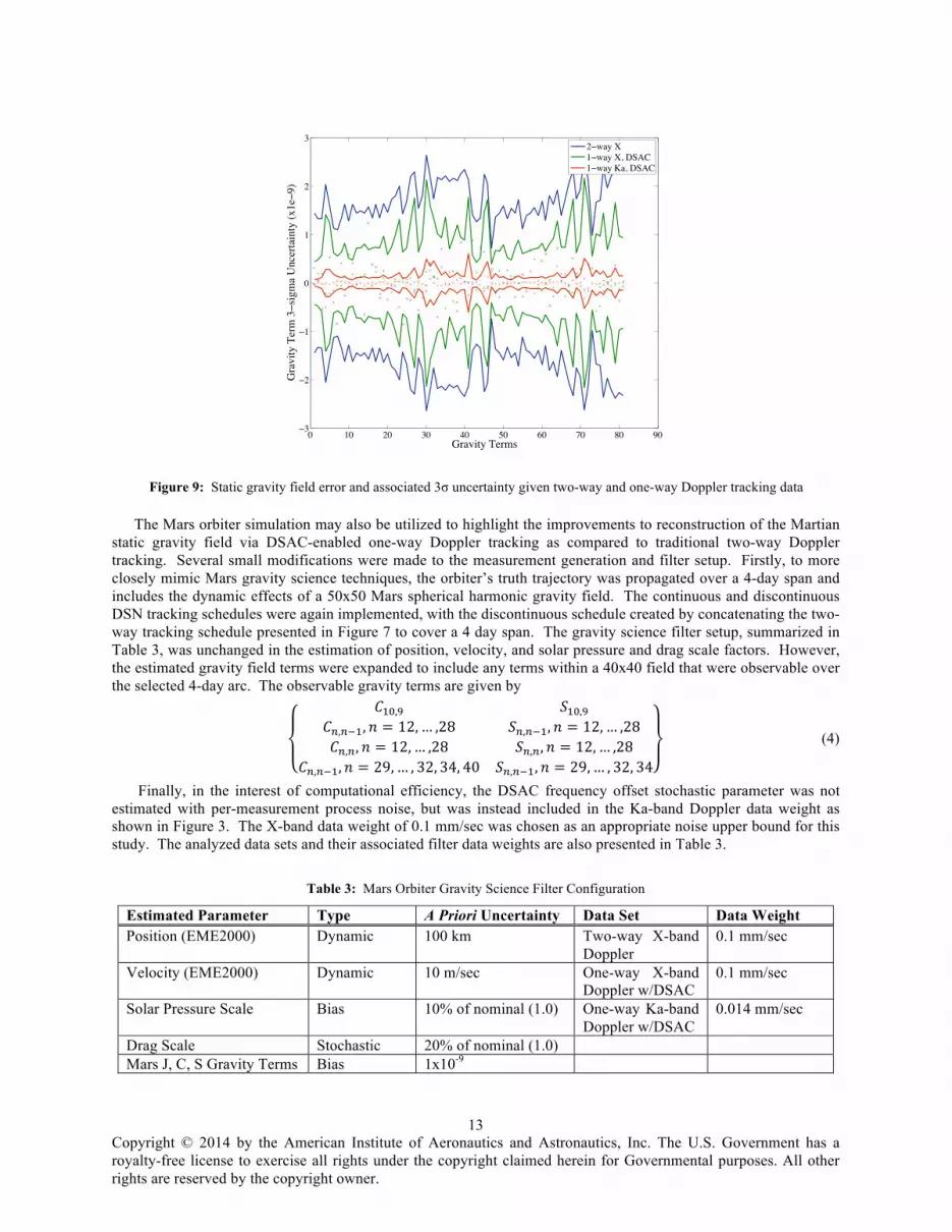
The Mars orbiter simulation may also be utilized to highlight the improvements to reconstruction of the Martian static gravity field via DSAC-enabled one-way Doppler tracking as compared to traditional two-way Doppler tracking. Several small modifications were made to the measurement generation and filter setup. Firstly, to more closely mimic Mars gravity science techniques, the orbiter’s truth trajectory was propagated over a 4-day span and includes the dynamic effects of a 50x50 Mars spherical harmonic gravity field. The continuous and discontinuous DSN tracking schedules were again implemented, with the discontinuous schedule created by concatenating the two-way tracking schedule presented in Figure 7 to cover a 4 day span. The gravity science filter setup, summarized in Table 3, was unchanged in the estimation of position, velocity, and solar pressure and drag scale factors. However, the estimated gravity field terms were expanded to include any terms within a 40x40 field that were observable over the selected 4-day arc. The observable gravity terms are given by
𝐶!",! 𝑆!",!𝐶!,!!!, 𝑛 = 12,… ,28 𝑆!,!!!, 𝑛 = 12,… ,28𝐶!,!, 𝑛 = 12,… ,28
𝐶!,!!!, 𝑛 = 29,… , 32, 34, 40𝑆!,!, 𝑛 = 12,… ,28
𝑆!,!!!, 𝑛 = 29,… , 32, 34
(4)
Finally, in the interest of computational efficiency, the DSAC frequency offset stochastic parameter was not estimated with per-measurement process noise, but was instead included in the Ka-band Doppler data weight as shown in Figure 3. The X-band data weight of 0.1 mm/sec was chosen as an appropriate noise upper bound for this study. The analyzed data sets and their associated filter data weights are also presented in Table 3.
Table 3: Mars Orbiter Gravity Science Filter Configuration
Estimated Parameter Type A Priori Uncertainty Data Set Data Weight Position (EME2000) Dynamic 100 km Two-way X-band
Doppler 0.1 mm/sec
Velocity (EME2000) Dynamic 10 m/sec One-way X-band Doppler w/DSAC
0.1 mm/sec
Solar Pressure Scale Bias 10% of nominal (1.0) One-way Ka-band Doppler w/DSAC
0.014 mm/sec
Drag Scale Stochastic 20% of nominal (1.0) Mars J, C, S Gravity Terms Bias 1x10⁻⁹
Figure 9: Static gravity field error and associated 3σ uncertainty given two-way and one-way Doppler tracking data
0 10 20 30 40 50 60 70 80 90ï3
ï2
ï1
0
1
2
3
Gravity Terms
Gra
vity
Ter
m 3ïs
igm
a U
ncer
tain
ty (x
1eï9
)
2ïway X1ïway X, DSAC1ïway Ka, DSAC
Copyright © 2014 by the American Institute of Aeronautics and Astronautics, Inc. The U.S. Government has a royalty-free license to exercise all rights under the copyright claimed herein for Governmental purposes. All other rights are reserved by the copyright owner.
14
Figure 9 presents the formal uncertainty (3σ) of the estimated Mars gravity terms for each of the independently processed Doppler data sets. For brevity, the estimated gravity terms shown in Eq. (4) have simply been numbered 1 through 81. The DSAC-enabled one-way Doppler solutions offer a significant improvement in gravity solution quality compared to the two-way X-band Doppler solution; on average the solution uncertainty is decreased by factors of ~ 2 and ~ 12 given the X-band and Ka-band one-way Doppler data, respectively. Though DSAC-enabled one-way X-band Doppler data was weighted equivalently to two-way X-band Doppler data for this analysis, the one-way configuration may take advantage of the continuous tracking available through MSPA.
As demonstrated, both Mars orbiter trajectory and gravity field reconstruction can greatly benefit from the tracking enhancements DSAC provides, including MSPA downlink tracking and Ka-band operations. Both of these capabilities are only currently available across all DSN assets in a downlink configuration, limiting their applicability solely to a one-way tracking architecture.
C. Europa Clipper and Gravity Science: Low SNR Tracking in Deep Space From the first images of the Jovian moon Europa, returned by the Pioneer spacecraft, to the Galileo spacecraft’s
measurements of an induced magnetic field, to the Hubble spacecraft’s recent detection of water plumes near the south pole, evidence that has been mounting suggests that a liquid water ocean exists beneath Europa’s icy crust. In order to investigate Europa’s habitability and prepare for follow-on exploratory missions, a potential Europa mission would, among other objectives, definitively confirm the existence of and perhaps characterize this subsurface ocean. Confirmation that a liquid ocean does exist is possible through reconstruction of the Europa gravitational tides. Europa is tidally locked to Jupiter and exhibits a strong longitudinal gravity field profile; measuring the time-varying gravitational tides, dominated by the second-degree harmonics, could differentiate between a solid and liquid body. Recovering the second degree, second order gravitational tide Love number k22 to an uncertainty less than 0.05 will confirm the existence of a liquid ocean.18
A spacecraft in orbit about Europa could return enough radiometric tracking data to resolve the k22 parameter to an order of magnitude greater than the stated requirement. In contrast, a spacecraft in orbit about Jupiter, performing periodic flybys of Europa, suffers limited useful tracking data as the gravitational tide sensitivity is confined to roughly an hour about Europan periapsis. A baseline Europa flyby trajectory will perform 45 flybys over a time period of approximately 2.75 years from February 2029 to October 2031.19 This baseline trajectory has been designed in part for gravity science return, with a series of flybys (E17 through E24) targeting a specific longitude and latitude space of increased sensitivity to the targeted tidal effect. Gravity information extracted from the X-band Doppler tracking available over subsequent flybys can be stitched together to provide a global gravity solution.
For deep space communications across large distances such as those encountered throughout the Europa flyby trajectory, it can become difficult to provide a sufficiently large signal-to-noise ratio (SNR) for closed-loop two-way tracking. Though the DSN is capable of transmitting a signal with very large transmit power, the spacecraft is often power-limited and requires significant spacecraft antenna gain on the downlink for the DSN to closed-loop track the returned signal. For this reason, a high gain antenna (HGA) is traditionally used for Doppler tracking of deep space craft. However, in certain configurations HGA access may not be available for Doppler tracking; for example, the spacecraft attitude required to accommodate primary science payloads during close approach may exclude the Earth line-or-sight from a HGA’s field of view (FOV). In such a scenario, it is necessary to explore open-loop tracking of the Doppler carrier signal, which requires a lesser spacecraft antenna gain and may thus be facilitated via medium gain antennas, such as fan beams, or low gain antennas (LGAs).
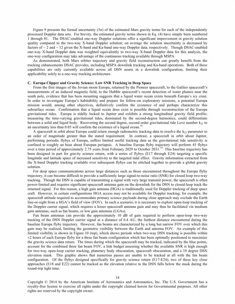
Fan beam antennas can provide the approximately 10 dB of gain required to perform open-loop two-way tracking of the DSN Doppler carrier signal at a distance of 6.4 AU, the furthest distance encountered during the baseline Europa flyby trajectory. However, fan beams are characterized by a long but narrow FOV over which this gain may be realized, limiting the geometric visibility between the Earth and antenna FOV. An example of this limited visibility is shown in Figure 10 (top), which shows periods when two-way DSN tracking is possible within ±2 hours of each Europa flyby for a three fan beam configuration which has been optimally positioned to maximize the gravity science data return. The times during which the spacecraft may be tracked, indicated by the blue points, account for the combined three fan beam FOV, a link budget assessing whether the available SNR is high enough for two-way open-loop carrier tracking, planetary body obscuration, spacecraft obscuration, and a 10 degree DSN elevation mask. This graphic shows that numerous passes are unable to be tracked at all with the fan beam configuration. Of the flybys designed specifically for gravity science return (E17-E24), two of these key close approaches (E18 and E22) cannot be tracked as the elevation relative to the DSN falls below the mask during the round-trip light time.
Copyright © 2014 by the American Institute of Aeronautics and Astronautics, Inc. The U.S. Government has a royalty-free license to exercise all rights under the copyright claimed herein for Governmental purposes. All other rights are reserved by the copyright owner.
15
In contrast to the limited FOV of medium gain fan beam antennas, LGAs producing 5-6 dB of gain exhibit hemispheric FOV coverage and are typically baselined into spacecraft design as a means of communication in the event of spacecraft tumble. This low gain is insufficient for two-way open-loop tracking. However, at 6.4 AU only 5.5 dB is required to perform one-way open or closed-loop carrier signal tracking on the uplink. In this uplink-only configuration, the carrier signal collected during flybys could be stored onboard for future downlink to Earth during less critical periods. Open-loop tracking requires at least 10 dB-Hz power-to-noise, and closed-loop tracking requires at least 20 dB-Hz. Though the pointing loss increases with off-boresight pointing, sufficient SNR may be realized for significant large off-boresight angles. Based on MRO’s LGA specifications, it was assumed that closed-loop tracking is realizable for up to 26 degrees off-boresight (corresponding to ~ 2 dB pointing loss), and open-loop tracking is possible up to an angle of 70 degrees (~ 12 dB pointing loss). Assuming a 70 degree half-angle conic FOV, LGAs placed along the velocity, anti-velocity, and zenith (relative to Europa) spacecraft faces can provide near-complete tracking coverage of the 45 Europa flybys (Figure 10, bottom). The access intervals shown in Figure 10 (bottom) account for the combined three LGA FOV, link budget for uplink-only open-loop carrier tracking, planetary body obscuration, and a 10 degree DSN elevation mask. It is assumed that the LGAs may be positioned such that spacecraft obscuration is negligible.
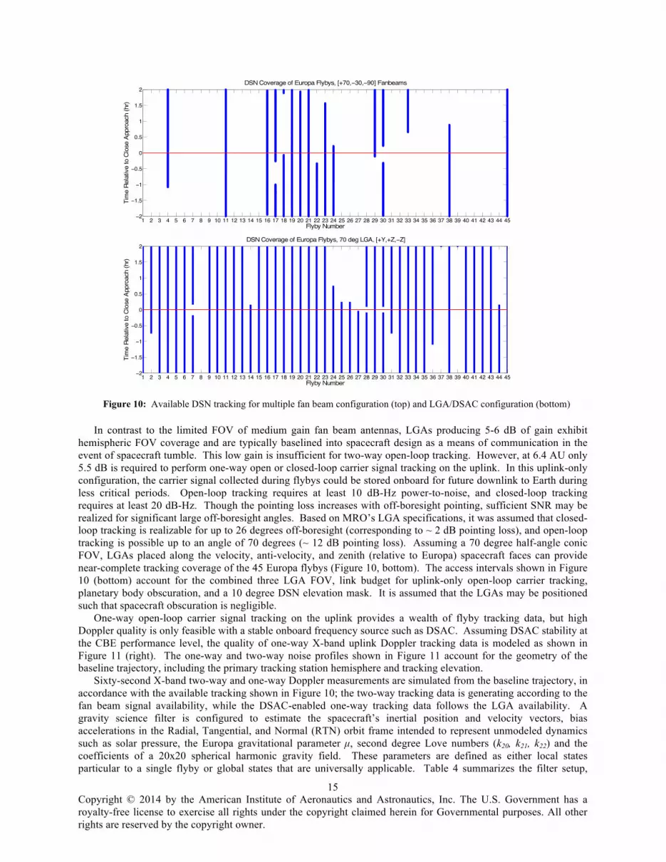
One-way open-loop carrier signal tracking on the uplink provides a wealth of flyby tracking data, but high Doppler quality is only feasible with a stable onboard frequency source such as DSAC. Assuming DSAC stability at the CBE performance level, the quality of one-way X-band uplink Doppler tracking data is modeled as shown in Figure 11 (right). The one-way and two-way noise profiles shown in Figure 11 account for the geometry of the baseline trajectory, including the primary tracking station hemisphere and tracking elevation.
Sixty-second X-band two-way and one-way Doppler measurements are simulated from the baseline trajectory, in accordance with the available tracking shown in Figure 10; the two-way tracking data is generating according to the fan beam signal availability, while the DSAC-enabled one-way tracking data follows the LGA availability. A gravity science filter is configured to estimate the spacecraft’s inertial position and velocity vectors, bias accelerations in the Radial, Tangential, and Normal (RTN) orbit frame intended to represent unmodeled dynamics such as solar pressure, the Europa gravitational parameter µ, second degree Love numbers (k20, k21, k22) and the coefficients of a 20x20 spherical harmonic gravity field. These parameters are defined as either local states particular to a single flyby or global states that are universally applicable. Table 4 summarizes the filter setup,
Figure 10: Available DSN tracking for multiple fan beam configuration (top) and LGA/DSAC configuration (bottom)
1 2 3 4 5 6 7 8 9 10 11 12 13 14 15 16 17 18 19 20 21 22 23 24 25 26 27 28 29 30 31 32 33 34 35 36 37 38 39 40 41 42 43 44 45−2
−1.5
−1
−0.5
0
0.5
1
1.5
2
Flyby Number
Tim
e R
elat
ive
to C
lose
App
roac
h (h
r)
DSN Coverage of Europa Flybys, [+70,−30,−90] Fanbeams
1 2 3 4 5 6 7 8 9 10 11 12 13 14 15 16 17 18 19 20 21 22 23 24 25 26 27 28 29 30 31 32 33 34 35 36 37 38 39 40 41 42 43 44 45−2
−1.5
−1
−0.5
0
0.5
1
1.5
2
Flyby Number
Tim
e R
elat
ive
to C
lose
App
roac
h (h
r)
DSN Coverage of Europa Flybys, 70 deg LGA, [+Y,+Z,−Z]
Copyright © 2014 by the American Institute of Aeronautics and Astronautics, Inc. The U.S. Government has a royalty-free license to exercise all rights under the copyright claimed herein for Governmental purposes. All other rights are reserved by the copyright owner.
16
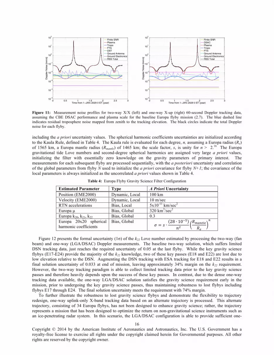
including the a priori uncertainty values. The spherical harmonic coefficients uncertainties are initialized according to the Kaula Rule, defined in Table 4. The Kaula rule is evaluated for each degree, n, assuming a Europa radius (Re) of 1565 km, a Europa mantle radius (Rmantle) of 1465 km; the scale factor, s, is unity for n > 2.16 The Europa gravitational tide Love numbers and second-degree spherical harmonics are assigned very large a priori values, initializing the filter with essentially zero knowledge on the gravity parameters of primary interest. The measurements for each subsequent flyby are processed sequentially, with the a posteriori uncertainty and correlation of the global parameters from flyby N used to initialize the a priori covariance for flyby N+1; the covariance of the local parameters is always initialized as the uncorrelated a priori values shown in Table 4.
Table 4: Europa Flyby Gravity Science Filter Configuration
Estimated Parameter Type A Priori Uncertainty Position (EME2000) Dynamic, Local 100 km Velocity (EME2000) Dynamic, Local 10 m/sec RTN accelerations Bias, Local 5x10-11 km/sec2 Europa µ Bias, Global 320 km3/sec2 Europa k20, k21, k22 Bias, Global 0.3 Europa 20x20 spherical harmonic coefficients
Bias, Global 𝜎 = 𝑠 ∙
28 ∙ 10!!
𝑛!𝑅!"#$%&𝑅!
!
Figure 12 presents the formal uncertainty (1σ) of the k22 Love number estimated by processing the two-way (fan
beam) and one-way (LGA/DSAC) Doppler measurements. The baseline two-way solution, which suffers limited DSN tracking data, just reaches the required uncertainty of 0.05 at the last flyby. While the key gravity science flybys (E17-E24) provide the majority of the k22 knowledge, two of these key passes (E18 and E22) are lost due to low elevation relative to the DSN. Augmenting the DSN tracking with ESA tracking for E18 and E22 results in a final solution uncertainty of 0.033 at end of mission, leaving approximately 34% margin on the k22 requirement. However, the two-way tracking paradigm is able to collect limited tracking data prior to the key gravity science passes and therefore heavily depends upon the success of these key passes. In contrast, due to the dense one-way tracking data available, the one-way LGA/DSAC solution satisfies the gravity science requirement early in the mission, prior to undergoing the key gravity science passes, thus maintaining robustness to lost flybys including flybys E17 through E24. The final solution uncertainty meets the requirement with 74% margin.
To further illustrate the robustness to lost gravity science flybys and demonstrate the flexibility to trajectory redesign, one-way uplink-only X-band tracking data based on an alternate trajectory is processed. This alternate trajectory, consisting of 34 Europa flybys, has not been designed to enhance gravity science; rather, the trajectory represents a mission that has been designed to optimize the return on non-gravitational science instruments such as an ice-penetrating radar system. In this scenario, the LGA/DSAC configuration is able to provide sufficient one-
Figure 11: Measurement noise profiles for two-way X/X (left) and one-way X-up (right) 60-second Doppler tracking data, assuming the CBE DSAC performance and plasma scale for the baseline Europa flyby mission (2.7). The blue dashed line indicates residual troposphere noise mapped from zenith to the tracking elevation. The black circles indicate the total Doppler noise for each flyby.
0 0.5 1 1.5 2 2.5 310−5
10−4
10−3
10−2
10−1
100
101
102
Time from 1−JAN−2029 0 ET (year)
Dop
pler
Noi
se [m
m/s
]
Finite SNRPlasmaTropoFTSDSTGround AntennaGround ElectronicsRSS Total
0 0.5 1 1.5 2 2.5 310−5
10−4
10−3
10−2
10−1
100
101
102
Time from 1−JAN−2029 0 ET (year)
Dop
pler
Noi
se [m
m/s
]
Finite SNRDSACPlasmaTropoFTSGround AntennaGround ElectronicsRSS Total

Copyright © 2014 by the American Institute of Aeronautics and Astronautics, Inc. The U.S. Government has a royalty-free license to exercise all rights under the copyright claimed herein for Governmental purposes. All other rights are reserved by the copyright owner.
17
way tracking data to still satisfy the gravity science requirement in 28 flybys as shown in Figure 13, thus still robust to lost flybys, and maintains 30% margin on the final solution.
Due to the quantity of tracking data available when operating in a DSAC-enabled one-way uplink open-loop tracking architecture, the gravity science objective can be met with no perturbation to the trajectory design and therefore allow the mission to prioritize other science objectives. Furthermore, the use of LGAs to track the Doppler signal onboard during Europa close approach requires very little perturbation to the nominal spacecraft design, and allows for the Doppler signal to be tracked regardless of HGA pointing during critical events. DSAC enables a low SNR telecommunications design to provide one-way X-band Doppler data that is more accurate than the alternative two-way X-band Doppler data, and provides a means to perform high quality gravity science in a flyby scenario in which gravity science success is very strongly correlated to both data quantity and quality.
IV. Conclusion The Deep Space Atomic Clock offers the possibility to alter the traditional paradigm of radiometric tracking
by allowing navigation to rely upon unprecedented high-stability, high-accuracy one-way signals for navigation and radio science purposes. Not only will this change provide improved data quantity and quality, but it will also enhance tracking architecture flexibility and robustness. More over, in certain flight system designs DSAC provides an attractive option for getting more radio science data in low power signal scenarios without significantly modifying the flight system.
Acknowledgments This research was carried out at the Jet Propulsion Laboratory, California Institute of Technology, under a
contract with the National Aeronautics and Space Administration.
References 1 Prestage, J. D., and Weaver, G. L., “Atomic Clocks and Oscillators for Deep-Space Navigation and Radio
Science,” Proceedings of the IEEE, vol. 95, Nov. 2007, pp. 2235–2247. 2 Ely, T. A., Murphy, D., Seubert, J., Bell, J., and Kuang, D., “Expected Performance of the Deep Space
Atomic Clock Mission,” AAS/AIAA Space Flight Mechanics Meeting, Santa Fe, NM: 2014. 3 Riedel, J. E., Bhaskaran, S., Desai, P. N., Han, D., Kennedy, B., Null, G. W., Synnott, S. P., Wang, T. C.,
Werner, R. A., Zamani, E. B., McElrath, T., and Ryne, M., “Deep Space 1 Technology Validation Reports: Autonomous Optical Navigation,” 1999.
Figure 12: Gravity recovery performance for fan beam and LGA/DSAC configurations
1 2 3 4 5 6 7 8 9 10 11 12 13 14 15 16 17 18 19 20 21 22 23 24 25 26 27 28 29 30 31 32 33 34 35 36 37 38 39 40 41 42 43 44 450
0.05
0.1
0.15
0.2
0.25
0.3
Flyby Number
k 22 1−m
Unc
erta
inty
Two−way w/ Three Fanbeams, DSNTwo−way w/ Three Fanbeams, DSN + ESAOne−way w/ Three LGAs + DSAC

Copyright © 2014 by the American Institute of Aeronautics and Astronautics, Inc. The U.S. Government has a royalty-free license to exercise all rights under the copyright claimed herein for Governmental purposes. All other rights are reserved by the copyright owner.
18
4 Kubitschek, D. G., Mastrodemos, N., Werner, R. A., Synnott, S. P., Bhaskaran, S., Riedel, J. E., Kennedy, B. M., Null, G. W., and Vaughan, A. T., “The Challenges of Deep Impact Autonomous Navigation,” Journal of Field Robotics, vol. 24, 2007, pp. 339–354.
5 Hastrup, R. C., Bell, D. J., Cesarone, R. J., Edwards, C. D., Ely, T. A., Guinn, J. R., Rosell, S. N., Srinivasan, J. M., and Townes, S. A., “Mars network for enabling low-cost missions,” Acta Astronautica, vol. 52, 2003, pp. 227–235.
6 Edwards, C. D., Adams, J. T., Bell, D. J., Cesarone, R., DePaula, R., Durning, J. F., Ely, T. A., Leung, R. Y., McGraw, C. A., and Rosell, S. N., “Strategies for telecommunications and navigation in support of Mars exploration,” Acta Astronautica, vol. 48, 2001, pp. 661–668.
7 Flanegan, M., Gal-Edd, J., Anderson, L., Warner, J., Ely, T. A., Lee, C., Shah, B., Vaisnys, A., and Schier, J., “NASA’s Lunar Communication and Navigation Architecture,” ESA/EUMETSAT/AIAA SpaceOps 2008, Heidelberg, Germany: 2008.
8 Lightsey, E. G., Mogensen, A. E., Burkhart, P. D., Ely, T. A., and Duncan, C., “Real-Time Navigation for Mars Missions using the Mars Network,” AIAA Journal of Spacecraft and Rockets, vol. 45, 2008, pp. 519–533.
9 Shin, D., and Pham, T., DSN Telecommunications Link Design Handbook, 202, Rev. B., Jet Propulsion Laboratory, California Institute of Technology, 2010.
10 Taylor, J., Sakamoto, L., and Wong, C.-J., Cassini Orbiter/Huygens Probe Telecommunications, Jet Propulsion Laboratory, California Institute of Technology, 2002.
11 Iess, L., Di Benedetto, M., Marabucci, M., and Racioppa, P., “Improved Doppler Tracking Systems for Deep Space Navigation,” 23rd International Symposium on Space Flight Dynamics, Pasadena, CA: 2012.
12 Folkner, W. M., Effects of Uncalibrated Charged Particles on Doppler Tracking, 1994. 13 Tjoelker, R., and Pham, T., DSN Telecommunications Link Design Handbook, 304, Rev. A, Jet Propulsion
Laboratory, California Institute of Technology, 2010. 14 Asmar, S. W., Armstrong, J. W., Iess, L., and Tortora, P., “Spacecraft Doppler tracking: Noise budget and
accuracy achievable in precision radio science observations,” Radio Science, vol. 40, Apr. 2005, p. n/a–n/a. 15 Abbate, S. F., Armstrong, J. W., Asmar, S. W., Barbinis, E., Bertotti, B., Fleischman, D. U., Gatti, M. S.,
Goltz, G. L., Herrera, R. G., Iess, L., Lee, K. J., Ray, T. L., Tinto, M., Tortora, P., and Wahlquist, H. D., “The Cassini gravitational wave experiment,” Astronomical Telescopes and Instrumentation, M. Cruise and P. Saulson, eds., International Society for Optics and Photonics, 2003, pp. 90–97.
16 You, T.-H., Halsell, A., Graat, E., Demcak, S., Highsmith, D., Long, S., Mottinger, N., Higa, E., and Jah, M., “Navigating Mars Reconnaissance Orbiter: Launch Through Primary Science Orbit,” AIAA Space 2007 Conference and Exposition, Long Beach, CA: 2007.
17 Zuber, M. T., Lemoine, F. G., Smith, D. E., Konopliv, A. S., Smrekar, S. E., and Asmar, S. W., “Mars Reconnaissance Orbiter Radio Science Gravity Investigation,” Journal of Geophysical Research, vol. 112, May 2007, p. E05S07.
18 Park, R. S., Asmar, S. W., Buffington, B. B., Bills, B., Campagnola, S., Chodas, P. W., Folkner, W. M., Konopliv, A. S., and Petropoulos, A. E., “Detecting tides and gravity at Europa from multiple close flybys,” Geophysical Research Letters, vol. 38, Dec. 2011.
19 Pappalardo, R., Cooke, B., Goldstein, B., Prockter, L., Senske, D., and Magner, T., “2013 Europa Clipper Update, NASA Outer Planets Assessment Group” Available: http://www.lpi.usra.edu/opag/jul2013/presentations/Clipper_Summary.pdf.

Copyright © 2014 by the American Institute of Aeronautics and Astronautics, Inc. The U.S. Government has a royalty-free license to exercise all rights under the copyright claimed herein for Governmental purposes. All other rights are reserved by the copyright owner.
19
Figure 13: Gravity recovery performance for DSAC-enabled one-way X-band uplink tracking given an alternate flyby trajectory
1 2 3 4 5 6 7 8 9 10 11 12 13 14 15 16 17 18 19 20 21 22 23 24 25 26 27 28 29 30 31 32 33 340
0.05
0.1
0.15
0.2
0.25
0.3
k 22 1ïS
igm
a U
ncer
tain
ty
Flyby Number
Oneïway Xïup w/ DSAC


