Embed Size (px)
Citation preview
Adhesion phenomena in ferrofluids
José A. Miranda* and Rafael M. OliveiraLaboratório de Física Teórica e Computacional, Departamento de Física, Universidade Federal de Pernambuco, Recife,
Pernambuco 50670-901, Brazil
David P. JacksonDepartment of Physics and Astronomy, Dickinson College, Carlisle, Pennsylvania 17013, USA
(Received 4 March 2004; published 21 September 2004)
One efficient way of determining the bond strength of adhesives is to measure the force or the work requiredto separate two surfaces bonded by a thin adhesive film. We consider the case in which the thin film is not aconventional adhesive material but a high viscosity ferrofluid confined between two narrowly spaced parallelflat plates subjected to an external magnetic field. Our theoretical results demonstrate that both the peakadhesive force and the separation energy are significantly influenced by the action and symmetry properties ofthe applied field. Specifically, we show that the adhesive strength of a ferrofluid is reduced if the appliedmagnetic field is perpendicular to the plates or if the applied field is in plane and exhibits azimuthal symmetry.Conversely, the adhesive strength can be either enhanced or reduced if the applied field is in plane and isdirected radially outward. This establishes an interesting connection between adhesion and ferrohydrodynamicphenomena, allowing the control of important adhesive properties by magnetic means.
DOI: 10.1103/PhysRevE.70.036311 PACS number(s): 47.65.1a, 75.50.Mm, 68.35.Np
I. INTRODUCTION
The study of adhesive materials is vastly multidisciplinaryand its basic scientific research involves a broad spectrum ofareas ranging from interfacial science and rheology to patternformation and chemistry[1,2]. On the practical side, the phe-nomenon of adhesion is part of our everyday lives, and ad-hesive tape industries are among the most active and profit-able [3].
One key aspect on both scientific and practical levels is toprecisely evaluate, characterize, and hopefullycontrol, thebond strength of adhesives. One efficient and relativelysimple way to study important adhesive properties is pro-vided by the so-called probe-tack test[4,5], which measuresthe force required to separate two surfaces bonded by a thinadhesive film. The result of such a test is a force-distancecurve, that describes the behavior of the adhesive film undertension. Good adhesives typically present highly nonlinearforce-distance curves, in which the force increases sharply,reaches a maximum value, and then drops abruptly, defininga plateau, before it eventually vanishes. From these curvesthe separation energy(work done during the entire separationprocess), as well as the peak adhesive force, can be deter-mined.
Recently, several groups began investigating the funda-mentals of adhesion in viscous liquids[6–10]. By dealingwith simpler Newtonian and non-Newtonian fluids, these in-teresting studies tried to gain more insight into the relationbetween the complicated rheological properties of conven-tional adhesives and the force-distance curves. Some note-worthy findings include the appearance of a cavitation-induced force plateau for high separation velocities in very
viscous fluids[7], and the important verification of a modestinfluence of fingering instabilities on the shape of the curves[8]. As systematically proposed by Francis and Horn[6], allthese works[6–10] take into account the significant depen-dence of the force-distance curves on the compliance of themeasurement apparatus.
In this paper we consider the case in which the fluid usedin the adhesion probe-tack test is a magnetic liquid called aferrofluid. The field of ferrofluid research is also highly in-terdisciplinary, bringing physicists, chemists, engineers, andeven physicians together[11,12]. Ferrofluids are colloidalsuspensions of nanometer-sized magnetic particles sus-pended in a nonmagnetic carrier fluid. These fluids behavesuperparamagnetically and can easily be manipulated withexternal magnetic fields that can act to either stabilize ordestabilize the fluid interface. As a result of the ferrofluidinteraction with the external field in confined geometries, theusual viscous fingering instability(Saffman-Taylor instability[13]) is supplemented by a magnetic fluid instability[11,12],resulting in a variety of interesting interfacial behaviors. De-pending on the applied field direction, one observes highlybranched, labyrinthine structures[14–17], patterns showingan ordered line of peaks[18], or even the suppression ofviscosity-driven[19] and centrifugally induced[20,21] inter-facial instabilities in thin ferrofluid films.
We stress that although these ferrofluids are viscous andmagnetic, they are not, rigorously speaking, “true”(non-Newtonian) adhesives. However, in certain situations thesefluids have properties that are quite similar to regular adhe-sives. Here we show that, in contrast to conventional adhe-sive materials, the adhesive properties of a ferrofluid can beenhanced or reduced by varying the intensity of an externallyapplied magnetic field. This effect could be used to designversatile adhesive materials with highly flexible propertiesthat vary with magnetic field, in which the bonding betweensurfaces could be manipulated in a nondestrucitve way. The*Email address: [email protected]
PHYSICAL REVIEW E 70, 036311(2004)
1539-3755/2004/70(3)/036311(10)/$22.50 ©2004 The American Physical Society70 036311-1
simplicity and potential usefulness of such a regulatorymechanism could be of great value in many applications.
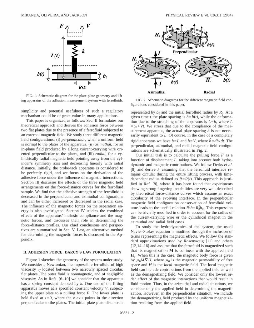
This paper is organized as follows: Sec. II formulates ourtheoretical approach and derives the adhesion force betweentwo flat plates due to the presence of a ferrofluid subjected toan external magnetic field. We study three different magneticfield configurations:(i) perpendicular, when a uniform fieldis normal to the plates of the apparatus,(ii ) azimuthal, for anin-plane field produced by a long current-carrying wire ori-ented perpendicular to the plates, and(iii ) radial, for a cy-lindrically radial magnetic field pointing away from the cyl-inder’s symmetry axis and decreasing linearly with radialdistance. Initially, the probe-tack apparatus is considered tobe perfectly rigid, and we focus on the derivation of theadhesive force under the influence of magnetic interactions.Section III discusses the effects of the three magnetic fieldarrangements on the force-distance curves for the ferrofluidsample. We find that the adhesive strength of the ferrofluid isdecreased in the perpendicular and azimuthal configurationsand can be either increased or decreased in the radial case.The influence of the magnetic forces on the separation en-ergy is also investigated. Section IV studies the combinedeffects of the apparatus’ intrinsic compliance and the mag-netic forces, and discusses their role in determining theforce-distance profiles. Our chief conclusions and perspec-tives are summarized in Sec. V. Last, an alternative methodfor determining the magnetic forces is discussed in the Ap-pendix.
II. ADHESION FORCE: DARCY’S LAW FORMULATION
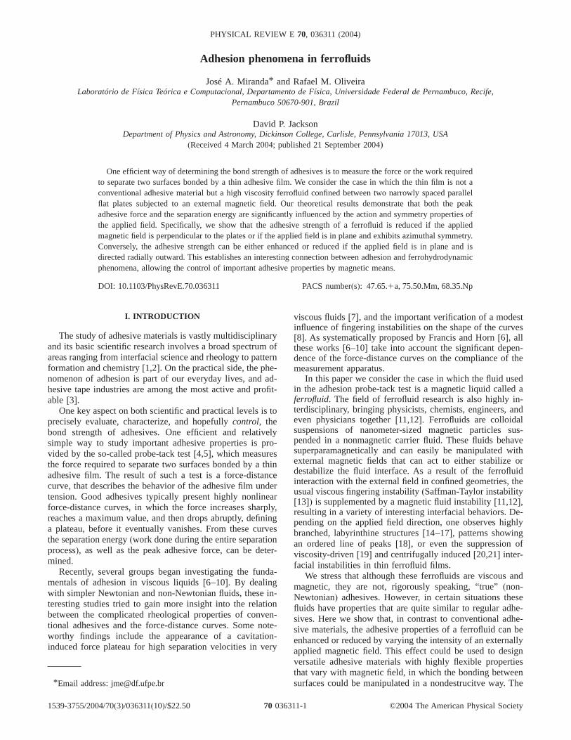
Figure 1 sketches the geometry of the system under study.We consider a Newtonian, incompressible ferrofluid of highviscosity h located between two narrowly spaced circular,flat plates. The outer fluid is nonmagnetic, and of negligibleviscosity. As in Refs.[6–10] we consider that the apparatushas a spring constant denoted byk. One end of the liftingapparatus moves at a specified constant velocityV, subject-ing the upper plate to a pulling forceF. The lower plate isheld fixed atz=0, where thez axis points in the directionperpendicular to the plates. The initial plate-plate distance is
represented byb0 and the initial ferrofluid radius byR0. At agiven timet the plate spacing isb=bstd, while the deforma-tion due to the stretching of the apparatus isL−b, whereL=b0+Vt. We stress that due to the compliance of the mea-surement apparatus, the actual plate spacingb is not neces-sarily equivalent toL. Of course, in the case of a completelyrigid apparatus we haveb=L andb=V, whereb=db/dt. Theperpendicular, azimuthal, and radial magnetic field configu-rations are schematically illustrated in Fig. 2.
Our initial task is to calculate the pulling forceF as afunction of displacementL, taking into account both hydro-dynamic and magnetic contributions. We follow Derkset al.[8] and deriveF assuming that the ferrofluid interface re-mains circular during the entire lifting process, with time-dependent radius defined asR=Rstd. This approach is justi-fied in Ref. [8], where it has been found that experimentsshowing strong fingering instabilities are very well describedby theoretical force-distance curves which assume an exactcircularity of the evolving interface. In the perpendicularmagnetic field configuration conservation of ferrofluid vol-ume leads to the useful relationR2b=R0
2b0. This expressioncan be trivially modified in order to account for the radius ofthe current-carrying wire or the cylindrical magnet in theazimuthal and radial field cases.
To study the hydrodynamics of the system, the usualNavier-Stokes equation is modified through the inclusion ofterms representing the magnetic effects. We follow the stan-dard approximations used by Rosensweig[11] and others[12,14–16] and assume that the ferrofluid is magnetized suchthat its magnetizationM is collinear with the applied fieldHa. When this is the case, the magnetic body force is givenby m0M =H, wherem0 is the magnetic permeability of freespace andH is the local magnetic field. The local magneticfield can include contributions from the applied field as wellas the demagnetizing field. We consider only the lowest or-der effect of the magnetic interactions that would result influid motion. Thus, in the azimuthal and radial situations, weconsider only the applied field in determining the magneti-zation. However, in the perpendicular situation, we includethe demagnetizing field produced by the uniform magnetiza-tion resulting from the applied field.
FIG. 1. Schematic diagram for the plate-plate geometry and lift-ing apparatus of the adhesion measurement system with ferrofluids. FIG. 2. Schematic diagrams for the different magnetic field con-
figurations considered in this paper.
MIRANDA, OLIVEIRA, AND JACKSON PHYSICAL REVIEW E 70, 036311(2004)
036311-2
For the quasi-two-dimensional plate-plate geometry, weemploy the lubrication approximation and reduce the three-dimensional flow to an equivalent two-dimensional flowUsr ,ud by averaging over the direction perpendicular to theplates(z axis), wheresr ,ud denote polar coordinates. Usingno-slip boundary conditions and neglecting inertial terms,one derives a modified Darcy’s law as[16,22]
U = −b2
12h= P j . s1d
The generalized pressureP j =p−C j in Eq. (1) contains boththe hydrodynamic pressurep and a magnetic pressure repre-sented by a scalar potentialC j. The subscriptj =1,2,3indi-cates the perpendicular, azimuthal, and radial magnetic fieldconfigurations, respectively.
We can exploit the irrotational nature of the flow to obtainthe two-dimensional flow field byz averaging the full three-dimensional incompressibility condition= ·v=0. This yields
Usrd=−sbr /2bder, whereer is a unit vector in the radial di-rection. This allows us to integrate Eq.(1) to obtain the pres-sure field
P jsrd =3hb
b3 sr2 − R2d + P jsRd, s2d
whereP jsRd is the value of the generalized pressure at theferrofluid droplet boundary. To determineP jsRd we use thefacts thatC j =0 in the nonmagnetic fluid and the pressurejump at the interface of a magnetic fluid given by[11,12]
Dp = sk −1
2m0Mn
2. s3d
Here,s is the surface tension,k is the curvature of the in-terface, andMn represents the normal component of the mag-netization at the interface. In the present case,Mn is given bythe radial component evaluated atr =R, namely,Mn=MrsRd.These boundary conditions result in a pressure field given by
P jsrd =3hb
b3 sr2 − R2d + p0 − C jsRd −1
2m0Mjr
2 sRd, s4d
where p0 denotes the atmospheric pressure outside the fer-rofluid droplet. As is common in this type of adhesion phe-nomena[6–10], we have neglected the surface tension termin Eq. (4).
In the nonmagnetic case, the inward viscous flow inducedby traction is accompanied by a pressure gradient pointingoutward. Therefore in the absence of an applied magneticfield the border of the ferrofluid droplet is at atmosphericpressurep0 while the interior of the sample is at a lowerpressure. From Eq.(4) we see that the purely viscous, non-magnetic contribution to the pressure in the sample is nega-tive. In other words, when the upper plate is lifted, the pres-sure gradient causes an inward viscous shearing flow in theplane of the adhesive film, producing a downward adhesiveforce normal to the upper plate. When a magnetic field isapplied, the magnetic contributions in Eq.(4) can modify
this scenario significantly. In fact, as we now show, addi-tional magnetic terms come into play when calculating theadhesion force.
Since it is the generalized pressureP j that results in fluidmotion according to Eq.(1), the force exerted by the liftingmachine on the upper plate is calculated by integrating thegeneralized pressure difference above and below the upperplate, taking into account the pressure jump condition(3)across the magnetic fluid surface in contact with the upperplate. The net force of separation(adhesion force) is thengiven by
Fj =E dAH3hb
b3 sR2 − r2d + fC jsRd − C jsrdg
+1
2m0fMjr
2 sRd − Mjz2 srdgJ , s5d
where the integration is carried out over the cross sectionalarea of the ferrofluid dropA. In the perpendicular case, thisis simply a circle of radiusR. But in the azimuthal and radialsituations, this is an annulus of outer radiusR and innerradiusa. The termMjz
2 srd denotes the normal component ofthe magnetization evaluated at the boundaryz=b. An alter-native way of calculating the magnetic terms appearing inthe adhesion force Eq.(5) is presented and discussed in theAppendix.
We can gain some physical insight into the adhesion forceequation simply by looking at the sign of the magnetic terms.Positive magnetic terms in Eq.(5) lead to increased adhesionwhile negative terms lead to decreased adhesion. In particu-lar, any radial magnetization at the boundary of the domainwill tend to increase adhesion while magnetization normal tothe plates will tend to decrease adhesion. This can be under-stood qualitatively by noting that the effect of the normalcomponent of the magnetization at the fluid interfacer =R isto “push” outward on the interface. Thus magnetization thatpushes outward at the boundary of the domain leads to thefluid attempting to “spread out” in the plane of the sample.This results in a downward force on the upper plate and anincrease in adhesion. Conversely, magnetization that pushesupward on the upper surfacez=b will exert an upward forceon the plate, resulting in decreased adhesion. The effect ofthe other magnetic terms in Eq.(5) will depend on the formof the scalar potential.
Equation(5) is one of the central results of this work. Theremainder of this paper looks into the details of how themagnetic effects alter the adhesion force for three differentmagnetic field configurations.
A. Perpendicular magnetic field
First, we consider the perpendicular field cases j =1d inwhich a uniform magnetic fieldHa=H0ez is applied normalto the plates. This situation was studied in Refs.[15,23] byassuming the ferrofluid has a uniform magnetizationM0=MsH0d. Here,MsHd gives the(possibly nonlinear) relation-ship between the magnetization and the applied field. Thisconfiguration is then equivalent to a uniformly charged
ADHESION PHENOMENA IN FERROFLUIDS PHYSICAL REVIEW E70, 036311(2004)
036311-3
parallel-plate capacitor and a scalar potential can be writtenin a number of equivalent forms[16]. However, in contrastto the situation studied in Refs.[15,16,23], which only re-quired the magnetic pressure at theinterfaceof a fingereddroplet, we are interested in calculatingC1 for an arbitrarypoint r of a circular magnetic domains0ø r øRd. In particu-lar, since we are interested in pointswithin as well ason thedomain boundary, it is essential to choose a form forC1 thatis continuousat the boundary. If we describe the ferrofluidboundary by a simple closed curveC parametrized by ar-clengths, then a convenient way of writing the scalar poten-tial is (see Ref.[16])
C1 =m0M
2
2pb HRC
ds8D 3 tss8d
+RC
dx8 lnfsy − y8d + ÎD2 + b2 gJ , s6d
wherex=xssd, x8=xss8d, etc., tss8d is the unit tangent vector
at arclengths8, and D=D /D is the unit difference vectorpointing from the pointr =sx,yd to the pointr 8=sx8 ,y8d.
Unfortunately, even though we assume the ferrofluidsample maintains a circular shape during the lifting of theupper plate, the evaluation of Eq.(6) for arbitrary pointslocated inside the sample does not result in a simple closed-form expression. Substituting Eq.(6) into Eq.(5) results in adimensionlessforce
F1 =b
b5 + NB'H 2
R02E
0
R
Isrdrdr − Sb0
bDFIsRd +
p
2GJ , s7d
where
Isrd =E0
p/2 S zQ + P2sin2 v
ÎQ2 + P2sin2 vDdv
+1
2E
0
p
lnFÎ1 + Q2 + P2sin2 v −1
2z sin 2vG
3z sin 2v dv, s8d
z=2R/b, Q=sR−rd /b, P2=4rR/b2, andNB'=m0M
2R02/kd is
the magnetic Bond number for the perpendicular magneticfield configuration. Similar to what is done in Refs.[6,8,10],in Eq. (7) lengths have been re-scaled byd=s3phR0
4b02V/2kd1/6 and velocities byV. It is worth mention-
ing again that since we are dealing with the noncompliant
situation, we haveb=L and henceb=1. Equation(7) shows
b explicitly in anticipation of our analysis of the compliantapparatus situation.
B. Azimuthal magnetic field
For the azimuthal field cases j =2d we consider a longstraight current-carrying wire that is perpendicular to(co-axial with) the plates(see Fig. 2). This may present an ex-perimental challenge because the hole necessary for the wirecould result in leakage. The magnetic field produced by this
wire is Ha= I / s2prdeu=sH0a/ rdeu, where I represents theelectric current,a is the radius of the current-carrying wire,and eu is a unit vector in the azimuthal direction. The mag-netization is collinear with the magnetic field and is writtenM =sM0a/ rdeu, whereM0=MsH0d. Here again,MsHd givesthe (possibly nonlinear) relationship between the magnetiza-tion and the applied field. In this case, the scalar potentialcan be simply written as[20]
C2srd =m0M0H0a
2
2r2 . s9d
We note that the magnetization in this configuration is every-where tangential to the interface, and also to the upper sur-face of the ferrofluid sample. Thus there are no “surface”contributions to the adhesion force. Furthermore, we notethat fC2sRd−C2srdg will always be negative so that the mag-netic contribution in the azimuthal case tends to reduce thebond strength of the ferrofluid. This makes good physicalsense because the radial gradient results in a magnetic forcedirected radially inward leading to an increased pressure thatpushes upward on the upper surface.
Under such circumstances, the evaluation of Eq.(5) forthe azimuthal field case leads to thedimensionlessforce
F2 =b
b5Sg − 1
gD2
− NBazi5lnF1 + sg − 1d
b0
bG
− 3 sg − 1db
b0+ sg − 1d46 , s10d
where g=sR0/ad2 and NBazi=spm0M0H0a
2d / s2kdd is a mag-netic Bond number for the azimuthal magnetic field configu-ration. In the case of a linear relationshipM =xH, the Bondnumber can be writtenNB
azi=sm0xI2d / s8pkdd. As in the per-pendicular field case, lengths and velocities in Eq.(10) have
been re-scaled byd andV, respectively, andb=1.
C. Radial magnetic field
Last, we consider a cylindrically radial magnetic fieldconfigurations j =3d [24–26] such thatHa=sH0a/ rder. Theexperimental conditions required to obtain such a radialmagnetic field are discussed in Ref.[24]. Roughly speaking,the radial field is produced by shaping the poles of a perma-nent magnet into concentric cylinders. As before, we assumethe magnetization is collinear with the applied field so thatM =sM0a/ rder, where M0=MsH0d. In this case, the scalarpotential can be written as
C3srd =m0M0H0a
2
2r2 . s11d
Note that the scalar potential in this situation is exactly thesame as in the azimuthal field configuration. Thus we alreadyknow that the force resulting from this potential will tend todecrease the adhesion force. However, unlike the azimuthalcase, the radial magnetization will lead to a “surface” force
MIRANDA, OLIVEIRA, AND JACKSON PHYSICAL REVIEW E 70, 036311(2004)
036311-4
term that will tend toincreaseadhesion. Under such circum-stances, the evaluation of Eq.(5) for the radial field caseleads to adimensionlessforce
F3 =b
b5Sg − 1
gD2
− NBrad5lnF1 + sg − 1d
b0
bG − S1 +
M0
H0D
33 sg − 1db
b0+ sg − 1d46 , s12d
whereg=sR0/ad2 and NBrad=spm0M0H0a
2d / s2kdd is a mag-netic Bond number for the radial magnetic field configura-tion. In the case of a linear relationshipM =xH, the Bondnumber can be writtenNB
rad=spm0xH02d / s2kdd. As in the
other cases, lengths and velocities in Eq.(12) have been
re-scaled byd andV, respectively, andb=1.We note in passing that by taking the limita→0 and
eliminating the magnetic terms(by simply dropping theterms involving the magnetic Bond numbers), all three forceequations(7), (10), and(12) reduce to the equivalent expres-sion derived in Ref.[8] for nonmagnetic viscous fluids. Aswe will see in the remaining sections, the magnetic termsappearing in these force expressions enrich the physics in-volved considerably, establishing an interesting link betweenadhesion and magnetic phenomena.
III. NONCOMPLIANT APPARATUS CASE
Before turning our attention to the complete force-distance curves including compliance and magnetic effects,let us analyze Eqs.(7), (10), and (12) in greater detail and
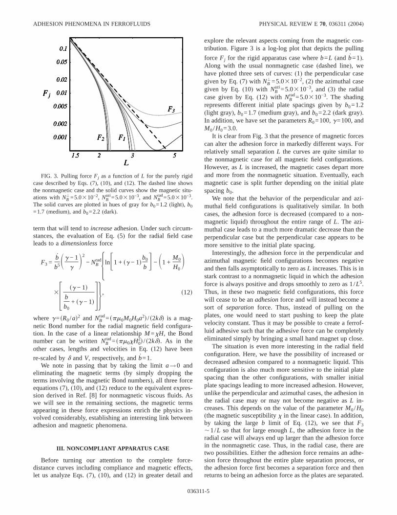
explore the relevant aspects coming from the magnetic con-tribution. Figure 3 is a log-log plot that depicts the pulling
force Fj for the rigid apparatus case whereb=L (and b=1).Along with the usual nonmagnetic case(dashed line), wehave plotted three sets of curves:(1) the perpendicular casegiven by Eq.(7) with NB
'=5.0310−2, (2) the azimuthal casegiven by Eq.(10) with NB
azi=5.0310−3, and (3) the radialcase given by Eq.(12) with NB
rad=5.0310−3. The shadingrepresents different initial plate spacings given byb0=1.2(light gray), b0=1.7 (medium gray), andb0=2.2 (dark gray).In addition, we have set the parametersR0=100,g=100, andM0/H0=3.0.
It is clear from Fig. 3 that the presence of magnetic forcescan alter the adhesion force in markedly different ways. Forrelatively small separationL the curves are quite similar tothe nonmagnetic case for all magnetic field configurations.However, asL is increased, the magnetic cases depart moreand more from the nonmagnetic situation. Eventually, eachmagnetic case is split further depending on the initial platespacingb0.
We note that the behavior of the perpendicular and azi-muthal field configurations is qualitatively similar. In bothcases, the adhesion force is decreased(compared to a non-magnetic liquid) throughout the entire range ofL. The azi-muthal case leads to a much more dramatic decrease than theperpendicular case but the perpendicular case appears to bemore sensitive to the initial plate spacing.
Interestingly, the adhesion force in the perpendicular andazimuthal magnetic field configurations becomes negativeand then falls asymptotically to zero asL increases. This is instark contrast to a nonmagnetic liquid in which the adhesionforce is always positive and drops smoothly to zero as 1/L5.Thus, in these two magnetic field configurations, this forcewill cease to be anadhesionforce and will instead become asort of separation force. Thus, instead of pulling on theplates, one would need to start pushing to keep the platevelocity constant. Thus it may be possible to create a ferrof-luid adhesive such that the adhesive force can be completelyeliminated simply by bringing a small hand magnet up close.
The situation is even more interesting in the radial fieldconfiguration. Here, we have the possibility of increased ordecreased adhesion compared to a nonmagnetic liquid. Thisconfiguration is also much more sensitive to the initial platespacing than the other configurations, with smaller initialplate spacings leading to more increased adhesion. However,unlike the perpendicular and azimuthal cases, the adhesion inthe radial case may or may not become negative asL in-creases. This depends on the value of the parameterM0/H0(the magnetic susceptibilityx in the linear case). In addition,by taking the largeb limit of Eq. (12), we see thatF3,1/L so that for large enoughL, the adhesion force in theradial case will always end up larger than the adhesion forcein the nonmagnetic case. Thus, in the radial case, there aretwo possibilities. Either the adhesion force remains an adhe-sion force throughout the entire plate separation process, orthe adhesion force first becomes a separation force and thenreturns to being an adhesion force as the plates are separated.
FIG. 3. Pulling forceFj as a function ofL for the purely rigidcase described by Eqs.(7), (10), and (12). The dashed line showsthe nonmagnetic case and the solid curves show the magnetic situ-ations withNB
'=5.0310−2, NBazi=5.0310−3, and NB
rad=5.0310−3.The solid curves are plotted in hues of gray forb0=1.2 (light), b0
=1.7 (medium), andb0=2.2 (dark).
ADHESION PHENOMENA IN FERROFLUIDS PHYSICAL REVIEW E70, 036311(2004)
036311-5
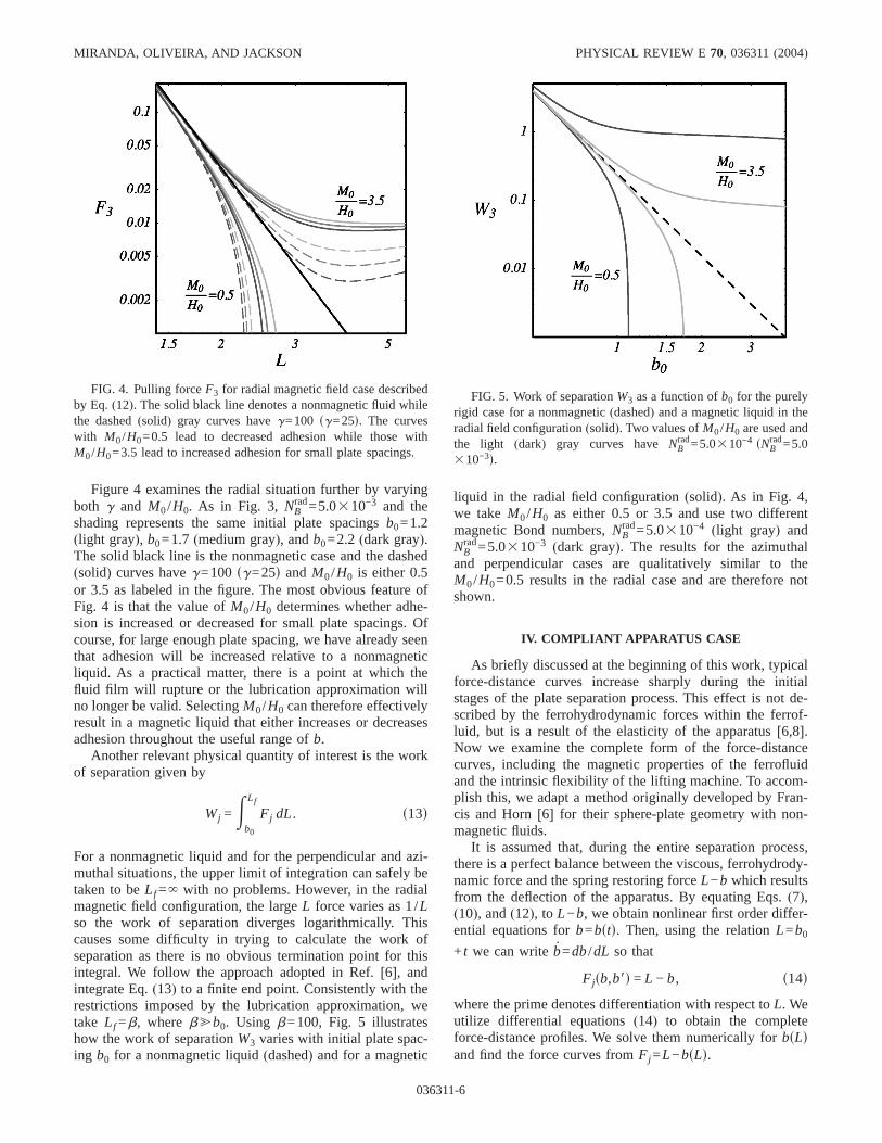
Figure 4 examines the radial situation further by varyingboth g and M0/H0. As in Fig. 3, NB
rad=5.0310−3 and theshading represents the same initial plate spacingsb0=1.2(light gray), b0=1.7 (medium gray), andb0=2.2 (dark gray).The solid black line is the nonmagnetic case and the dashed(solid) curves haveg=100 sg=25d andM0/H0 is either 0.5or 3.5 as labeled in the figure. The most obvious feature ofFig. 4 is that the value ofM0/H0 determines whether adhe-sion is increased or decreased for small plate spacings. Ofcourse, for large enough plate spacing, we have already seenthat adhesion will be increased relative to a nonmagneticliquid. As a practical matter, there is a point at which thefluid film will rupture or the lubrication approximation willno longer be valid. SelectingM0/H0 can therefore effectivelyresult in a magnetic liquid that either increases or decreasesadhesion throughout the useful range ofb.
Another relevant physical quantity of interest is the workof separation given by
Wj =Eb0
Lf
Fj dL. s13d
For a nonmagnetic liquid and for the perpendicular and azi-muthal situations, the upper limit of integration can safely betaken to beLf =` with no problems. However, in the radialmagnetic field configuration, the largeL force varies as 1/Lso the work of separation diverges logarithmically. Thiscauses some difficulty in trying to calculate the work ofseparation as there is no obvious termination point for thisintegral. We follow the approach adopted in Ref.[6], andintegrate Eq.(13) to a finite end point. Consistently with therestrictions imposed by the lubrication approximation, wetake Lf =b, where b@b0. Using b=100, Fig. 5 illustrateshow the work of separationW3 varies with initial plate spac-ing b0 for a nonmagnetic liquid(dashed) and for a magnetic
liquid in the radial field configuration(solid). As in Fig. 4,we takeM0/H0 as either 0.5 or 3.5 and use two differentmagnetic Bond numbers,NB
rad=5.0310−4 (light gray) andNB
rad=5.0310−3 (dark gray). The results for the azimuthaland perpendicular cases are qualitatively similar to theM0/H0=0.5 results in the radial case and are therefore notshown.
IV. COMPLIANT APPARATUS CASE
As briefly discussed at the beginning of this work, typicalforce-distance curves increase sharply during the initialstages of the plate separation process. This effect is not de-scribed by the ferrohydrodynamic forces within the ferrof-luid, but is a result of the elasticity of the apparatus[6,8].Now we examine the complete form of the force-distancecurves, including the magnetic properties of the ferrofluidand the intrinsic flexibility of the lifting machine. To accom-plish this, we adapt a method originally developed by Fran-cis and Horn[6] for their sphere-plate geometry with non-magnetic fluids.
It is assumed that, during the entire separation process,there is a perfect balance between the viscous, ferrohydrody-namic force and the spring restoring forceL−b which resultsfrom the deflection of the apparatus. By equating Eqs.(7),(10), and(12), to L−b, we obtain nonlinear first order differ-ential equations forb=bstd. Then, using the relationL=b0
+ t we can writeb=db/dL so that
Fjsb,b8d = L − b, s14d
where the prime denotes differentiation with respect toL. Weutilize differential equations(14) to obtain the completeforce-distance profiles. We solve them numerically forbsLdand find the force curves fromFj =L−bsLd.
FIG. 4. Pulling forceF3 for radial magnetic field case describedby Eq.(12). The solid black line denotes a nonmagnetic fluid whilethe dashed(solid) gray curves haveg=100 sg=25d. The curveswith M0/H0=0.5 lead to decreased adhesion while those withM0/H0=3.5 lead to increased adhesion for small plate spacings.
FIG. 5. Work of separationW3 as a function ofb0 for the purelyrigid case for a nonmagnetic(dashed) and a magnetic liquid in theradial field configuration(solid). Two values ofM0/H0 are used andthe light (dark) gray curves haveNB
rad=5.0310−4 sNBrad=5.0
310−3d.
MIRANDA, OLIVEIRA, AND JACKSON PHYSICAL REVIEW E 70, 036311(2004)
036311-6
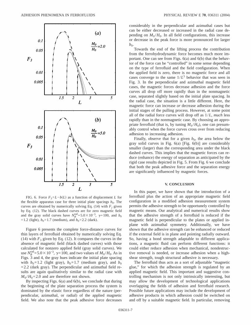
Figure 6 presents the complete force-distance curves forthin layers of ferrofluid obtained by numerically solving Eq.(14) with F3 given by Eq.(12). It compares the curves in theabsence of magnetic field(black dashed curves) with thosecalculated for nonzero applied field(gray solid curves). WeuseNB
rad=5.0310−3, g=100, and two values ofM0/H0. As inFigs. 3 and 4, the gray hues indicate the initial plate spacingwith b0=1.2 (light gray), b0=1.7 (medium gray), and b0=2.2 (dark gray). The perpendicular and azimuthal field re-sults are again qualitatively similar to the radial case withM0/H0=2.0 and are therefore not shown.
By inspecting Figs. 6(a) and 6(b), we conclude that duringthe beginning of the plate separation process the system isdominated by the elastic force regardless of the nature(per-pendicular, azimuthal, or radial) of the applied magneticfield. We also note that the peak adhesive force decreases
considerably in the perpendicular and azimuthal cases butcan be either decreased or increased in the radial case de-pending onM0/H0. In all field configurations, this increaseor decrease in the peak force is more pronounced for largerb0.
Towards the end of the lifting process the contributionfrom the ferrohydrodynamic force becomes much more im-portant. One can see from Figs. 6(a) and 6(b) that the behav-ior of the force can be “controlled” in some sense dependingon the type of ferrofluid and the field configuration. Whenthe applied field is zero, there is no magnetic force and allcases converge to the same 1/L5 behavior that was seen inFig. 3. In the perpendicular and azimuthal magnetic fieldcases, the magnetic forces decrease adhesion and the forcecurves all drop off more rapidly than in the nonmagneticcase, separated slightly based on the initial plate spacing. Inthe radial case, the situation is a little different. Here, themagnetic force can increaseor decrease adhesion during theinitial stages of the pulling process. However, at some pointall of the radial force curves will drop off as 1/L, muchlessrapidly than in the nonmagnetic case. By choosing an appro-priate ferrofluid(that is, by tuningM0/H0), one can presum-ably control when the force curves cross over from reducingadhesion to increasing adhesion.
Finally, observe that for a givenb0, the area below thegray solid curves in Fig. 6(a) [Fig. 6(b)] are considerablysmaller(larger) than the corresponding area under the blackdashed curves. This implies that the magnetic forces can re-duce(enhance) the energy of separation as anticipated by therigid case results depicted in Fig. 5. From Fig. 6 we concludethat both the peak adhesive force and the separation energyare significantly influenced by magnetic forces.
V. CONCLUSION
In this paper, we have shown that the introduction of aferrofluid plus the action of an appropriate magnetic fieldconfiguration in a modified adhesion measurement systempermits the adhesive strength to be opportunely controlled bymagnetic means. Our analytical and numerical results showthat the adhesive strength of a ferrofluid is reduced if themagnetic field is perpendicular to the plates or applied in-plane with azimuthal symmetry. Additionally, we haveshown that the adhesive strength can be enhanced or reducedif the external field is in plane and pointing radially outward.So, having a bond strength adaptable to different applica-tions, a magnetic fluid can perform different functions: itcould either reduce adhesion when mechanical, nondestruc-tive removal is needed, or increase adhesion when a high-shear strength, tough structural adhesive is necessary.
The ferrofluid thus acts as a sort of adjustable “magneticglue,” for which the adhesion strength is regulated by anapplied magnetic field. This important and suggestive con-trolling mechanism is not only intrinsically interesting, butmay allow the development of technological applicationsoverlapping the fields of adhesion and ferrofluid research.Possible future applications may include the development ofadhesive products in which adhesion could be switched onand off by a suitable magnetic field. In particular, removing
FIG. 6. ForceF3=L−bsLd as a function of displacementL forthe flexible apparatus case for three initial plate spacingsb0. Thecurves are obtained by numerically solving Eq.(14) with Fj givenby Eq. (12). The black dashed curves are for zero magnetic fieldand the gray solid curves haveNB
rad=5.0310−3, g=100, andb0
=1.2 (light), b0=1.7 (medium), andb0=2.2 (dark).
ADHESION PHENOMENA IN FERROFLUIDS PHYSICAL REVIEW E70, 036311(2004)
036311-7
the adhesive force via a small hand-held magnet seems like avery useful possibility. Recent interesting studies have dem-onstrated that the adhesive properties of some solid/polymerinterfaces can indeed be tuned by temperature[27,28]. Themagnetically monitored adhesive process we present herewould certainly add a welcome versatility to adhesion tech-nology, even possibly allowing the emergence of a system-atic way of controlling the reversibility of adherence usingmagnetic fields.
Our theoretical work makes specific predictions that havenot yet been subjected to experimental check. It would be ofinterest to examine the relationship between adhesion andmagnetic phenomena by performing probe-tack measure-ments with ferrofluids subjected to perpendicular, azimuthal,and in particular, radial magnetic field configurations[24,29,30]; these might even include such configurations asrotating [31–33] magnetic fields. A natural extension of thecurrent work would be the investigation of the influence ofmagnetic forces on the adhesive properties of more complexmagnetic fluids, such as magnetorheological suspensions[34], in which other important effects like elasticity, plastic-ity, shear thinning, and shear thickening could be monitoredby external magnetic fields. In summary, we hope this workwill instigate further theoretical and experimental studies onthis rich topic.
ACKNOWLEDGMENTS
We thank the Brazilian Research Council/CNPq(J.A.M.and R.M.O.) and Dickinson College(D.P.J.) for financialsupport of this research. We gratefully acknowledge usefulcommunications and stimulating discussions with AnkeLindner, Cyprien Gay, José Bico, Michael Widom, RaymondGoldstein, and Alexandre Rosas. We are greatly indebted toAndrejs Cebers for important discussions and useful sugges-tions.
APPENDIX: CALCULATION OF MAGNETIC FORCESUSING AN ENERGY APPROACH
In this work, the magnetic effects were taken into accountvia a modified Darcy’s law given by Eq.(1). This presup-poses that one can write the magnetic forces in terms of ascalar potentialC j. Indeed, the azimuthal and radial configu-rations both led to relatively simple scalar potentials and themagnetic forces could be calculated in closed form as shownin Eqs.(10) and(12). However, in the perpendicular configu-ration the scalar potential is a more complicated integral ex-pression given by Eqs.(6) and(8) that leads to an even morecomplex expression for the force via Eq.(7). Because of thedifficulties involved in calculating the forces in the perpen-dicular situation, we wondered whether there was an alterna-tive method for calculating this force.
Because most of our difficulties involved integratingrather complicated expressions, it seemed appropriate to tryto find the force using a differentiation process. Specifically,for a ferrofluid droplet whose magnetic energy is given as afunction of height byEmsbd, the force exerted by the ferrof-luid is given by
Fm = −dEm
db. sA1d
Now, the change in magnetic energy obtained by intro-ducing a volume of magnetic fluid into a static magnetic fieldin free space is[11,12]
Em = −1
2E M ·B0dV, sA2d
whereM is the magnetization of the ferrofluid,B0 is the fieldthat would be present in the absence of the ferrofluid, and theintegration is taken over the volume of the ferrofluidV. Forexample, in the azimuthal situation, we have a ferrofluid cy-lindrical annulus of heightb and inner(outer) radiusa (R).To be consistent with the approximations used in the Darcyapproach, we assume the applied magnetic field given byHa=sH0a/ rdeu and magnetization given byM =sM0a/ rdeu.Equation(A2) then gives
Emazi = − pm0M0H0a
2b lnSR
aD . sA3d
Using volume conservation and performing the required dif-ferentiation, we obtain a magnetic force(scaled bykd) of
Fmazi = NB
azi5lnF1 + sg − 1db0
bG −
sg − 1db
b0+ sg − 1d6 , sA4d
whereg and NBazi are as previously defined. Equation(A4)
indicates an upward force and is exactly the same as themagnetic force given in Eq.(10) as expected. Note that theminus sign difference between Eq.(A4) and the correspond-
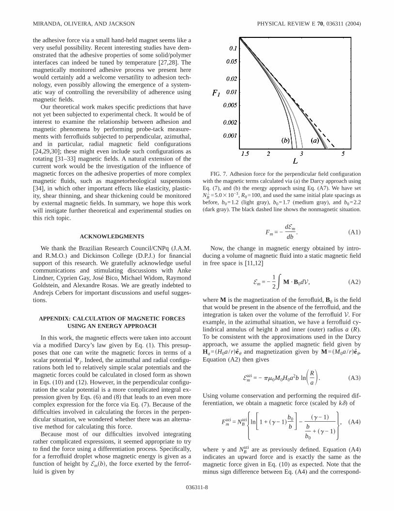
FIG. 7. Adhesion force for the perpendicular field configurationwith the magnetic terms calculated via(a) the Darcy approach usingEq. (7), and (b) the energy approach using Eq.(A7). We have setNB
'=5.0310−3, R0=100, and used the same initial plate spacings asbefore, b0=1.2 (light gray), b0=1.7 (medium gray), and b0=2.2(dark gray). The black dashed line shows the nonmagnetic situation.
MIRANDA, OLIVEIRA, AND JACKSON PHYSICAL REVIEW E 70, 036311(2004)
036311-8
ing terms in Eq.(10) is due to our choice of coordinatesystem in describing the adhesion force.
Let us now try the same approach with the radial fieldconfiguration. In this case we have an applied field given byHa=sH0a/ rder and a magnetization given byM =sM0a/ rder.Carrying out the energy and force calculations, we find thatthe magnetic force in the radial case is exactly the same as inthe azimuthal case given by Eq.(A4). At first this mightseem strange since the radial and azimuthal magnetic fieldspoint in different directions. However, since it is thegradientof the field magnitude that determines the force and the spa-tial dependence is identical in both situations, this should notbe too surprising. What is surprising is the fact that in theradial situation, the magnetic force calculated from the en-ergy as given by Eq.(A4) does not equal the magnetic forcecalculated from the Darcy approach as given in Eq.(12). Thedifference between the two approaches can be traced to the“surface” force term that comes from the boundary condition(3). This means that if we want to use the energy method, wemust augment the force by inclusion of these surface terms.Specifically, Eq.(A1) should be replaced by
Fm = −dEm
db+
1
2m0E dAfMjz
2 srd − Mjr2 sRdg. sA5d
Here, as in Sec. II, the integration is taken over the crosssectional areaA of the ferrofluid surface in contact with theupper plate.
Although Eq.(A5) is not quite as simple as Eq.(A1), it isstill potentially much easier to use in some situations thanEq. (5). As an example, let us now consider the perpendicu-lar field configuration. In this case, the ferrofluid droplet is inthe shape of a cylinder of heightb and radiusR. The energyof this configuration, is, apart from a constant term propor-tional to the volume, given by[14,15]
Em' =
4
3m0M
2R3h1 − q−3fs2q2 − 1dEsqd + s1 − q2dKsqdgj,
sA6d
whereK and E are, respectively, complete elliptic integralsof the first and second kind, andq2=z2/ s1+z2d (recall that
z=2R/b). Again, using volume conservation and performingthe differentiation, Eq.(A5) gives a dimensionless force of
Fm' = NB
'Sb0
bDHq3 − s2 − q2dEsqd + 2s1 − q2dKsqd
q2Î1 − q2+
p
2J ,
sA7d
whereNB' is defined as before.
Equation (A7) gives a closed form expression for themagnetic contribution to the adhesion force in the perpen-dicular field configuration. But this information is suppos-edly contained in Eq.(7) as well. Figure 7 shows the adhe-sion force as calculated using both(a) the Darcy approachand(b) the energy approach. Although qualititatively similar,these two forces are clearlynot the same. The energy ap-proach shows a dramatically decreased adhesion force. Butwhy? It turns out that when using the Darcy approximationin the perpendicular field configuration, one uses only thelowest nonvanishing component of the magnetic field[16],whereas in the energy calculation, the entire demagnetizingfield is taken into account. Thus it seems as though the en-ergy approach in this case should provide a more accurateapproximation to the magnetic force. Additionally, the en-ergy approach gives a closed form expression for the mag-netic force and is therefore much simpler to use in calcula-tions.
We find it a bit surprising that there is such a large differ-ence between the Darcy approach and the energy approach inthe perpendicular configuration. This suggests that the radialcomponent of the demagnetizing field may play an importantrole in determining the evolution of a ferrofluid drop. Ofcourse, the results reported in Ref.[16] show excellentagreement with experiments suggesting that the radial com-ponent is not a relevant factor in determining the final statepatterns. Clearly, this is an unresolved issue. It would be veryinteresting to know exactly what role(if any) the radial com-ponent plays in these ferrofluid evolutions.
[1] C. Gay and L. Leibler, Phys. Today52(11), 48 (1999).[2] D. W. Aubrey, Aspects of Adhesion, edited by K. W. Allen
(Elsevier, New York, 1988).[3] D. J. Yarusso,Adhesion Science and Engineering—The Me-
chanics of Adhesion, edited by D. A. Dillard and A. V. Pocius(Elsevier, Amsterdam, 2002).
[4] A. Zosel, Colloid Polym. Sci.263, 541 (1985).[5] H. Lakrout, P. Sergot, and C. Creton, J. Adhes.69, 307(1999).[6] B. A. Francis and R. G. Horn, J. Appl. Phys.89, 4167(2001).[7] S. Poivet, F. Nallet, C. Gay, and P. Fabre, Europhys. Lett.62,
244 (2003).[8] D. Derks, A. Lindner, C. Creton, and D. Bonn, J. Appl. Phys.
93, 1557(2003).
[9] M. Tirumkudulu, W. B. Russel, and T. J. Huang, Phys. Fluids15, 1588(2003).
[10] J. A. Miranda, Phys. Rev. E69, 016311(2004).[11] R. E. Rosensweig,Ferrohydrodynamics(Cambridge Univer-
sity Press, Cambridge, England, 1985), and references therein.[12] E. Blums, A. Cebers, and M. M. Maiorov,Magnetic Fluids(de
Gruyter, New York, 1997), and references therein.[13] P. G. Saffman and G. I. Taylor, Proc. R. Soc. London, Ser. A
245, 312 (1958).[14] A. O. Tsebers and M. M. Maiorov, Magnetohydrodynamics
(N.Y.) 16, 21 (1980).[15] S. A. Langer, R. E. Goldstein, and D. P. Jackson, Phys. Rev. A
46, 4894(1992).
ADHESION PHENOMENA IN FERROFLUIDS PHYSICAL REVIEW E70, 036311(2004)
036311-9
[16] D. P. Jackson, R. E. Goldstein, and A. O. Cebers, Phys. Rev. E50, 298 (1994).
[17] G. Pacitto, C. Flament, J.-C. Bacri, and M. Widom, Phys. Rev.E 62, 7941(2000).
[18] C. Flament, S. Lacis, J.-C. Bacri, A. Cebers, S. Neveu, and R.Perzynski, Phys. Rev. E53, 4801(1996).
[19] M. Zahn and R. E. Rosensweig, IEEE Trans. Magn.16, 275(1980).
[20] J. A. Miranda, Phys. Rev. E62, 2985(2000).[21] D. P. Jackson and J. A. Miranda, Phys. Rev. E67, 017301
(2003).[22] A. O. Cebers, Magnetohydrodynamics(N.Y.) 17, 113 (1981).[23] A. O. Cebers, Magnetohydrodynamics(N.Y.) 21, 142 (1985).[24] W. H. Heiser and J. A. Shercliff, J. Fluid Mech.22, 701
(1965).[25] P. Ramamoorthy, Phys. Fluids4, 1444(1961).
[26] S. Y. Molokov and J. E. Allen, J. Phys. D25, 393 (1992).[27] G. de Crevoisier, P. Fabre, J.-M. Corpart, and L. Leibler,
Science285, 1246(1999).[28] S. Khongtong and G. S. Ferguson, J. Am. Chem. Soc.124,
7254 (2002).[29] D. R. Ohlsen and P. B. Rhines, J. Fluid Mech.338, 35 (1997).[30] R. E. Rosensweig, J. Browaeys, J.-C. Bacri, A. Zebib, and R.
Perzynski, Phys. Rev. Lett.83, 4904(1999).[31] J.-C. Bacri, A. O. Cebers, and R. Perzynski, Phys. Rev. Lett.
72, 2705(1994).[32] A. Cebers, Phys. Rev. E66, 061402(2002).[33] C. Lorenz and M. Zahn, Phys. Fluids15, S4 (2003).[34] See, for instance, A. Kawaiet al. in Proceedings of the Eighth
International Conference on Electro-Rheological andMagneto-Rheological Suspensions, edited by G. Bossis(WorldScientific, Singapore, 2002).
MIRANDA, OLIVEIRA, AND JACKSON PHYSICAL REVIEW E 70, 036311(2004)
036311-10


