Embed Size (px)
Citation preview

1
Smart Materials & Structures
Accurate Torque Control of a Bi-directional Magneto-
rheological Actuator Considering Hysteresis and Friction
Effects
Phuong-Bac Nguyen and Seung-Bok Choi
Smart Structures and Systems Laboratory, Department of Mechanical Engineering, Inha
University, Incheon 402-751, Korea
Corresponding Author
Phone: +82-32-860-7319
Fax: +82-32-1716
Email: [email protected]
Homepage: http://www.ssslab.com

2
Abstract
This paper presents a novel type of magneto-rheological (MR) actuator called bi-directional magneto-
rheological (BMR) actuator and accurate torque control results considering both hysteresis and friction
compensation. The induced torque of this actuator varies from negative to positive values. As a result, it
can works as either brake or clutch depending on the scheme of current input. In our work, the
configuration of the actuator as well as its driving system is presented first. Subsequently, a congruency
hysteresis based (CBH) model to take account the effect of the hysteresis is proposed. After that, a
compensator based on this model is developed. In addition, the effect of dry friction, which exists
inherently with MR actuators in general, is also considered. In order to assess the effectiveness of the
hysteresis compensator, several experiments on modeling and control of the actuator with different
waveforms are carried out.
Keywords : Magnetorheological (MR) Fluid, MR Brake, MR Clutch, Bi-Directional Actuator, Hysteresis
Compensator, Friction Effect, Torque Control

3
1. Introduction
Magneto-rheological (MR) fluid is a functional material whose solidification responses to an application
of a magnetic field. With the appearance of this field, the MR particles, which are distributed randomly at
initial, work as dipole magnets and line-up in such a way that the total potential energy is minimized.
Consequently, a chain-like structure or solidification state of MR fluid is formed. Nowadays, products
featuring MR fluid can easily be found in enormous fields in industry. The reason is that MR fluid
possesses some salient performances such as fast response to input excitation, large range of change of
rheological characteristic and reversibility. Moreover, its price is reasonable due to the facility of
commercialized MR products.
Conventional hydraulic devices are integrated in the passive control system to absorb vibratory energy or
load transmission path of the disturbing vibration. This control type is just suitable in a narrow band of
operation frequency. It has significant limitations in systems where broadband disturbances of highly
uncertainty nature are encountered [1-4]. An outstanding advantage of MR fluid versus conventional
hydraulics is that its rheology can change with the stimulus of a magnetic field. Therefore, it can
substitute them in many applications such as vibration absorbers, dampers, mounts, valves, etc., to
broaden the band of operating frequency of the system. In addition, since brakes and clutches featuring
MR fluid can generate a varying torque, they hold a good candidate as actuators in precise control
systems [5-7]. In general, actuators featuring MR fluids have been used mostly as dissipating or
transmitting devices separately. In detail, in MR brakes, the induced torque is resistant to the external
excitation [5, 8]. Otherwise, in MR clutches, the propulsive torque is generated to drive a system [9, 10].
In our best knowledge, there is no MR actuator that can generate resistant and propulsive torques
simultaneously.
Our objective in this research work is to propose such a novel device which can produce both resistant
and propulsive torques simultaneously. In our work, the actuator consists of two rotors counter to each
other, two coils to generate two magnetic fields independently. In order to transmit the power to the
rotors, a motor and a corresponding gear system to generate two opposite rotations are implemented.
When a coil is excited, the actuator works as a clutch. In reverse sense, when another is excited, it works
as a brake. Consequently, the generated torque can vary from negative to positive value depending on the
excitation scheme of the current input of two coils. In detail, it can generate propulsive, braking and zero
torques. Among these torques, the zero one is almost impossible in current MR actuators due to the
unavoidable effect of dry friction in sealing [11, 12]. Owing to this significant advantage, it is possible to

4
apply this actuator in haptic systems for medical surgery, where resistant, propulsive and zero force might
exist to react the motion of the manipulator when it manoeuvers in a patient’s body [13-15] .
The paper is organized as follows. Section 2 provides an introduction to the BMR actuator both in
configuration and principle of working. Due to the effect of inherent hysteresis of the steel component,
the actuator response is highly nonlinear. Consequently, a model considering hysteresis for the actuator is
developed and its corresponding compensator is presented in section 3. Several experimental results are
demonstrated and discussed in section 4. At last, concluding remarks are given in section 5.
2. Configuration of BMR Actuator
Conventional MR brakes or clutches consists of one rotor inside a casing and MR fluid between them.
When the rotor is driven, shear friction between their contact surfaces is generated to resist the relative
motion of the casing and rotor. The amount of the torque due to the shear friction can be changed due to
the variation of the solidification of the MR fluid. The proposed BMR actuator is different from the
conventional one in that there are two rotors in the opposite rotations arranged inside an outer casing as
shown in figure 1. The casing might be either fixed or rotatable. However, the speed of the rotors is set to
be much faster than the casing so that the casing’s speed can be considered to be insignificant. The
distance between the rotors and the casing is a gap filled with MR fluid. The magnetic fields through MR
fluid parts around the rotors are created separately by two copper coils implemented in the actuator. In
addition, in order for two magnetic fields not to interfere to each other, a non-magnetic element is placed
between two parts of the casing. Since two rotors rotate counter to each other, two generated frictions are
in opposite directions. They are driven by a motor via a special gear system. This gear system has one
input and two outputs. Or in other words, it is fed by the motor and transmits to two shafts with opposite
rotations as shown in figure 2.
The shear friction between the casing and the rotors forms the friction torque components. As two
independent current sources are applied to the coils, the magnetic fields are generated in two separated
zones as shown in figure 3. The solidification of the MR fluid at the gap between the rotors and outer
casing occurs promptly. Consequently, there exist two induced friction torque components. The resultant
torque of the BMR actuator is the subtraction of these two components whose direction depends on the
dominance of one of these components. Its form can be expressed as follows:
1 2T T T (1)

5
where, 1T and 2T are two induced torque components generated from the rotors 1 and 2. The magnitude
of the resultant torque is the difference of these components due to their opposite directions;
1 2T T T (2)
Based on the geometry of the BMR actuator, the expression for these components can be given in the
following forms.
20
2
2
2
22 , 1,22
RR
S
D
RDai e
b
i iT dD
z ir dr
Where, ai and ei are the shear stresses acting on the MR fluid at the surfaces of rotors ( 1,2)i i and
the faces of the casing whose values can be mathematically expressed by Bingham’s model as follows:
ai y aiK (3)
ei y eiK (4)
where, K is called the consistency; y is the yield stress of MR fluid at the surfaces of rotors and casing
respectively whose magnitude depends on the magnetic intensity. In equation (3), i is the shear rate of
MR fluid on the faces of the rotors whose values can be determined as follows:
, 1,22
R i
f
c
ai iD
t
(5)
, 1,2i c
e
f
it
ri
(6)
where, 1 2, and c are the angular velocities of the rotors 1, 2 and casing.
With the assumption that casing’s angular velocity is insignificant compared to those of the rotors and
substituting equations (3)-(6) to equation (2), the torque components can be obtained in the following
form:
20
2
2
2
22 , 1,22
RR
S
D
RDy
b
i y
Dd rT z dr i
(7)
6
In reality, in order to increase the effectiveness and avoid the energy loss, just only one coil is excited and
the other is de-excited. Consequently, the resultant torque can be expressed as follows with the existence
of dry friction.
1
2
if coil 1 is excited
if coil 2 is excited
f
f
T TT
T T
where, fT is dry friction torque due to sealing which is obtained via experiment.
3. Inverse Compensation of BMR Actuator
It is noted that the magnitude of the yield stress at the different locations in the MR fluid depends on the
magnetic field applied to it. As well known the magnetic is generated as a current source applied to the
copper coils. In summary, the value of the yield stress at the different locations depends on the magnitude
of the current source. In order to obtain this value, several analytical and finite element analysis
approaches have been proposed. However, all these approaches have neglected the hysteresis effect that is
inherent with steel components of the MR device. In this section, an approach to modeling the MR
actuator considering the hysteresis based on experimental data is proposed. In our work, a congruency
based hysteresis (CBH) model, which is applied successfully in modeling a piezoelectric actuator [16,
17], is adopted. In order to keep the consistency of the paper, the CBH model and its corresponding
compensator are reviewed.
3.1 CBH model for BMR actuator
The model is developed based on the assumption that the hysteresis has the congruency property. This
property means that induced minor hysteresis loops of output torque corresponding to the same
consecutive maximum and minimum peaks of input currents are congruent with each other. The model is
derived with two cases of input currents: the increase and the decrease. It is remarkable that the output
torque of the actuator varies from negative to positive value corresponding to the scheme of input currents
applied to two coils. At one time, just only one coil is excited: either coil 1 or 2. Therefore, for facility, a
both-side-range, nominal input current, whose negative (positive) value is equivalent to the excitation one
to coil 1 (2), is presented and considered as an input theoretically. The real input currents applied to two
coils equivalent to this nominal one can be expressed symbolically as follows:
2
1 if 0
if 0c
c n
n
I I I
I I I
(8)

7
where, 1 2, ccI I are input currents applied to coil 1, 2, respectively; I is nominal current. At instance, in
the case of monotonic increase of the input nominal current as shown in figure 4, the response of the
corresponding output torque versus the input current is hysteretic as shown in figure 5. In the figure,
0 ,as 1
as and 2
as ; 0 ,ds 1
ds stand for the main and the first-order descending segments, respectively. As
demonstrated in figure 5, the output torque at the instantaneousness [ ]t n can be expressed as follows:
min
2 2( ) ( )ex
aT I T I T (9)
where min
2( )exT I is the torque at the minimum input min
2I obtained in the past; 2
aT is the difference
between the torque at the instantaneousness [ ]t n and min
2t when the response follows in the second-order
segment 2
as . The term 2
aT can be determined thank to the congruency property as follows. The
congruency can be taken advantage that with a higher-order minor hysteresis curve, there always exists a
first-order segment that is congruent with it. This segment departs from the main descending 0
ds as
demonstrated in figure 6 and symbolized min
2( , )aS I I . Consequently, 2
aT is the difference of two values
corresponding to the input currents min
2[ ],nI t I on this first-order segment given by
min min min
2 2 2 2( , [ ]) ( , )a a a
nT S I I t S I I (10)
Substituting equation (10) into equation (9) yields the detail expression of the output torque as follows:
min min min min
2 2 2 2( [ ]) ( ) ( , [ ]) ( , ).a a
n ex nT I t T I S I I t S I I (11)
The generalized form of the output torque while considering the m th order ascending segment can be
induced in the following form
min min min min( [ ]) ( ) ( , [ ]) ( , ).n ex
a a
m m m mnT I t T I S I I t S I I (12)
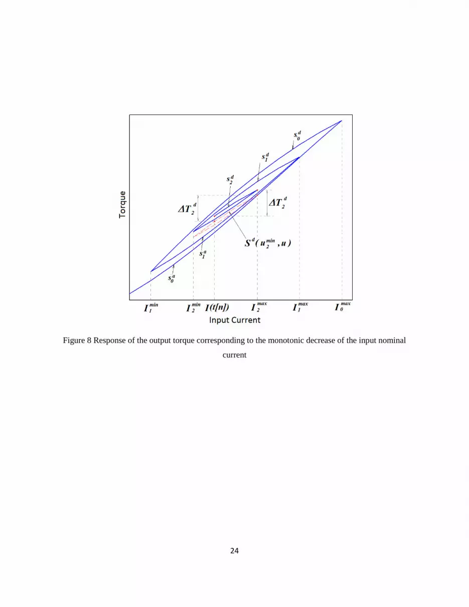
Consider the monotonic decrease of input excitation case with input excitation and corresponding output
torque as shown in figures 7 and 8. In these figures, 0
as is the main ascending; 1
ds and 2
ds stand
respectively for the first and second-order descending segments. The output torque at the
instantaneousness [ ]t n is expressed as follows:
max
2 2( [ ]) ( )ex
d
nT I t T I T (13)

8
where 2
dT is the difference between the torque at the instantaneousness [ ]t n and max
2t when the
response follows on the segment 2
ds . This term can also be obtained indirectly based on this first-order
curve as follows:
max max max
2 2 2 2( , ) ( , [ ]).d d
n
dT S I I S I I t (14)
By substituting equation (14) into equation (13), the expression of the output torque is expressed in detail
in the following form.
max max max max
2 2 2 2( [ ]) ( ) ( , [ ]) ( , ).d d
n ex nT I t T I S I I t S I I (15)
Similarly, the generalized form of the output displacement while considering the m th order descending
segment can be expressed as
max max max max( [ ]) ( ) ( , [ ]) ( , ).n ex
d d
m m m mnT I t T I S I I t S I I (16)
In summary, equation (12) and equation (16) constitute the approach to modeling the BMR actuator
considering hysteresis in the cases of input monotonic increase and monotonic decrease of the nominal
current, respectively. In order to employ the expressions for hysteresis (12) and (16), two data sets of the
discretized first-order ascending and descending curves ( , )a
iS I I , ( , )d
iS I I must be determined in
advance. If the segments min( , )a
mS I I and max( , )d
mS I I in equations (12) and (16) are not coincident with
the discretized ones in the datasets, the interpolation method, which was proposed in [17], can be adopted
to obtain the values of these segments.
3.2 Inversed CBH model for BMR actuator
The output torque of a BMR actuator versus the input nominal current can be simply symbolized in
following form.
( [ ]) [ ( [ ])]T t n H I t n (17)
In the reverse sense, the necessary applied nominal current to obtain a desired torque can be expressed as
1( [ ]) [ ( [ ])]I t n H T t n (18)
where 1[ ]H
is the inverse hysteretic operator. Consequently, high precise control can be achieved if
there exists an inverse hysteretic operator 1[ ]H
such that the composition of [ ]H and 1[ ]H
drives
the actuator to follow the desired torque. The inverse model for the compensator in this work is assumed
9
to be the hysteretic operator that possesses the same properties as that of the CBH model. It implies that
this model also owns the wiped-out, loop closing between the consecutive control points and congruency,
from which the CBH model is developed. Therefore, similarly, with a torque considered as the input
applied to an inverse hysteresis model, the necessary driving current can be expressed by modifying
equations (12) and (16) slightly as in the following forms:
min min min min( [ ]) ( ) ( , [ ]) ( , ),d
a a
m m m mn ex nI T t I T I T T t I T T (19)
max max max max( [ ]) ( ) ( , [ ]) ( , ).d
d d
m m m mn ex nI T t I T I T T t I T T (20)
In the above equations, the terms min( , [ ])a
m nI T T t and min min( , )a
m mI T T stand for the values of the segment
min( , )a
mI T T at desired [ ]nT t and min
mT respectively; max( , [ ])d
m nI T T t and max max( , )d
m mI T T are the values
of the segment max( , )d
mI T T at [ ]nT t and max
mT respectively. Similarly, the interpolation method in [17]
can be adopted to obtain the segments min( , )a
mI T T and max( , )d
mI T T in the case they are not coincident
with the database sets of first order ascending and descending current segments.
4. Experimental Results and Discussions
A setup for the experiment is shown in figure 9. The apparatus consists of the BMR actuator with its
driving system, a data acquisition board SCB68 and a PXI controller of National Instrument corporation.
In addition, a 6-DOF force sensor Nano 17 is used to measure the output signal. It is remarkable that the
longitudinal force is measured instead of the torque via a lever as shown in figure 10. Subsequently, the
output torque can be induced easily. Moreover, because the control signals from the PXI system are
voltages 1 2,u u while the coils need the current sources, several current voltage-current converters are
utilized. These converters have a converting coefficient 0.125. It means that 1V of control voltage is
converted to 0.125A of current. As mentioned above, the actuating torque of the BMR actuator comes
from the effects of the magnetic field-induced and dry friction shear stresses. The contributor due to dry
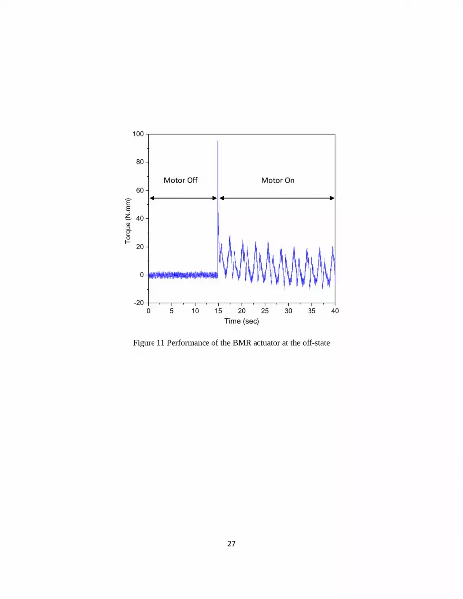
friction exists because of the imperfect of manufacturing and assembly as well as sealing. Figure 11
shows a performance of the BMR actuator at zero current before and after motor running. Because there
is no magnetic field, the torque is completely occurred from the effect of dry friction. It is not constant but
varying periodically in a revolution of the rotors of the actuator. In order to obtain the magnetic field
induced torque, the dry friction component should be identified and excluded from the measured torque of
the BMR actuator. To identify the friction torque, an incremental encoder system including a disk and
10
three photodiode is inserted at the linking position between driving system and the actuator as shown in
figure 10. Thank to this encoder system, the variation of the friction torque in one revolution can be
identified successfully. The form of the friction torque is proposed as follows:
2 3 4 71 5 6sin( ) sin(2 ) sin(3 )fT f f f f f f f (21)
Where, is the angular position of the rotors; 1 7,...f f are the coefficients which are identified via
experimental data and optimization. To obtain these coefficients, a minimization of the following cost
function is carried out.
2
1
( ) ( )ex
N
k
fJ T k T k
(22)
where, ( )exT k is the measured torque value at zero current at the time k . Figure 12 shows the identified
friction torque and corresponding experimental data. It is observable that the identified friction torque
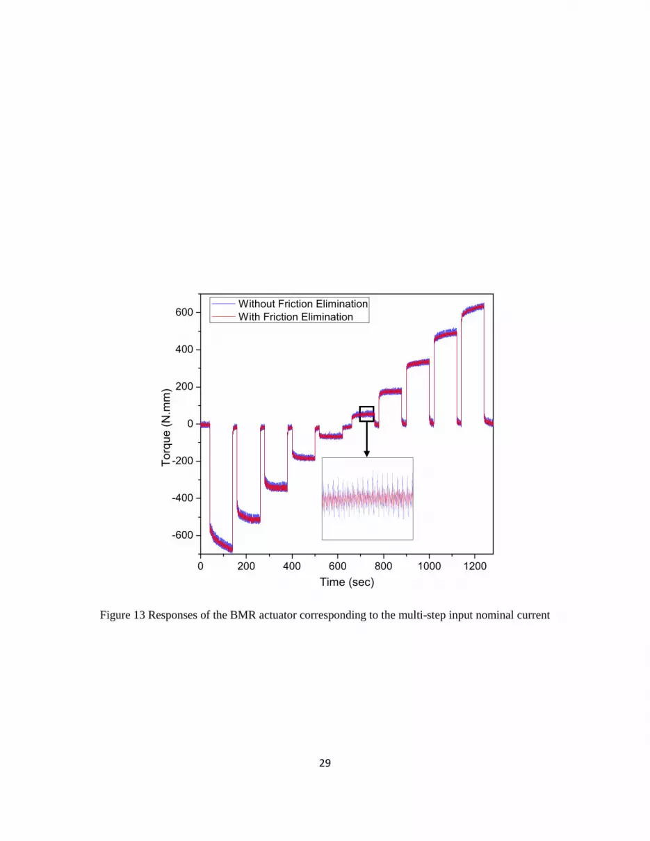
agrees well with experimental data. In order to assess the effectiveness of excluding the effect of the
friction torque from the performance of the actuator’s torque, an experiment with applied multi-step of
input current is carried out. Figure 13 shows the performance of the actuator with and without excluding
the effect of friction. It is realized that the signal becomes smoother. Moreover, the friction torque
generated in the actuator is almost independent with the stimulus of the input current. After that, in order
to model and control the BMR actuator, two datasets of first order curves ( , )a
iI T T and ( , )d
iI T T need to
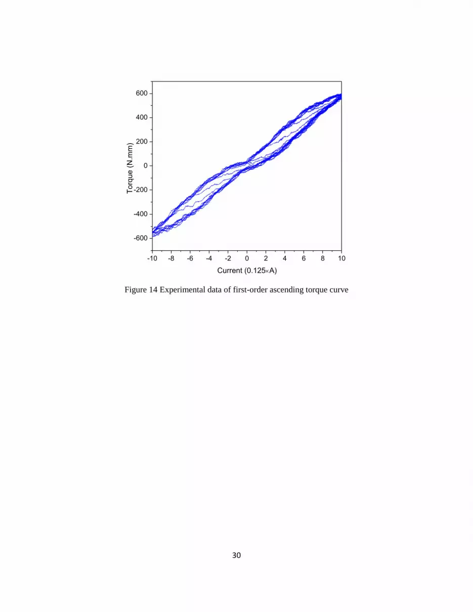
be obtained in advance. The procedure to identify them was given in detail in [17]. First, two
experimental data of first-order ascending and descending torque curves after excluding the effect of
friction are obtained as shown in figures 14 and 15. From these data, two dataset of first-order ascending
and descending current curves are achieved using curve fitting method and shown in figures 16 and 17.
In order to evaluate the effectiveness of the proposed model and corresponding compensator, several
experiments are carried out. First of all, an experiment for compensation for the friction is carried out. In
this experiment, the hysteresis effect is not taken account. Consequently, relationship between the current
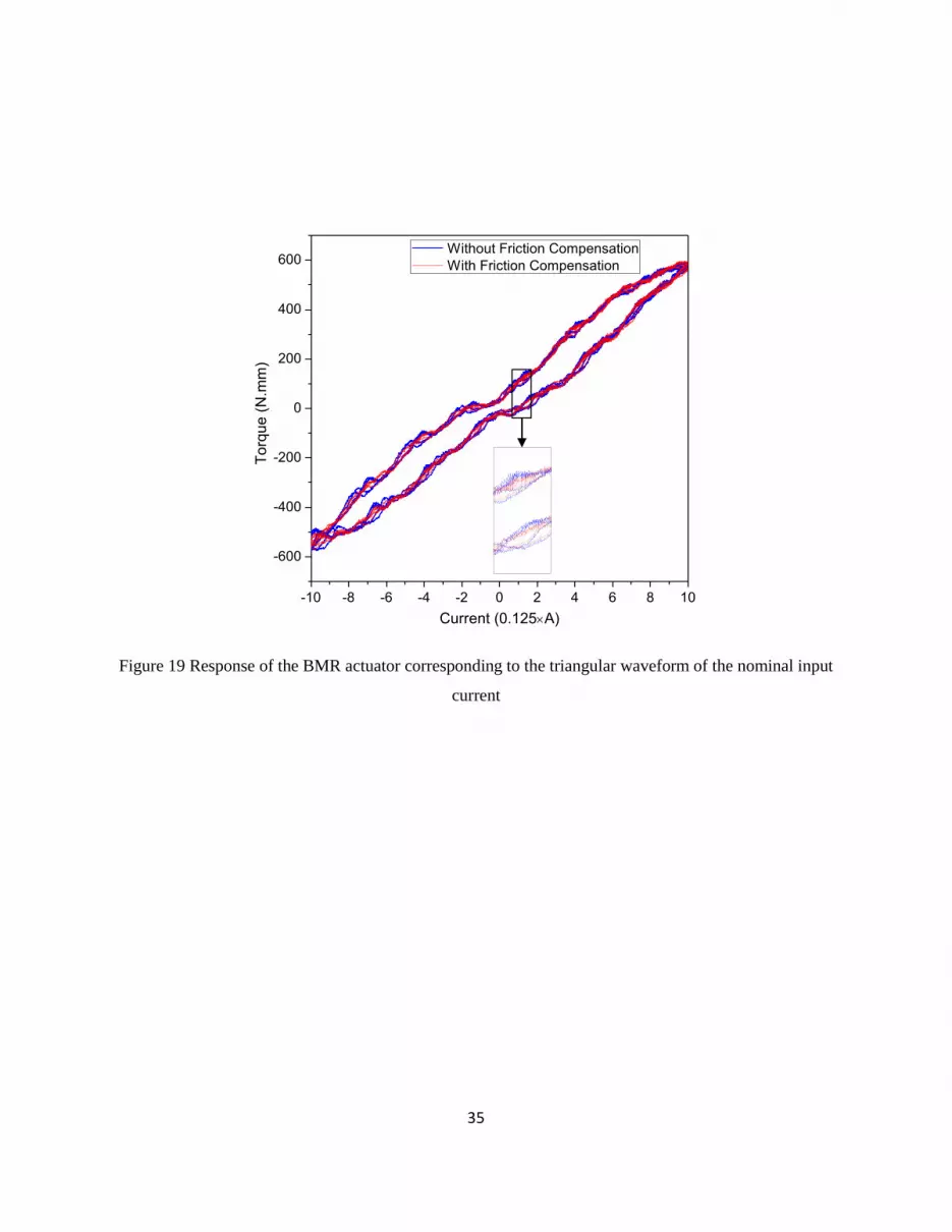
and the torque is assumed to be linear. Figure 18 shows a triangle waveform of a nominal input current. It
is noteworthy to remind that the actual currents to two coils are equivalent to the positive and negative
values of the nominal one, respectively. Figure 19 shows two responses in the cases of with and without
friction compensation. It is observable that the response with friction compensation is smoother, the
fluctuation amplitude is smaller. Or in other word, its quality becomes better that that without considering
the effect of friction. It is also noted that the effect of hysteresis is significant in both responses. It is
reasonable because the effect of hysteresis is not considered in this experiment.

11
The accuracy of the hysteresis model and its compensation is analyzed in an open-loop tracking control
experiment. In this experiment, a triangular waveform is applied as a reference to the hysteresis
compensator. Based on the formulations shown in section 2, the compensator produces a proper control
signal to BMR actuator via a voltage-current converter. The block diagram for the open-loop control in
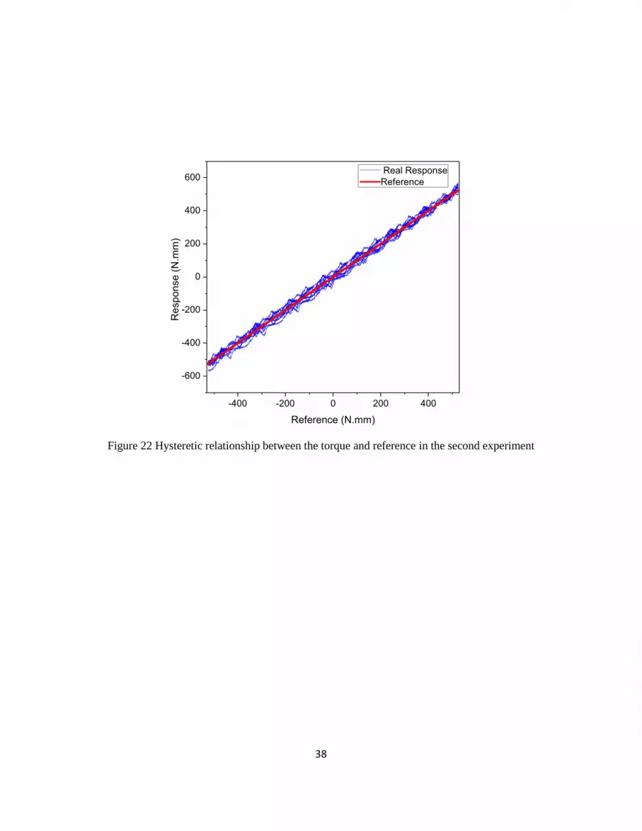
this experiment is shown in figure 20. Figure 21 shows the shape of the reference as well as the real
response. It is realized from the result shown in that the actual response matches well with reference.
Figure 22 shows that the hysteresis effect is almost eliminated although the fluctuation of the response is
significant because the effect of friction is not taken account in this experiment.
At last, an open-loop torque tracking control experiment considering both hysteresis and friction effects is
carried out with a random multi-peak reference. The block diagram for the control is shown in figure 23.
As shown in the figure, the control voltage is a summation of two compensations from hysteresis and
friction effects. The performances of the open-loop control of the BMR brake demonstrated in figure 24
show that the quality of the response with both friction and hysteresis compensations is better in
comparison with that without considering the friction effect. Figure 25 shows clearly that the error of the
response with both compensations is smoother. Moreover, it is smoother compared to that without friction
compensation.
5. Conclusions
In this work, a novel kind of MR actuators called BMR actuator was presented and accurate control
responses of the BMR were experimentally investigated. The BMR actuator consists of two rotor rotating
counter to each other. With such a configuration, it can work as either a clutch or brake. Or in other
words, it can generate either a repulsive or resistance torque. In order to transmit successfully two counter
rotations to the rotors of the BMR actuator, a motor and corresponding driving gear system was also
presented. After that, an approach to model the BMR actuator considering the effect of hysteresis was
proposed. In our work, the CBH model, which was applied successfully in modeling and control of a
piezoelectric actuator, was adopted. Subsequently, from the hysteresis model, a compensator was
developed. In addition, because it is necessary to use seals to prevent leakage of MR fluid in the BMR
actuator, the existence of the dry friction is unavoidable. More seriously, due to the imperfect of the
manufacturing process, the generated friction torque is not constant and tends to fluctuate periodically.
Consequently, in order to obtain accurately the reference datasets for the CBH model, this friction effect
must be identified and excluded. In our work, a sinusoidal form of friction torque was proposed. Its
parameters were obtained via an identification process with the objective to minimize a least square cost

12
function. In order to evaluate the performance of the hysteresis model and its compensator, several
experiments were undertaken. The results obtained from these experiments revealed that the CBH model
and its corresponding compensator can be applied successfully to modeling a BMR actuator. Moreover,
the proposed sinusoidal model of friction torque is enough efficient to catch well the friction effect. As
well known, due to wide range of generated torque (from negative to positive), the BMR actuator has a
good potential as a multi-function device and can be integrated in medical haptic systems where sensing
force from a patient body might be a resistance or repulsion. It is finally remarked that as a second step of
this research work the proposed BMR will be utilized to make a medical haptic device which can be
integrated with a slave robot system for minimally invasive surgery.
Acknowledgement
This work was supported by Inha University Research Grant and the National Research Foundation of
Korea (NRF) grant funded by the Korea Government (MEST) (No. 2012-0005613).
13
References
[1]RAKHEJA S, SU H and SANKAR T S 1990 Analysis of a Passive Sequential Hydraulic Damper for
Vehicle Suspension Vehicle System Dynamics: International Journal of Vehicle Mechanics and Mobility
19 289-312
[2]Lee H S and Choi S B 2000 Control and response characteristics of a magneto-rheological fluid
damper for passenger vehicles J Intel Mat Syst Str 11 80-7
[3]Niwa N, Kobori T, Takahashi M, Midorikawa H, Kurata N and Mizuno T 2000 Dynamic loading test
and simulation analysis of full-scale semi-active hydraulic damper for structural control Earthquake Eng
Struc 29 789-812
[4]Kurata N, Kobori T, Takahashi M, Ishibashi T, Niwa N, Tagami J and Midorikawa H 2000 Forced
vibration test of a building with semi-active damper system Earthquake Eng Struc 29 629-45
[5]Huang J, Zhang J Q, Yang Y and Wei Y Q 2002 Analysis and design of a cylindrical magneto-
rheological fluid brake J Mater Process Tech 129 559-62
[6]Nguyen Q H, Choi S B, Lee Y S and Han M S 2009 An analytical method for optimal design of MR
valve structures Smart Mater Struct 18
[7] Stanway R 2004 Smart fluids: current and future developments Mater Sci Tech-Lond 20 931-9
[8]Li W H and Du H 2003 Design and experimental evaluation of a magnetorheological brake Int J Adv
Manuf Tech 21 508-15
[9]Lee U, Kim D, Hur N and Jeon D 1999 Design analysis and experimental evaluation of an MR fluid
clutch J Intel Mat Syst Str 10 701-7
[10]Saito T and Ikeda H 2007 Development of normally closed type of magnetorheological clutch and its
application to safe torque control system of human-collaborative robot J Intel Mat Syst Str 18 1181-5
[11]Liu B, Li W H, Kosasih P B and Zhang X Z 2006 Development of an MR-brake-based haptic device
Smart Mater Struct 15 1960-6
[12]Blake J and Gurocak H B 2009 Haptic Glove With MR Brakes for Virtual Reality Ieee-Asme T Mech
14 606-15
[13]Ohnishi K, Shimono T and Natori K 2009 Haptics for medical applications Artificial Life and
Robotics 13 383-9
14
[14]Rosen J, Hannaford B and Satava R M 2011 Surgical Robotics: Systems, Applications, and Visions:
Springer)
[15]Okamura A M 2009 Haptic feedback in robot-assisted minimally invasive surgery Curr Opin Urol 19
102-7
[16]Nguyen P B and Choi S B 2012 Compensator design for hysteresis of a stacked PZT actuator using a
congruency-based hysteresis model Smart Mater Struct 21
[17]Nguyen P B and Choi S B 2011 A novel rate-independent hysteresis model of a piezostack actuator
using the congruency property Smart Mater Struct 20
15
Captions for Tables and Figures
Figure 1 Configuration of the BMR actuator
Figure 2 BMR actuator and its driving gear system
Figure 3 Magnetic field in the BMR actuator
Figure 4 Monotonic increase of the input nominal current
Figure 5 Response of the output torque corresponding to the monotonic increase of the input
nominal current
Figure 6 Demonstration of the first-order ascending curve congruent with the higher order one
Figure 7 Monotonic decrease of the input nominal current
Figure 8 Response of the output torque corresponding to the monotonic decrease of the input
nominal current
Figure 9 Apparatus for the experimental setup
Figure 10 Close View of the BMR cctuator
Figure 11 Performance of the BMR actuator at the off-state
Figure 12 Experimental and corresponding identified torque at off-state
Figure 13 Responses of the BMR actuator corresponding to the multi-step input nominal current
Figure 14 Experimental data of first-order ascending torque curve
Figure 15 Experimental data of first-order descending torque curve
Figure 16 Dataset of first-order ascending current curves obtained using curve fitting
Figure 17 Dataset of first-order descending current curves obtained using curve fitting
Figure 18 Triangular waveform of the nominal input current
Figure 19 Response of the BMR actuator corresponding to the triangular waveform of the nominal
input current
Figure 20 Block diagram for open-loop control considering hysteresis
Figure 21 Torque responses of the BMR actuator with triangular waveform of reference
Figure 22 Hysteretic relationship between the torque and reference in the second experiment

16
Figure 23 Block diagram for open-loop control considering both hysteresis and friction effects.
Figure 24 Performance of the proposed compensator with a random multi-peak reference
Figure 25 Error of the proposed compensator in comparison with the reference

17
Figure 1 Configuration of the BMR actuator
Coil Holder
MR Fluid
Shaft 1
Shaft 2
Casing’s
Shaft
Rotor 1 Rotor 2
Coil 1 Coil 2
Casing
Non-Magnetic Partition

18
Figure 2 BMR actuator and its driving gear system

19
Figure 3 Magnetic field in the BMR actuator
Coil 1 Coil 2
Magnetic Field

20
Figure 4 Monotonic increase of the input nominal current

21
Figure 5 Response of the output torque corresponding to the monotonic increase of the input nominal
current

22
Figure 6 Demonstration of the first-order ascending curve congruent with the higher order one

23
Figure 7 Monotonic decrease of the input nominal current
24
Figure 8 Response of the output torque corresponding to the monotonic decrease of the input nominal
current

25
Figure 9 Apparatus for the experimental setup
Voltage-Current
Converter
BMR Actuator
Angular
Position
Control
Voltage
Control
Current
PXI system

26
Figure 10 Close view of the BMR actuator
Lever
Rotary Disk
Photodiode
Force Sensor
Nano 17
(a) Front View
(b) Side View
27
Figure 11 Performance of the BMR actuator at the off-state
0 5 10 15 20 25 30 35 40
-20
0
20
40
60
80
100
To
rqu
e (
N.m
m)
Time (sec)
Motor Off Motor On

28
0 45 90 135 180 225 270 315 360
-20
-10
0
10
20
30
40
50
Experimental Torque
Identified TorqueT
orq
ue (
N.m
m)
Angular Position (deg)
Figure 12 Experimental and corresponding identified torque at off-state
29
Figure 13 Responses of the BMR actuator corresponding to the multi-step input nominal current
0 200 400 600 800 1000 1200
-600
-400
-200
0
200
400
600
Torq
ue (
N.m
m)
Time (sec)
Without Friction Elimination
With Friction Elimination
30
-10 -8 -6 -4 -2 0 2 4 6 8 10
-600
-400
-200
0
200
400
600
To
rque
(N
.mm
)
Current (0.125A)
Figure 14 Experimental data of first-order ascending torque curve

31
-10 -8 -6 -4 -2 0 2 4 6 8 10
-600
-400
-200
0
200
400
600
To
rque
(N
.mm
)
Current (0.125A)
Figure 15 Experimental data of first-order descending torque curve

32
-600 -400 -200 0 200 400 600
-10
-8
-6
-4
-2
0
2
4
6
8
10
Cu
rre
nt
(0.1
25A
)
Torque (N.mm)
Figure 16 Dataset of first-order ascending current curves obtained using curve fitting

33
-600 -400 -200 0 200 400 600
-10
-8
-6
-4
-2
0
2
4
6
8
10
Cu
rre
nt
(0.1
25A
)
Torque (N.mm)
Figure 17 Dataset of first-order descending current curves obtained using curve fitting

34
0 50 100 150 200
-10
-5
0
5
10
Inpu
t N
om
inal C
urr
ent
(0.1
25A
)
Data (sec)
Figure 18 Triangular waveform of the nominal input current
35
Figure 19 Response of the BMR actuator corresponding to the triangular waveform of the nominal input
current
-10 -8 -6 -4 -2 0 2 4 6 8 10
-600
-400
-200
0
200
400
600
To
rque
(N
.mm
)
Current (0.125A)
Without Friction Compensation
With Friction Compensation

36
Figure 20 Block diagram for open-loop control considering hysteresis
1 2,I I
Currents
T 1 2,u u
Voltages
dT
Desired
Torque
Actual Torque
Hysteresis
Compensator
1[ ]H
K
Voltage-Current
Converter
BMR Actuator

37
0 50 100 150 200
-600
-400
-200
0
200
400
600
To
rque
(N
.mm
)
Time (sec)
Real Response
Reference
Figure 21 Torque responses of the BMR actuator with triangular waveform of reference
38
-400 -200 0 200 400
-600
-400
-200
0
200
400
600
Re
sp
on
se
(N
.mm
)
Reference (N.mm)
Real Response
Reference
Figure 22 Hysteretic relationship between the torque and reference in the second experiment

39
Figure 23 Block diagram for open-loop control considering both hysteresis and friction effects.
1 2,I I
Currents
Angular
Position
T 1 2,u u
Voltages
dT
Desired
Torque
Actual Torque
Hysteresis
Compensator1[ ]H
K
Voltage-Current
Converter
BMR Actuator
Encoder Friction
Compensator

40
0 50 100 150 200
-600
-400
-200
0
200
400
600
T
orq
ue
(N
.mm
)
Time (sec)
With Friction Compensation
Without Friction Compensation
Reference
Figure 24 Performance of the proposed compensator with a random multi-peak reference

41
0 50 100 150 200
-60
-40
-20
0
20
40
60
Err
or
(N.m
m)
Time (sec)
Without Friction Compensation
With Friction Compensation
Figure 25 Error of the proposed compensator in comparison with the reference


