Embed Size (px)
Citation preview
5
ABB catalogue | 1SDC200006D0209 | 5/1
Accessories
Functions of the accessories 5/2
Accessories supplied as standard 5/3
Accessories supplied on request 5/4
Shunt opening and closing release 5/6
Undervoltage release 5/8
Geared motor for the automatic charging of closing springs 5/10
Signalling of overcurrent release tripped 5/11
Auxiliary contacts 5/12
Transformers and operation counters 5/15
Mechanical safety locks 5/16
Transparent protective covers 5/18
Interlock between circuit-breakers 5/19
Automatic transfer switches - ATS021 and ATS022 5/22
Spare parts and Retrofitting 5/24
5
5/2 | ABB catalogue | 1SDC200006D0209
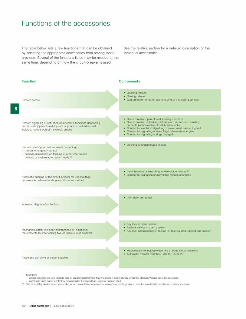
Functions of the accessories
The table below lists a few functions that can be obtained
by selecting the appropriate accessories from among those
provided. Several of the functions listed may be needed at the
same time, depending on how the circuit-breaker is used.
Function Components
Automatic opening of the circuit-breaker for undervoltage
(for example, when operating asynchronous motors)
• Opening release
• Closing release
• Geared motor for automatic charging of the closing springs
• Circuit-breaker open-closed auxiliary contacts
• Circuit-breaker racked-in, test isolated, racked-out auxiliary
contacts (withdrawable circuit-breaker only)
• Contact for electrical signalling of overcurrent release tripped
• Contact for signalling undervoltage release de-energized
• Contact for signalling springs charged
• Opening or undervoltage release
• Instantaneous or time delay undervoltage release (2)
• Contact for signalling undervoltage release energized
• Mechanical interlock between two or three circuit-breakers
• Automatic transfer switches - ATS021-ATS022
• Key lock in open position
• Padlock device in open position
• Key lock and padlocks in racked-in, test isolated, racked-out position
Remote control
Remote signalling or actuation of automatic functions depending
on the state (open-closed-tripped) or position (racked-in, test
isolated, racked-out) of the circuit-breaker.
Mechanical safety locks for maintenance or functional
requirements for interlocking two or more circuit-breakers
Automatic switching of power supplies
Increased degree of protection
Remote opening for various needs, including:
– manual emergency control
– opening dependent on tripping of other interruption
devices or system automation needs (1).
• IP54 door protection
(1) Examples:
– circuit-breakers on Low Voltage side of parallel transformers that must open automatically when the Medium Voltage side device opens.
– automatic opening for control by external relay (undervoltage, residual current, etc.).
(2) The time-delay device is recommended when unwanted operation due to temporary voltage drops, is to be avoided (for functional or safety reasons).
See the relative section for a detailed description of the
individual accessories.
5
ABB catalogue | 1SDC200006D0209 | 5/3
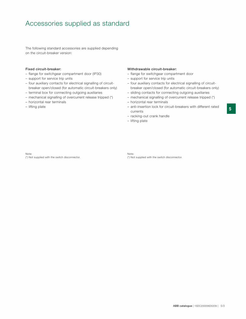
Accessories supplied as standard
Fixed circuit-breaker:– flange for switchgear compartment door (IP30)
– support for service trip units
– four auxiliary contacts for electrical signalling of circuit-
breaker open/closed (for automatic circuit-breakers only)
– terminal box for connecting outgoing auxiliaries
– mechanical signalling of overcurrent release tripped (*)
– horizontal rear terminals
– lifting plate
The following standard accessories are supplied depending
on the circuit-breaker version:
Withdrawable circuit-breaker:– flange for switchgear compartment door
– support for service trip units
– four auxiliary contacts for electrical signalling of circuit-
breaker open/closed (for automatic circuit-breakers only)
– sliding contacts for connecting outgoing auxiliaries
– mechanical signalling of overcurrent release tripped (*)
– horizontal rear terminals
– anti-insertion lock for circuit-breakers with different rated
currents
– racking-out crank handle
– lifting plate
Note:
(*) Not supplied with the switch disconnector.
Note:
(*) Not supplied with the switch disconnector.
5
5/4 | ABB catalogue | 1SDC200006D0209
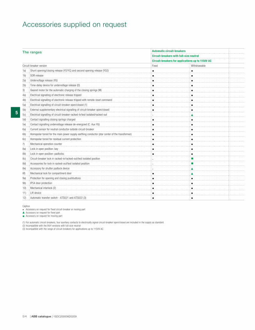
The ranges Automatic circuit-breakers
Circuit-breakers with full-size neutral
Circuit-breakers for applications up to 1150V AC
Circuit-breaker version Fixed Withdrawable
1a) Shunt opening/closing release (YO/YC) and second opening release (YO2) • •1b) SOR release • •2a) Undervoltage release (YU) • •2b) Time-delay device for undervoltage release (D) • •3) Geared motor for the automatic charging of the closing springs (M) • •4a) Electrical signalling of electronic release tripped • •4b) Electrical signalling of electronic release tripped with remote reset command • •5a) Electrical signalling of circuit-breaker open/closed (1) • •5b) External supplementary electrical signalling of circuit-breaker open/closed • •5c) Electrical signalling of circuit-breaker racked-in/test isolated/racked-out -5d) Contact signalling closing springs charged • •5e) Contact signalling undervoltage release de-energized (C. Aux YU) • •6a) Current sensor for neutral conductor outside circuit-breaker • •6b) Homopolar toroid for the main power supply earthing conductor (star center of the transformer) • •6c) Homopolar toroid for residual current protection • •7) Mechanical operation counter • •8a) Lock in open position: key • •8b) Lock in open position: padlocks • •8c) Circuit-breaker lock in racked-in/racked-out/test isolated position -8d) Accessories for lock in racked-out/test isolated position -8e) Accessory for shutter padlock device -8f) Mechanical lock for compartment door •9a) Protection for opening and closing pushbuttons • •9b) IP54 door protection • •10) Mechanical interlock (2) • •11) Lift device • •12) Automatic transfer switch - ATS021 and ATS022 (3) • •
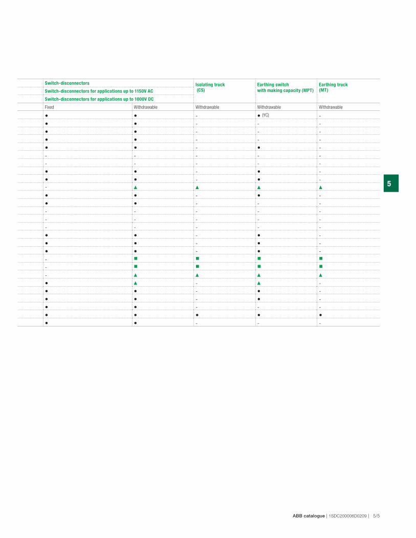
Accessories supplied on request
Caption
• Accessory on request for fixed circuit-breaker or moving part
Accessory on request for fixed part
Accessory on request for moving part
(1) For automatic circuit-breakers, four auxiliary contacts to electrically signal circuit-breaker open/closed are included in the supply as standard.
(2) Incompatible with the E6/f versions with full-size neutral
(3) Incompatible with the range of circuit-breakers for applications up to 1150V AC
5
ABB catalogue | 1SDC200006D0209 | 5/5
Switch-disconnectors Isolating truck
(CS)
Earthing switch
with making capacity (MPT)
Earthing truck
(MT)Switch-disconnectors for applications up to 1150V AC
Switch-disconnectors for applications up to 1000V DC
Fixed Withdrawable Withdrawable Withdrawable Withdrawable
• • - • (YC) -
• • - - -
• • - - -
• • - - -
• • - • -
- - - - -
- - - - -
• • - • -
• • - • -
-
• • - • -
• • - - -
- - - - -
- - - - -
- - - - -
• • - • -
• • - • -
• • - • -
-
-
-
• - -
• • - • -
• • - • -
• • - - -
• • • • •
• • - - -
1S
DC
20
01
31
F0
00
1
1S
DC
20
01
32
F0
00
1
1S
DC
20
01
33
F0
00
11
SD
C2
00
13
4F
00
01
5
5/6 | ABB catalogue | 1SDC200006D0209
Shunt opening and closing release
(1) The minimum impulse current duration time in instantaneous service must be
100 ms
(2) If the opening release is permanently connected to the power supply, wait at
least 30 ms before sending the command to the shunt closing release.
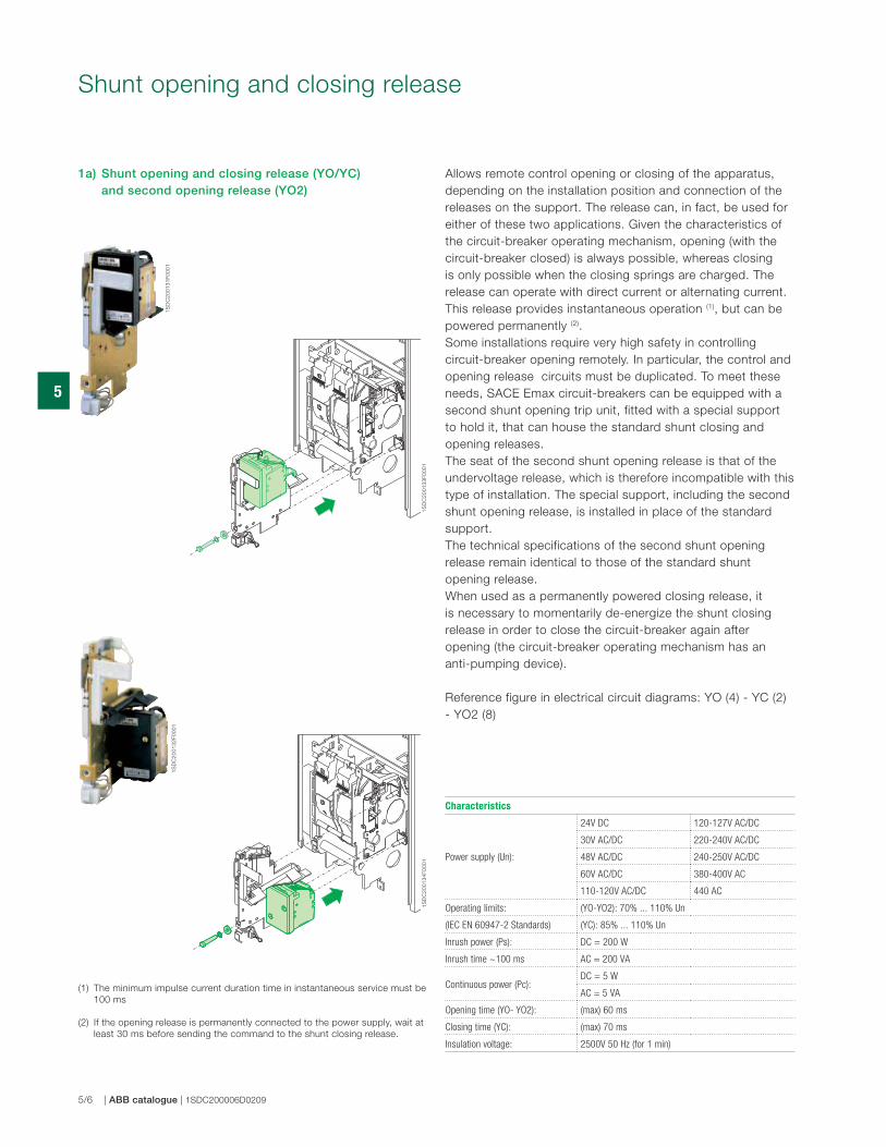
1a) Shunt opening and closing release (YO/YC) and second opening release (YO2)
Allows remote control opening or closing of the apparatus,
depending on the installation position and connection of the
releases on the support. The release can, in fact, be used for
either of these two applications. Given the characteristics of
the circuit-breaker operating mechanism, opening (with the
circuit-breaker closed) is always possible, whereas closing
is only possible when the closing springs are charged. The
release can operate with direct current or alternating current.
This release provides instantaneous operation (1), but can be
powered permanently (2).
Some installations require very high safety in controlling
circuit-breaker opening remotely. In particular, the control and
opening release circuits must be duplicated. To meet these
needs, SACE Emax circuit-breakers can be equipped with a
second shunt opening trip unit, fitted with a special support
to hold it, that can house the standard shunt closing and
opening releases.
The seat of the second shunt opening release is that of the
undervoltage release, which is therefore incompatible with this
type of installation. The special support, including the second
shunt opening release, is installed in place of the standard
support.
The technical specifications of the second shunt opening
release remain identical to those of the standard shunt
opening release.
When used as a permanently powered closing release, it
is necessary to momentarily de-energize the shunt closing
release in order to close the circuit-breaker again after
opening (the circuit-breaker operating mechanism has an
anti-pumping device).
Reference figure in electrical circuit diagrams: YO (4) - YC (2)
- YO2 (8)
Characteristics
Power supply (Un):
24V DC 120-127V AC/DC
30V AC/DC 220-240V AC/DC
48V AC/DC 240-250V AC/DC
60V AC/DC 380-400V AC
110-120V AC/DC 440 AC
Operating limits: (YO-YO2): 70% ... 110% Un
(IEC EN 60947-2 Standards) (YC): 85% ... 110% Un
Inrush power (Ps): DC = 200 W
Inrush time ~100 ms AC = 200 VA
Continuous power (Pc):DC = 5 W
AC = 5 VA
Opening time (YO- YO2): (max) 60 ms
Closing time (YC): (max) 70 ms
Insulation voltage: 2500V 50 Hz (for 1 min)
1S
DC
20
01
35
F0
00
1
5
ABB catalogue | 1SDC200006D0209 | 5/7
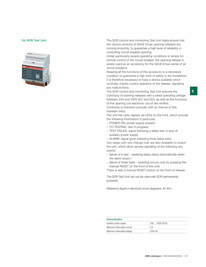
The SOR control and monitoring Test Unit helps ensure that
the various versions of SACE Emax opening releases are
running smoothly, to guarantee a high level of reliability in
controlling circuit-breaker opening.
Under particularly severe operating conditions or simply for
remote control of the circuit-breaker, the opening release is
widely used as an accessory for the SACE Emax series of air
circuit-breakers.
Keeping all the functions of this accessory is a necessary
condition to guarantee a high level of safety in the installation:
it is therefore necessary to have a device available which
cyclically checks correct operation of the release, signalling
any malfunctions.
The SOR control and monitoring Test Unit ensures the
continuity of opening releases with a rated operating voltage
between 24V and 250V (AC and DC), as well as the functions
of the opening coil electronic circuit are verified.
Continuity is checked cyclically with an interval of 20s
between tests.
The unit has optic signals via LEDs on the front, which provide
the following information in particular:
– POWER ON: power supply present
– YO TESTING: test in progress
– TEST FAILED: signal following a failed test or lack of
auxiliary power supply
– ALARM: signal given following three failed tests.
Two relays with one change-over are also available on board
the unit, which allow remote signalling of the following two
events:
– failure of a test - resetting takes place automatically when
the alarm stops )
– failure of three tests - resetting occurs only by pressing the
manual RESET on the front of the unit)
There is also a manual RESET button on the front of release.
The SOR Test Unit can not be used with SOR permanently
powered.
Reference figure in electrical circuit diagrams: AY (61)
1b) SOR Test Unit
Characteristics
Auxiliary power supply 24V ... 250V AC/DC
Maximum interrupted current 6 A
Maximum interrupted voltage 250V AC
1S
DC
20
01
36
F0
00
1
1S
DC
20
01
37
F0
00
1
5
5/8 | ABB catalogue | 1SDC200006D0209
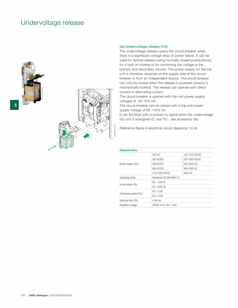
Undervoltage release
2a) Undervoltage release (YU)The undervoltage release opens the circuit-breaker when
there is a significant voltage drop or power failure. It can be
used for remote release (using normally-closed pushbuttons),
for a lock on closing or for monitoring the voltage in the
primary and secondary circuits. The power supply for the trip
unit is therefore obtained on the supply side of the circuit-
breaker or from an independent source. The circuit-breaker
can only be closed when the release is powered (closing is
mechanically locked). The release can operate with direct
current or alternating current.
The circuit-breaker is opened with trip unit power supply
voltages of 35-70% Un.
The circuit-breaker can be closed with a trip unit power
supply voltage of 85-110% Un.
It can be fitted with a contact to signal when the undervoltage
trip unit is energized (C. aux YU - see accessory 5e).
Reference figure in electrical circuit diagrams: YU (6)
Characteristics
Power supply (Un):
24V DC 120-127V AC/DC
30V AC/DC 220-240V AC/DC
48V AC/DC 240-250V AC
60V AC/DC 380-400V AC
110-120V AC/DC 440V AC
Operating limits: Standards CEI EN 60947-2
Inrush power (Ps): DC = 200 W
AC = 200 VA
Continuous power (Pc): DC = 5 W
AC = 5 VA
Opening time (YU): ≤ 80 ms
Insulation voltage: 2500V 50 Hz (for 1 min)
1S
DC
20
01
38
F0
00
1
5
ABB catalogue | 1SDC200006D0209 | 5/9
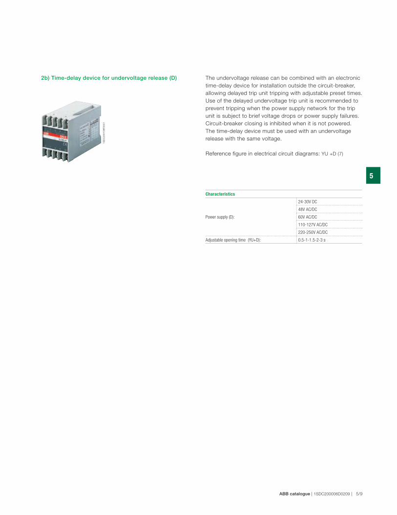
2b) Time-delay device for undervoltage release (D) The undervoltage release can be combined with an electronic
time-delay device for installation outside the circuit-breaker,
allowing delayed trip unit tripping with adjustable preset times.
Use of the delayed undervoltage trip unit is recommended to
prevent tripping when the power supply network for the trip
unit is subject to brief voltage drops or power supply failures.
Circuit-breaker closing is inhibited when it is not powered.
The time-delay device must be used with an undervoltage
release with the same voltage.
Reference figure in electrical circuit diagrams: YU +D (7)
Characteristics
Power supply (D):
24-30V DC
48V AC/DC
60V AC/DC
110-127V AC/DC
220-250V AC/DC
Adjustable opening time (YU+D): 0.5-1-1.5-2-3 s
1S
DC
20
01
39
F0
00
1
1S
DC
20
01
40
F0
00
1
5
5/10 | ABB catalogue | 1SDC200006D0209
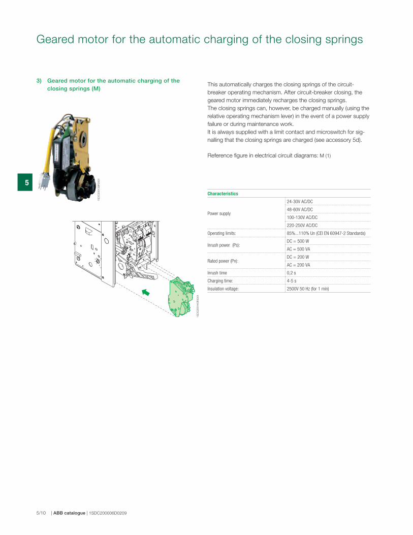
Geared motor for the automatic charging of the closing springs
This automatically charges the closing springs of the circuit-
breaker operating mechanism. After circuit-breaker closing, the
geared motor immediately recharges the closing springs.
The closing springs can, however, be charged manually (using the
relative operating mechanism lever) in the event of a power supply
failure or during maintenance work.
It is always supplied with a limit contact and microswitch for sig-
nalling that the closing springs are charged (see accessory 5d).
Reference figure in electrical circuit diagrams: M (1)
3) Geared motor for the automatic charging of the closing springs (M)
Characteristics
Power supply
24-30V AC/DC
48-60V AC/DC
100-130V AC/DC
220-250V AC/DC
Operating limits: 85%...110% Un (CEI EN 60947-2 Standards)
Inrush power (Ps): DC = 500 W
AC = 500 VA
Rated power (Pn):DC = 200 W
AC = 200 VA
Inrush time 0,2 s
Charging time: 4-5 s
Insulation voltage: 2500V 50 Hz (for 1 min)
1S
DC
20
01
44
F0
00
1
1S
DC
20
01
41
F0
00
1
5
ABB catalogue | 1SDC200006D0209 | 5/11
Signal for overcurrent releases tripped
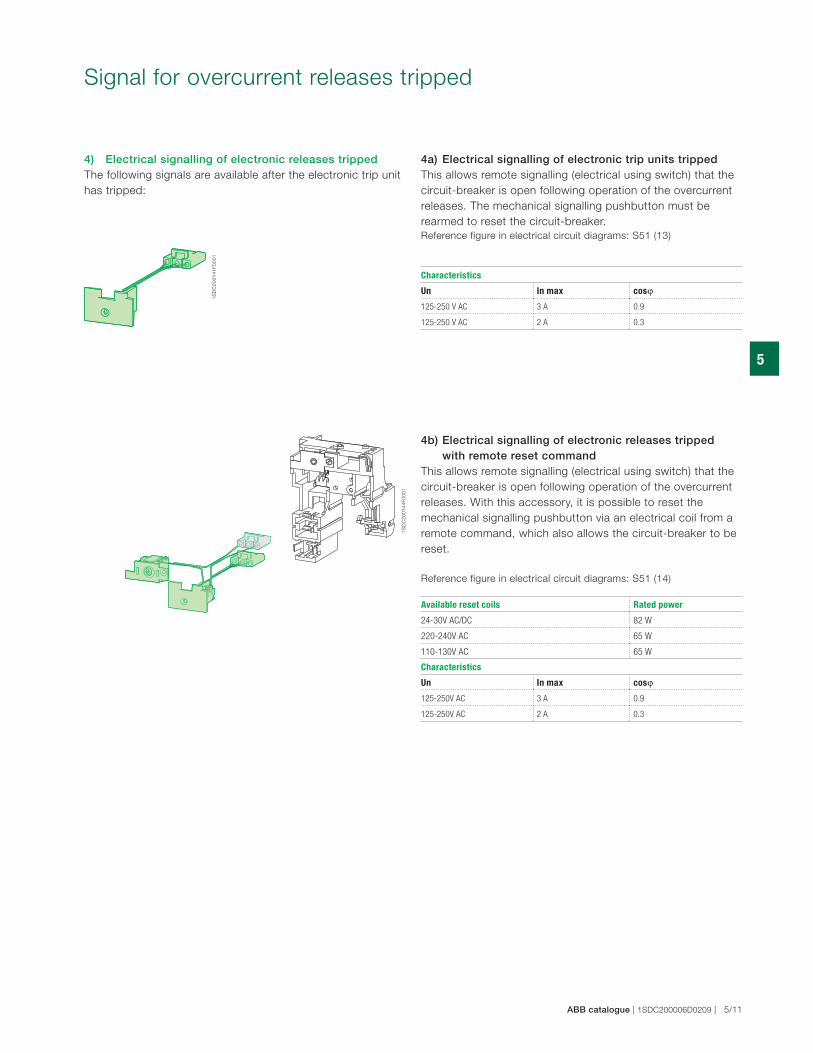
4) Electrical signalling of electronic releases trippedThe following signals are available after the electronic trip unit
has tripped:
4a) Electrical signalling of electronic trip units trippedThis allows remote signalling (electrical using switch) that the
circuit-breaker is open following operation of the overcurrent
releases. The mechanical signalling pushbutton must be
rearmed to reset the circuit-breaker.
Reference figure in electrical circuit diagrams: S51 (13)
4b) Electrical signalling of electronic releases tripped with remote reset commandThis allows remote signalling (electrical using switch) that the
circuit-breaker is open following operation of the overcurrent
releases. With this accessory, it is possible to reset the
mechanical signalling pushbutton via an electrical coil from a
remote command, which also allows the circuit-breaker to be
reset.
Reference figure in electrical circuit diagrams: S51 (14)
Available reset coils Rated power
24-30V AC/DC 82 W
220-240V AC 65 W
110-130V AC 65 W
Characteristics
Un In max cosϕ
125-250V AC 3 A 0.9
125-250V AC 2 A 0.3
Characteristics
Un In max cosϕ
125-250 V AC 3 A 0.9
125-250 V AC 2 A 0.3
1S
DC
20
01
46
F0
00
1
1S
DC
20
01
45
F0
00
1
5
5/12 | ABB catalogue | 1SDC200006D0209
Auxiliary Contacts
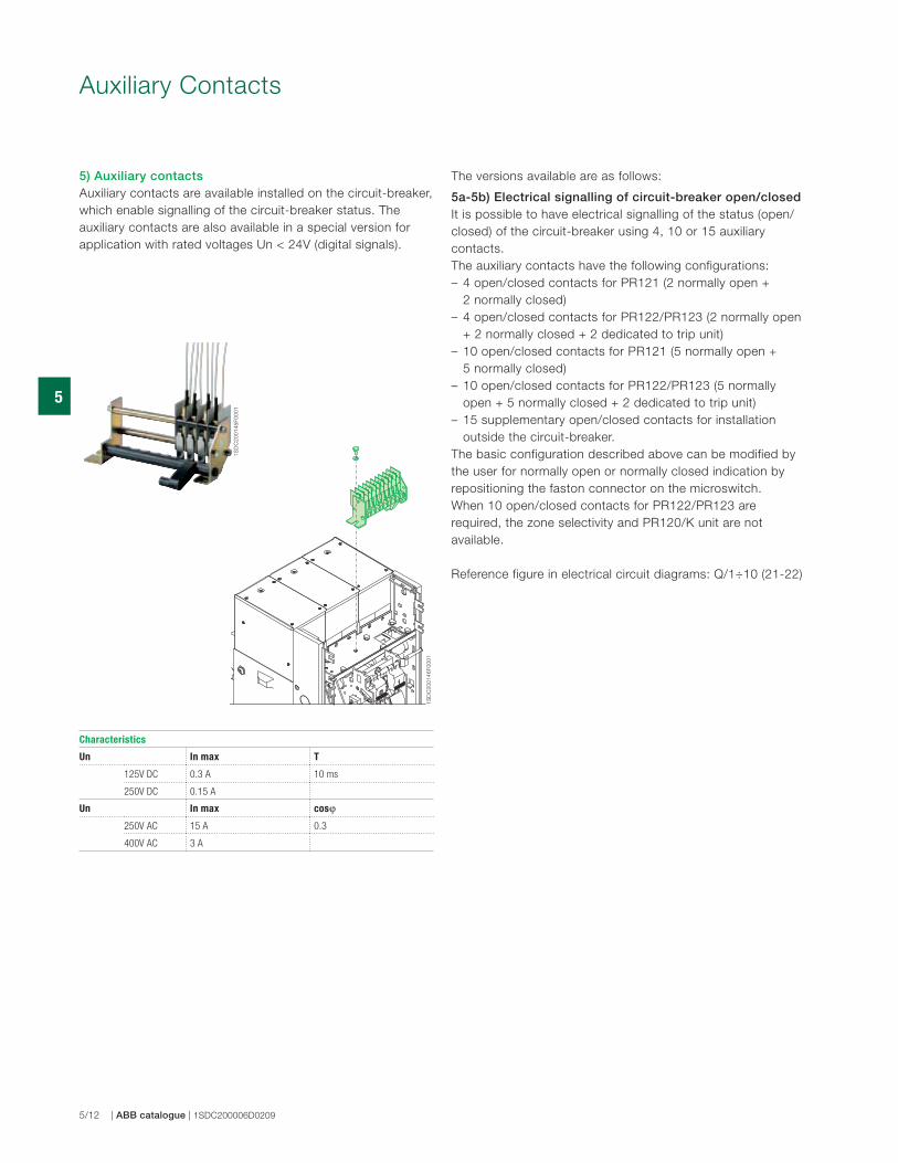
5) Auxiliary contactsAuxiliary contacts are available installed on the circuit-breaker,
which enable signalling of the circuit-breaker status. The
auxiliary contacts are also available in a special version for
application with rated voltages Un < 24V (digital signals).
The versions available are as follows:
5a-5b) Electrical signalling of circuit-breaker open/closedIt is possible to have electrical signalling of the status (open/
closed) of the circuit-breaker using 4, 10 or 15 auxiliary
contacts.
The auxiliary contacts have the following configurations:
– 4 open/closed contacts for PR121 (2 normally open +
2 normally closed)
– 4 open/closed contacts for PR122/PR123 (2 normally open
+ 2 normally closed + 2 dedicated to trip unit)
– 10 open/closed contacts for PR121 (5 normally open +
5 normally closed)
– 10 open/closed contacts for PR122/PR123 (5 normally
open + 5 normally closed + 2 dedicated to trip unit)
– 15 supplementary open/closed contacts for installation
outside the circuit-breaker.
The basic configuration described above can be modified by
the user for normally open or normally closed indication by
repositioning the faston connector on the microswitch.
When 10 open/closed contacts for PR122/PR123 are
required, the zone selectivity and PR120/K unit are not
available.
Reference figure in electrical circuit diagrams: Q/1÷10 (21-22)
Characteristics
Un In max T
125V DC 0.3 A 10 ms
250V DC 0.15 A
Un In max cosϕ
250V AC 15 A 0.3
400V AC 3 A
1S
DC
20
01
47
F0
00
1
1S
DC
20
01
48
F0
00
1
5
ABB catalogue | 1SDC200006D0209 | 5/13
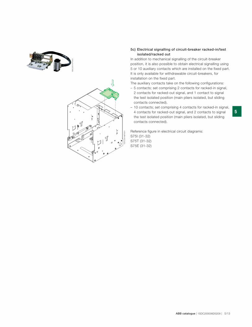
5c) Electrical signalling of circuit-breaker racked-in/test isolated/racked outIn addition to mechanical signalling of the circuit-breaker
position, it is also possible to obtain electrical signalling using
5 or 10 auxiliary contacts which are installed on the fixed part.
It is only available for withdrawable circuit-breakers, for
installation on the fixed part.
The auxiliary contacts take on the following configurations:
– 5 contacts; set comprising 2 contacts for racked-in signal,
2 contacts for racked-out signal, and 1 contact to signal
the test isolated position (main pliers isolated, but sliding
contacts connected).
– 10 contacts; set comprising 4 contacts for racked-in signal,
4 contacts for racked-out signal, and 2 contacts to signal
the test isolated position (main pliers isolated, but sliding
contacts connected).
Reference figure in electrical circuit diagrams:
S75I (31-32)
S75T (31-32)
S75E (31-32)
1S
DC
20
01
49
F0
00
1
1S
DC
20
01
50
F0
00
1
1S
DC
20
01
51
F0
00
1
1S
DC
20
01
52
F0
00
1
5
5/14 | ABB catalogue | 1SDC200006D0209
Auxiliary Contacts
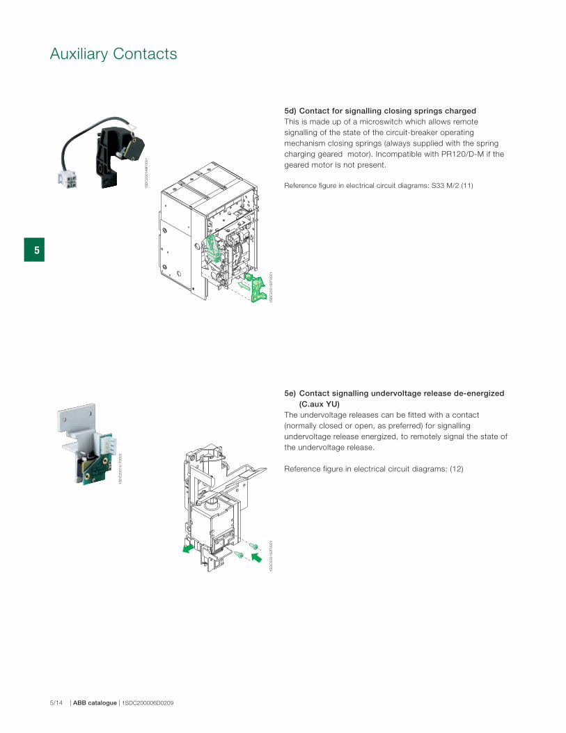
5e) Contact signalling undervoltage release de-energized (C.aux YU)The undervoltage releases can be fitted with a contact
(normally closed or open, as preferred) for signalling
undervoltage release energized, to remotely signal the state of
the undervoltage release.
Reference figure in electrical circuit diagrams: (12)
5d) Contact for signalling closing springs chargedThis is made up of a microswitch which allows remote
signalling of the state of the circuit-breaker operating
mechanism closing springs (always supplied with the spring
charging geared motor). Incompatible with PR120/D-M if the
geared motor is not present.
Reference figure in electrical circuit diagrams: S33 M/2 (11)
1S
DC
20
01
53
F0
00
1
1S
DC
20
01
54
F0
00
1
1S
DC
20
01
55
F0
00
1
1S
DC
20
01
56
F0
00
1
1S
DC
20
06
11
F0
00
1
5
ABB catalogue | 1SDC200006D0209 | 5/15
Transformers and operation counters
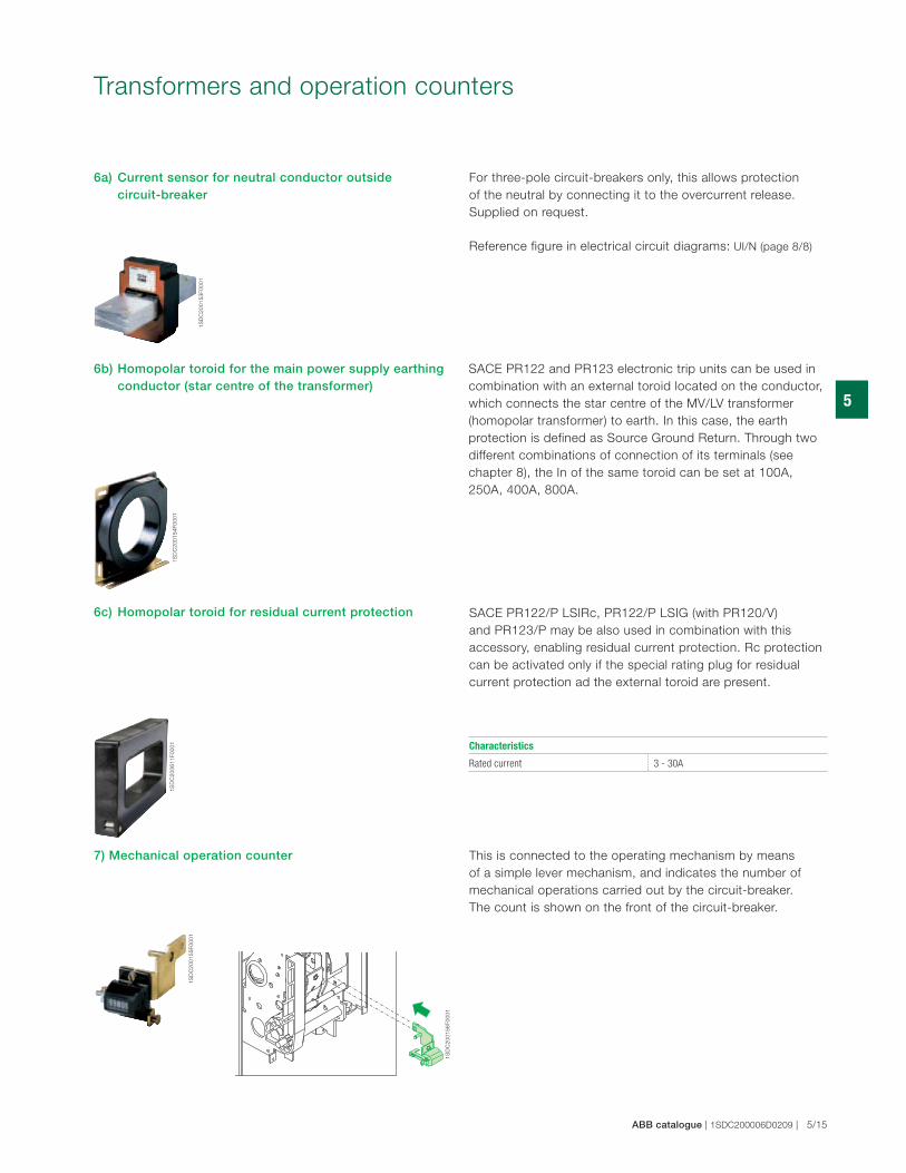
For three-pole circuit-breakers only, this allows protection
of the neutral by connecting it to the overcurrent release.
Supplied on request.
Reference figure in electrical circuit diagrams: UI/N (page 8/8)
SACE PR122 and PR123 electronic trip units can be used in
combination with an external toroid located on the conductor,
which connects the star centre of the MV/LV transformer
(homopolar transformer) to earth. In this case, the earth
protection is defined as Source Ground Return. Through two
different combinations of connection of its terminals (see
chapter 8), the In of the same toroid can be set at 100A,
250A, 400A, 800A.
This is connected to the operating mechanism by means
of a simple lever mechanism, and indicates the number of
mechanical operations carried out by the circuit-breaker.
The count is shown on the front of the circuit-breaker.
SACE PR122/P LSIRc, PR122/P LSIG (with PR120/V)
and PR123/P may be also used in combination with this
accessory, enabling residual current protection. Rc protection
can be activated only if the special rating plug for residual
current protection ad the external toroid are present.
6a) Current sensor for neutral conductor outside circuit-breaker
6b) Homopolar toroid for the main power supply earthing conductor (star centre of the transformer)
6c) Homopolar toroid for residual current protection
7) Mechanical operation counter
Characteristics
Rated current 3 - 30A
1S
DC
20
01
57
F0
00
1
1S
DC
20
01
58
F0
00
1
1S
DC
20
01
59
F0
00
1
1S
DC
20
01
60
F0
00
1
1S
DC
20
01
61
F0
00
1
5
5/16 | ABB catalogue | 1SDC200006D0209
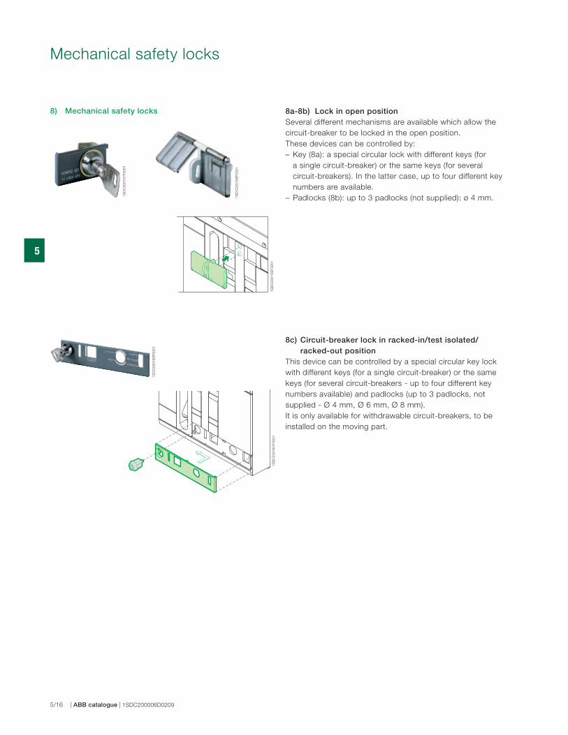
Mechanical safety locks
8a-8b) Lock in open positionSeveral different mechanisms are available which allow the
circuit-breaker to be locked in the open position.
These devices can be controlled by:
– Key (8a): a special circular lock with different keys (for
a single circuit-breaker) or the same keys (for several
circuit-breakers). In the latter case, up to four different key
numbers are available.
– Padlocks (8b): up to 3 padlocks (not supplied): ø 4 mm.
8c) Circuit-breaker lock in racked-in/test isolated/ racked-out positionThis device can be controlled by a special circular key lock
with different keys (for a single circuit-breaker) or the same
keys (for several circuit-breakers - up to four different key
numbers available) and padlocks (up to 3 padlocks, not
supplied - Ø 4 mm, Ø 6 mm, Ø 8 mm).
It is only available for withdrawable circuit-breakers, to be
installed on the moving part.
8) Mechanical safety locks
1S
DC
20
01
62
F0
00
1
1S
DC
20
01
63
F0
00
1
1S
DC
20
01
64
F0
00
1
1S
DC
20
01
65
F0
00
1
5
ABB catalogue | 1SDC200006D0209 | 5/17
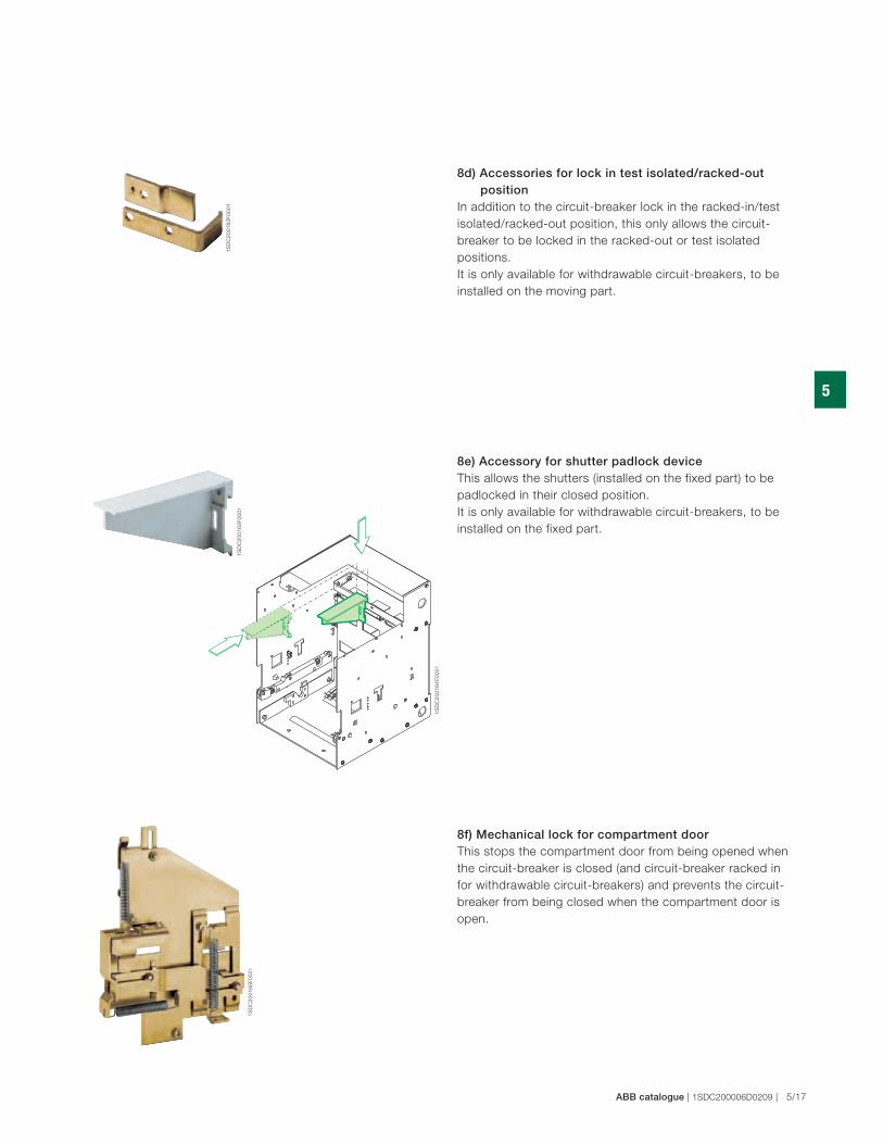
8e) Accessory for shutter padlock deviceThis allows the shutters (installed on the fixed part) to be
padlocked in their closed position.
It is only available for withdrawable circuit-breakers, to be
installed on the fixed part.
8f) Mechanical lock for compartment doorThis stops the compartment door from being opened when
the circuit-breaker is closed (and circuit-breaker racked in
for withdrawable circuit-breakers) and prevents the circuit-
breaker from being closed when the compartment door is
open.
8d) Accessories for lock in test isolated/racked-out positionIn addition to the circuit-breaker lock in the racked-in/test
isolated/racked-out position, this only allows the circuit-
breaker to be locked in the racked-out or test isolated
positions.
It is only available for withdrawable circuit-breakers, to be
installed on the moving part.
1S
DC
20
01
66
F0
00
1
1S
DC
20
01
67
F0
00
1
1S
DC
20
01
68
F0
00
1
1S
DC
20
01
69
F0
00
1
5
5/18 | ABB catalogue | 1SDC200006D0209
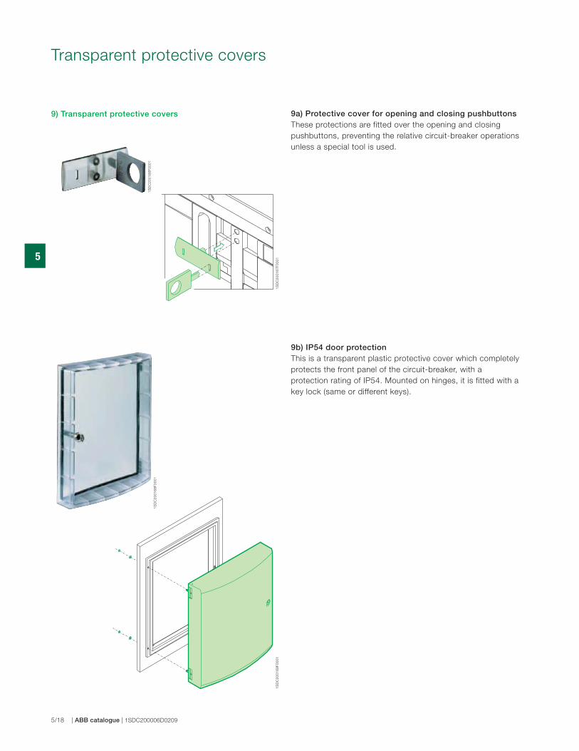
9a) Protective cover for opening and closing pushbuttonsThese protections are fitted over the opening and closing
pushbuttons, preventing the relative circuit-breaker operations
unless a special tool is used.
Transparent protective covers
9b) IP54 door protection This is a transparent plastic protective cover which completely
protects the front panel of the circuit-breaker, with a
protection rating of IP54. Mounted on hinges, it is fitted with a
key lock (same or different keys).
9) Transparent protective covers

1S
DC
20
01
70
F0
00
1
1S
DC
20
01
71
F0
00
11
SD
C2
00
17
2F
00
01
5
ABB catalogue | 1SDC200006D0209 | 5/19
Interlock between circuit-breakers
This mechanism creates a mechanical interlock between two
or three circuit-breakers (even different models and different
versions, fixed/withdrawable) using a flexible cable. The circuit
diagram for electrical switching using a relay (to be installed
by the customer) is supplied with the mechanical interlock.
The circuit-breakers can be installed vertically or horizontally.
An interlock between an Emax (E1÷E6) and a T7/X1 is
possible with dedicated cables.
Four types of mechanical interlocks are available:
Note:
See the “Overall dimensions” and “Electrical circuit diagrams” chapters for
information about dimensions (fixed and withdrawable versions) and settings.
Vertical interlock
Horizontal interlock
Type A: between 2 circuit-breakers (power supply + emergency power supply)
Type B: between 3 circuit-breakers (2 power supplies + emergency power supply)
Type C: between 3 circuit-breakers (2 power supplies + bus-tie)
Type D: between 3 circuit-breakers (3 power supplies / one single closed CB)
L interlockIt is possible to make the mechanism interlock among three
circuit-breakers disposed in “L position”.
10) Mechanical interlock
1 2
O O
I O
O I
1 2 3
O O O
I O O
O O I
I O I
O I O
1 2 3
O O O
I O O
O I O
O O I
O I I
I I O
I O I
1 2 3
O O O
I O O
O I O
O O I
�
� �
�
� � �
� � �
�
� � �
5
5/20 | ABB catalogue | 1SDC200006D0209
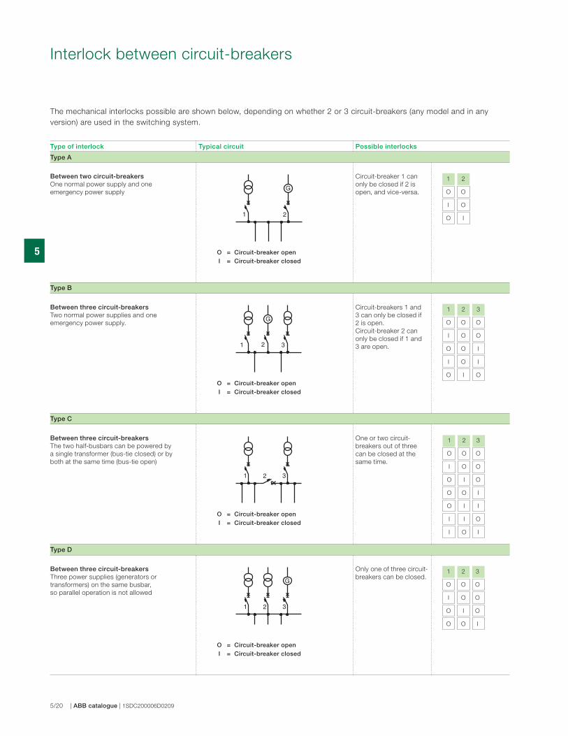
Interlock between circuit-breakers
The mechanical interlocks possible are shown below, depending on whether 2 or 3 circuit-breakers (any model and in any
version) are used in the switching system.
Type of interlock Typical circuit Possible interlocks
Type A
Between two circuit-breakersOne normal power supply and one
emergency power supply
Circuit-breaker 1 can
only be closed if 2 is
open, and vice-versa.
Type B
Between three circuit-breakersTwo normal power supplies and one
emergency power supply.
Circuit-breakers 1 and
3 can only be closed if
2 is open.
Circuit-breaker 2 can
only be closed if 1 and
3 are open.
Type C
Between three circuit-breakersThe two half-busbars can be powered by
a single transformer (bus-tie closed) or by
both at the same time (bus-tie open)
One or two circuit-
breakers out of three
can be closed at the
same time.
Type D
Between three circuit-breakersThree power supplies (generators or
transformers) on the same busbar,
so parallel operation is not allowed
Only one of three circuit-
breakers can be closed.
O = Circuit-breaker open I = Circuit-breaker closed
O = Circuit-breaker open I = Circuit-breaker closed
O = Circuit-breaker open I = Circuit-breaker closed
O = Circuit-breaker open I = Circuit-breaker closed
5
ABB catalogue | 1SDC200006D0209 | 5/21
The emergency power supply is usually provided to take over
from the normal power supply in two instances:
– to power health and safety services (e.g. hospital
installations);
– to power parts of installations which are essential for
requirements other than safety (e.g. continuous cycle
industrial plants).
The range of accessories for SACE Emax circuit-breakers
includes solutions for a wide variety of different plant
engineering requirements.
See the specific regulations regarding protections against
overcurrents, direct and indirect contacts, and provisions
to improve the reliability and safety of emergency circuits.
Switching from the normal to the emergency power supply
can either be carried out manually (locally or by remote
control) or automatically.
To this end, the circuit-breakers used for switching must be
fitted with the accessories required to allow electric remote
control and provide the electrical and mechanical interlocks
required by the switching logic.
These include:
– the shunt opening release
– the shunt closing release
– the motor operator
– the auxiliary contacts.
Switching can be automated by means of a special
electronically-controlled relay circuit, installed by the customer
(diagrams provided by ABB SACE).
Mechanical interlocks between two or three circuit-breakers
are made by using cables which can be used both for circuit-
breakers side by side or superimposed.
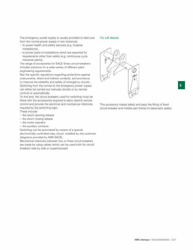
This accessory makes safety and easy the lifting of fixed
circuit-breaker and mobile part thanks to telescopic plates.
11) Lift device
5
5/22 | ABB catalogue | 1SDC200006D0209
Automatic transfer switch ATS021 and ATS022
12) Automatic transfer switch - ATS021 and ATS022
The ATS (Automatic Transfer Switch) is the Net/Net or Net/
Gen transfer unit used in installations where switching the
main power line to an emergency one is required, to ensure
power supply to the loads in the case of anomalies in the
main line.
The unit is able to manage the entire transfer procedure
automatically, and prepares the commands for carrying out
the procedure manually as well.
In the case of an anomaly in the main line voltage, in
accordance with the parameters set by the user, the
opening of the circuit-breaker of the main line, the starting
of the generator set (when provided) and the closing of the
emergency line are performed. In the same way, in the case
of the main line returning, the procedure of reverse transfer is
controlled automatically.
The new generation of ATS (ATS021 and ATS022) offers the
most advanced and complete solutions to guarantee service
continuity. The ATS021 and ATS022 can be used both with all
the circuit-breakers in the SACE Tmax XT and Emax families
and with the switch-disconnectors.
The ATS021 and ATS022 devices have been designed to
operate with self-supply. The ATS022
unit also prepares the connection for auxiliary power supply,
which allows additional functions to be used.
The ATS021 and ATS022 devices carry out control of both the
power supply lines and analyse:
• phase unbalance;
• frequency unbalance;
• phase loss.
Apart from the standard control functions, with the ATS022
unit, the following is possible:
• selecting the priority line;
• controlling a third circuit-breaker;
• incorporating the device in a supervision system with
Modbus communication (auxiliary power supply is needed);
• reading and setting the parameters, and displaying the
measurements and alarms, by means of a graphic display.
Typical applications for use are: power supply to UPS
(Uninterrupted Power Supply) units, operating rooms and
primary hospital services, emergency power supply for civil
buildings, airports, hotels, data banks and telecommunication
systems, power supply of industrial lines for continuous
processes.
For correct configuration, each circuit-breaker connected
to the ATS021 or ATS022 must be fitted with the following
accessories:
• mechanical interlock;
• motorised control of opening and closing;
• key lock against just manual operation for the motor
operator;
• contact for signalling the state (open/closed) and contact
for tripped;
• contact for racked-in (in the case of a withdrawable version
circuit-breaker).
5
ABB catalogue | 1SDC200006D0209 | 5/23
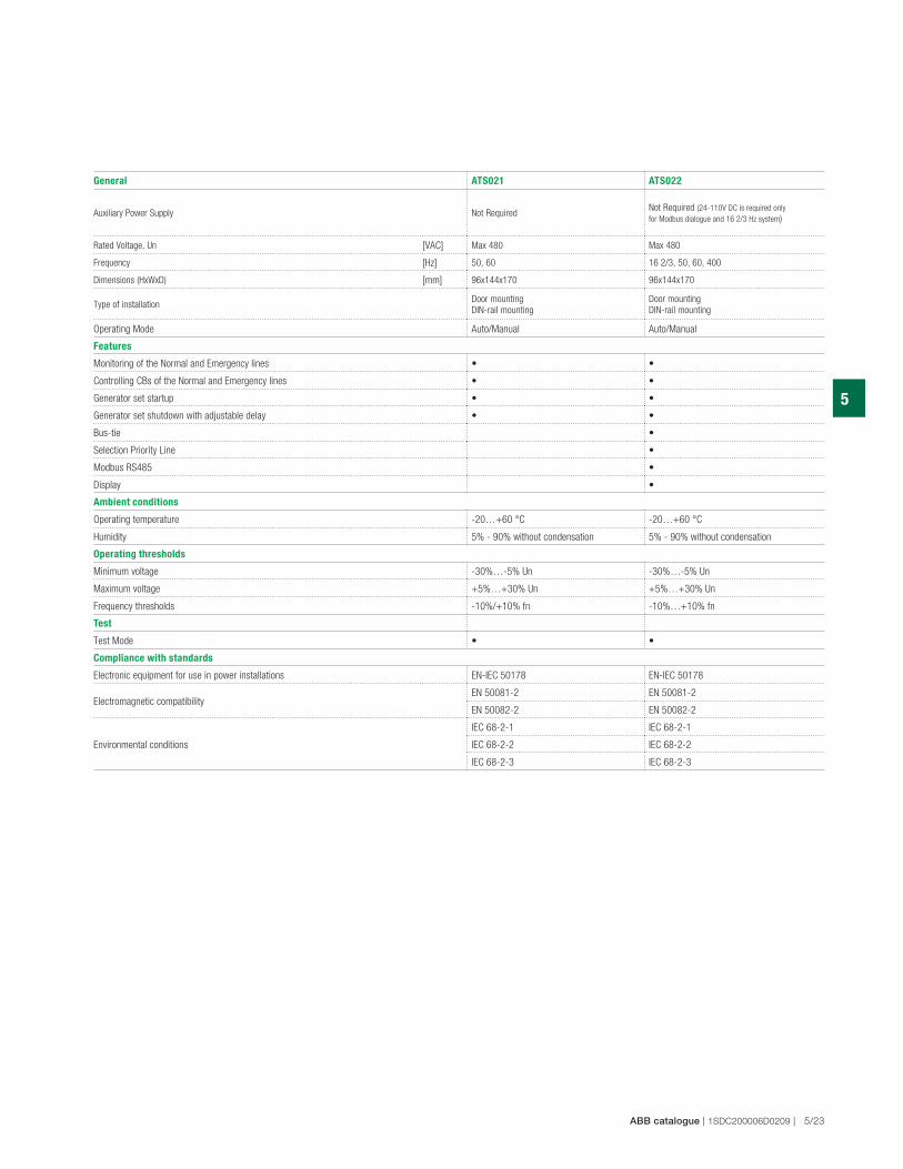
General ATS021 ATS022
Auxiliary Power Supply Not RequiredNot Required (24-110V DC is required only
for Modbus dialogue and 16 2/3 Hz system)
Rated Voltage, Un [VAC] Max 480 Max 480
Frequency [Hz] 50, 60 16 2/3, 50, 60, 400
Dimensions (HxWxD) [mm] 96x144x170 96x144x170
Type of installationDoor mounting
DIN-rail mounting
Door mounting
DIN-rail mounting
Operating Mode Auto/Manual Auto/Manual
Features
Monitoring of the Normal and Emergency lines • •
Controlling CBs of the Normal and Emergency lines • •
Generator set startup • •
Generator set shutdown with adjustable delay • •
Bus-tie •
Selection Priority Line •
Modbus RS485 •
Display •
Ambient conditions
Operating temperature -20…+60 °C -20…+60 °C
Humidity 5% - 90% without condensation 5% - 90% without condensation
Operating thresholds
Minimum voltage -30%…-5% Un -30%…-5% Un
Maximum voltage +5%…+30% Un +5%…+30% Un
Frequency thresholds -10%/+10% fn -10%…+10% fn
Test
Test Mode • •
Compliance with standards
Electronic equipment for use in power installations EN-IEC 50178 EN-IEC 50178
Electromagnetic compatibilityEN 50081-2 EN 50081-2
EN 50082-2 EN 50082-2
Environmental conditions
IEC 68-2-1 IEC 68-2-1
IEC 68-2-2 IEC 68-2-2
IEC 68-2-3 IEC 68-2-3
5
5/24 | ABB catalogue | 1SDC200006D0209
Spare partsThe following spare parts are available:
– front metal shields and escutcheon plate
– opening solenoid for PR121, PR122 and PR123 overcurrent
release
– arcing chamber
– closing springs
– jaw-type isolating contact for the fixed part of the
withdrawable circuit-breaker
– earthing sliding contact (for withdrawable version)
– shutters for fixed part
– complete pole
– operating mechanism
– connection cables for trip units and current sensors
– transparent protective cover for trip units
– SACE PR030/B power supply unit
– toolbox
– battery for SACE PR030/B power supply unit
– front escutcheon plate for Ronis key lock
For further details, please request a copy of the ABB SACE
spare parts catalogue.
Retrofitting KitsSpecial kits have been prepared to replace old SACE Otomax,
SACE Novomax G30 circuit-breakers and SACE Megamax.
The kits include SACE Emax circuit-breakers that take
advantage of all the components of the existing switchgear.
Installing a new circuit-breaker in old switchgear, offers
definite technical and economic benefits, and is extremely
rapid as there is no need to redo the main switchgear
connections.
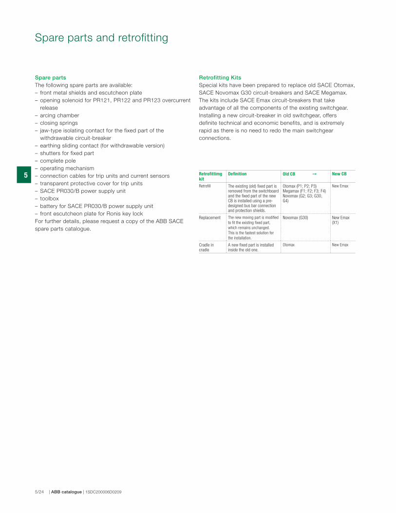
Spare parts and retrofitting
Retrofittimg
kit
Definition Old CB ➞ New CB
Retrofill The existing (old) fixed part is removed from the switchboard and the fixed part of the new CB is installed using a pre-designed bus bar connection and protection shields.
Otomax (P1; P2; P3) Megamax (F1; F2; F3; F4)Novomax (G2; G3; G30, G4)
New Emax
Replacement The new moving part is modified
to fit the existing fixed part,
which remains unchanged.
This is the fastest solution for
the installation.
Novomax (G30) New Emax (X1)
Cradle in cradle
A new fixed part is installed inside the old one.
Otomax New Emax


