Embed Size (px)
Citation preview

1
Abstract— Soft wearable robots are good alternatives to rigid-frame exoskeletons because they are compact and lightweight. This article describes a soft wearable hand robot called the Exo-Glove that uses a soft tendon routing system and an underactuation adaptive mechanism. The proposed system can be used to develop other types of soft wearable robots. The glove part of the system is compact and weighs 194 g. Results conducted using a healthy subject showed sufficient performance for the execution of daily life activities, namely, a pinch force of 20 N, a wrap grasp force of 40 N, and a maximum grasped object size of 76 mm. Use of an underactuation mechanism enabled the grasping of objects of various shapes without active control. A subject suffering from paralysis of the hands due to spinal cord injury was able to use the glove to grasp objects of various shapes. Index Terms—Exotendon, Exosuit, Hand assistive device, Hand exoskeleton, Soft exoskeleton, Soft wearable robot
A Wearable Robot Without an Exoskeleton
When people suffer paralysis of the hand and fingers in the wake of injuries or diseases such as spinal cord injury [1], stroke [2], and cerebral palsy [3], they often cannot perform even the simplest activities of daily life. Tetraplegics [1] are particularly disabled. A wearable hand robot that restores basic hand and finger function would greatly improve quality of life for people with hand motility problems. Such a hand robot should be natural looking and simple to implement, so that people feel psychologically comfortable wearing it.
A number of wearable hand robots have been developed. Most of them consist of serially connected rigid links and joints that assist body motion by applying force to the body part to which they are attached [4–8]. The positioning of these links and joints differs with the body part to which the robot is attached. The frames of hard exoskeleton robots for the legs or arms can be positioned along the sides of the limbs, but the closeness of the fingers means that the frames for a hand robot must be placed along the finger tops. To match the axes of the finger and the exoskeleton, many wearable hand robots use linkages [4-7] and rack-and-pinion mechanisms [8].
One way to overcome the limitations of a rigid wearable hand robot is to dispense with frames and instead directly attach actuators to the fingers. In this design, the function of the rigid frame of a conventional robot is performed by the finger bones, and actuation can be accomplished by mechanical tendons, air, or other soft actuators. In the literature, this concept is referred to as soft wearable robot, soft exoskeleton, exosuit [9], or exotendon [10]. Such robots naturally do not have joint alignment problems, and they are compact and lightweight because of their simple structure and the materials used to
Exo-Glove: A Soft Wearable Robot for the Hand with a Soft Tendon Routing System
By Hyunki In, Brian Byunghyun Kang, Minki Sin, and Kyu-Jin Cho
Figure 1. The Exo‐Glove allows the disabled to perform everyday tasks, greatly improving their quality of life.
Figure 2. The Exo‐Glove is easy to wear because the actuator can be positioned remotely (for example, on the upper arm or on the wheelchair).

2
make them. Several soft wearable robots for the hand have been developed [10–12], the majority of which use tendon drives [10, 12].
The tendon drive system does, however, pose some design challenges:
Tendons that are attached to the body without the use of an exoskeleton apply shear forces to the attachment points. If the tendons are attached by means of a soft material, the shear forces can move the attachment point and obstruct force transmission.
In conventional tendon drive systems, pre-tension is necessary for good performance of the robot. However, in soft wearable robots, pre-tension can cause discomfort or injury, as well as hampering efficiency because of increased friction along the tendon path.
Conventional adaptation mechanisms that enable objects to of differing shapes to be grasped by simple control use multiple rigid mechanical components. Soft wearable robots for the hand require a new adaptation mechanism to accomplish the same task.
In this article, we describe the Exo-Glove [13], a soft wearable robot for the hand that uses a soft tendon routing system inspired by the human musculoskeletal system (see figure 1, 2). The developed force transmission components are firmly attached to the body even though they consist of fabrics, with the exception of a thin anchor. All the elements of the routing system, including the actuator, are designed for operation without pre-tension, resulting in improved safety, comfort in use, and system efficiency. We developed a new adaptation mechanism for the soft tendon routing system by modifying the conventional differential mechanism. This reduced the complexity of the system and enhanced the handling of various objects. We verified the robot function experimentally with both a healthy and a disabled subject. The results demonstrated that the Exo-Glove restored grasping function to the disabled subject.
A Bio‐Inspired Soft Tendon Routing System
The Exo-Glove transmits the tension of the tendon to the body in a manner inspired by the human hand, for which tendons transmit muscular forces to induce flexion and extension of the fingers.
Three components are required for human tendons to function properly: an insertion, the origin of the muscles, and a pulley (see Figure 3). Muscles are connected to tendons, and tendons are connected to their insertion points and to the origin point of the muscles. The pulley is the annular ligament that determines the path of the tendons.
Based on the structure of the human hand, the Exo-Glove has two tendons for each finger and the thumb, several types of straps that together form the pulley, and supporting structures that form the origin of the muscles. These components are designed to transmit normal forces to the body. To generate an appropriate finger trajectory for different users, the tendon path of the routing system can be adjusted by changing the length
and position of the fabric straps.
Design Details of the Exo‐Glove
Muscle Insertion Point: A Fingertip Thimble
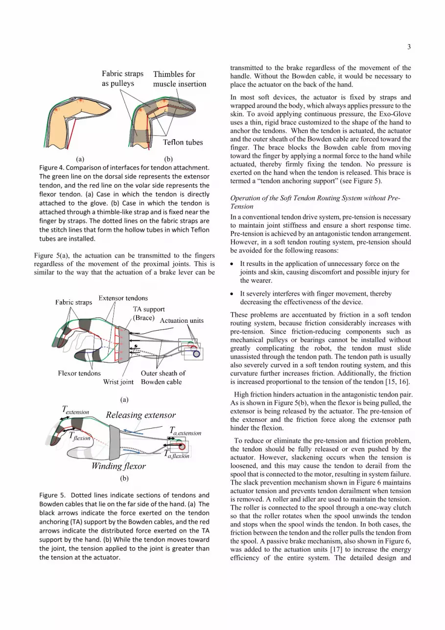
In soft wearable hand robots, special interfaces attach the tendons to the digits. The Exo-Glove uses a glove interface. One of the problems of using a glove interface is that it stretches. As can be seen from Figure 4(a), the part of the glove near the attachment point is stretched in the proximal direction when the flexor tendon is pulled.
To solve this problem, the tendons are attached to the finger by a thimble-like strap made from inextensible fabric, as shown in Figure 4(b). When the flexor tendon is pulled, the strap pushes the back and tip of the phalange, minimizing deformation of the attachment points.
Pulleys: Inextensible Fabric Straps and Teflon Tubes
In the hand, the annular ligaments attached to the bone act as pulleys, and they determine the path of the tendons as shown in Figure 3. Without the pulleys, the tendons would separate from the finger, a phenomenon referred to as bowstringing [14].
The Exo-Glove pulleys are made from fabric straps and a Teflon tube and are indicated in gray in Figure 4(b). The straps are attached to the dorsal side, with their two ends located on the left and right sides of the phalanges. Both ends of the straps are rolled up and stitched to hold the Teflon tubes, which minimizes friction when the flexor tendons move. The straps are made inextensible to maintain the moment arms of the tendons. The positions of the straps determine the moment arms and are crucial for generating the required force and posture.
Origin of Muscles: Tendon Anchoring Support
To control the fingers while also isolating them from movements of the wrist and elbow joints, the Exo-Glove uses a Bowden cable such as that used in the transmission of a bicycle brake. One end of the outer sheath of the cable is fixed to the actuator side, and the other end is fixed between the metacarpophalangeal (MCP) joint and the wrist joint. The inner tendon is then connected to the finger. As shown in
Figure 3. The human finger works via tendons, muscles, and pulleys acting on the skeleton. The muscles that connect the finger are located in the forearm and hand.
3
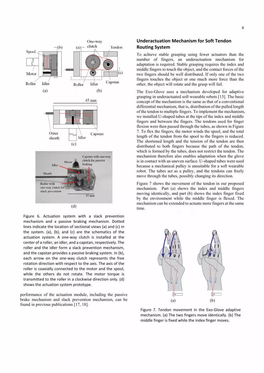
Figure 5(a), the actuation can be transmitted to the fingers regardless of the movement of the proximal joints. This is similar to the way that the actuation of a brake lever can be
transmitted to the brake regardless of the movement of the handle. Without the Bowden cable, it would be necessary to place the actuator on the back of the hand.
In most soft devices, the actuator is fixed by straps and wrapped around the body, which always applies pressure to the skin. To avoid applying continuous pressure, the Exo-Glove uses a thin, rigid brace customized to the shape of the hand to anchor the tendons. When the tendon is actuated, the actuator and the outer sheath of the Bowden cable are forced toward the finger. The brace blocks the Bowden cable from moving toward the finger by applying a normal force to the hand while actuated, thereby firmly fixing the tendon. No pressure is exerted on the hand when the tendon is released. This brace is termed a “tendon anchoring support” (see Figure 5).
Operation of the Soft Tendon Routing System without Pre-Tension
In a conventional tendon drive system, pre-tension is necessary to maintain joint stiffness and ensure a short response time. Pre-tension is achieved by an antagonistic tendon arrangement. However, in a soft tendon routing system, pre-tension should be avoided for the following reasons:
It results in the application of unnecessary force on the joints and skin, causing discomfort and possible injury for the wearer.
It severely interferes with finger movement, thereby decreasing the effectiveness of the device.
These problems are accentuated by friction in a soft tendon routing system, because friction considerably increases with pre-tension. Since friction-reducing components such as mechanical pulleys or bearings cannot be installed without greatly complicating the robot, the tendon must slide unassisted through the tendon path. The tendon path is usually also severely curved in a soft tendon routing system, and this curvature further increases friction. Additionally, the friction is increased proportional to the tension of the tendon [15, 16].
High friction hinders actuation in the antagonistic tendon pair. As is shown in Figure 5(b), when the flexor is being pulled, the extensor is being released by the actuator. The pre-tension of the extensor and the friction force along the extensor path hinder the flexion.
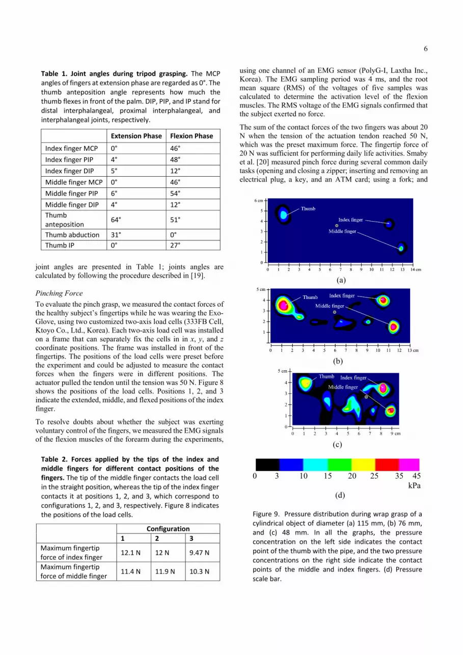
To reduce or eliminate the pre-tension and friction problem, the tendon should be fully released or even pushed by the actuator. However, slackening occurs when the tension is loosened, and this may cause the tendon to derail from the spool that is connected to the motor, resulting in system failure. The slack prevention mechanism shown in Figure 6 maintains actuator tension and prevents tendon derailment when tension is removed. A roller and idler are used to maintain the tension. The roller is connected to the spool through a one-way clutch so that the roller rotates when the spool unwinds the tendon and stops when the spool winds the tendon. In both cases, the friction between the tendon and the roller pulls the tendon from the spool. A passive brake mechanism, also shown in Figure 6, was added to the actuation units [17] to increase the energy efficiency of the entire system. The detailed design and
(a)
(b)
Figure 5. Dotted lines indicate sections of tendons and Bowden cables that lie on the far side of the hand. (a) The black arrows indicate the force exerted on the tendon anchoring (TA) support by the Bowden cables, and the red arrows indicate the distributed force exerted on the TA support by the hand. (b) While the tendon moves toward the joint, the tension applied to the joint is greater than the tension at the actuator.
(a) (b)
Figure 4. Comparison of interfaces for tendon attachment. The green line on the dorsal side represents the extensor tendon, and the red line on the volar side represents the flexor tendon. (a) Case in which the tendon is directly attached to the glove. (b) Case in which the tendon is attached through a thimble‐like strap and is fixed near the finger by straps. The dotted lines on the fabric straps are the stitch lines that form the hollow tubes in which Teflon tubes are installed.
4
performance of the actuation module, including the passive brake mechanism and slack prevention mechanism, can be found in previous publications [17, 18].
Underactuation Mechanism for Soft Tendon Routing System
To achieve stable grasping using fewer actuators than the number of fingers, an underactuation mechanism for adaptation is required. Stable grasping requires the index and middle fingers to touch the object, and the contact forces of the two fingers should be well distributed. If only one of the two fingers touches the object or one much more force than the other, the object will rotate and the grasp will fail.
The Exo-Glove uses a mechanism developed for adaptive grasping in underactuated soft wearable robots [13]. The basic concept of the mechanism is the same as that of a conventional differential mechanism, that is, distribution of the pulled length of the tendon to multiple fingers. To implement the mechanism, we installed U-shaped tubes at the tips of the index and middle fingers and between the fingers. The tendons used for finger flexion were then passed through the tubes, as shown in Figure 7. To flex the fingers, the motor winds the spool, and the total length of the tendon from the spool to the fingers is reduced. The shortened length and the tension of the tendon are then distributed to both fingers because the path of the tendon, which is formed by the tubes, does not restrict the tendon. The mechanism therefore also enables adaptation when the glove is in contact with an uneven surface. U-shaped tubes were used because a mechanical pulley is unsuitable for a soft wearable robot. The tubes act as a pulley, and the tendons can freely move through the tubes, possibly changing its direction.
Figure 7 shows the movement of the tendon in our proposed mechanism. Part (a) shows the index and middle fingers moving identically, and part (b) shows the index finger fixed by the environment while the middle finger is flexed. The mechanism can be extended to actuate more fingers at the same time.
(a) (b)
Figure 7. Tendon movement in the Exo‐Glove adaptive mechanism. (a) The two fingers move identically. (b) The middle finger is fixed while the index finger moves.
(a) (b)
(c)
(d)
Figure 6. Actuation system with a slack prevention mechanism and a passive braking mechanism. Dotted lines indicate the location of sectional views (a) and (c) in the system. (a), (b), and (c) are the schematics of the actuation system. A one‐way clutch is installed at the center of a roller, an idler, and a capstan, respectively. The roller and the idler form a slack prevention mechanism, and the capstan provides a passive braking system. In (b), each arrow on the one‐way clutch represents the free rotation direction with respect to the axis. The axis of the roller is coaxially connected to the motor and the spool, while the others do not rotate. The motor torque is transmitted to the roller in a clockwise direction only. (d) shows the actuation system prototype.

5
Control and Command
Considering that the expected users of the Exo-Glove are people with some type of disability, the input command for the control has been made as simple as possible. Specifically, admittance control is used. . This control makes the tendon act as a virtual compliant spring, with the single input command being used to determine the pulled length of the virtual spring. Moreover, the compliance characteristic of the admittance control guarantees the safety of the device.
As regards the control input, various types of human–robot interfaces such as electromyography (EMG), electroencephalography (EEG), and analog switches for detecting body motion could be used. Here, wrist motion has been considered for the following two reasons. First, wrist motion is easy to detect and is reliable. For example, a simple bend sensor can detect wrist motion with high reliability. Second, people with a paralyzed hand are generally familiar with performing wrist motion to induce finger motion to grasp an object. Wrist motion is connected to finger motion by a mechanism referred to as the tenodesis effect, which is the flexing of the finger when the wrist is extended. It should be noted that the use of wrist motion as control input eliminates one degree of freedom from the movement of the hand, thereby restricting the position in which the object can be grabbed. This issue can, however, be solved by adding another combinable control input. Nevertheless, the simplicity of wrist motion makes it a good candidate for the control input for assisting the disabled. Here, a resistor bend sensor installed at the back of the wrist is used to measure the angle of the wrist.
Performance of the Exo‐Glove
We experimentally investigated the grasp performance of the Exo-Glove by testing the device with two male subjects, one a healthy 30-year-old and the other a disabled 41-year-old who six months earlier had sustained traumatic injury to the fourth cervical spine (C4; ASIA B), resulting in tetraplegia. The disabled subject could neither flex nor extend his fingers but could move his elbow and shoulder. After measuring the Exo-Glove kinematics, pinching force, and wrap grasping force with the healthy subject, we observed both subjects as they attempted to grasp variously shaped objects while wearing the device. All procedures were approved by the Institutional Review Board of Seoul National University (IRB No. 1401/001-019).
Kinematics
To demonstrate the kinematic characteristics of the Exo-Glove, we used an infrared vision system to film finger motions of the healthy subject while he was wearing the device. Thirteen retro-reflective hemispheric markers, each 4 mm in diameter, were attached to the fingertips, the joints of the index and middle fingers and the thumb, and the ulnar and upside of the wrist. Eight infrared video cameras (Bonita B3, Vicon Inc.) were positioned around the hand, and the working volume (50 × 50 × 50 cm3) was calibrated to produce an accuracy of less than 0.3 mm. The capture rate was 100 frames/s, and the resolution of each frame was 300,000 pixels.
The finger trajectory was captured while the finger was flexed from the extended posture. The extended posture was achieved by pulling the extensor until the fingers were straight. The fingers and thumb were then flexed until their tips met. This was done by simultaneously releasing the extensor and pulling the flexor.
The positions of the markers shown in Figure 8 correspond to the extended posture. The line beginning from each marker represents the trajectory of the marker while the digits were flexed.
As shown in Figure 8, sufficient extension and flexion ranges could be achieved, and the tips of the fingers and thumb met at a point when flexed. Although the flexion range was smaller than that of voluntary movement of the fingers, it was sufficient for pinching and wrap grasping. The ranges of the
(a)
(b) Figure 8. Achievable flexion/extension ranges of the index and middle fingers when using the Exo‐Glove without contacting an object. The circular, rectangular, and triangular markers in the figure represent the markers attached to the thumb, index finger, and middle finger, respectively. (a) shows the trajectory of the digits in the sagittal plane, and (b) shows the trajectory in the frontal plane. The three positions marked by the stars in (a) indicate the positions of the load cells used to measure the pinching force.
6
joint angles are presented in Table 1; joints angles are calculated by following the procedure described in [19].
Pinching Force
To evaluate the pinch grasp, we measured the contact forces of the healthy subject’s fingertips while he was wearing the Exo-Glove, using two customized two-axis load cells (333FB Cell, Ktoyo Co., Ltd., Korea). Each two-axis load cell was installed on a frame that can separately fix the cells in in x, y, and z coordinate positions. The frame was installed in front of the fingertips. The positions of the load cells were preset before the experiment and could be adjusted to measure the contact forces when the fingers were in different positions. The actuator pulled the tendon until the tension was 50 N. Figure 8 shows the positions of the load cells. Positions 1, 2, and 3 indicate the extended, middle, and flexed positions of the index finger.
To resolve doubts about whether the subject was exerting voluntary control of the fingers, we measured the EMG signals of the flexion muscles of the forearm during the experiments,
using one channel of an EMG sensor (PolyG-I, Laxtha Inc., Korea). The EMG sampling period was 4 ms, and the root mean square (RMS) of the voltages of five samples was calculated to determine the activation level of the flexion muscles. The RMS voltage of the EMG signals confirmed that the subject exerted no force.
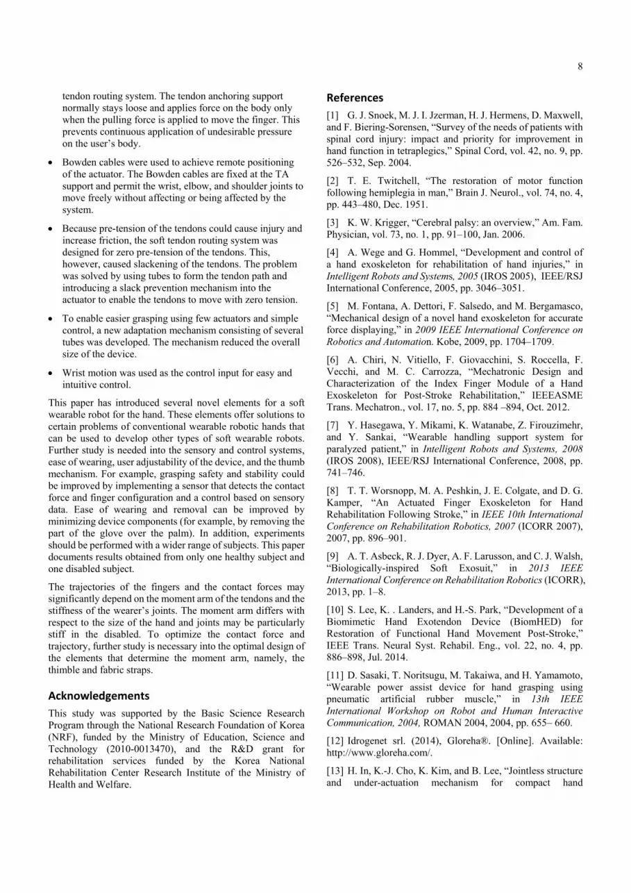
The sum of the contact forces of the two fingers was about 20 N when the tension of the actuation tendon reached 50 N, which was the preset maximum force. The fingertip force of 20 N was sufficient for performing daily life activities. Smaby et al. [20] measured pinch force during several common daily tasks (opening and closing a zipper; inserting and removing an electrical plug, a key, and an ATM card; using a fork; and
Table 1. Joint angles during tripod grasping. The MCP angles of fingers at extension phase are regarded as 0°. The thumb anteposition angle represents how much the thumb flexes in front of the palm. DIP, PIP, and IP stand for distal interphalangeal, proximal interphalangeal, and interphalangeal joints, respectively.
Extension Phase Flexion Phase
Index finger MCP 0° 46°
Index finger PIP 4° 48°
Index finger DIP 5° 12°
Middle finger MCP 0° 46°
Middle finger PIP 6° 54°
Middle finger DIP 4° 12°
Thumb anteposition
64° 51°
Thumb abduction 31° 0°
Thumb IP 0° 27°
Table 2. Forces applied by the tips of the index and middle fingers for different contact positions of the fingers. The tip of the middle finger contacts the load cell in the straight position, whereas the tip of the index finger contacts it at positions 1, 2, and 3, which correspond to configurations 1, 2, and 3, respectively. Figure 8 indicates the positions of the load cells.
Configuration
1 2 3
Maximum fingertip force of index finger
12.1 N 12 N 9.47 N
Maximum fingertip force of middle finger
11.4 N 11.9 N 10.3 N
(a)
(b)
(c)
0 3 10 15 20 25 35 45 kPa
(d)
Figure 9. Pressure distribution during wrap grasp of a cylindrical object of diameter (a) 115 mm, (b) 76 mm, and (c) 48 mm. In all the graphs, the pressure concentration on the left side indicates the contact point of the thumb with the pipe, and the two pressure concentrations on the right side indicate the contact points of the middle and index fingers. (d) Pressure scale bar.

7
pressing a remote control button) and found that most of them required less than 20 N.
Table 2 shows the fingertip forces at which the middle finger and index finger respectively touched the load cell. As expected, the difference between the fingertip forces increased with increasing distance between the tips of the index and middle fingers. The maximum difference between the fingertip forces was less than 1 N and occurred when the tips were farthest from each other. The value is quite small considering that the force required to press a remote control button is about 1 N [20].
Wrap Grasping Force
A wrap grasp with the palm and fingers is used to grasp comparably large and heavy objects. We measured wrap grasping force by having the healthy subject using the Exo-Glove grasp three pipes of different diameters, each wrapped with a mat sensor that measured pressure distribution during the grasp (160 x 160 mm2 sensor; Pliance® Hand Mat Sensor, Novel Inc., Germany). The pipes were installed on a table in the vertical position, and the subject naturally moved his hand to them. The device motor pulled the flexion tendon until the tension of the tendon was 50 N.
During the experiment, the RMS voltage of the EMG signals confirmed that the subject exerted no force. The subject was able to grasp the two smallest pipes, but the pipe of diameter 115 mm was too large and slipped out of his hand. The graphs in Figure 9 show the pressure distributions when the tension of the actuation tendon was 50 N, with the exception of the grasp failure. Figure 9(a) shows the maximum force achieved before the subject lost hold of the largest pipe. The maximum sum of all the normal forces during pipe grasping was about 40 N. The fact that all the forces were normal indicates that a cylindrical object with a mass of about 2 kg can be held, assuming that the friction coefficient between the glove and the object is 0.5. The force is thus sufficient for performing daily tasks such as grasping cups and bottles.
Grasping of Objects of Various Shapes
In the final experiments, both the healthy subject and the disabled subject grasped the following target objects: a plastic bottle containing 400 ml of water, a baseball, a 500 g calibration weight, and a spray container half-filled with water. During the experiments, the subjects could choose the approach path and orientation of their hand. Even though the subject used the Exo-Glove at the experiment for the first time, thanks to the simple control method and adaptation mechanism, the subject successfully used the Exo-Glove. Figure 10 shows the grasp performance of the disabled subject while using the Exo-Glove. After the experiment, the subject was very satisfied to grasp various objects by himself.
Conclusion
The Exo-Glove is most suitable for people incapable of closing or opening their hands but able to use other joints of the upper limb, including wrist, elbow, and shoulder joints. The Exo-Glove can also be used by people with medium- to low-level finger spasticity, as long as all finger joints exhibit the same degree of spasticity. When the spasticity varies widely among the finger joints, it is difficult to achieve effective movements with the Exo-Glove, even if the design is adjusted for the user. High spasticity precludes using the Exo-Glove because the high tendon tension that would be required could harm the user’s skin.
Because the conventional elements of a hard exoskeleton are unsuitable for the soft structure of the proposed device, the Exo-Glove employs a new design inspired by human finger anatomy. Owing to the inherent features of the soft structure, no joint alignment was required between the device and the human body, which enhances the simplicity of the device. The following new elements were developed for Exo-Glove:
The mechanical pulleys used in conventional tendon routing systems were replaced by fabric straps and Teflon tubes.
A thimble and tendon anchoring support were used to achieve a fixed point of force transmission in the soft
Figure 10. Various grasping motions achieved by a tetraplegic subject using the Exo‐Glove. The simple human–robot interface and underactuation mechanisms made it easy for the subject to grasp the objects.
8
tendon routing system. The tendon anchoring support normally stays loose and applies force on the body only when the pulling force is applied to move the finger. This prevents continuous application of undesirable pressure on the user’s body.
Bowden cables were used to achieve remote positioning of the actuator. The Bowden cables are fixed at the TA support and permit the wrist, elbow, and shoulder joints to move freely without affecting or being affected by the system.
Because pre-tension of the tendons could cause injury and increase friction, the soft tendon routing system was designed for zero pre-tension of the tendons. This, however, caused slackening of the tendons. The problem was solved by using tubes to form the tendon path and introducing a slack prevention mechanism into the actuator to enable the tendons to move with zero tension.
To enable easier grasping using few actuators and simple control, a new adaptation mechanism consisting of several tubes was developed. The mechanism reduced the overall size of the device.
Wrist motion was used as the control input for easy and intuitive control.
This paper has introduced several novel elements for a soft wearable robot for the hand. These elements offer solutions to certain problems of conventional wearable robotic hands that can be used to develop other types of soft wearable robots. Further study is needed into the sensory and control systems, ease of wearing, user adjustability of the device, and the thumb mechanism. For example, grasping safety and stability could be improved by implementing a sensor that detects the contact force and finger configuration and a control based on sensory data. Ease of wearing and removal can be improved by minimizing device components (for example, by removing the part of the glove over the palm). In addition, experiments should be performed with a wider range of subjects. This paper documents results obtained from only one healthy subject and one disabled subject.
The trajectories of the fingers and the contact forces may significantly depend on the moment arm of the tendons and the stiffness of the wearer’s joints. The moment arm differs with respect to the size of the hand and joints may be particularly stiff in the disabled. To optimize the contact force and trajectory, further study is necessary into the optimal design of the elements that determine the moment arm, namely, the thimble and fabric straps.
Acknowledgements
This study was supported by the Basic Science Research Program through the National Research Foundation of Korea (NRF), funded by the Ministry of Education, Science and Technology (2010-0013470), and the R&D grant for rehabilitation services funded by the Korea National Rehabilitation Center Research Institute of the Ministry of Health and Welfare.
References
[1] G. J. Snoek, M. J. I. Jzerman, H. J. Hermens, D. Maxwell, and F. Biering-Sorensen, “Survey of the needs of patients with spinal cord injury: impact and priority for improvement in hand function in tetraplegics,” Spinal Cord, vol. 42, no. 9, pp. 526–532, Sep. 2004.
[2] T. E. Twitchell, “The restoration of motor function following hemiplegia in man,” Brain J. Neurol., vol. 74, no. 4, pp. 443–480, Dec. 1951.
[3] K. W. Krigger, “Cerebral palsy: an overview,” Am. Fam. Physician, vol. 73, no. 1, pp. 91–100, Jan. 2006.
[4] A. Wege and G. Hommel, “Development and control of a hand exoskeleton for rehabilitation of hand injuries,” in Intelligent Robots and Systems, 2005 (IROS 2005), IEEE/RSJ International Conference, 2005, pp. 3046–3051.
[5] M. Fontana, A. Dettori, F. Salsedo, and M. Bergamasco, “Mechanical design of a novel hand exoskeleton for accurate force displaying,” in 2009 IEEE International Conference on Robotics and Automation. Kobe, 2009, pp. 1704–1709.
[6] A. Chiri, N. Vitiello, F. Giovacchini, S. Roccella, F. Vecchi, and M. C. Carrozza, “Mechatronic Design and Characterization of the Index Finger Module of a Hand Exoskeleton for Post-Stroke Rehabilitation,” IEEEASME Trans. Mechatron., vol. 17, no. 5, pp. 884 –894, Oct. 2012.
[7] Y. Hasegawa, Y. Mikami, K. Watanabe, Z. Firouzimehr, and Y. Sankai, “Wearable handling support system for paralyzed patient,” in Intelligent Robots and Systems, 2008 (IROS 2008), IEEE/RSJ International Conference, 2008, pp. 741–746.
[8] T. T. Worsnopp, M. A. Peshkin, J. E. Colgate, and D. G. Kamper, “An Actuated Finger Exoskeleton for Hand Rehabilitation Following Stroke,” in IEEE 10th International Conference on Rehabilitation Robotics, 2007 (ICORR 2007), 2007, pp. 896–901.
[9] A. T. Asbeck, R. J. Dyer, A. F. Larusson, and C. J. Walsh, “Biologically-inspired Soft Exosuit,” in 2013 IEEE International Conference on Rehabilitation Robotics (ICORR), 2013, pp. 1–8.
[10] S. Lee, K. . Landers, and H.-S. Park, “Development of a Biomimetic Hand Exotendon Device (BiomHED) for Restoration of Functional Hand Movement Post-Stroke,” IEEE Trans. Neural Syst. Rehabil. Eng., vol. 22, no. 4, pp. 886–898, Jul. 2014.
[11] D. Sasaki, T. Noritsugu, M. Takaiwa, and H. Yamamoto, “Wearable power assist device for hand grasping using pneumatic artificial rubber muscle,” in 13th IEEE International Workshop on Robot and Human Interactive Communication, 2004, ROMAN 2004, 2004, pp. 655– 660.
[12] Idrogenet srl. (2014), Gloreha®. [Online]. Available: http://www.gloreha.com/.
[13] H. In, K.-J. Cho, K. Kim, and B. Lee, “Jointless structure and under-actuation mechanism for compact hand

9
exoskeleton,” in 2011 IEEE International Conference on Rehabilitation Robotics (ICORR), 2011, pp. 1–6.
[14] G.-T. Lin, P. C. Amadio, K.-N. An, and W. P. Cooney, “Functional anatomy of the human digital flexor pulley system,” J. Hand Surg., vol. 14, no. 6, pp. 949–956, 1989.
[15] S. Crandall and T. Lardner, An Introduction to the Mechanics of Solids: Second Edition with SI Units, 2 edition. Boston: McGraw-Hill Science/Engineering/Math, 1999.
[16] H. In, D. Lee, and K.-J. Cho, “Investigation of friction characteristics of a tendon driven wearable robotic hand,” in 2010 International Conference on Control Automation and Systems (ICCAS), 2010, pp. 568–573.
[17] S. Kang, H. In, and K.-J. Cho, “Design of a passive brake mechanism for tendon driven devices,” Int. J. Precis. Eng. Manuf., vol. 13, no. 8, pp. 1487–1490, 2012.
[18] H. In, S. Kang, and K.-J. Cho, “Capstan brake: Passive brake for tendon-driven mechanism,” in 2012 IEEE/RSJ International Conference on Intelligent Robots and Systems (IROS), 2012, pp. 2301–2306.
[19] I. Carpinella, P. Mazzoleni, M. Rabuffetti, R. Thorsen, and M. Ferrarin, “Experimental protocol for the kinematic analysis of the hand: definition and repeatability,” Gait Posture, vol. 23, no. 4, pp. 445–454, Jun. 2006.
[20] N. Smaby, M. E. Johanson, B. Baker, D. E. Kenney, W. M. Murray, and V. R. Hentz, “Identification of key pinch forces required to complete functional tasks,” J. Rehabil. Res. Dev., vol. 41, no. 2, pp. 215–224, Mar. 2004.


