Embed Size (px)
Citation preview
IEEE TRANSACTIONS ON ROBOTICS AND AUTOMATION, VOL. XX, NO. Y, MONTH 2001 1
A Framework forVision Based Formation Control
Aveek Das, Rafael Fierro, Vijay Kumar, Jim Ostrowski, John Spletzer, and Camillo Taylor
Abstract—We describe a framework for controlling and coordinating agroup of nonholonomic mobile robots for cooperative tasks ranging fromscouting and reconnaissance to distributed manipulation.The frameworkallows us to build complex systems from simple controllers and estimators.This modular approach is attractive because of the potential for reusability.In addition, we show that our approach to composition also guarantees sta-bility and convergence in a wide range of tasks. There are twokey featuresin our approach. The first is a paradigm for switching betweensimple de-centralized controllers thus allowing changes in the formation. Second, allthe controllers use information from a single sensor — an omnidirectionalcamera. We describe estimators that abstract the sensory information atdifferent levels enabling decentralized as well as cooperative control. Ourresults consist of numerical simulations as well as experiments on a plat-form of three nonholonomic robots.
Keywords—Hybrid control, formation control, cooperative localization,distributed manipulation, nonholonomic mobile robots.
I. I NTRODUCTION
The last few years have seen active research in the field ofcontrol and coordination for multiple mobile robots, and appli-cation to tasks such as exploration [1], surveillance [2], searchand rescue [3], mapping of unknown or partially known envi-ronments [4], [5], distributed manipulation [6], [7] and trans-portation of large objects [8], [9]. An excellent review of con-temporary work in this area is presented in [10].
While robot control is considered to be a well understoodproblem area [11], most of the current success stories in multi-robot coordination do not rely on or build on the results avail-able in the control theory and dynamical systems literature. Thereason for this is fairly clear. Traditional control theory mostlyenables the design of controllers in a single mode of operation,in which the task and the model of the system are fixed [12],[13], [14]. When operating in unstructured or dynamic envi-ronments with many different sources of uncertainty, it is verydifficult if not impossible to design controllers that will guaran-tee performance even in a local sense. A similar problem existsin developing estimators in the context of sensing, and mappingand motion planning.
In contrast, we know that it is relatively easy to design re-active controllers or behaviors that react to simple stimuli orcommands from the environment. We can see successful ap-plications of this idea in the subsumption architecture [15], inthe paradigm for behavior-based robotics [16], [17], [18], and inother work [10].
In this paper we address the development of intelligent robotsystems by composing simple building blocks in a bottom-upapproach. The building blocks consist of controllers and esti-mators, and the framework for composition allows for tightly-coupled perception-action loops. While this philosophy is sim-ilar in spirit to the behavior based control paradigm [15], we
GRASP Labratory, University of Pennsylvania, Philadelphia PA,faveek,rfierro,kumar,jpo,spletzer,[email protected]
differ in the control-theoretic approach to the development ofthe basic components, and our formal approach to their compo-sition.
The goal of this paper is to develop a framework for com-position of simple controllers and estimators to control the for-mation of a group of robots. By formation control, we simplymean the problem of controlling the relative positions and orien-tations of robots in a group, while allowing the group to move asa whole. We are particularly interested in problems of coopera-tive manipulation, where a “rigid” formation may be necessaryto transport a grasped object to a prescribed location, and co-operative mapping, where the formation may be defined by aminimal (in comparison) set of constraints.
Problems in formation control that have been investigated in-clude assignment of feasible formations [19], [20], [21], get-ting into formation [22], [23], [24], maintenance of formationshape [25], [26], [27] and switching between formations [28],[29]. Approaches to modeling and solving these problems havebeen diverse, ranging from paradigms based on combining re-active behaviors [17], [30] to those based on leader-followergraphs [25] and virtual structures [31], [32].
In this paper we describe a suite of controllers and estimatorsand a methodology for their composition that permits control offormations for a group of robots in all the above and other appli-cations. This suite consists of centralized as well as decentral-ized algorithms — either can be used depending on the nature ofthe communication link. We consider situations in which theremay be no access to any global positioning system and the mainsensing modality is vision. All our estimators are derived fromvision. Our platform of interest is a nonholonomic car-like robotwith a single physical sensor - an omnidirectional camera. Thewider field of view offered by this camera allows us to extractmore information from the video signal than conventional cam-eras and makes it possible to implement a wider range of motionstrategies on the same platform.
Our contributions in this paper are two-fold. First we developa bottom-up approach to building controllers and estimators, anddescribe, in some detail, the components used for multi-robotcoordination. These include simple decentralized, reactive con-trollers for obstacle avoidance, collision recovery and pursuingtargets, and more complex controllers for maintaining forma-tion, controllers that can be either centralized or decentralizedand are derived from input-output linearization. Our secondcontribution is the framework for multi-robot coordination thatallows robots to maintain or change formation while followinga specified trajectory, and to perform cooperative manipulationtasks. We require a robot to be designated as thereferencerobotor leader. All other robots choose an appropriate controller de-pending on the their relative position and converge on the de-sired formation. Our framework involves a sequential composi-
IEEE TRANSACTIONS ON ROBOTICS AND AUTOMATION, VOL. XX, NO. Y, MONTH 2001 2
tion of controllers, or modes, and we show that the dynamics ofthe resulting switched system are stable.
The rest of this paper is organized as follows. First we give abroad overview of our framework in Section II, and illustratesome of the salient features using our nonholonomic mobilerobot experimental testbed. In Section III we present a set ofcontrollers that serve as the building blocks for formation con-trol. We discuss the assignment of formations, changes in for-mations, and stable switching strategies in Section IV using agroup of three robots as an example. Section V addresses thecentralized and decentralized schemes for sensing and estima-tion for implementation of formation control. Hardware de-tails and experimental results illustrating the application of thismethodology to cooperative tasks are in Section VI. Finally,some concluding remarks and directions for future work are pro-vided in Section VII.
II. FRAMEWORK
In this section, we describe a framework for cooperative con-trol of multiple mobile robots. We are motivated by theoreticalideas and modern tools in software engineering, and the emerg-ing theory of hybrid systems1.
The software for each robot consists of components calledagents. Agents operate concurrently and lend themselves topar-allel composition. Each agent consists of a mainmode, that mayin turn havesubmodes. A mode is a discrete state characterizedby a set of differential equations and constraints. The concept ofmodes allows us to formally define the notion of sequential com-position. Definition of submodes implicitly define the notion ofhierarchical composition.
RangeMapper
CollisionDetector
TargetDetector
EdgeDetector
Color BlobExtractor
AutonomousNavigation
LeaderFollowing
CollisionRecovery
ObstacleAvoidance
Frame Grabber Motion Controller
Coordination Protocol
ObstacleDetector
Relative State Observer
Decentralized Centralized
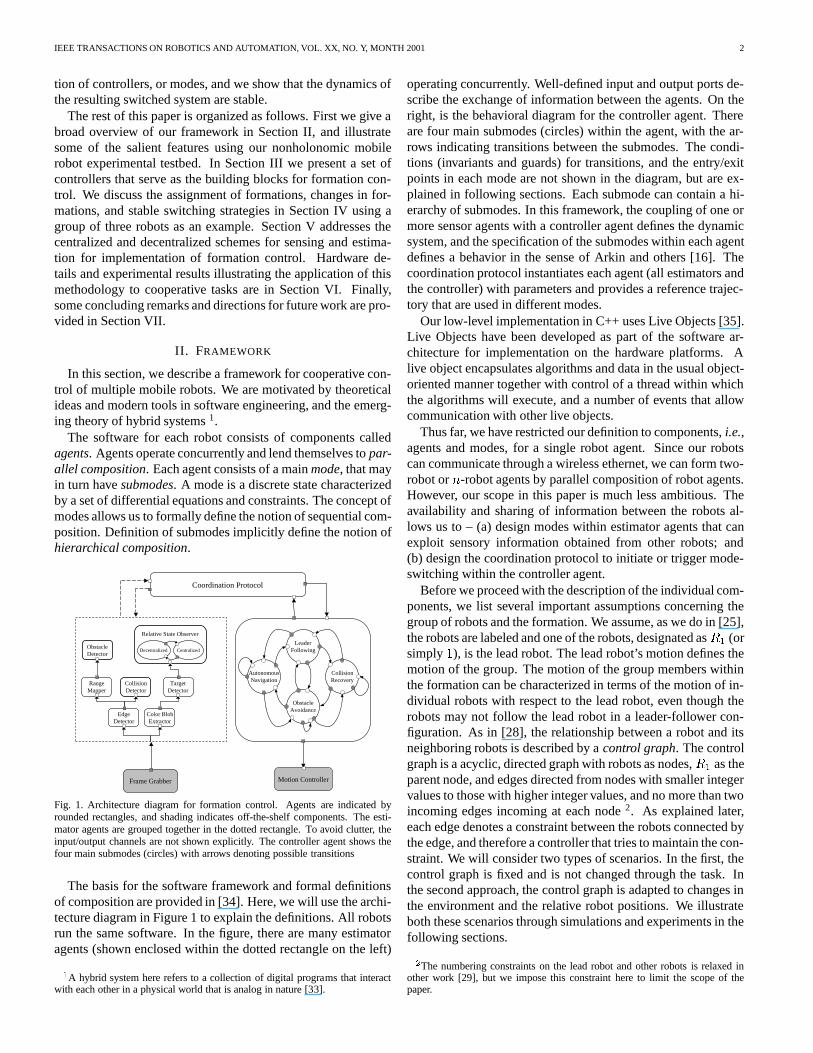
Fig. 1. Architecture diagram for formation control. Agentsare indicated byrounded rectangles, and shading indicates off-the-shelf components. The esti-mator agents are grouped together in the dotted rectangle. To avoid clutter, theinput/output channels are not shown explicitly. The controller agent shows thefour main submodes (circles) with arrows denoting possibletransitions
The basis for the software framework and formal definitionsof composition are provided in [34]. Here, we will use the archi-tecture diagram in Figure 1 to explain the definitions. All robotsrun the same software. In the figure, there are many estimatoragents (shown enclosed within the dotted rectangle on the left)1A hybrid system here refers to a collection of digital programs that interactwith each other in a physical world that is analog in nature [33].
operating concurrently. Well-defined input and output ports de-scribe the exchange of information between the agents. On theright, is the behavioral diagram for the controller agent. Thereare four main submodes (circles) within the agent, with the ar-rows indicating transitions between the submodes. The condi-tions (invariants and guards) for transitions, and the entry/exitpoints in each mode are not shown in the diagram, but are ex-plained in following sections. Each submode can contain a hi-erarchy of submodes. In this framework, the coupling of one ormore sensor agents with a controller agent defines the dynamicsystem, and the specification of the submodes within each agentdefines a behavior in the sense of Arkin and others [16]. Thecoordination protocol instantiates each agent (all estimators andthe controller) with parameters and provides a reference trajec-tory that are used in different modes.
Our low-level implementation in C++ uses Live Objects [35].Live Objects have been developed as part of the software ar-chitecture for implementation on the hardware platforms. Alive object encapsulates algorithms and data in the usual object-oriented manner together with control of a thread within whichthe algorithms will execute, and a number of events that allowcommunication with other live objects.
Thus far, we have restricted our definition to components,i.e.,agents and modes, for a single robot agent. Since our robotscan communicate through a wireless ethernet, we can form two-robot orn-robot agents by parallel composition of robot agents.However, our scope in this paper is much less ambitious. Theavailability and sharing of information between the robots al-lows us to – (a) design modes within estimator agents that canexploit sensory information obtained from other robots; and(b) design the coordination protocol to initiate or trigger mode-switching within the controller agent.
Before we proceed with the description of the individual com-ponents, we list several important assumptions concerning thegroup of robots and the formation. We assume, as we do in [25],the robots are labeled and one of the robots, designated asR1 (orsimply1), is the lead robot. The lead robot’s motion defines themotion of the group. The motion of the group members withinthe formation can be characterized in terms of the motion of in-dividual robots with respect to the lead robot, even though therobots may not follow the lead robot in a leader-follower con-figuration. As in [28], the relationship between a robot and itsneighboring robots is described by acontrol graph. The controlgraph is a acyclic, directed graph with robots as nodes,R1 as theparent node, and edges directed from nodes with smaller integervalues to those with higher integer values, and no more than twoincoming edges incoming at each node2. As explained later,each edge denotes a constraint between the robots connected bythe edge, and therefore a controller that tries to maintain the con-straint. We will consider two types of scenarios. In the first, thecontrol graph is fixed and is not changed through the task. Inthe second approach, the control graph is adapted to changes inthe environment and the relative robot positions. We illustrateboth these scenarios through simulations and experiments in thefollowing sections.2The numbering constraints on the lead robot and other robotsis relaxed inother work [29], but we impose this constraint here to limit the scope of thepaper.
IEEE TRANSACTIONS ON ROBOTICS AND AUTOMATION, VOL. XX, NO. Y, MONTH 2001 3
III. CONTROL ALGORITHMS
A. Modeling
In this section, we describe control algorithms that specifythe interactions between each robot and its neighbor(s) or theenvironment. The robots are velocity controlled nonholonomiccar-like platforms and have two independent inputs. The con-trol laws are based on input-output feedback linearization. Thismeans we are able to regulate two outputs. The kinematics oftheith robot are given by_xi = vi cos �i; _yi = vi sin �i; _�i = !i; (1)
wherexi � (xi; yi; �i) 2 SE(2), andvi and!i are the linearand angular velocities, respectively.
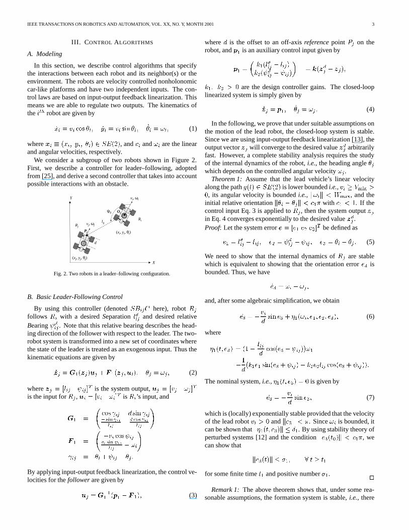
We consider a subgroup of two robots shown in Figure 2.First, we describe a controller for leader–following, adoptedfrom [25], and derive a second controller that takes into accountpossible interactions with an obstacle.
(xi, yi, θi)
l ij
vi, ωi
ψij
Ri
d
(xj, yj, θj)
vj, ωjRj
X
Y
Pj
Oi
Fig. 2. Two robots in a leader–following configuration.
B. Basic Leader-Following Control
By using this controller (denotedSBijC here), robotRjfollows Ri with a desiredSeparationldij and desired relativeBearing dij . Note that this relative bearing describes the head-ing direction of the follower with respect to the leader. The two-robot system is transformed into a new set of coordinates wherethe state of the leader is treated as an exogenous input. Thus thekinematic equations are given by_zj = G1(zj)uj + F 1(zj ;ui); �j = !j ; (2)
wherezj = [lij ij ]T is the system output,uj = [vj !j ]Tis the input forRj , ui = [vi !i]T isRi’s input, andG1 = cos ij d sin ij� sin ijlij d cos ijlij !F 1 = �vi cos ijvi sin ijlij � !i! ij = �i + ij � �j :By applying input-output feedback linearization, the control ve-locities for thefollowerare given byuj =G�11 (p1 � F 1); (3)
whered is the offset to an off-axisreferencepoint Pj on therobot, andp1 is an auxiliary control input given byp1 = � k1(ldij � lij)k2( dij � ij)� = k(zdj � zj);k1; k2 > 0 are the design controller gains. The closed-looplinearized system is simply given by_zj = p1; _�j = !j : (4)
In the following, we prove that under suitable assumptions onthe motion of the lead robot, the closed-loop system is stable.Since we are using input-output feedback linearization [13], theoutput vectorzj will converge to the desired valuezdj arbitrarilyfast. However, a complete stability analysis requires the studyof the internal dynamics of the robot,i.e., the heading angle�jwhich depends on the controlled angular velocity!j .
Theorem 1:Assume that the lead vehicle’s linear velocityalong the pathg(t) 2 SE(2) is lower boundedi.e., vi � Vmin >0, its angular velocity is boundedi.e., k!ik < Wmax, and theinitial relative orientationk�i � �jk < c1� with c1 < 1. If thecontrol input Eq. 3 is applied toRj , then the system outputzjin Eq. 4 converges exponentially to the desired valuezdj .Proof: Let the system errore = [e1 e2 e3]T be defined ase1 = ldij � lij ; e2 = dij � ij ; e3 = �i � �j : (5)
We need to show that the internal dynamics ofRj are stablewhich is equivalent to showing that the orientation errore3 isbounded. Thus, we have_e3 = !i � !j ;and, after some algebraic simplification, we obtain_e3 = �vid sin e3 + �1(!i; e1; e2; e3); (6)
where�1(t; e3) = (1� lijd cos(e3 + ij))!1�1d(k1e1 sin(e3 + ij) + k2e2lij cos(e3 + ij)):The nominal system,i.e., �1(t; e3) = 0 is given by_e3 = �vid sin e3; (7)
which is (locally) exponentially stable provided that the velocityof the lead robotvi > 0 andke3k < �. Since!i is bounded, itcan be shown thatk�1(t; e3)k � �1. By using stability theory ofperturbed systems [12] and the conditionke3(t0)k < c1�, wecan show that ke3(t)k � �1; 8 t � t1for some finite timet1 and positive number�1. 2
Remark 1:The above theorem shows that, under some rea-sonable assumptions, the formation system is stable,i.e., there
IEEE TRANSACTIONS ON ROBOTICS AND AUTOMATION, VOL. XX, NO. Y, MONTH 2001 4
exists a Lyapunov functionV (t; e) 2 [0;1) � D, whereD = fe 2 R3 j kek < cg and a positive numberc, such that_V (t; e) � 0. Lete12 = [e1 e2]T andV = eT12P 12e12 + 12e23 (8)
be a Lyapunov function for the system error Eq. 5. Then_V = �eT12Q12e12 � vid e3 sin e3 + �1(t; e3)e3 (9)
whereP 12 andQ12 are2� 2 positive definite matrices.By looking at Eq. 8-9, we can study some particular forma-
tions of practical interest. For example, if the leader travels ina straight line,i.e., !i = 0. It can be shown that the system is(locally) asymptotically stablei.e., e3 ! 0 ast ! 1 providedthatvi > 0 andke3k < �. If !i is constant (circular motion),thene3 is bounded. It is well-known that an optimal nonholo-nomic path can be planned by joining linear and circular trajec-tory segments. Hence any trajectory generated by such a plannerfor the leader will ensure stable leader-follower dynamics usingthe above controller.
This result can be extended ton robots in aconvoy-likefor-mation (c.f., [36]). Let us consider a team ofn robots whereRifollowsRi�1 underSBi�1;iC. Consider the Lyapunov functionV1:::n = nXi=2 eTi�1;iP i�1;iei�1;i + 12e2�i (10)
Its derivative is_V1:::n = � nXi=2(eTi�1;iQi�1;iei�1;i + vid e�i sin e�i � �i(t; e�i))(11)
whereei�1;i = [ldi�1;i�li�1;i �� i�1;i]T is the output error,ande�i = �i�1 � �i is the orientation error betweenRi�1 andRi. If the leader’s trajectory is well-behaved (same assumptionsas Theorem 1), then the convoy-like system can be shown to bestable.
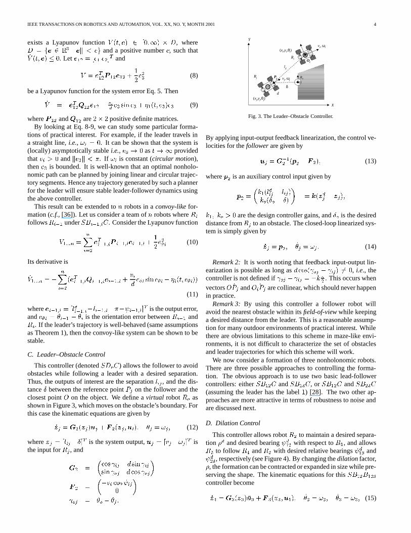
C. Leader–Obstacle Control
This controller (denotedSDoC) allows the follower to avoidobstacles while following a leader with a desired separation.Thus, the outputs of interest are the separationlij , and the dis-tance� between the reference pointPj on the follower and theclosest pointO on the object. We define avirtual robotRo asshown in Figure 3, which moves on the obstacle’s boundary. Forthis case the kinematic equations are given by_zj = G2(zj)uj + F 2(zj ;ui); �j = !j ; (12)
wherezj = [lij �]T is the system output,uj = [vj !j ]T isthe input forRj , andG2 = �cos ij d sin ijsin oj d cos oj�F 2 = ��vi cos ij0 � oj = �o � �j :
X
Y
d
(xi,yi,θi)
l ij
vi, ωi
(xj,yj,θj)
δ
vj, ωj
Ri
Rj RoPj
Oi
O
Fig. 3. The Leader–Obstacle Controller.
By applying input-output feedback linearization, the control ve-locities for thefollowerare given byuj =G�12 (p2 � F 2); (13)
wherep2 is an auxiliary control input given byp2 = �k1(ldij � lij)ko(�o � �) � = k(zdj � zj);k1; ko > 0 are the design controller gains, and�o is the desireddistance fromRj to an obstacle. The closed-loop linearized sys-tem is simply given by_zj = p2; _�j = !j : (14)
Remark 2: It is worth noting that feedback input-output lin-earization is possible as long asd cos( oj � ij) 6= 0, i.e., thecontroller is not defined if oj � ij = �k �2 . This occurs when
vectors ~OPj and ~OiPj are collinear, which should never happenin practice.
Remark 3:By using this controller a follower robot willavoid the nearest obstacle within itsfield-of-viewwhile keepinga desired distance from the leader. This is a reasonable assump-tion for many outdoor environments of practical interest. Whilethere are obvious limitations to this scheme in maze-like envi-ronments, it is not difficult to characterize the set of obstaclesand leader trajectories for which this scheme will work.
We now consider a formation of three nonholonomic robots.There are three possible approaches to controlling the forma-tion. The obvious approach is to use two basic lead-followercontrollers: eitherSB12C andSB13C, or SB12C andSB23C(assuming the leader has the label1) [28]. The two other ap-proaches are more attractive in terms of robustness to noise andare discussed next.
D. Dilation Control
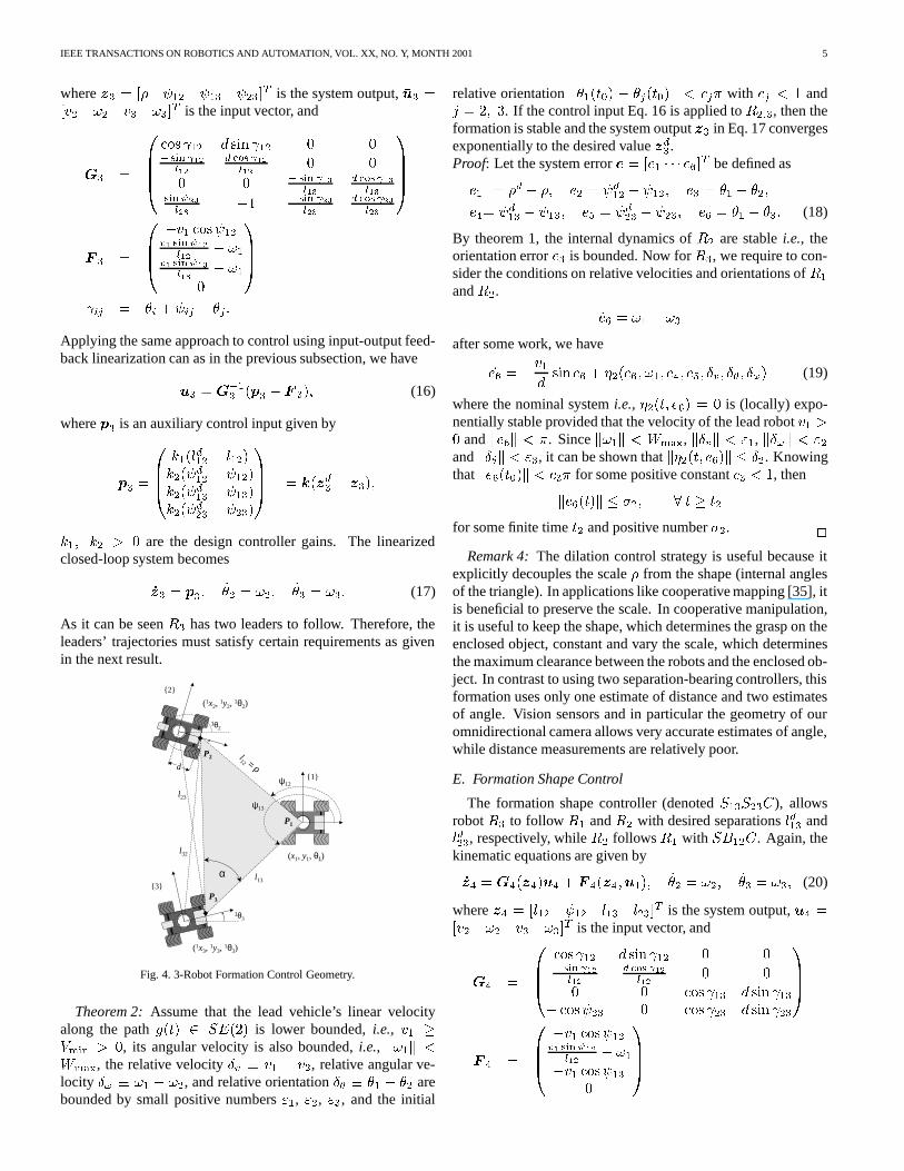
This controller allows robotR2 to maintain a desired separa-tion �d and desired bearing d12 with respect toR1, and allowsR3 to follow R1 andR2 with desired relative bearings d13 and d23, respectively (see Figure 4). By changing thedilation factor,�, the formation can be contracted or expanded in size while pre-serving the shape. The kinematic equations for thisSB12B123controller become_z3 =G3(z3)�u3 + F 3(z3;u1); _�2 = !2; _�3 = !3; (15)
IEEE TRANSACTIONS ON ROBOTICS AND AUTOMATION, VOL. XX, NO. Y, MONTH 2001 5
wherez3 = [� 12 13 23]T is the system output,�u3 =[v2 !2 v3 !3]T is the input vector, andG3 = 0BBB@ cos 12 d sin 12 0 0� sin 12l12 d cos 12l12 0 00 0 � sin 13l13 d cos 13l13sin 23l23 �1 � sin 23l23 d cos 23l23 1CCCAF 3 = 0BB@ �v1 cos 12v1 sin 12l12 � !1v1 sin 13l13 � !10 1CCA ij = �i + ij � �j :Applying the same approach to control using input-output feed-back linearization can as in the previous subsection, we have�u3 = G�13 (p3 � F 3); (16)
wherep3 is an auxiliary control input given byp3 = 0BB@ k1(ld12 � l12)k2( d12 � 12)k2( d13 � 13)k2( d23 � 23)1CCA = k(zd3 � z3);k1; k2 > 0 are the design controller gains. The linearizedclosed-loop system becomes_z3 = p3; _�2 = !2; _�3 = !3: (17)
As it can be seenR3 has two leaders to follow. Therefore, theleaders’ trajectories must satisfy certain requirements as givenin the next result.
{1}
(x1, y1, θ1)
{3}
1θ3
(1x3, 1y3, 1θ3)
(1x2, 1y2, 1θ2)
{2}
1θ2
l12 = ρ
α
d
l13
l23
l32
P1
P2
P3
ψ13
ψ12
Fig. 4. 3-Robot Formation Control Geometry.
Theorem 2:Assume that the lead vehicle’s linear velocityalong the pathg(t) 2 SE(2) is lower bounded,i.e., v1 �Vmin > 0, its angular velocity is also bounded,i.e., k!1k <Wmax, the relative velocity�v � v1 � v2, relative angular ve-locity �! � !1 � !2, and relative orientation�� � �1 � �2 arebounded by small positive numbers"1, "2, "3, and the initial
relative orientationk�1(t0) � �j(t0)k < cj� with cj < 1 andj = 2; 3. If the control input Eq. 16 is applied toR2;3, then theformation is stable and the system outputz3 in Eq. 17 convergesexponentially to the desired valuezd3.Proof: Let the system errore = [e1 � � � e6]T be defined ase1 = �d � �; e2 = d12 � 12; e3 = �1 � �2;e4= d13 � 13; e5 = d23 � 23; e6 = �1 � �3: (18)
By theorem 1, the internal dynamics ofR2 are stablei.e., theorientation errore3 is bounded. Now forR3, we require to con-sider the conditions on relative velocities and orientations ofR1andR2. _e6 = !1 � !3after some work, we have_e6 = �v1d sin e6 + �2(e6; !1; e4; e5; �v; ��; �!) (19)
where the nominal systemi.e., �2(t; e6) = 0 is (locally) expo-nentially stable provided that the velocity of the lead robotv1 >0 andke6k < �. Sincek!1k < Wmax, k�vk < "1, k�!k < "2andk��k < "3, it can be shown thatk�2(t; e6)k � �2. Knowingthatke6(t0)k < c3� for some positive constantc3 < 1, thenke6(t)k � �2; 8 t � t2for some finite timet2 and positive number�2. 2
Remark 4:The dilation control strategy is useful because itexplicitly decouples the scale� from the shape (internal anglesof the triangle). In applications like cooperative mapping [35], itis beneficial to preserve the scale. In cooperative manipulation,it is useful to keep the shape, which determines the grasp on theenclosed object, constant and vary the scale, which determinesthe maximum clearance between the robots and the enclosed ob-ject. In contrast to using two separation-bearing controllers, thisformation uses only one estimate of distance and two estimatesof angle. Vision sensors and in particular the geometry of ouromnidirectional camera allows very accurate estimates of angle,while distance measurements are relatively poor.
E. Formation Shape Control
The formation shape controller (denotedS13S23C), allowsrobotR3 to follow R1 andR2 with desired separationsld13 andld23, respectively, whileR2 followsR1 with SB12C. Again, thekinematic equations are given by_z4 =G4(z4)u4 + F 4(z4;u1); _�2 = !2; _�3 = !3; (20)
wherez4 = [l12 12 l13 l23]T is the system output,u4 =[v2 !2 v3 !3]T is the input vector, andG4 = 0BB@ cos 12 d sin 12 0 0� sin 12l12 d cos 12l12 0 00 0 cos 13 d sin 13� cos 23 0 cos 23 d sin 231CCAF 4 = 0BB@ �v1 cos 12v1 sin 12l12 � !1�v1 cos 130 1CCA
IEEE TRANSACTIONS ON ROBOTICS AND AUTOMATION, VOL. XX, NO. Y, MONTH 2001 6
By applying input-output feedback linearization, the control ve-locities for thefollower robots are given byu4 = G�14 (p4 � F 4) (21)
wherep4 is an auxiliary control input given byp4 = 0BB@ k1(ld12 � l12)k2( d12 � 12)k1(ld13 � l13)k1(ld23 � l23) 1CCA = k(zd4 � z4):The closed-loop linearized system is given by_z4 = p4; _�2 = !2; _�3 = !3: (22)
As before, we will show that the closed-loop system is stable,and the robots navigate keeping formation.
Theorem 3:Assume that the lead vehicle’s linear velocityalong the pathg(t) 2 SE(2) is lower boundedi.e., v1 � Vmin >0, its angular velocity is also boundedi.e., k!1k < Wmax,the relative velocity�v � v1 � v2 and relative orientation�� � �1 � �2 are bounded by small positive numbers"1, "2,and the initial relative orientationk�1 � �jk < cj� with cj < 1andj = 2; 3. If the control input Eq. 21 is applied toR2;3,then the formation is stable and the system outputz4 in Eq. 22converges exponentially to the desired valuezd4.
The proof is similar to Theorem 2.Remark 5: In contrast to the previous two three-robot forma-
tion controllers, this controller allows explicit control of all sep-arations and minimizes the risk for collisions. This controlleris preferred when the separations between robots are small, andwhen, coincidentally, the estimates of distance through visionare better.
IV. COORDINATION PROTOCOL
A. Choice of Formations
In Section III, we have shown that under certain assumptionsa group of robots can navigate maintaining a stable formation.However, in real situations mobile robotic systems are subject tosensor, actuator and communication constraints, and have to op-erate within unstructured environments. We describe aswitch-ing paradigmthat allows robots to select the most appropriatecontroller (formation) depending on the environment.
In this work, we model the group ofn autonomous mobilerobots as a tupleF = (g; r;H) whereg(t) 2 SE(2) is the ref-erence trajectory of the lead robot,r is a set ofshapevectorsdescribing the relative positions of each vehicle with respect tothe reference formation framefMg, andH is a control graphwhere nodes represent robots and edges represent relations be-tween nodes (see details in following subsection) [25]. Thus,F describes a dynamical system evolving in continuous-timeon the intervalT = [t0; tN ] � R+ in the configuration spaceC = SE(2)n. Without loss of generality, the formation refer-ence framefMg is fixed to the lead robot; however, it is not arequirement in our method. Sometimes it is necessary to addvirtual robots to the group to represent either moving targets, ortrajectories that are along such features as walls, lanes, or obsta-cles. While this results in a change inF , it does not change theconfiguration space of the system.
The control graphs describing the formation are designedfrom the basic controllers described in the previous section. Theenumeration of control graphs forn robots is discussed in [28].LetUj = f�1;j ; : : : ; �p;jg be the set of available controllers forrobotRj . We consider the problem of selecting the controller,�k;j 2 Uj for robotRj , assuming that the controllers for robotsR2; R3; : : : ; Rj�1 have been specified.
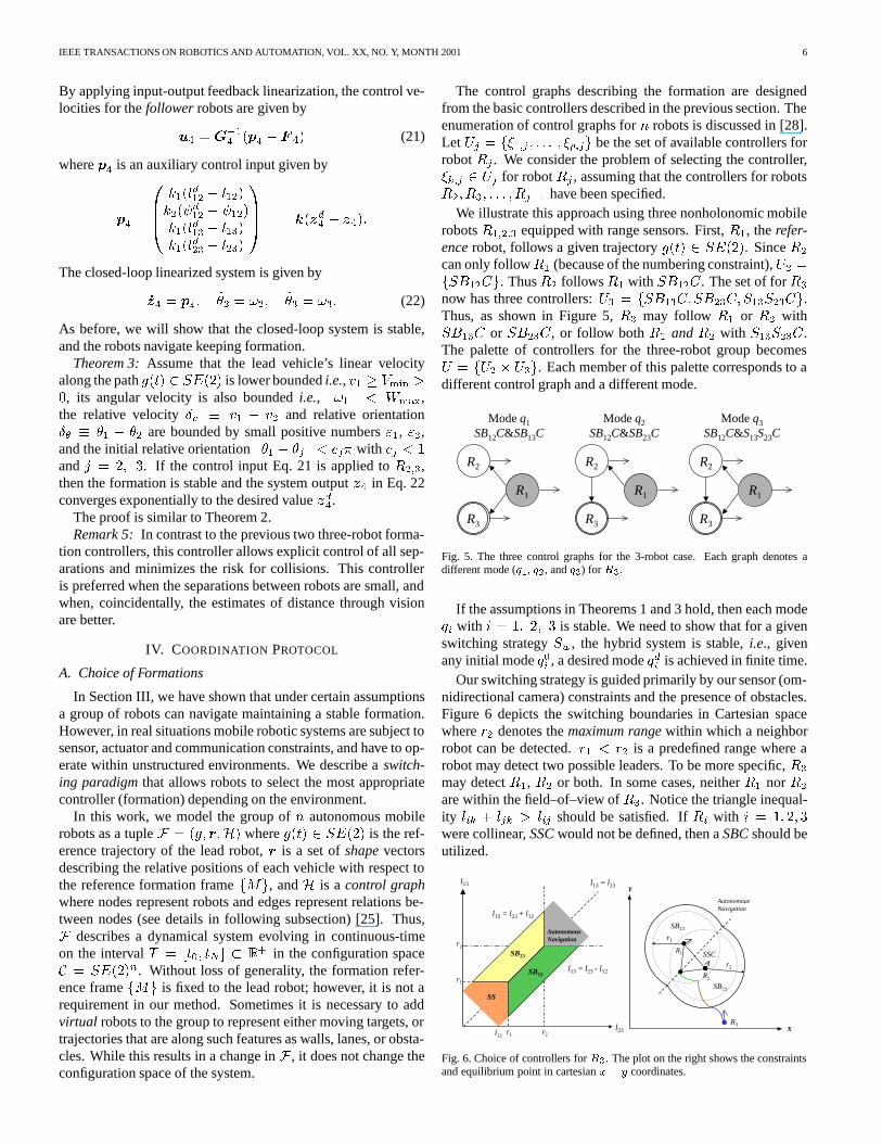
We illustrate this approach using three nonholonomic mobilerobotsR1;2;3 equipped with range sensors. First,R1, therefer-encerobot, follows a given trajectoryg(t) 2 SE(2). SinceR2can only followR1 (because of the numbering constraint),U2 =fSB12Cg. ThusR2 followsR1 with SB12C. The set of forR3now has three controllers:U3 = fSB13C; SB23C; S13S23Cg.Thus, as shown in Figure 5,R3 may follow R1 or R2 withSB13C or SB23C, or follow bothR1 andR2 with S13S23C.The palette of controllers for the three-robot group becomesU = fU2 � U3g. Each member of this palette corresponds to adifferent control graph and a different mode.
Mode q1SB12C&SB13C
Mode q2SB12C&SB23C
Mode q3SB12C&S13S23C
R1
R2
R3
R1
R2
R3
R1
R2
R3
Fig. 5. The three control graphs for the 3-robot case. Each graph denotes adifferent mode (q1, q2, andq3) for R3.
If the assumptions in Theorems 1 and 3 hold, then each modeqi with i = 1; 2; 3 is stable. We need to show that for a givenswitching strategySw, the hybrid system is stable,i.e., givenany initial modeq0i , a desired modeqdi is achieved in finite time.
Our switching strategy is guided primarily by our sensor (om-nidirectional camera) constraints and the presence of obstacles.Figure 6 depicts the switching boundaries in Cartesian spacewherer2 denotes themaximum rangewithin which a neighborrobot can be detected.r1 < r2 is a predefined range where arobot may detect two possible leaders. To be more specific,R3may detectR1, R2 or both. In some cases, neitherR1 norR2are within the field–of–view ofR3. Notice the triangle inequal-ity lik + ljk > lij should be satisfied. IfRi with i = 1; 2; 3were collinear,SSCwould not be defined, then aSBCshould beutilized.
l12l23r1 r2
r1
r2
l13
SB13
SS
l13 = l23
l13 = l23 + l12
l13 = l23 - l12
AutonomousNavigation
SB23
AutonomousNavigation
X
Y
SB23
SB13
SSCR1
R2
r1
r2
R3
Fig. 6. Choice of controllers forR3. The plot on the right shows the constraintsand equilibrium point in cartesianx� y coordinates.
IEEE TRANSACTIONS ON ROBOTICS AND AUTOMATION, VOL. XX, NO. Y, MONTH 2001 7
The formation control objective is to driveR3 to a regionwhere it can detect bothR1 andR2. Thus, the switching controlstrategy forR3 can be summarized as follows
If (l13 < l23)&(l23 > r1)&(l13 < r2) Then SB13CIf (l13 > l23)&(l13 > r1)&(l23 < r2) Then SB23C
If (l13 < r1)&(l23 < r1) Then S13S23CIf (l13 > r2)&(l23 > r2) Then AutonNavig
The set of control behaviors that a robot may exhibit when thereis no leader within its field-of–view is calledAutonomous Navi-gationhere.
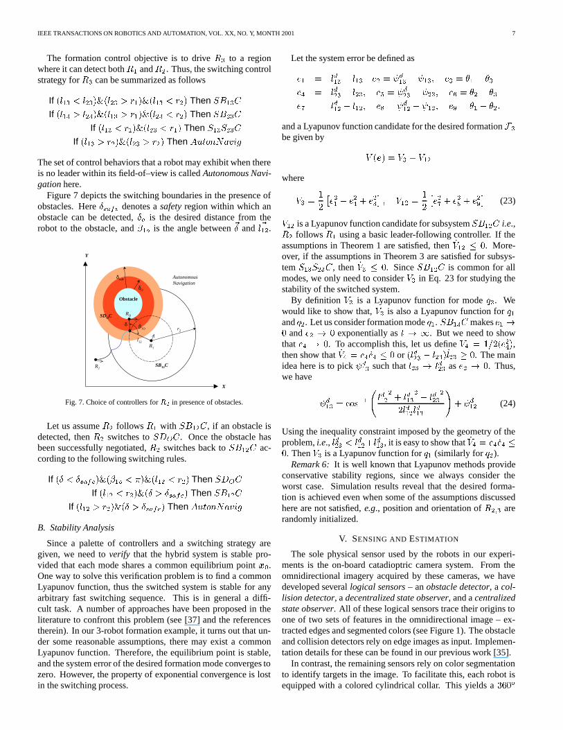
Figure 7 depicts the switching boundaries in the presence ofobstacles. Here�safe denotes asafetyregion within which anobstacle can be detected,�o is the desired distance from therobot to the obstacle, and�1o is the angle between~� and ~l12.
AutonomousNavigation
X
Y
r2
R1
Obstacle
R2SB12C
SDOC
δsafe
l12
δO
δ
RO
β1O
Fig. 7. Choice of controllers forR2 in presence of obstacles.
Let us assumeR2 followsR1 with SB12C, if an obstacle isdetected, thenR2 switches toSDOC. Once the obstacle hasbeen successfully negotiated,R2 switches back toSB12C ac-cording to the following switching rules.
If (� < �safe)&(�1o < �)&(l12 < r2) Then SDOCIf (l12 < r2)&(� > �safe) Then SB12C
If (l12 > r2)&(� > �safe) Then AutonNavigB. Stability Analysis
Since a palette of controllers and a switching strategy aregiven, we need toverify that the hybrid system is stable pro-vided that each mode shares a common equilibrium pointx0.One way to solve this verification problem is to find a commonLyapunov function, thus the switched system is stable for anyarbitrary fast switching sequence. This is in general a diffi-cult task. A number of approaches have been proposed in theliterature to confront this problem (see [37] and the referencestherein). In our 3-robot formation example, it turns out that un-der some reasonable assumptions, there may exist a commonLyapunov function. Therefore, the equilibrium point is stable,and the system error of the desired formation mode converges tozero. However, the property of exponential convergence is lostin the switching process.
Let the system error be defined ase1 = ld13 � l13 e2 = d13 � 13; e3 = �1 � �3e4 = ld23 � l23; e5 = d23 � 23; e6 = �2 � �3e7 = ld12 � l12; e8 = d12 � 12; e9 = �1 � �2;and a Lyapunov function candidate for the desired formationF3be given by V (e) = V3 + V12whereV3 = 12 �e21 + e24 + e23� ; V12 = 12 �e27 + e28 + e29� (23)V12 is a Lyapunov function candidate for subsystemSB12C i.e.,R2 followsR1 using a basic leader-following controller. If theassumptions in Theorem 1 are satisfied, then_V12 � 0. More-over, if the assumptions in Theorem 3 are satisfied for subsys-temS13S23C, then _V3 � 0. SinceSB12C is common for allmodes, we only need to considerV3 in Eq. 23 for studying thestability of the switched system.
By definition V3 is a Lyapunov function for modeq3. Wewould like to show that,V3 is also a Lyapunov function forq1andq2. Let us consider formation modeq1. SB13C makese1 !0 ande2 ! 0 exponentially ast ! 1. But we need to showthat e4 ! 0. To accomplish this, let us defineV4 = 1=2(e24),then show that_V4 = e4 _e4 � 0 or (ld23 � l23) _l23 � 0. The mainidea here is to pick d13 such thatl23 ! ld23 ase2 ! 0. Thus,we have d13 = cos�1 ld122 + ld132 � ld2322ld12ld13 !+ d12 (24)
Using the inequality constraint imposed by the geometry of theproblem,i.e., ld23 < ld12+ld13, it is easy to show that_V4 = e4 _e4 �0. ThenV3 is a Lyapunov function forq1 (similarly for q2).
Remark 6: It is well known that Lyapunov methods provideconservative stability regions, since we always consider theworst case. Simulation results reveal that the desired forma-tion is achieved even when some of the assumptions discussedhere are not satisfied,e.g., position and orientation ofR2;3 arerandomly initialized.
V. SENSING AND ESTIMATION
The sole physical sensor used by the robots in our experi-ments is the on-board catadioptric camera system. From theomnidirectional imagery acquired by these cameras, we havedeveloped severallogical sensors– anobstacle detector, acol-lision detector, adecentralized state observer, and acentralizedstate observer. All of these logical sensors trace their origins toone of two sets of features in the omnidirectional image – ex-tracted edges and segmented colors (see Figure 1). The obstacleand collision detectors rely on edge images as input. Implemen-tation details for these can be found in our previous work [35].
In contrast, the remaining sensors rely on color segmentationto identify targets in the image. To facilitate this, each robot isequipped with a colored cylindrical collar. This yields a360�
IEEE TRANSACTIONS ON ROBOTICS AND AUTOMATION, VOL. XX, NO. Y, MONTH 2001 8
symmetrical target about each robot’s optical axis. We then seg-ment the image for these colors by using an extractor operatingin YUV colorspace. Our implementation takes advantage of YUand YV look-up tables to significantly reduce processing time,and segments up to 8 colors simultaneously. By applying a blobextractor to the color segmented image, each robot is able toisolate teammates within its own image.
Next, we exploit the characteristics of the omnidirectionalcameras. One of their primary advantages in this application isthat catadioptric camera systems afford a single effective pointof projection. This means that, after an appropriate calibration,every point in the omnidirectional image can be associated witha unique ray through the focal point of the camera. As a re-sult, by taking the center of gravity (CG) of the extracted collarsin the color segmented image, each robot can compute reliableestimates of the direction vectors to its teammates. These di-rections provide the basis for both centralized and decentralizedstate observation.
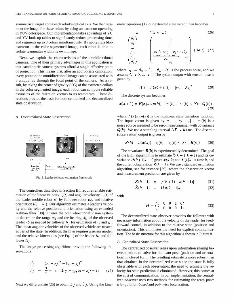
A. Decentralized State Observation
Fig. 8. Leader-follower estimation framework
The controllers described in Section III, require reliable esti-mation of the linear velocityvi(t) and angular velocity!i(t) ofthe leader mobile robotRi by follower robotRj , and relativeorientation (�i � �j). Our algorithm estimates a leader’s veloc-ity and the relative position and orientation using an extendedKalman filter [38]. It uses the omni-directional vision systemto determine the range�ij and the bearing�ij of the observedleaderRi as needed by followerRj for estimation ofvi andwi.The linear angular velocities of the observed vehicle are treatedas part of the state. In addition, the filter requires a sensor model,and the relative kinematics (see Eq. 1) of the leaderRi and fol-lowerRj .
The image processing algorithms provide the following ob-servations�2ij = (xi � xj)2 + (yi � yj)2�ij = �2 + a tan 2(yi � yj ; xi � xj)� �j (25)
Next we differentiate (25) to obtain_�ij and _�ij . Using the kine-
matic equations (1), our extended state vector then becomes_�x = f(�x;u;w) (26)0BBBBBB@ _�i_vi_!i_�ij_�ij_�j1CCCCCCA = 0BBBBBB@ !i00vi sin�ij � vj sin�ijvi cos�ij�vj cos �ij�ij � !j!j
1CCCCCCA+w(t) (27)
where�ij = �ij + �j � �i, w(t) is the process noise, and weassume_vi � 0; _wi � 0. The system output with sensor noise isgiven by z(t) = h(�x) + �(t) = [�ij �ij ]T (28)
The discrete system becomes�x(k + 1) = F (�x(k);u(k)) +w(k); w(k) � N(0;Q(k))(29)
whereF (�x(k),u(k)) is the nonlinear state transition function.The input vector is given byu = [vj !j ]T . w(k) is anoise source assumed to be zero-mean Gaussian with covarianceQ(k). We use a sampling interval�T � 50 ms. The discrete(observation) output is given byZ(k) = h(�x(k)) + �(k); �(k) � N(0;R(k)) (30)
The covarianceR(k) is experimentally determined. The goalof the EKF algorithm is to estimate�x(k + 1jk + 1) and its co-varianceP (k+1jk+1) given �x(kjk) andP (kjk) at timek, andthe current observationZ(k + 1). We use a standard estimationalgorithm, see for instance [39], where the observation vectorand measurement prediction are given byZ(k + 1) = [�(k + 1) �(k + 1)]T (31)Z(k + 1) = H �x(k + 1jk) (32)
with H = �0 0 0 1 00 0 0 0 1� (33)
The decentralized state observer provides the follower withnecessary information about the velocity of the leader for feed-forward control, in addition to the relative state (position andorientation). This eliminates the need for explicit communica-tion. The basic structure for this algorithm is shown in Figure 8.
B. Centralized State Observation
The centralized observer relies upon information sharing be-tween robots to solve for the team pose (position and orienta-tion) in closed form. The resulting estimate is more robust thanthat obtained in the decentralized case since the state is fullyobservable with each observation; the need to estimate the ve-locity for state prediction is eliminated. However, this comes atthe cost of communication. In our implementation, the central-ized observer uses two methods for estimating the team pose:triangulation-basedandpair-wiselocalization.
IEEE TRANSACTIONS ON ROBOTICS AND AUTOMATION, VOL. XX, NO. Y, MONTH 2001 9
z1
y1
x1
z3y3
x3
z2
y2
x2
Frame 1
Frame 2(1T2, 1R2)
Frame 3(1T3, 1R3)
13
2
L23
L13
L12
û12
û13
û21û23
û32
û31
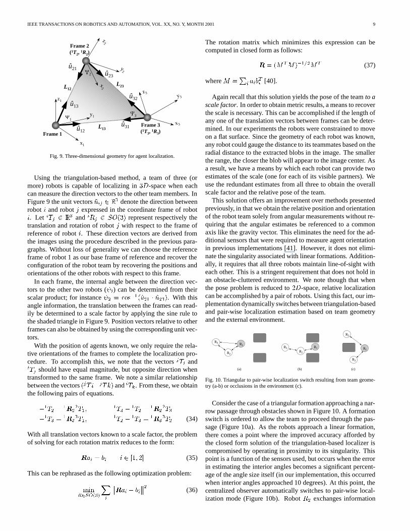
Fig. 9. Three-dimensional geometry for agent localization.
Using the triangulation-based method, a team of three (ormore) robots is capable of localizing in3D-space when eachcan measure the direction vectors to the other team members. InFigure 9 the unit vectorsuij 2 R3 denote the direction betweenrobot i and robotj expressed in the coordinate frame of roboti. Let iTj 2 R3 and iRj 2 SO(3) represent respectively thetranslation and rotation of robotj with respect to the frame ofreference of roboti. These direction vectors are derived fromthe images using the procedure described in the previous para-graphs. Without loss of generality we can choose the referenceframe of robot 1 as our base frame of reference and recover theconfiguration of the robot team by recovering the positions andorientations of the other robots with respect to this frame.
In each frame, the internal angle between the direction vec-tors to the other two robots ( i) can be determined from theirscalar product; for instance 2 = cos�1(u21 � u23). With thisangle information, the translation between the frames can read-ily be determined to a scale factor by applying the sine rule tothe shaded triangle in Figure 9. Position vectors relative to otherframes can also be obtained by using the corresponding unit vec-tors.
With the position of agents known, we only require the rela-tive orientations of the frames to complete the localization pro-cedure. To accomplish this, we note that the vectorsjTi andiTj should have equal magnitude, but opposite direction whentransformed to the same frame. We note a similar relationshipbetween the vectors(jT i�jTk) andiTk. From these, we obtainthe following pairs of equations.�1T2 = 1R22T1; 1T3 � 1T2 = 1R22T3�1T3 = 1R33T1; 1T2 � 1T3 = 1R33T2 (34)
With all translation vectors known to a scale factor, the problemof solving for each rotation matrix reduces to the form:Rai = bi i 2 [1; 2] (35)
This can be rephrased as the following optimization problem:minR2SO(3)Xi Rai � bi 2 (36)
The rotation matrix which minimizes this expression can becomputed in closed form as follows:R = (MTM)�1=2MT (37)
whereM =Pi aibTi [40].
Again recall that this solution yields the pose of the teamto ascale factor. In order to obtain metric results, a means to recoverthe scale is necessary. This can be accomplished if the length ofany one of the translation vectors between frames can be deter-mined. In our experiments the robots were constrained to moveon a flat surface. Since the geometry of each robot was known,any robot could gauge the distance to its teammates based on theradial distance to the extracted blobs in the image. The smallerthe range, the closer the blob will appear to the image center. Asa result, we have a means by which each robot can provide twoestimates of the scale (one for each of its visible partners). Weuse the redundant estimates from all three to obtain the overallscale factor and the relative pose of the team.
This solution offers an improvement over methods presentedpreviously, in that we obtain the relative position and orientationof the robot team solely from angular measurements without re-quiring that the angular estimates be referenced to a commonaxis like the gravity vector. This eliminates the need for the ad-ditional sensors that were required to measure agent orientationin previous implementations [41]. However, it does not elimi-nate the singularity associated with linear formations. Addition-ally, it requires that all three robots maintain line-of-sight witheach other. This is a stringent requirement that does not hold inan obstacle-cluttered environment. We note though that whenthe pose problem is reduced to2D-space, relative localizationcan be accomplished by a pair of robots. Using this fact, our im-plementation dynamically switches between triangulation-basedand pair-wise localization estimation based on team geometryand the external environment.
1
R1R
R
2
1
3
R3
2R
R
3R2
RR
(c)(a) (b)
Fig. 10. Triangular to pair-wise localization switch resulting from team geome-try (a-b) or occlusions in the environment (c).
Consider the case of a triangular formation approaching a nar-row passage through obstacles shown in Figure 10. A formationswitch is ordered to allow the team to proceed through the pas-sage (Figure 10a). As the robots approach a linear formation,there comes a point where the improved accuracy afforded bythe closed form solution of the triangulation-based localizer iscompromised by operating in proximity to its singularity. Thispoint is a function of the sensors used, but occurs when the errorin estimating the interior angles becomes a significant percent-age of the angle size itself (in our implementation, this occurredwhen interior angles approached 10 degrees). At this point, thecentralized observer automatically switches to pair-wise local-ization mode (Figure 10b). RobotR2 exchanges information

IEEE TRANSACTIONS ON ROBOTICS AND AUTOMATION, VOL. XX, NO. Y, MONTH 2001 10
with the team leader(R1) to localize relative to the leader’sframe. R3 performs a similar exchange withR2, obtains a lo-calization estimate relative toR2, and as a result determines itspose relative toR1.
While this mode switch resulted from the formation geome-try, it can also be directly triggered by the environment. This isshown in Figure 10c, where the line-of-sight between two robotsis occluded by an obstacle. This occlusion can be detected froma global visibility matrix, resulting in a pair-wise localizationswitch.
The pair-wise method serves as the secondary localizationmode for the centralized observer. In most formation geome-tries, the constraint obtained by determining the relative forma-tion scale – along with the redundant range measurements forestimating the absolute scale – result in improved performancein the triangulation-based mode. Mean range errors were typi-cally 3-5%, compared to 10% for the pair-wise case.
The advantages resulting from this internal switching aretwofold. It allows the centralized observer to robustly estimatethe team state regardless of formation geometry. Additionally,it allows the team to react to an obstacle-cluttered environmentwith only a slight degradation in accuracy. Since the observerprovides only state estimates for use by the controller modes,the switching is transparent to all users.
VI. RESULTS
A. Simulation of Switching Strategy
−2 0 2 4 6 8 10
0
2
4
6
8
10
12
14
Y (
m)
X (m)
1 2
3
1
2
3
2
3
1
Fig. 11. The leader follows a sinusoidal trajectory while followers switch toavoid obstacle while maintaining desired triangle formation.
In Section IV, we discussed choosing formations and switch-ing strategies for maintaining formation shape whilst ensuringa stable switched system. Here, we illustrate the application ofthese concepts to a simulation of3 nonholonomic robots withone obstacle (Figure 11). RobotR1 is the lead robot, and thedesired shape is a triangle. The control mode switching inR2andR3 are shown in Figure 12. The formation shape is achievedand the robots successfully negotiate the obstacle.
0 5 10 15 20 25 300
1
2
Control Modes for R2: SB12
= 1, S12
DO
= 2
Time (s)0 5 10 15 20 25 30
0
1
2
3
Control Modes for R3: SB13
= 1, SB23
= 2, S13
S23
= 3
Time (s)
Fig. 12. Mode switching for robotR2 (left plot) andR3 (right plot) for trajec-tories in Figure 11. The numbering of the modes are shown on the top of eachplot.
B. Experiments
B.1 Hardware Platform
The cooperative control framework was implemented on theGRASP Lab’s ClodbusterTM (CB) robots. The CB platform isbased on the Tamiya ClodbusterTM radio controlled1=10 scalemodel truck. Each CB is equipped with an omnidirectional cam-era (described in Section V) as its sole sensor [42]. The platformlacks on-board processing. As a result, video signals from thecamera on-board are sent to a remote computer for processingvia a wireless 2.4 GHz video transmitter. Velocity and headingcontrol signals are sent from the host computer to the vehiclesas necessary. This reduces the cost and size of the platform,and makes it simple to coordinate the data processing and con-trol operations. Note that each robot can be independently con-trolled using different host computers. The CB team used forour multi-robot coordination experiments can be seen in Figure13.
Omni-Camera
Video transmitter
Collar foridentification
Fig. 13. The ClodbusterTM team used for experiments.
B.2 Formation Control
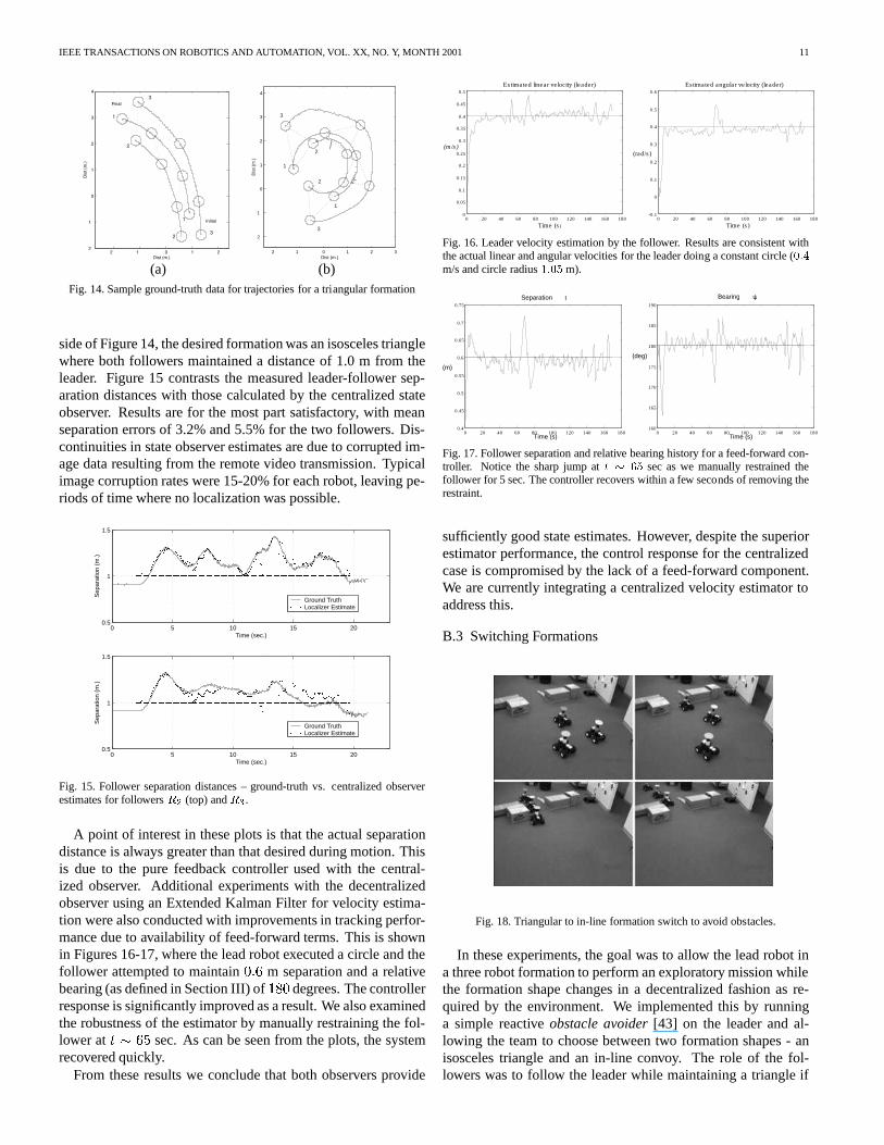
Initial experiments in formation control were intended to val-idate the dynamic state estimation implementation and corre-sponding control approach. As a result, experiments first exam-ined stable formations following trajectories of straight lines,gradual arcs and circles. Video data from these trials wererecorded using a calibrated overhead camera. This allowed“ground-truth” position data of the formation to be recorded andanalyzed off-line together with the state observer position esti-mates. Ground plane trajectories from a pair of representativetrials can be found in Figure 14.
We next compared the state observer estimates with theground-truth position data. As an example, in the trial on the left
IEEE TRANSACTIONS ON ROBOTICS AND AUTOMATION, VOL. XX, NO. Y, MONTH 2001 11
2 1 0 1 22
1
0
1
2
3
4
Dist (m.)
Dis
t (m
.)
Initial
Final
1
2
3
1
23
(a)2 1 0 1 2 3
2
1
0
1
2
3
4
Dist (m.)D
ist (
m.)
1
2
3
1
2
3
(b)Fig. 14. Sample ground-truth data for trajectories for a triangular formation
side of Figure 14, the desired formation was an isosceles trianglewhere both followers maintained a distance of 1.0 m from theleader. Figure 15 contrasts the measured leader-follower sep-aration distances with those calculated by the centralized stateobserver. Results are for the most part satisfactory, with meanseparation errors of 3.2% and 5.5% for the two followers. Dis-continuities in state observer estimates are due to corrupted im-age data resulting from the remote video transmission. Typicalimage corruption rates were 15-20% for each robot, leaving pe-riods of time where no localization was possible.
0 5 10 15 200.5
1
1.5
Time (sec.)
Sep
arat
ion
(m.)
Ground Truth Localizer Estimate
0 5 10 15 200.5
1
1.5
Time (sec.)
Sep
arat
ion
(m.)
Ground Truth Localizer Estimate
Fig. 15. Follower separation distances – ground-truth vs. centralized observerestimates for followersR2 (top) andR3.
A point of interest in these plots is that the actual separationdistance is always greater than that desired during motion. Thisis due to the pure feedback controller used with the central-ized observer. Additional experiments with the decentralizedobserver using an Extended Kalman Filter for velocity estima-tion were also conducted with improvements in tracking perfor-mance due to availability of feed-forward terms. This is shownin Figures 16-17, where the lead robot executed a circle and thefollower attempted to maintain0:6 m separation and a relativebearing (as defined in Section III) of180 degrees. The controllerresponse is significantly improved as a result. We also examinedthe robustness of the estimator by manually restraining the fol-lower att � 65 sec. As can be seen from the plots, the systemrecovered quickly.
From these results we conclude that both observers provide
0 20 40 60 80 100 120 140 160 1800
0.05
0.1
0.15
0.2
0.25
0.3
0.35
0.4
0.45
0.5
Estimated linear ve locity (leader)
(m/s)
Time (s)
0 20 40 60 80 100 120 140 160 180-0.1
0
0.1
0.2
0.3
0.4
0.5
0.6
Estimated angular ve locity (leader)
(rad/s )
Time (s )
Fig. 16. Leader velocity estimation by the follower. Results are consistent withthe actual linear and angular velocities for the leader doing a constant circle (0:4m/s and circle radius1:05 m).
0 20 40 60 80 100 120 140 160 1800.4
0.45
0.5
0.55
0.6
0.65
0.7
0.75
Separation l
(m)
Time (s)0 20 40 60 80 100 120 140 160 180
160
165
170
175
180
185
190
Bearing ψ
(deg)
Time (s)
Fig. 17. Follower separation and relative bearing history for a feed-forward con-troller. Notice the sharp jump att � 65 sec as we manually restrained thefollower for 5 sec. The controller recovers within a few seconds of removing therestraint.
sufficiently good state estimates. However, despite the superiorestimator performance, the control response for the centralizedcase is compromised by the lack of a feed-forward component.We are currently integrating a centralized velocity estimator toaddress this.
B.3 Switching Formations
Fig. 18. Triangular to in-line formation switch to avoid obstacles.
In these experiments, the goal was to allow the lead robot ina three robot formation to perform an exploratory mission whilethe formation shape changes in a decentralized fashion as re-quired by the environment. We implemented this by runninga simple reactiveobstacle avoider[43] on the leader and al-lowing the team to choose between two formation shapes - anisosceles triangle and an in-line convoy. The role of the fol-lowers was to follow the leader while maintaining a triangle if
IEEE TRANSACTIONS ON ROBOTICS AND AUTOMATION, VOL. XX, NO. Y, MONTH 2001 12
−2 −1 0 1 2 3−2
−1
0
1
2
3
4
Dist (m.)
Dis
t (m
.)
1
2
3
1
2
3
−2.5 −1.5 −0.5 0.5 1.5 2.5−2
−1
0
1
2
3
4
Dist (m.)
Dis
t (m
.)
1
3
1
2
3
2
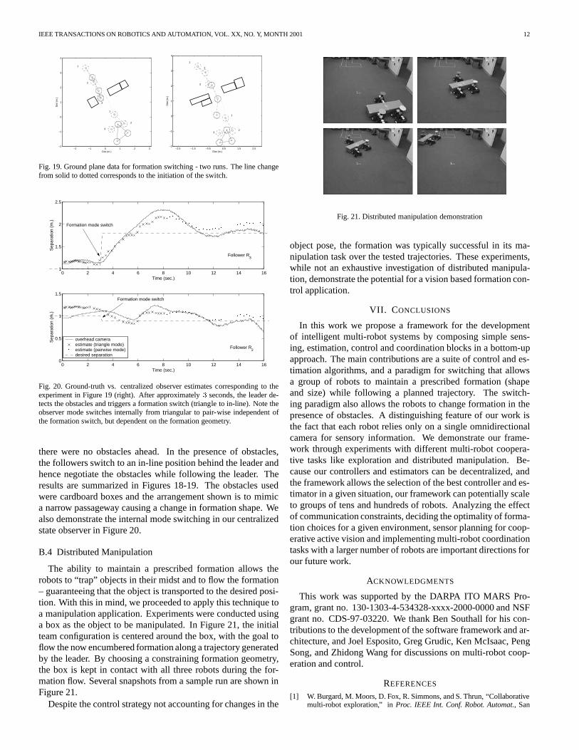
Fig. 19. Ground plane data for formation switching - two runs. The line changefrom solid to dotted corresponds to the initiation of the switch.
0 2 4 6 8 10 12 14 161
1.5
2
2.5
Time (sec.)
Sep
arat
ion
(m.)
Follower R3
0 2 4 6 8 10 12 14 160
0.5
1
1.5
Time (sec.)
Sep
arat
ion
(m.)
Follower R2
overhead camera estimate (triangle mode)estimate (pairwise mode)desired separation
Formation mode switch
Formation mode switch
Fig. 20. Ground-truth vs. centralized observer estimates corresponding to theexperiment in Figure 19 (right). After approximately3 seconds, the leader de-tects the obstacles and triggers a formation switch (triangle to in-line). Note theobserver mode switches internally from triangular to pair-wise independent ofthe formation switch, but dependent on the formation geometry.
there were no obstacles ahead. In the presence of obstacles,the followers switch to an in-line position behind the leader andhence negotiate the obstacles while following the leader. Theresults are summarized in Figures 18-19. The obstacles usedwere cardboard boxes and the arrangement shown is to mimica narrow passageway causing a change in formation shape. Wealso demonstrate the internal mode switching in our centralizedstate observer in Figure 20.
B.4 Distributed Manipulation
The ability to maintain a prescribed formation allows therobots to “trap” objects in their midst and to flow the formation– guaranteeing that the object is transported to the desired posi-tion. With this in mind, we proceeded to apply this technique toa manipulation application. Experiments were conducted usinga box as the object to be manipulated. In Figure 21, the initialteam configuration is centered around the box, with the goal toflow the now encumbered formation along a trajectory generatedby the leader. By choosing a constraining formation geometry,the box is kept in contact with all three robots during the for-mation flow. Several snapshots from a sample run are shown inFigure 21.
Despite the control strategy not accounting for changes in the
Fig. 21. Distributed manipulation demonstration
object pose, the formation was typically successful in its ma-nipulation task over the tested trajectories. These experiments,while not an exhaustive investigation of distributed manipula-tion, demonstrate the potential for a vision based formation con-trol application.
VII. CONCLUSIONS
In this work we propose a framework for the developmentof intelligent multi-robot systems by composing simple sens-ing, estimation, control and coordination blocks in a bottom-upapproach. The main contributions are a suite of control and es-timation algorithms, and a paradigm for switching that allowsa group of robots to maintain a prescribed formation (shapeand size) while following a planned trajectory. The switch-ing paradigm also allows the robots to change formation in thepresence of obstacles. A distinguishing feature of our work isthe fact that each robot relies only on a single omnidirectionalcamera for sensory information. We demonstrate our frame-work through experiments with different multi-robot coopera-tive tasks like exploration and distributed manipulation. Be-cause our controllers and estimators can be decentralized, andthe framework allows the selection of the best controller and es-timator in a given situation, our framework can potentially scaleto groups of tens and hundreds of robots. Analyzing the effectof communication constraints, deciding the optimality of forma-tion choices for a given environment, sensor planning for coop-erative active vision and implementing multi-robot coordinationtasks with a larger number of robots are important directions forour future work.
ACKNOWLEDGMENTS
This work was supported by the DARPA ITO MARS Pro-gram, grant no. 130-1303-4-534328-xxxx-2000-0000 and NSFgrant no. CDS-97-03220. We thank Ben Southall for his con-tributions to the development of the software framework and ar-chitecture, and Joel Esposito, Greg Grudic, Ken McIsaac, PengSong, and Zhidong Wang for discussions on multi-robot coop-eration and control.
REFERENCES
[1] W. Burgard, M. Moors, D. Fox, R. Simmons, and S. Thrun, “Collaborativemulti-robot exploration,” inProc. IEEE Int. Conf. Robot. Automat., San
IEEE TRANSACTIONS ON ROBOTICS AND AUTOMATION, VOL. XX, NO. Y, MONTH 2001 13
Francisco, CA, April 2000, pp. 476–481.[2] J. Feddema and D. Schoenwald, “Decentralized control ofcooperative
robotic vehicles,” inProc. SPIE Vol. 4364, Aerosense, Orlando, Florida,April 2001.
[3] J. S. Jennings, G. Whelan, and W. F. Evans, “Cooperative search andrescue with a team of mobile robots,”Proc. IEEE Int. Conf. on AdvancedRobotics, 1997.
[4] C. J. Taylor, “Videoplus: A method for capturing the structure and appear-ance of immersive environment,”Second Workshop on 3D Structure fromMultiple Images of Large-scale Environments, 2000.
[5] L. Iochhi, K. Konolige, and M. Bayracharya, “A frameworkand archi-tecture for multi-robot coordination,” inProc. Seventh Int. Symposium onExperimental Robotics (ISER), Honolulu, Hawaii, Dec. 2000.
[6] D. Rus, B. Donald, and J. Jennings, “Moving furniture with teams of au-tonomous robots,” inIEEE/RSJ International Conf. on Intelligent Robotsand Systems, Pittsburgh, PA, Aug 1995, pp. 235–242.
[7] M. Mataric, M. Nilsson, and K. Simsarian, “Cooperative multi-robot boxpushing,” inIEEE/RSJ International Conf. on Intelligent Robots and Sys-tems, Pittsburgh, PA, Aug 1995, pp. 556–561.
[8] D. Stilwell and J. Bay, “Toward the development of a material transportsystem using swarms of ant-like robots,” inIEEE International Conf. onRobotics and Automation, Atlanta, GA, May 1993, pp. 766–771.
[9] T. Sugar and V. Kumar, “Control and coordination of multiple mobilerobots in manipulation and material handling tasks,” inExperimentalRobotics VI: Lecture Notes in Control and Information Sciences, P. Corkeand J. Trevelyan, Eds., vol. 250, pp. 15–24. Springer-Verlag, 2000.
[10] L. E. Parker, “Current state of the art in distributed autonomous mo-bile robotics,” inDistributed Autonomous Robotic Systems, L. E. Parker,G. Bekey, and J. Barhen, Eds., vol. 4, pp. 3–12. Springer, Tokyo, 2000.
[11] A. De Luca, G. Oriolo, and C. Samson, “Feedback control of a non-holonomic car-like robot,” inRobot Motion Planning and Control, J.-P.Laumond, Ed., pp. 171–253. Springer-Verlag, London, 1998.
[12] H. Khalil, Nonlinear Systems, Prentice Hall, Upper Sadle River, NJ, 2ndedition, 1996.
[13] A. Isidori, Nonlinear Control Systems, Springer-Verlag, London, 3rd edi-tion, 1995.
[14] S. Shastry,Nonlinear Systems; Stability, Analysis and Control, Springer-Verlag, 1st edition, 1999.
[15] R. Brooks, “A robust layered control system for a mobilerobot,” IEEE J.Robotics and Automation, vol. 2, no. 1, pp. 14–23, 1986.
[16] R. Arkin and T. Balch,Artificial Intelligence and Mobile Robots, chapterCooperative Multiagent Robot Systems, MIT Press, 1998.
[17] T. Balch and R. Arkin, “Behavior-based formation control for multi-robotic teams,”IEEE Transactions on Robotics and Automation, vol. 14,no. 6, pp. 926–934, 1998.
[18] M. Mataric, “Issues and approaches in the design of collective autonomousagents,”Robotics and Autonomous Systems, vol. 16, no. 2-4, pp. 321–331,Dec 1995.
[19] P. Tabuada, G. Pappas, and P. Lima, “Feasible formations of multi-agentsystems,” American Control Conference, 2001.
[20] T. Balch, “Social potentials for scalable multi-robotformations,” Proc.IEEE Int. Conf. Robot. Automat., pp. 73–80, April 2000.
[21] R. Fierro, P. Song, A. K. Das, and V. Kumar, “A framework for scalablecooperative navigation for autonomous vehicles,” Tech. Rep. MS-CIS-01-09, GRASP Laboratory, University of Pennsylvania, PA, 2001, Availableat http://www.cis.upenn.edu/techreports.html.
[22] H. Yamaguchi and T. Arai, “Distributed and autonomous control methodfor generating shape of multiple mobile robot group,” inProc. IEEE Int.Conf. on Intelligent Robots and Systems, 1994, vol. 2, pp. 800–807.
[23] Q. Chen and J. Y. S. Luh, “Coordination and control of a group of smallmobile robots,” inProc. IEEE Int. Conf. Robot. Automat., 1994, vol. 3, pp.2315–2320.
[24] G. Beni and P. Liang, “Pattern reconfiguration in swarms- convergence ofa distributed asynchronous and bounded iterative algorithm,” IEEE Trans.Robot. Automat., vol. 12, no. 3, pp. 485–490, 1996.
[25] J. Desai, J. P. Ostrowski, and V. Kumar, “Controlling formations of mul-tiple mobile robots,” inProc. IEEE Int. Conf. Robot. Automat., Leuven,Belgium, May 1998, pp. 2864–2869.
[26] H. Yamaguchi and J. W. Burdick, “Asymptotic stabilization of multiplenonholonomic mobile robots forming groups formations,” inProc. IEEEInt. Conf. Robot. Automat., Leuven, Belgium, May 1998, pp. 3573–3580.
[27] F. E. Schneider, D. Wildermuth, and H.-L. Wolf, “Motioncoordinationin formations of multiple mobile robots using a potential field approach,”in Distributed Autonomous Robotic Systems, L. E. Parker, G. Bekey, andJ. Barhen, Eds., vol. 4, pp. 305–314. Springer, Tokyo, 2000.
[28] J. Desai, V. Kumar, and J. P. Ostrowski, “Control of changes in formationfor a team of mobile robots,” inProc. IEEE Int. Conf. Robot. Automat.,Detroit, Michigan, May 1999, pp. 1556–1561.
[29] R. Fierro, P. Song, A. K. Das, and V. Kumar, “Cooperativecontrol of robotformations,” Submitted to Cooperative Control and Optimization Series,Kluwer, Feb. 2001.
[30] R. Burridge, A. Rizzi, and D. Koditschek, “Sequential composition ofdynamically dexterous robot behaviors,”Int. J. Robot. Research, vol. 18,no. 6, pp. 534–555, June 1999.
[31] K. H. Tan and M. A. Lewis, “Virtual structures for high precision coop-erative mobile robot control,”Autonomous Robots, vol. 4, pp. 387–403,October 1997.
[32] J. Lawton, B. Young, and R. Beard, “A decentralized approach to elemen-tary formation manuevers,” inProc. IEEE Int. Conf. Robot. Automat., SanFrancisco, CA, April 2000.
[33] N. H. McClamroch and I. Kolmanovsky, “Performance benefits of hybridcontrol design for linear and nonlinear systems,”Proceedings of the IEEE,vol. 88, no. 7, pp. 1083–1096, July 2000, Invited paper.
[34] R. Alur, R. Grosu, Y. Hur, V. Kumar, and I. Lee, “Modular specifications ofhybrid systems inCHARON,” Hybrid Systems: Computation and Control,LNCS 1790, pp. 6–19, 2000.
[35] R. Alur, A. Das, J. Esposito, R. Fierro, Y. Hur, G. Grudic, V. Kumar, I. Lee,J. P. Ostrowski, G. Pappas, J. Southall, J. Spletzer, and C. J. Taylor, “Aframework and architecture for multirobot coordination,”in Proc. ISER00,Seventh International Symposium on Experimental Robotics, Honolulu,Hawaii, Dec. 2000.
[36] C. Canudas-de-Wit and A. D. NDoudi-Likoho, “Nonlinearcontrol for aconvoy-like vehicle,”Automatica, vol. 36, pp. 457–462, 2000.
[37] D. Liberzon and A. S. Morse, “Basic problems in stability and design ofswitched systems,”IEEE Control Systems, vol. 19, no. 5, pp. 59–70, Oct.1999.
[38] G. M. Souris,An engineering approach to optimal control and estimationtheory, John Wiley & Sons Inc., New York, 1996.
[39] J. J. Leonard and H. F. Durrant-Whyte,Directed sonar sensing for mobilerobot navigation, Kluwer Academic Publishers, Boston, 1992.
[40] A. Nadas, “Least squares and maximum likelihood estimation of rigidmotion,” Tech. Rep., IBM, 1978.
[41] R. Kurazume and S. Hirose, “Study on cooperative positioning system -optimum moving strategies forCPS III,” in Proc. IEEE Int. Conf. Robot.Automat., Leuven, Belgium, May 1998, pp. 2896–2903.
[42] S. Baker and S. Nayar, “A theory of catadoptric image formation,” inInternational COnference on Computer Vision, Bombay, India, Jan 1998,pp. 35–42.
[43] A. Das, R. Fierro, V. Kumar, J. Southall, J. Spletzer, and C. J. Taylor,“Real-time vision based control of a nonholonomic mobile robot,” Toappear in IEEE Int. Conf. Robot. Automat., May 2001.


