Embed Size (px)
Citation preview
ASeminar Report On
VLAN TRUNKING PROTOCOL
Submitted By
Sushant Rawool - 111P010Mital Waghela - 111P021
Under the guidance of
Prof. SHIBURAJ PAPPU
Department of Computer Engineering
Rizvi College of EngineeringNew Rizvi Educational Complex, Off-Carter Road,
Bandra(w), Mumbai - 400050
Affiliated to
University of Mumbai

Rizvi College of EngineeringDepartment of Computer Engineering
New Rizvi Educational Complex, Off-Carter Road,Bandra(w), Mumbai - 400050
CERTIFICATEThis is certify that
Sushant RawoolMital Waghela
of Third Year Computer Engineering have completed the seminar work entitled “VLAN Trunk-ing Protocol” under my supervision at Rizvi College of Engineering, Mumbai under the University ofMumbai.
Prof. Shiburaj Pappu Prof. Dinesh B. DeoreProject Guide HOD, Computer Department
Internal Examiner External Examiner
Date:
Acknowledgements
I am profoundly grateful to Prof. Shiburaj Pappu for his expert guidance and continuous encourage-ment throughout to see that this report rights its target since its commencement to its completion.
I would like to express deepest appreciation towards Dr. Varsha Shah, Principal RCOE, Mumbai andProf. Dinesh B. Deore HOD Computer Department whose invaluable guidance supported me in com-pleting this report.
At last I must express my sincere heartfelt gratitude to all the staff members of Computer EngineeringDepartment who helped me directly or indirectly during this course of work.
Sushant Rawool
Mital Waghela
ABSTRACT
In computer networking, a single layer-2 network may be partitioned to create multiple distinct broad-cast domains, which are mutually isolated so that packets can only pass between them via one or morerouters; such a domain is referred to as a virtual local area network, virtual LAN or VLAN. This isusually achieved on switch or router devices. Simpler devices only support partitioning on a port level(if at all), so sharing VLANs across devices requires running dedicated cabling for each VLAN. Moresophisticated devices can mark packets through tagging, so that a single interconnect (trunk) may beused to transport data for various VLANs. When you configure a new VLAN on one VTP server, theVLAN is distributed through all switches in the domain. This reduces the need to configure the sameVLAN everywhere. VTP is a Cisco-proprietary protocol that is available on most of the Cisco Catalystseries products.
INDEX
1 Introduction 11.1 What is VLAN? . . . . . . . . . . . . . . . . . . . . . . . . . . . . . . . . . . . . . . . 11.2 What is trunk? . . . . . . . . . . . . . . . . . . . . . . . . . . . . . . . . . . . . . . . . 21.3 Need of VTP: . . . . . . . . . . . . . . . . . . . . . . . . . . . . . . . . . . . . . . . . 2
2 Trunking Protocol 32.1 ISL . . . . . . . . . . . . . . . . . . . . . . . . . . . . . . . . . . . . . . . . . . . . . 32.2 IEEE 802.1Q . . . . . . . . . . . . . . . . . . . . . . . . . . . . . . . . . . . . . . . . 4
3 VTP Modes 53.1 SEVER: . . . . . . . . . . . . . . . . . . . . . . . . . . . . . . . . . . . . . . . . . . . 53.2 CLIENT: . . . . . . . . . . . . . . . . . . . . . . . . . . . . . . . . . . . . . . . . . . 53.3 TRANSPARENT: . . . . . . . . . . . . . . . . . . . . . . . . . . . . . . . . . . . . . . 5
4 VTP Messages 74.1 CRN number . . . . . . . . . . . . . . . . . . . . . . . . . . . . . . . . . . . . . . . . 74.2 VTP Advertisements . . . . . . . . . . . . . . . . . . . . . . . . . . . . . . . . . . . . 7
4.2.1 Summary advertisements . . . . . . . . . . . . . . . . . . . . . . . . . . . . . . 74.2.2 Subset advertisements . . . . . . . . . . . . . . . . . . . . . . . . . . . . . . . 84.2.3 Advertisement requests from clients . . . . . . . . . . . . . . . . . . . . . . . . 8
4.3 VTP Prunning . . . . . . . . . . . . . . . . . . . . . . . . . . . . . . . . . . . . . . . . 8
5 Conclusion and Future Scope 95.1 Future Scope . . . . . . . . . . . . . . . . . . . . . . . . . . . . . . . . . . . . . . . . 95.2 Conclusion . . . . . . . . . . . . . . . . . . . . . . . . . . . . . . . . . . . . . . . . . 9
References 10
APPENDICES 10
A Project Hosting 11
List of Figures
1.1 Distribution of VLAN . . . . . . . . . . . . . . . . . . . . . . . . . . . . . . . . . . . 11.2 Trunk link . . . . . . . . . . . . . . . . . . . . . . . . . . . . . . . . . . . . . . . . . . 2
2.1 ISL header format . . . . . . . . . . . . . . . . . . . . . . . . . . . . . . . . . . . . . . 42.2 IEEE 802.1Q header format . . . . . . . . . . . . . . . . . . . . . . . . . . . . . . . . 4
3.1 VTP Modes . . . . . . . . . . . . . . . . . . . . . . . . . . . . . . . . . . . . . . . . . 6
Chapter 1 Introduction
Chapter 1
Introduction
1.1 What is VLAN?
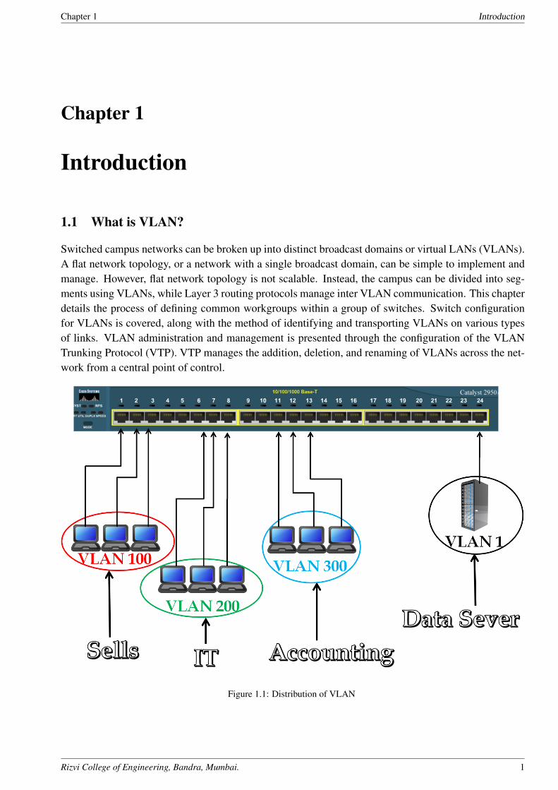
Switched campus networks can be broken up into distinct broadcast domains or virtual LANs (VLANs).A flat network topology, or a network with a single broadcast domain, can be simple to implement andmanage. However, flat network topology is not scalable. Instead, the campus can be divided into seg-ments using VLANs, while Layer 3 routing protocols manage inter VLAN communication. This chapterdetails the process of defining common workgroups within a group of switches. Switch configurationfor VLANs is covered, along with the method of identifying and transporting VLANs on various typesof links. VLAN administration and management is presented through the configuration of the VLANTrunking Protocol (VTP). VTP manages the addition, deletion, and renaming of VLANs across the net-work from a central point of control.
Figure 1.1: Distribution of VLAN
Rizvi College of Engineering, Bandra, Mumbai. 1
Chapter 1 Introduction
1.2 What is trunk?
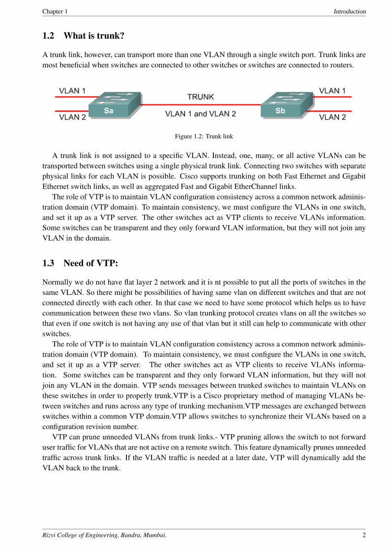
A trunk link, however, can transport more than one VLAN through a single switch port. Trunk links aremost beneficial when switches are connected to other switches or switches are connected to routers.
Figure 1.2: Trunk link
A trunk link is not assigned to a specific VLAN. Instead, one, many, or all active VLANs can betransported between switches using a single physical trunk link. Connecting two switches with separatephysical links for each VLAN is possible. Cisco supports trunking on both Fast Ethernet and GigabitEthernet switch links, as well as aggregated Fast and Gigabit EtherChannel links.
The role of VTP is to maintain VLAN configuration consistency across a common network adminis-tration domain (VTP domain). To maintain consistency, we must configure the VLANs in one switch,and set it up as a VTP server. The other switches act as VTP clients to receive VLANs information.Some switches can be transparent and they only forward VLAN information, but they will not join anyVLAN in the domain.
1.3 Need of VTP:
Normally we do not have flat layer 2 network and it is nt possible to put all the ports of switches in thesame VLAN. So there might be possibilities of having same vlan on different switches and that are notconnected directly with each other. In that case we need to have some protocol which helps us to havecommunication between these two vlans. So vlan trunking protocol creates vlans on all the switches sothat even if one switch is not having any use of that vlan but it still can help to communicate with otherswitches.
The role of VTP is to maintain VLAN configuration consistency across a common network adminis-tration domain (VTP domain). To maintain consistency, we must configure the VLANs in one switch,and set it up as a VTP server. The other switches act as VTP clients to receive VLANs informa-tion. Some switches can be transparent and they only forward VLAN information, but they will notjoin any VLAN in the domain. VTP sends messages between trunked switches to maintain VLANs onthese switches in order to properly trunk.VTP is a Cisco proprietary method of managing VLANs be-tween switches and runs across any type of trunking mechanism.VTP messages are exchanged betweenswitches within a common VTP domain.VTP allows switches to synchronize their VLANs based on aconfiguration revision number.
VTP can prune unneeded VLANs from trunk links.- VTP pruning allows the switch to not forwarduser traffic for VLANs that are not active on a remote switch. This feature dynamically prunes unneededtraffic across trunk links. If the VLAN traffic is needed at a later date, VTP will dynamically add theVLAN back to the trunk.
Rizvi College of Engineering, Bandra, Mumbai. 2
Chapter 2 Trunking Protocol
Chapter 2
Trunking Protocol
Because a trunk link can be used to transport many VLANs, a switch must identify frames withtheirVLANs as they are sent and received over a trunk link. Frame identification, or tagging,assigns a uniqueuser-defined ID to each frame transported on a trunk link. This ID can bethought of as the VLAN num-ber or VLAN color, as if each VLAN was drawn on a networkdiagram in a unique color.VLAN frameidentification was developed for switched networks. As each frame is transmittedover a trunk link, aunique identifier is placed in the frame header. As each switch along the wayreceives these frames, theidentifier is examined to determine to which VLAN the framesbelong.
If frames must be transported out another trunk link, the VLAN identifier is retained inthe frameheader. Otherwise if frames are destined out an access link, the switch removesthe VLAN identifierbefore transmitting the frames to the end station. Therefore, all traces ofVLAN association are hiddenfrom the end station. VLAN identification can be performed using several methods. Each uses a differentframeidentifier mechanism, and some are suited for specific network media. These methods aredescribedin the sections that follow.
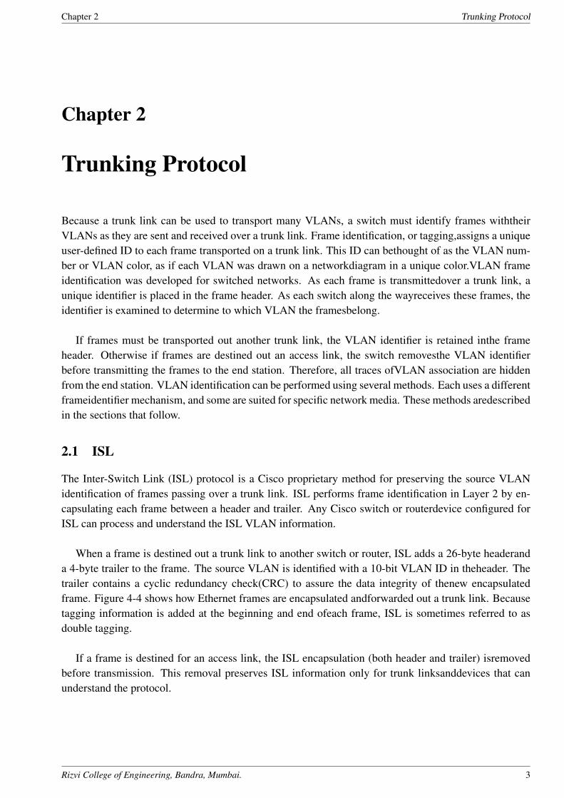
2.1 ISL
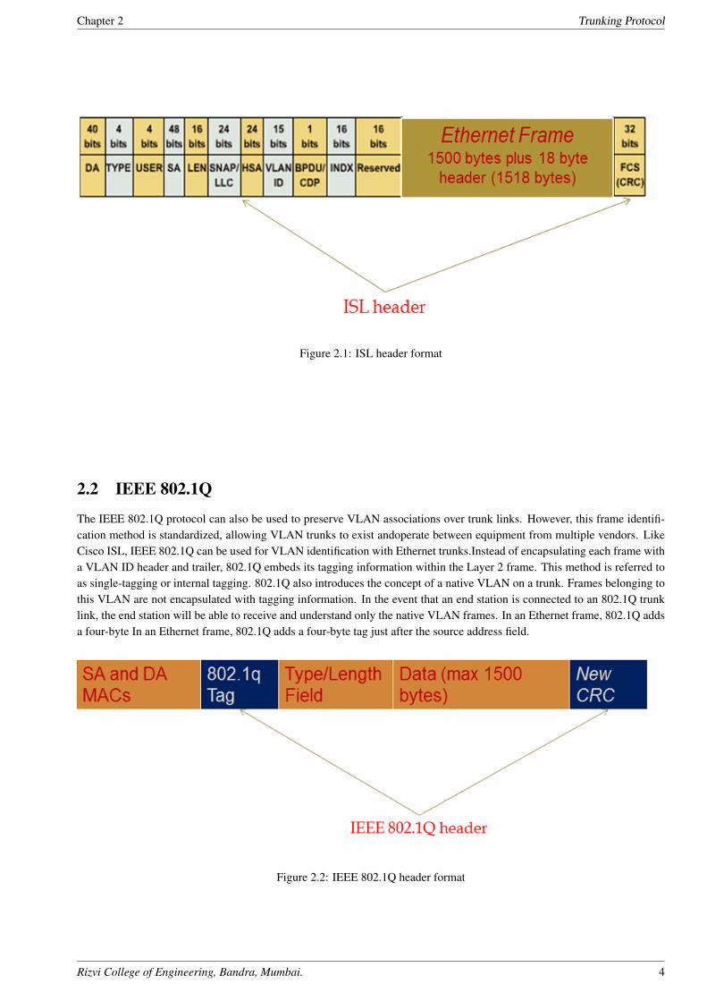
The Inter-Switch Link (ISL) protocol is a Cisco proprietary method for preserving the source VLANidentification of frames passing over a trunk link. ISL performs frame identification in Layer 2 by en-capsulating each frame between a header and trailer. Any Cisco switch or routerdevice configured forISL can process and understand the ISL VLAN information.
When a frame is destined out a trunk link to another switch or router, ISL adds a 26-byte headeranda 4-byte trailer to the frame. The source VLAN is identified with a 10-bit VLAN ID in theheader. Thetrailer contains a cyclic redundancy check(CRC) to assure the data integrity of thenew encapsulatedframe. Figure 4-4 shows how Ethernet frames are encapsulated andforwarded out a trunk link. Becausetagging information is added at the beginning and end ofeach frame, ISL is sometimes referred to asdouble tagging.
If a frame is destined for an access link, the ISL encapsulation (both header and trailer) isremovedbefore transmission. This removal preserves ISL information only for trunk linksanddevices that canunderstand the protocol.
Rizvi College of Engineering, Bandra, Mumbai. 3
Chapter 2 Trunking Protocol
Figure 2.1: ISL header format
2.2 IEEE 802.1Q
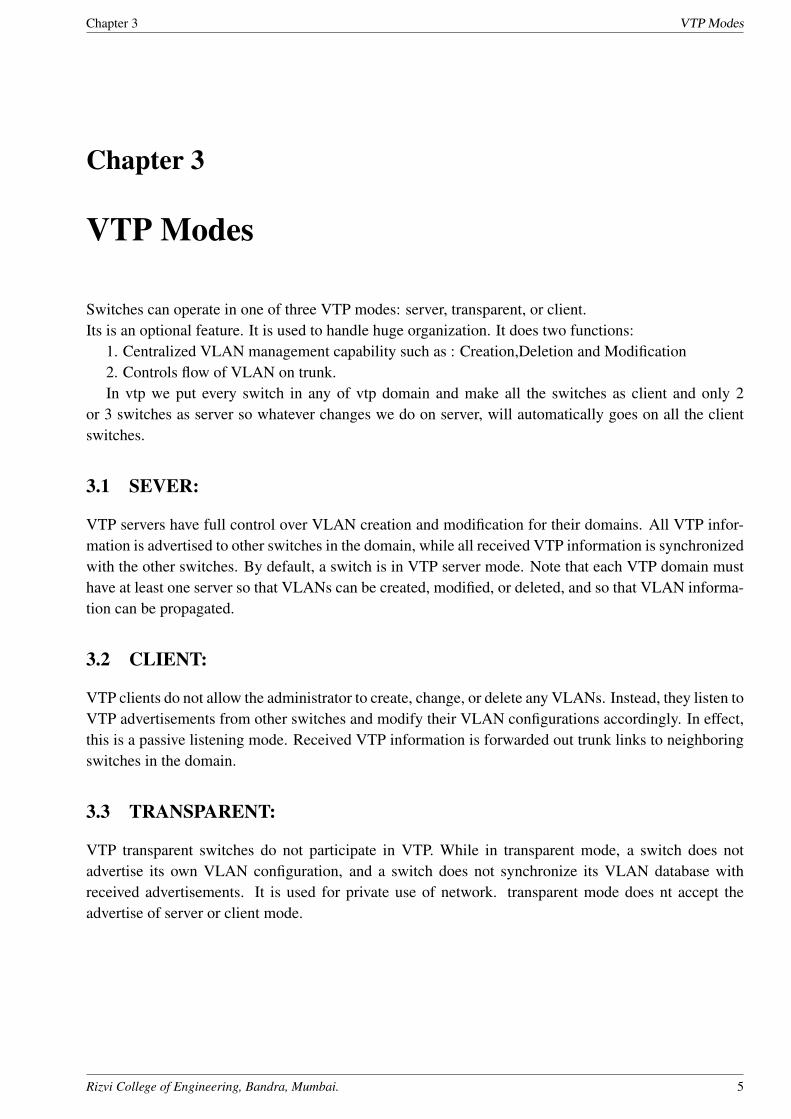
The IEEE 802.1Q protocol can also be used to preserve VLAN associations over trunk links. However, this frame identifi-cation method is standardized, allowing VLAN trunks to exist andoperate between equipment from multiple vendors. LikeCisco ISL, IEEE 802.1Q can be used for VLAN identification with Ethernet trunks.Instead of encapsulating each frame witha VLAN ID header and trailer, 802.1Q embeds its tagging information within the Layer 2 frame. This method is referred toas single-tagging or internal tagging. 802.1Q also introduces the concept of a native VLAN on a trunk. Frames belonging tothis VLAN are not encapsulated with tagging information. In the event that an end station is connected to an 802.1Q trunklink, the end station will be able to receive and understand only the native VLAN frames. In an Ethernet frame, 802.1Q addsa four-byte In an Ethernet frame, 802.1Q adds a four-byte tag just after the source address field.
Figure 2.2: IEEE 802.1Q header format
Rizvi College of Engineering, Bandra, Mumbai. 4
Chapter 3 VTP Modes
Chapter 3
VTP Modes
Switches can operate in one of three VTP modes: server, transparent, or client.Its is an optional feature. It is used to handle huge organization. It does two functions:
1. Centralized VLAN management capability such as : Creation,Deletion and Modification2. Controls flow of VLAN on trunk.In vtp we put every switch in any of vtp domain and make all the switches as client and only 2
or 3 switches as server so whatever changes we do on server, will automatically goes on all the clientswitches.
3.1 SEVER:
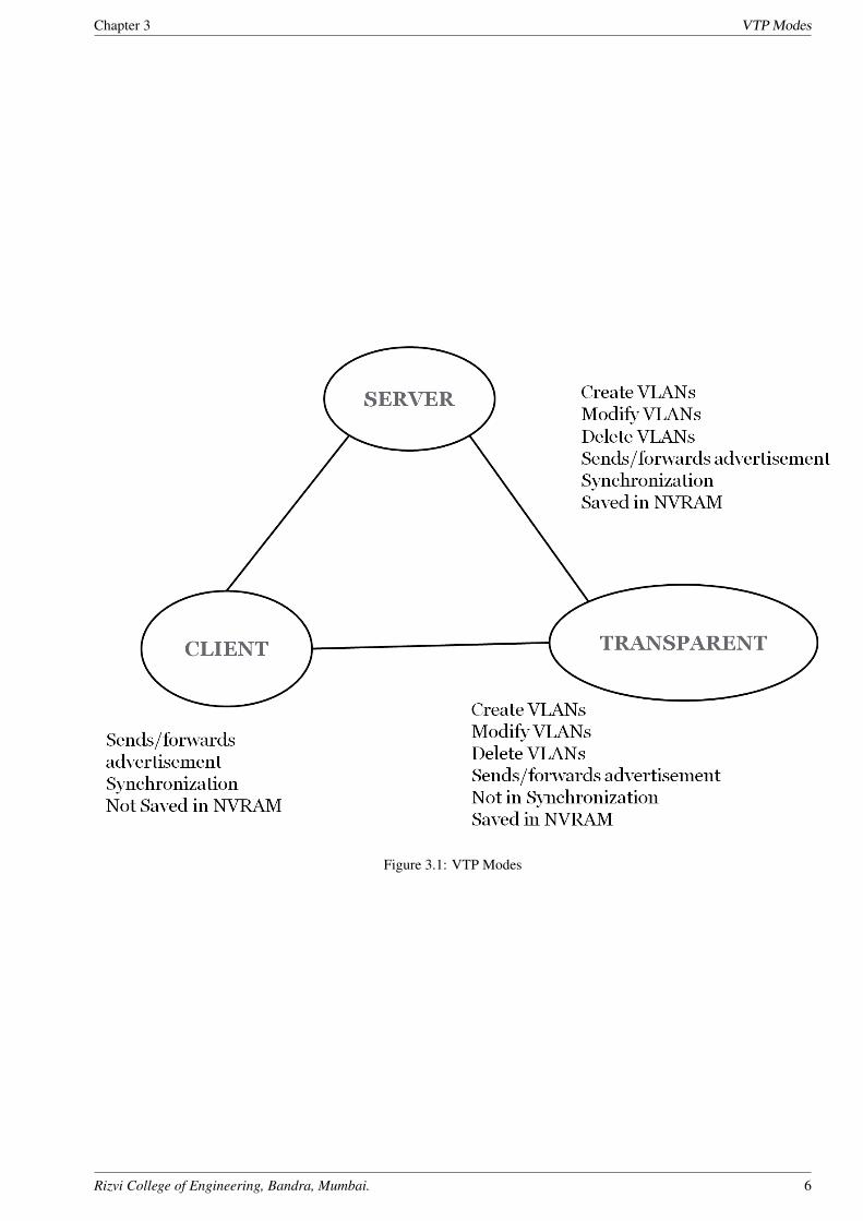
VTP servers have full control over VLAN creation and modification for their domains. All VTP infor-mation is advertised to other switches in the domain, while all received VTP information is synchronizedwith the other switches. By default, a switch is in VTP server mode. Note that each VTP domain musthave at least one server so that VLANs can be created, modified, or deleted, and so that VLAN informa-tion can be propagated.
3.2 CLIENT:
VTP clients do not allow the administrator to create, change, or delete any VLANs. Instead, they listen toVTP advertisements from other switches and modify their VLAN configurations accordingly. In effect,this is a passive listening mode. Received VTP information is forwarded out trunk links to neighboringswitches in the domain.
3.3 TRANSPARENT:
VTP transparent switches do not participate in VTP. While in transparent mode, a switch does notadvertise its own VLAN configuration, and a switch does not synchronize its VLAN database withreceived advertisements. It is used for private use of network. transparent mode does nt accept theadvertise of server or client mode.
Rizvi College of Engineering, Bandra, Mumbai. 5
Chapter 3 VTP Modes
Figure 3.1: VTP Modes
Rizvi College of Engineering, Bandra, Mumbai. 6
Chapter 4 VTP Messages
Chapter 4
VTP Messages
Each switch participating in VTP advertises VLANs, revision numbers, and VLAN parameterson itstrunk ports to notify other switches in the management domain. VTP advertisements aresent as multicastframes. The switch intercepts frames sent to the VTP multicast address andprocesses them with itssupervisory processor. VTP frames are forwarded out trunk links as aspecial case. Because all switchesin a management domain learn of new VLAN configuration changes, aVLAN need only be created andconfigured on just one VTP server switch in the domain.
The VTP advertisement process starts with configuration revision number 0 (zero). Whensubsequentchanges are made, the revision number is incremented before advertisements aresent out. When listeningswitches receive an advertisement with a greater revision number thanis locally stored. If advertisementis lower revision number thanis locally stored then switch discards the frame. TheVTP revision numberis stored in NVRAM.
If the VTP revision number is not reset to zero, a new server switch might advertise VLANs asnon-existent or deleted. If the advertised revision number happens to be greater than previous legitimateadvertisements, listening switches would overwrite good VLAN database entrieswith null or deletedVLAN status information. This is referred to as a VTP synchronizationproblem. Advertisements canoriginate as requests from client-mode switches that want to learn aboutthe VTP database at boot-uptime. As well, advertisements can originate fromserver-mode switches as VLAN configuration changesoccur. VTP advertisements can occur in three forms:
4.1 CRN number
CRN number stands for configuration revision number. It is 32-bit number. By default value is 0. Itis incremented each time a VLAN is added or removed and it is reset to 0 is domain name changes.Switch uses it to see if information is more recent that what it already holds i.e.if it gets the updateshaving CRN number which it already holds then it will discard that frame and if it is latest from whichit already holds then it accepts the frame. we can see this number by putting command as ”show vtpstatus”.
4.2 VTP Advertisements
4.2.1 Summary advertisements
VTP domain servers will send summary advertisementsevery 300 seconds and every time a VLANtopology change occurs. The summaryadvertisement lists information about the management domain,including VTP version,domain name, configuration revision number, timestamp, MD5 encryption hashcode, andthe number of subset advertisements to follow. For VLAN configuration changes,summary
Rizvi College of Engineering, Bandra, Mumbai. 7
Chapter 4 VTP Messages
advertisements are followed by one or more subset advertisements, with more specific VLAN configu-ration data.
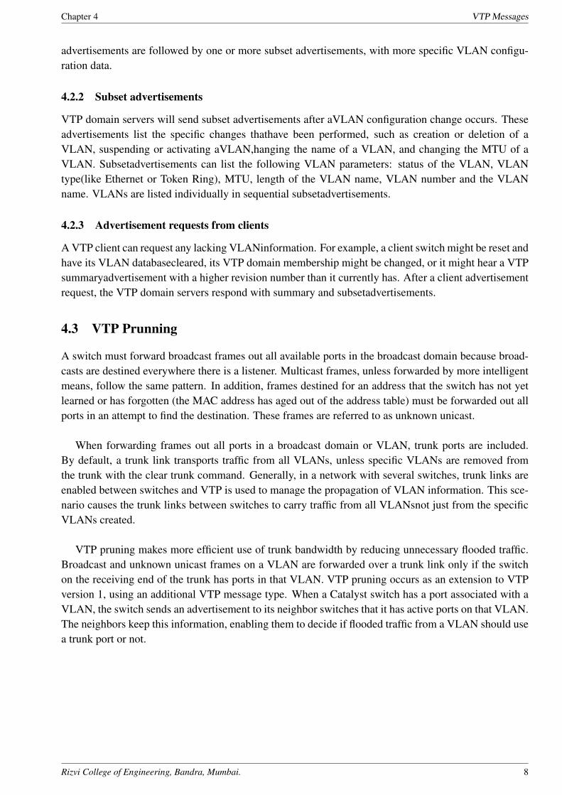
4.2.2 Subset advertisements
VTP domain servers will send subset advertisements after aVLAN configuration change occurs. Theseadvertisements list the specific changes thathave been performed, such as creation or deletion of aVLAN, suspending or activating aVLAN,hanging the name of a VLAN, and changing the MTU of aVLAN. Subsetadvertisements can list the following VLAN parameters: status of the VLAN, VLANtype(like Ethernet or Token Ring), MTU, length of the VLAN name, VLAN number and the VLANname. VLANs are listed individually in sequential subsetadvertisements.
4.2.3 Advertisement requests from clients
A VTP client can request any lacking VLANinformation. For example, a client switch might be reset andhave its VLAN databasecleared, its VTP domain membership might be changed, or it might hear a VTPsummaryadvertisement with a higher revision number than it currently has. After a client advertisementrequest, the VTP domain servers respond with summary and subsetadvertisements.
4.3 VTP Prunning
A switch must forward broadcast frames out all available ports in the broadcast domain because broad-casts are destined everywhere there is a listener. Multicast frames, unless forwarded by more intelligentmeans, follow the same pattern. In addition, frames destined for an address that the switch has not yetlearned or has forgotten (the MAC address has aged out of the address table) must be forwarded out allports in an attempt to find the destination. These frames are referred to as unknown unicast.
When forwarding frames out all ports in a broadcast domain or VLAN, trunk ports are included.By default, a trunk link transports traffic from all VLANs, unless specific VLANs are removed fromthe trunk with the clear trunk command. Generally, in a network with several switches, trunk links areenabled between switches and VTP is used to manage the propagation of VLAN information. This sce-nario causes the trunk links between switches to carry traffic from all VLANsnot just from the specificVLANs created.
VTP pruning makes more efficient use of trunk bandwidth by reducing unnecessary flooded traffic.Broadcast and unknown unicast frames on a VLAN are forwarded over a trunk link only if the switchon the receiving end of the trunk has ports in that VLAN. VTP pruning occurs as an extension to VTPversion 1, using an additional VTP message type. When a Catalyst switch has a port associated with aVLAN, the switch sends an advertisement to its neighbor switches that it has active ports on that VLAN.The neighbors keep this information, enabling them to decide if flooded traffic from a VLAN should usea trunk port or not.
Rizvi College of Engineering, Bandra, Mumbai. 8
Chapter 5 Conclusion and Future Scope
Chapter 5
Conclusion and Future Scope
5.1 Future Scope
VTP version 3 is the third version of the VLAN trunk protocol and enhances its initial functions wellbeyond the handling of VLAN matters.
Much work has gone into improving the usability of VTP version 3 in three major areas:
The new version of VTP offers better administrative control over which device is allowed to updateother devices view of the VLAN topology. The chance of unintended and disruptive changes is sig-nificantly reduced, and availability is increased. The reduced risk of unintended changes will ease thechange process and help speed deployment.
Functionality for the VLAN environment has been significantly expanded. Two enhancements aremost beneficial for todays networks:
In addition to supporting the earlier ISL VLAN range from 1 to 1001, the new version supports thewhole IEEE 802.1Q VLAN range up to 4095.
In addition to supporting the concept of normal VLANs, VTP version 3 can transfer information re-garding Private VLAN (PVLAN) structures.
The third area of major improvement is support for databases other than VLAN (for example, MST).
5.2 Conclusion
It is very good for big organisation, since it allows multiple VLANs on a single link i.e trunk. VLANTrunking Protocol manages big netwrok by creating VTP modes which helps in creating VLANs withoutgoing on all the switches again and again. it gives ease of management,flexibility,security etc. The datais not lost even if device goes down since its server mode saves all the data in flash memory.
Rizvi College of Engineering, Bandra, Mumbai. 9
References
References
[1] Business Computing and Global Informatization (BCGIN), 2012 Second International Conferenceon
[2] Network of the Future (NOF), 2012 Third International Conference on the
[3] Parallel and Distributed Systems, IEEE Transactions on (Volume:22 , Issue: 2 )
[4] http://en.wikipedia.org/wiki
Rizvi College of Engineering, Bandra, Mumbai. 10
Project Hosting
Appendix A
Project Hosting
The report is shared at Academia.edu. The complete report about the seminar is uploaded here for futurereference.
Report Link : http://www.academia.edu/attachments/6516122/download_file
QR CODE:
Rizvi College of Engineering, Bandra, Mumbai. 11


![English in Canada [submitted fall 2014]](https://img.dokumen.tips/doc/110x75/633d53c1062e7fd55b0646a5/english-in-canada-submitted-fall-2014.jpg)


![[Modul Konsep Jaringan] Bab 10 VLAN](https://img.dokumen.tips/doc/110x75/635a7eb278abe3be930daed9/modul-konsep-jaringan-bab-10-vlan.jpg)


