Embed Size (px)
Citation preview
A Semantic Network-Based DesignMethodology for XML Documents
LING FENGUniversity of Twente, The NetherlandsELIZABETH CHANGUniversity of Newcastle, AustraliaandTHARAM DILLONLa Trobe University, Australia
The eXtensible Markup Language (XML) is fast emerging as the dominant standard for describ-ing and interchanging data among various systems and databases on the Internet. It offers theDocument Type Definition (DTD) as a formalism for defining the syntax and structure of XMLdocuments. The XML Schema definition language, as a replacement for the DTD, provides morerich facilities for defining and constraining the content of XML documents. However, it does notconcentrate on the semantics that underlies these documents, representing a logical data modelrather than a conceptual model. To enable efficient business application development in large-scaleelectronic commerce environments, it is necessary to describe and model real-world data semanticsand their complex interrelationships. In this article, we describe a design methodology for XMLdocuments. The aim is to enforce XML conceptual modeling power and bridge the gap betweensoftware development and XML document structures. The proposed methodology is comprised oftwo design levels: the semantic level and the schema level. The first level is based on a semanticnetwork, which provides semantic modeling of XML through four major components: a set of atomicand complex nodes, representing real-world objects; a set of directed edges, representing semanticrelationships between the objects; a set of labels denoting different types of semantic relationships,including aggregation, generalization, association, and of-property relationships; and finally a set ofconstraints defined over nodes and edges to constrain semantic relationships and object domains.The other level of the proposed methodology is concerned with detailed XML schema design, in-cluding element/attribute declarations and simple/complex type definitions. The mapping betweenthe two design levels is proposed to transform the XML semantic model into the XML Schema,based on which XML documents can be systematically created, managed, and validated.
Categories and Subject Descriptors: H.2.1 [Information Systems]: Database Management—logical design
General Terms: Design, Languages
This work was completed while L. Feng was at Infolab, Tilburg University in the Netherlands.Author’s addresses: L. Feng, Dept. of Computer Science, University of Twente, The Netherlands;email: [email protected]; E. Chang, Department of Computer Science & Software Engineering,University of Newcastle, Australia; email: [email protected]; T. Dillon, Department ofComputer Science & Computer Engineering, La Trobe University, Australia; email: [email protected] to make digital/hard copy of part or all of this work for personal or classroom use isgranted without fee provided that the copies are not made or distributed for profit or commercialadvantage, the copyright notice, the title of the publication, and its date appear, and notice is giventhat copying is by permission of the ACM, Inc. To copy otherwise, to republish, to post on servers,or to redistribute to lists, requires prior specific permission and/or a fee.C© 2002 ACM 1046-8188/02/1000-0390 $5.00
ACM Transactions on Information Systems, Vol. 20, No. 4, October 2002, Pages 390–421.
Semantic Network-Based Design Methodology • 391
Additional Key Words and Phrases: XML, design methodology, conceptual modeling, semanticnetwork, XML Schema
1. INTRODUCTION
XML was introduced in 1996 to overcome the deficiencies of HTML. It is muchmore powerful than HTML, allowing structural and semantic markups, allow-ing presentation of specific instructions using style sheets, and allowing the in-corporation of metainformation and somewhat more flexible link managementthan HTML. It builds on the principles and conventions of the Standard Gen-eralized Markup Language (SGML) [Bryan 1992], and provides a simple yetpowerful mechanism for information storage, processing, and delivery. Nowa-days, XML has become an increasingly important data format for storing andinterchanging data among various systems and databases on the Internet. Asa new markup language that supports user-defined tags, and encourages theseparation of document content from its presentation, XML is able to auto-mate Web information processing, in particular for data exchange and intero-perability which are major issues in business-to-business electronic commerce[Consortium 2000a,d]. In data exchange applications, whenever composite datamust be exchanged between two programs, XML serves as a suitable formatfor making the data self-describing. XML is thus, in part, a data representa-tion language that lets us describe data and create vocabularies to exchangeinformation. In addition, XML separates data from presentation, making themreusable. The Document Type Definition (DTD) offered by XML can be usedas a formalism for defining the syntax and structure of XML documents. TheXML Schema definition language, as a replacement for the DTD, provides morerich facilities for defining and constraining the content of XML documents[Sahuguet 2000].
However, in Web applications, writing XML is a lot more work than writingHTML because XML requires more knowledge about the relationships betweenelements rather than the content itself. On the other hand, to enable efficientbusiness application development in large-scale electronic commerce environ-ments, current XML lacks the modeling power in describing real-world dataand their complex interrelationships, and thus providing the objects’ necessarysemantics.
These factors highlight the need for a design methodology to provide a foun-dation for the design and development of XML documents.
As XML bears a close similarity to semistructured data models [Bradley1998; Buneman et al. 2001; Beeri and Tzaban 1999], one current trend in the lit-erature is to apply data models developed for semistructured and unstructureddata to XML [Goldman et al. 1999]. The Object Exchange Model (OEM) devel-oped at Stanford University is a simple, self-describing, nested object modelthat represents semistructured data by a labeled directed graph [Goldman andWidom 1997; Buneman et al. 1996]. The OEM model was further migratedto work with XML [Goldman et al. 1999], where OEM’s object corresponds toelement, and OEM’s subobject relationship mirrors element nesting in XML.
ACM Transactions on Information Systems, Vol. 20, No. 4, October 2002.

392 • L. Feng et al.
When we compare the OEM-based XML data model with the one describedin this article, although both adopt graphic notations, there is a fundamentaldifference. The former models XML documents at the instance level. It doesnot give an instance-independent description of the data. In contrast, we modelXML data at the concept level through a set of semantic relationships in-cluding aggregation, generalization, association, and of-property, and variousconstraints defined on objects and their relationships.
W3C provides an XML Data Model to visualize the structures of XML doc-uments [Consortium 2000c]. This model provides no more than a baseline onwhich more complex models can be built. It presents an XML document as alinearization of a tree structure. This model focuses more on the syntacticstructure of XML documents; it does not address semantic modeling issuesfor XML documents.
The Resource Description Framework (RDF) is part of the result of the W3CMetadata Activity. The aim of RDF is to provide a robust and flexible way tostandardize the definition and use of metadata, descriptions of Web-based re-sources [Consortium 2000b]. RDF emphasizes facilities to enable automatedprocessing of Web resources. It is a foundation for processing metadata soas to provide interoperability between applications that exchange machine-understandable information on the Web. The broad goal of RDF is to define amechanism for describing resources that makes no assumptions about a par-ticular application domain, nor predefines the semantics of any applicationdomain. In general, RDF is a model of metadata. It uses XML to specify meta-data semantics. In this sense, RDF and XML are complementary. Since RDFaims to provide a common, generic, and domain-neutral information descrip-tion framework, its modeling primitives are not as rich as a semantic network,which captures more semantics such as different kinds of interrelationshipsamong real-world entities, together with different constraints enforced overthese interrelationships. Also, as XML currently gains increasing importancein data exchange and dissemination on the Internet, for a specific application, itwould be important and useful to build up its semantic model, and then convertit into XML Schema.
Recently, Conrad et al. [2000] proposed conceptually modeling XML DTDsand thus classes of documents on the basis of the Unified Modeling Lan-guage (UML). The idea was to use essential parts of static UML to modelXML data schemata. The mapping between the static part of UML specifi-cation (i.e., class diagrams) and XML DTDs was developed. To take advan-tage of all facets that DTD concepts offer, the authors extended the UMLlanguage in a UML-compliant way. An object-oriented method was furtherpresented in Xiao et al. [2001b,a] to conceptually model XML Schema. Ourwork is distinguished from the above ones in the following aspects. First,we focus on the design methodology for XML documents, which is comprisedof two design levels, that is, the semantic level and the schema level. Sec-ond, our transformations from the semantic level to the schema level tar-get the most general semantic relationships between objects, and are thusnot limited to UML. In particular, we take different perspectives regardingthese semantic relationships (e.g., strong/weak adhesion, ordered composition,
ACM Transactions on Information Systems, Vol. 20, No. 4, October 2002.
Semantic Network-Based Design Methodology • 393
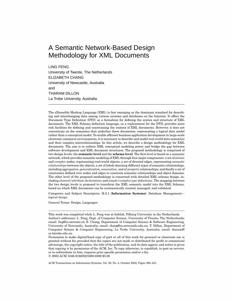
Fig. 1. A two-level design approach.
homogeneity/heterogeneity and exclusion in aggregation relationships, inher-itance, and overriding in generalization relationships, and strong/weak adhe-sion and exclusion in association relationships), and various constraints onobjects into consideration, and examine how they can be realized in the XMLSchema.
Our current article highlights an XML design methodology based on a se-mantic network. The aim is to enforce XML conceptual modeling power, makingit easier to create, manage, retrieve, and validate the semantics of the XMLschema. The proposed methodology is based on two design levels: a semanticlevel and a schema level, as shown in Figure 1. We first present a way tosemantically model XML using a semantic network. It has four major compo-nents: a set of atomic and complex nodes, representing real-world objects; a setof directed edges, representing semantic relationships between the objects; a setof labels denoting different types of semantic relationships, including aggrega-tion, generalization, association, and of-property relationships; and finally, a setof constraints defined over nodes and edges to constrain semantic relationshipsand object domains. We then examine the mapping from the XML semanticlevel to the corresponding XML schema level, which is mainly concerned withdetailed XML element/attribute declarations and simple/complex type defini-tions. Based on the generated XML Schema, XML instance documents can thenbe systematically constructed and controlled.
With the proposed methodology, it is possible to combine software develop-ment with the XML data schemata. This will enable one to improve reuse atboth document and application design levels, and support the generation ofcommon application components.
The remainder of the article is organized as follows. Section 2 presents asemantic network model for XML. Section 3 describes the mapping processfrom the XML semantic level to the XML schema level. Section 4 concludes thearticle with a brief discussion of future work.
2. XML SEMANTIC LEVEL
In this section, we first provide a brief review of XML document structure, andthen describe a semantic data model for XML based on a semantic network.
2.1 XML Document Structure
XML is concerned with describing the structure of documents that are storedin electronic format, in a form that is accessible to both people and computer
ACM Transactions on Information Systems, Vol. 20, No. 4, October 2002.
394 • L. Feng et al.
Fig. 2. A hierarchical document structure example.
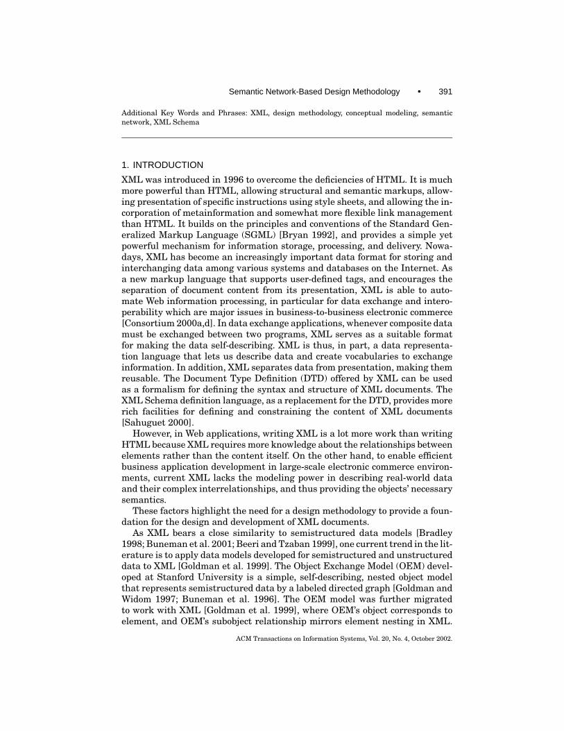
software. An XML format data file contains a mixture of document texts andXML markups, which organize and identify the components of a document.XML markups build on the concept of macro-based typesetting languages.A start-tag and an end-tag, together with the data enclosed by them, com-prise an element. XML elements may contain further embedded elements,leading to a hierarchical document structure. An example of this hierarchyis shown in Figure 2. A Book element may contain a Title element and a Con-tent element. The Content element is comprised of a number of Chapter ele-ments, and each Chapter element contains a number of Paragraph elements.In general, each specified element must be a container element or empty. Con-tainer elements may contain text, child elements, or a mixture of both. Theuse of child elements can be controlled in a Required, Optional, or Repeti-tion way. For example, every book must have a title, so the Book elementmust have a Title child element. This is an example of Required. A child el-ement may be an option. This is called Optional. A child element may be re-peatable like the Chapter element and Paragraph element. Each element canbe associated with one or more attributes. An attribute, consisting of an at-tribute name and an attribute value, provides refined information about anelement.
An XML document is usually associated with a type specification called Docu-ment Type Definition containing user-defined element types and attribute spec-ifications that allow one to describe the meaning of the content. In the earlystages of XML development, there were several proposals to introduce XMLSchema. The XML Schema offers a replacement of XML DTD, with the purposeof constraining and documenting the meaning, usage, and relationships of theirconstituent parts such as permissible data types, elements, and their contents,attributes, and attribute values [Consortium 2001]. The schema definition lan-guage, which is itself represented in XML, considerably extends the capabilitiesof XML DTD for defining and constraining the content of XML documents. AnXML Schema is usually comprised of a set of schema components, such as typedefinitions and element declarations. They can be used to assess the validity ofwell-formed element information items. There are 12 kinds of schema compo-nents in total, falling into three groups. The most used components include sim-ple type definitions, complex type definitions, attribute declarations, and elementdeclarations.
ACM Transactions on Information Systems, Vol. 20, No. 4, October 2002.

Semantic Network-Based Design Methodology • 395
2.2 Coupling Semantic Networks with Hierarchical Structures
As models can help users understand the system by abstracting away some ofthe details, the choice of what to model has an enormous effect on the under-standing of the problem and the shape of the solution [Booch et al. 1998]. Herewe utilize a semantic network to convey the semantics carried by the XML hi-erarchical data structures. At first glance, XML and semantic networks seemto be two different things, since XML is frequently used to represent highlyhierarchical information and the latter are intended for the representation ofthe relationships between different objects. Hierarchical data structures areexcellent for organizing data because they have an unambiguous point of view,making their semantics very powerful. Semantic nets, on the other hand, areuseful because they allow us to establish and express many different data struc-tures and relationships explicitly from the same data. Because each of them isimportant, transforming a semantic network into a hierarchical structure willlet us create XML documents from a semantic network model automatically.We also want to do the reverse, which will let us import XML documents into adatabase that is based on a semantic data model. By understanding the corre-spondence between the semantic data model and XML, developers can begin towork with XML in a similar fashion to the way they work with semantic datamodels. Parsers and programs can be written to transparently move data backand forth between semantic data models and XML documents without losingor altering the semantics associated with the data. In this article, we focus onthe transformation from the semantic network model into XML Schema (asdepicted in Figure 1) in order to help users conveniently generate XML docu-ments by concentrating on the content of the documents and the relationshipsinside them.
2.3 A Semantic Network Model
A semantic network is an oriented diagram consisting of a series of nodes thatare connected to each other through directed labeled edges. In addition, con-straints can be defined over these nodes and edges. At an abstract level, asemantic network model consists of the four components:
— A set of nodes Node, representing real-world objects;— A set of directed edges Edge, representing semantic relationships between the
objects;— A set of labels Label, denoting different types of semantic relationships; and— A set of constraints, Constraint, defined over the nodes and edges.
2.3.1 Nodes. We categorize nodes into basic nodes and complex nodes. Ba-sic nodes have no edges emanating from them. They are the leaf nodes in thesemantic network diagram. Complex nodes are the internal nodes in the net-work diagram. Each complex node has one or more labeled directed edges em-anating from it, each associated with a label, and each going to another node.Figure 3 gives a running example of a semantic network used in the article,where complex nodes are denoted using a box and basic nodes are denoted
ACM Transactions on Information Systems, Vol. 20, No. 4, October 2002.

396 • L. Feng et al.
Fig. 3. A semantic network example.
using a dot. Some complex nodes are like ORDER, PERSON, ITEMS, andBOOK, and so on, each of which has one or more outgoing edges. Basic nodesinclude FirstName, Addresses, Isbn, and so on.
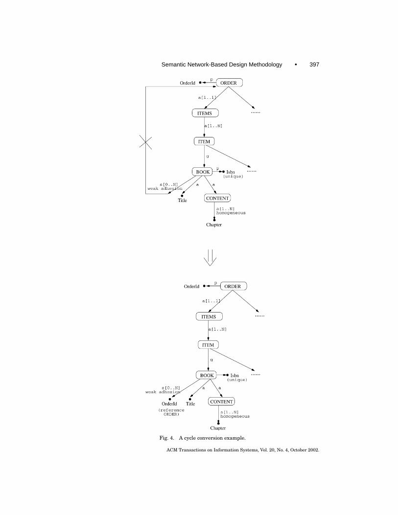
Cycles. An important issue worth mentioning here is that a semantic net-work may have cycles. For instance, a BOOK, appearing in one ORDER, may beassociated with some other ORDERs; that is, a book may be ordered by severalcustomers. To facilitate the transformation from semantic networks to XMLSchema which is addressed in the following section, we propose to break thecycles, and turn a cyclic directed graph (i.e., an original semantic network) intoan equivalent acyclic directed graph without loss of semantics. Suppose we havea cycle (n1, n2, n3, . . . , nm), where node n1 points to node n2, n2 points to n3, andso on, and nm points back to n1 again. To avoid such cyclic references, we allowa new leaf (basic) node nx to be named. It serves as the alias or representativeof node n1, so that node nm can point to nx instead of n1. To ensure equiva-lent transformation, we apply the referential integrity constraint on the newlyintroduced leaf node nx , the key of which refers to node n1. Figure 4 showshow a cycle in Figure 3 is broken and presented in an acyclic manner. Hereanother question arises from such a transformation: where to break a cycle? Inother words, how to identify the root node with which a cycle starts. Concreteapplications play an important role in this situation. If the main theme of theapplication is about ni, say, ORDER in our example, then we put ORDER as theroot node, whose existence precedes other nodes in terms of the application.In contrast, if the application centers around books, then the BOOK node canbe treated as the root. Normally, a link connecting two nodes of the generaliza-tion relationship is not a suitable candidate to break up, since the two nodestogether convey integral information.
Each basic node in the semantic network has a simple content, containingvalues comprised from the domains of basic data types (e.g., string, integer, etc.).
ACM Transactions on Information Systems, Vol. 20, No. 4, October 2002.
Semantic Network-Based Design Methodology • 397
Fig. 4. A cycle conversion example.
ACM Transactions on Information Systems, Vol. 20, No. 4, October 2002.
398 • L. Feng et al.
Let D1, . . . ,Dn be a series of basic data types, whose domains are denoteddom(D1), . . . , dom(Dn). Let DOM=∪n
i=1 dom (Di).
Definition 2.1. A simple content of a basic node can be
1. an atomic value sc ∈ DOM; or2. a constructional value sc, where
— sc = {sc1, sc2, . . . , sck}, called a set value, where ∃i(1≤ i≤n) (sc1, . . . , sck ∈dom(Di)) ∧ ∀i ∀ j (1≤ i, j ≤ k) (i 6= j ⇔ sci 6= sc j ); or
— sc = (sc1, sc2, . . . , sck), called a bag value, where ∃i(1≤ i≤n) (sc1, . . . , sck ∈dom(Di)); or
— sc=<sc1, sc2, . . . , sck>, called a list value, where ∃i(1≤ i≤n) (sc1, . . . ,sck ∈ dom(Di)), and all elements in sc are in a prescribed order, that is, forany two list values sc=<sc1, sc2, . . . , sck > and sc′ =<sc′1, sc′2, . . . , sc′k >,(sc= sc′) if and only if ∀ j (1≤ j ≤ k)(sc j = sc′j ); or
— sc= [sc1|sc2| . . . |sck], called a union value, where ∀ j (1≤ j ≤ k) (sc j ∈DOM).
Among the constructional values for basic nodes, a set value is an unorderedcollection that does not allow duplicates. The values that belong to a set areall unique. A bag value is similar to a set value, except that it allows duplicatevalues to exist. Therefore, it is an unordered collection that allows duplication.A list value is an ordered collection that allows duplicates. A union value allowsany member of a collection as the returning value. Except for a union value, allmembers in a constructional value must be of the same basic type.
On the contrary, the content of a complex node, which is called the complexcontent accordingly, refers to some other nodes through directed labeled edges.Each edge connects two nodes, with a label stating the relationship betweenthe two nodes. Before giving the formal definition of complex content, we firstdefine the concepts of connection, connection cluster, and connection cluster setusing the cableset approach presented in Morgado [1986] and Shapiro [1991].
Definition 2.2. A connection of a node n ∈ Node is an ordered pair < l , n′ >,where l is a label in Lable and n′ is a node in Node, representing that node n isconnected to node n′ via relation l .
Definition 2.3. A connection cluster of a node n ∈ Node is an ordered pair< l , ns >, where l is a label in Lable and ns is a set of nodes inNode, representingthat node n is connected to each node in ns via relation l .
Definition 2.4. A connection cluster set of a node n ∈ Node is a set of connec-tion clusters, {< l1, ns1 >, . . . ,< lk , nsk >}, where ∀i ∀ j (1 ≤ i, j ≤ k) (i 6= j ⇔li 6= l j ).
Definition 2.5. A complex content of a complex node is a connection clusterset.
Definition 2.6. A node n ∈ Node is a 4-tuple (nid, nname, ncategory, ncontent),consisting of a unique node identifier nid, a node name nname, a node category
ACM Transactions on Information Systems, Vol. 20, No. 4, October 2002.
Semantic Network-Based Design Methodology • 399
ncategory indicating whether the node n is basic or complex, and a node contentncontent. If ncategory = “basic,” the node has a simple content; otherwise, it has acomplex content.
Let NB and NC be the set of basic nodes and complex nodes, respectively,where NB ∩ NC =∅ and NB ∪ NC =Node.
Example 2.1. In Figure 3, FirstName, MiddleName, and LastName are ba-sic nodes, each of which has a simple content drawn from the atomic String datatype. Addresses is also a basic node whose simple content is a constructional setvalue, indicating each person can have multiple contact addresses. The com-plex node PERSON is connected to a set of nodes {FirstName, MiddleName,LastName, Addresses} through four outgoing edges, each labeled by relation-ship “a” (denoting aggregation). Thus the complex content of node PERSON is{< “a”, {FirstName, MiddleName, LastName, Addresses} >}.
As the complex node ORDER links to nodes {PERSON, ITEMS, DELIVERY,Remark}with relationship “a”, to node INVOICE with relationship “s” (denotingassociation), and to node OrderId with relationship “p” (denoting of-property),the complex content of ORDER is {< “a”, {FirstName, MiddleName, LastName,Addresses} >, < “s”, {INVOICE} >, < “p”, {OrderId} > }.
2.3.2 Edges. Each edge in the model links two nodes, representing theirsemantic relationship. This binary relationship expresses static interobjectconnection, and hence captures the structural aspects of real-world objects.Here, we organize different nodes mentioned above according to four link types,namely, generalization, aggregation, association, and of-property relationships.
— A generalization is a relationship between a general concept and a morespecific concept. It is sometimes called an “is-a” relationship, which is oftenused to show inheritance between objects.
— An association is a structural relationship, specifying that objects of onekind are connected to objects of another. Given an association connectingtwo objects, we can navigate from one to another, and vice versa. A plainassociation between two objects represents a structural relationship betweenpeers, meaning that both are conceptually at the same level, and no one ismore important than the other.
— An aggregation is a composite relationship, in which a composite object(“whole”) consists of some component objects (“parts”). This kind of rela-tionship represents a “part-of” relationship. Aggregation is often treated asa kind of association. But objects in the aggregation relationship are notconceptually at the same level. This feature distinguishes the aggregationrelationship from the general association relationship [Dillon and Tan 1993;Rahayu et al. 1996].
— The of-property relationship specifies the subsidiary attribute of an object.
Here, we use symbols g , s, a, p to denote generalization, association,aggregation, and of-property relationship, respectively. Thus,Label={g , s, a, p}.
ACM Transactions on Information Systems, Vol. 20, No. 4, October 2002.
400 • L. Feng et al.
Definition 2.7. An edge e ∈ Edge is a triple (elabel, esource node, etarget node), con-sisting of a label elabel ∈ Label stating the link type, the source node of the edgeesource node ∈ Node, and the target node of the edge etarget node ∈ Node. An edge ecan also be pictorially denoted as “esource node
elabel−→ etarget node.”
Example 2.2. In Figure 3, the edge “BOOKp−→ Isbn” specifies that BOOK
node has a property Isbn.1 The edge “PERSONa−→ FirstName” indicates that
PERSON is a “whole” object, and one of its “part” objects is FirstName. “ITEMg−→ BOOK ” represents that the ITEM node is more general than the BOOK
node. The fact that each ORDER may have one or more associated INVOICEsis expressed through the edge “ORDER
s−→ INVOICE.”
Definition 2.8. A well-formed edge “esource nodeelabel−→ etarget node” is an edge
that satisfies the following syntactic conditions.[Condition 1] If the link type is of-property, the source is a complex node and
the target is a basic node. That is, (elabel = p) implies (esource node ∈ NC) and(etarget node ∈ NB);
[Condition 2] If the link type is generalization or aggregation or association,the source is a complex node. That is, (elabel ∈ {g , a, s}) implies (esource node ∈ NC)and (etarget node ∈ Node).
In the article, all the edges under discussion are assumed to be well-formed.Based on the notions of nodes and edges, we further introduce the concepts ofpath, original path, and node depth as follows.
Definition 2.9. A path from node n1 to node nk is a sequence n1, n2, . . . , nk ,where n1, n2, . . . , nk ∈ Node, and for any two consecutive nodes, ni and ni+1(1 ≤ i ≤ k − 1), there exists an edge ei(l , ni, ni+1) ∈ Edge. The path can also bepictorially denoted as “γ ↪→ (n1, n2, . . . , nk).”
We call n1 and nk the starting node and ending node of the path, respectively.The path is said to go through node ni (1 ≤ i ≤ k). The length of a path isthe total number of nodes that the path goes through; that is, k for the path“γ ↪→ (n1, n2, . . . , nk),” denoted as length(γ ) = k.
Definition 2.10. A path from node n1 to node nk , γ ↪→ (n1, n2, . . . , nk), is anoriginal path, if and only if the starting node n1 has no incoming edges.
Note that as no cycles exist in the semantic network after the transformation,as described in Section 3.3.1, for any path, we can find a starting node and alsoan ending node.
Example 2.3. “γ ↪→ (ORDER, PERSON, FirstName)” is a path and also anoriginal path. The length of the path is 3. The path “γ ↪→ (ITEM, BOOK,CONTENT, Chapter)” is not original, since its starting node ITEM has anincoming edge.
With the notion of original path, we can define the depth of a node as follows.
1For simplicity, here, we refer to a specific node using the node name.
ACM Transactions on Information Systems, Vol. 20, No. 4, October 2002.
Semantic Network-Based Design Methodology • 401
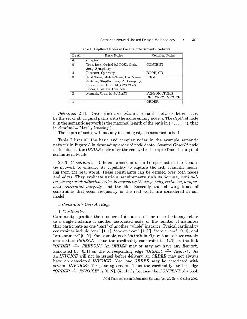
Table I. Depths of Nodes in the Example Semantic Network
Depth Basic Nodes Complex Nodes
6 Chapter5 Title, Isbn, OrderId(BOOK), Code, CONTENT
Song, Symphony4 Discount, Quantity BOOK, CD3 FirstName, MiddleName, LastName, ITEM
Address, ShipCompany, AirCompany,DeliverDate, OrderId (INVOICE),Prices, DueDate, InvoiceId
2 Remark, OrderId (ORDER) PERSON, ITEMS,DELIVERY, INVOICE
1 ORDER
Definition 2.11. Given a node n ∈ Node in a semantic network, let γ1, . . . , γsbe the set of all original paths with the same ending node n. The depth of noden in the semantic network is the maximal length of the path in {γ1, . . . , γs}; thatis, depth(n) =Maxs
i=1 length(γi).The depth of nodes without any incoming edge is assumed to be 1.
Table I lists all the basic and complex nodes in the example semanticnetwork in Figure 3 in descending order of node depth. Assume OrderId nodeis the alias of the ORDER node after the removal of the cycle from the originalsemantic network.
2.3.3 Constraints. Different constraints can be specified in the seman-tic network to enhance its capability to capture the rich semantic mean-ing from the real world. These constraints can be defined over both nodesand edges. They explicate various requirements such as domain, cardinal-ity, strong/weak adhesion, order, homogeneity/heterogeneity, exclusion, unique-ness, referential integrity, and the like. Basically, the following kinds ofconstraints that occur frequently in the real world are considered in ourmodel.
I. Constraints Over An Edge
1. CardinalityCardinality specifies the number of instances of one node that may relateto a single instance of another associated node; or the number of instancesthat participate as one “part” of another “whole” instance. Typical cardinalityconstraints include “one” [1..1], “one-or-more” [1..N], “zero-or-one” [0..1], and“zero-or-more” [0..N]. For example, each ORDER in Figure 3 must have exactlyone contact PERSON. Thus the cardinality constraint is [1..1] on the link“ORDER
a−→ PERSON.” An ORDER may or may not have any Remark,annotated by [0..1] on the corresponding edge “ORDER
a−→ Remark.” Asan INVOICE will not be issued before delivery, an ORDER may not alwayshave an associated INVOICE. Also, one ORDER may be associated withseveral INVOICEs (for pending orders). Thus the cardinality for the edge“ORDER
s−→ INVOICE” is [0..N]. Similarly, because the CONTENT of a book
ACM Transactions on Information Systems, Vol. 20, No. 4, October 2002.

402 • L. Feng et al.
can contain more than one Chapter, the cardinality of the relationship betweenCONTENT and Chapter is [1..N].
The default cardinality specification in Figure 3 is [1..1].The cardinality constraint applies to a connection of the aggregation/
association type.
2. Homogeneous/Heterogeneous CompositionFor an aggregation relationship, when a “whole” object is only made up of “part”objects of the same type, we call it homogeneous composition. For example, theCONTENT of a book comprises several Chapters only. The opposite of homo-geneous composition is heterogeneous aggregation; for example, the PERSONnode is made up of FirstName, MiddleName, LastName, and Addresses.
The homogeneous composition constraint applies to a connection of the ag-gregation type only.
3. AdhesionAdhesion indicates when one peer appears in a relationship, whether anotherpeer must coexist and adhere to it. If the answer is yes, we call it a strong adhe-sion; otherwise, a weak adhesion. For an of-property relationship, such a con-straint implies an optional or compulsory property regarding a certain instance.For example, DeliverDate in Figure 3 will not exist along with DELIVERY beforethe ordered items are sent to the contact person. Therefore, their relationshiphas a weak adhesion. PERSON and LastName have a strong adhesion sinceeach person must have a last name attached. In contrast, the adhesion betweenORDER and INVOICE is weak, as no invoice may be issued once an order iscreated. Note that for an aggregation or association relationship, the adhesionconstraint can be reflected from a cardinality constraint (i.e., [1..1], [1..N], [0..1],[0..N]), whose [0..1] gives a hint for a weak adhesion and [1..1] for a strong adhe-sion. However, compared with a cardinality constraint, the adhesion constraintis more specific and can be applied to an of-property relationship.
Unless explicitly notifying, the aggregation/association/of-property relation-ships in Figure 3 are assumed to have a strong adhesion.
The adhesion constraint applies to a connection of the of-property/aggrega-tion/association type.
II. Constraints Over a Set of Edges
1. Ordered CompositionA “whole” object may be composed of different “part” objects in a particularorder. Taking the composite object PERSON as an example, its contact in-formation consists of FirstName, MiddleName, LastName, and Addresses. Wesay all the component objects of PERSON are ordered: FirstName first, thenMiddleName and LastName, with Addresses in the end. To illustrate, we drawa bar across the ordered aggregation link in Figure 3.
The ordered constraint applies to a connection cluster of the aggregation type.
2. Exclusive DisjunctionGiven a connection cluster, each time only one of the connections exclusivelyapplies. In Figure 3, the DELIVERY of ordered items is performed either by a
ACM Transactions on Information Systems, Vol. 20, No. 4, October 2002.

Semantic Network-Based Design Methodology • 403
Table II. Applicable Relationships of Edge-Based Constraints
Relationship ConstraintType Cardinality Homogeneous Adhesion Ordered Exclusive
Composition Composition Disjunction
of-property√
aggregation√ √ √ √ √
association√ √ √
generalization
ShipCompany or by an AirCompany, but not both at the same time. Thus, thetwo edges “DELIVERY
s−→ ShipCompany” and “DELIVERYs−→ AirCompany”
are exclusively disjunctive. Similarly, a CD in our example may consist of a setof either Songs or Symphonies, but not both. we draw an arc across the linksthat are in exclusive “or” relationship in the figure.
The exclusive disjunction constraint applies to a connection cluster of theaggregation/association type.
Table II summarizes the applicable relationships for different types of edge-based constraints.
III. Constraints over a NodeAll the constraints listed below are defined over basic nodes.
1. UniquenessWhen there is a multiple appearance possibility for a node in the context, theuniqueness constraint requires each of these appearances to have a uniquenode content. Taking the Isbn node as an example, since multiple books may beordered each time, the property isbn may also appear several times, but eachmust have a distinct value.
2. Referential IntegritySometimes the content of one node is linked to the content of another node. Thereferential constraint on a node requires that there must exist another corre-sponding referential node; both of the linked nodes must have the same nodecontent for the referential node. For instance, the “part” node OrderId of IN-VOICE corresponds to the property node OrderId of ORDER for the connectionbetween an ORDER and its INVOICEs.
3. Domain ConstraintDomain constraint is very broad. It can
—restrict the legal range of numerical values by giving the maximal/minimalvalues;
—limit the length of string values, or constrain the patterns of string values.For example, a pattern may instruct the number of characters or format ofallowable components that comprise a valid string value; and
—prespecify the number of members or permissible members for a construc-tional content value (e.g., a list value).
As a summary, the following major constraints can be enforced in the seman-tic network model. Some of them can be specified as complementary information
ACM Transactions on Information Systems, Vol. 20, No. 4, October 2002.

404 • L. Feng et al.
of nodes and edges, and some others as n-ary predicates.
—Constraints attached with an edge e ∈ Edge includee: [<cardinality-constraint>] [strong | weak adhesion] [homogeneous |
heterogeneous]<cardinality-constraint> ::= [1..1] | [1..N] | [0..1] | [0..N](where N is a positive integer).
—Constraints attached with a node n ∈ Node includen: {[<domain-constraint>]} [unique] [reference n′]<domain-constraint> ::= [Val v] | [MinVal v] | [MaxVal v] | [Len v] |
[MinLen v] | [MaxLen v] | [Val s] | [Pattern s](where v is a numerical value, s is a string, and n′ ∈ Node).
—Constraints over a set of edges e1, . . . , en ∈ Edge include[order(e1, . . . , en)] | [exclusive(e1, . . . , en)].
3. MAPPING FROM XML SEMANTIC LEVEL TO XML SCHEMA LEVEL
In this section, we describe the mapping from the semantic network consistingof nodes, edges, and constraints to the XML Schema, which is mainly concernedwith element/attribute declarations and simple/complex type definitions. Inprinciple, each basic node in the semantic network can be mapped to eitheran element or an attribute, both of which are of simple type. Each complexnode in the semantic network can be transformed to an element of complextype, whose content may include embedded subelements. Further definitionsof these XML simple/complex types (e.g., hierarchical structure between ele-ment and subelements for complex types) and their associated properties (e.g.,the occurrence number of element/attribute) are dictated by various seman-tic relationships and constraints in the semantic network. Here, we derive anXML simple/complex type, defined using the simpleType/complexType elementin XML Schema, for each basic/complex node depth by depth starting fromthe highest node depth as shown in Table I for the example in Figure 3. In thefollowing, we describe our derivation procedure in detail.
3.1 Declaring XML Simple Types for Basic Nodes
A basic node has a simple content, which can be either an atomic value of acertain basic type, or a constructional value comprised of a collection of valuesof basic types.
3.1.1 Basic Nodes with Atomic Contents. XML Schema provides a rich setof simple types, including integer, float, string, boolean, date, time, and so on,which can correspond to the basic types in the semantic network. For a basicnode with an atomic content value, we can easily map it to a built-in simpletype in XML Schema [Consortium 2001].
To enforce domain constraints defined over basic nodes in the semantic net-work, we can employ the “facets” mechanism for type creation, provided byXML Schema. In other words, we can derive a new simple type by restrictingan existing simple type through various facets, so that the legal values for the
ACM Transactions on Information Systems, Vol. 20, No. 4, October 2002.

Semantic Network-Based Design Methodology • 405
new type constitute a subset of the existing type’s values. For instance, thedomain constraints like “[MinVal v]” and “[MaxVal v],” aiming to restrict therange of legal values, can be implemented by two facets, “minInclusive” and“maxInclusive.” Taking the Discount node in Figure 3 for example, suppose thediscount rate in the company is always required to be less than or equal to 50%;then we can declare a restricted float data type for Discount Type as follows.
<xsd:simpleType name=“Discount Type”><xsd:restriction base= “xsd:float”><xsd:minInclusive value= “0.0”/><xsd:maxInclusive value= “0.5”/>
</xsd:restriction></xsd:simpleType>
Similarly, the constraints like “[Val v]” and “[Val s]” can be expressed usingthe “enumeration” facet, which can restrict the values of simple types to aset of distinct values. By means of “maxLength,” “minLength,” “length” facets,we can indicate the requirements on the length of values, like the constraints“[Len v],” “[MinLen v],” and “[MaxLen v].” We can also constrain the values ofa string using a facet called “pattern” in conjunction with a pattern expressions in “[Pattern s].” A complete list of facets can be found in XML Schema Part 0:Primer [Consortium 2001].
3.1.2 Basic Nodes with Constructional Contents. A constructional contentof a basic node in the semantic network gives a collection of atomic valuesthrough various collection constructors such as list, set, bag, and union.
List. XML Schema has the concept of a list type, which is comprised ofsequences of atomic types. There are three built-in list types in XML Schema,namely, NMTOKENS, IDREFS, and ENTITIES. In addition to using the built-in list types, users can also derive new list types from existing atomic typesusing the “<xsd:list>” mechanism [Consortium 2001]. For example, we candeclare an XML simple type for a list of float values as follows.
<xsd:simpleType name=“ListofFloat Type”><xsd:list itemType= “xsd:float”/>
</xsd:simpleType>
XML Schema allows several facets, including “length,” “minLength,”“maxLength,” and “enumeration,” to be applied to list types, in order to specifythe number of members and/or permissible members in a constrained list value.For instance, the content of basic node Prices is a list containing three float val-ues, which gives net price, tax, and total price in sequence. We can derive an XMLsimple type, Prices Type, from ListofFloat Type for the node Price as follows.
<xsd:simpleType name=“Prices Type”><xsd:restriction base= “ListofFloat Type”><xsd:length value= “3”/>
</xsd:restriction></xsd:simpleType>
ACM Transactions on Information Systems, Vol. 20, No. 4, October 2002.
406 • L. Feng et al.
An element Prices in an XML instance document like <Prices> 100.00 5.00105.00 </Prices> conforms to the above type definition.
Union. A union type provided by XML Schema enables the content of abasic node to draw its type from the union of multiple atomic and list types[Consortium 2001]. For example, the DueDate in Figure 3 can be expressedusing either the exact date or a string such as “3 days, 2 weeks.” In this case,we can create a union type, DueDate Type, which is built from one atomic datetype and one string data type as follows.
<xsd:simpleType name=“DueDate Type”><xsd:union memberTypes=“xsd:date xsd:string”/>
</xsd:simpleType>
Valid instances of element DueDate of type DueDate Type are like:
<DueDate> 2001-07-01 </DueDate><DueDate> 2 weeks </DueDate>
Set and Bag. For constructional content containing a set/bag of values inthe semantic network, the XML Schema provides no corresponding type sup-port at the moment. However, we can denote a set/bag value by multiple oc-currences of the same element in an XML document. For example, assumeeach contact PERSON has offices located at different regions. He or she can bereached through any of the addresses provided. We can declare an addressunitelement with two XML facets (minOccurs=“1” and maxOccurs=“unbounded”),indicating that the addressunit element can appear one or more times in XMLdocuments as shown below.
<xsd:complexType name=“ADDRESS Type”><xsd:element name=“addressunit” type=“xsd:string” minOccurs=“1”
maxOccurs=“unbounded”/></xsd:complexType>
The following XML fragment conforms to the above schema definition.
<addressunit> Warandelaan 2, Netherlands </addressunit><addressunit> Kowloon 18, Hong Kong </addressunit><addressunit> Clementi Rd 2, Singapore </addressunit>
Further discussion of the two facets is given in Section 4.2.2.To differentiate a set value (without duplication) from a bag value (allowing
duplication), we apply a uniqueness constraint (discussed below) to a set-valuedelement.
The uniqueness and referential constraints can be applied to either atomic orconstructional contents of basic nodes, thanks to XML Schema, which has pro-vided the corresponding <unique> and <keyref> mechanisms to make thesepossible in XML documents.
Uniqueness Constraint. To indicate that one particular attribute or ele-ment value is unique, we can use the “unique” element first to “select” a set ofelements, and then to identify the attribute or element “field” relative to each
ACM Transactions on Information Systems, Vol. 20, No. 4, October 2002.
Semantic Network-Based Design Methodology • 407
selected element that has to be unique within the scope of the set of selectedelements [Consortium 2001]. For example, the semantic network in Figure 3requires the Isbn node of BOOK to have a unique content among the set ofordered books. We can thus make the following declaration for it at the XMLSchema level.
<unique name=“Isbn Unique”><selector xpath=“ORDER/ITEMS/BOOK”/><field xpath=“@Isbn”/>
</unique>
The “selector” element’s “xpath” attribute contains an XPath expression OR-DER/ ITEMS/ BOOK, which selects a list of all the BOOK elements in anORDER instance document. (Here the ITEM node following the ITEMS nodecan be omitted during the transformation of the generalization relationshipas described in Section 4.2.4.) Likewise, the “field” element’s “xpath” attributecontains a second XPath expression @Isbn, specifying that the Isbn attributevalues of those elements must be unique. The prefix symbol @ represents anattribute, indicating that Isbn is an attribute of the BOOK element. Note thatthe XPath expression limits the scope of what must be unique. In the same way,we can declare the uniqueness of the addressunit element value as
<unique name=“addressunit Unique”><selector xpath=“ORDER/PERSON/Addresses”/><field xpath=“addressunit”/>
</unique>
XML Schema also allows one to indicate combinations of fields that must beunique.
Referential Constraint. There are specific ways to express referential con-straints in the XML Schema.
1. One is to employ the ID, IDREF, and IDREFS simple types that are usedfor declaring attributes. For instance, we can declare OrderId of ORDER as anID-typed attribute, and let OrderId under INVOICE be another IDREF-typedattribute, whose value refers to an ID-typed attribute (i.e., OrderId of ORDER)value.
<xsd:complexType name=“ORDER Type”><xsd:attribute name=“OrderId” type=“xsd:ID”/>
</xsd:complexType>
<xsd:complexType name=“INVOICE Type”><xsd:attribute name=“OrderId” type=“xsd:IDREF”/>
</xsd:complexType>
Similarly, the OrderId attribute of BOOK can be of IDREFS type. It takesits value from a list of OrderIds under ORDER elements.
2. The shortcoming with the above transformation method is that ID is a typeof attribute, and so it cannot be applied to elements. To overcome this deficiency,
ACM Transactions on Information Systems, Vol. 20, No. 4, October 2002.
408 • L. Feng et al.
XML Schema provides a more flexible and powerful mechanism through “key”and “keyref,” which share the same syntax as “unique.” For instance, we candeclare the constraint that the OrderId listed under INVOICE must have acorresponding referential part, OrderId, in ORDER as follows.
<key name=“ORDER OrderId”><selector xpath=“ORDER”/><field xpath=“@OrderId”/>
</key>
<keyref name=“INVOICE OrderId Ref” refer=“ORDER OrderId”><selector xpath=“INVOICE”/><field xpath=“@OrderId”/>
</keyref>
The above XML Schema fragment says that the OrderId attribute (<fieldxpath=“@OrderId”/>) of element INVOICE (<selector xpath=“INVOICE”/>)must reference the key attribute OrderId of ORDER.
Unlike method (1), method (2) enables one to specify the scope within whichuniqueness applies whereas the scope of an ID is fixed to be the whole document.Moreover, it allows one to create keys and keyref from combinations of anyelement and attribute content whereas ID has no such facility.
3.2 Declaring XML Complex Types for Complex Nodes
As described in Section 2, the content of a complex node in the semantic networkis a set of connection clusters, linking to some other nodes via directed labelededges. At the XML Schema level, each complex node corresponds to a complex-Type, describing logical relationships between element and subelements and/ortheir attributes, so that the placement of elements and attributes in instancedocuments can be controlled and validated. This feature of XML inherited fromSGML acts as a template for XML documents. Here we generate a complextype for each complex node on a connection cluster basis, and then combine allthe declarations obtained for each connection cluster to get an integral complextype declaration.
Assume n is a complex node whose complex content includes a connectioncluster < l , {n1, . . . , nk} >, where n1, . . . , nk ∈ Node and l ∈ {p, a, s, g}. In thefollowing, we discuss how to derive a complexType for node n, when l representsan “of-property,” “aggregation,” “association,” or “generalization” relationship,respectively.
3.2.1 l = p (“of-property” relationship). The of-property relationship at-taches a property to an object. This property node can be easily mapped toa subsidiary attribute of the element in the XML Schema. For example, theInvoiceId node of INVOICE can be translated into an attribute of the complextype INVOICE Type for INVOICE through <xsd:complexType> as follows.
<xsd:complexType name=“INVOICE Type”><xsd:attribute name=“InvoiceId” type=“xsd:string” use=“required”/>
</xsd:complexType>
ACM Transactions on Information Systems, Vol. 20, No. 4, October 2002.
Semantic Network-Based Design Methodology • 409
The statement (use=“required”) indicates the attribute “InvoiceId” must ap-pear together with an INVOICE for strong adhesion. In the situation wherean attribute is optional, we can set (use=“optional”). For example, the prop-erty DeliverDate is an optional attribute of DELIVERY Type, whose existencedepends on whether the delivery action has taken place.
<xsd:complexType name=“DELIVERY Type”><xsd:attribute name=“DeliverDate” type=“xsd:date” use=“optional”/>
</xsd:complexType>
3.2.2 l =a (“aggregation” relationship). The aggregation relationship rep-resents a “part-of” relationship, indicating that a “whole” object consists of“part” objects. This kind of relationship commonly exists in XML documents.XML assumes that data are hierarchically structured. One element may con-tain subelements, which may in turn contain other subelements. Thereforewe can easily map aggregation relationships in the semantic network ontoXML Schema. To illustrate, let us look at the PERSON node in Figure 3.PERSON represents a composite object, consisting of four component objects:FirstName, MiddleName, LastName, and Addresses. We can create a complextype, PERSON Type, for node PERSON, which is comprised of four subelementsas follows.
<xsd:complexType name=“PERSON Type”><xsd:sequence><xsd:element name=“FirstName” type=“xsd:string”/><xsd:element name=“MiddleName” type=“xsd:string”/><xsd:element name=“LastName” type=“xsd:string”/><xsd:element name=“Addresses” type=“ADDRESS Type”/>
</xsd:sequence></xsd:complexType>
Note that all the subelements at this time have been mapped to the cor-responding simple/complex type declarations, since they are at a higher nodedepth than the node being processed, and have thus been processed already.
Ordered Composition Constraint. The statement <xsd:sequence> in XMLSchema as above captures the sequential semantics of the composition, thatis, ordered constraint among a set of embraced subelements: subelementFirstName comes first, followed by MiddleName, and then LastName, withAddresses in the end. Later these subelements in instance documents mustappear in the same sequential order as they are declared here. In contrast to<xsd:sequence>, XML Schema provides another constructor called <xsd:all>,which allows its subelements to appear in any order, and all the subelementsmust appear once or not at all.
Exclusive Disjunction Constraint. When we have a set of subelementsthat are in an exclusive “or” relationship, the XML content constructor<xsd:choice>, instead of <xsd:sequence> and <xsd:all>, can be applied. For
ACM Transactions on Information Systems, Vol. 20, No. 4, October 2002.

410 • L. Feng et al.
example, for the node CD, a complex type CD Type can be created to allowonly one of its children, Song and Symphony, to appear as its subelement in aninstance document.
<xsd:complexType name=“CD Type”><xsd:choice><xsd:element name=“Song” type=“xsd:string”/><xsd:element name=“Symphony” type=“xsd:string”/>
</xsd:choice></xsd:complexType>
Cardinality Constraint. The cardinality constraint in the semantic networkcan be explicated by associating two XML built-in attributes, “minOccurs” and“maxOccurs,” with subelements under the XML complexType. In general, asubelement is required to appear when the value of “minOccurs” is 1 or more.The maximum number of times a subelement may appear is determined bythe value of the “maxOccurs” attribute. This may be a positive integer valueor the term “unbounded” to indicate there is no limitation on the maximumnumber of occurrences. The default value for both the “minOccurs” and the“maxOccurs” attributes is 1. If we specify a value for only the “minOccurs”attribute, it must be less than or equal to the default value of “maxOccurs”; thatis, it is 0 or 1. Similarly, if we specify a value for only the “maxOccurs” attribute,it must be greater than or equal to the default value of “minOccurs,” that is,1 or more. If both attributes are omitted, the subelement must appear exactlyonce [Consortium 2001].
The cardinality [1..1] in the semantic network model corresponds to the de-fault settings of “minOccurs” and “maxOccurs” at the XML Schema level, car-dinality [1..N] corresponds to (minOccurs=“1” and maxOccurs=“unbounded”),cardinality [0..1] corresponds to (minOccurs=“0” and maxOccurs=“1”), and car-dinality [0..N] to (minOccurs=“0” and maxOccurs=“unbounded”).
For instance, by setting minOccurs=“1” and maxOccurs=“unbounded” forSong and Symphony subelements within the CD Type declaration, we can claimthat each CD element is an aggregation of several songs or symphonies.
<xsd:complexType name=“CD Type”><xsd:choice><xsd:element name=“Song” type=“xsd:string” minOccurs=“1”
maxOccurs=“unbounded”/><xsd:element name=“Symphony” type=“xsd:string” minOccurs=“1”
maxOccurs=“unbounded”/></xsd:choice>
</xsd:complexType>
Adhesion Constraint. By assigning appropriate values to “minOccurs” and“maxOccurs” attributes, we can easily enforce the strong/weak adhesion con-straints for XML documents as well. When one element can exist without oneof its subelements, for example, ORDER can have no Remark, we can simply letthe minimal occurrence number of Remark be 0, so that Remark is not always
ACM Transactions on Information Systems, Vol. 20, No. 4, October 2002.
Semantic Network-Based Design Methodology • 411
required to appear as one part of ORDER. In contrast, we can also convey thestrong adhesion meaning by assigning a value more than 0 to “minOccurs.” Forexample,
<xsd:complexType name=“ORDER Type”><xsd:all><xsd:element name=“PERSON” type=“PERSON Type”/><xsd:element name=“ITEMS” type=“ITEMS Type”/><xsd:element name=“DELIVERY” type=“DELIVERY Type”/><xsd:element name=“Remark” type=“xsd:string” minOccurs=“0”
maxOccurs=“1”/></xsd:all>
</xsd:complexType>
Here the subelements PERSON, ITEMS, DELIVERY, and Remark embracedwithin <xsd:all> and </xsd:all> of ORDER Type can appear in any order, andall of them must appear once or not at all.
Homogeneous Composition Constraint. The “minOccurs” and “maxOccurs”attributes can also be used to describe a homogeneous composition. That is,a “whole” object is made up of only one kind of subelement. For example, wecan declare a complex type CONTENT Type for the node CONTENT, which iscomprised of one or several Chapters.
<xsd:complexType name=“CONTENT Type”><xsd:element name=“Chapter” type=“xsd:string” minOccurs=“1”
maxOccurs=“unbounded”/></xsd:complexType>
3.2.3 l = s (“association” relationship). An association is a structural re-lationship which specifies that an object of one kind is associated with objectsof another. For example, an ORDER is associated with an INVOICE, and aDELIVERY is performed by either a ShipCompany or an AirCompany. The as-sociation relationship implied by a connection cluster in the semantic networkcan be mapped to an XML complex type in the following ways.
1. When the associated object node is a basic node, or a node that carriesbrief information of simple structure, such as the basic nodes ShipCompanyand AirCompany, we can directly put them as the subelements of the sourceobject.
<xsd:complexType name=“DELIVERY Type”><xsd:choice><xsd:element name=“ShipCompany” type=“xsd:string”/><xsd:element name=“AirCompany” type=“xsd:string”/>
</xsd:choice></xsd:complexType>
ACM Transactions on Information Systems, Vol. 20, No. 4, October 2002.

412 • L. Feng et al.
This treatment is similar to the transformation of aggregation relation-ships. The cardinality, adhesion, and exclusive disjunction constraints onassociation relationships can also be expressed through the same mech-anisms as those for aggregation relationships, described in the previoussubsection.
2. When the associated object node is a complex node with a rich contentand can thus be viewed as an individual entity, for example, the associatednode INVOICE of ORDER which is again connected with some other “part”nodes OrderId, Prices, and DueDate, we can declare the source and its asso-ciated objects at the same level. That is, there is no hierarchical relationshipbetween the two. In this case, we can make use of either an attribute or asubelement in the source to refer to its associated one. Taking ORDER and itsassociated INVOICE pair, for example, we can declare two individual complextypes, ORDER Type and INVOICE Type, and make them key referable througheither an augmented attribute of IDREFS type or a subelement InvoiceId asfollows.
1. An attribute-based transformation
<xsd:complexType name=“ORDER Type”><xsd:all><xsd:element name=“PERSON” type=“PERSON Type”/><xsd:element name=“ITEMS” type=“ITEMS Type”/><xsd:element name=“DELIVERY” type=“DELIVERY Type”/><xsd:element name=“Remark” type=“xsd:string” minOccurs=“0”
maxOccurs=“1”/></xsd:all><!- - augment attribute InvoiceId to refer to the associated INVOICE - -><xsd:attribute name=“InvoiceId” type=“xsd:IDREFS” use=“optional”/>
</xsd:complexType>
<xsd:complexType name=“INVOICE Type”><xsd:sequence><xsd:element name=“Prices” type=“Prices Type”/><xsd:element name=“DueDate” type=“DueDate Type”/>
</xsd:sequence><!- - attribute InvoiceId as the key - -><xsd:attribute name=“InvoiceId” type=“xsd:ID”/>
</xsd:complexType>
When the cardinality constraint posed on the association relationship is “one”[1..1] or “zero-or-one” [0..1], we can simply declare the type of InvoiceId underORDER as IDREF. However, for associations with “zero-or-more” [0..N] or “one-or-more” [1..N] cardinality constraints, we must pick the IDREFS type in orderto establish multiple reference connections. Also, with the attribute-based asso-ciation transformation, the adhesion and exclusive disjunction constraints canbe enforced through the attribute occurrence constraint, that is, use=“required”or use=“optional.”
ACM Transactions on Information Systems, Vol. 20, No. 4, October 2002.
Semantic Network-Based Design Methodology • 413
2. A subelement-based transformation
<xsd:complexType name=“ORDER Type”><xsd:all><xsd:element name=“PERSON” type=“PERSON Type”/><xsd:element name=“ITEMS” type=“ITEMS Type”/><xsd:element name=“DELIVERY” type=“DELIVERY Type”/><xsd:element name=“Remark” type=“xsd:string” minOccurs=“0”
maxOccurs=“1”/></xsd:all><!- - augment subelement InvoiceId to refer to the associated INVOICE - -><xsd:element name=“InvoiceId” type=“xsd:string” minOccurs=“0”
maxOccurs=“unbounded”/></xsd:complexType>
<xsd:complexType name=“INVOICE Type”><xsd:sequence><xsd:element name=“Prices” type=“Prices Type”/><xsd:element name=“DueDate” type=“DueDate Type”/>
</xsd:sequence><xsd:attribute name=“OrderId” type=“xsd:IDREF”/><!- - attribute InvoiceId as the key - -><xsd:attribute name=“InvoiceId” type=“xsd:ID”/>
</xsd:complexType>
Since ID, IDREF, and IDREFS can only be the types of attributes rather thanelements, to associate the subelement InvoiceId of ORDER with the attributeInvoiceId of INVOICE, we must employ the XML key reference mechanism asfollows.
<keyref name=“INVOICE InvoiceId Ref” refer=“INVOICE InvoiceId”><selector xpath=“ORDER”/><field xpath=“InvoiceId”/>
</keyref>
<key name=“INVOICE invoiceId”><selector xpath=“INVOICE”/><field xpath=“@InvoiceId”/>
</key>
For subelement-based association transformation, the cardinality, adhesion,and exclusive disjunction constraints on association relationships can be ex-pressed through the same mechanisms as those for aggregation relationships,described in the previous subsection.
3.2.4 l = g (“generalization” relationship). Generalization is an importantcharacteristic in the semantic network model that permits the inheritancemechanism to occur. It organizes objects in taxonomies by their similarities anddifferences, thus structuring the description of objects. An ancestor object holdscommon information, whereas the descendants can inherit this information
ACM Transactions on Information Systems, Vol. 20, No. 4, October 2002.

414 • L. Feng et al.
and add specific contents. The inherited information can be reused or overrid-den in the descendant objects. For example, BOOK and CD are more specificcompared to their parent node ITEM, which holds Discount and Quantity com-mon for either a BOOK or a CD. The generalization mechanism in the seman-tic network can be transformed to XML complex type declarations through theflexible and powerful type creation facilities offered by XML Schema. Basically,the following are the ways to construct a type from existing types at the XMLSchema level [Consortium 2001].
1. Deriving Types by Extension. A newly derived complex type contains allthe elements of the original type plus additional elements that are specific inthe new type. For example, we can simplify the declarations of BOOK Type andCD Type by sharing a common complex type ITEM Type.
<xsd:complexType name=“ITEM Type”><xsd:all><xsd:element name=“Discount” type=“Discount Type”/><xsd:element name=“Quantity” type=“xsd:positiveInteger”/>
</xsd:all></xsd:complexType>
<xsd:complexType name=“BOOK Type”><xsd:complexContent><xsd:extension base=“ITEM Type”><xsd:sequence><xsd:element name=“Title” type=“xsd:string”/><xsd:element name=“CONTENT” type=“CONTENT Type”/>
</xsd:sequence><xsd:attribute name=“OrderId” type=“xsd:IDREFS”/>
</xsd:extension></xsd:complexContent>
</xsd:complexType>
<xsd:complexType name=“CD Type”><xsd:complexContent><xsd:extension base=“ITEM Type”><xsd:choice><xsd:element name=“Song” type=“xsd:string” minOccurs=“1”
maxOccurs=“unbounded”/><xsd:element name=“Symphony” type=“xsd:string” minOccurs=“1”
maxOccurs=“unbounded”/></xsd:choice>
</xsd:extension></xsd:complexContent>
</xsd:complexType>
The two complex types BOOK Type and CD Type contain all the elementsof the ITEM Type plus additional elements that are specific to BOOK and CD.The statement <xsd:complexContent> indicates the contents of the two types
ACM Transactions on Information Systems, Vol. 20, No. 4, October 2002.
Semantic Network-Based Design Methodology • 415
are complex, that is, containing subelements. We state that we are extendingthe base type ITEM Type by the value of the “base” on the “extension” elements.
To simplify the hierarchical structure between elements and subelements inXML documents, after declaring a complex type by extension, we can substitutethe elements of the base type with the derived type directly, since the effectivecontent of the latter consists of the content of the former plus its own content.For example, we can declare the following complex type, ITEMS Type, for nodeITEMS based on BOOK Type and CD Type without the intervention of nodeITEM.
<xsd:complexType name=“ITEMS Type”><xsd:sequence><xsd:element name=“BOOK” type=“BOOK Type” minOccurs=“0”
maxOccurs=“unbounded”/><xsd:element name=“CD” type=“CD Type” minOccurs=“0”
maxOccurs=“unbounded”/></xsd:sequence>
</xsd:complexType>
2. Deriving Complex Types by Restriction. In addition to deriving new com-plex types by extending a base type, it is also possible to derive new types byrestricting an existing base type. As described in XML Schema Part 0: Prima[Consortium 2001], restriction of complex types is conceptually the same as re-striction of simple types, except that the restriction of complex types involvesa type’s declaration rather than the acceptable range of a simply typed value.A complex type derived by restriction in the XML Schema is similar to its basetype, except that its declarations are more limited than the corresponding dec-larations in the base type, and the values represented by the new type are asubset of the values represented by the base type. Therefore, the types derivedby restriction must have the same structure and repeat all the components ofthe base type definition.
For example, suppose we want to update our definition of the ITEMS Typeso that each order must contain at least one book on order. The above complextype definition of ITEMS Type allows the “none” book element to appear in anorder. To update the definition, we can define a new type NEWITEMS Type,and indicate that it is derived by restriction from the base type ITEMS Type.NEWITEMS Type provides a new more restrictive value for the minimum num-ber of BOOK element occurrences. This change narrows the allowable numberof child BOOK elements from a minimum of 0 to a minimum of 1.
<xsd:complexType name=“NEWITEMS Type”><xsd:restriction base=“ITEMS Type”><xsd:complexContent><xsd:sequence><xsd:element name=“BOOK” type=“BOOK Type” minOccurs=“1”
maxOccurs=“unbounded”/><xsd:element name=“CD” type=“CD Type” minOccurs=“0”
maxOccurs=“unbounded”/>
ACM Transactions on Information Systems, Vol. 20, No. 4, October 2002.
416 • L. Feng et al.
</xsd:sequence></xsd:complexContent>
</xsd:restriction></xsd:complexType>
Besides the restriction on the element occurrence numbers, it is also possibleto set a default or fixed value when none was previously given.
3. Redefining Types. The redefinition mechanism allows one to redefinean existing simple/complex type that is obtained from an external schema file[Consortium 2001]. Different from the above two mechanisms (1) and (2), theresulting definition has the same type name as the original one to be modified,and becomes the only definition of this type in the corresponding namespace.The redefine element acts very much as does the include element. It bringsin all the declarations and definitions from an external schema. Suppose aPERSON Type, containing three elements FirstName, MiddleName, and Last-Name, has been predefined in an external schema file called “person.xsd.” Itcan be redefined with the following redefinition mechanism.
<!– bring in person constructs –><xsd:redefine schemaLocation=“http://infolab.kub.nl/person.xsd”><!– redefinition of PERSON Type –><xsd:complexType name=“PERSON Type”><xsd:complexContent><xsd:extension base=“PERSON Type”>
<xsd:element name=“Addresses” type=“ADDRESS Type”/></xsd:extension>
</xsd:complexContent></xsd:complexType>
The complex type definition of PERSON Type uses the same extension syn-tax to add an Addresses element to the definition of PERSON Type. Note thatthe base type is also PERSON Type. Now that PERSON Type has been ex-tended and redefined, such an extension applies to all schema components thatmake use of PERSON Type in the corresponding target name space.
At the end of the transformation for each complex node n in the semanticnetwork, the mapping from each of its connection clusters (< l , {n1, . . . , nk} >)to a complex type, as described through this subsection, is finally combined toget an integral complex type for node n. The appendix at the end of the articleillustrates all the simple/complex types generated for the example semanticnetwork in Figure 3.
4. CONCLUSION
XML has become an increasingly important data format for storing structuredand semistructured text intended for dissemination and ultimate publicationin a variety of media. It is a markup language that supports user-defined tagsand encourages the separation of document content from presentation. In thisarticle, we present a coherent way to integrate the semantic network and the
ACM Transactions on Information Systems, Vol. 20, No. 4, October 2002.
Semantic Network-Based Design Methodology • 417
XML Schema for XML documents, making it easy to create, manage, retrieve,and validate the semantics of the XML schema. The proposed XML designmethodology consists of the semantic level and the schema level. The firstlevel is based on a semantic network, which provides semantic modeling ofXML mainly through nodes, edges, and constraints. The second level is con-cerned with detailed schema design, including element/attribute declarationsand simple/complex type definitions. The mapping from the semantic level tothe schema level is proposed. The generated XML schema can then be used inthe creation of XML instance documents. The XML schema can also be utilizedby other techniques for validating XML instance documents.
For future work, a lot of issues deserve investigation. To evaluate the pro-posed XML design methodology, we plan to develop a system that could auto-mate the transformation from a semantic network to an XML schema. Such asystem will consist of these major components: (1) a graphical input layer to fa-cilitate users drawing their application-specific semantic networks. This inputmust be conducted in an easy, natural, and user-friendly manner; (2) a trans-formation layer that performs the mapping from the input semantic network tothe XML Schema; and (3) an output layer that shows the transformation result(i.e., an XML schema file). Undoubtedly, writing an XML schema file is a te-dious job, especially for large real applications. With this system, users could berelieved of this heavy load. On the other hand, users could also make modifica-tions on the machine-output schema files. However, compared to writing a longschema file from scratch, the human’s mental workload here is greatly reduced.
In theory, we plan to enrich the XML semantic model further to allowusers to declare more general application-specific integrity constraints. Cor-responding transformations need to be provided to facilitate their transla-tions to the XML schema level. In addition, our current discussion focuseson the major components of XML documents and their relationships. XMLSchema itself provides a rich set of data description mechanisms, includingmixed/fixed value, empty content, and so on. It would be interesting to in-corporate these features into our modeling and transformation mechanismsas well.
APPENDIX
A Complete List of Simple/Complex Types for the Example Semantic Network
<xsd:simpleType name=“Discount Type”><xsd:restriction base= “xsd:float”><xsd:minInclusive value= “0.0”/><xsd:maxInclusive value= “0.5”/>
</xsd:restriction></xsd:simpleType>
<xsd:simpleType name=“ListofFloat Type”><xsd:list itemType= “xsd:float”/>
</xsd:simpleType>
ACM Transactions on Information Systems, Vol. 20, No. 4, October 2002.

418 • L. Feng et al.
<xsd:simpleType name=“Prices Type”><xsd:restriction base= “ListofFloat Type”><xsd:length value= “3”/>
</xsd:restriction></xsd:simpleType>
<xsd:simpleType name=“DueDate Type”><xsd:union memberTypes=“xsd:date xsd:string”/>
</xsd:simpleType>
<xsd:complexType name=“ADDRESS Type”><xsd:element name=“addressunit” type=“xsd:string” minOccurs=“1”
maxOccurs=“unbounded”/></xsd:complexType>
<unique name=“Isbn Unique”><selector xpath=“ORDER/ITEMS/BOOK”/><field xpath=“@Isbn”/>
</unique>
<unique name=“addressunit Unique”><selector xpath=“ORDER/PERSON/Addresses”/><field xpath=“addressunit”/>
</unique>
<xsd:complexType name=“PERSON Type”><xsd:sequence><xsd:element name=“FirstName” type=“xsd:string”/><xsd:element name=“MiddleName” type=“xsd:string”/><xsd:element name=“LastName” type=“xsd:string”/><xsd:element name=“Addresses” type=“ADDRESS Type”/>
</xsd:sequence></xsd:complexType>
<xsd:complexType name=“DELIVERY Type”><xsd:choice><xsd:element name=“ShipCompany” type=“xsd:string”/><xsd:element name=“AirCompany” type=“xsd:string”/>
</xsd:choice><xsd:attribute name=“DeliverDate” type=“xsd:date” use=“optional”/>
</xsd:complexType>
<xsd:complexType name=“ITEM Type”><xsd:all><xsd:element name=“Discount” type=“Discount Type”/><xsd:element name=“Quantity” type=“xsd:positiveInteger”/>
</xsd:all></xsd:complexType>
ACM Transactions on Information Systems, Vol. 20, No. 4, October 2002.
Semantic Network-Based Design Methodology • 419
<xsd:complexType name=“CONTENT Type”><xsd:element name=“Chapter” type=“xsd:string” minOccurs=“1”
maxOccurs=“unbounded”/></xsd:complexType>
<xsd:complexType name=“BOOK Type”><xsd:complexContent><xsd:extension base=“ITEM Type”><xsd:sequence><xsd:element name=“Title” type=“xsd:string”/><xsd:element name=“CONTENT” type=“CONTENT Type”/>
</xsd:sequence><xsd:attribute name=“OrderId” type=“xsd:IDREFS”/>
</xsd:extension></xsd:complexContent>
</xsd:complexType>
<xsd:complexType name=“CD Type”><xsd:complexContent><xsd:extension base=“ITEM Type”><xsd:choice><xsd:element name=“Song” type=“xsd:string” minOccurs=“1”
maxOccurs=“unbounded”/><xsd:element name=“Symphony” type=“xsd:string” minOccurs=“1”
maxOccurs=“unbounded”/></xsd:choice>
</xsd:extension></xsd:complexContent>
</xsd:complexType>
<xsd:complexType name=“ITEMS Type”><xsd:sequence><xsd:element name=“BOOK” type=“BOOK Type” minOccurs=“0”
maxOccurs=“unbounded”/><xsd:element name=“CD” type=“CD Type” minOccurs=“0”
maxOccurs=“unbounded”/></xsd:sequence>
</xsd:complexType>
<xsd:complexType name=“ORDER Type”><xsd:all><xsd:element name=“PERSON” type=“PERSON Type”/><xsd:element name=“ITEMS” type=“ITEMS Type”/><xsd:element name=“DELIVERY” type=“DELIVERY Type”/><xsd:element name=“Remark” type=“xsd:string” minOccurs=“0”
maxOccurs=“1”/><xsd:element name=“InvoiceId” type=“xsd:string” minOccurs=“0”
maxOccurs=“unbounded”/>
ACM Transactions on Information Systems, Vol. 20, No. 4, October 2002.
420 • L. Feng et al.
</xsd:all><xsd:attribute name=“OrderId” type=“xsd:ID”/>
</xsd:complexType>
<xsd:complexType name=“INVOICE Type”><xsd:sequence><xsd:element name=“Prices” type=“Prices Type”/><xsd:element name=“DueDate” type=“DueDate Type”/>
</xsd:sequence><xsd:attribute name=“OrderId” type=“xsd:IDREF”/><xsd:attribute name=“InvoiceId” type=“xsd:ID” use=“required”/>
</xsd:complexType>
<keyref name=“INVOICE InvoiceId Ref” refer=“INVOICE InvoiceId”><selector xpath=“ORDER”/><field xpath=“InvoiceId”/>
</keyref>
<key name=“INVOICE invoiceId”><selector xpath=“INVOICE”/><field xpath=“@InvoiceId”/>
</key>
ACKNOWLEDGMENTS
The authors would like to thank the anonymous referees, associate editor Dr.Nevenka Dimitrova, and the editor-in-chief for their insightful comments whichhave greatly helped to improve the article.
REFERENCES
BEERI, C. AND TZABAN, Y. 1999. SAL: An algebra for semistructured data and XML. In Proceedingsof the International Conference on the Web and Databases (Pennsylvania), 37–42.
BOOCH, G., JACOBSON, L., AND RUMBAUGH, J. 1998. The Unified Modeling Languages User Guide.Addison-Wesley, Reading, Mass.
BRADLEY, N. 1998. The XML Companion. Addison-Wesley, Reading, Mass.BRYAN, M. 1992. An introduction to the standard generalization markup language (SGML). Avail-
able at http://www.personal.u-net.com/ sgml/sgml.htm.BUNEMAN, P., DACIDSON, S., HILLEBRAND, G., AND SUCIU, D. 1996. A query language and optimization
techniques for unstructured data. In Proceedings of the ACM SIGMOD International Conferenceon Management of Data (Montreal).
BUNEMAN, P., FAN, W., SIMEON, J., AND WEINSTEIN, S. 2001. Constraints for semi-structured dataand XML. SIGMOD Record 30, 1 (March), 47–54.
CONRAD, R., SCHEFFNER, D., AND FREYTAG, J. 2000. XML conceptual modeling using UML. In Pro-ceedings of the International Conference on Conceptual Modeling, 558–571.
CONSORTIUM, W. W. W. 2000a. Extensible markup language (XML) 1.0. Available athttp://www.w3.org/ TR/REC-xml
CONSORTIUM, W. W. W. 2000b. Resource description framework (RDF) schema specification 1.0.Available at http://www.w3.org/TR/2000/CR-rdf-schema-20000327/.
CONSORTIUM, W. W. W. 2000c. The XML data model. Available at http://www.w3.org/XML/ Data-model.html/.
ACM Transactions on Information Systems, Vol. 20, No. 4, October 2002.
Semantic Network-Based Design Methodology • 421
CONSORTIUM, W. W. W. 2000d. XML linking language (XLink) 1.0. Available at http://www.w3.org/TR/xlink/.
CONSORTIUM, W. W. W. 2001. XML Schema Part 0: Primer. Available at http://www.w3.org/TR/xmlschema-0/.
DILLON, T. AND TAN, P. 1993. Object Oriented Conceptual Models. Prentice-Hall, Englewood Cliffs,N.J.
GOLDMAN, R. AND WIDOM, J. 1997. Dataguides: Enabling query formulation and optimization insemistructured databases. In Proceedings of the 23rd International Conference on Very LargeData Bases (Athens), 436–445.
GOLDMAN, R., MCHUGH, J., AND WIDOM, J. 1999. From semistructured data to XML: Migrating theLore data model and query language. In Proceedings of the International Conference on the Weband Databases (Pennsylvania), 25–30.
MORGADO, E. 1986. Semantic networks as abstract data types. PhD Thesis, Tech. Rep. 86-1,Department of Computer Science, SUNY at Buffalo, NY.
RAHAYU, W., CHANG, E., DILLON, T., AND TANIAR, D. 1996. Aggregation versus association in objectmodelling and databases. In Proceedings of the Seventh Australasian Conference on InformationSystems (Australia).
SAHUGUET, A. 2000. Everything you ever wanted to know about DTDs, but were afraid to ask. InProceedings of the International Conference on the Web and Databases (Texas), 69–74.
SHAPIRO, S. 1991. Cables, paths, and subconscious reasoning in propositional semantic networks(chapter). In Principles of Semantic Networks—Explorations in the Representation of Knowledge,J. F. Sowa, Ed.
XIAO, R., DILLON, T., CHANG, E., AND FENG, L. 2001a. Mapping object relationships into XMLschema. In Proceedings of the International Conference on OOPSLA Workshop on Objects, XMLand Databases.
XIAO, R., DILLON, T., CHANG, E., AND FENG, L. 2001b. Modeling and transformation of object-oriented conceptual models into XML schema. In Proceedings of the International Conferenceon Database and Expert Systems Applications (Munich), 795–804.
Received April 2001; revised February 2002; accepted July 2002
ACM Transactions on Information Systems, Vol. 20, No. 4, October 2002.
![Modélisation multidimensionnelle de documents XML centrés-données | [Multidimensional modeling XML data documents]](https://img.dokumen.tips/doc/110x75/635634e686104ea1570c13f0/modelisation-multidimensionnelle-de-documents-xml-centres-donnees-multidimensional.jpg)


