Embed Size (px)
Citation preview

Author's Accepted Manuscript
A regression-based 3-D shoulder rhythm
Xu Xu, Jia-hua Lin, Raymond W. McGorry
PII: S0021-9290(14)00074-8DOI: http://dx.doi.org/10.1016/j.jbiomech.2014.01.043Reference: BM6508
To appear in: Journal of Biomechanics
Received date: 13 September 2013Revised date: 16 December 2013Accepted date: 18 January 2014
Cite this article as: Xu Xu, Jia-hua Lin, Raymond W. McGorry, A regression-based 3-D shoulder rhythm, Journal of Biomechanics, http://dx.doi.org/10.1016/j.jbiomech.2014.01.043
This is a PDF file of an unedited manuscript that has been accepted forpublication. As a service to our customers we are providing this early version ofthe manuscript. The manuscript will undergo copyediting, typesetting, andreview of the resulting galley proof before it is published in its final citable form.Please note that during the production process errors may be discovered whichcould affect the content, and all legal disclaimers that apply to the journalpertain.
www.elsevier.com/locate/jbiomech
1
A regression-based 3-D shoulder rhythm
Xu Xua*, Jia-hua Lina, and Raymond W. McGorrya
aLiberty Mutual Research Institute for Safety, 71 Frankland Road, Hopkinton, MA 01748, U.S.A.
*Corresponding Author Tel: +1 508 497 0218 Email: [email protected]
Keywords: humerus, clavicle, scapula, kinematics, ISB recommendations
Word count: 2295
Type of submission : Short communication
Abstract
In biomechanical modeling of the shoulder, it is important to know the orientation of each bone
in the shoulder girdle when estimating the loads on each musculoskeletal element. However,
because of the soft tissue overlying the bones, it is difficult to accurately derive the orientation of
the clavicle and scapula using surface markers during dynamic movement. The purpose of this
study is to develop two regression models which predict the orientation of the clavicle and the

2
scapula. The first regression model uses humerus orientation and individual factors such as age,
gender, and anthropometry data as the predictors. The second regression model includes only the
humerus orientation as the predictor. Thirty-eight participants performed 118 static postures
covering the volume of the right hand reach. The orientation of the thorax, clavicle, scapula and
humerus were measured with a motion tracking system. Regression analysis was performed on
the Euler angles decomposed from the orientation of each bone from 26 randomly selected
participants. The regression models were then validated with the remaining 12 participants. The
results indicate that for the first model, the r2 of the predicted orientation of the clavicle and the
scapula ranged between 0.31 and 0.65, and the RMSE obtained from the validation dataset
ranged from 6.92º to 10.39º. For the second model, the r2 ranged between 0.19 and 0.57, and the
RMSE obtained from the validation dataset ranged from 6.62º and 11.13º. The derived
regression-based shoulder rhythm could be useful in future biomechanical modeling of the
shoulder.
1. Introduction
The shoulder girdle includes three bones: the clavicle, the scapula, and the humerus. It
has been observed that during movement the orientations of these shoulder bones are not
completely independent (Hogfors et al., 1991; Inman et al., 1944). For example, when the arm is
elevated in the sagittal plane, the clavicle elevates and the scapula rotates laterally (de Groot and
Brand, 2001; Grewal and Dickerson, 2013; Hogfors et al., 1991). This pattern of movement of
the bones comprising the shoulder girdle is called the shoulder rhythm.
During shoulder biomechanical modeling, it is important to know the orientation of each
bone in the shoulder girdle when calculating the structural loads on each musculoskeletal

3
element. The orientation of the clavicle and the scapula, however, can be difficult to determine
with accuracy using non-invasive surface marker-based motion tracking methods, because of the
soft tissue overlying the bones (Brochard et al., 2011; Karduna et al., 2001; Prinold et al., 2011;
van Andel et al., 2009). Some previous studies (de Groot and Brand, 2001; Grewal and
Dickerson, 2013; Hogfors et al., 1991), attempted to investigate regression-based shoulder
rhythms in which the orientation of the clavicle and the scapula were predicted by the orientation
of the humerus. Such shoulder rhythms were later used in shoulder biomechanical modeling
(Dickerson et al., 2007; Holzbaur et al., 2005; Karlsson and Peterson, 1992).
However, the shoulder rhythms derived in these previous studies utilized a limited
envelope of arm postures. In Hogfors (1991), arm elevation angle was only evaluated within a
range from approximately 60º to 110º. In the de Groot and Brand (2001) study, 23 different arm
postures in four planes of elevation and six elevation angles were tested, but axial rotation of the
humerus was not included. Extrapolating shoulder rhythms to an untested range may result in
poor prediction of the orientation of the clavicle and scapula. In a very recent study, Grewal and
Dickerson (2013) measured 39 static postures with three arm elevation planes, five elevation
angles, and three humerus axial rotation angles. The sampling interval for each rotation was
approximately 45º, which likely does not provide sufficient resolution to detect the nonlinear
property of shoulder rhythm, if it exists.
The purpose of this study was to describe a 3-D shoulder rhythm using a larger envelope
of arm postures and higher angular resolution than currently available in the literature. For each
participant, 118 arm postures were examined with a 30º interval in each rotation axis. Two types
of regression models were built to predict the 3-D orientation of clavicle and scapula. The first
model used the humerus orientation and individual factors including age, gender, and

4
anthropometry data as the predictors. However, the data regarding the individual factors may not
always be available; the second model only used humerus orientation as the predictor. The
regression models were then validated using an independent dataset.
2. Method
2.1. Participants and arm postures
Thirty-eight participants (19 females and 19 males, age: 32.3 (10.8), height: 1.72 (0.09)
m, weight: 72.0 (16.6) kg, all right-handed) with no acute or chronic upper extremity
musculoskeletal disorders were recruited from local communities. All participants gave written
informed consent to participate in a protocol approved by the local Institutional Review Board.
An external frame with three rotational degrees of freedom, consistent with the recommendation
of the International Society of Biomechanics (ISB) (Wu et al., 2005), was used to standardize the
arm postures. The frame provided five planes of elevation (0º, 30º, 60º, 90º, and 120º), six
elevation angles (0º, 30º, 60º, 90º, 120º and 150º), and seven humerus axial rotation angles (-90º,
-60º, -30º, 0º, 30º, 60º, and 90º) for the thoracohumeral joint. After eliminating unattainable
postures found in the pilot test, 118 out of 210 static postures were tested (Table 1). Elbow angle
was set to 90º for all the tested postures.

5
--------------------
Table 1
--------------------
2.2. Apparatus
A scapula locator (Johnson et al., 1993; Meskers et al., 2007; van Andel et al., 2009) was
customized to measure the orientation of the scapula under each arm posture. The scapula locator
is a device with three adjustable pegs which were set to fit the acromial angle (AA), the root of
the scapula spine (TS), and the inferior angle (AI) of the scapula for each participant prior to
starting the protocol. A motion tracking system (Optotrak Certus System, Northern Digital,
Canada) was used to collect 3-D kinematics of the right upper arm, right forearm, thorax, and
scapula locator for each posture. Clusters of three markers were taped to each body segment and
the scapula locator. Anatomical landmarks were digitized by a probe with the participants in an
upright standing reference posture, arms at sides, and the scapula locator placed overlying the
scapula. The suprasternal notch (IJ), xiphoid process (PX), C7 vertebra, T8 vertebra, and
sternoclavicular (SC) joint were digitized with respect to the marker cluster taped on the thorax;
the right acromion process (ACR), the lateral and medial epicondyle (EL and EM) were digitized
with respect to the marker cluster taped on the upper arm; the ulnar styloid (US) was digitized
with respect to the marker cluster taped on the forearm; and the three pegs of the scapula locator

6
and acromioclavicular (AC) joint were digitized with respect to the marker cluster taped on the
scapula locator.
2.3. Experiment procedure
Before the experiment, anthropometry data including body length, clavicle length,
scapula length (the distance between AA and AI), and upper arm length (Hogfors et al., 1987)
were measured by a digitizer (Table 2). During the protocol, the external frame was set to 118
arm postures for the right arm. The testing order of all arm postures was randomized first by the
plane of elevation, and then by the elevation angle. Axial rotation angle was increased from the
minimum reachable angle to the maximum for one block, and then decreased from maximum
reachable angle to the minimum for the next block. For each arm posture, the participants were
seated, fitting their upper arm and forearm into the external frame. An experimenter fit the three
pegs of the scapula locator on the AA, TS, and AI of the scapula to measure the scapula
orientation.
--------------------
Table 2
--------------------
2.4. Data Analysis
For each arm posture, the anatomical coordinate systems of thorax, clavicle, scapula, and
humerus were generated from the measured bony landmarks based on the method recommended
by the ISB (Wu et al, 2005). For the humerus, it was assumed that the glenohumeral rotation
center (GH) was on the line between the elbow joint center (mid-point of EL and EM) and ACR
during the reference posture. The thoracoclavicular joint angle, the thoracoscapular joint angle,

7
and the thoracohumeral joint angle of each arm posture were then decomposed using the Euler
angle sequence recommended by the ISB (Wu et al., 2005)(Table 3). For the thoracohumeral
joint angle, the second option of the ISB recommendation, using the forearm orientation to
estimate axial rotation, was adopted. It should be noted since the clavicle and thorax share one
common axis (vertical axis of the thorax), only two angles can be derived for the
thoracoclavicular joint.
--------------------
Table 3
--------------------
2.5. Regression analysis
The data of 26 participants (13 females and 13 males, age: 33.4 (11.6), height: 1.73 (0.10)
m, weight: 71.5 (14.1) kg) were randomly selected to build the regression models. Two types of
regression model were built. The first one included three thoracohumeral angles and individual
factors including age, gender, and anthropometry data as the predictors. The second regression
model included only the three thoracohumeral angles as the predictors. For each regression
model, a two-step regression procedure similar to those performed in previous studies (de Groot
and Brand, 2001; Grewal and Dickerson, 2013) was used to create the regression equation. In the
first step, gender and frame-defined thoracohumeral angles were treated as nominal variables
while age and anthropometry data were treated as continuous variables. A linear regression
model was used to assess the influence of the independent variables. In the second step, the
significant variables from the first step were treated as continuous variables to build the

8
regression equation by stepwise regression. If the frame-defined thoracohumeral angles were
found to be significant in the first step, the measured thoracohumerual angles, their quadratic
terms, and the interaction terms would also be evaluated in the second step (Grewal and
Dickerson, 2013). All the predictors were centered to reduce multicollinearity (Aiken et al.,
1991). For the stepwise regression, the p-value required for a term to be entered in the model was
0.05, and the p-value for a term to be retained in the model was 0.10. The coefficient of
determination (r2) and the root-mean-square error (RMSE) were calculated to evaluate the
predictability of the model.
2.6. Model validation
The dataset of the remaining twelve participants (6 females and 6 males, age: 30.1 (8.6),
height: 1.69 (0.08) m, weight: 73.2 (21.8) kg) were used to validate the regression models. The r2
and RMSE was used to quantify the quality of the regression models.
3. Results

9
For the first model, including the individual factors, the first step of the regression
analysis indicated that all the predictors contributed to all the thoracoclavicular and
thoracoscapular joint angles, except for gender and age, which did not contribute to protraction /
retraction of thoracoclavicular joint (Table 4). The second step further eliminated the thorax
length as a predictor for all three thoracoscapular joints. The medial / lateral rotation of the
thoracoscapular joints had the greatest r2 value of 0.65 and the anterior / posterior tilt of the
thoracoscapular joints had the least r2 value of 0.31 (Figure 1). The RMSE of the model ranged
between 4.63º and 8.27º. For the validation dataset, the r2 value ranged between 0.10 and 0.68,
while the RMSE ranged from 6.92º and 10.39º.
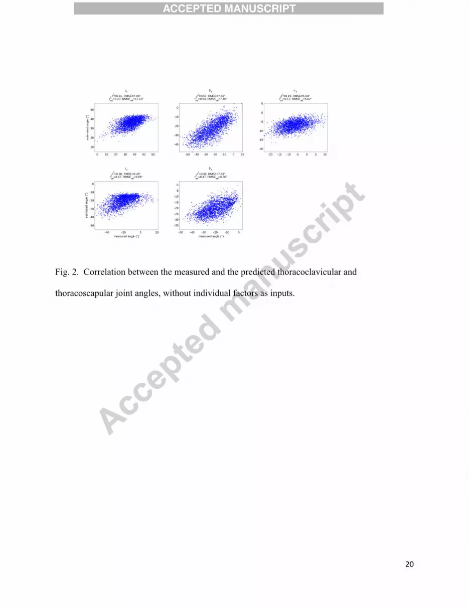
For the second model, based only on the three thoracohumeral angles and excluding the
individual factors, the first step of the regression analysis indicated that all predictors (linear and
quadratic terms of the thoracohumerual joint angles) contributed to all the thoracoclavicular and
thoracoscapular joint angles (Table 5). The medial / lateral rotation of the thoracoscapular joints
had the greatest r2 value of 0.57 and the anterior / posterior tilt of the thoracoscapular joints had
the least r2 value of 0.19 (Figure 2). For the validation dataset, the r2 value ranged between 0.10
and 0.68, The RMSE of the model ranged between 5.03º and 9.45º, while the RMSE obtained
from the validation dataset ranged from 6.62º and 11.13º.
--------------------
Table 4, Table 5, Figure 1, and Figure 2
--------------------
4. Discussion

10
The goal of this study was to build regression models, with and without individual factors,
to predict the orientation of the clavicle and scapula based on the orientation of the humerus. The
results can be integrated into existing shoulder biomechanical models used for calculating
structural loads. In general, the findings in the current study are consistent with the literature (de
Groot and Brand, 2001; Grewal and Dickerson, 2013; Hogfors et al., 1991). For example, the
positive correlation between the elevation of the thoracohumerual joint and the retraction of the
thoracoclavicular joint was observed in previous studies as well as in the current study. The
model performances, as indicated by r2, varied among difference joints. While the models can
best explain the variance of medial / lateral rotation of the thoracoscapular joint, the explanatory
ability for other joints is relatively limited. The value of the RMSE also suggests that error exists
between measured and predicted joint angles.
There were also some differences between the current and previous studies. The RMSEs
of the current models were in the similar range as measured in de Groot and Brand (2001), but
greater than those in Grewal and Dickerson (2013), in general. The r2 in the current study was
also smaller than those in Grewal and Dickerson (2013). In addition, it was found that individual
factors such as age, gender, and anthropometry data were significant predictors for most of the
thoracoclavicular and thoracoscapular joint angles in the current study. Gender differences in
thoracic anthropometry might account for some of the observed variance. The disproportionately
smaller rib cages, and greater rib inclination angles in women than men (Bellemare et al., 2003)
could affect scapular motion patterns. One could also speculate that the significant changes in
scapular motion observed with age might be attributable to morphologic changes, such as
increasing kyphosis (Gayzik et al., 2008). This finding conflicts with those of previous studies.
In de Groot and Brand (2001), it was found that gender and anthropometry data were not

11
significant predictors. In Grewal and Dickerson (2013), age, height, and weight were also
excluded in the regression model due to lack of predictive power. One possible reason for those
inconsistencies is likely due to participant selection. In the current study, the participants were
recruited from the local community and had great diversity in terms of age and weight, while the
participants in those previous studies were mainly young adults. Such great diversity may
contribute to less model predictability and enlarge the effect of the individual factors.
There are limitations to the ability to generalize the results that need to be addressed. First,
all the tested planes of elevation of the thoracohumerual joint were equal or greater than zero.
The predictability of the current model for the postures with negative planes of elevation, such as
those involved in pitching or throwing, remains unclear. Second, the effect of force exertion on
shoulder rhythm was not examined. Results of a previous study (de Groot and Brand, 2001)
indicated that abduction in the plane of elevation can alter the tilt and rotation angle of the
scapula. In general, the current models can be used to describe the shoulder rhythms when the
upper arm is in a positive elevation plane without substantial external load, such as those during
office work or light-duty assembly tasks. However, caution needs to be taken when extrapolating
the current model to untested thoracohumerual joint angles and/or force conditions.
Acknowledgement:
The authors are also grateful to Dr. Chien-chi Chang and Dr. William Horrey for many
useful comments and suggestions and Jacob Banks, Niall O’Brien, and Amanda Rivard for
assistance in data collection.

12
Conflict of Interest Statement:
All authors declare that there is no proprietary, financial, professional or other personal
interest of any nature or kind in any product, service or company that could be construed as
influencing the position presented in this manuscript.
References:
Aiken, L.S., West, S.G., Reno, R.R., 1991. Multiple regression: testing and interpreting interactions. Sage.
Bellemare, F., Jeanneret, A., Couture, J., 2003. Sex differences in thoracic dimensions and configuration.
American Journal of Respiratory and Critical Care Medicine 168, 305-312.
Brochard, S., Lempereur, M., Remy-Neris, O., 2011. Accuracy and reliability of three methods of
recording scapular motion using reflective skin markers. Proceedings of the Institution of
Mechanical Engineers Part H-Journal of Engineering in Medicine 225, 100-105.
de Groot, J.H., Brand, R., 2001. A three-dimensional regression model of the shoulder rhythm. Clinical
Biomechanics 16, 735-743.

13
Dickerson, C.R., Chaffin, D.B., Hughes, R.E., 2007. A mathematical musculoskeletal shoulder model for
proactive ergonomic analysis. Computer Methods in Biomechanics and Biomedical Engineering
10, 389-400.
Gayzik, F.S., Yu, M.M., Danelson, K.A., Slice, D.E., Stitzel, J.D., 2008. Quantification of age-related
shape change of the human rib cage through geometric morphometrics. Journal of Biomechanics
41, 1545-1554.
Grewal, T.-J., Dickerson, C.R., 2013. A novel three-dimensional shoulder rhythm definition that includes
overhead and axially rotated humeral postures. Journal of Biomechanics 46, 608-611.
Hogfors, C., Peterson, B., Sigholm, G., Herberts, P., 1991. Biomechanical model of the human shoulder
joint .2. The shoulder rhythm. Journal of Biomechanics 24, 699-709.
Hogfors, C., Sigholm, G., Herberts, P., 1987. Biomechanical model of the human shoulder .1. Elements.
Journal of Biomechanics 20, 157-166.
Holzbaur, K.R.S., Murray, W.M., Delp, S.L., 2005. A model of the upper extremity for simulating
musculoskeletal surgery and analyzing neuromuscular control. Annals of Biomedical Engineering
33, 829-840.
Inman, V.T., Saunders, J.B., Abbott, L.C., 1944. Observations of the function of the shoulder joint.
Journal of Bone Joint Surgery, 1-30.
Johnson, G.R., Stuart, P.R., Mitchell, S., 1993. A method for the measurement of 3-dimensional scapular
movement. Clinical Biomechanics 8, 269-273.
Karduna, A.R., McClure, P.W., Michener, L.A., Sennett, B., 2001. Dynamic measurements of three-
dimensional scapular kinematics: A validation study. J. Biomech. Eng.-Trans. ASME 123, 184-
190.
Karlsson, D., Peterson, B., 1992. Towards a model for force predictions in the human shoulder. Journal of
Biomechanics 25, 189-199.
Meskers, C.G.M., van de Sande, M.A.J., de Groot, J.H., 2007. Comparison between tripod and skin-fixed
recording of scapular motion. Journal of Biomechanics 40, 941-946.
14
Prinold, J.A.I., Shaheen, A.F., Bull, A.M.J., 2011. Skin-fixed scapula trackers: A comparison of two
dynamic methods across a range of calibration positions. Journal of Biomechanics 44, 2004-2007.
van Andel, C., van Hutten, K., Eversdijk, M., Veeger, D., Harlaar, J., 2009. Recording scapular motion
using an acromion marker cluster. Gait & Posture 29, 123-128.
Wu, G., van der Helm, F.C.T., Veeger, H.E.J., Makhsous, M., Van Roy, P., Anglin, C., Nagels, J.,
Karduna, A.R., McQuade, K., Wang, X.G., Werner, F.W., Buchholz, B., 2005. ISB
recommendation on definitions of joint coordinate systems of various joints for the reporting of
human joint motion - Part II: shoulder, elbow, wrist and hand. Journal of Biomechanics 38, 981-
992.
Figure captions
Fig.1. Correlation between the measured and the predicted thoracoclavicular and
thoracoscapular joint angles, with individual factors as inputs.
Fig. 2. Correlation between the measured and the predicted thoracoclavicular and
thoracoscapular joint angles, without individual factors as inputs.

15
Table 1
The 118 static thoracohumerual joint angles tested in the current study. γTH1_f, βTH_f, and γTH1_f
are plane of elevation, elevation angle, and axial rotation defined by the frame, respectively. The
lower case “f” stands for “frame-defined”.
γTH1
_f βTH
_f γTH2
_f γTH1
_f βTH
_f γTH2
_f γTH1
_f βTH
_f γTH2
_f γTH1
_f βTH
_f γTH2
_f γTH1
_f βTH
_f γTH2
_f
0 0 -60 30 30 -90 60 30 -90 90 30 -90 120 30 -90 0 0 -30 30 30 -60 60 30 -60 90 30 -60 120 30 -60 0 0 0 30 30 -30 60 30 -30 90 30 -30 120 30 -30 0 0 30 30 30 0 60 30 0 90 30 0 0 0 60 30 30 30 60 30 30 120 60 -90
90 60 -90 120 60 -60 0 30 -90 30 60 -90 60 60 -90 90 60 -60 120 60 -30 0 30 -60 30 60 -60 60 60 -60 90 60 -30 120 60 0 0 30 -30 30 60 -30 60 60 -30 90 60 0 0 30 0 30 60 0 60 60 0 90 60 30 120 90 -90 0 30 30 30 60 30 60 60 30 120 90 -60
90 90 -90 120 90 -30 0 60 -90 30 90 -90 60 90 -90 90 90 -60 120 90 0 0 60 -60 30 90 -60 60 90 -60 90 90 -30 0 60 -30 30 90 -30 60 90 -30 90 90 0 120 120 -90 0 60 0 30 90 0 60 90 0 90 90 30 120 120 -60 0 60 30 30 90 30 60 90 30 120 120 -30
30 90 60 90 120 -90 120 120 0 0 90 -90 60 120 -90 90 120 -60 120 120 30 0 90 -60 30 120 -90 60 120 -60 90 120 -30 0 90 -30 30 120 -60 60 120 -30 90 120 0 120 150 0 0 90 0 30 120 -30 60 120 0 90 120 30 120 150 30 0 90 30 30 120 0 60 120 30 120 150 60 0 90 60 30 120 30 90 150 -90 120 150 90
30 120 60 60 150 -90 90 150 30 0 120 -90 60 150 -60 0 120 -60 30 150 -90 60 150 -30 0 120 -30 30 150 -60 60 150 0 0 120 0 30 150 -30 60 150 30 0 120 30 30 150 0
16
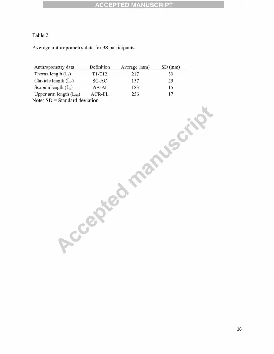
Table 2
Average anthropometry data for 38 participants.
Anthropometry data Definition Average (mm) SD (mm) Thorax length (Lt) T1-T12 217 30 Clavicle length (Lc) SC-AC 157 23 Scapula length (Ls) AA-AI 183 15 Upper arm length (Lua) ACR-EL 256 17
Note: SD = Standard deviation
17
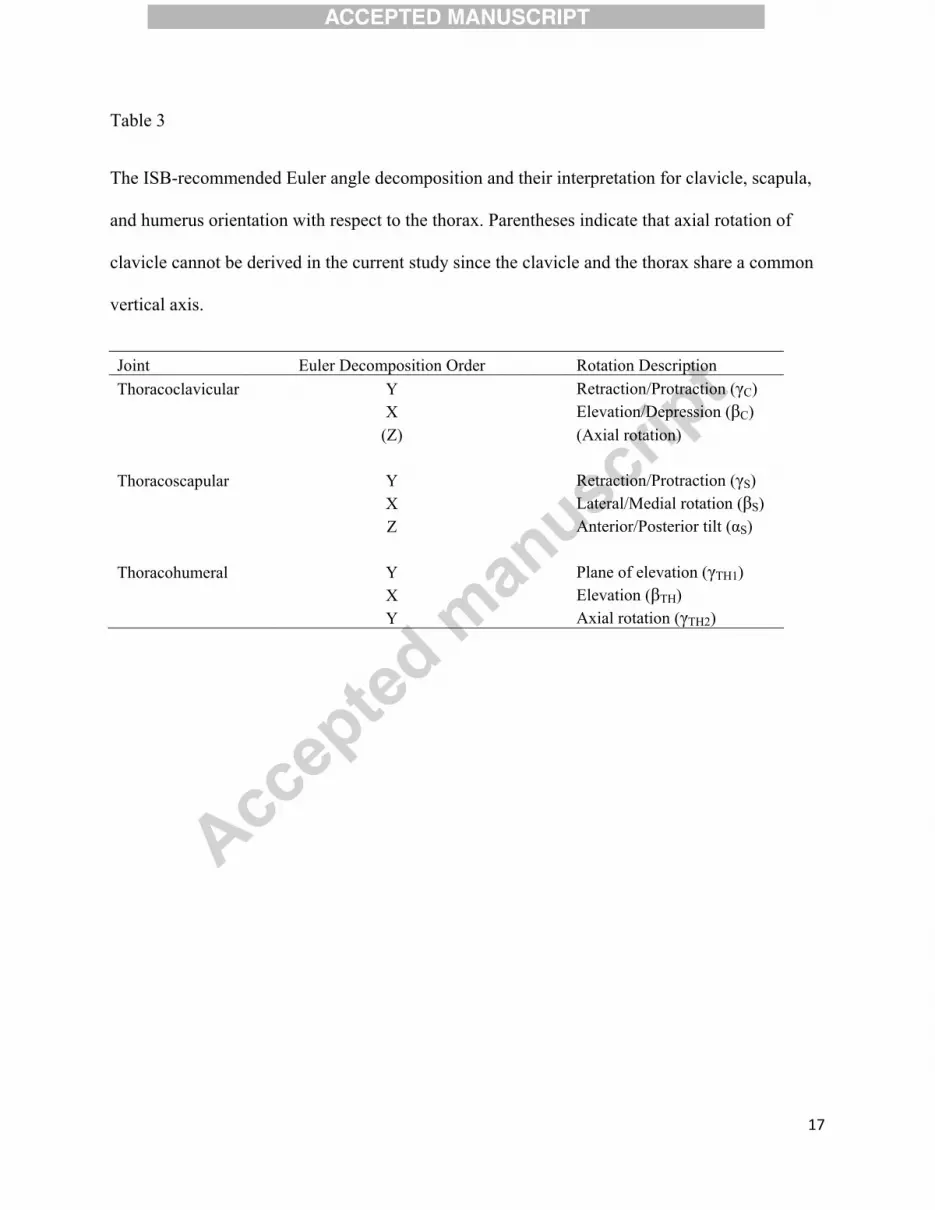
Table 3
The ISB-recommended Euler angle decomposition and their interpretation for clavicle, scapula,
and humerus orientation with respect to the thorax. Parentheses indicate that axial rotation of
clavicle cannot be derived in the current study since the clavicle and the thorax share a common
vertical axis.
Joint Euler Decomposition Order Rotation Description Thoracoclavicular Y Retraction/Protraction (γC)
X Elevation/Depression (βC) (Z) (Axial rotation)
Thoracoscapular Y Retraction/Protraction (γS) X Lateral/Medial rotation (βS) Z Anterior/Posterior tilt (αS)
Thoracohumeral Y Plane of elevation (γTH1) X Elevation (βTH) Y Axial rotation (γTH2)

18
Table 4
The regression equation of shoulder rhythm with individual factors.
Y c1 c2 c3 c4 c5 c6 c7 c8 c9 c10 c11 c12 c13 c14 c15 Const.
γS
0.160
-0.013
0.041
-0.0013
-0.0015
-0.0002
-0.0022
-0.0006
0.0003
1.565
0.100
- 0.033
-0.026
-0.211
37.89
βS
-0.076
0.332
-0.027
-0.0006
-0.0015
- -0.0006
-0.0017
-0.0003
-2.651
-0.220
- 0.062
-0.099
0.143
-22.35
αS
0.054
-0.037
-0.010
0.0002
0.0003
0.0002
- 0.0006
0.0008
2.432
-0.085
- 0.029
-0.064
-0.073
-7.50
γC
0.068
0.199
0.011
-0.0017
-0.0026
-0.0004
-0.0017
-0.0018
- / / 0.029
-0.080
- -0.248
-17.42
βC
-0.024
0.201
-0.033
- - 0.0003
-0.0006
-0.0003
0.0006
-1.222
-0.233
-0.068
0.066
0.127
-0.048
-21.04
The equations are in the form Y = c1(γTH1-46.97) + c2(βTH +66.46) + c3(γTH2+37.64) + c4(γTH1-
46.97)2 + c5(βTH +66.46)2 + c6(γTH2+37.64)2 + c7(γTH1-46.97) (βTH +66.46) + c8(γTH1-46.97)
(γTH2+37.64) + c9(βTH +66.46) (γTH2+37.64) + c10·gender + c11(age-33.31) + c12(Lb-218.9) +
c13(Lc-157.8) + c14(Ls-182.1) + c15(Lua-259.2) + Const. Gender is -1 for female and 1 for male. Lt,
Lc, Ls, and Lua are the length of body, clavicle, scapula, and upper arm, respectively, with a unit
of millimeter. “/” indicates the term was eliminated in the first step of regression analysis, while
a “-” indicates the term was eliminated in the second step by the stepwise regression.

19
Table 5
The regression equation of shoulder rhythm without individual factors.
Y
Const.
γS 0.163 - 0.039 -0.0016
-0.0018
-0.0003
-0.0023
-0.0009
0.0003 38.35
βS -0.065
0.322 -0.024
- -0.0009
- - -0.0014
- -23.20
αS 0.060 -0.039
-0.011
- - 0.0002 - 0.0005 0.0008 -7.11
γC 0.059 0.207 0.013 -0.0017
-0.0025
-0.0005
-0.0020
-0.0020
- -17.42
βC -0.025
0.204 -0.031
- - 0.0002 -0.0007
-0.0003
0.0007 -21.04
The equations are in the form Y = (γTH1-46.97) + (βTH +66.46) + (γTH2+37.64) +
(γTH1-46.97)2 + (βTH +66.46)2 + (γTH2+37.64)2 + (γTH1-46.97) (βTH +66.46) + (γTH1-
46.97) (γTH2+37.64) + (βTH +66.46) (γTH2+37.64). “-” indicates the term is eliminated by the
stepwise regression.
0 10 20 30 40 50 60
10
20
30
40
50
γs
r2=0.43, RMSE=6.43°rval2 =0.25, RMSEval=10.39°
estim
ated
ang
le (
°)
-60 -40 -20 0-50
-40
-30
-20
-10
0
βs
r2=0.65, RMSE=7.00°rval2 =0.68, RMSEval=7.02°
-20 -15 -10 -5 0 5 10-20
-15
-10
-5
0
5
αs
r2=0.32, RMSE=4.63°rval2 =0.10, RMSEval=6.92°
-40 -20 0 20
-50
-40
-30
-20
-10
0
γc
r2=0.45, RMSE=8.27°rval2 =0.39, RMSEval=8.30°
estim
ated
ang
le (
°)
measured angle (°)-50 -40 -30 -20 -10 0
-35
-30
-25
-20
-15
-10
-5
0
βc
r2=0.49, RMSE=6.80°rval2 =0.49, RMSEval=7.34°
measured angle (°)
Fig.1. Correlation between the measured and the predicted thoracoclavicular and
thoracoscapular joint angles, with individual factors as inputs.
20
0 10 20 30 40 50 60
10
20
30
40
50
γs
r2=0.31, RMSE=7.06°rval2 =0.20, RMSEval=11.13°
estim
ated
ang
le (
°)
-50 -40 -30 -20 -10 0 10
-40
-30
-20
-10
0
βs
r2=0.57, RMSE=7.83°rval2 =0.64, RMSEval=7.40°
-20 -15 -10 -5 0 5 10
-20
-15
-10
-5
0
5
αs
r2=0.19, RMSE=5.04°rval2 =0.12, RMSEval=6.62°
-40 -20 0 20
-50
-40
-30
-20
-10
0
γc
r2=0.28, RMSE=9.45°rval2 =0.47, RMSEval=6.89°
estim
ated
ang
le (
°)
measured angle (°)-50 -40 -30 -20 -10 0
-35
-30
-25
-20
-15
-10
-5
0
βc
r2=0.35, RMSE=7.63°rval2 =0.47, RMSEval=6.86°
measured angle (°)
Fig. 2. Correlation between the measured and the predicted thoracoclavicular and
thoracoscapular joint angles, without individual factors as inputs.


![[Reconstruction following shoulder resection for bone tumor]](https://img.dokumen.tips/doc/110x75/634ed0e73bdc8e8810081587/reconstruction-following-shoulder-resection-for-bone-tumor.jpg)


