Embed Size (px)
Citation preview

A Distributed Architecture for Autonomous UnmannedAerial Vehicle Experimentation
P. Doherty, P. Haslum, F. Heintz, T. Merz, P. Nyblom, T. Persson, and B. Wingman
Linkoping UniversityDept. of Computer and Information ScienceSE-58183 Linkoping, [email protected]
In Proceedings of the 7th International Symposium on Distributed Autonomous Sys-tems, 2004.
Summary. The emerging area of intelligent unmanned aerial vehicle (UAV) research has shownrapid development in recent years and offers a great number of research challenges for distributedautonomous robotics systems. In this article, a prototype distributed architecture for autonomous un-manned aerial vehicle experimentation is presented which supports the development of intelligentcapabilities and their integration in a robust, scalable, plug-and-play hardware/software architecture.The architecture itself uses CORBA to support its infrastructure and it is based on a reactive concentricsoftware control philosophy. A research prototype UAV system has been built, is operational and isbeing tested in actual missions over urban environments.
1 Introduction
The emerging area of intelligent unmanned aerial vehicle (UAV) research has shown rapiddevelopment in recent years and offers a great number of research challenges in the area ofdistributed autonomous robotics systems. Much previous research has focused on low-levelcontrol capability with the goal of developing controllers which support the autonomousflight of a UAV from one way-point to another. The most common type of mission sce-nario involves placing sensor payloads in position for data collection tasks where the data iseventually processed off-line or in real-time by ground personnel. Use of UAVs and missiontasks such as these have become increasingly more important in recent conflict situationsand are predicted to play increasingly more important roles in any future conflicts.
Intelligent UAVs will play an equally important role in civil applications. For both mil-itary and civil applications, there is a desire to develop more sophisticated UAV platformswhere the emphasis is placed on development of intelligent capabilities and on abilities tointeract with human operators and additional robotic platforms. Focus in research has movedfrom low-level control towards a combination of low-level and decision-level control inte-grated in sophisticated software architectures. These in turn, should also integrate well withlarger network-centric based C4I2 systems. Such platforms are a prerequisite for supportingthe capabilities required for the increasingly more complex mission tasks on the horizon andan ideal testbed for the development and integration of distributed AI technologies.

The WITAS1 Unmanned Aerial Vehicle Project2 [4] is a basic research project whosemain objectives are the development of an integrated hardware/software VTOL (VerticalTake-Off and Landing) platform for fully-autonomous missions and its future deploymentin applications such as traffic monitoring and surveillance, emergency services assistance,photogrammetry and surveying.
Fig. 1. Aerial photo overRevinge, Sweden
Basic and applied research in the project covers a widerange of topics which include the development of a dis-tributed architecture for autonomous unmanned aerial vehi-cles. In developing the architecture, the larger goals of in-tegration with human operators and other ground and aerialrobotics systems in network centric C4I2 infrastructures hasbeen taken into account and influenced the nature of the basearchitecture. In addition to the software architecture, manyAI technologies have been developed such as path planners,chronicle recognition and situational awareness techniques.The architecture supports modular and distributed integra-tion of these and any additional functionalities added in thefuture. The WITAS UAV hardware/software platform hasbeen built and successfully used in a VTOL system capa-ble of achieving a number of complex autonomous missions flown in an interestingur-ban environment populated with building and road structures. In one mission, the UAVautonomously tracked a moving vehicle for up to 20 minutes. In another, several buildingstructures were chosen as survey targets and the UAV autonomously generated a plan to flyto each and take photos of each of its facades and then successfully executed the mission.
Fig. 2.The WITAS RMAX Helicopter
Figure 1 shows an aerial photo of our pri-mary testing area located in Revinge, Swe-den. An emergency services training schoolis located in this area and consists of a col-lection of buildings, roads and even makeshiftcar and train accidents. This provides an idealtest area for experimenting with traffic surveil-lance, photogrammetric and surveying scenar-ios, in addition to scenarios involving emer-gency services. We have also constructed anaccurate 3D model for this area which hasproven invaluable in simulation experimentsand parts of which have been used in the on-board GIS.
In the remainder of the paper, we will focus primarily on a description of the engineeredon-board system itself, parts of the distributed CORBA-based software architecture and in-teraction with the primary flight control system. There are a great many topics that willnot be considered due to page limitations, particularly in the area of knowledge represen-tation [5, 7, 8], symbol grounding [14, 13], and deliberative capabilities [24, 6], task-basedplanning [6], specific control modes [3, 16, 27] and their support, image processing [18]
1WITAS (pronouncedvee-tas) is an acronym for the Wallenberg Information Technology andAutonomous Systems Laboratory at Linkoping University, Sweden.
2This work and the project is funded by a grant from the Wallenberg Foundation.

and in technologies such as dialogue management for support of ground operation person-nel [26].
2 The VTOL and Hardware Platform
RTLINUX
RTLINUX
TCP/IP
700Mhz PIII/256Mbram/500Mbflash
700Mhz PIII/256Mbram/500Mbflash
700Mhz PIII/256Mbram/256Mbflash
GPS
serial analog
magneticcompass
pressuresensor
temp.sensors
cameracontrol
framegrabberBT878
preprocessor
IPAPI
pathplanner
taskplanner
knowledgerepository
TP exec
chroniclerecognition
GIS
DOR
Other. . .
Helicopter Control
RMAX HelicopterPlatform
YamahaAttitudeController
roll
yaw
pitch
200Hz
50Hz
Camera Platform
Color CCD Camera/PTU
mini-dv
YamahaAttitudeSensors
200/66Hz
LINUX
RS232
sonar
Fig. 3.On-Board Hardware Schematic
The WITAS Project UAV platform we use isa slightly modified Yamaha RMAX (figure 2).It has a total length of 3.6 m (incl. main ro-tor), a maximum take-off weight of 95 kg,and is powered by a 21 hp two-stroke engine.Yamaha equipped the radio controlled RMAXwith an attitude sensor (YAS) and an atti-tude control system (YACS). Figure 3 showsa high-level schematic of the hardware plat-form that we have built and integrated with theRMAX platform.
The hardware platform consists of threePC104 embedded computers (figure 3). Theprimary flight control (PFC) system consistsof a PIII (700Mhz) processor, a wireless Eth-ernet bridge and the following sensors: a RTKGPS (serial), and a barometric altitude sensor(analog). It is connected to the YAS and YACS(serial), the image processing computer (se-rial) and the deliberative computer (Ethernet).The image processing (IP) system consistsof a second PC104 embedded computer (PIII700MHz), a color CCD camera (S-VIDEO,serial interface for control) mounted on a pan/tilt unit (serial), a video transmitter (com-posite video) and a recorder (miniDV). The deliberative/reactive (D/R) system runs on athird PC104 embedded computer (PIII 700MHz) which is connected to the PFC systemwith Ethernet using CORBA event channels. The D/R system is described in more detail insection 4.
3 Control
A great deal of effort has gone into the development of a control system for the WITAS UAVwhich incorporates a number of different control modes and includes a high-level interfaceto the control system. This enables other parts of the architecture to call the appropriatecontrol modes dynamically during the execution of a mission. The ability to switch modescontingently is a fundamental functionality in the architecture and can be programmed intothe task procedures associated with the reactive component in the architecture. We devel-oped and tested the following autonomous flight control modes:
• take-off (TO-Mode) and landing via visual navigation (L-Mode, see [16])• hovering (H-Mode)• dynamic path following (DPF-Mode, see [3])• reactive flight modes for interception and tracking (RTF-Mode).

These modes and their combinations have been successfully demonstrated in a numberof missions at the Revinge testflight area. The primary flight control system (bottom PC104in Figure 3) can be described conceptually as consisting of a device, reactive, behavior andapplication layer as depicted in figure 4a.3Each layer consists of several functional unitswhich, with the exception of the application layer, are executed periodically with compara-ble period and worst case execution times. The implementation is based on RTLinux (GPL),which runs an ordinary Linux distribution as a task with lower priority. The application layeris realized in user space as no hard real-time execution is required, while the other layerscontain functional units running as kernel modules in hard real-time.
A CORBA interface is set up between the PFC system and the deliberative/reactive sys-tem of the software architecture (top PC104 in Figure 3). Network communication betweenthe two is physically realized using Ethernet with CORBA event channels and CORBAmethod calls. Task procedures in the D/R system issue commands to the PFC system toinitiate different flight modes and receive helicopter states and events from the PFC systemwhich influence the activity of the task procedure.
image processing modulesimage acquisition
serial communication
PFC comm. pan/tilt driver camera driver
pan/tilt control camera control
image processing HCSM
b)
analog I/O
vehicle control
sensor drivers
continuousset−point gen.
IPC/GCS comm.
processingsensor signalstate analysis
digital I/O
actuator drivers
simulationvehicle/sensor
serial comm.
primary flight control HCSM
CORBA interface / user HCSMuser interfacea)
idle
braking take off
hovering
TakeOffMode
proportionalnavigation
landing
BrakeMode
HoverMode
DynPathMode
trackingobject
TrackMode
dyn. path following
ModeSwitch
LandMode
PropMode
manual
IPSystem
Interface
auto
1ModeSwitch
2
3
...
�������
������� �������
�������
� ����� ������������� � !�"
#%$ !'&(� � !�"�) *,+.-0/21
354 ���6&87:9 4<;>= ��? 4 !@1�A
BDC ���6&87:9 4<;>= ��? 4 !@1
BDC ���6&�9 4<;>= ��? 4 !E1
#%$ !'&F�G� !�"�)GHJI���*%1 �������
3K4 ���6&�9 4<;>= ��? 4 !E1LA� ����� ;>= ��? 4 !��G� !�"5M� ����� NO".PQ!SR
#%$ !'&(� � !�"�) TVUSWSYX[Z\1
#%$ !'&F�G� !�"�) T]+^US_`WQ1
#%$ !'&(� � !�"�)Ga\-cbS +�1
&F�G� !�"�)Gd<US���e1#%$ !
354 ���
f ?��Fgc"E&(h = P�iQ"Kj�k,���ml`�
. �2��� B $ h = P�iQ"
� �����onJ?��m�c�����������f ?��Fgc"<&8nJ?��p�qj�k,���ml`�D1LA
.o����� �rP 4 ?2PS�F�����������f ?��Fgc"<&87�nJ?e�m�qj�k,���ml`�D1LA
3K4 ���LAs� ��� � �rP 4 ?2PS�F�����������
t nJ?��p�qj�k,���ml`�D1LA
Fig. 4.PFC and IP System Schematic (left) and HCSMs for Flight Mode Switching (right)
Hierarchical concurrent state machines (HCSMs) are used to represent states of the PFCsystem. HCSMs are mixed Mealy and Moore machines with hierarchical and orthogonaldecomposition. These are executed explicitly in the PFC system. We use a visual formalismsimilar to Harel’s statecharts [12] to describe HCSMs.
Figure 4b shows that part of the flight control HCSM involving mode switching fordifferent flight modes.4
3The image processing (IP) system (middle PC104 in Figure 3) has a similar structure, but willnot be considered in this paper.
4Nested state machines are symbolized as rectangular boxes in a state node,Pulseis an event sentperiodically,Init triggers a transition from an entry state (circular node) when condition holds,Exit
4 Software System
A great deal of effort in the artificial intelligence community has recently been directedtowards deliberative/reactive control architectures for intelligent robotic systems. Two goodsources of reference are [1] and [15]. Many of the architectures proposed can be viewedin a loose sense as layered architectures with a control, a reactive and a deliberative layer(see [9]). The software architecture we have developed does have deliberative, reactive andcontrol components, but rather than viewing it from the perspective of a layered architecture,it is best viewed as areactive concentricarchitecture which uses services provided by boththe deliberative and control components in a highly distributed and concurrent manner. Atany time during the execution of a mission, a number of interacting concurrent processes atvarious levels of abstraction, ranging from high-level services such as path planners to low-level services such as execution of control laws, are being executed with various latencies.
We have chosen CORBA5 as a basis for the design and implementation of a looselycoupled distributed software architecture for our aerial robotic system. We believe this isa good choice which enables us to manage the complexity of a deliberative/reactive (D/R)software architecture with as much functionality as we require for our applications. It alsoensures clean and flexible interfacing to the deliberative and control components in additionto the hardware platform via the use of IDL (Interface Definition Language).
GeographicalData
Repository
KnowledgeRepository
DynamicObject
Repository
Task Procedure ExecutionModule (TPEM)
TP1 TPn
PredictionService
ChronicleRecognition
Service
Path PlannerService
Task PlannerService
HelicopterController
PhysicalCamera
Controller
ImageController
IPAPI
IPAPI RuntimeImage Processing Module (IPM)
QualitativeSignal Processing
Controller
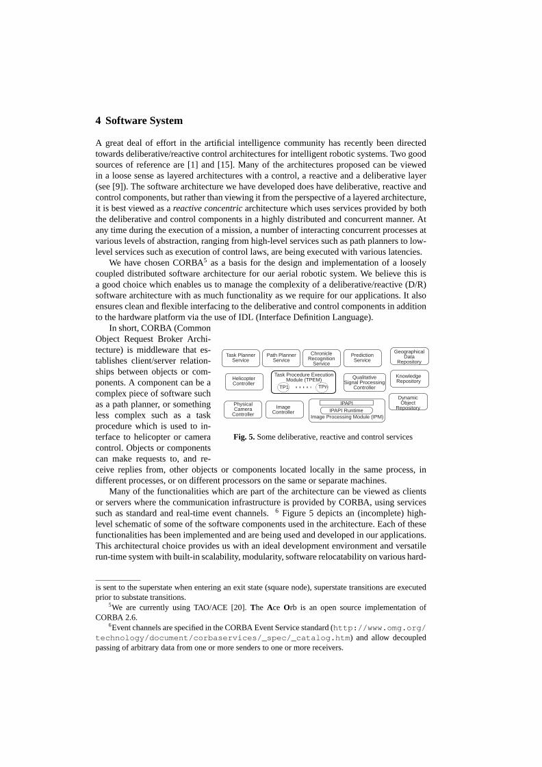
Fig. 5.Some deliberative, reactive and control services
In short, CORBA (CommonObject Request Broker Archi-tecture) is middleware that es-tablishes client/server relation-ships between objects or com-ponents. A component can be acomplex piece of software suchas a path planner, or somethingless complex such as a taskprocedure which is used to in-terface to helicopter or cameracontrol. Objects or componentscan make requests to, and re-ceive replies from, other objects or components located locally in the same process, indifferent processes, or on different processors on the same or separate machines.
Many of the functionalities which are part of the architecture can be viewed as clientsor servers where the communication infrastructure is provided by CORBA, using servicessuch as standard and real-time event channels.6 Figure 5 depicts an (incomplete) high-level schematic of some of the software components used in the architecture. Each of thesefunctionalities has been implemented and are being used and developed in our applications.This architectural choice provides us with an ideal development environment and versatilerun-time system with built-in scalability, modularity, software relocatability on various hard-
is sent to the superstate when entering an exit state (square node), superstate transitions are executedprior to substate transitions.
5We are currently using TAO/ACE [20].The Ace Orb is an open source implementation ofCORBA 2.6.
6Event channels are specified in the CORBA Event Service standard (http://www.omg.org/technology/document/corbaservices/_spec/_catalog.htm ) and allow decoupledpassing of arbitrary data from one or more senders to one or more receivers.
ware configurations, performance (real-time event channels and schedulers), and support forplug-and-play software modules.
4.1 The Modular Task Architecture
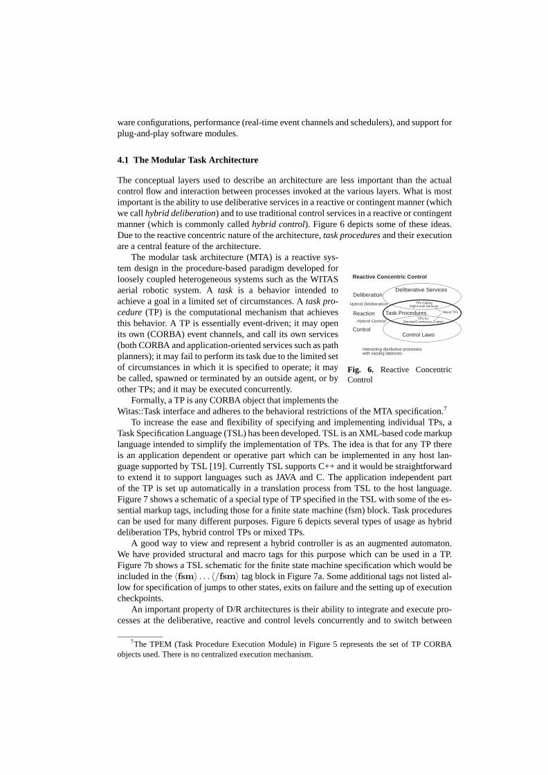
The conceptual layers used to describe an architecture are less important than the actualcontrol flow and interaction between processes invoked at the various layers. What is mostimportant is the ability to use deliberative services in a reactive or contingent manner (whichwe callhybrid deliberation) and to use traditional control services in a reactive or contingentmanner (which is commonly calledhybrid control). Figure 6 depicts some of these ideas.Due to the reactive concentric nature of the architecture,task proceduresand their executionare a central feature of the architecture.
Deliberation
Reaction
Control
Hybrid Deliberation
Hybrid Control
Deliberative Services
Control Laws
Task Procedures
TPs CallingHigh-Level Services
TPs forDiscrete/Continuous Control
Reactive Concentric Control
Interacting disributive processeswith varying latencies
Mixed TPs
Fig. 6. Reactive ConcentricControl
The modular task architecture (MTA) is a reactive sys-tem design in the procedure-based paradigm developed forloosely coupled heterogeneous systems such as the WITASaerial robotic system. Atask is a behavior intended toachieve a goal in a limited set of circumstances. Atask pro-cedure(TP) is the computational mechanism that achievesthis behavior. A TP is essentially event-driven; it may openits own (CORBA) event channels, and call its own services(both CORBA and application-oriented services such as pathplanners); it may fail to perform its task due to the limited setof circumstances in which it is specified to operate; it maybe called, spawned or terminated by an outside agent, or byother TPs; and it may be executed concurrently.
Formally, a TP is any CORBA object that implements theWitas::Task interface and adheres to the behavioral restrictions of the MTA specification.7
To increase the ease and flexibility of specifying and implementing individual TPs, aTask Specification Language (TSL) has been developed. TSL is an XML-based code markuplanguage intended to simplify the implementation of TPs. The idea is that for any TP thereis an application dependent or operative part which can be implemented in any host lan-guage supported by TSL [19]. Currently TSL supports C++ and it would be straightforwardto extend it to support languages such as JAVA and C. The application independent partof the TP is set up automatically in a translation process from TSL to the host language.Figure 7 shows a schematic of a special type of TP specified in the TSL with some of the es-sential markup tags, including those for a finite state machine (fsm) block. Task procedurescan be used for many different purposes. Figure 6 depicts several types of usage as hybriddeliberation TPs, hybrid control TPs or mixed TPs.
A good way to view and represent a hybrid controller is as an augmented automaton.We have provided structural and macro tags for this purpose which can be used in a TP.Figure 7b shows a TSL schematic for the finite state machine specification which would beincluded in the〈fsm〉 . . . 〈/fsm〉 tag block in Figure 7a. Some additional tags not listed al-low for specification of jumps to other states, exits on failure and the setting up of executioncheckpoints.
An important property of D/R architectures is their ability to integrate and execute pro-cesses at the deliberative, reactive and control levels concurrently and to switch between
7The TPEM (Task Procedure Execution Module) in Figure 5 represents the set of TP CORBAobjects used. There is no centralized execution mechanism.

〈tp name = T askname〉〈declarations〉
〈parameter . . . /〉 . . . 〈parameter . . . /〉// other declarations, e.g. local variables and constants
〈/declarations〉〈services〉
// CORBA server objects, event channels used, etc.〈/services〉〈init〉
// Host code for task specific initialization〈/init〉〈destroy〉
// Host code for task specific cleanup// CORBA cleanup handled automatically
〈/destroy〉〈function〉 . . . 〈/function〉 . . . //more fns〈start〉
// Executed with call to TP start() method// Host code plus host code macros// Typically will perform some setup then// a 〈jump〉 to FSM state
〈/start〉〈fsm〉
// Main behavioral specification in form// of a finite state machine
〈/fsm〉〈/tp〉
(a) TSL tags and partial schematicfor a TP specification.
〈fsm〉〈statename =sname〉〈action〉
// Executed whenever TP enters this state〈/action〉
// State specific reactions to events〈reaction event = ”event name”〉 . . . 〈/reaction〉
.
.
.〈reaction event = ”event name”〉 . . . 〈/reaction〉〈/state〉
//More state specifications. . .
// Global reactions to events〈reaction〉 . . . 〈/reaction〉
.
.
.〈reaction〉 . . . 〈/reaction〉〈/fsm〉
(b) TSL tags and partial schematic foran fsm specification
Fig. 7.TP Specifications with TSL tags.
them seamlessly. Reactive components must be able to interface in a clean manner to heli-copter and camera control and adapt activity to contingencies in the environment in a timelymanner. Likewise, they must be able to interface to deliberative services in a clean man-ner. Consequently, use of TPs for hybrid control and hybrid deliberation is of fundamentalimportance. An example is provided in the following section.
4.2 Using Task Procedures for Flight Control
In this section, the interface between TPs for hybrid control and flight control modes, inaddition to some limited hybrid deliberation, will be described. The main ingredients areTPs in the shape of finite state machines and the use of a declarative flight command lan-guage (FCL). Events from the flight controller (passed via event channels) create a par-tial view of the state of the UAV. Based on this, and its own state, a TP can dynami-cally generate appropriate flight commands, which are sent back to the control system.
Lock UAVto position pathplanner
Wait for CallFlyPath
UAV stable path ready finished
UAV off courseno path found fail (other reson)
FAIL
EXIT
Fig. 8.TheNavToPt automaton
Suppose the UAV has been giventhe task of finding and tracking a vehi-cle with a particular signature, believedto be in a certain region of Revinge. ATP for such a mission consists of sev-eral subtasks, each carried out by thetop-level TP invoking other TPs: Thefirst isNavToPt (depicted in Figure 8),which navigates the UAV safely to awaypoint in the region of interest (ROI).
To do so,NavToPt makes use of both deliberative and control services. First, it callsa path planning service [25] which provides a (segmented) path from the UAVs currentposition to the waypoint (provided such a path can be found). Then, it invokes aFlyPath TP

which takes care of passing the path segments, target velocity and other parameters to thedynamic path following flight mode in the control system. During flight,FlyPath receivesevents from the control system (via event channels) and responds appropriately, for exampleissuing a command to enter hovering mode when the end of the last path segment is reached.It also generates events reporting on the progress of the flight, which are in turn monitoredby NavToPt.
Once the UAV has arrived at the goal point, the parent TP configures and starts im-age processing services [18] to attempt identification of vehicles in the area. If a vehiclematching the initial signature is found, the parent TP starts a new TPFlyTo (see Figure9) which uses proportional navigation mode [27], one of the existing RTF-modes, to posi-tion the UAV relative to the vehicle. Since the vehicle is probably moving,FlyTo instanceswill be continually terminated and restarted with new parameters. Each instance ofFlyTo,while running, generates a stream of flight commands passed to the PFC system, wherethey are handled by the PN flight mode functional unit, and receives a stream of eventsfrom the flight control system and image processing system. Both automata described arein fact implemented using TPs with structure similar to that in the two TSL schemata.
FlyToaligned
Init
Align
Climb
not aligned
aligned
not aligned
not at altitude
at altitude
closingBrake
at position
not aligned
Holdexit
closing
Fig. 9.TheFlyTo automaton
The flight command language (FCL)is used to bridge the abstraction gapbetween task procedures in the reac-tive component and flight and cam-era modes in the control component.Figure 10 shows a number of repre-sentative flight commands used for theproportional navigation flight controlmode.
In this case the PN mode is con-trolled by providing commands toXY,Z andYaw channels, in addition to anadministration channel. The adminis-tration channel is used to set variousparameters. It is also used to inform thePN mode which object to fly to (FlyObject), this may be a waypoint or a moving object onthe ground previously identified, and the object to look at with the camera (LookObject).Additional flight commands are provided for other flight control modes and camera control.In the case of dynamic path following, representations of parameterized curves are passedas arguments to flight commands, these arguments are generated via a task procedure call tothe path planning service.
XY Channel Z ChannelCruise(), SlowDown() Land(), FlyAtAltitude()Slow(), Brake() ClimbTo()FlyToFlyObject(), FlyWithVelocity() Yaw ChannelFlyTowards(), LockOnFlyObject() FlyWithYaw(), FlyWithYawOfYourself()LockOnPosition(), LockOnLookObject() FlyCleanly()
Fig. 10.Representative Flight Commands for Proportional Navigation.
4.3 Benefits of the Approach
The use of TSL with XML markup tags and a host language translator provides a modular,extensible means of constructing and experimenting with TPs that hides the syntactic over-head associated with initialization of CORBA event channels, services and error handlingcode. Each TP is automatically generated as a standard CORBA object and can be spawnedor terminated using the Witas::Task interface. We believe that the greatest flexibility is pro-vided if the actual semantic content of a TP can be specified in a familiar language such asC++ or Java. The structuring of code in this manner also provides a clean way to analyzethe behavior of a TP formally. The use of a flight command language provides a smoothtransition from discrete to continuous control behavior between the reactive and controlcomponents.
New control modes can be added in a modular manner and interfaced by adding newflight commands. The flight command streams themselves can be generated and analyzed inmany different ways. The use of event channels and filters by TPs also provides a flexiblemeans of dynamically constructing partial state representations which drive the behaviors ofTPs. In a similar manner, deliberative functionalities can be modularly added and packagedas CORBA objects. These may include legacy code. For example, the chronicle recognitionsoftware used is based on IXTET [11]8 and is wrapped directly as a CORBA object . Theseobjects may physically be distributed between the UAV itself and various ground stations.This is useful if the computational resources required for a service exceed those providedby the UAV platform.
5 Related Work
There is, without a doubt, much activity with UAVs in the military sector, primarily withfixed-wing high altitude vehicles. Much of the focus is on design of physical platforms, low-level control, and sensing [21]. Less focus has been placed on the type of system describedhere. This also applies to the majority of commercial attempts at marketing UAVs, althoughhere, there has been more activity with VTOL platforms. Academic research with UAVs isincreasing at a rapid pace. Here again, the majority of projects have focused on low-levelcontrol, although there is more activity with software architectures and integration of somedeliberative capabilities. The work closest to ours is that being pursued at Georgia Tech[10].Rather than list publications, we refer the reader to the following (non-exhaustive) list ofwebsites for information about interesting university and institute UAV activities: GeorgiaTech[10], M.I.T[17], Carnegie-Mellon[2], U. of C., Berkeley[29], Stanford University[28],ONERA RESSAC [22].
References
1. R. C. Arkin.Behavior-Based Robotics. MIT Press, 1998.2. Carnegie Mellon University. http://www.ri.cmu.edu/projects/project_93.
html .3. G. Conte, S. Duranti, and T. Merz. Dynamic 3D path following for an autonomous helicopter. In
Proceedings of the 5th IFAC Symposium on Intelligent Autonomous Vehicles, 2004.
8In fact, we use a new implementation, CRS, developed by C. Dousson at France Telecom (http://crs.elibel.tm.fr/en/ ).

4. P. Doherty, G. Granlund, K. Kuchcinski, K. Nordberg, E. Sandewall, E. Skarman, and J. Wiklund.The WITAS unmanned aerial vehicle project. InProceedings of the 14th European Conferenceon Artificial Intelligence, pages 747–755, 2000.http://www.liu.se/ext/witas .
5. P. Doherty, J. Kachniarz, and A. Szałas. Using contextually closed queries for local closed-worldreasoning in rough knowledge databases. In[23] , 2003.
6. P. Doherty and J. Kvarnstrom. TALplanner: A temporal logic based planner. InAI Magazine,volume 22, pages 95–102. AAAI Press, 2001.
7. P. Doherty, W. Łukaszewicz, A. Skowron, and A. Szałas. Combining rough and crisp knowledgein deductive databases. In[23] , 2003.
8. P. Doherty, W. Łukaszewicz, and A. Szałas. Approximative query techniques for agents usingheterogenous ontologies. InInt’l Conference on Principles of Knowledge Representation andReasoning (KR-04), 2004.
9. E. Gat. Three-layer architectures. In D. Kortenkamp, R. P. Bonassao, and R. Murphy, editors,Artificial Intelligence and Mobile Robots, chapter 8, pages 195–210. MIT Press, 1998.
10. Georgia Tech University.http://controls.ae.gatech.edu/uavrf/ .11. M. Ghallab. On chronicles: Representation, on-line recognition and learning. InProceedings of
the International Conference on Knowledge Representation and Reasoning (KR-96), 1996.12. D. Harel. Statecharts: A viusal formalism for complex systems.Science of Computer Program-
ming, 8(3):231–274, 1987.13. F. Heintz and P. Doherty. Dyknow: An approach to middleware for knowledge processing.Jour-
nal of Intelligent and Fuzzy Systems, 2004. Accepted for publication.14. F. Heintz and P. Doherty. Managing dynamic object structures usin hypothesis generation and
validation. InProceedings of 2004 AAAI Workshop on Anchoring Symbols to Sensor Data, 2004.National Conference on Artificial Intelligence.
15. D. Kortenkamp, R. P. Bonassao, and R. Murphy, editors.Artificial Intelligence and MobileRobots. AAAI Press/MIT Press, 1998.
16. T. Merz, S. Duranti, and G. Conte. Autonomous landing of an unmanned helicopter based onvision and inertial sensing. InInternational Symposium on Experimental Robotics (ISER-2004),2004.
17. M.I.T. http://gewurtz.mit.edu/research.htm .18. K. Nordberg, P. Doherty, P-E. Forssen, J. Wiklund, and P. Andersson. A flexible runtime system
for image processing in a distributed computational environment for an unmanned aerial vehicle.International Journal of Pattern Recognition and Artificial Intelligence, 2004. To appear.
19. P. Nyblom. A language translator for robotic task procedure specifications. Master’s thesis,Linkoping university, Sweden, 2003. LITH-IDA-EX-03/034-SE.
20. Object Computing, Inc.TAO Developer’s Guide, Version 1.1a, 2000. See alsohttp://www.cs.wustl.edu/˜schmidt/TAO.html .
21. USA Office of the Secretary of Defence. Unmanned aerial vehicles roadmap, 2002-2025, 2001.http://www.acq.osd.mil/uav_roadmap.pdf .
22. ONERA RESSAC.http://www.cert.fr/dcsd/RESSAC/ .23. S.K. Pal, L. Polkowski, and A. Skowron, editors.Rough-Neuro Computing: Techniques for Com-
puting with Words. Springer–Verlag, Heidelberg, 2003.24. P-O. Pettersson and P. Doherty. Probabilistic roadmap based path planning for autonomous un-
manned aerial vehicles. InProceedings of the Workshop on Connecting Planning and Theroy withPractice, 2004. 14th Int’l Conf. on Automated Planning and Scheduling, ICAPS’2004.
25. Per-Olof Pettersson. Helicopter path planning using probabilistic roadmaps. Master’s thesis,Linkoping university, Sweden, 2003. LITH-IDA-EX-02-56.
26. E. Sandewall, P. Doherty, O. Lemon, and S. Peters. Words at the right time: Real-time dialogueswith the WITAS unmanned aerial vehicle. InProc. of the 26th German Conference on ArtificialIntelligence, 2003.
27. E. Skarman. On proportional navigation. Technical note, 2003.28. Stanford University.http://sun-valley.stanford.edu/users/heli/ .29. University of California, Berkeley.http://robotics.eecs.berkeley.edu/bear/ .


