Embed Size (px)
Citation preview

Programmable HMI Indicator/ControllerVersion 1.08
Technical Manual
®
Disponible
en Español
Visite ricelake.c
om/spanis
h
para ver todos los materiales
RLWS disponibles en Español
PN 93018 Rev CMarch 26, 2020

An ISO 9001 registered company© Rice Lake Weighing Systems. All rights reserved.
Rice Lake Weighing Systems® is a registered trademark of Rice Lake Weighing Systems.
All other brand or product names within this publication are trademarks or registered trademarks of their respective companies.
All information contained within this publication is, to the best of our knowledge, complete and accurate at the time of publication. Rice Lake Weighing Systems reserves the right to make
changes to the technology, features, specifications and design of the equipment without notice.
The most current version of this publication, software, firmware and all other product updates can be found on our website:
www.ricelake.com
Contents
© Rice Lake Weighing Systems ● All Rights Reserved i
Contents
Technical training seminars are available through Rice Lake Weighing Systems. Course descriptions and dates can be viewed at www.ricelake.com/trainingor obtained by calling 715-234-9171 and asking for the training department.
1.0 Introduction . . . . . . . . . . . . . . . . . . . . . . . . . . . . . . . . . . . . . . . . . . . . . . . . . . . . . . . . . . . . . . . . . . . . . . . . . . . . 11.1 Safety Section . . . . . . . . . . . . . . . . . . . . . . . . . . . . . . . . . . . . . . . . . . . . . . . . . . . . . . . . . . . . . . . . . . . . . . . . . . . . . . . . . . . . . . . 11.2 Overview . . . . . . . . . . . . . . . . . . . . . . . . . . . . . . . . . . . . . . . . . . . . . . . . . . . . . . . . . . . . . . . . . . . . . . . . . . . . . . . . . . . . . . . . . . . 21.3 Operating Modes. . . . . . . . . . . . . . . . . . . . . . . . . . . . . . . . . . . . . . . . . . . . . . . . . . . . . . . . . . . . . . . . . . . . . . . . . . . . . . . . . . . . . 31.4 Indicator Operations . . . . . . . . . . . . . . . . . . . . . . . . . . . . . . . . . . . . . . . . . . . . . . . . . . . . . . . . . . . . . . . . . . . . . . . . . . . . . . . . . . 31.5 Softkey Operations . . . . . . . . . . . . . . . . . . . . . . . . . . . . . . . . . . . . . . . . . . . . . . . . . . . . . . . . . . . . . . . . . . . . . . . . . . . . . . . . . . . 51.6 System Configurations and Options . . . . . . . . . . . . . . . . . . . . . . . . . . . . . . . . . . . . . . . . . . . . . . . . . . . . . . . . . . . . . . . . . . . . . . 61.7 Summary of Changes . . . . . . . . . . . . . . . . . . . . . . . . . . . . . . . . . . . . . . . . . . . . . . . . . . . . . . . . . . . . . . . . . . . . . . . . . . . . . . . . . 7
2.0 Installation . . . . . . . . . . . . . . . . . . . . . . . . . . . . . . . . . . . . . . . . . . . . . . . . . . . . . . . . . . . . . . . . . . . . . . . . . . . . . 82.1 Unpacking and Assembly . . . . . . . . . . . . . . . . . . . . . . . . . . . . . . . . . . . . . . . . . . . . . . . . . . . . . . . . . . . . . . . . . . . . . . . . . . . . . . 82.2 Enclosure Disassembly. . . . . . . . . . . . . . . . . . . . . . . . . . . . . . . . . . . . . . . . . . . . . . . . . . . . . . . . . . . . . . . . . . . . . . . . . . . . . . . . 82.3 Cable Connections . . . . . . . . . . . . . . . . . . . . . . . . . . . . . . . . . . . . . . . . . . . . . . . . . . . . . . . . . . . . . . . . . . . . . . . . . . . . . . . . . . . 9
2.3.1 Cable Grounding . . . . . . . . . . . . . . . . . . . . . . . . . . . . . . . . . . . . . . . . . . . . . . . . . . . . . . . . . . . . . . . . . . . . . . . . . . . . . 92.3.2 Load Cells . . . . . . . . . . . . . . . . . . . . . . . . . . . . . . . . . . . . . . . . . . . . . . . . . . . . . . . . . . . . . . . . . . . . . . . . . . . . . . . . . 102.3.3 Serial Communications . . . . . . . . . . . . . . . . . . . . . . . . . . . . . . . . . . . . . . . . . . . . . . . . . . . . . . . . . . . . . . . . . . . . . . . 102.3.4 Digital I/O . . . . . . . . . . . . . . . . . . . . . . . . . . . . . . . . . . . . . . . . . . . . . . . . . . . . . . . . . . . . . . . . . . . . . . . . . . . . . . . . . . 12
2.4 Installing Option Cards . . . . . . . . . . . . . . . . . . . . . . . . . . . . . . . . . . . . . . . . . . . . . . . . . . . . . . . . . . . . . . . . . . . . . . . . . . . . . . . 122.5 Slot Assignments . . . . . . . . . . . . . . . . . . . . . . . . . . . . . . . . . . . . . . . . . . . . . . . . . . . . . . . . . . . . . . . . . . . . . . . . . . . . . . . . . . . 142.6 Enclosure Reassembly . . . . . . . . . . . . . . . . . . . . . . . . . . . . . . . . . . . . . . . . . . . . . . . . . . . . . . . . . . . . . . . . . . . . . . . . . . . . . . . 142.7 CPU Board Removal . . . . . . . . . . . . . . . . . . . . . . . . . . . . . . . . . . . . . . . . . . . . . . . . . . . . . . . . . . . . . . . . . . . . . . . . . . . . . . . . . 142.8 Battery Replacement. . . . . . . . . . . . . . . . . . . . . . . . . . . . . . . . . . . . . . . . . . . . . . . . . . . . . . . . . . . . . . . . . . . . . . . . . . . . . . . . . 152.9 Parts Kit Contents . . . . . . . . . . . . . . . . . . . . . . . . . . . . . . . . . . . . . . . . . . . . . . . . . . . . . . . . . . . . . . . . . . . . . . . . . . . . . . . . . . . 152.10 Universal Replacement Parts . . . . . . . . . . . . . . . . . . . . . . . . . . . . . . . . . . . . . . . . . . . . . . . . . . . . . . . . . . . . . . . . . . . . . . . . . . 15
3.0 Configuration . . . . . . . . . . . . . . . . . . . . . . . . . . . . . . . . . . . . . . . . . . . . . . . . . . . . . . . . . . . . . . . . . . . . . . . . . . 183.1 Configuration Methods . . . . . . . . . . . . . . . . . . . . . . . . . . . . . . . . . . . . . . . . . . . . . . . . . . . . . . . . . . . . . . . . . . . . . . . . . . . . . . . 18
3.1.1 Revolution Configuration . . . . . . . . . . . . . . . . . . . . . . . . . . . . . . . . . . . . . . . . . . . . . . . . . . . . . . . . . . . . . . . . . . . . . . 183.1.2 Serial Command Configuration . . . . . . . . . . . . . . . . . . . . . . . . . . . . . . . . . . . . . . . . . . . . . . . . . . . . . . . . . . . . . . . . . 193.1.3 Front Panel Configuration . . . . . . . . . . . . . . . . . . . . . . . . . . . . . . . . . . . . . . . . . . . . . . . . . . . . . . . . . . . . . . . . . . . . . 193.1.4 Multi-Range and Multi-Interval Scales . . . . . . . . . . . . . . . . . . . . . . . . . . . . . . . . . . . . . . . . . . . . . . . . . . . . . . . . . . . . 193.1.5 Total Scale Configuration. . . . . . . . . . . . . . . . . . . . . . . . . . . . . . . . . . . . . . . . . . . . . . . . . . . . . . . . . . . . . . . . . . . . . . 20
3.2 Menu Structures and Parameter Descriptions . . . . . . . . . . . . . . . . . . . . . . . . . . . . . . . . . . . . . . . . . . . . . . . . . . . . . . . . . . . . . 203.2.1 SCALES Menu . . . . . . . . . . . . . . . . . . . . . . . . . . . . . . . . . . . . . . . . . . . . . . . . . . . . . . . . . . . . . . . . . . . . . . . . . . . . . . 213.2.2 SERIAL Menu . . . . . . . . . . . . . . . . . . . . . . . . . . . . . . . . . . . . . . . . . . . . . . . . . . . . . . . . . . . . . . . . . . . . . . . . . . . . . . 303.2.3 FEATURE Menu . . . . . . . . . . . . . . . . . . . . . . . . . . . . . . . . . . . . . . . . . . . . . . . . . . . . . . . . . . . . . . . . . . . . . . . . . . . . 353.2.4 DISPLAY Menu . . . . . . . . . . . . . . . . . . . . . . . . . . . . . . . . . . . . . . . . . . . . . . . . . . . . . . . . . . . . . . . . . . . . . . . . . . . . . 413.2.5 PFORMT Menu . . . . . . . . . . . . . . . . . . . . . . . . . . . . . . . . . . . . . . . . . . . . . . . . . . . . . . . . . . . . . . . . . . . . . . . . . . . . . 413.2.6 SETPTS Menu . . . . . . . . . . . . . . . . . . . . . . . . . . . . . . . . . . . . . . . . . . . . . . . . . . . . . . . . . . . . . . . . . . . . . . . . . . . . . . 423.2.7 DIG I/O Menu . . . . . . . . . . . . . . . . . . . . . . . . . . . . . . . . . . . . . . . . . . . . . . . . . . . . . . . . . . . . . . . . . . . . . . . . . . . . . . . 433.2.8 Analog Output Menu . . . . . . . . . . . . . . . . . . . . . . . . . . . . . . . . . . . . . . . . . . . . . . . . . . . . . . . . . . . . . . . . . . . . . . . . . 45
3.3 Version Menu . . . . . . . . . . . . . . . . . . . . . . . . . . . . . . . . . . . . . . . . . . . . . . . . . . . . . . . . . . . . . . . . . . . . . . . . . . . . . . . . . . . . . . 46
4.0 Calibration . . . . . . . . . . . . . . . . . . . . . . . . . . . . . . . . . . . . . . . . . . . . . . . . . . . . . . . . . . . . . . . . . . . . . . . . . . . . 474.1 Gravity Compensation. . . . . . . . . . . . . . . . . . . . . . . . . . . . . . . . . . . . . . . . . . . . . . . . . . . . . . . . . . . . . . . . . . . . . . . . . . . . . . . . 474.2 Front Panel Calibration . . . . . . . . . . . . . . . . . . . . . . . . . . . . . . . . . . . . . . . . . . . . . . . . . . . . . . . . . . . . . . . . . . . . . . . . . . . . . . . 474.3 Serial Command Calibration . . . . . . . . . . . . . . . . . . . . . . . . . . . . . . . . . . . . . . . . . . . . . . . . . . . . . . . . . . . . . . . . . . . . . . . . . . . 484.4 Revolution Calibration . . . . . . . . . . . . . . . . . . . . . . . . . . . . . . . . . . . . . . . . . . . . . . . . . . . . . . . . . . . . . . . . . . . . . . . . . . . . . . . . 49
820i Programmable HMI Indicator/Controller
ii Visit our website www.RiceLake.com
Rice Lake continually offers web-based video training on a growing selection of product-related topics at no cost. Visit www.ricelake.com/webinars
5.0 Using Revolution®. . . . . . . . . . . . . . . . . . . . . . . . . . . . . . . . . . . . . . . . . . . . . . . . . . . . . . . . . . . . . . . . . . . . . . 505.1 Installing and Starting the Program. . . . . . . . . . . . . . . . . . . . . . . . . . . . . . . . . . . . . . . . . . . . . . . . . . . . . . . . . . . . . . . . . . . . . . 505.2 Configuring Scales . . . . . . . . . . . . . . . . . . . . . . . . . . . . . . . . . . . . . . . . . . . . . . . . . . . . . . . . . . . . . . . . . . . . . . . . . . . . . . . . . . 505.3 Connecting to the Indicator . . . . . . . . . . . . . . . . . . . . . . . . . . . . . . . . . . . . . . . . . . . . . . . . . . . . . . . . . . . . . . . . . . . . . . . . . . . . 52
5.3.1 Downloading to the Indicator . . . . . . . . . . . . . . . . . . . . . . . . . . . . . . . . . . . . . . . . . . . . . . . . . . . . . . . . . . . . . . . . . . . 525.3.2 Uploading Configuration to Revolution. . . . . . . . . . . . . . . . . . . . . . . . . . . . . . . . . . . . . . . . . . . . . . . . . . . . . . . . . . . . 52
5.4 Installing Software Upgrades . . . . . . . . . . . . . . . . . . . . . . . . . . . . . . . . . . . . . . . . . . . . . . . . . . . . . . . . . . . . . . . . . . . . . . . . . . 53
6.0 Print Formatting. . . . . . . . . . . . . . . . . . . . . . . . . . . . . . . . . . . . . . . . . . . . . . . . . . . . . . . . . . . . . . . . . . . . . . . . 546.1 Print Formatting Commands . . . . . . . . . . . . . . . . . . . . . . . . . . . . . . . . . . . . . . . . . . . . . . . . . . . . . . . . . . . . . . . . . . . . . . . . . . . 546.2 Default Print Formats . . . . . . . . . . . . . . . . . . . . . . . . . . . . . . . . . . . . . . . . . . . . . . . . . . . . . . . . . . . . . . . . . . . . . . . . . . . . . . . . 566.3 Customizing Print Formats . . . . . . . . . . . . . . . . . . . . . . . . . . . . . . . . . . . . . . . . . . . . . . . . . . . . . . . . . . . . . . . . . . . . . . . . . . . . 57
6.3.1 Using Revolution . . . . . . . . . . . . . . . . . . . . . . . . . . . . . . . . . . . . . . . . . . . . . . . . . . . . . . . . . . . . . . . . . . . . . . . . . . . . 576.3.2 Using the Front Panel . . . . . . . . . . . . . . . . . . . . . . . . . . . . . . . . . . . . . . . . . . . . . . . . . . . . . . . . . . . . . . . . . . . . . . . . 586.3.3 Using Serial Commands . . . . . . . . . . . . . . . . . . . . . . . . . . . . . . . . . . . . . . . . . . . . . . . . . . . . . . . . . . . . . . . . . . . . . . 59
7.0 Truck Modes. . . . . . . . . . . . . . . . . . . . . . . . . . . . . . . . . . . . . . . . . . . . . . . . . . . . . . . . . . . . . . . . . . . . . . . . . . . 607.1 Using the Truck Modes . . . . . . . . . . . . . . . . . . . . . . . . . . . . . . . . . . . . . . . . . . . . . . . . . . . . . . . . . . . . . . . . . . . . . . . . . . . . . . . 607.2 Using the Truck Regs Display . . . . . . . . . . . . . . . . . . . . . . . . . . . . . . . . . . . . . . . . . . . . . . . . . . . . . . . . . . . . . . . . . . . . . . . . . . 617.3 Weigh-In Procedure . . . . . . . . . . . . . . . . . . . . . . . . . . . . . . . . . . . . . . . . . . . . . . . . . . . . . . . . . . . . . . . . . . . . . . . . . . . . . . . . . 617.4 Weigh-Out Procedure . . . . . . . . . . . . . . . . . . . . . . . . . . . . . . . . . . . . . . . . . . . . . . . . . . . . . . . . . . . . . . . . . . . . . . . . . . . . . . . . 617.5 Single-Transaction Tare Weights and IDs. . . . . . . . . . . . . . . . . . . . . . . . . . . . . . . . . . . . . . . . . . . . . . . . . . . . . . . . . . . . . . . . . 61
8.0 Setpoints . . . . . . . . . . . . . . . . . . . . . . . . . . . . . . . . . . . . . . . . . . . . . . . . . . . . . . . . . . . . . . . . . . . . . . . . . . . . . 628.1 Batch and Continuous Setpoints. . . . . . . . . . . . . . . . . . . . . . . . . . . . . . . . . . . . . . . . . . . . . . . . . . . . . . . . . . . . . . . . . . . . . . . . 628.2 Setpoint Menu Parameters . . . . . . . . . . . . . . . . . . . . . . . . . . . . . . . . . . . . . . . . . . . . . . . . . . . . . . . . . . . . . . . . . . . . . . . . . . . . 658.3 Batch Operations . . . . . . . . . . . . . . . . . . . . . . . . . . . . . . . . . . . . . . . . . . . . . . . . . . . . . . . . . . . . . . . . . . . . . . . . . . . . . . . . . . . 77
9.0 Serial Commands . . . . . . . . . . . . . . . . . . . . . . . . . . . . . . . . . . . . . . . . . . . . . . . . . . . . . . . . . . . . . . . . . . . . . . 809.1 The Serial Command Set . . . . . . . . . . . . . . . . . . . . . . . . . . . . . . . . . . . . . . . . . . . . . . . . . . . . . . . . . . . . . . . . . . . . . . . . . . . . . 80
9.1.1 Key Press Commands . . . . . . . . . . . . . . . . . . . . . . . . . . . . . . . . . . . . . . . . . . . . . . . . . . . . . . . . . . . . . . . . . . . . . . . . 809.1.2 Reporting Commands . . . . . . . . . . . . . . . . . . . . . . . . . . . . . . . . . . . . . . . . . . . . . . . . . . . . . . . . . . . . . . . . . . . . . . . . 819.1.3 Clear and Reset Commands . . . . . . . . . . . . . . . . . . . . . . . . . . . . . . . . . . . . . . . . . . . . . . . . . . . . . . . . . . . . . . . . . . . 819.1.4 Parameter Setting Commands. . . . . . . . . . . . . . . . . . . . . . . . . . . . . . . . . . . . . . . . . . . . . . . . . . . . . . . . . . . . . . . . . . 829.1.5 Normal Mode Commands . . . . . . . . . . . . . . . . . . . . . . . . . . . . . . . . . . . . . . . . . . . . . . . . . . . . . . . . . . . . . . . . . . . . . 899.1.6 Batching Control Commands . . . . . . . . . . . . . . . . . . . . . . . . . . . . . . . . . . . . . . . . . . . . . . . . . . . . . . . . . . . . . . . . . . . 89
10.0 Appendix . . . . . . . . . . . . . . . . . . . . . . . . . . . . . . . . . . . . . . . . . . . . . . . . . . . . . . . . . . . . . . . . . . . . . . . . . . . . . 9010.1 Troubleshooting . . . . . . . . . . . . . . . . . . . . . . . . . . . . . . . . . . . . . . . . . . . . . . . . . . . . . . . . . . . . . . . . . . . . . . . . . . . . . . . . . . . . 90
10.1.1 Option Card Diagnostic Errors . . . . . . . . . . . . . . . . . . . . . . . . . . . . . . . . . . . . . . . . . . . . . . . . . . . . . . . . . . . . . . . . . . 9110.1.2 Using the HARDWARE Command . . . . . . . . . . . . . . . . . . . . . . . . . . . . . . . . . . . . . . . . . . . . . . . . . . . . . . . . . . . . . . 9110.1.3 User Program Diagnostic Errors . . . . . . . . . . . . . . . . . . . . . . . . . . . . . . . . . . . . . . . . . . . . . . . . . . . . . . . . . . . . . . . . 9210.1.4 Using the XE Serial Command . . . . . . . . . . . . . . . . . . . . . . . . . . . . . . . . . . . . . . . . . . . . . . . . . . . . . . . . . . . . . . . . . 93
10.2 Regulatory Mode Functions . . . . . . . . . . . . . . . . . . . . . . . . . . . . . . . . . . . . . . . . . . . . . . . . . . . . . . . . . . . . . . . . . . . . . . . . . . . 9410.3 Serial Scale Interface . . . . . . . . . . . . . . . . . . . . . . . . . . . . . . . . . . . . . . . . . . . . . . . . . . . . . . . . . . . . . . . . . . . . . . . . . . . . . . . . 9510.4 Local/Remote Operation . . . . . . . . . . . . . . . . . . . . . . . . . . . . . . . . . . . . . . . . . . . . . . . . . . . . . . . . . . . . . . . . . . . . . . . . . . . . . . 9510.5 Custom Stream Formatting . . . . . . . . . . . . . . . . . . . . . . . . . . . . . . . . . . . . . . . . . . . . . . . . . . . . . . . . . . . . . . . . . . . . . . . . . . . . 9610.6 Data Formats . . . . . . . . . . . . . . . . . . . . . . . . . . . . . . . . . . . . . . . . . . . . . . . . . . . . . . . . . . . . . . . . . . . . . . . . . . . . . . . . . . . . . . 9810.7 Digital Filtering . . . . . . . . . . . . . . . . . . . . . . . . . . . . . . . . . . . . . . . . . . . . . . . . . . . . . . . . . . . . . . . . . . . . . . . . . . . . . . . . . . . . . 9910.8 Conversion Factors for Secondary Units. . . . . . . . . . . . . . . . . . . . . . . . . . . . . . . . . . . . . . . . . . . . . . . . . . . . . . . . . . . . . . . . . 10110.9 PS/2 Keyboard Interface . . . . . . . . . . . . . . . . . . . . . . . . . . . . . . . . . . . . . . . . . . . . . . . . . . . . . . . . . . . . . . . . . . . . . . . . . . . . . 10310.10 Audit Trail Support . . . . . . . . . . . . . . . . . . . . . . . . . . . . . . . . . . . . . . . . . . . . . . . . . . . . . . . . . . . . . . . . . . . . . . . . . . . . . . . . . 104
Contents
© Rice Lake Weighing Systems ● All Rights Reserved iii
Contents
Technical training seminars are available through Rice Lake Weighing Systems. Course descriptions and dates can be viewed at www.ricelake.com/trainingor obtained by calling 715-234-9171 and asking for the training department.
10.10.1 Displaying Audit Trail Information . . . . . . . . . . . . . . . . . . . . . . . . . . . . . . . . . . . . . . . . . . . . . . . . . . . . . . . . . . . . . . 10410.10.2 Printing Audit Trail Information. . . . . . . . . . . . . . . . . . . . . . . . . . . . . . . . . . . . . . . . . . . . . . . . . . . . . . . . . . . . . . . . . 104
10.11 Dimension Drawings . . . . . . . . . . . . . . . . . . . . . . . . . . . . . . . . . . . . . . . . . . . . . . . . . . . . . . . . . . . . . . . . . . . . . . . . . . . . . . . . 10510.12 Printed Information . . . . . . . . . . . . . . . . . . . . . . . . . . . . . . . . . . . . . . . . . . . . . . . . . . . . . . . . . . . . . . . . . . . . . . . . . . . . . . . . . 106
11.0 Compliance . . . . . . . . . . . . . . . . . . . . . . . . . . . . . . . . . . . . . . . . . . . . . . . . . . . . . . . . . . . . . . . . . . . . . . . . . . 10712.0 Specifications . . . . . . . . . . . . . . . . . . . . . . . . . . . . . . . . . . . . . . . . . . . . . . . . . . . . . . . . . . . . . . . . . . . . . . . . 108

820i Programmable HMI Indicator/Controller
iv Visit our website www.RiceLake.com
Rice Lake continually offers web-based video training on a growing selection of product-related topics at no cost. Visit www.ricelake.com/webinars
Introduction
© Rice Lake Weighing Systems ● All Rights Reserved 1
1.0 IntroductionThis manual is intended for use by service technicians responsible for installing and servicing Revolution® digital weight indicators. This manual applies to Version 1.08 of the 820i indicator software.Configuration and calibration of the indicator can be accomplished using the Revolution® configuration utility, serial commands, or the indicator front panel keys. See Section 3.1 for information about configuration methods.
This manual can be viewed and downloaded from the Rice Lake Weighing Systems distributor site at www.ricelake.com.
Warranty information can be found on the website at; www.ricelake.com/warrantiesThe Operator Card included with this manual provides basic operating instructions for users of the 820i. Please leave the Operator Card with the indicator when installation and configuration are complete.
1.1 Safety SectionSafety Signal Definitions:
Indicates an imminently hazardous situation that, if not avoided, will result in death or serious injury. Includes hazards that are exposed when guards are removed.Indicates a potentially hazardous situation that, if not avoided, could result in serious injury or death. Includes hazards that are exposed when guards are removed.
Indicates a potentially hazardous situation that, if not avoided, could result in minor or moderate injury.
Indicates information about procedures that, if not observed, could result in damage to equipment or corruption to and loss of data.
General SafetyDo not operate or work on this equipment unless this manual has been read and all instructions are understood. Failure to follow the instructions or heed the warnings could result in injury or death. Contact any Rice Lake Weighing Systems dealer for replacement manuals.
Failure to heed could result in serious injury or death.Some procedures described in this manual require work inside the indicator enclosure. These procedures are to be performed by qualified service personnel only.Do not allow minors (children) or inexperienced persons to operate this unit.Do not use for purposes other than weight taking.Do not place fingers into slots or possible pinch points.Do not use this product if any of the components are cracked.Do not exceed the rated specification of the unit.Do not make alterations or modifications to the unit.Do not remove or obscure warning labels.Do not submerge. Before opening the unit, ensure the power cord is disconnected from the outlet.
DANGER
WARNING
CAUTION
IMPORTANT
WARNING

820i Programmable HMI Indicator/Controller
2 Visit our website www.RiceLake.com
1.2 OverviewThe 820i is a programmable, multi-channel digital weight indicator/controller. The configuration can be performed using the front panel, with an attached PS/2®1-type keyboard, or using the Revolution utility. Custom event-driven programs can be written with the iRite-IDE® language. These programs are compiled with an iRite-IDE compiler utility, which can only be downloaded into the indicator. The Rice Lake Weighing Systems Web Update utility can be used to download 820i firmware upgrades to a PC from the Rice Lake Weighing Systems web site; Revolution provides functions for installing the new software into the 820i.
Onboard FeaturesFeatures of the basic 820i include:
• Support for two A/D or serial scale inputs, or total of all scales.• Eight digital I/O channels on main board, each configurable as either input or output. • Two serial ports on main board support duplex RS-232 up to 115200 bps. Port 2 supports RS-232 with hardware
handshaking; Port 4 supports RS-232, 20mA output, and 2-wire RS-485 communications.• Available in 115 VAC and 230 VAC North American and European versions.• Configurable print formats can be defined for up to 1000 characters each. These formats are used to print gross or net
weights, truck in/out weights, setpoint weights, accumulator weights, alert messages, and header information. Additional print formats can be created using twenty auxiliary print formats.
• Six truck modes to store and recall weights for gross, tare, and net printing. The truck register contains fields for ID number, weight, and the transaction time and date. Weights can be stored permanently or erased at the end of the transaction.
• The setpoint engine supports 31 configurable setpoint kinds. Setpoints can be arranged in a sequential batch routine of up to 100 steps. If setpoints are configured as free running setpoints, they can be tied to program control. This allows for simultaneous batching operations to be written with the iRite-IDE language.
The 820i is NTEP-certified for Classes III and III L at 10,000 divisions. See Section 12.0 for more information about additional certifications and approvals.
Option CardsThe CPU board provides one slot for installing other option cards. Available option cards include:
• Analog output card (dual or single) for 0–10 VDC or 0–20 mA tracking of gross or net weight values.• Dual-channel serial expansion card provides one additional RS-485 port or two ports for either RS-232 or 20mA
communications at up to 19200 bps.• 24-channel digital I/O expansion card. • 1MB memory expansion card for expanded database capability.• Pulse input card for use with pulse count and pulse rate setpoints.• Dual-channel analog input card supports 0–10 VDC, 0–20 mA, ambient temperature, and four types of thermocouple.• Bus interface cards for Ethernet, EtherNet/IP™2, DeviceNet™3, Allen-Bradley Remote I/O4, and Profibus® DP networks5.
Part numbers of available option cards are listed in Section 1.6.
1. PS/2® is a registered trademark of IBM Corporation.2. EtherNet/IP™ is a trademark of ControlNet International, Ltd., under license by the Open DeviceNet Vendor Association.3. DeviceNet™ is a trademark of the Open DeviceNet Vendor Association.4. Allen-Bradley®, PLC®, and SLC™ are trademarks of Allen-Bradley Company, Inc., a Rockwell International company.5. Profibus® is a registered trademark of Profibus International.
Introduction
© Rice Lake Weighing Systems ● All Rights Reserved 3
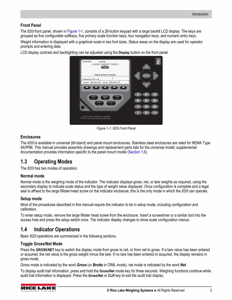
Front PanelThe 820i front panel, shown in Figure 1-1, consists of a 28-button keypad with a large backlit LCD display. The keys are grouped as five configurable softkeys, five primary scale function keys, four navigation keys, and numeric entry keys.Weight information is displayed with a graphical scale in two font sizes. Status areas on the display are used for operator prompts and entering data. LCD display contrast and backlighting can be adjusted using the Display button on the front panel.
Figure 1-1. 820i Front Panel
EnclosuresThe 820i is available in universal (tilt-stand) and panel mount enclosures. Stainless steel enclosures are rated for NEMA Type 4X/IP66. This manual provides assembly drawings and replacement parts lists for the universal model; supplemental documentation provides information specific to the panel mount model (Section 1.6).
1.3 Operating ModesThe 820i has two modes of operation.
Normal modeNormal mode is the weighing mode of the indicator. The indicator displays gross, net, or tare weights as required, using the secondary display to indicate scale status and the type of weight value displayed. Once configuration is complete and a legal seal is affixed to the large fillister-head screw on the indicator enclosure, this is the only mode in which the 820i can operate.
Setup modeMost of the procedures described in this manual require the indicator to be in setup mode, including configuration and calibration.To enter setup mode, remove the large fillister head screw from the enclosure. Insert a screwdriver or a similar tool into the access hole and press the setup switch once. The indicator display changes to show scale configuration menus.
1.4 Indicator OperationsBasic 820i operations are summarized in the following sections.
Toggle Gross/Net ModePress the GROSS/NET key to switch the display mode from gross to net, or from net to gross. If a tare value has been entered or acquired, the net value is the gross weight minus the tare. If no tare has been entered or acquired, the display remains in gross mode.Gross mode is indicated by the word Gross (or Brutto in OIML mode); net mode is indicated by the word Net.To display audit trail information, press and hold the Gross/Net mode key for three seconds. Weighing functions continue while audit trail information is displayed. Press the Gross/Net or CLR key to exit the audit trail display.
Display
05/28/2006 12:57PM
Accept
CONTRAST PFORMT FEATURE
0
Adjust Screen Contrast
Default Backlite On
Contrast (0-127) =>
Backlite Off

820i Programmable HMI Indicator/Controller
4 Visit our website www.RiceLake.com
Toggle UnitsPress the UNITS key to switch between primary, secondary, and tertiary units.
Zero Scale1. In gross mode, remove all weight from the scale and wait for the standstill annunciator ( ).2. Press the ZERO key. The center of zero ( ) annunciator lights to indicate the scale is zeroed.
Acquire Tare1. Place container on scale and wait for the standstill annunciator ( ).2. Press the TARE key to acquire the tare weight of the container. 3. Display shifts to net weight and shows the word Net on the display.
Remove Stored Tare Value1. Remove all weight from the scale and wait for the standstill annunciator ( ).2. Press the TARE key (or, in OIML mode, the ZERO key). Display shifts to gross weight and shows the word Gross.
Print Ticket1. Wait for the standstill annunciator ( ).2. Press the PRINT key to send data to the serial port.
Accumulator FunctionsThe accumulator must be enabled before use in either normal mode or setpoint operations. Once enabled, weight (net weight if a tare is in the system) is accumulated whenever a print operation is performed using the PRINT key, digital input, or serial command. The scale must return to zero (net zero if a tare is in the system) before the next accumulation. The Display Accum softkey can be configured to display the current accumulator value. Printing while the accumulator is displayed, or when the setpoint PSHACCUM function is active, uses the ACCFMT print format (see Section 6.0).Press the CLEAR key twice to clear the accumulator.
0
Introduction
© Rice Lake Weighing Systems ● All Rights Reserved 5
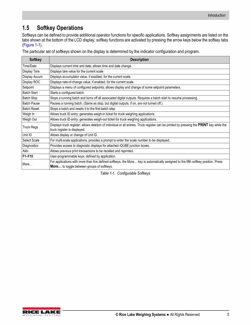
1.5 Softkey OperationsSoftkeys can be defined to provide additional operator functions for specific applications. Softkey assignments are listed on the tabs shown at the bottom of the LCD display; softkey functions are activated by pressing the arrow keys below the softkey tabs (Figure 1-1).The particular set of softkeys shown on the display is determined by the indicator configuration and program.
Softkey DescriptionTime/Date Displays current time and date; allows time and date change.Display Tare Displays tare value for the current scaleDisplay Accum Displays accumulator value, if enabled, for the current scale.Display ROC Displays rate-of-change value, if enabled, for the current scale.Setpoint Displays a menu of configured setpoints; allows display and change of some setpoint parameters.Batch Start Starts a configured batch.Batch Stop Stops a running batch and turns off all associated digital outputs. Requires a batch start to resume processing.Batch Pause Pauses a running batch. (Same as stop, but digital outputs, if on, are not turned off.)Batch Reset Stops a batch and resets it to the first batch step.Weigh In Allows truck ID entry; generates weigh-in ticket for truck weighing applications.Weigh Out Allows truck ID entry; generates weigh-out ticket for truck weighing applications.
Truck Regs Displays truck register; allows deletion of individual or all entries. Truck register can be printed by pressing the PRINT key while the truck register is displayed.
Unit ID Allows display or change of Unit ID.Select Scale For multi-scale applications, provides a prompt to enter the scale number to be displayed.Diagnostics Provides access to diagnostic displays for attached iQUBE junction boxes.Alibi Allows previous print transactions to be recalled and reprinted.F1–F10 User-programmable keys; defined by application.
More… For applications with more than five defined softkeys, the More… key is automatically assigned to the fifth softkey position. Press More… to toggle between groups of softkeys.
Table 1-1. Configurable Softkeys
820i Programmable HMI Indicator/Controller
6 Visit our website www.RiceLake.com
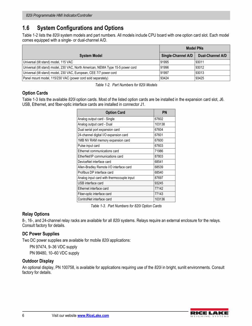
1.6 System Configurations and OptionsTable 1-2 lists the 820i system models and part numbers. All models include CPU board with one option card slot. Each model comes equipped with a single- or dual-channel A/D.
Option CardsTable 1-3 lists the available 820i option cards. Most of the listed option cards are be installed in the expansion card slot, J6. USB, Ethernet, and fiber-optic interface cards are installed in connector J1.
Relay Options8-, 16-, and 24-channel relay racks are available for all 820i systems. Relays require an external enclosure for the relays. Consult factory for details.
DC Power SuppliesTwo DC power supplies are available for mobile 820i applications:
PN 97474, 9–36 VDC supplyPN 99480, 10–60 VDC supply
Outdoor DisplayAn optional display, PN 100758, is available for applications requiring use of the 820i in bright, sunlit environments. Consult factory for details.
System Model
Model PNs
Single-Channel A/D Dual-Channel A/DUniversal (tilt stand) model, 115 VAC 91995 93011Universal (tilt stand) model, 230 VAC, North American, NEMA Type 15-5 power cord 91996 93012Universal (tilt stand) model, 230 VAC, European, CEE 7/7 power cord 91997 93013Panel mount model, 115/230 VAC (power cord sold separately) 93424 93425
Table 1-2. Part Numbers for 820i Models
Option Card PNAnalog output card - Single 67602Analog output card - Dual 103138Dual serial port expansion card 6760424-channel digital I/O expansion card 676011MB NV RAM memory expansion card 67600Pulse input card 67603Ethernet communications card 71986EtherNet/IP communications card 87803DeviceNet interface card 68541Allen-Bradley Remote I/O interface card 68539Profibus DP interface card 68540Analog input card with thermocouple input 87697USB interface card 93245Ethernet interface card 77142Fiber-optic interface card 77143ControlNet interface card 103136
Table 1-3. Part Numbers for 820i Option Cards
Introduction
© Rice Lake Weighing Systems ● All Rights Reserved 7
1.7 Summary of ChangesChanges to recent editions of this manual are listed below:
Version 1.05• Added TOKENS parameters to the SERIAL menu (see Section 3.2.2).
Version 1.04• Added new EDP command SF#n. See Section 9.1.5 for more information.• Added <AN> print token for alibi numbering. See Section 6.1 on page 52 for more information.• Added front panel token selections for streaming. See Figure 3-9 for more information.• Changed default PFORMAT port setting to the new NONE selection. See Figure 3-15 on page 40 for setting.
Version 1.02• Support for local/remote indicator configurations provides function equivalent to a legal-for-trade remote display with
keypad for truck scale and similar applications. See Section 10.4 for more information.• The description for setting rate of change (ROC) parameters has been changed. See Table 3-3 on page 25 for details.• New values have been added to the STREAM parameter on the SERIAL menu to allow streaming of keypad events to
another indicator (4KEYS, KEYPAD) and, for the local/remote function, to send the complete display image (DISPLAY). See Section 3.2.2 for more information.
• New IMAGE parameter on the FEATURE menu allows inversion of the display image (blue-on-white or white-on-blue) for support of the outdoor display option. See Section 3.2.3 for more information.
• Display and printing of audit trail information is described in Section 10.10.
820i Programmable HMI Indicator/Controller
8 Visit our website www.RiceLake.com
2.0 InstallationThis section describes procedures for connecting load cell, digital I/O, and serial communications cables to the 820i indicator. Assembly drawings and replacement parts lists for the universal model are included for the service technician. See Section 10.11 for dimension drawings.
Use a wrist strap for grounding and to protect components from electrostatic discharge (ESD) when working inside the indicator enclosure.This unit uses double pole/neutral fusing which could create an electric shock hazard. Procedures requiring work inside the indicator must be performed by qualified service personnel only.The supply cord serves as the power disconnect for the 820i. The power outlet supplying the indicator must be installed near the unit and be easily accessible.
2.1 Unpacking and AssemblyImmediately after unpacking, visually inspect the 820i to ensure all components are included and undamaged. The shipping carton should contain the indicator, this manual, and a parts kit. If any parts were damaged in shipment, notify Rice Lake Weighing Systems and the shipper immediately.See Section 2.9 for parts kit contents.
2.2 Enclosure DisassemblyThe indicator enclosure must be opened to install option cards and to connect cables for installed option cards.
The 820i has no on/off switch. Before opening the unit, ensure the power cord is disconnected from the power outlet.
1. Ensure power to the indicator is disconnected.2. Place the indicator face-down on an anti static work mat. 3. Remove the screws that hold the backplate to the enclosure body.4. Lift the backplate away from the enclosure and set it aside.
CAUTION
WARNING

Installation
© Rice Lake Weighing Systems ● All Rights Reserved 9
2.3 Cable ConnectionsThe universal model of the 820i provides six cord grips for cabling into the indicator: one for the power cord, five to accommodate other cabling. Install plugs in all unused cord grips to prevent moisture from entering the enclosure.
2.3.1 Cable GroundingExcept for the power cord, all cables routed through the cord grips should be grounded against the indicator enclosure. To ground shielded cables:
1. Use the lockwashers, clamps, and kep nuts provided in the parts kit to secure grounding clamps to the enclosure studs near the cord grips. Install clamps only for cord grips that will be used. Do not tighten nuts.
2. Route cables through cord grips and clamps to determine cable length required to reach cable connectors. 3. Mark cables to remove insulation and shield.
• Foil shielded cables – strip insulation and foil from cable 1/2 inch (13 mm) past the grounding clamp (see Figure 2-1). Fold the foil shield back onto the cable where it passes through the clamp. Ensure silver (conductive) side of foil is outward to contact with the grounding clamp.
• Braided shielded cables – strip cable insulation and shield to just past the clamp. Strip another 1/2 inch (15 mm) of insulation to expose the shield where it passes through the clamp (see Figure 2-1).
• Load cell cables – cut the shield wire just past the grounding clamp. Shield wire function is provided by contact between the cable shield and the grounding clamp.
4. Route stripped cables through cord grips and clamps. Ensure shields contact clamps as shown in Figure 2-1. 5. Tighten grounding clamp nuts.6. Finish installation using cable ties to secure cables inside of indicator enclosure.
Cor d grip
Insulated cable
Foil (silver side out) Gr ounding clamp
Shield wir e (cut)
Length of foil before folding back on cable insulation
Cut insulation here for foil-shielded cables
Braid
Cut insulation here for braided cables
NOTE: Install lockwashers first, against enclosure, under grounding clamp
Figure 2-1. Grounding Cables
820i Programmable HMI Indicator/Controller
10 Visit our website www.RiceLake.com
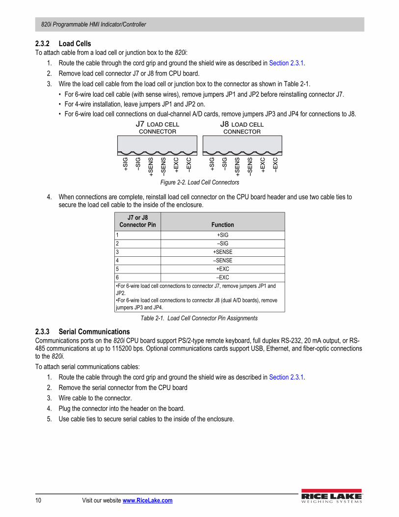
2.3.2 Load CellsTo attach cable from a load cell or junction box to the 820i:
1. Route the cable through the cord grip and ground the shield wire as described in Section 2.3.1. 2. Remove load cell connector J7 or J8 from CPU board. 3. Wire the load cell cable from the load cell or junction box to the connector as shown in Table 2-1.
• For 6-wire load cell cable (with sense wires), remove jumpers JP1 and JP2 before reinstalling connector J7.• For 4-wire installation, leave jumpers JP1 and JP2 on. • For 6-wire load cell connections on dual-channel A/D cards, remove jumpers JP3 and JP4 for connections to J8.
Figure 2-2. Load Cell Connectors
4. When connections are complete, reinstall load cell connector on the CPU board header and use two cable ties to secure the load cell cable to the inside of the enclosure.
2.3.3 Serial CommunicationsCommunications ports on the 820i CPU board support PS/2-type remote keyboard, full duplex RS-232, 20 mA output, or RS-485 communications at up to 115200 bps. Optional communications cards support USB, Ethernet, and fiber-optic connections to the 820i.To attach serial communications cables:
1. Route the cable through the cord grip and ground the shield wire as described in Section 2.3.1.2. Remove the serial connector from the CPU board 3. Wire cable to the connector. 4. Plug the connector into the header on the board. 5. Use cable ties to secure serial cables to the inside of the enclosure.
J7 or J8Connector Pin Function
1 +SIG2 –SIG3 +SENSE4 –SENSE5 +EXC6 –EXC•For 6-wire load cell connections to connector J7, remove jumpers JP1 and JP2. •For 6-wire load cell connections to connector J8 (dual A/D boards), remove jumpers JP3 and JP4.
Table 2-1. Load Cell Connector Pin Assignments
J7 LOAD CELLCONNECTOR
J8 LOAD CELLCONNECTOR
+S
IG
–SIG
+S
EN
S
–SE
NS
+E
XC
–EX
C
+S
IG
–SIG
+S
EN
S
–SE
NS
+E
XC
–EX
C
Installation
© Rice Lake Weighing Systems ● All Rights Reserved 11
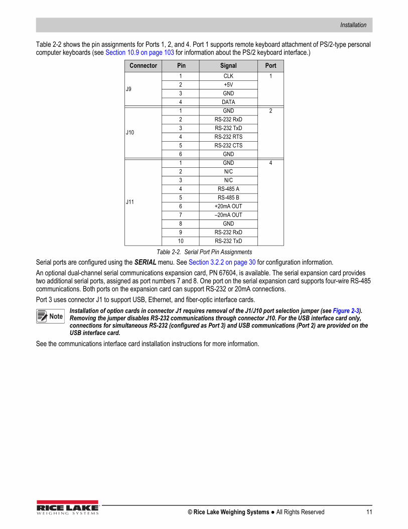
Table 2-2 shows the pin assignments for Ports 1, 2, and 4. Port 1 supports remote keyboard attachment of PS/2-type personal computer keyboards (see Section 10.9 on page 103 for information about the PS/2 keyboard interface.)
Serial ports are configured using the SERIAL menu. See Section 3.2.2 on page 30 for configuration information.An optional dual-channel serial communications expansion card, PN 67604, is available. The serial expansion card provides two additional serial ports, assigned as port numbers 7 and 8. One port on the serial expansion card supports four-wire RS-485 communications. Both ports on the expansion card can support RS-232 or 20mA connections.Port 3 uses connector J1 to support USB, Ethernet, and fiber-optic interface cards.
Installation of option cards in connector J1 requires removal of the J1/J10 port selection jumper (see Figure 2-3). Removing the jumper disables RS-232 communications through connector J10. For the USB interface card only, connections for simultaneous RS-232 (configured as Port 3) and USB communications (Port 2) are provided on the USB interface card.
See the communications interface card installation instructions for more information.
Connector Pin Signal Port
J9
1 CLK 12 +5V3 GND4 DATA
J10
1 GND 22 RS-232 RxD3 RS-232 TxD4 RS-232 RTS5 RS-232 CTS6 GND
J11
1 GND 42 N/C3 N/C4 RS-485 A5 RS-485 B6 +20mA OUT7 –20mA OUT8 GND9 RS-232 RxD
10 RS-232 TxD
Table 2-2. Serial Port Pin Assignments
Note
820i Programmable HMI Indicator/Controller
12 Visit our website www.RiceLake.com
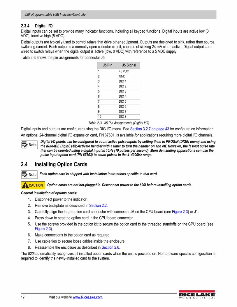
2.3.4 Digital I/ODigital inputs can be set to provide many indicator functions, including all keypad functions. Digital inputs are active low (0 VDC), inactive high (5 VDC).Digital outputs are typically used to control relays that drive other equipment. Outputs are designed to sink, rather than source, switching current. Each output is a normally open collector circuit, capable of sinking 24 mA when active. Digital outputs are wired to switch relays when the digital output is active (low, 0 VDC) with reference to a 5 VDC supply. Table 2-3 shows the pin assignments for connector J5.
Digital inputs and outputs are configured using the DIG I/O menu. See Section 3.2.7 on page 43 for configuration information.An optional 24-channel digital I/O expansion card, PN 67601, is available for applications requiring more digital I/O channels.
Digital I/O points can be configured to count active pulse inputs by setting them to PROGIN (DIGIN menu) and using the iRite-IDE DigInSsBbActivate handler with a timer to turn the handler on and off. However, the fastest pulse rate that can be counted using a digital input is 10Hz (10 pulses per second). More demanding applications can use the pulse input option card (PN 67603) to count pulses in the 4–4000Hz range.
2.4 Installing Option Cards Each option card is shipped with installation instructions specific to that card.
Option cards are not hot-pluggable. Disconnect power to the 820i before installing option cards.
General installation of options cards:1. Disconnect power to the indicator. 2. Remove backplate as described in Section 2.2.3. Carefully align the large option card connector with connector J6 on the CPU board (see Figure 2-3) or J1. 4. Press down to seat the option card in the CPU board connector.5. Use the screws provided in the option kit to secure the option card to the threaded standoffs on the CPU board (see
Figure 2-3).6. Make connections to the option card as required. 7. Use cable ties to secure loose cables inside the enclosure. 8. Reassemble the enclosure as described in Section 2.6.
The 820i automatically recognizes all installed option cards when the unit is powered on. No hardware-specific configuration is required to identify the newly-installed card to the system.
J5 Pin J5 Signal1 +5 VDC2 GND3 DIO 14 DIO 25 DIO 36 DIO 47 DIO 58 DIO 69 DIO 710 DIO 8
Table 2-3. J5 Pin Assignments (Digital I/O)
Note
Note
CAUTION
Installation
© Rice Lake Weighing Systems ● All Rights Reserved 13
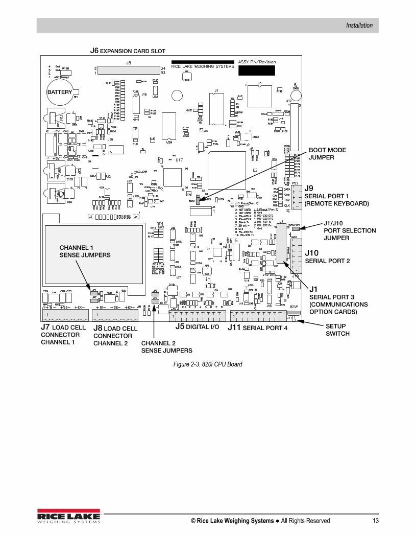
Figure 2-3. 820i CPU Board
J7 LOAD CELLCONNECTORCHANNEL 1
J8 LOAD CELLCONNECTORCHANNEL 2
J5 DIGITAL I/O J11 SERIAL PORT 4
J10SERIAL PORT 2
J1SERIAL PORT 3(COMMUNICATIONS OPTION CARDS)
J9SERIAL PORT 1(REMOTE KEYBOARD)
J6 EXPANSION CARD SLOT
SETUPSWITCH
BATTERY
J1/J10PORT SELECTION JUMPER
4
CHANNEL 1SENSE JUMPERS
CHANNEL 2SENSE JUMPERS
BOOT MODEJUMPER
820i Programmable HMI Indicator/Controller
14 Visit our website www.RiceLake.com
2.5 Slot AssignmentsTable 2-4 lists the slot numbers, CPU board connectors, and configuration assignments made for both onboard and expansion card functions in the 820i. See Figure 2-3 for connector locations.
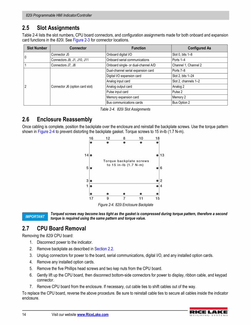
2.6 Enclosure ReassemblyOnce cabling is complete, position the backplate over the enclosure and reinstall the backplate screws. Use the torque pattern shown in Figure 2-4 to prevent distorting the backplate gasket. Torque screws to 15 in-lb (1.7 N-m).
Figure 2-4. 820i Enclosure Backplate
Torqued screws may become less tight as the gasket is compressed during torque pattern, therefore a second torque is required using the same pattern and torque value.
2.7 CPU Board RemovalRemoving the 820i CPU board:
1. Disconnect power to the indicator. 2. Remove backplate as described in Section 2.2.3. Unplug connectors for power to the board, serial communications, digital I/O, and any installed option cards.4. Remove any installed option cards.5. Remove the five Phillips head screws and two kep nuts from the CPU board.6. Gently lift up the CPU board, then disconnect bottom-side connectors for power to display, ribbon cable, and keypad
connector.7. Remove CPU board from the enclosure. If necessary, cut cable ties to shift cables out of the way.
To replace the CPU board, reverse the above procedure. Be sure to reinstall cable ties to secure all cables inside the indicator enclosure.
Slot Number Connector Function Configured As
0Connector J5 Onboard digital I/O Slot 0, bits 1–8Connectors J9, J1, J10, J11 Onboard serial communications Ports 1–4
1 Connectors J7, J8 Onboard single- or dual-channel A/D Channel 1, Channel 2
2 Connector J6 (option card slot)
Dual-channel serial expansion card Ports 7–8Digital I/O expansion card Slot 2, bits 1–24Analog input card Slot 2, channels 1–2Analog output card Analog 2Pulse input card Pulse 2Memory expansion card Memory 2Bus communications cards Bus Option 2
Table 2-4. 820i Slot Assignments
13
5
14
17
16 12
9
8
7
10
11
18
15
42
6
13
Torque backplate screwsto 15 in- lb (1.7 N-m)
IMPORTANT
Installation
© Rice Lake Weighing Systems ● All Rights Reserved 15
2.8 Battery ReplacementThe lithium battery on the CPU board maintains the real-time clock and protects data stored in the system RAM when the indicator is not connected to AC power. Data protected includes time and date, truck and tare memory, onboard database information, and setpoint configuration. Use Revolution to store a copy of the indicator configuration on a PC before attempting battery replacement. If data is lost, the indicator configuration can be restored from the PC.A low battery warning on the LCD display will display when battery needs to be replaced. Battery voltage on the CPU board and on installed memory option cards should be checked periodically. If battery voltage is to 2.2 VDC or less, replace the battery. Life expectancy of the battery is ten years.
Replacement ProcedureReplace the battery while in weigh mode and AC power applied. Use care not to bend the battery retaining spring.If the battery must be replaced with power removed, immediately after restoring power:
1. Place indicator in setup mode.2. Navigate to the Version menu and press the Reset Config softkey. If connected using Revolution, configuration can be
reset by using monitor mode to enter the RESETCONFIGURATION command followed by the RS command.See Figure 2-3 for CPU board battery location and orientation (positive side up).
Risk of explosion if battery is replaced with incorrect type. Dispose of batteries per manufacturer instruction.
2.9 Parts Kit ContentsTable 2-5 lists the parts kit contents for the universal model of the 820i.
2.10 Universal Replacement PartsFor replacement parts information for the panel mount enclosures, see the 820i Panel Mount Installation Instructions, PN 95304.
Part No. Description Qty14626 Kep nuts, 8-32NC 314862 Machine screws, 8-32NC x 3/8 1275062 Sealing washers 1415133 Lock washers, No. 8, Type A 530623 Machine screws, 8-32NC x 7/16 215631 Cable ties 815665 Reducing gland for 1/2 NPT cord grip 1
15887 6-position screw terminal for load cell connection (1–single A/D, 2–dual A/D)
19538 Cord grip plugs 494422 Capacity label 153075 Cable shield ground clamps 576514 6-position screw terminal for J10 176513 4-position screw terminal for J9 171344 10-position screw terminals for J5 and J11 242149 Rubber feet for tilt stand 4103988 Nylon washers for tilt stand 2103610 Knobs for tilt stand 277925 Indicator/HMI Software Tool Kit CD 1
Table 2-5. Parts Kit Contents (PN 94139)
CAUTION
Note
820i Programmable HMI Indicator/Controller
16 Visit our website www.RiceLake.com
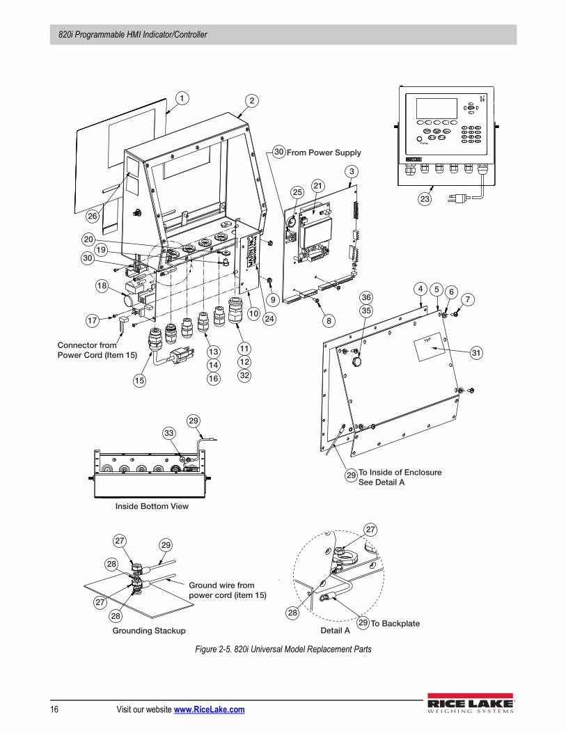
Figure 2-5. 820i Universal Model Replacement Parts
1 2
2521
3
23
94
8
5 67
35
36
31
2410
11
12
32
13
14
1615
33
29
17
18
3019
20
26
27
2829 To Backplate
29 To Inside of EnclosureSee Detail A
Connector fromPower Cord (Item 15)
30 From Power Supply
28
27 29
27
28
Ground wire frompower cord (item 15)
Grounding Stackup Detail A
Inside Bottom View
Installation
© Rice Lake Weighing Systems ● All Rights Reserved 17
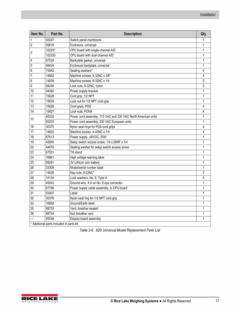
Item No. Part No. Description Qty1 93247 Switch panel membrane 12 93618 Enclosure, universal 1
3102331 CPU board with single-channel A/D 1102333 CPU board with dual-channel A/D 1
4 67532 Backplate gasket, universal 15 68424 Enclosure backplate, universal 16 75062 Sealing washers* 47 14862 Machine screws, 8-32NC x 3/8* 48 14839 Machine screws, 6-32NC x 1/4 39 58248 Lock nuts, 6-32NC, nylon 210 94392 Power supply bracket 111 15628 Cord grip, 1/2 NPT 112 15630 Lock nut for 1/2 NPT cord grip 113 15626 Cord grips, PG9 414 15627 Lock nuts, PCN9 4
1585202 Power cord assembly, 115 VAC and 230 VAC North American units 185203 Power cord assembly, 230 VAC European units 1
16 30375 Nylon seal rings for PG9 cord grips 417 14822 Machine screws, 4-40NC x 1/4 418 67613 Power supply, ±6VDC, 25W 119 42640 Setup switch access screw, 1/4 x 28NF x 1/4 120 44676 Sealing washer for setup switch access screw 123 67531 Tilt stand 124 16861 High voltage warning label 125 69291 3V Lithium coin battery 126 53308 Model/serial number label 127 14626 Kep nuts, 8-32NC* 328 15134 Lock washers, No. 8, Type A 329 45043 Ground wire, 4 in w/ No. 8 eye connector 130 67796 Power supply cable assembly, to CPU board 131 53307 Label 132 30376 Nylon seal ring for 1/2 NPT cord grip 133 16892 Ground/Earth label 135 88733 Vent, breather sealed 136 88734 Nut, breather vent 1— 93246 Display board assembly 1* Additional parts included in parts kit.
Table 2-6. 820i Universal Model Replacement Parts List
820i Programmable HMI Indicator/Controller
18 Visit our website www.RiceLake.com
3.0 ConfigurationTo configure the 820i indicator, the indicator must be placed in setup mode. The setup switch is accessed by removing the large fillister head screw on the bottom of the enclosure. Switch position is changed by inserting a screwdriver into the access hole and pressing the switch.When the indicator is placed in setup mode, a series of menus is shown across the top of the display, along with the words Scale Configuration. The SCALES menu is highlighted as the first used to configure the indicator. Detailed descriptions of these menus are provided in Section 3.2. When configuration is complete, press the Exit or Save and Exit softkey to exit setup mode, then replace the setup switch access screw.
• The Exit softkey exits setup mode without saving parameter changes to NV RAM. Changes made to the configuration remain in the system until indicator power is cycled.
• Save and Exit writes all parameter changes to NV RAM before returning to normal mode.
3.1 Configuration MethodsThe 820i indicator can be configured by using the front panel keys to navigate through a series of configuration menus or by sending commands or configuration data to an indicator serial port. Configuration using the menus is described in Section 3.1.3.Configuration using the serial port can be accomplished using either the serial command set described in Section 9.0 on page 80 or the Revolution® configuration utility.
Some configuration parameters, such as those used to configure the 820i display, cannot be accessed through the configuration menus. Revolution provides the most complete and efficient configuration interface for the 820i.
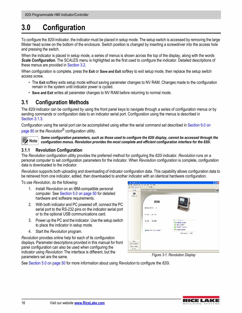
3.1.1 Revolution ConfigurationThe Revolution configuration utility provides the preferred method for configuring the 820i indicator. Revolution runs on a personal computer to set configuration parameters for the indicator. When Revolution configuration is complete, configuration data is downloaded to the indicator.Revolution supports both uploading and downloading of indicator configuration data. This capability allows configuration data to be retrieved from one indicator, edited, then downloaded to another indicator with an identical hardware configuration.To use Revolution, do the following:
1. Install Revolution on an IBM-compatible personal computer. See Section 5.0 on page 50 for detailed hardware and software requirements.
2. With both indicator and PC powered off, connect the PC serial port to the RS-232 pins on the indicator serial port or to the optional USB communications card.
3. Power up the PC and the indicator. Use the setup switch to place the indicator in setup mode.
4. Start the Revolution program. Revolution provides online help for each of its configuration displays. Parameter descriptions provided in this manual for front panel configuration can also be used when configuring the indicator using Revolution: The interface is different, but the parameters set are the same.See Section 5.0 on page 50 for more information about using Revolution to configure the 820i.
Note
Figure 3-1. Revolution Display
Configuration
© Rice Lake Weighing Systems ● All Rights Reserved 19
3.1.2 Serial Command ConfigurationThe serial command set can be used to configure the 820i indicator using either a personal computer, terminal, or remote keyboard. Like Revolution, serial command configuration sends commands to the indicator serial port; unlike Revolution, serial commands can be sent using any external device capable of sending ASCII characters over a serial connection.Serial commands duplicate the functions available using the indicator front panel and provide some functions not otherwise available. Serial commands can be used to simulate pressing front panel keys, to configure the indicator, or to dump lists of parameter settings. See Section 9.0 on page 80 for more information about using the serial command set.
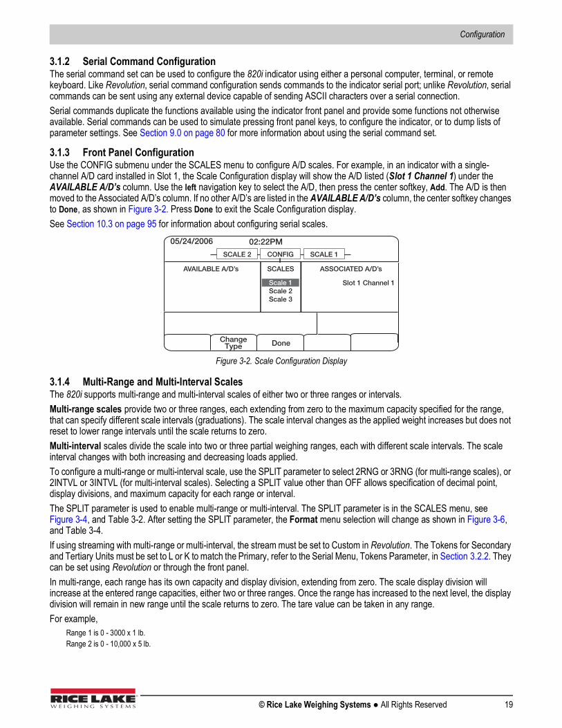
3.1.3 Front Panel ConfigurationUse the CONFIG submenu under the SCALES menu to configure A/D scales. For example, in an indicator with a single-channel A/D card installed in Slot 1, the Scale Configuration display will show the A/D listed (Slot 1 Channel 1) under the AVAILABLE A/D’s column. Use the left navigation key to select the A/D, then press the center softkey, Add. The A/D is then moved to the Associated A/D’s column. If no other A/D’s are listed in the AVAILABLE A/D’s column, the center softkey changes to Done, as shown in Figure 3-2. Press Done to exit the Scale Configuration display.See Section 10.3 on page 95 for information about configuring serial scales.
Figure 3-2. Scale Configuration Display
3.1.4 Multi-Range and Multi-Interval ScalesThe 820i supports multi-range and multi-interval scales of either two or three ranges or intervals. Multi-range scales provide two or three ranges, each extending from zero to the maximum capacity specified for the range, that can specify different scale intervals (graduations). The scale interval changes as the applied weight increases but does not reset to lower range intervals until the scale returns to zero.Multi-interval scales divide the scale into two or three partial weighing ranges, each with different scale intervals. The scale interval changes with both increasing and decreasing loads applied.To configure a multi-range or multi-interval scale, use the SPLIT parameter to select 2RNG or 3RNG (for multi-range scales), or 2INTVL or 3INTVL (for multi-interval scales). Selecting a SPLIT value other than OFF allows specification of decimal point, display divisions, and maximum capacity for each range or interval.The SPLIT parameter is used to enable multi-range or multi-interval. The SPLIT parameter is in the SCALES menu, see Figure 3-4, and Table 3-2. After setting the SPLIT parameter, the Format menu selection will change as shown in Figure 3-6, and Table 3-4.If using streaming with multi-range or multi-interval, the stream must be set to Custom in Revolution. The Tokens for Secondary and Tertiary Units must be set to L or K to match the Primary, refer to the Serial Menu, Tokens Parameter, in Section 3.2.2. They can be set using Revolution or through the front panel.In multi-range, each range has its own capacity and display division, extending from zero. The scale display division will increase at the entered range capacities, either two or three ranges. Once the range has increased to the next level, the display division will remain in new range until the scale returns to zero. The tare value can be taken in any range.For example,
Range 1 is 0 - 3000 x 1 lb.Range 2 is 0 - 10,000 x 5 lb.
05/24/2006 02:22PM
ChangeType Done
CONFIG SCALE 1SCALE 2
Scale 1Scale 2Scale 3
SCALES ASSOCIATED A/D’sAVAILABLE A/D’s
Slot 1 Channel 1
820i Programmable HMI Indicator/Controller
20 Visit our website www.RiceLake.com
In multi-interval, the scale has one capacity, which is segmented into weighing intervals, either two or three intervals, each with different display division sizes. As the weight value exceeds an interval or set interval, the display division will increase, as the weight falls below an interval or set interval, the display division will decrease. The tare can only be taken in the first interval.For example,
Range 1 is 0-30 x 0.01 lb.Range 2 is 30 - 60 x 0.02 lbs.
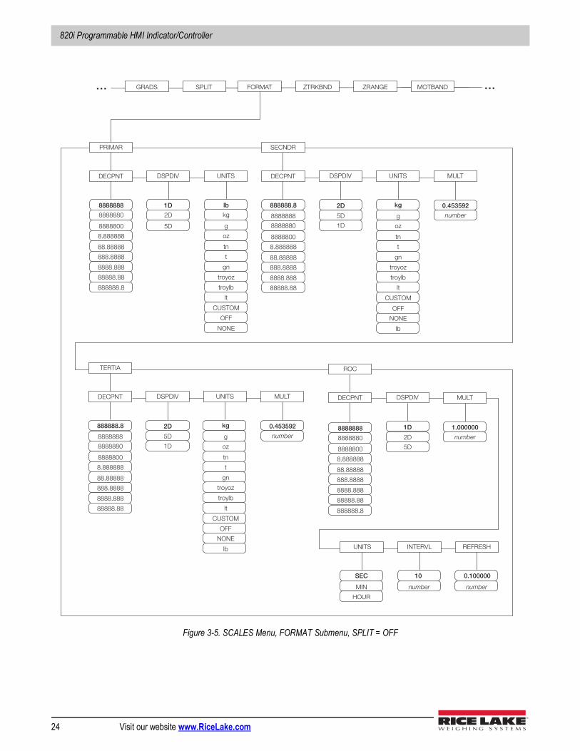
3.1.5 Total Scale ConfigurationThe output of A/D scales, serial scales, or iQUBE systems can be configured to function as a total scale. Once configured and calibrated, the total scale can be used as a source for other system functions, including streaming, setpoints, print formatting, and analog output.To set up a total scale from the indicator front panel, use the scale configuration display (see Figure 3-2) to select the A/D scales or iQUBE systems to configure as a total scale. (Use the Change Type softkey to show available A/D scales or iQUBE systems; use the right navigation key to select the total scale sources.) In Revolution, assign the total scale to an unused position then select source scales from the existing A/D scales or iQUBE systems.The FORMAT configuration of the total scale (see Figure 3-5 on page 24) should match that of the source scales. However, the value specified for the total scale GRADS parameter should be specified as the sum of the GRADS values for the source scales. For example: if SCALE 1 is set to GRADS=10000, SCALE 2 to GRADS=5000, SCALE 3 (the total scale) should be set to 15000 grads.The total scale will show an overrange indication if the maximum capacity of any source scale is exceeded, and show dashes if any source scale reads a negative value. Source scales will respond to Tare and Zero operations performed on the total scale.
Total scale function is not supported for multi-range or multi-interval scales at this time.
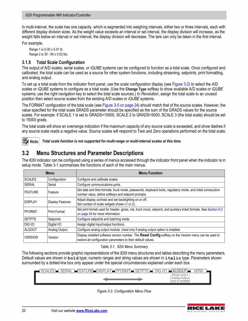
3.2 Menu Structures and Parameter DescriptionsThe 820i indicator can be configured using a series of menus accessed through the indicator front panel when the indicator is in setup mode. Table 3-1 summarizes the functions of each of the main menus.
The following sections provide graphic representations of the 820i menu structures and tables describing the menu parameters. Default values are shown in bold type; numeric ranges and string values are shown in italic type. Parameters shown surrounded by a dotted-line box only appear under the special circumstances explained under each box.
Figure 3-3. Configuration Menu Flow
Menu Menu FunctionSCALES Configuration Configure and calibrate scales.SERIAL Serial Configure communications ports.
FEATURE Feature Set date and time formats, truck mode, passwords, keyboard locks, regulatory mode, and initial consecutive number value, define softkeys and setpoint prompts.
DISPLAY Display Features Adjust display contrast and set backlighting on or off. Set number of scale widgets shown (1 or 2).
PFORMT Print Format Set print format used for header, gross, net, truck in/out, setpoint, and auxiliary ticket formats. See Section 6.0 on page 54 for more information.
SETPTS Setpoints Configure setpoints and batching mode.DIG I/O Digital I/O Assign digital input/output functions.ALGOUT Analog Output Configure analog output module. Used only if analog output option is installed.
VERSION Version Display installed software version number. The Reset Config softkey on the Version menu can be used to restore all configuration parameters to their default values.
Table 3-1. 820i Menu Summary
Note
SCALES FEATURE PFORMT SETPTS DIG I/O ALGOUT VERSShown only ifAnalog Outputcard is installed
DISPLAYSERIAL
Configuration
© Rice Lake Weighing Systems ● All Rights Reserved 21
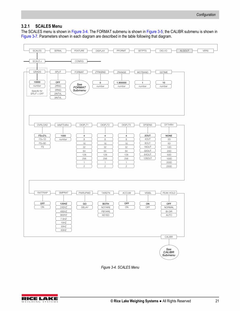
3.2.1 SCALES MenuThe SCALES menu is shown in Figure 3-4. The FORMAT submenu is shown in Figure 3-5; the CALIBR submenu is shown in Figure 3-7. Parameters shown in each diagram are described in the table following that diagram.
Figure 3-4. SCALES Menu
SCALES SERIAL FEATURE PFORMT SETPTS DIG I/O ALGOUT VERS
SCALE x
GRADS ZRANGE MOTBAND
OVRLOAD
SSTIME
DIGFLT1 DIGFLT2
10000
number
ZTRKBND
0
number
1.900000
number
1
number
FS+2%
FS+9D
FS+1D
FS
number
10
64
128
4
16
8
32
256
DFSENS
RATTRAP
DFTHRH
PWRUPMD TAREFN
32OUT
64OUT
2OUT
8OUT
4OUT
16OUT
128OUT
20D
50D
250D
5D
2D
10D
100D
NONE
200D
OFF
ON
SMPRAT
7.5HZ
15HZ
120HZ
480HZ
240HZ
960HZ
30HZ
60HZ
GO
DELAY
BOTH
PBTARE
NOTARE
KEYED
See FORMAT Submenu
1
2
DIGFLT3
CONFIG
ACCUM
CALIBR
OFF
ON
VISIBL
ON
OFF
FORMAT
See CALIBR
Submenu
64
128
4
16
8
32
256
1
2
64
128
4
16
8
32
256
1
2
WMTTHRH
number
1000
SPLIT
PEAK HOLD
OFF
BI-DIR
NORMAL
AUTO
3INTVL
3RNG
2RNG
2INTVL
OFF
DISPLAY
Specify for SPLIT = OFF
820i Programmable HMI Indicator/Controller
22 Visit our website www.RiceLake.com
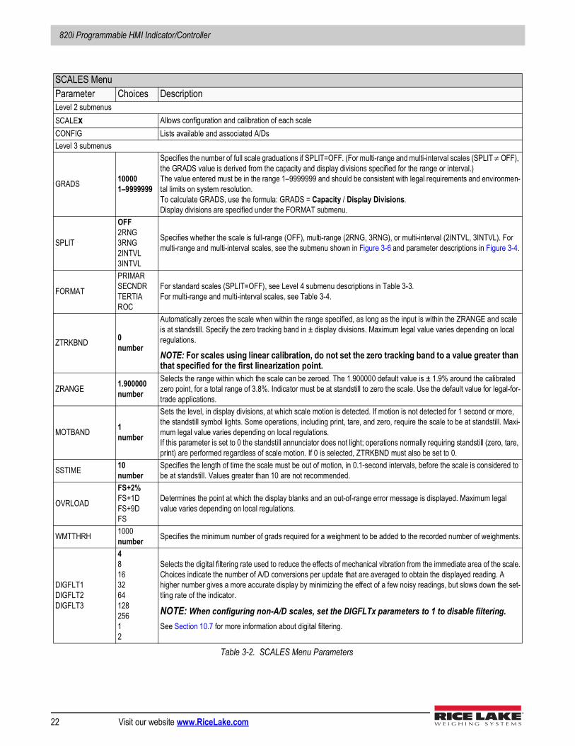
SCALES MenuParameter Choices DescriptionLevel 2 submenusSCALEx Allows configuration and calibration of each scaleCONFIG Lists available and associated A/DsLevel 3 submenus
GRADS 100001–9999999
Specifies the number of full scale graduations if SPLIT=OFF. (For multi-range and multi-interval scales (SPLIT OFF), the GRADS value is derived from the capacity and display divisions specified for the range or interval.)The value entered must be in the range 1–9999999 and should be consistent with legal requirements and environmen-tal limits on system resolution. To calculate GRADS, use the formula: GRADS = Capacity / Display Divisions.Display divisions are specified under the FORMAT submenu.
SPLIT
OFF2RNG3RNG2INTVL3INTVL
Specifies whether the scale is full-range (OFF), multi-range (2RNG, 3RNG), or multi-interval (2INTVL, 3INTVL). For multi-range and multi-interval scales, see the submenu shown in Figure 3-6 and parameter descriptions in Figure 3-4.
FORMAT
PRIMARSECNDRTERTIAROC
For standard scales (SPLIT=OFF), see Level 4 submenu descriptions in Table 3-3. For multi-range and multi-interval scales, see Table 3-4.
ZTRKBND 0number
Automatically zeroes the scale when within the range specified, as long as the input is within the ZRANGE and scale is at standstill. Specify the zero tracking band in ± display divisions. Maximum legal value varies depending on local regulations.
NOTE: For scales using linear calibration, do not set the zero tracking band to a value greater than that specified for the first linearization point.
ZRANGE 1.900000number
Selects the range within which the scale can be zeroed. The 1.900000 default value is ± 1.9% around the calibrated zero point, for a total range of 3.8%. Indicator must be at standstill to zero the scale. Use the default value for legal-for-trade applications.
MOTBAND 1number
Sets the level, in display divisions, at which scale motion is detected. If motion is not detected for 1 second or more, the standstill symbol lights. Some operations, including print, tare, and zero, require the scale to be at standstill. Maxi-mum legal value varies depending on local regulations.If this parameter is set to 0 the standstill annunciator does not light; operations normally requiring standstill (zero, tare, print) are performed regardless of scale motion. If 0 is selected, ZTRKBND must also be set to 0.
SSTIME 10number
Specifies the length of time the scale must be out of motion, in 0.1-second intervals, before the scale is considered to be at standstill. Values greater than 10 are not recommended.
OVRLOAD
FS+2%FS+1DFS+9DFS
Determines the point at which the display blanks and an out-of-range error message is displayed. Maximum legal value varies depending on local regulations.
WMTTHRH 1000number Specifies the minimum number of grads required for a weighment to be added to the recorded number of weighments.
DIGFLT1DIGFLT2DIGFLT3
4816326412825612
Selects the digital filtering rate used to reduce the effects of mechanical vibration from the immediate area of the scale.Choices indicate the number of A/D conversions per update that are averaged to obtain the displayed reading. A higher number gives a more accurate display by minimizing the effect of a few noisy readings, but slows down the set-tling rate of the indicator.
NOTE: When configuring non-A/D scales, set the DIGFLTx parameters to 1 to disable filtering.See Section 10.7 for more information about digital filtering.
Table 3-2. SCALES Menu Parameters
Configuration
© Rice Lake Weighing Systems ● All Rights Reserved 23
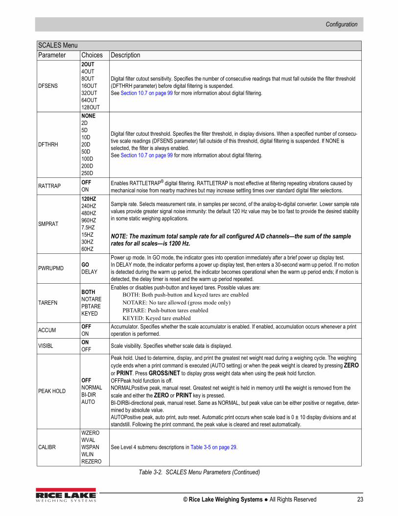
DFSENS
2OUT4OUT8OUT16OUT32OUT64OUT128OUT
Digital filter cutout sensitivity. Specifies the number of consecutive readings that must fall outside the filter threshold (DFTHRH parameter) before digital filtering is suspended.See Section 10.7 on page 99 for more information about digital filtering.
DFTHRH
NONE2D5D10D20D50D100D200D250D
Digital filter cutout threshold. Specifies the filter threshold, in display divisions. When a specified number of consecu-tive scale readings (DFSENS parameter) fall outside of this threshold, digital filtering is suspended. If NONE is selected, the filter is always enabled. See Section 10.7 on page 99 for more information about digital filtering.
RATTRAP OFFON
Enables RATTLETRAP® digital filtering. RATTLETRAP is most effective at filtering repeating vibrations caused by mechanical noise from nearby machines but may increase settling times over standard digital filter selections.
SMPRAT
120HZ240HZ480HZ960HZ7.5HZ15HZ30HZ60HZ
Sample rate. Selects measurement rate, in samples per second, of the analog-to-digital converter. Lower sample rate values provide greater signal noise immunity: the default 120 Hz value may be too fast to provide the desired stability in some static weighing applications.
NOTE: The maximum total sample rate for all configured A/D channels—the sum of the sample rates for all scales—is 1200 Hz.
PWRUPMD GODELAY
Power up mode. In GO mode, the indicator goes into operation immediately after a brief power up display test.In DELAY mode, the indicator performs a power up display test, then enters a 30-second warm up period. If no motion is detected during the warm up period, the indicator becomes operational when the warm up period ends; if motion is detected, the delay timer is reset and the warm up period repeated.
TAREFN
BOTHNOTAREPBTAREKEYED
Enables or disables push-button and keyed tares. Possible values are:BOTH: Both push-button and keyed tares are enabledNOTARE: No tare allowed (gross mode only)PBTARE: Push-button tares enabledKEYED: Keyed tare enabled
ACCUM OFFON
Accumulator. Specifies whether the scale accumulator is enabled. If enabled, accumulation occurs whenever a print operation is performed.
VISIBL ONOFF Scale visibility. Specifies whether scale data is displayed.
PEAK HOLD
OFFNORMALBI-DIRAUTO
Peak hold. Used to determine, display, and print the greatest net weight read during a weighing cycle. The weighing cycle ends when a print command is executed (AUTO setting) or when the peak weight is cleared by pressing ZERO or PRINT. Press GROSS/NET to display gross weight data when using the peak hold function.OFFPeak hold function is off.NORMALPositive peak, manual reset. Greatest net weight is held in memory until the weight is removed from the scale and either the ZERO or PRINT key is pressed.BI-DIRBi-directional peak, manual reset. Same as NORMAL, but peak value can be either positive or negative, deter-mined by absolute value.AUTOPositive peak, auto print, auto reset. Automatic print occurs when scale load is 0 ± 10 display divisions and at standstill. Following the print command, the peak value is cleared and reset automatically.
CALIBR
WZEROWVALWSPANWLINREZERO
See Level 4 submenu descriptions in Table 3-5 on page 29.
SCALES MenuParameter Choices Description
Table 3-2. SCALES Menu Parameters (Continued)
820i Programmable HMI Indicator/Controller
24 Visit our website www.RiceLake.com
Figure 3-5. SCALES Menu, FORMAT Submenu, SPLIT = OFF
FORMAT
PRIMAR
DECPNT
88.88888
888.8888
8888888
8888800
8888880
8.888888
8888.888
88888.88
888888.8
DSPDIV
1D
5D
2D
UNITS
tn
t
lb
g
kg
oz
gn
troyoz
troylb
lt
CUSTOM
NONE
SECNDR
DECPNT
88.88888
888.8888
8888888
8888800
8888880
8.888888
8888.888
88888.88
888888.8
DSPDIV
5D
2D
1D
UNITS
tn
t
lb
g
kg
oz
gn
troyoz
troylb
lt
CUSTOM
NONE
MULT
0.453592
number
TERTIA
DECPNT
88.88888
888.8888
8888888
8888800
8888880
8.888888
8888.888
88888.88
888888.8
DSPDIV
5D
2D
1D
UNITS
tn
t
g
kg
oz
gn
troyoz
troylb
lt
CUSTOM
MULT
0.453592
number
ROC
DECPNT
88.88888
888.8888
8888888
8888800
8888880
8.888888
8888.888
88888.88
888888.8
DSPDIV
2D
1D
5D
MULT
1.000000
number
UNITS
MIN
SEC
HOUR
INTERVL
number
10
REFRESH
number
0.100000
GRADS ZRANGE MOTBAND ZTRKBND … …
OFF
OFF
lb
NONE
OFF
SPLIT
Configuration
© Rice Lake Weighing Systems ● All Rights Reserved 25
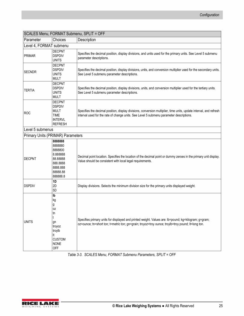
SCALES Menu, FORMAT Submenu, SPLIT = OFFParameter Choices DescriptionLevel 4, FORMAT submenu
PRIMARDECPNTDSPDIVUNITS
Specifies the decimal position, display divisions, and units used for the primary units. See Level 5 submenu parameter descriptions.
SECNDR
DECPNTDSPDIVUNITSMULT
Specifies the decimal position, display divisions, units, and conversion multiplier used for the secondary units. See Level 5 submenu parameter descriptions.
TERTIA
DECPNTDSPDIVUNITSMULT
Specifies the decimal position, display divisions, units, and conversion multiplier used for the tertiary units. See Level 5 submenu parameter descriptions.
ROC
DECPNTDSPDIVMULTTIMEINTERVLREFRESH
Specifies the decimal position, display divisions, conversion multiplier, time units, update interval, and refresh interval used for the rate of change units. See Level 5 submenu parameter descriptions.
Level 5 submenus Primary Units (PRIMAR) Parameters
DECPNT
8888888888888088888008.88888888.88888888.88888888.88888888.88888888.8
Decimal point location. Specifies the location of the decimal point or dummy zeroes in the primary unit display. Value should be consistent with local legal requirements.
DSPDIV1D2D5D
Display divisions. Selects the minimum division size for the primary units displayed weight.
UNITS
lbkggoztntgntroyoztroylbltCUSTOMNONEOFF
Specifies primary units for displayed and printed weight. Values are: lb=pound; kg=kilogram; g=gram; oz=ounce; tn=short ton; t=metric ton; gn=grain; troyoz=troy ounce; troylb=troy pound; lt=long ton.
Table 3-3. SCALES Menu, FORMAT Submenu Parameters, SPLIT = OFF
820i Programmable HMI Indicator/Controller
26 Visit our website www.RiceLake.com
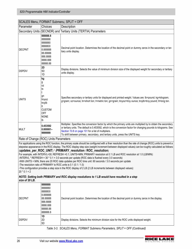
Secondary Units (SECNDR) and Tertiary Units (TERTIA) Parameters
DECPNT
888888.88888888888888088888008.88888888.88888888.88888888.88888888.88
Decimal point location. Determines the location of the decimal point or dummy zeros in the secondary or ter-tiary units display.
DSPDIV2D5D1D
Display divisions. Selects the value of minimum division size of the displayed weight for secondary or tertiary units display.
UNITS
kggoztntgntroyoztroylbltCUSTOMOFFNONElb
Specifies secondary or tertiary units for displayed and printed weight. Values are: lb=pound; kg=kilogram; g=gram; oz=ounce; tn=short ton; t=metric ton; gn=grain; troyoz=troy ounce; troylb=troy pound; lt=long ton.
MULT0.4535920.000001–9999999
Multiplier. Specifies the conversion factor by which the primary units are multiplied by to obtain the secondary or tertiary units. The default is 0.453592, which is the conversion factor for changing pounds to kilograms. See Section 10.8 on page 101 for a list of multipliers. To shift between primary, secondary, and tertiary units, press the UNITS key.
Rate of Change (ROC) Units ParametersFor applications using the ROC function, the primary scale should be configured with a finer resolution than the rate of change (ROC) units to prevent a stepwise appearance in the ROC display. The ROC display step size (weight increment between displayed values) can be roughly calculated as follows:(updates_per_ROC_UNIT) * (PRIMARY_resolution / ROC_resolution)For example, with INTERVL=30; REFRESH =0.1; UNITS=MIN; PRIMARY resolution at 0.1 LB and ROC resolution at 1.0 (LB/MIN):-INTERVL * REFRESH = 30 * 0.1 = 3.0 seconds per update (ROC data is flushed every 3.0 seconds)-With UNITS = MIN, there are 20 ROC data updates per ROC time unit: 60 seconds / 3.0 seconds per update-The resolution ratio of PRIMARY to ROC units is 0.1 (0.1 / 1.0)-This configuration provides a step size in the ROC display of 2 LB (2 LB increments between displayed values):20 * 0.1 = 2
NOTE: Setting both PRIMARY and ROC display resolutions to 1 LB would have resulted in a step size of 20 LB.
DECPNT
8888888888888088888008.88888888.88888888.88888888.88888888.88888888.8
Decimal point location. Determines the location of the decimal point or dummy zeros in the display.
DSPDIV1D2D5D
Display divisions. Selects the minimum division size for the ROC units displayed weight.
SCALES Menu, FORMAT Submenu, SPLIT = OFFParameter Choices Description
Table 3-3. SCALES Menu, FORMAT Submenu Parameters, SPLIT = OFF (Continued)
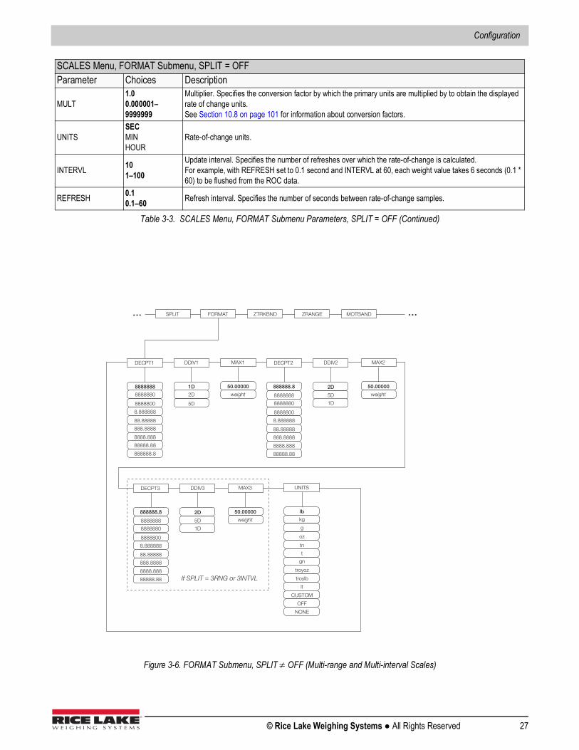
Configuration
© Rice Lake Weighing Systems ● All Rights Reserved 27
Figure 3-6. FORMAT Submenu, SPLIT OFF (Multi-range and Multi-interval Scales)
MULT1.00.000001–9999999
Multiplier. Specifies the conversion factor by which the primary units are multiplied by to obtain the displayed rate of change units. See Section 10.8 on page 101 for information about conversion factors.
UNITSSECMINHOUR
Rate-of-change units.
INTERVL 101–100
Update interval. Specifies the number of refreshes over which the rate-of-change is calculated. For example, with REFRESH set to 0.1 second and INTERVL at 60, each weight value takes 6 seconds (0.1 * 60) to be flushed from the ROC data.
REFRESH 0.10.1–60 Refresh interval. Specifies the number of seconds between rate-of-change samples.
SCALES Menu, FORMAT Submenu, SPLIT = OFFParameter Choices Description
Table 3-3. SCALES Menu, FORMAT Submenu Parameters, SPLIT = OFF (Continued)
FORMAT ZRANGE MOTBAND ZTRKBND … … SPLIT
DECPT1
88.88888
888.8888
8888888
8888800
8888880
8.888888
8888.888
88888.88
888888.8
DDIV1
1D
5D
2D
UNITS
tn
t
lb
g
kg
oz
gn
troyoz
troylb
lt
CUSTOM
NONE
OFF
MAX1
50.00000
weight
DECPT2
88.88888
888.8888
8888888
8888800
8888880
8.888888
8888.888
88888.88
888888.8
DDIV2
5D
2D
1D
MAX2
50.00000
weight
DECPT3
88.88888
888.8888
8888888
8888800
8888880
8.888888
8888.888
88888.88
888888.8
DDIV3
5D
2D
1D
MAX3
50.00000
weight
If SPLIT = 3RNG or 3INTVL
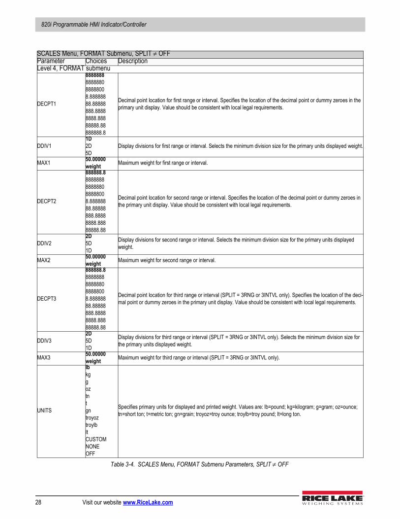
820i Programmable HMI Indicator/Controller
28 Visit our website www.RiceLake.com
SCALES Menu, FORMAT Submenu, SPLIT OFFParameter Choices DescriptionLevel 4, FORMAT submenu
DECPT1
8888888888888088888008.88888888.88888888.88888888.88888888.88888888.8
Decimal point location for first range or interval. Specifies the location of the decimal point or dummy zeroes in the primary unit display. Value should be consistent with local legal requirements.
DDIV11D2D5D
Display divisions for first range or interval. Selects the minimum division size for the primary units displayed weight.
MAX1 50.00000weight Maximum weight for first range or interval.
DECPT2
888888.88888888888888088888008.88888888.88888888.88888888.88888888.88
Decimal point location for second range or interval. Specifies the location of the decimal point or dummy zeroes in the primary unit display. Value should be consistent with local legal requirements.
DDIV22D5D1D
Display divisions for second range or interval. Selects the minimum division size for the primary units displayed weight.
MAX2 50.00000weight Maximum weight for second range or interval.
DECPT3
888888.88888888888888088888008.88888888.88888888.88888888.88888888.88
Decimal point location for third range or interval (SPLIT = 3RNG or 3INTVL only). Specifies the location of the deci-mal point or dummy zeroes in the primary unit display. Value should be consistent with local legal requirements.
DDIV32D5D1D
Display divisions for third range or interval (SPLIT = 3RNG or 3INTVL only). Selects the minimum division size for the primary units displayed weight.
MAX3 50.00000weight Maximum weight for third range or interval (SPLIT = 3RNG or 3INTVL only).
UNITS
lbkggoztntgntroyoztroylbltCUSTOMNONEOFF
Specifies primary units for displayed and printed weight. Values are: lb=pound; kg=kilogram; g=gram; oz=ounce; tn=short ton; t=metric ton; gn=grain; troyoz=troy ounce; troylb=troy pound; lt=long ton.
Table 3-4. SCALES Menu, FORMAT Submenu Parameters, SPLIT OFF
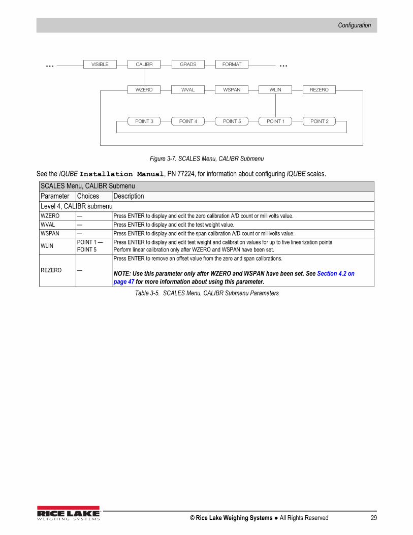
Configuration
© Rice Lake Weighing Systems ● All Rights Reserved 29
Figure 3-7. SCALES Menu, CALIBR Submenu
See the iQUBE Installation Manual, PN 77224, for information about configuring iQUBE scales.SCALES Menu, CALIBR SubmenuParameter Choices DescriptionLevel 4, CALIBR submenuWZERO — Press ENTER to display and edit the zero calibration A/D count or millivolts value.WVAL — Press ENTER to display and edit the test weight value.WSPAN — Press ENTER to display and edit the span calibration A/D count or millivolts value.
WLIN POINT 1 — POINT 5
Press ENTER to display and edit test weight and calibration values for up to five linearization points.Perform linear calibration only after WZERO and WSPAN have been set.
REZERO —
Press ENTER to remove an offset value from the zero and span calibrations.
NOTE: Use this parameter only after WZERO and WSPAN have been set. See Section 4.2 on page 47 for more information about using this parameter.
Table 3-5. SCALES Menu, CALIBR Submenu Parameters
WZERO WVAL WSPAN WLIN REZERO
POINT 4 POINT 5 POINT 1 POINT 2 POINT 3
VISIBLE GRADS FORMAT CALIBR … …
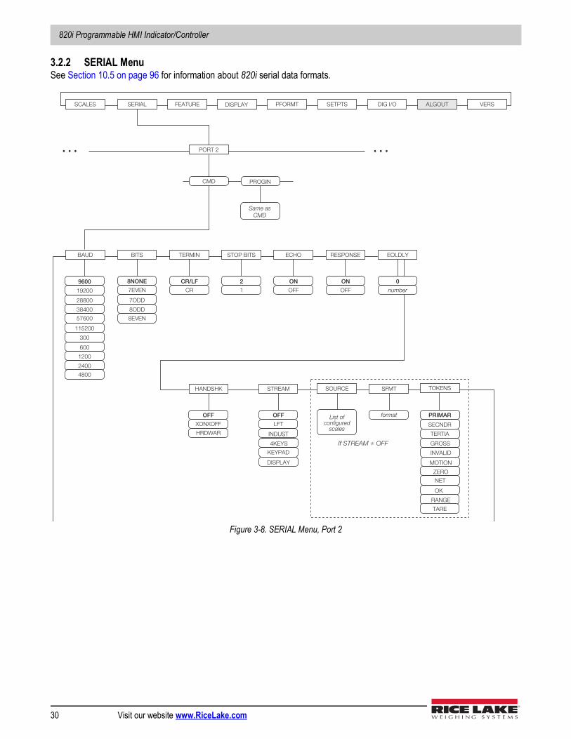
820i Programmable HMI Indicator/Controller
30 Visit our website www.RiceLake.com
3.2.2 SERIAL MenuSee Section 10.5 on page 96 for information about 820i serial data formats.
Figure 3-8. SERIAL Menu, Port 2
SCALES SERIAL FEATURE PFORMT SETPTS DIG I/O ALGOUT VERS
BAUD TERMINBITS
600
1200
38400
57600
300
2400
28800
9600
4800
19200
8NONE
7ODD
7EVEN
CR/LF
CR
EOLDLY
0
number
HANDSHK
OFF
HRDWAR
STREAM
OFF
INDUST
LFT
SOURCE
List ofconfigured
scales
If STREAM ≠ OFF
SFMT
format
XONXOFF
8ODD
8EVEN
STOP BITS
2
1
ECHO
ON
OFF
RESPONSE
ON
OFF
PORT 2
PROGIN
Same asCMD
…
CMD
115200
DISPLAY
4KEYS
DISPLAY
KEYPAD
…
TOKENS
PRIMAR
SECNDR
TERTIA
GROSS
INVALID
MOTION
ZERO
NET
OK
RANGE
TARE
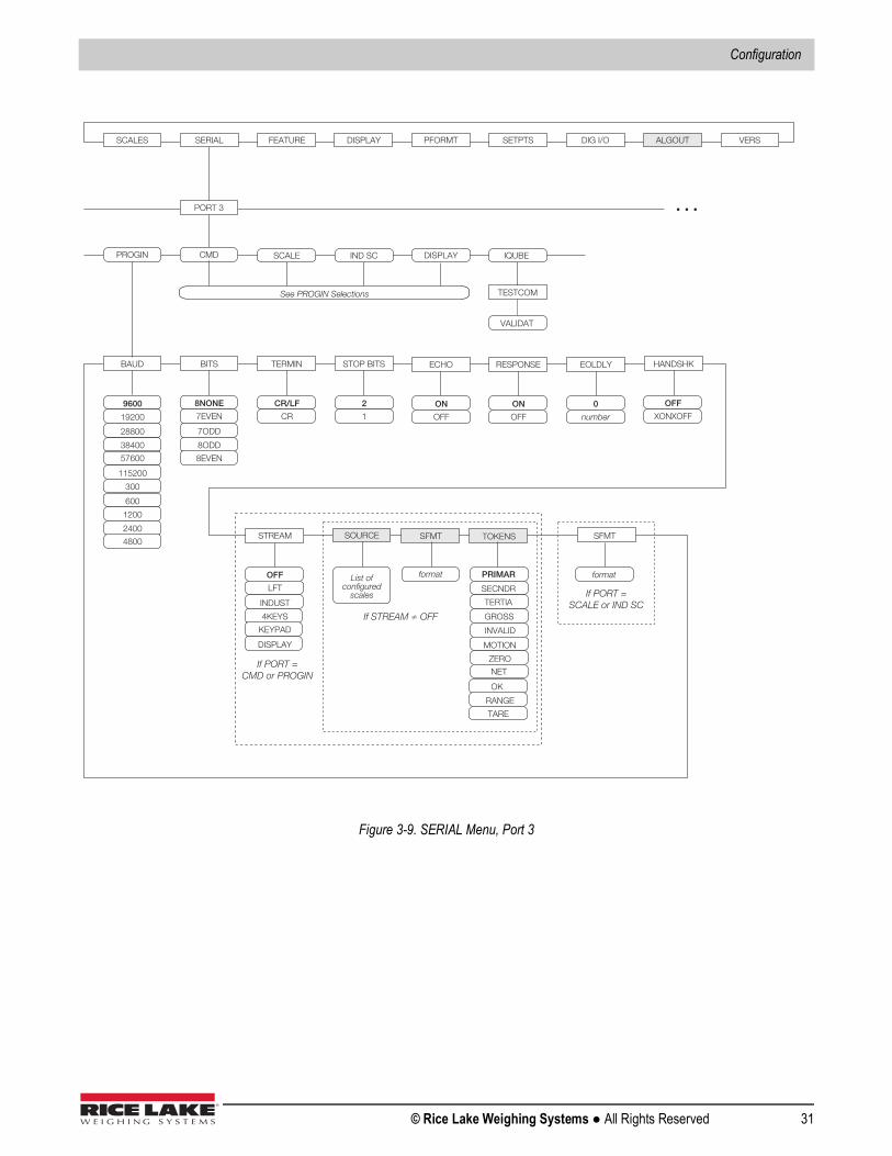
Configuration
© Rice Lake Weighing Systems ● All Rights Reserved 31
Figure 3-9. SERIAL Menu, Port 3
SFMT
format
If PORT =SCALE or IND SC
STREAM
OFF
INDUST
LFT
SOURCE
List of configured
scales
If STREAM ≠ OFF
SFMT
format
If PORT = CMD or PROGIN
4KEYS
DISPLAY
KEYPAD
TOKENS
PRIMAR
SECNDR
TERTIA
GROSS
INVALID
MOTION
ZERO
NET
OK
RANGE
TARE
SCALES SERIAL FEATURE PFORMT SETPTS DIG I/O ALGOUT VERS
PORT 3
BAUD TERMIN BITS
600
1200
38400
115200
57600
300
2400
28800
9600
4800
19200
8NONE
7ODD
7EVEN
CR/LF
CR
HANDSHK
OFF
XONXOFF
PROGIN
8ODD
8EVEN
STOP BITS
2
1
CMD
See PROGIN Selections
…
SCALE IND SC
EOLDLY
0
number
ECHO
ON
OFF
RESPONSE
ON
OFF
DISPLAY
IQUBE
TESTCOM
VALIDAT
DISPLAY
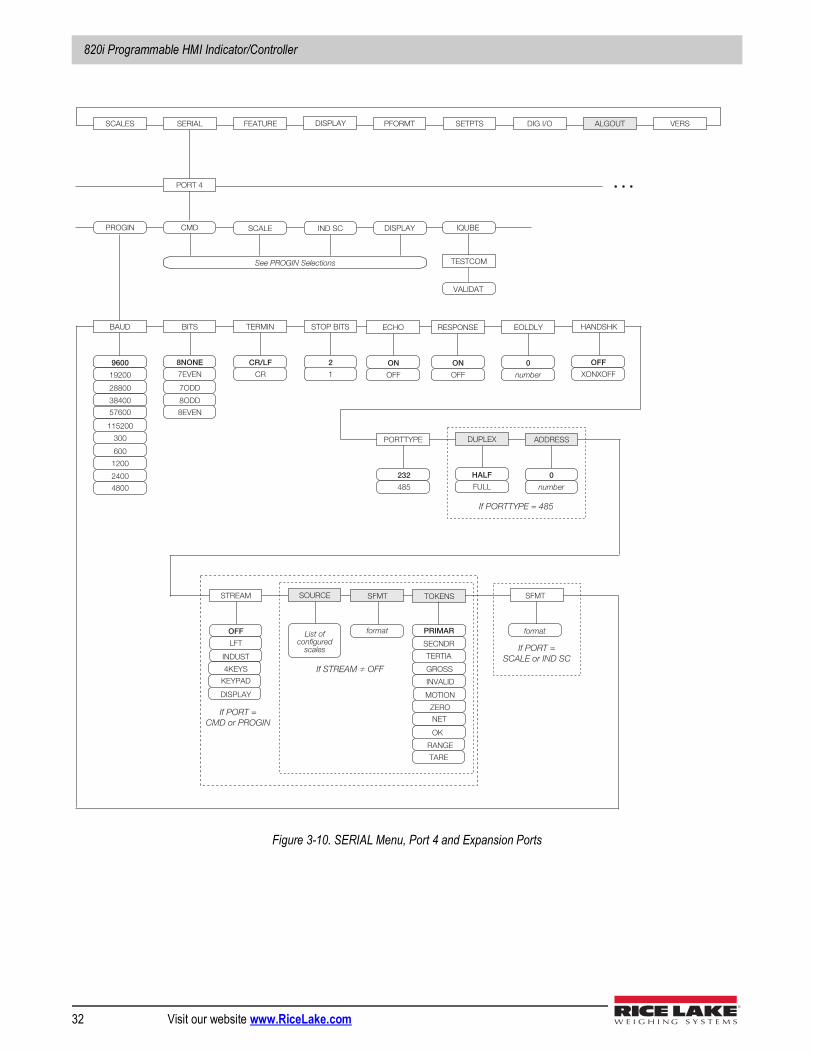
820i Programmable HMI Indicator/Controller
32 Visit our website www.RiceLake.com
Figure 3-10. SERIAL Menu, Port 4 and Expansion Ports
SCALES SERIAL FEATURE PFORMT SETPTS DIG I/O ALGOUT VERS
PORT 4
BAUD TERMINBITS
600
1200
38400
115200
57600
300
2400
28800
9600
4800
19200
8NONE
7ODD
7EVEN
CR/LF
CR
PROGIN
8ODD
8EVEN
STOP BITS
2
1
CMD
See PROGIN Selections
…
SCALE IND SC
ADDRESS
0
number
PORTTYPE
232
485
DUPLEX
HALF
FULL
If PORTTYPE = 485
HANDSHK
OFF
XONXOFF
EOLDLY
0
number
ECHO
ON
OFF
RESPONSE
ON
OFF
DISPLAY
IQUBE
TESTCOM
VALIDAT
DISPLAY
SFMT
format
If PORT =SCALE or IND SC
STREAM
OFF
INDUST
LFT
SOURCE
List ofconfigured
scales
If STREAM ≠ OFF
SFMT
format
If PORT =CMD or PROGIN
4KEYS
DISPLAY
KEYPAD
TOKENS
PRIMAR
SECNDR
TERTIA
GROSS
INVALID
MOTION
ZERO
NET
OK
RANGE
TARE
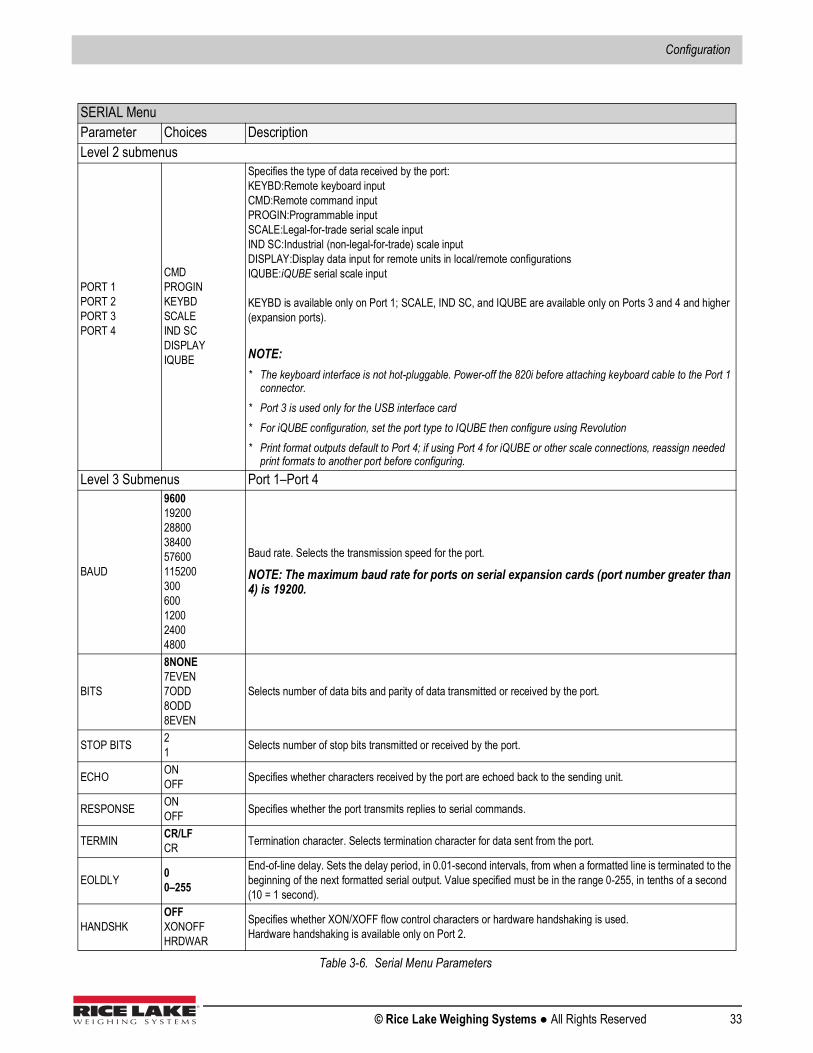
Configuration
© Rice Lake Weighing Systems ● All Rights Reserved 33
SERIAL MenuParameter Choices DescriptionLevel 2 submenus
PORT 1PORT 2PORT 3PORT 4
CMDPROGINKEYBDSCALEIND SCDISPLAYIQUBE
Specifies the type of data received by the port: KEYBD:Remote keyboard inputCMD:Remote command input PROGIN:Programmable inputSCALE:Legal-for-trade serial scale inputIND SC:Industrial (non-legal-for-trade) scale inputDISPLAY:Display data input for remote units in local/remote configurationsIQUBE:iQUBE serial scale input
KEYBD is available only on Port 1; SCALE, IND SC, and IQUBE are available only on Ports 3 and 4 and higher (expansion ports).
NOTE:* The keyboard interface is not hot-pluggable. Power-off the 820i before attaching keyboard cable to the Port 1
connector.* Port 3 is used only for the USB interface card* For iQUBE configuration, set the port type to IQUBE then configure using Revolution* Print format outputs default to Port 4; if using Port 4 for iQUBE or other scale connections, reassign needed
print formats to another port before configuring.Level 3 Submenus Port 1–Port 4
BAUD
960019200288003840057600115200300600120024004800
Baud rate. Selects the transmission speed for the port.
NOTE: The maximum baud rate for ports on serial expansion cards (port number greater than 4) is 19200.
BITS
8NONE7EVEN7ODD8ODD8EVEN
Selects number of data bits and parity of data transmitted or received by the port.
STOP BITS 21 Selects number of stop bits transmitted or received by the port.
ECHO ONOFF Specifies whether characters received by the port are echoed back to the sending unit.
RESPONSE ONOFF Specifies whether the port transmits replies to serial commands.
TERMIN CR/LFCR Termination character. Selects termination character for data sent from the port.
EOLDLY 00–255
End-of-line delay. Sets the delay period, in 0.01-second intervals, from when a formatted line is terminated to the beginning of the next formatted serial output. Value specified must be in the range 0-255, in tenths of a second (10 = 1 second).
HANDSHKOFFXONOFFHRDWAR
Specifies whether XON/XOFF flow control characters or hardware handshaking is used.Hardware handshaking is available only on Port 2.
Table 3-6. Serial Menu Parameters
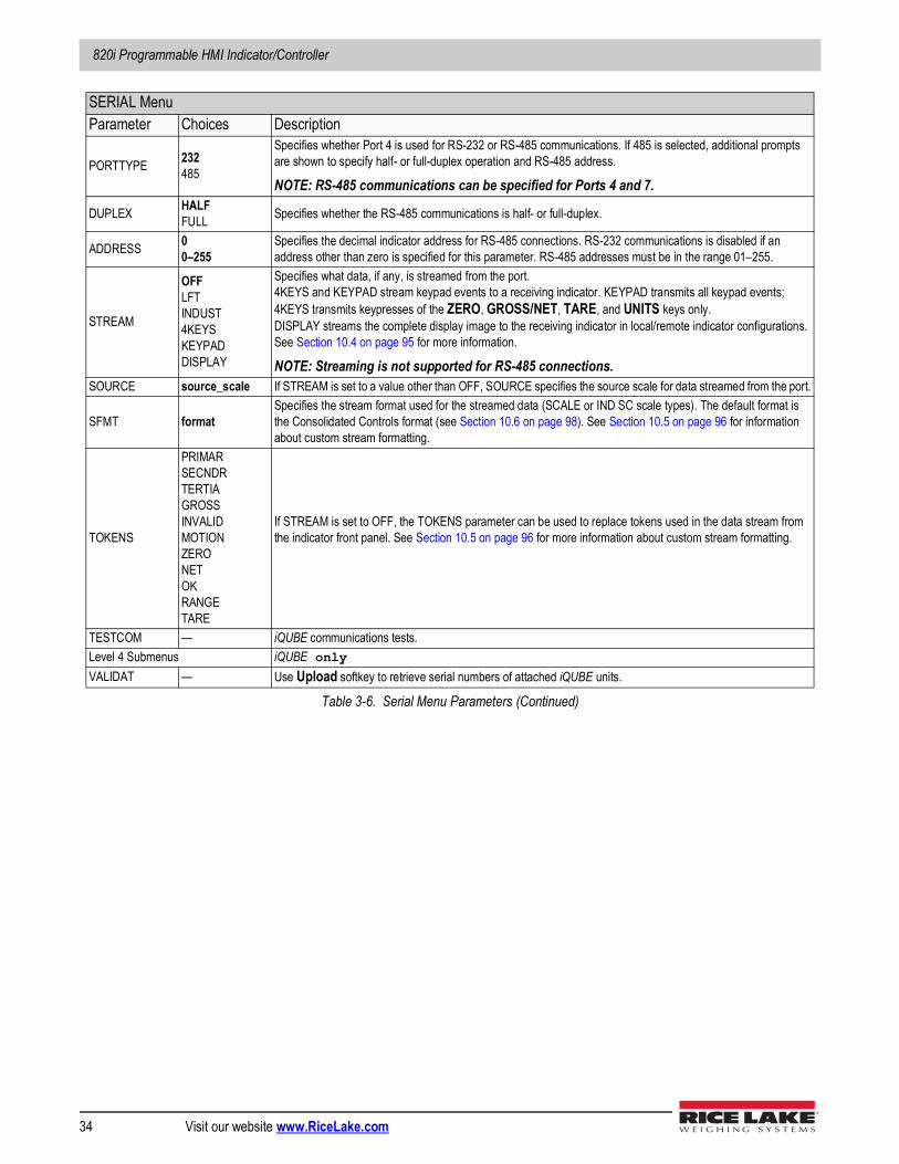
820i Programmable HMI Indicator/Controller
34 Visit our website www.RiceLake.com
PORTTYPE 232485
Specifies whether Port 4 is used for RS-232 or RS-485 communications. If 485 is selected, additional prompts are shown to specify half- or full-duplex operation and RS-485 address.
NOTE: RS-485 communications can be specified for Ports 4 and 7.
DUPLEX HALFFULL Specifies whether the RS-485 communications is half- or full-duplex.
ADDRESS 00–255
Specifies the decimal indicator address for RS-485 connections. RS-232 communications is disabled if an address other than zero is specified for this parameter. RS-485 addresses must be in the range 01–255.
STREAM
OFFLFTINDUST4KEYSKEYPADDISPLAY
Specifies what data, if any, is streamed from the port.4KEYS and KEYPAD stream keypad events to a receiving indicator. KEYPAD transmits all keypad events; 4KEYS transmits keypresses of the ZERO, GROSS/NET, TARE, and UNITS keys only.DISPLAY streams the complete display image to the receiving indicator in local/remote indicator configurations. See Section 10.4 on page 95 for more information.
NOTE: Streaming is not supported for RS-485 connections.SOURCE source_scale If STREAM is set to a value other than OFF, SOURCE specifies the source scale for data streamed from the port.
SFMT formatSpecifies the stream format used for the streamed data (SCALE or IND SC scale types). The default format is the Consolidated Controls format (see Section 10.6 on page 98). See Section 10.5 on page 96 for information about custom stream formatting.
TOKENS
PRIMARSECNDRTERTIAGROSSINVALIDMOTIONZERONETOKRANGETARE
If STREAM is set to OFF, the TOKENS parameter can be used to replace tokens used in the data stream from the indicator front panel. See Section 10.5 on page 96 for more information about custom stream formatting.
TESTCOM — iQUBE communications tests.Level 4 Submenus iQUBE onlyVALIDAT — Use Upload softkey to retrieve serial numbers of attached iQUBE units.
SERIAL MenuParameter Choices Description
Table 3-6. Serial Menu Parameters (Continued)
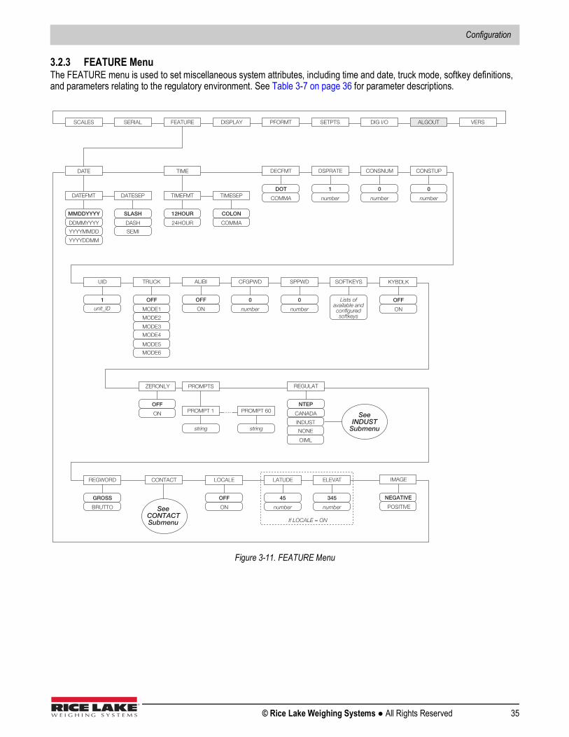
Configuration
© Rice Lake Weighing Systems ● All Rights Reserved 35
3.2.3 FEATURE MenuThe FEATURE menu is used to set miscellaneous system attributes, including time and date, truck mode, softkey definitions, and parameters relating to the regulatory environment. See Table 3-7 on page 36 for parameter descriptions.
Figure 3-11. FEATURE Menu
SCALES SERIAL FEATURE PFORMT SETPTS DIG I/O ALGOUT VERS
DA TE
DA TEFMT DATESEP
DDMMYYYY
YYYYMMDD
MMDDYYYY
YYYYDDMM
DASH
SEMI
SLASH
TIME
TIMEFMT TIMESEP
24HOUR
12HOUR
COMMA
COLON
DECFMT
COMMA
DOT
DSPRATE
number
1
CONSNUM
number
0
CONSTUP
number
0
UID
unit_ID
1
TRUCK
MODE1
MODE2
OFF
MODE3
MODE4
MODE5
MODE6
CFGPWD
number
0
SPPWD
number
0
SOFTKEYS KYBDLK
ON
OFF
ZERONLY
ON
OFF
PROMPTS
PROMPT 1
string
PROMPT 60
string
…
REGULAT
CANADA
NTEP
OIML
NONE
Lists of available and configured softkeys
LOCALE
ON
OFF
LATUDE
number
45
ELEVAT
number
345
If LOCALE = ON
REGWORD
BRUTTO
GROSS
INDUST
See INDUST
Submenu
DISPLAY
ALIBI
ON
OFF
CONTACT
See CONTACT Submenu
IMAGE
POSITIVE
NEGATIVE
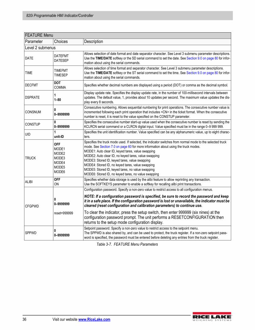
820i Programmable HMI Indicator/Controller
36 Visit our website www.RiceLake.com
FEATURE MenuParameter Choices DescriptionLevel 2 submenus
DATE DATEFMTDATESEP
Allows selection of date format and date separator character. See Level 3 submenu parameter descriptions.Use the TIME/DATE softkey or the SD serial command to set the date. See Section 9.0 on page 80 for infor-mation about using the serial commands.
TIME TIMEFMTTIMESEP
Allows selection of time format and separator character. See Level 3 submenu parameter descriptions.Use the TIME/DATE softkey or the ST serial command to set the time. See Section 9.0 on page 80 for infor-mation about using the serial commands.
DECFMT DOTCOMMA Specifies whether decimal numbers are displayed using a period (DOT) or comma as the decimal symbol.
DSPRATE 11–80
Display update rate. Specifies the display update rate, in the number of 100-millisecond intervals between updates. The default value, 1, provides about 10 updates per second. The maximum value updates the dis-play every 8 seconds.
CONSNUM 00–9999999
Consecutive numbering. Allows sequential numbering for print operations. The consecutive number value is incremented following each print operation that includes <CN> in the ticket format. When the consecutive number is reset, it is reset to the value specified on the CONSTUP parameter.
CONSTUP 00–9999999
Specifies the consecutive number start-up value used when the consecutive number is reset by sending the KCLRCN serial command or a CLRCN digital input. Value specified must be in the range 0–9 999 999.
UID 1unit-ID
Specifies the unit identification number. Value specified can be any alphanumeric value, up to eight charac-ters.
TRUCK
OFFMODE1MODE2MODE3MODE4MODE5MODE6
Specifies the truck mode used. If selected, the indicator switches from normal mode to the selected truck mode. See Section 7.0 on page 60 for more information about using the truck modes.MODE1: Auto clear ID, keyed tares, value swappingMODE2: Auto clear ID, no keyed tares, value swappingMODE3: Stored ID, keyed tares, value swappingMODE4: Stored ID, no keyed tares, value swappingMODE5: Stored ID, keyed tares, no value swappingMODE6: Stored ID, no keyed tares, no value swapping
ALIBI OFFON
Specifies whether data storage is used by the alibi feature to allow reprinting any transaction.Use the SOFTKEYS parameter to enable a softkey for recalling alibi print transactions.
CFGPWD
00–9999999
reset=999999
Configuration password. Specify a non-zero value to restrict access to all configuration menus.
NOTE: If a configuration password is specified, be sure to record the password and keep it in a safe place. If the configuration password is lost or unavailable, the indicator must be cleared (reset configuration and calibration parameters) to continue use.To clear the indicator, press the setup switch, then enter 999999 (six nines) at the configuration password prompt. The unit performs a RESETCONFIGURATION then returns to the setup mode configuration display.
SPPWD 00–9999999
Setpoint password. Specify a non-zero value to restrict access to the setpoint menu.The SPPWD is also shared by, and can be used to protect, the truck register. If a non-zero setpoint pass-word is specified, the password must be entered before deleting any entries from the truck register.
Table 3-7. FEATURE Menu Parameters
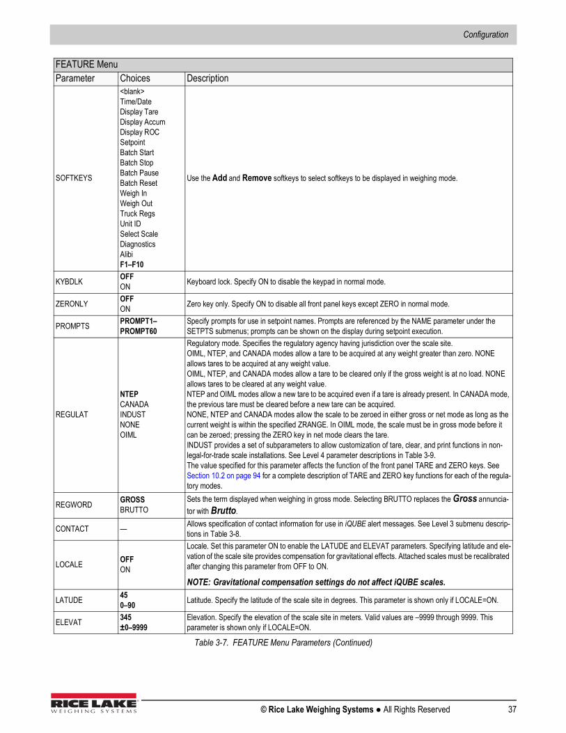
Configuration
© Rice Lake Weighing Systems ● All Rights Reserved 37
SOFTKEYS
<blank>Time/DateDisplay TareDisplay AccumDisplay ROCSetpointBatch StartBatch StopBatch PauseBatch ResetWeigh InWeigh OutTruck RegsUnit IDSelect ScaleDiagnosticsAlibiF1–F10
Use the Add and Remove softkeys to select softkeys to be displayed in weighing mode.
KYBDLK OFFON Keyboard lock. Specify ON to disable the keypad in normal mode.
ZERONLY OFFON Zero key only. Specify ON to disable all front panel keys except ZERO in normal mode.
PROMPTS PROMPT1–PROMPT60
Specify prompts for use in setpoint names. Prompts are referenced by the NAME parameter under the SETPTS submenus; prompts can be shown on the display during setpoint execution.
REGULAT
NTEPCANADAINDUSTNONEOIML
Regulatory mode. Specifies the regulatory agency having jurisdiction over the scale site.OIML, NTEP, and CANADA modes allow a tare to be acquired at any weight greater than zero. NONE allows tares to be acquired at any weight value.OIML, NTEP, and CANADA modes allow a tare to be cleared only if the gross weight is at no load. NONE allows tares to be cleared at any weight value.NTEP and OIML modes allow a new tare to be acquired even if a tare is already present. In CANADA mode, the previous tare must be cleared before a new tare can be acquired.NONE, NTEP and CANADA modes allow the scale to be zeroed in either gross or net mode as long as the current weight is within the specified ZRANGE. In OIML mode, the scale must be in gross mode before it can be zeroed; pressing the ZERO key in net mode clears the tare.INDUST provides a set of subparameters to allow customization of tare, clear, and print functions in non-legal-for-trade scale installations. See Level 4 parameter descriptions in Table 3-9.The value specified for this parameter affects the function of the front panel TARE and ZERO keys. See Section 10.2 on page 94 for a complete description of TARE and ZERO key functions for each of the regula-tory modes.
REGWORD GROSSBRUTTO
Sets the term displayed when weighing in gross mode. Selecting BRUTTO replaces the Gross annuncia-tor with Brutto.
CONTACT — Allows specification of contact information for use in iQUBE alert messages. See Level 3 submenu descrip-tions in Table 3-8.
LOCALE OFFON
Locale. Set this parameter ON to enable the LATUDE and ELEVAT parameters. Specifying latitude and ele-vation of the scale site provides compensation for gravitational effects. Attached scales must be recalibrated after changing this parameter from OFF to ON.
NOTE: Gravitational compensation settings do not affect iQUBE scales.
LATUDE 450–90 Latitude. Specify the latitude of the scale site in degrees. This parameter is shown only if LOCALE=ON.
ELEVAT 345±0–9999
Elevation. Specify the elevation of the scale site in meters. Valid values are –9999 through 9999. This parameter is shown only if LOCALE=ON.
FEATURE MenuParameter Choices Description
Table 3-7. FEATURE Menu Parameters (Continued)
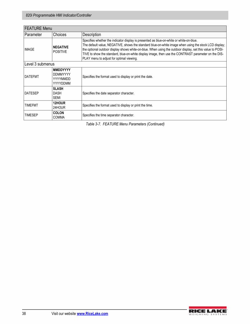
820i Programmable HMI Indicator/Controller
38 Visit our website www.RiceLake.com
IMAGE NEGATIVEPOSITIVE
Specifies whether the indicator display is presented as blue-on-white or white-on-blue. The default value, NEGATIVE, shows the standard blue-on-white image when using the stock LCD display; the optional outdoor display shows white-on-blue. When using the outdoor display, set this value to POSI-TIVE to show the standard, blue-on-white display image, then use the CONTRAST parameter on the DIS-PLAY menu to adjust for optimal viewing.
Level 3 submenus
DATEFMT
MMDDYYYYDDMMYYYYYYYYMMDDYYYYDDMM
Specifies the format used to display or print the date.
DATESEPSLASHDASHSEMI
Specifies the date separator character.
TIMEFMT 12HOUR24HOUR Specifies the format used to display or print the time.
TIMESEP COLONCOMMA Specifies the time separator character.
FEATURE MenuParameter Choices Description
Table 3-7. FEATURE Menu Parameters (Continued)
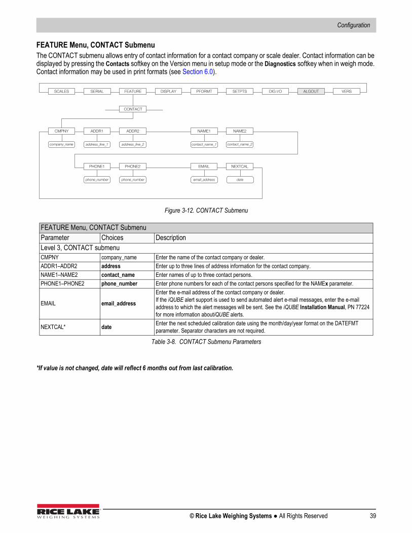
Configuration
© Rice Lake Weighing Systems ● All Rights Reserved 39
FEATURE Menu, CONTACT SubmenuThe CONTACT submenu allows entry of contact information for a contact company or scale dealer. Contact information can be displayed by pressing the Contacts softkey on the Version menu in setup mode or the Diagnostics softkey when in weigh mode. Contact information may be used in print formats (see Section 6.0).
Figure 3-12. CONTACT Submenu
*If value is not changed, date will reflect 6 months out from last calibration.
FEATURE Menu, CONTACT SubmenuParameter Choices DescriptionLevel 3, CONTACT submenuCMPNY company_name Enter the name of the contact company or dealer.ADDR1–ADDR2 address Enter up to three lines of address information for the contact company.NAME1–NAME2 contact_name Enter names of up to three contact persons.PHONE1–PHONE2 phone_number Enter phone numbers for each of the contact persons specified for the NAMEx parameter.
EMAIL email_address
Enter the e-mail address of the contact company or dealer. If the iQUBE alert support is used to send automated alert e-mail messages, enter the e-mail address to which the alert messages will be sent. See the iQUBE Installation Manual, PN 77224 for more information aboutiQUBE alerts.
NEXTCAL* date Enter the next scheduled calibration date using the month/day/year format on the DATEFMT parameter. Separator characters are not required.
Table 3-8. CONTACT Submenu Parameters
address_line_1 address_line_2 contact_name_1
SCALES SERIAL FEATURE PFORMT SETPTS DIG I/O ALGOUT VERS
CONTACT
CMPNY ADDR1 ADDR2 NAME1 NAME2
PHONE1 PHONE2 EMAIL
phone_number phone_number email_address
contact_name_2 company_nam e
NEXTCAL
date
DISPLAY
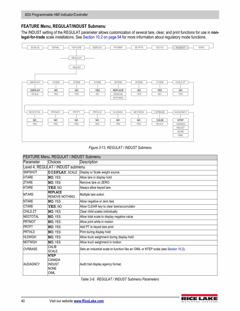
820i Programmable HMI Indicator/Controller
40 Visit our website www.RiceLake.com
FEATURE Menu, REGULAT/INDUST SubmenuThe INDUST setting of the REGULAT parameter allows customization of several tare, clear, and print functions for use in non-legal-for-trade scale installations. See Section 10.2 on page 94 for more information about regulatory mode functions.
Figure 3-13. REGULAT / INDUST Submenu
FEATURE Menu, REGULAT / INDUST SubmenuParameter Choices DescriptionLevel 4, REGULAT / INDUST submenuSNPSHOT DISPLAY, SCALE Display or Scale weight source.HTARE NO, YES Allow tare in display holdZTARE NO, YES Remove tare on ZEROKTARE YES, NO Always allow keyed tare
MTARE REPLACEREMOVE NOTHING Multiple tare action
NTARE NO, YES Allow negative or zero tareCTARE YES, NO Allow CLEAR key to clear tare/accumulatorCHILD ZT NO, YES Clear child scales individuallyNEGTOTAL NO, YES Allow total scale to display negative valuePRTMOT NO, YES Allow print while in motionPRTPT NO, YES Add PT to keyed tare printPRTHLD NO, YES Print during display holdHLDWGH NO, YES Allow truck weighment during display holdMOTWGH NO, YES Allow truck weighment in motion
OVRBASE CALIBSCALE Sets an industrial scale to function like an OIML or NTEP scale (see Section 10.2).
AUDAGNCY
NTEPCANADAINDUSTNONEOIML
Audit trail display agency format.
Table 3-9. REGULAT / INDUST Submenu Parameters
SCALES SERIAL FEATURE PFORMT SETPTS DIG I/O ALGOUT VERS
REGULAT
SNPSHOT
DISPLAY
INDUST
SCALE
HTARE
NO
YES
ZTARE
NO
YES
KTARE
YES
NO
MTARE
REPLACE
REMOVE
NOTHING
NTARE
NO
YES
CTARE
YES
NO
PRTMOT
NO
YES
PRTPT
NO
YES
PRTHLD
NO
YES
HLDWGH
NO
YES
MOTWGH
NO
YES
CHILD ZT
NO
YES
NEGTOTAL
NO
YES
DISPLAY
AUDAGNCY
NTEP
CANADA
INDUST
NONE
OIML
OVRBASE
CALIB
SCALE
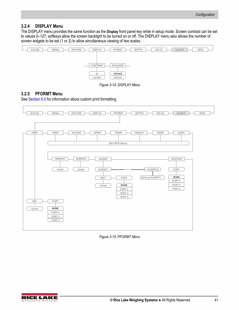
Configuration
© Rice Lake Weighing Systems ● All Rights Reserved 41
3.2.4 DISPLAY MenuThe DISPLAY menu provides the same function as the Display front panel key while in setup mode. Screen contrast can be set to values 0–127; softkeys allow the screen backlight to be turned on or off. The DISPLAY menu also allows the number of screen widgets to be set (1 or 2) to allow simultaneous viewing of two scales.
Figure 3-14. DISPLAY Menu
3.2.5 PFORMT MenuSee Section 6.0 for information about custom print formatting.
Figure 3-15. PFORMT Menu
SCALES SERIAL FEATURE PFORMT SETPTS DIG I/O ALGOUT VERS DISPLAY
number
0
CONTRAST
2SCALE
1SCALE
SCALEDSP
SCALES SERIAL FEATURE PFORMT SETPTS DIG I/O ALGOUT VERS
GFMT NFMT ACCFMT SPFMT TRWIN TRWOUT TRFMT
See GFMT Menus
PORTFMT
format
HDRFMT1 HDRFMT2 AUXFMT
format format
ALERT
Same as AUXFMT1
SERV
Alert emailserver
PHONE
Alert modemphone
ALERT format ONLY
AUDITFMT
PORTAUXFMT1 AUXFMT20
PORTFMT1
format
...
DISPLAY
PORT 2
PORT 4
PORT 3
PORT 2
PORT 4
PORT 3
PORT 2
PORT 4
PORT 3
NONE
NONE
NONE
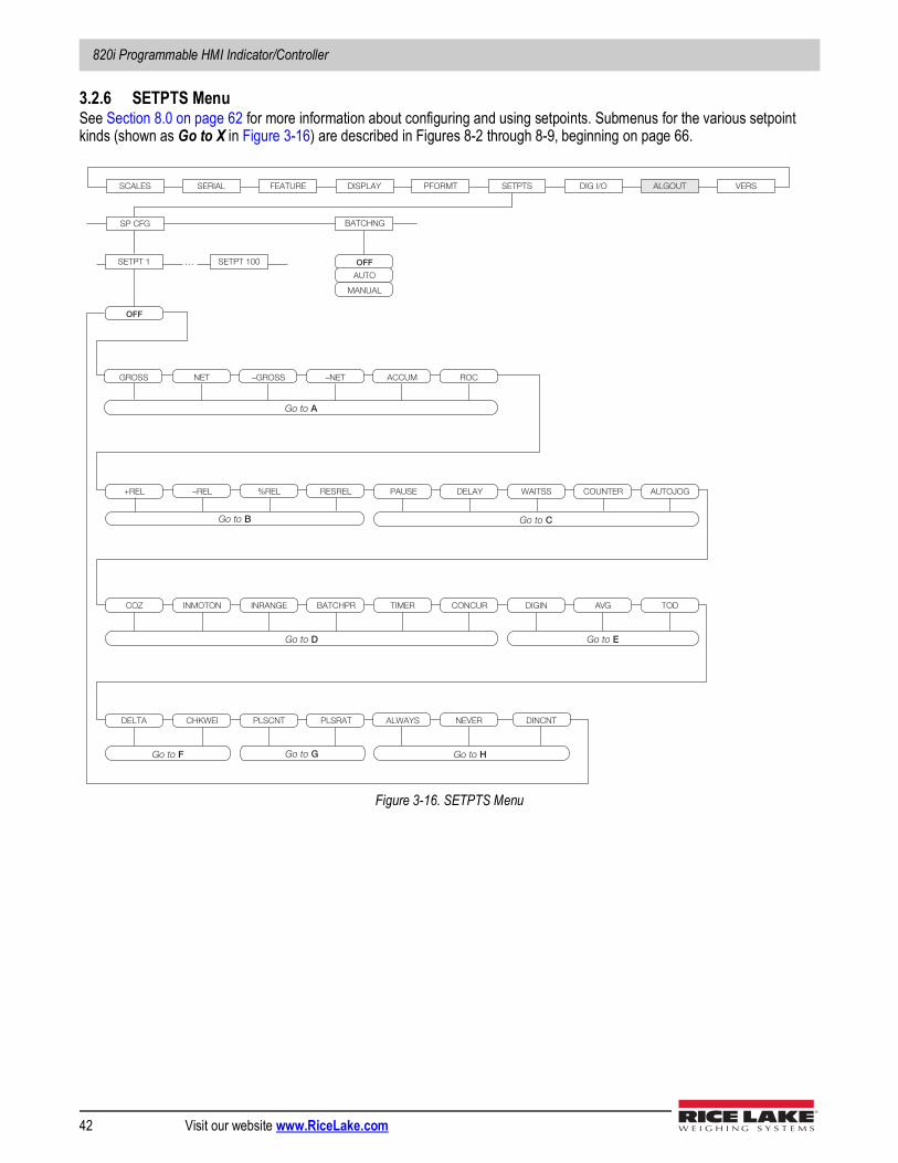
820i Programmable HMI Indicator/Controller
42 Visit our website www.RiceLake.com
3.2.6 SETPTS MenuSee Section 8.0 on page 62 for more information about configuring and using setpoints. Submenus for the various setpoint kinds (shown as Go to X in Figure 3-16) are described in Figures 8-2 through 8-9, beginning on page 66.
Figure 3-16. SETPTS Menu
SCALES SERIAL FEATURE PFORMT SETPTS DIG I/O ALGOUT VERS
SP CFG BATCHNG
OFF
MANUAL
AUTO
SETPT 1 SETPT 100 …
–NET ACCUM
OFF
NET GROSS –GROSS ROC
RESREL PAUSE –REL +REL %REL DELAY
COZ INMOTON
COUNTER WAITSS AUTOJOG
INRANGE DIGIN AVG TIMER BATCHPR CONCUR TOD
PLSRAT CHKWEI DELTA PLSCNT
Go to A
Go to B Go to C
Go to E
Go to F
Go to D
NEVER ALWAYS
Go to G
DINCNT
Go to H
DISPLAY
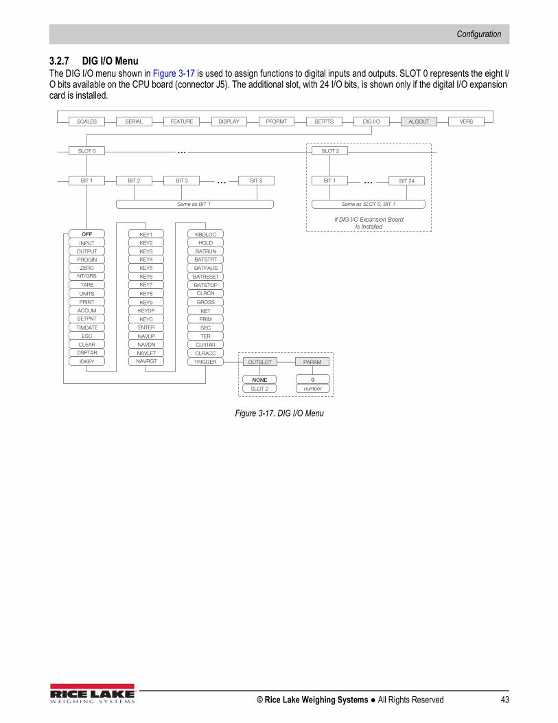
Configuration
© Rice Lake Weighing Systems ● All Rights Reserved 43
3.2.7 DIG I/O MenuThe DIG I/O menu shown in Figure 3-17 is used to assign functions to digital inputs and outputs. SLOT 0 represents the eight I/O bits available on the CPU board (connector J5). The additional slot, with 24 I/O bits, is shown only if the digital I/O expansion card is installed.
Figure 3-17. DIG I/O Menu
SCALES SERIAL FEATURE PFORMT SETPTS DIG I/O ALGOUT VERS
BIT 1
INPUT
OUTPUT
OFF
ZERO
NT/GRS
BIT 2
SLOT 0
BIT 3 BIT 8
UNITS
TARE
ACCUM
SETPNT
TIMDATE
ESC
CLEAR
DSPTAR
KEY1
KEY2
IDKEY
KEY3
KEY4
KEY5
KEY6
KEY7
KEY9
KEYDP
KEY8
KEY0
ENTER
KBDLOC
HOLD
BATRUN
BATSTRT
BATPAUS
BATRESET
CLRCN
NET
PRIM
GROSS
SEC
CLRTAR
CLRACC
Same as BIT 1
SLOT 2 …
PROGIN
NAVUP
NAVDN
NAVLFT
NAVRGT
TER
BIT 1 BIT 24
Same as SLOT 0, BIT 1
…
BATSTOP
TRIGGER OUTSLOT PARAM
NONE
SLOT 2
0
number
…
DISPLAY
If DIG I/O Expansion Board Is Installed
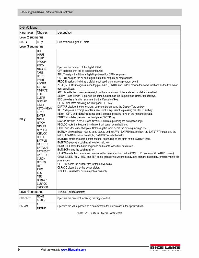
820i Programmable HMI Indicator/Controller
44 Visit our website www.RiceLake.com
DIG I/O MenuParameter Choices DescriptionLevel 2 submenusSLOTx BIT y Lists available digital I/O slots.Level 3 submenus
BIT y
OFFINPUTOUTPUTPROGINZERONT/GRSTAREUNITSPRINTACCUMSETPNTTIMDATEESCCLEARDSPTARIDKEYKEY0—KEY9KEYDPENTERNAVUPNAVDNNAVLFTNAVRGTKBDLOCHOLDBATRUNBATSTRTBATPAUSBATRESETBATSTOPCLRCNGROSSNETPRIMSECTERCLRTARCLRACCTRIGGER
Specifies the function of the digital I/O bit.OFF indicates that the bit is not configured.INPUT assigns the bit as a digital input used for DIGIN setpoints.OUTPUT assigns the bit as a digital output for setpoint or program use.PROGIN assigns the bit as a digital input used to generate a program event.ZERO, NT/GRS (net/gross mode toggle), TARE, UNITS, and PRINT provide the same functions as the five major front panel keys.ACCUM adds the current scale weight to the accumulator, if the scale accumulator is enabled.SETPNT, and TIMDATE provide the same functions as the Setpoint and Time/Date softkeys. ESC provides a function equivalent to the Cancel softkey.CLEAR simulates pressing the front panel CLR key.DSPTAR displays the current tare; equivalent to pressing the Display Tare softkey.IDKEY displays a prompt to enter a new unit ID; equivalent to pressing the Unit ID softkey.KEY0—KEY9 and KEYDP (decimal point) simulate pressing keys on the numeric keypad.ENTER simulates pressing the front panel ENTER key.NAVUP, NAVDN, NAVLFT, and NAVRGT simulate pressing the navigation keys.KBDLOC locks the keyboard (indicator front panel) when held low.HOLD holds the current display. Releasing this input clears the running average filter.BATRUN allows a batch routine to be started and run. With BATRUN active (low), the BATSTRT input starts the batch; if BATRUN is inactive (high), BATSTRT resets the batch.BATSTRT starts or resets a batch routine, depending on the state of the BATRUN input.BATPAUS pauses a batch routine when held low.BATRESET stops the batch sequence and resets to the first batch step.BATSTOP stops the batch routine.CLRCN resets the consecutive number to the value specified on the CONSTUP parameter (FEATURE menu).GROSS, NET, PRIM, SEC, and TER select gross or net weight display, and primary, secondary, or tertiary units dis-play modes.CLRTAR clears the current tare for the active scale.CLRACC clears the active accumulator.TRIGGER is used for custom applications only.
Level 4 submenus TRIGGER subparameters
OUTSLOT NONESLOT 2 Specifies the card slot receiving the trigger output.
PARAM 0number Specifies the value passed as a parameter to the option card in the specified slot.
Table 3-10. DIG I/O Menu Parameters
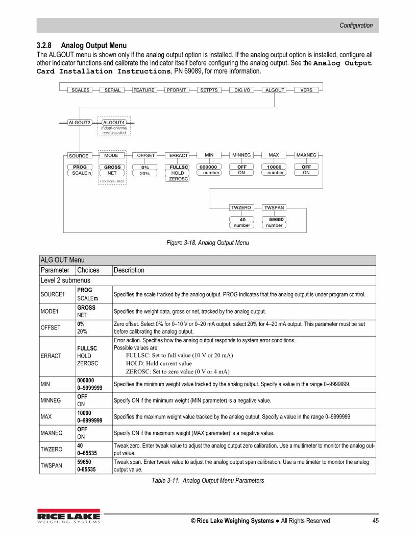
Configuration
© Rice Lake Weighing Systems ● All Rights Reserved 45
3.2.8 Analog Output MenuThe ALGOUT menu is shown only if the analog output option is installed. If the analog output option is installed, configure all other indicator functions and calibrate the indicator itself before configuring the analog output. See the Analog Output Card Installation Instructions, PN 69089, for more information.
Figure 3-18. Analog Output Menu
ALG OUT MenuParameter Choices DescriptionLevel 2 submenus
SOURCE1PROGSCALEn Specifies the scale tracked by the analog output. PROG indicates that the analog output is under program control.
MODE1 GROSSNET Specifies the weight data, gross or net, tracked by the analog output.
OFFSET 0%20%
Zero offset. Select 0% for 0–10 V or 0–20 mA output; select 20% for 4–20 mA output. This parameter must be set before calibrating the analog output.
ERRACTFULLSCHOLDZEROSC
Error action. Specifies how the analog output responds to system error conditions. Possible values are:
FULLSC: Set to full value (10 V or 20 mA)HOLD: Hold current valueZEROSC: Set to zero value (0 V or 4 mA)
MIN 0000000–9999999 Specifies the minimum weight value tracked by the analog output. Specify a value in the range 0–9999999.
MINNEG OFFON Specify ON if the minimum weight (MIN parameter) is a negative value.
MAX 100000–9999999 Specifies the maximum weight value tracked by the analog output. Specify a value in the range 0–9999999
MAXNEG OFFON Specify ON if the maximum weight (MAX parameter) is a negative value.
TWZERO 400–65535
Tweak zero. Enter tweak value to adjust the analog output zero calibration. Use a multimeter to monitor the analog out-put value.
TWSPAN 596500-65535
Tweak span. Enter tweak value to adjust the analog output span calibration. Use a multimeter to monitor the analog output value.
Table 3-11. Analog Output Menu Parameters
SCALES SERIAL FEATURE PFORMT SETPTS DIG I/O ALGOUT VERS
number40
number
SOURCE
PROG
OFFSET
20%0%
ERRACT
SCALE nFULLSCHOLD
ZEROSC
TWZERO
59650
TWSPAN
MODE
GROSSNET
If SOURCE1≠ PROG
ALGOUT2 ALGOUT4If dual-channelcard installed
number10000
ON
MIN
number000000
MINNEG
ONOFF
MAX
OFF
MAXNEG
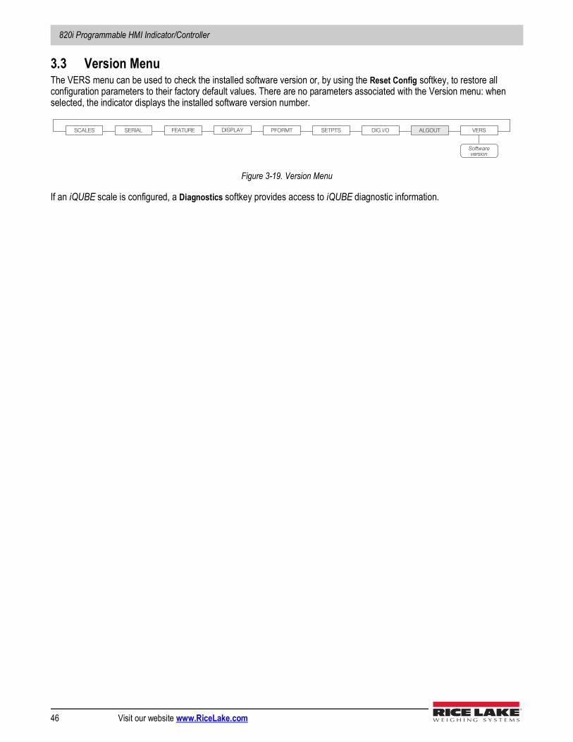
820i Programmable HMI Indicator/Controller
46 Visit our website www.RiceLake.com
3.3 Version MenuThe VERS menu can be used to check the installed software version or, by using the Reset Config softkey, to restore all configuration parameters to their factory default values. There are no parameters associated with the Version menu: when selected, the indicator displays the installed software version number.
Figure 3-19. Version Menu
If an iQUBE scale is configured, a Diagnostics softkey provides access to iQUBE diagnostic information.
SCALES SERIAL FEATURE PFORMT SETPTS DIG I/O ALGOUT VERS
Software version
DISPLAY
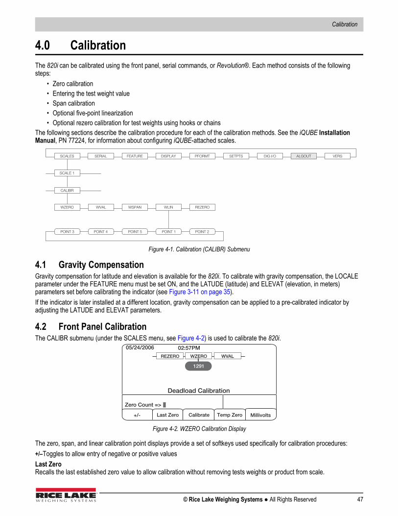
Calibration
© Rice Lake Weighing Systems ● All Rights Reserved 47
4.0 CalibrationThe 820i can be calibrated using the front panel, serial commands, or Revolution®. Each method consists of the following steps:
• Zero calibration• Entering the test weight value• Span calibration• Optional five-point linearization• Optional rezero calibration for test weights using hooks or chains
The following sections describe the calibration procedure for each of the calibration methods. See the iQUBE Installation Manual, PN 77224, for information about configuring iQUBE-attached scales.
Figure 4-1. Calibration (CALIBR) Submenu
4.1 Gravity CompensationGravity compensation for latitude and elevation is available for the 820i. To calibrate with gravity compensation, the LOCALE parameter under the FEATURE menu must be set ON, and the LATUDE (latitude) and ELEVAT (elevation, in meters) parameters set before calibrating the indicator (see Figure 3-11 on page 35).If the indicator is later installed at a different location, gravity compensation can be applied to a pre-calibrated indicator by adjusting the LATUDE and ELEVAT parameters.
4.2 Front Panel CalibrationThe CALIBR submenu (under the SCALES menu, see Figure 4-2) is used to calibrate the 820i.
Figure 4-2. WZERO Calibration Display
The zero, span, and linear calibration point displays provide a set of softkeys used specifically for calibration procedures:+/–Toggles to allow entry of negative or positive valuesLast ZeroRecalls the last established zero value to allow calibration without removing tests weights or product from scale.
SCALES SERIAL FEATURE PFORMT SETPTS DIG I/O ALGOUT VERS
SCALE 1
CALIBR
WZERO WVAL WSPAN WLIN REZERO
POINT 4 POINT 5 POINT 1 POINT 2 POINT 3
DISPLAY
05/24/2006 02:57PM
Calibrate
WZERO WVAL REZERO
1291
Deadload Calibration
+/- Millivolts
Zero Count =>
Last Zero Temp Zero
820i Programmable HMI Indicator/Controller
48 Visit our website www.RiceLake.com
CalibratePerforms calibration for the selected pointTemp Zero Temporarily zeroes the displayed weight of a non-empty scale. After span calibration, the difference between the temp zero and the previously calibrated zero value is used as an offset.Millivolts (or Counts)Toggles between display of captured A/D counts and captured millivolts values; allows entry of calibration values in mV or countsTo calibrate the indicator using the front panel, do the following:
1. Place the indicator in setup mode (display reads Scale Configuration) and remove all weight from the scale platform. If your test weights require hooks or chains, place the hooks or chains on the scale for zero calibration.
2. With the SCALES menu highlighted, press the down key, then select the scale to be calibrated. Press down again (GRADS parameter highlighted), then press left to highlight the CALIBR submenu (see Figure 4-1). Press down to go to zero calibration (WZERO). See Figure 4-2.
3. Ensure scale is empty, then press down again to show the current WZERO value, then press the Calibrate softkey to calibrate zero. When complete, the new A/D count for the zero calibration is displayed. Press enter to save the zero calibration value and go to the next prompt (WVAL).
4. With WVAL displayed, press down to show the stored calibration weight value. Use the numeric keypad to enter the actual value of the calibration test weights, then press enter to save the value and go to span calibration (WSPAN).
5. Place test weights on scale. Press down again to show the current WSPAN value, then press the Calibrate softkey to calibrate span. When complete, the new A/D count for the span calibration is displayed. Press enter again to save the span calibration value and go to the next prompt (WLIN).
6. Five-point linearization (using the WLIN parameter) provides increased scale accuracy by calibrating the indicator at up to five additional points between the zero and span calibrations. Linearization is optional: if you choose not to perform linearization, skip the WLIN parameter; if linearization values have previously been entered, these values are reset to zero during calibration. To perform linearization, follow the procedure below:With WLIN displayed, Press down to go to the first linearization point (POINT 1). Press down again to show the weight value prompt (WGT 1), then down once more to show the weight value. Place test weights on the scale, then use the numeric keypad to enter the actual test weight value. Press enter to save the value and move to the calibration (CAL 1) prompt. Press down to show the current calibration value, then press the Calibrate softkey to calibrate the linearization point. When complete, the A/D count for the linear calibration is displayed. Press enter again to save the calibration value and go to the next prompt (POINT 2).Repeat for up to five linearization points. To exit the linearization parameters, press the up key to return to WLIN.
7. The optional rezero function is used to remove a calibration offset when hooks or chains are used to hang the test weights.
The rezero function cannot be used with five-point linear calibration.
• If no other apparatus was used to hang the test weights during calibration, remove the test weights and press up to return to the CALIBR submenu.
• If hooks or chains were used during calibration, remove these and the test weights from the scale. With all weight removed, go to the REZERO parameter, then press down to show the current zero value. Press the Calibrate softkey to adjust the zero and span calibration values. Press enter or up to return to the CALIBR submenu.
8. Press up to return to the SCALES menu, or press the Save and Exit softkey to exit setup mode.
4.3 Serial Command CalibrationTo calibrate the indicator using serial commands, the indicator serial port must be connected to a terminal or personal computer. See Section 2.3.3 on page 10 for serial port pin assignments; see Section 9.0 on page 80 for more information about using serial commands.Once the indicator is connected to the sending device, do the following:
Note
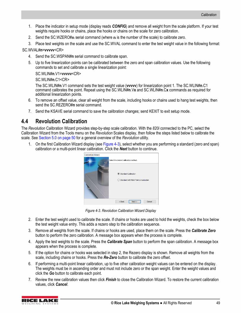
Calibration
© Rice Lake Weighing Systems ● All Rights Reserved 49
1. Place the indicator in setup mode (display reads CONFIG) and remove all weight from the scale platform. If your test weights require hooks or chains, place the hooks or chains on the scale for zero calibration.
2. Send the SC.WZERO#n serial command (where n is the number of the scale) to calibrate zero.3. Place test weights on the scale and use the SC.WVAL command to enter the test weight value in the following format:
SC.WVAL#n=vvvvv<CR> 4. Send the SC.WSPAN#n serial command to calibrate span.5. Up to five linearization points can be calibrated between the zero and span calibration values. Use the following
commands to set and calibrate a single linearization point:SC.WLIN#n.V1=vvvvv<CR> SC.WLIN#n.C1<CR>The SC.WLIN#n.V1 command sets the test weight value (vvvvv) for linearization point 1. The SC.WLIN#n.C1 command calibrates the point. Repeat using the SC.WLIN#n.Vx and SC.WLIN#n.Cx commands as required for additional linearization points.
6. To remove an offset value, clear all weight from the scale, including hooks or chains used to hang test weights, then send the SC.REZERO#n serial command.
7. Send the KSAVE serial command to save the calibration changes; send KEXIT to exit setup mode.
4.4 Revolution CalibrationThe Revolution Calibration Wizard provides step-by-step scale calibration. With the 820i connected to the PC, select the Calibration Wizard from the Tools menu on the Revolution Scales display, then follow the steps listed below to calibrate the scale. See Section 5.0 on page 50 for a general overview of the Revolution utility.
1. On the first Calibration Wizard display (see Figure 4-3), select whether you are performing a standard (zero and span) calibration or a multi-point linear calibration. Click the Next button to continue.
Figure 4-3. Revolution Calibration Wizard Display
2. Enter the test weight used to calibrate the scale. If chains or hooks are used to hold the weights, check the box below the test weight value entry. This adds a rezero step to the calibration sequence.
3. Remove all weights from the scale. If chains or hooks are used, place them on the scale. Press the Calibrate Zero button to perform the zero calibration. A message box appears when the process is complete.
4. Apply the test weights to the scale. Press the Calibrate Span button to perform the span calibration. A message box appears when the process is complete.
5. If the option for chains or hooks was selected in step 2, the Rezero display is shown. Remove all weights from the scale, including chains or hooks. Press the Re-Zero button to calibrate the zero offset.
6. If performing a multi-point linear calibration, up to five other calibration weight values can be entered on the display. The weights must be in ascending order and must not include zero or the span weight. Enter the weight values and click the Go button to calibrate each point.
7. Review the new calibration values then click Finish to close the Calibration Wizard. To restore the current calibration values, click Cancel.
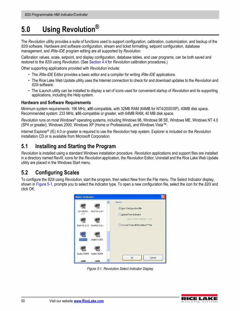
820i Programmable HMI Indicator/Controller
50 Visit our website www.RiceLake.com
5.0 Using Revolution®
The Revolution utility provides a suite of functions used to support configuration, calibration, customization, and backup of the 820i software. Hardware and software configuration, stream and ticket formatting, setpoint configuration, database management, and iRite-IDE program editing are all supported by Revolution. Calibration values, scale, setpoint, and display configuration, database tables, and user programs, can be both saved and restored to the 820i using Revolution. (See Section 4.4 for Revolution calibration procedures.) Other supporting applications provided with Revolution include:
• The iRite-IDE Editor provides a basic editor and a compiler for writing iRite-IDE applications.• The Rice Lake Web Update utility uses the Internet connection to check for and download updates to the Revolution and
820i software.• The iLaunch utility can be installed to display a set of icons used for convenient startup of Revolution and its supporting
applications, including the Help system.
Hardware and Software RequirementsMinimum system requirements: 166 MHz, x86-compatible, with 32MB RAM (64MB for NT4/2000/XP), 40MB disk space. Recommended system: 233 MHz, x86-compatible or greater, with 64MB RAM, 40 MB disk space.Revolution runs on most Windows® operating systems, including Windows 98, Windows 98 SE, Windows ME, Windows NT 4.0 (SP4 or greater), Windows 2000, Windows XP (Home or Professional), and Windows Vista™.Internet Explorer® (IE) 4.0 or greater is required to use the Revolution help system. Explorer is included on the Revolution installation CD or is available from Microsoft Corporation.
5.1 Installing and Starting the ProgramRevolution is installed using a standard Windows installation procedure. Revolution applications and support files are installed in a directory named RevIII; icons for the Revolution application, the Revolution Editor, Uninstall and the Rice Lake Web Update utility are placed in the Windows Start menu.
5.2 Configuring ScalesTo configure the 820i using Revolution, start the program, then select New from the File menu. The Select Indicator display, shown in Figure 5-1, prompts you to select the indicator type. To open a new configuration file, select the icon for the 820i and click OK.
Figure 5-1. Revolution Select Indicator Display
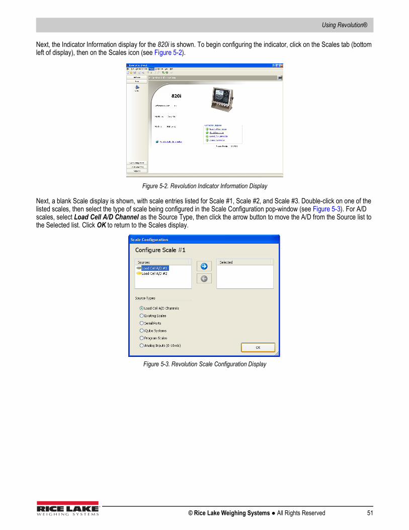
Using Revolution®
© Rice Lake Weighing Systems ● All Rights Reserved 51
Next, the Indicator Information display for the 820i is shown. To begin configuring the indicator, click on the Scales tab (bottom left of display), then on the Scales icon (see Figure 5-2).
Figure 5-2. Revolution Indicator Information Display
Next, a blank Scale display is shown, with scale entries listed for Scale #1, Scale #2, and Scale #3. Double-click on one of the listed scales, then select the type of scale being configured in the Scale Configuration pop-window (see Figure 5-3). For A/D scales, select Load Cell A/D Channel as the Source Type, then click the arrow button to move the A/D from the Source list to the Selected list. Click OK to return to the Scales display.
Figure 5-3. Revolution Scale Configuration Display
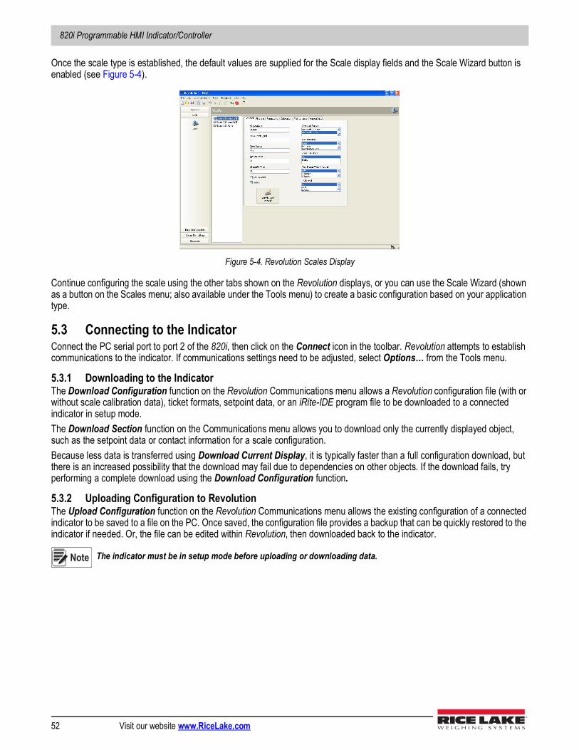
820i Programmable HMI Indicator/Controller
52 Visit our website www.RiceLake.com
Once the scale type is established, the default values are supplied for the Scale display fields and the Scale Wizard button is enabled (see Figure 5-4).
Figure 5-4. Revolution Scales Display
Continue configuring the scale using the other tabs shown on the Revolution displays, or you can use the Scale Wizard (shown as a button on the Scales menu; also available under the Tools menu) to create a basic configuration based on your application type.
5.3 Connecting to the IndicatorConnect the PC serial port to port 2 of the 820i, then click on the Connect icon in the toolbar. Revolution attempts to establish communications to the indicator. If communications settings need to be adjusted, select Options… from the Tools menu.
5.3.1 Downloading to the IndicatorThe Download Configuration function on the Revolution Communications menu allows a Revolution configuration file (with or without scale calibration data), ticket formats, setpoint data, or an iRite-IDE program file to be downloaded to a connected indicator in setup mode.The Download Section function on the Communications menu allows you to download only the currently displayed object, such as the setpoint data or contact information for a scale configuration.Because less data is transferred using Download Current Display, it is typically faster than a full configuration download, but there is an increased possibility that the download may fail due to dependencies on other objects. If the download fails, try performing a complete download using the Download Configuration function.
5.3.2 Uploading Configuration to RevolutionThe Upload Configuration function on the Revolution Communications menu allows the existing configuration of a connected indicator to be saved to a file on the PC. Once saved, the configuration file provides a backup that can be quickly restored to the indicator if needed. Or, the file can be edited within Revolution, then downloaded back to the indicator.
The indicator must be in setup mode before uploading or downloading data.Note
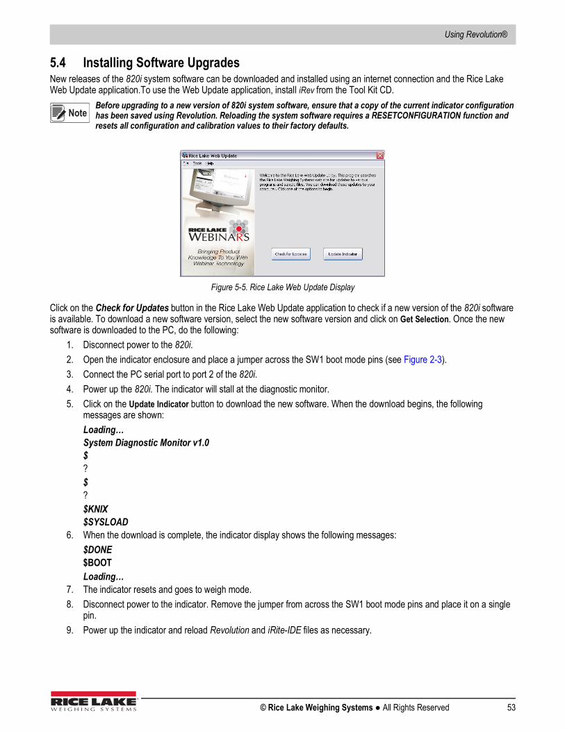
Using Revolution®
© Rice Lake Weighing Systems ● All Rights Reserved 53
5.4 Installing Software UpgradesNew releases of the 820i system software can be downloaded and installed using an internet connection and the Rice Lake Web Update application.To use the Web Update application, install iRev from the Tool Kit CD.
Before upgrading to a new version of 820i system software, ensure that a copy of the current indicator configuration has been saved using Revolution. Reloading the system software requires a RESETCONFIGURATION function and resets all configuration and calibration values to their factory defaults.
Figure 5-5. Rice Lake Web Update Display
Click on the Check for Updates button in the Rice Lake Web Update application to check if a new version of the 820i software is available. To download a new software version, select the new software version and click on Get Selection. Once the new software is downloaded to the PC, do the following:
1. Disconnect power to the 820i. 2. Open the indicator enclosure and place a jumper across the SW1 boot mode pins (see Figure 2-3). 3. Connect the PC serial port to port 2 of the 820i. 4. Power up the 820i. The indicator will stall at the diagnostic monitor.5. Click on the Update Indicator button to download the new software. When the download begins, the following
messages are shown:Loading…System Diagnostic Monitor v1.0$?$?$KNIX$SYSLOAD
6. When the download is complete, the indicator display shows the following messages:$DONE$BOOTLoading…
7. The indicator resets and goes to weigh mode. 8. Disconnect power to the indicator. Remove the jumper from across the SW1 boot mode pins and place it on a single
pin.9. Power up the indicator and reload Revolution and iRite-IDE files as necessary.
Note
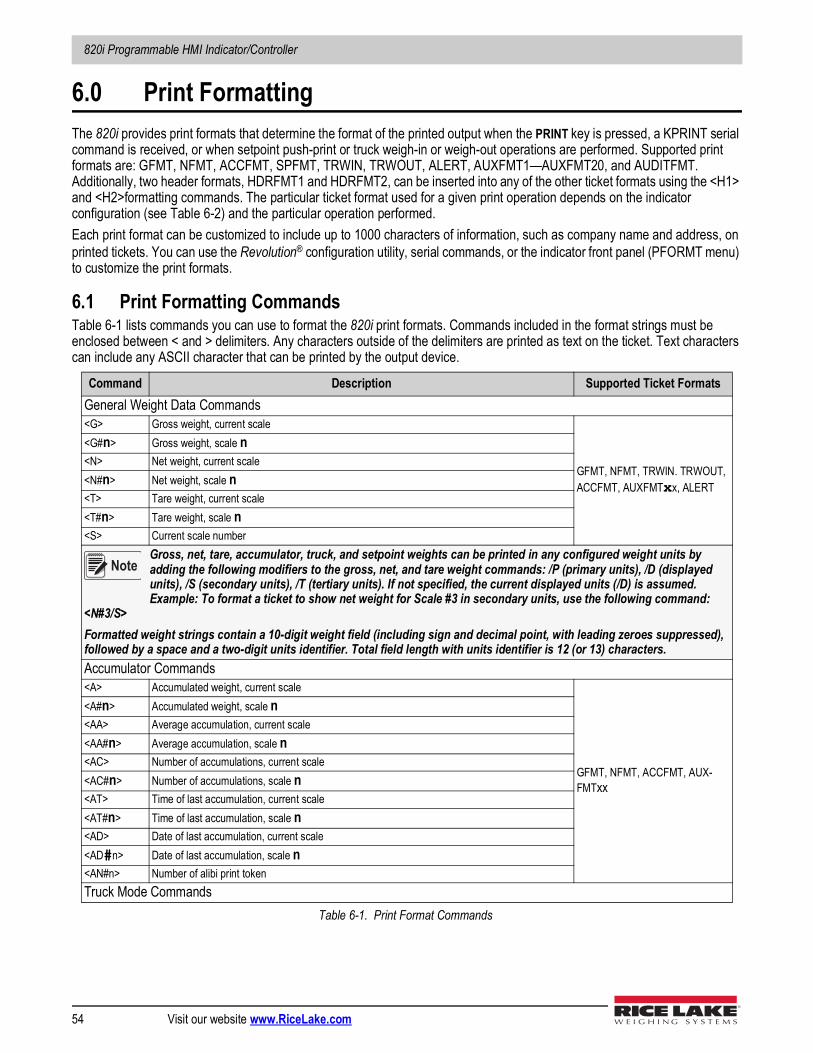
820i Programmable HMI Indicator/Controller
54 Visit our website www.RiceLake.com
6.0 Print FormattingThe 820i provides print formats that determine the format of the printed output when the PRINT key is pressed, a KPRINT serial command is received, or when setpoint push-print or truck weigh-in or weigh-out operations are performed. Supported print formats are: GFMT, NFMT, ACCFMT, SPFMT, TRWIN, TRWOUT, ALERT, AUXFMT1—AUXFMT20, and AUDITFMT. Additionally, two header formats, HDRFMT1 and HDRFMT2, can be inserted into any of the other ticket formats using the <H1> and <H2>formatting commands. The particular ticket format used for a given print operation depends on the indicator configuration (see Table 6-2) and the particular operation performed.Each print format can be customized to include up to 1000 characters of information, such as company name and address, on printed tickets. You can use the Revolution® configuration utility, serial commands, or the indicator front panel (PFORMT menu) to customize the print formats.
6.1 Print Formatting CommandsTable 6-1 lists commands you can use to format the 820i print formats. Commands included in the format strings must be enclosed between < and > delimiters. Any characters outside of the delimiters are printed as text on the ticket. Text characters can include any ASCII character that can be printed by the output device.
Command Description Supported Ticket FormatsGeneral Weight Data Commands<G> Gross weight, current scale
GFMT, NFMT, TRWIN. TRWOUT, ACCFMT, AUXFMTxx, ALERT
<G#n> Gross weight, scale n<N> Net weight, current scale<N#n> Net weight, scale n<T> Tare weight, current scale<T#n> Tare weight, scale n<S> Current scale number
Gross, net, tare, accumulator, truck, and setpoint weights can be printed in any configured weight units by adding the following modifiers to the gross, net, and tare weight commands: /P (primary units), /D (displayed units), /S (secondary units), /T (tertiary units). If not specified, the current displayed units (/D) is assumed. Example: To format a ticket to show net weight for Scale #3 in secondary units, use the following command:
<N#3/S>Formatted weight strings contain a 10-digit weight field (including sign and decimal point, with leading zeroes suppressed), followed by a space and a two-digit units identifier. Total field length with units identifier is 12 (or 13) characters.Accumulator Commands<A> Accumulated weight, current scale
GFMT, NFMT, ACCFMT, AUX-FMTxx
<A#n> Accumulated weight, scale n<AA> Average accumulation, current scale<AA#n> Average accumulation, scale n<AC> Number of accumulations, current scale<AC#n> Number of accumulations, scale n<AT> Time of last accumulation, current scale<AT#n> Time of last accumulation, scale n<AD> Date of last accumulation, current scale<AD#n> Date of last accumulation, scale n<AN#n> Number of alibi print tokenTruck Mode Commands
Table 6-1. Print Format Commands
Note
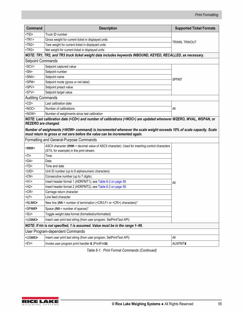
Print Formatting
© Rice Lake Weighing Systems ● All Rights Reserved 55
<TID> Truck ID number
TRWIN, TRWOUT<TR1> Gross weight for current ticket in displayed units<TR2> Tare weight for current ticket in displayed units<TR3> Net weight for current ticket in displayed unitsNOTE: TR1, TR2, and TR3 truck ticket weight data includes keywords INBOUND, KEYED, RECALLED, as necessary.Setpoint Commands<SCV> Setpoint captured value
SPFMT
<SN> Setpoint number<SNA> Setpoint name<SPM> Setpoint mode (gross or net label)<SPV> Setpoint preact value<STV> Setpoint target valueAuditing Commands<CD> Last calibration date
All<NOC> Number of calibrations<NOW> Number of weighments since last calibrationNOTE: Last calibration date (<CD>) and number of calibrations (<NOC>) are updated whenever WZERO, WVAL, WSPAN, or REZERO are changed.Number of weighments (<NOW> command) is incremented whenever the scale weight exceeds 10% of scale capacity. Scale must return to gross or net zero before the value can be incremented again.Formatting and General-Purpose Commands
<nnn> ASCII character (nnn = decimal value of ASCII character). Used for inserting control characters (STX, for example) in the print stream.
All
<TI> Time<DA> Date<TD> Time and date<UID> Unit ID number (up to 8 alphanumeric characters)<CN> Consecutive number (up to 7 digits)<H1> Insert header format 1 (HDRFMT1); see Table 6-2 on page 56<H2> Insert header format 2 (HDRFMT2); see Table 6-2 on page 56<CR> Carriage return character<LF> Line feed character<NLnn> New line (nn = number of termination (<CR/LF> or <CR>) characters)*<SPnn> Space (nn = number of spaces)*<SU> Toggle weight data format (formatted/unformatted)<USnn> Insert user print text string (from user program, SetPrintText API)NOTE: If nn is not specified, 1 is assumed. Value must be in the range 1–99.User Program-dependent Commands<USnn> Insert user print text string (from user program, SetPrintText API) All<EV> Invoke user program print handler x (PrintFmtx) AUXFMTx
Command Description Supported Ticket Formats
Table 6-1. Print Format Commands (Continued)
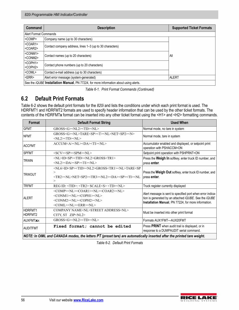
820i Programmable HMI Indicator/Controller
56 Visit our website www.RiceLake.com
6.2 Default Print FormatsTable 6-2 shows the default print formats for the 820i and lists the conditions under which each print format is used. The HDRFMT1 and HDRFMT2 formats are used to specify header information that can be used by the other ticket formats. The contents of the HDRFMTx format can be inserted into any other ticket format using the <H1> and <H2> formatting commands.
Alert Format Commands<COMP> Company name (up to 30 characters)
All
<COAR1><COAR2> Contact company address, lines 1–3 (up to 30 characters)
<CONM1><CONM2> Contact names (up to 20 characters)
<COPH1><COPH2> Contact phone numbers (up to 20 characters)
<COML> Contact e-mail address (up to 30 characters)<ERR> Alert error message (system-generated) ALERTSee the iQUBE Installation Manual, PN 77224, for more information about using alerts.
Format Default Format String Used WhenGFMT GROSS<G><NL2><TD><NL> Normal mode, no tare in system
NFMT GROSS<G><NL>TARE<SP><T><NL>NET<SP2><N><NL2><TD><NL>
Normal mode, tare in system
ACCFMT ACCUM<A><NL><DA><TI><NL> Accumulator enabled and displayed, or setpoint print operation with PSHACCM=ON
SPFMT <SCV><SP><SPM><NL> Setpoint print operation with PSHPRNT=ON
TRWIN<NL>ID<SP><TID><NL2>GROSS<TR1><NL2><DA><SP><TI><NL>
Press the Weigh In softkey, enter truck ID number, and press enter.
TRWOUT
<NL6>ID<SP><TID><NL2>GROSS<TR1><NL>TARE<SP><TR2><NL>NET<SP2><TR3><NL2><DA><SP><TI><NL>
Press the Weigh Out softkey, enter truck ID number, and press enter.
TRFMT REG ID: <TID>: <TR2> SCALE<S> <TD><NL> Truck register currently displayed
ALERT
<COMP><NL><COAR1><NL><COAR2><NL><CONM1><NL><COPH1><NL><CONM2><NL><COPH2><NL><COML><NL><ERR><NL>
Alert message is sent to specified port when error indica-tion is generated by an attached iQUBE. See the iQUBE Installation Manual, PN 77224, for more information.
HDRFMT1HDRFMT2
COMPANY NAME<NL>STREET ADDRESS<NL>CITY, ST ZIP<NL2>
Must be inserted into other print format
AUXFMTxx GROSS<G><NL2><TD><NL> Formats AUX1FMT—AUX20FMT
AUDITFMT Fixed format; cannot be edited Press PRINT when audit trail is displayed, or in response to a DUMPAUDIT serial command.
NOTE: In OIML and CANADA modes, the letters PT (preset tare) are automatically inserted after the printed tare weight.Table 6-2. Default Print Formats
Command Description Supported Ticket Formats
Table 6-1. Print Format Commands (Continued)
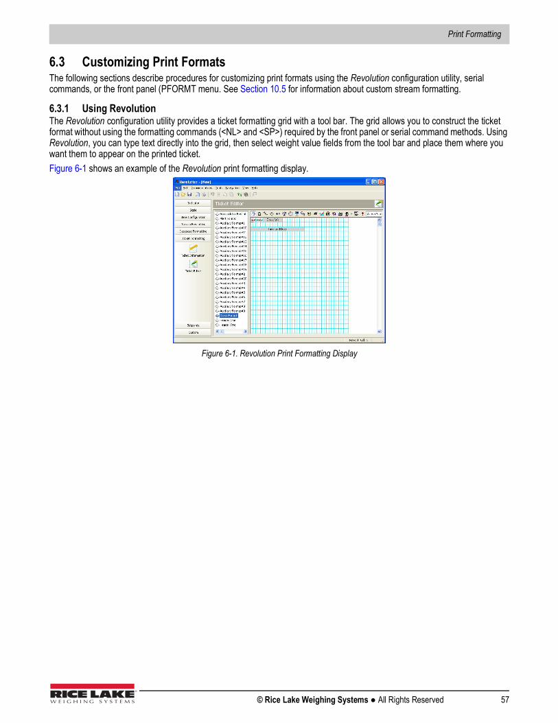
Print Formatting
© Rice Lake Weighing Systems ● All Rights Reserved 57
6.3 Customizing Print FormatsThe following sections describe procedures for customizing print formats using the Revolution configuration utility, serial commands, or the front panel (PFORMT menu. See Section 10.5 for information about custom stream formatting.
6.3.1 Using RevolutionThe Revolution configuration utility provides a ticket formatting grid with a tool bar. The grid allows you to construct the ticket format without using the formatting commands (<NL> and <SP>) required by the front panel or serial command methods. Using Revolution, you can type text directly into the grid, then select weight value fields from the tool bar and place them where you want them to appear on the printed ticket.Figure 6-1 shows an example of the Revolution print formatting display.
Figure 6-1. Revolution Print Formatting Display
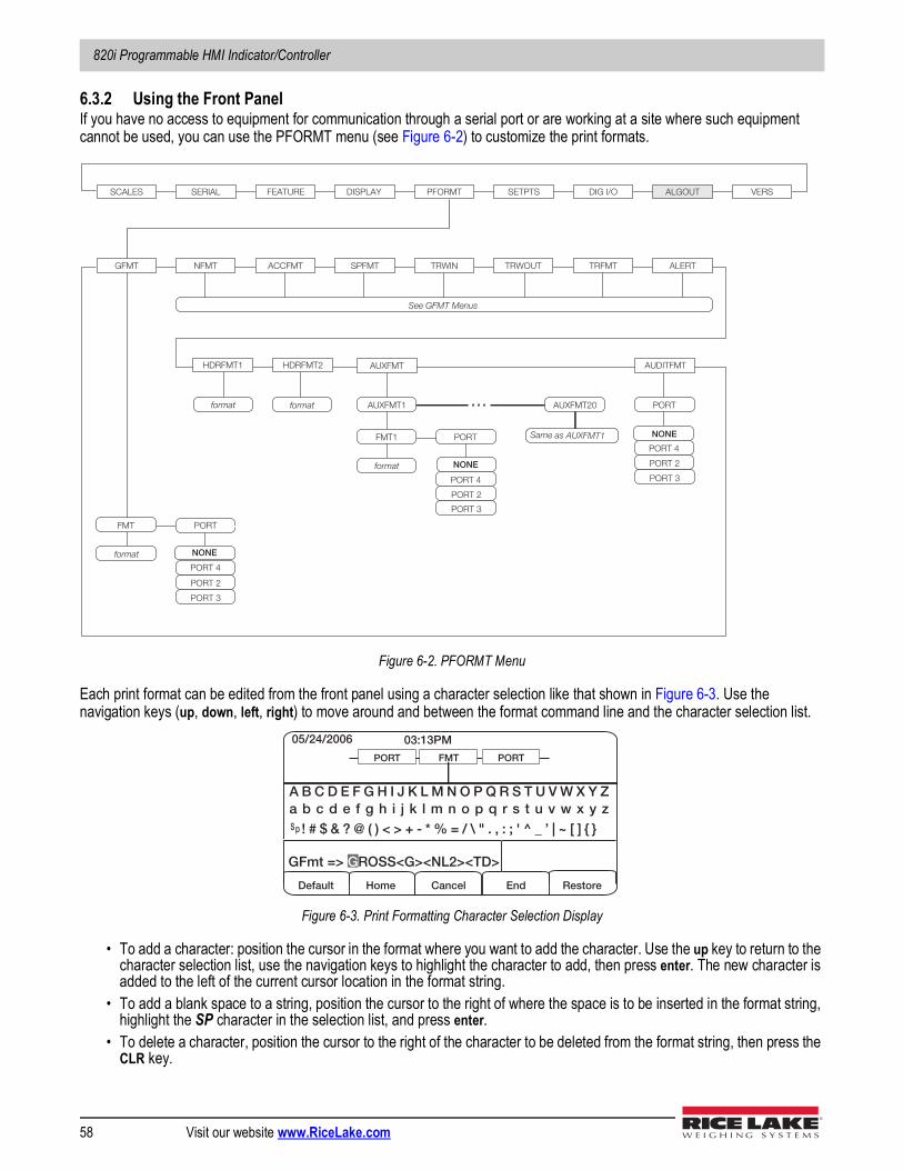
820i Programmable HMI Indicator/Controller
58 Visit our website www.RiceLake.com
6.3.2 Using the Front PanelIf you have no access to equipment for communication through a serial port or are working at a site where such equipment cannot be used, you can use the PFORMT menu (see Figure 6-2) to customize the print formats.
Figure 6-2. PFORMT Menu
Each print format can be edited from the front panel using a character selection like that shown in Figure 6-3. Use the navigation keys (up, down, left, right) to move around and between the format command line and the character selection list.
Figure 6-3. Print Formatting Character Selection Display
• To add a character: position the cursor in the format where you want to add the character. Use the up key to return to the character selection list, use the navigation keys to highlight the character to add, then press enter. The new character is added to the left of the current cursor location in the format string.
• To add a blank space to a string, position the cursor to the right of where the space is to be inserted in the format string, highlight the SP character in the selection list, and press enter.
• To delete a character, position the cursor to the right of the character to be deleted from the format string, then press the CLR key.
SCALES SERIAL FEATURE PFORMT SETPTS DIG I/O ALGOUT VERS
GFMT NFMT ACCFMT SPFMT TRWIN TRWOUT TRFMT
See GFMT Menus
PORTFMT
format
HDRFMT1 HDRFMT2 AUXFMT
format format
ALERT
Same as AUXFMT1
SERV
Alert emailserver
PHONE
Alert modemphone
ALERT format ONLY
AUDITFMT
PORTAUXFMT1 AUXFMT20
PORTFMT1
format
...
DISPLAY
PORT 2
PORT 4
PORT 3
PORT 2
PORT 4
PORT 3
PORT 2
PORT 4
PORT 3
NONE
NONE
NONE
05/24/2006 03:13PM
Cancel
FMT PORT PORT
Default Restore
GFmt => GROSS<G><NL2><TD>
Home End
A B C D E F G H I J K L M N O P Q R S T U V W X Y Z a b c d e f g h i j k l m n o p q r s t u v w x y z
! # $ & ? @ ( ) < > + - * % = / \ " . , : ; ' ^ _ ’ | ~ [ ] { } S p
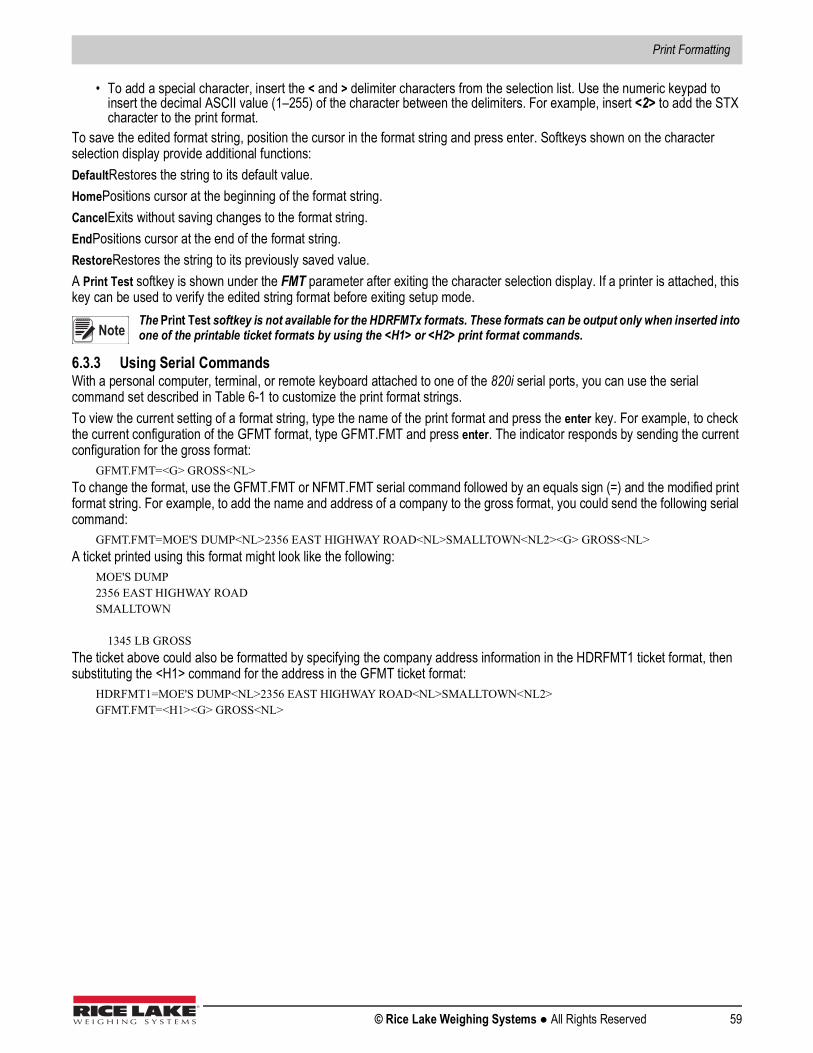
Print Formatting
© Rice Lake Weighing Systems ● All Rights Reserved 59
• To add a special character, insert the < and > delimiter characters from the selection list. Use the numeric keypad to insert the decimal ASCII value (1–255) of the character between the delimiters. For example, insert <2> to add the STX character to the print format.
To save the edited format string, position the cursor in the format string and press enter. Softkeys shown on the character selection display provide additional functions:DefaultRestores the string to its default value.HomePositions cursor at the beginning of the format string.CancelExits without saving changes to the format string.EndPositions cursor at the end of the format string.RestoreRestores the string to its previously saved value.A Print Test softkey is shown under the FMT parameter after exiting the character selection display. If a printer is attached, this key can be used to verify the edited string format before exiting setup mode.
The Print Test softkey is not available for the HDRFMTx formats. These formats can be output only when inserted into one of the printable ticket formats by using the <H1> or <H2> print format commands.
6.3.3 Using Serial CommandsWith a personal computer, terminal, or remote keyboard attached to one of the 820i serial ports, you can use the serial command set described in Table 6-1 to customize the print format strings. To view the current setting of a format string, type the name of the print format and press the enter key. For example, to check the current configuration of the GFMT format, type GFMT.FMT and press enter. The indicator responds by sending the current configuration for the gross format:
GFMT.FMT=<G> GROSS<NL>To change the format, use the GFMT.FMT or NFMT.FMT serial command followed by an equals sign (=) and the modified print format string. For example, to add the name and address of a company to the gross format, you could send the following serial command:
GFMT.FMT=MOE'S DUMP<NL>2356 EAST HIGHWAY ROAD<NL>SMALLTOWN<NL2><G> GROSS<NL>A ticket printed using this format might look like the following:
MOE'S DUMP2356 EAST HIGHWAY ROADSMALLTOWN
1345 LB GROSSThe ticket above could also be formatted by specifying the company address information in the HDRFMT1 ticket format, then substituting the <H1> command for the address in the GFMT ticket format:
HDRFMT1=MOE'S DUMP<NL>2356 EAST HIGHWAY ROAD<NL>SMALLTOWN<NL2>GFMT.FMT=<H1><G> GROSS<NL>
Note

820i Programmable HMI Indicator/Controller
60 Visit our website www.RiceLake.com
7.0 Truck ModesThe truck in/out modes are used to handle multiple truck ID numbers and weights. Truck IDs can be up to 16 alphanumeric characters in length.Six truck modes combine stored ID, keyed tare, and value swapping features in various ways:
Stored IDs let you keep a database of truck IDs and weigh-in weights in the indicator’s memory. The indicator can automatically store up to 1000 truck IDs and tares; or it can clear the information after printing a weigh-out ticket. For example, if the same truck seldom crosses the scale, it may not be practical to save its ID number and weigh-in weight. However, if that same truck crosses the scale many times each day, it’s more convenient to store the information in the indicator memory and recall it when needed. Stored IDs and weights are available in modes 3, 4, 5, and 6.Keyed tares allow you to manually enter the tare weight using the numeric keypad and the TARE key. Keyed tares are available in modes 1, 3, and 5. To use keyed tares, an incoming truck must be empty at weigh-in, full at weigh-out.
Some local regulations require the tare weight to be read from the scale. If so, don’t use the keyed tares feature.
Value swapping ensures that the lowest of two weight values associated with a particular ID number is used as the tare weight. For example, if a truck crosses the scale fully loaded at weigh-in, then unloads and crosses the scale empty at weigh-out, the indicator automatically assigns the lesser (empty truck) weight as the tare. Value swapping is available in modes 1, 2, 3, and 4.
7.1 Using the Truck ModesTo select a truck in/out mode, press the setup switch to enter setup mode. Use the navigation keys to go to the FEATURE menu, then to the TRUCK submenu to select the mode.Next, go right to the SOFTKEYS submenu and configure the Weigh In, Weigh Out, and Truck Regs softkeys. These keys are required when using the truck modes.
Figure 7-1. 820i Display, showing Truck Mode Softkeys
Mode Stored IDs Keyed TaresValue
SwappingMODE1 NO YES YESMODE2 NO NO YESMODE3 YES YES YESMODE4 YES NO YESMODE5 YES YES NOMODE6 YES NO NO
OFF
Truck Mode Features
Note
05/25/2006 08:01PM
12500 Scale #1
lb Gross
Weigh In Weigh Out Truck Regs
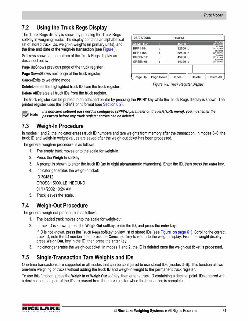
Truck Modes
© Rice Lake Weighing Systems ● All Rights Reserved 61
7.2 Using the Truck Regs DisplayThe Truck Regs display is shown by pressing the Truck Regs softkey in weighing mode. The display contains an alphabetical list of stored truck IDs, weigh-in weights (in primary units), and the time and date of the weigh-in transaction (see Figure ).Softkeys shown at the bottom of the Truck Regs display are described below. Page UpShows previous page of the truck register.Page DownShows next page of the truck register.CancelExits to weighing mode.DeleteDeletes the highlighted truck ID from the truck register.Delete AllDeletes all truck IDs from the truck register.The truck register can be printed to an attached printer by pressing the PRINT key while the Truck Regs display is shown. The printed register uses the TRFMT print format (see Section 6.2).
If a non-zero setpoint password is configured (SPPWD parameter on the FEATURE menu), you must enter the password before any truck register entries can be deleted.
7.3 Weigh-In ProcedureIn modes 1 and 2, the indicator erases truck ID numbers and tare weights from memory after the transaction. In modes 3–6, the truck ID and weigh-in weight values are saved after the weigh-out ticket has been processed.The general weigh-in procedure is as follows:
1. The empty truck moves onto the scale for weigh-in.2. Press the Weigh In softkey.3. A prompt is shown to enter the truck ID (up to eight alphanumeric characters). Enter the ID, then press the enter key.4. Indicator generates the weigh-in ticket:
ID 304812GROSS 15000. LB INBOUND01/14/2002 10:24 AM
5. Truck leaves the scale.
7.4 Weigh-Out ProcedureThe general weigh-out procedure is as follows:
1. The loaded truck moves onto the scale for weigh-out. 2. If truck ID is known, press the Weigh Out softkey, enter the ID, and press the enter key.
If ID is not known, press the Truck Regs softkey to view list of stored IDs (see Figure on page 61). Scroll to the correct truck ID, note the ID number, then press the Cancel softkey to return to the weight display. From the weight display, press Weigh Out, key in the ID, then press the enter key.
3. Indicator generates the weigh-out ticket. In modes 1 and 2, the ID is deleted once the weigh-out ticket is processed.
7.5 Single-Transaction Tare Weights and IDsOne-time transactions are supported in all modes that can be configured to use stored IDs (modes 3–6). This function allows one-time weighing of trucks without adding the truck ID and weigh-in weight to the permanent truck register.To use this function, press the Weigh In or Weigh Out softkey, then enter a truck ID containing a decimal point. IDs entered with a decimal point as part of the ID are erased from the truck register when the transaction is complete.
05/25/2006 08:04PM
Page Up Cancel Delete All Page Down Delete
ACME 152 : 45260 lb BRF 1454 : 32500 lb BRF 1468 : 32500 lb GREEN 12 : 45260 lb GREEN 66 : 44220 lb
03:20PM 05/17/2006
05:18PM 05/18/2006
05:29PM 05/18/2006
08:06AM 05/18/2006
10:24AM 05/18/2006
Figure 7-2. Truck Register Display
Note
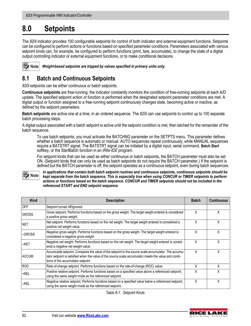
820i Programmable HMI Indicator/Controller
62 Visit our website www.RiceLake.com
8.0 SetpointsThe 820i indicator provides 100 configurable setpoints for control of both indicator and external equipment functions. Setpoints can be configured to perform actions or functions based on specified parameter conditions. Parameters associated with various setpoint kinds can, for example, be configured to perform functions (print, tare, accumulate), to change the state of a digital output controlling indicator or external equipment functions, or to make conditional decisions.
Weight-based setpoints are tripped by values specified in primary units only.
8.1 Batch and Continuous Setpoints820i setpoints can be either continuous or batch setpoints.Continuous setpoints are free-running: the indicator constantly monitors the condition of free-running setpoints at each A/D update. The specified setpoint action or function is performed when the designated setpoint parameter conditions are met. A digital output or function assigned to a free-running setpoint continuously changes state, becoming active or inactive, as defined by the setpoint parameters. Batch setpoints are active one at a time, in an ordered sequence. The 820i can use setpoints to control up to 100 separate batch processing steps. A digital output associated with a batch setpoint is active until the setpoint condition is met, then latched for the remainder of the batch sequence.
To use batch setpoints, you must activate the BATCHNG parameter on the SETPTS menu. This parameter defines whether a batch sequence is automatic or manual. AUTO sequences repeat continuously, while MANUAL sequences require a BATSTRT signal. The BATSTRT signal can be initiated by a digital input, serial command, Batch Start softkey, or the StartBatch function in an iRite-IDE program.For setpoint kinds that can be used as either continuous or batch setpoints, the BATCH parameter must also be set ON. (Setpoint kinds that can only be used as batch setpoints do not require the BATCH parameter.) If the setpoint is defined but the BATCH parameter is off, the setpoint operates as a continuous setpoint, even during batch sequences.
In applications that contain both batch setpoint routines and continuous setpoints, continuous setpoints should be kept separate from the batch sequence. This is especially true when using CONCUR or TIMER setpoints to perform actions or functions based on the batch sequence. CONCUR and TIMER setpoints should not be included in the referenced START and END setpoint sequence.
Kind Description Batch ContinuousOFF Setpoint turned off/ignored.
GROSS Gross setpoint. Performs functions based on the gross weight. The target weight entered is considered a positive gross weight.
X X
NET Net setpoint. Performs functions based on the net weight. The target weight entered is considered a positive net weight value.
X X
–GROSS Negative gross weight. Performs functions based on the gross weight. The target weight entered is considered a negative gross weight.
X X
–NET Negative net weight. Performs functions based on the net weight. The target weight entered is consid-ered a negative net weight value.
X X
ACCUMAccumulate setpoint. Compares the value of the setpoint to the source scale accumulator. The accumu-lator setpoint is satisfied when the value of the source scale accumulator meets the value and condi-tions of the accumulator setpoint.
X X
ROC Rate-of-change setpoint. Performs functions based on the rate-of-change (ROC) value. X X
+REL Positive relative setpoint. Performs functions based on a specified value above a referenced setpoint, using the same weight mode as the referenced setpoint.
X X
–REL Negative relative setpoint. Performs functions based on a specified value below a referenced setpoint, using the same weight mode as the referenced setpoint.
X X
Table 8-1. Setpoint Kinds
Note
Note
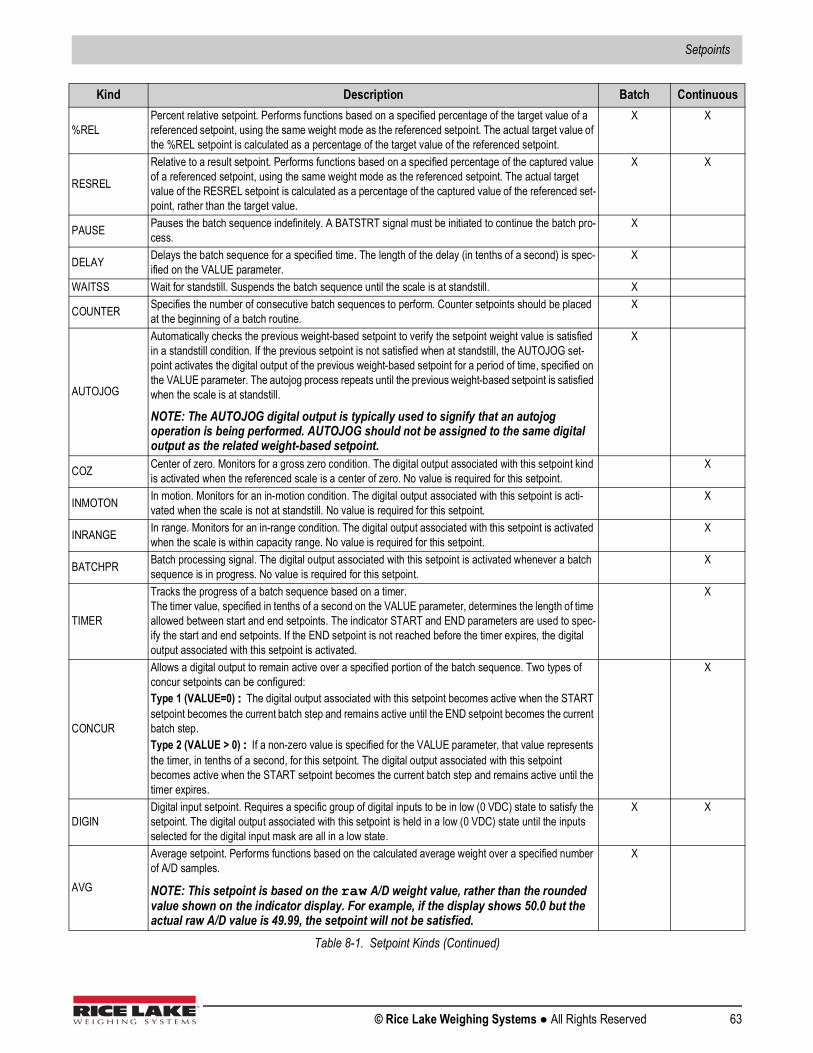
Setpoints
© Rice Lake Weighing Systems ● All Rights Reserved 63
%RELPercent relative setpoint. Performs functions based on a specified percentage of the target value of a referenced setpoint, using the same weight mode as the referenced setpoint. The actual target value of the %REL setpoint is calculated as a percentage of the target value of the referenced setpoint.
X X
RESREL
Relative to a result setpoint. Performs functions based on a specified percentage of the captured value of a referenced setpoint, using the same weight mode as the referenced setpoint. The actual target value of the RESREL setpoint is calculated as a percentage of the captured value of the referenced set-point, rather than the target value.
X X
PAUSE Pauses the batch sequence indefinitely. A BATSTRT signal must be initiated to continue the batch pro-cess.
X
DELAY Delays the batch sequence for a specified time. The length of the delay (in tenths of a second) is spec-ified on the VALUE parameter.
X
WAITSS Wait for standstill. Suspends the batch sequence until the scale is at standstill. X
COUNTER Specifies the number of consecutive batch sequences to perform. Counter setpoints should be placed at the beginning of a batch routine.
X
AUTOJOG
Automatically checks the previous weight-based setpoint to verify the setpoint weight value is satisfied in a standstill condition. If the previous setpoint is not satisfied when at standstill, the AUTOJOG set-point activates the digital output of the previous weight-based setpoint for a period of time, specified on the VALUE parameter. The autojog process repeats until the previous weight-based setpoint is satisfied when the scale is at standstill.
NOTE: The AUTOJOG digital output is typically used to signify that an autojog operation is being performed. AUTOJOG should not be assigned to the same digital output as the related weight-based setpoint.
X
COZ Center of zero. Monitors for a gross zero condition. The digital output associated with this setpoint kind is activated when the referenced scale is a center of zero. No value is required for this setpoint.
X
INMOTON In motion. Monitors for an in-motion condition. The digital output associated with this setpoint is acti-vated when the scale is not at standstill. No value is required for this setpoint.
X
INRANGE In range. Monitors for an in-range condition. The digital output associated with this setpoint is activated when the scale is within capacity range. No value is required for this setpoint.
X
BATCHPR Batch processing signal. The digital output associated with this setpoint is activated whenever a batch sequence is in progress. No value is required for this setpoint.
X
TIMER
Tracks the progress of a batch sequence based on a timer.The timer value, specified in tenths of a second on the VALUE parameter, determines the length of time allowed between start and end setpoints. The indicator START and END parameters are used to spec-ify the start and end setpoints. If the END setpoint is not reached before the timer expires, the digital output associated with this setpoint is activated.
X
CONCUR
Allows a digital output to remain active over a specified portion of the batch sequence. Two types of concur setpoints can be configured:Type 1 (VALUE=0): The digital output associated with this setpoint becomes active when the START setpoint becomes the current batch step and remains active until the END setpoint becomes the current batch step. Type 2 (VALUE > 0): If a non-zero value is specified for the VALUE parameter, that value represents the timer, in tenths of a second, for this setpoint. The digital output associated with this setpoint becomes active when the START setpoint becomes the current batch step and remains active until the timer expires.
X
DIGINDigital input setpoint. Requires a specific group of digital inputs to be in low (0 VDC) state to satisfy the setpoint. The digital output associated with this setpoint is held in a low (0 VDC) state until the inputs selected for the digital input mask are all in a low state.
X X
AVG
Average setpoint. Performs functions based on the calculated average weight over a specified number of A/D samples.
NOTE: This setpoint is based on the raw A/D weight value, rather than the rounded value shown on the indicator display. For example, if the display shows 50.0 but the actual raw A/D value is 49.99, the setpoint will not be satisfied.
X
Kind Description Batch Continuous
Table 8-1. Setpoint Kinds (Continued)
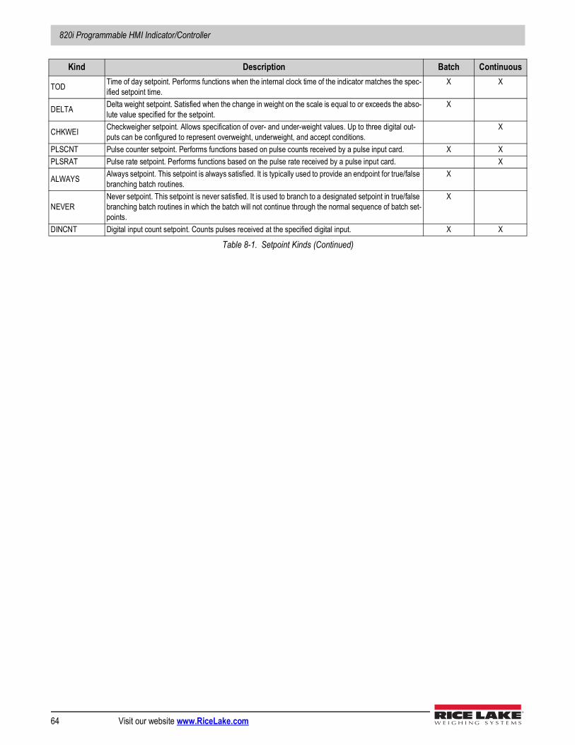
820i Programmable HMI Indicator/Controller
64 Visit our website www.RiceLake.com
TOD Time of day setpoint. Performs functions when the internal clock time of the indicator matches the spec-ified setpoint time.
X X
DELTA Delta weight setpoint. Satisfied when the change in weight on the scale is equal to or exceeds the abso-lute value specified for the setpoint.
X
CHKWEI Checkweigher setpoint. Allows specification of over- and under-weight values. Up to three digital out-puts can be configured to represent overweight, underweight, and accept conditions.
X
PLSCNT Pulse counter setpoint. Performs functions based on pulse counts received by a pulse input card. X XPLSRAT Pulse rate setpoint. Performs functions based on the pulse rate received by a pulse input card. X
ALWAYS Always setpoint. This setpoint is always satisfied. It is typically used to provide an endpoint for true/false branching batch routines.
X
NEVERNever setpoint. This setpoint is never satisfied. It is used to branch to a designated setpoint in true/false branching batch routines in which the batch will not continue through the normal sequence of batch set-points.
X
DINCNT Digital input count setpoint. Counts pulses received at the specified digital input. X X
Kind Description Batch Continuous
Table 8-1. Setpoint Kinds (Continued)

Setpoints
© Rice Lake Weighing Systems ● All Rights Reserved 65
8.2 Setpoint Menu ParametersFigure 8-1 shows the general structure of the SETPTS menu. Submenus (indicated by Go to X in Figure 8-1) for various groups of setpoint kinds are shown on the following pages (Figures 8-3 through 8-9); parameter descriptions for the submenus are provided in Table 8-2.See Table 8-1 for descriptions of each of the setpoint kinds.
Figure 8-1. SETPTS Menu
SCALES SERIAL FEATURE PFORMT SETPTS DIG I/O ALGOUT VERS
SP CFG BATCHNG
OFF
MANUAL
AUTO
SETPT 1 SETPT 100 …
–NET ACCUM
OFF
NET GROSS –GROSS ROC
RESREL PAUSE –REL +REL %REL DELAY
COZ INMOTON
COUNTER WAITSS AUTOJOG
INRANGE DIGIN AVG TIMER BATCHPR CONCUR TOD
PLSRAT CHKWEI DELTA PLSCNT
Go to A
Go to B Go to C
Go to E
Go to F
Go to D
NEVER ALWAYS
Go to G
DINCNT
Go to H
DISPLAY
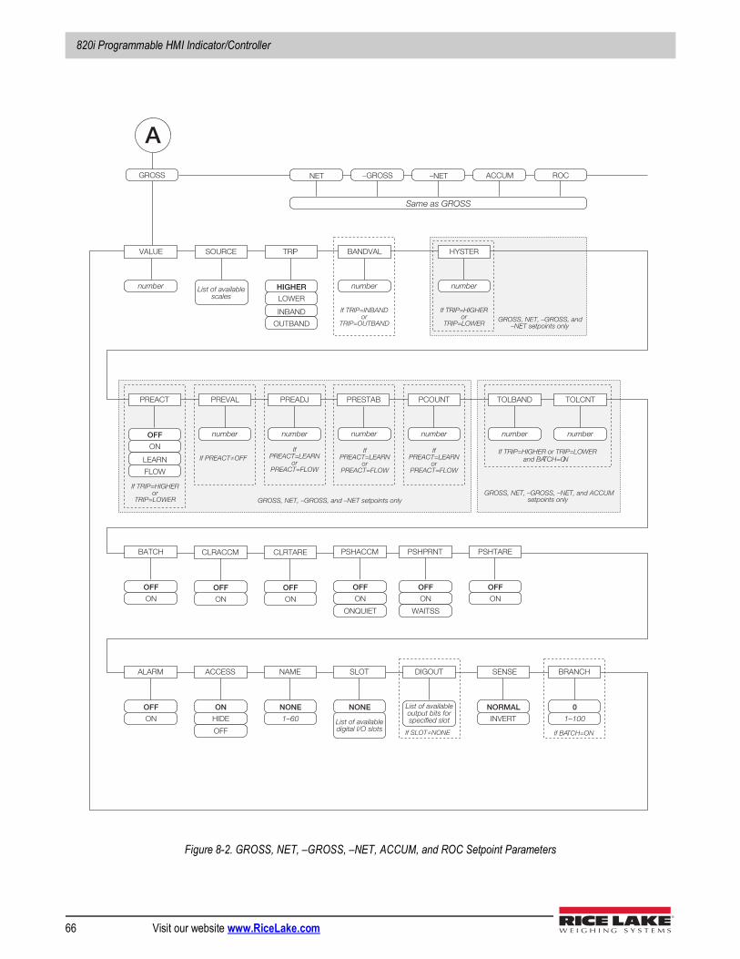
820i Programmable HMI Indicator/Controller
66 Visit our website www.RiceLake.com
Figure 8-2. GROSS, NET, –GROSS, –NET, ACCUM, and ROC Setpoint Parameters
–NET ACCUM NET GROSS –GROSS ROC
A
Same as GROSS
number
VALUE SOURCE TRI P
HIGHER
INBAND
LOWER
OUTBAND
number
BANDVAL
number
HYSTER
PREACT
OFF
LEARN
ON
FLOW
number
PREVAL
number
PREADJ
If TRIP=INBAND or
TRIP=OUTBAND
If TRIP=HIGHER or
TRIP=LOWER
If PREACT≠OFF
If TRIP=HIGHER or
TRIP=LOWER
If PREACT=LEARN
or PREACT=FLOW
PRESTAB
number
PCOUNT
If PREACT=LEARN
or PREACT=FLOW
number
TOLBAND
If TRIP=HIGHER or TRIP=LOWER and BA TCH=O N
BATCH
OFF
ON
CLRACCM
OFF
ON
CLRTARE
OFF
ON
PSHACCM
OFF
ON
PSHPRNT
OFF
ON
PSHTARE
OFF
ON
WAITSS ONQUIET
ALARM
OFF
ON
ACCESS
ON
HIDE
OFF
NAME
NONE
1–60
SLOT
NONE
List of available scales
List of available digital I/O slots
BRANCH
0
1–100
If BA TCH=ON
DIGOUT
List of available output bits for specified slot
If SLOT≠NONE
If PREACT=LEARN
or PREACT=FLOW
number number
TOLCNT
GROSS, NET, –GROSS, and –NET setpoints only
GROSS, NET, –GROSS, and –NET setpoints only GROSS, NET, –GROSS, –NET, and ACCUM
setpoints only
SENSE
NORMAL
INVERT
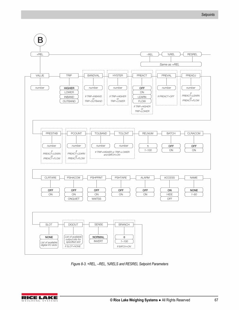
Setpoints
© Rice Lake Weighing Systems ● All Rights Reserved 67
Figure 8-3. +REL, –REL, %RELS and RESREL Setpoint Parameters
–REL %REL +REL RESREL
B
Same as +REL
number
VALUE TRIP
HIGHER
INBAND
LOWER
OUTBAND
number
BANDVAL
number
HYSTER PREACT
OFF
LEARN
ON
FLOW
number
PREVAL
number
PREADJ
If TRIP=INBAND or
TRIP=OUTBAND
If TRIP=HIGHER or
TRIP=LOWER
If PREACT≠OFF
If TRIP=HIGHER or
TRIP=LOWER
If PREACT=LEARN
or PREACT=FLOW
PRESTAB
If PREACT=LEARN
or PREACT=FLOW
number
PCOUNT
If PREACT=LEARN
or PREACT=FLOW
BATCH
OFF
ON
CLRACCM
OFF
ON
CLRTARE
OFF
ON
PSHACCM
OFF
ON
PSHPRNT
OFF
ON
PSHTARE
OFF
ON
WAITSS ONQUIET
ALARM
OFF
ON
ACCESS
ON
HIDE
OFF
NAME
NONE
1–60
BRANCH
0
1–100
If BA TCH=ON
RELNUM
1
1–100
SLOT
NONE
List of available digital I/O slots
DIGOUT
List of available output bits for specified slot
If SLOT≠NONE
number number
TOLBAND
If TRIP=HIGHER or TRIP=LOWER and BA TCH=ON
number
TOLCNT
SENSE
NORMAL
INVERT
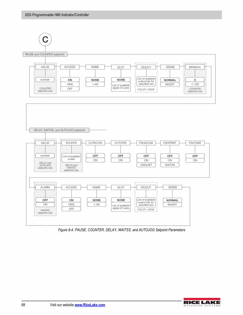
820i Programmable HMI Indicator/Controller
68 Visit our website www.RiceLake.com
Figure 8-4. PAUSE, COUNTER, DELAY, WAITSS, and AUTOJOG Setpoint Parameters
DELAY, WAITSS, and AUTOJOG setpoints
P AUSE and COUNTER setpoints
C
number
VALUE
CLRACCM
OFF
ON
CLRTARE
OFF
ON
PSHACCM
OFF
ON
PSHPRNT
OFF
ON
PSHTARE
OFF
ON
WAITSS ONQUIET
ALARM
OFF
ON
ACCESS
ON
HIDE
OFF
NAME
NONE
1–60
ACCESS
ON
HIDE
OFF
NAME
NONE
1–60
BRANCH
0
1–100
COUNTER setpoints only
COUNTER setpoints only
number
VALUE SOURCE
List of available scales
DELAY and AUTOJOG
setpoints only
WAITSS setpoints only
DELAY and WAITSS
setpoints only
SLOT
NONE
List of available digital I/O slots
DIGOUT
List of available output bits for specified slot
If SLOT≠ NONE
SLOT
NONE
List of available digital I/O slots
DIGOUT
List of available output bits for specified slot
If SLOT≠ NONE
SENSE
NORMAL
INVERT
SENSE
NORMAL
INVERT
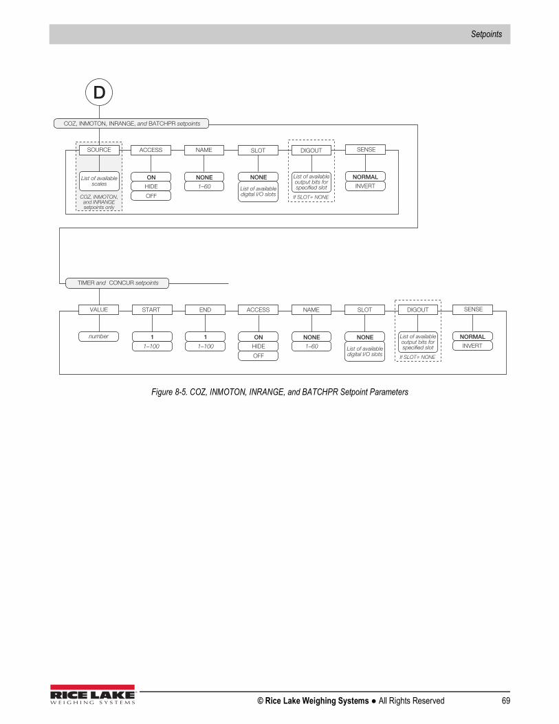
Setpoints
© Rice Lake Weighing Systems ● All Rights Reserved 69
Figure 8-5. COZ, INMOTON, INRANGE, and BATCHPR Setpoint Parameters
TIMER and CONCUR setpoints
COZ, INMOTON, INRANGE, and BATCHPR setpoints
D
ACCESS
ON
HIDE
OFF
NAME
NONE
1–60
ACCESS
ON
HIDE
OFF
NAME
NONE
1–60
number
VALUE
SOURCE
List of availablescales
COZ, INMOTON,and INRANGEsetpoints only
START
1–100
END
1–100
SLOT
NONE
List of availabledigital I/O slots
DIGOUT
List of availableoutput bits forspecified slot
If SLOT≠ NONE
SLOT
NONE
List of availabledigital I/O slots
DIGOUT
List of availableoutput bits forspecified slot
If SLOT≠ NONE
SENSE
NORMAL
INVERT
SENSE
NORMAL
INVERT
1 1
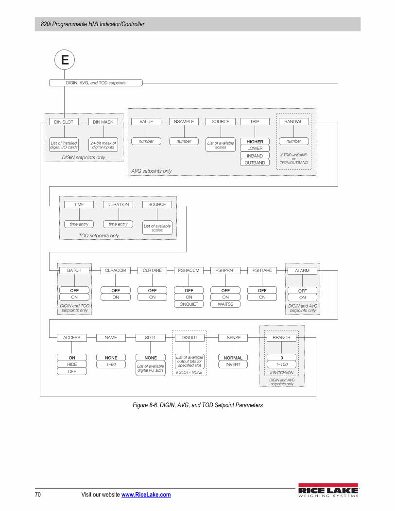
820i Programmable HMI Indicator/Controller
70 Visit our website www.RiceLake.com
Figure 8-6. DIGIN, AVG, and TOD Setpoint Parameters
DIGIN, AVG, and TOD setpoints
E
number
VALUE TRIP
HIGHER
INBAND
LOWER
OUTBAND
number
BANDV AL
If TRIP=INBAND or
TRIP=OUTBAND
ALARM
OFF
ON
ACCESS
ON
HIDE
OFF
NAME
NONE
1–60
SOURCE
List of available scales
DIN SLOT
List of installed digital I/O cards
DIN MASK
24-bit mask of digital inputs
BATCH
OFF
ON
CLRACCM
OFF
ON
CLRTARE
OFF
ON
PSHACCM
OFF
ON
PSHPRNT
OFF
ON
PSHTARE
OFF
ON
WAITSS ONQUIET
BRANCH
0
1–100
If BATCH=ON
number
NSAMPLE
DIGIN and AVG setpoints only
DIGIN setpoints only
AVG setpoints only
SOURCE
List of available scales
time entr y
TIME
time entr y
DURATION
TOD setpoints only
SLOT
NONE
List of available digital I/O slots
DIGOUT
List of available output bits for specified slot
If SLOT≠ NONE
DIGIN and TOD setpoints only
DIGIN and AVG setpoints only
SENSE
NORMAL
INVERT
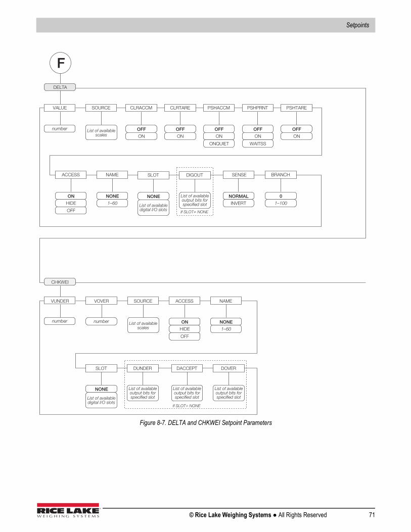
Setpoints
© Rice Lake Weighing Systems ● All Rights Reserved 71
Figure 8-7. DELTA and CHKWEI Setpoint Parameters
DELTA
F
number
VALUE
ACCESS
ON
HIDE
OFF
NAME
NONE
1–60
CLRACCM
OFF
ON
CLRTARE
OFF
ON
PSHACCM
OFF
ON
PSHPRNT
OFF
ON
PSHTARE
OFF
ON
WAITSS ONQUIET
BRANCH
0
1–100
SOURCE
List of available scales
CHKWEI
number
SOURCE
List of available scales
number
ACCESS
ON
HIDE
OFF
NAME
NONE
1–60
VOVER VUNDER
SLOT
NONE
List of available digital I/O slots
DIGOUT
List of available output bits for specified slot
If SLOT≠ NONE
SLOT
NONE
List of available digital I/O slots
DUNDER
List of available output bits for specified slot
If SLOT≠ NONE
DACCEPT
List of available output bits for specified slot
DOVER
List of available output bits for specified slot
SENSE
NORMAL
INVERT
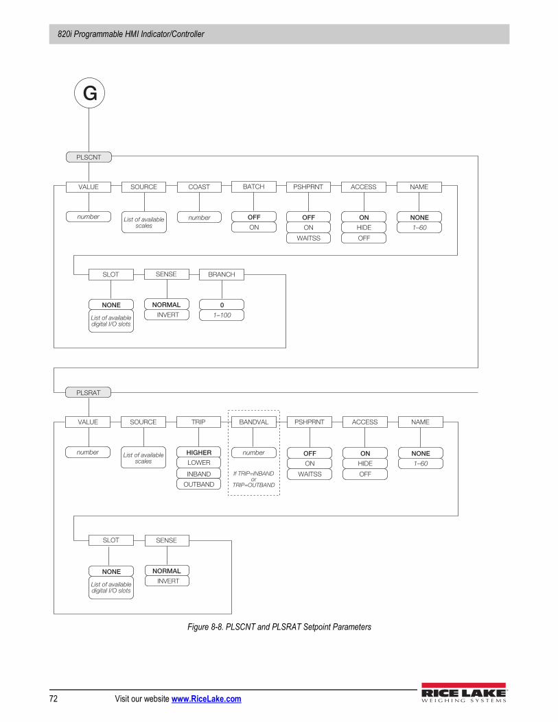
820i Programmable HMI Indicator/Controller
72 Visit our website www.RiceLake.com
Figure 8-8. PLSCNT and PLSRAT Setpoint Parameters
number
VALUE COAST
number
PSHPRNT
OFF
ON
WAITSS
SOURCE
List of available scales
PLSCNT
ACCESS
ON
HIDE
OFF
NAME
NONE
1–60
BRANCH
0
1–100
SLOT
NONE
List of available digital I/O slots
G
number
VALUE PSHPRNT
OFF
ON
WAITSS
SOURCE
List of available scales
PLSRAT
ACCESS
ON
HIDE
OFF
NAME
NONE
1–60
SLOT
NONE
List of available digital I/O slots
TRIP
HIGHER
INBAND
LOWER
OUTBAND
number
BANDVAL
If TRIP=INBAND or
TRIP=OUTBAND
BATCH
OFF
ON
SENSE
NORMAL
INVERT
SENSE
NORMAL
INVERT
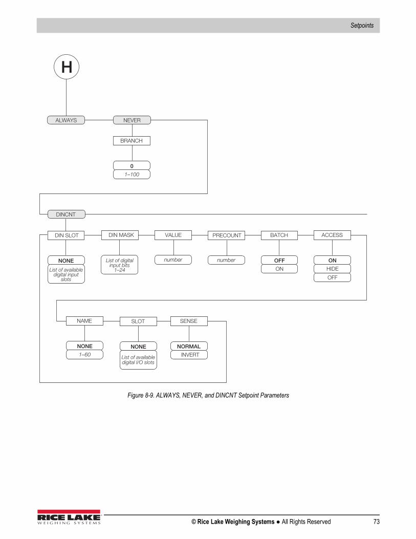
Setpoints
© Rice Lake Weighing Systems ● All Rights Reserved 73
Figure 8-9. ALWAYS, NEVER, and DINCNT Setpoint Parameters
ALWAYS NEVER
BRANCH
0
1–100
H
DINCNT
DIN SLOT
NONE
List of available digital input
slots
DIN MASK
List of digital input bits
1–24
number
VALUE
number
PRECOUNT BATCH
OFF
ON
ACCESS
ON
HIDE
OFF
NAME
NONE
1–60
SLOT
NONE
List of available digital I/O slots
SENSE
NORMAL
INVERT
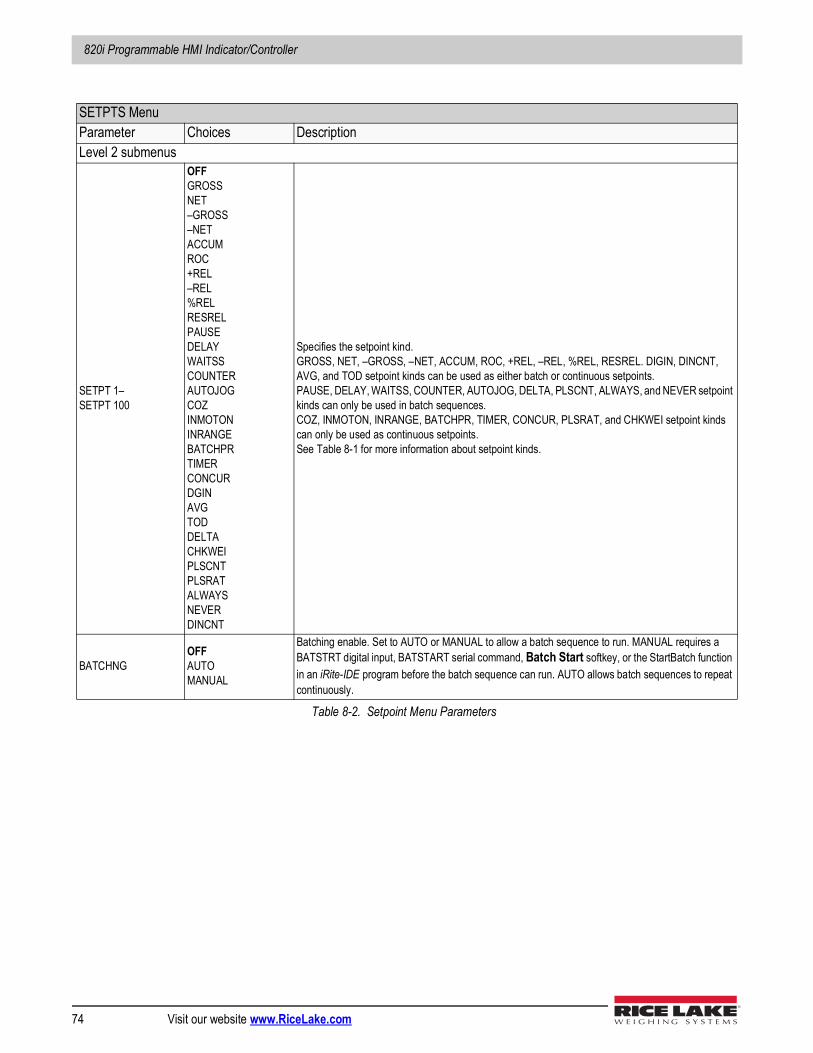
820i Programmable HMI Indicator/Controller
74 Visit our website www.RiceLake.com
SETPTS MenuParameter Choices DescriptionLevel 2 submenus
SETPT 1–SETPT 100
OFFGROSSNET–GROSS–NETACCUMROC+REL–REL%RELRESRELPAUSEDELAYWAITSSCOUNTERAUTOJOGCOZINMOTONINRANGEBATCHPRTIMERCONCURDGINAVGTODDELTACHKWEIPLSCNTPLSRATALWAYSNEVERDINCNT
Specifies the setpoint kind. GROSS, NET, –GROSS, –NET, ACCUM, ROC, +REL, –REL, %REL, RESREL. DIGIN, DINCNT, AVG, and TOD setpoint kinds can be used as either batch or continuous setpoints.PAUSE, DELAY, WAITSS, COUNTER, AUTOJOG, DELTA, PLSCNT, ALWAYS, and NEVER setpoint kinds can only be used in batch sequences.COZ, INMOTON, INRANGE, BATCHPR, TIMER, CONCUR, PLSRAT, and CHKWEI setpoint kinds can only be used as continuous setpoints.See Table 8-1 for more information about setpoint kinds.
BATCHNGOFFAUTOMANUAL
Batching enable. Set to AUTO or MANUAL to allow a batch sequence to run. MANUAL requires a BATSTRT digital input, BATSTART serial command, Batch Start softkey, or the StartBatch function in an iRite-IDE program before the batch sequence can run. AUTO allows batch sequences to repeat continuously.
Table 8-2. Setpoint Menu Parameters
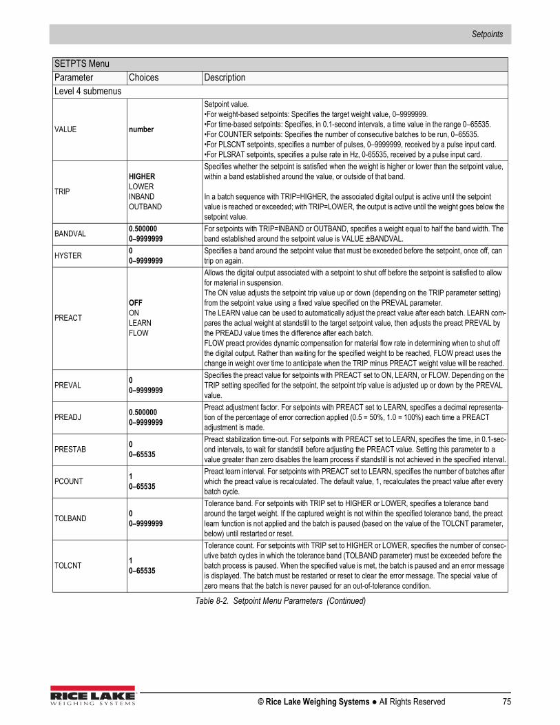
Setpoints
© Rice Lake Weighing Systems ● All Rights Reserved 75
Level 4 submenus
VALUE number
Setpoint value. •For weight-based setpoints: Specifies the target weight value, 0–9999999.•For time-based setpoints: Specifies, in 0.1-second intervals, a time value in the range 0–65535.•For COUNTER setpoints: Specifies the number of consecutive batches to be run, 0–65535.•For PLSCNT setpoints, specifies a number of pulses, 0–9999999, received by a pulse input card.•For PLSRAT setpoints, specifies a pulse rate in Hz, 0-65535, received by a pulse input card.
TRIP
HIGHERLOWERINBANDOUTBAND
Specifies whether the setpoint is satisfied when the weight is higher or lower than the setpoint value, within a band established around the value, or outside of that band.
In a batch sequence with TRIP=HIGHER, the associated digital output is active until the setpoint value is reached or exceeded; with TRIP=LOWER, the output is active until the weight goes below the setpoint value.
BANDVAL 0.5000000–9999999
For setpoints with TRIP=INBAND or OUTBAND, specifies a weight equal to half the band width. The band established around the setpoint value is VALUE ±BANDVAL.
HYSTER 00–9999999
Specifies a band around the setpoint value that must be exceeded before the setpoint, once off, can trip on again.
PREACT
OFFONLEARNFLOW
Allows the digital output associated with a setpoint to shut off before the setpoint is satisfied to allow for material in suspension.The ON value adjusts the setpoint trip value up or down (depending on the TRIP parameter setting) from the setpoint value using a fixed value specified on the PREVAL parameter.The LEARN value can be used to automatically adjust the preact value after each batch. LEARN com-pares the actual weight at standstill to the target setpoint value, then adjusts the preact PREVAL by the PREADJ value times the difference after each batch.FLOW preact provides dynamic compensation for material flow rate in determining when to shut off the digital output. Rather than waiting for the specified weight to be reached, FLOW preact uses the change in weight over time to anticipate when the TRIP minus PREACT weight value will be reached.
PREVAL 00–9999999
Specifies the preact value for setpoints with PREACT set to ON, LEARN, or FLOW. Depending on the TRIP setting specified for the setpoint, the setpoint trip value is adjusted up or down by the PREVAL value.
PREADJ 0.5000000–9999999
Preact adjustment factor. For setpoints with PREACT set to LEARN, specifies a decimal representa-tion of the percentage of error correction applied (0.5 = 50%, 1.0 = 100%) each time a PREACT adjustment is made.
PRESTAB 00–65535
Preact stabilization time-out. For setpoints with PREACT set to LEARN, specifies the time, in 0.1-sec-ond intervals, to wait for standstill before adjusting the PREACT value. Setting this parameter to a value greater than zero disables the learn process if standstill is not achieved in the specified interval.
PCOUNT 10–65535
Preact learn interval. For setpoints with PREACT set to LEARN, specifies the number of batches after which the preact value is recalculated. The default value, 1, recalculates the preact value after every batch cycle.
TOLBAND 00–9999999
Tolerance band. For setpoints with TRIP set to HIGHER or LOWER, specifies a tolerance band around the target weight. If the captured weight is not within the specified tolerance band, the preact learn function is not applied and the batch is paused (based on the value of the TOLCNT parameter, below) until restarted or reset.
TOLCNT 10–65535
Tolerance count. For setpoints with TRIP set to HIGHER or LOWER, specifies the number of consec-utive batch cycles in which the tolerance band (TOLBAND parameter) must be exceeded before the batch process is paused. When the specified value is met, the batch is paused and an error message is displayed. The batch must be restarted or reset to clear the error message. The special value of zero means that the batch is never paused for an out-of-tolerance condition.
SETPTS MenuParameter Choices Description
Table 8-2. Setpoint Menu Parameters (Continued)
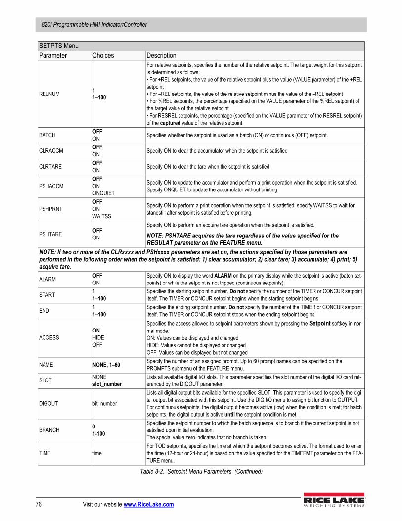
820i Programmable HMI Indicator/Controller
76 Visit our website www.RiceLake.com
RELNUM 11–100
For relative setpoints, specifies the number of the relative setpoint. The target weight for this setpoint is determined as follows:• For +REL setpoints, the value of the relative setpoint plus the value (VALUE parameter) of the +REL setpoint• For –REL setpoints, the value of the relative setpoint minus the value of the –REL setpoint• For %REL setpoints, the percentage (specified on the VALUE parameter of the %REL setpoint) of the target value of the relative setpoint• For RESREL setpoints, the percentage (specified on the VALUE parameter of the RESREL setpoint) of the captured value of the relative setpoint
BATCH OFFON Specifies whether the setpoint is used as a batch (ON) or continuous (OFF) setpoint.
CLRACCM OFFON Specify ON to clear the accumulator when the setpoint is satisfied
CLRTARE OFFON Specify ON to clear the tare when the setpoint is satisfied
PSHACCMOFFONONQUIET
Specify ON to update the accumulator and perform a print operation when the setpoint is satisfied. Specify ONQUIET to update the accumulator without printing.
PSHPRNTOFFONWAITSS
Specify ON to perform a print operation when the setpoint is satisfied; specify WAITSS to wait for standstill after setpoint is satisfied before printing.
PSHTARE OFFON
Specify ON to perform an acquire tare operation when the setpoint is satisfied.
NOTE: PSHTARE acquires the tare regardless of the value specified for the REGULAT parameter on the FEATURE menu.
NOTE: If two or more of the CLRxxxx and PSHxxxx parameters are set on, the actions specified by those parameters are performed in the following order when the setpoint is satisfied: 1) clear accumulator; 2) clear tare; 3) accumulate; 4) print; 5) acquire tare.
ALARM OFFON
Specify ON to display the word ALARM on the primary display while the setpoint is active (batch set-points) or while the setpoint is not tripped (continuous setpoints).
START 11–100
Specifies the starting setpoint number. Do not specify the number of the TIMER or CONCUR setpoint itself. The TIMER or CONCUR setpoint begins when the starting setpoint begins.
END 11–100
Specifies the ending setpoint number. Do not specify the number of the TIMER or CONCUR setpoint itself. The TIMER or CONCUR setpoint stops when the ending setpoint begins.
ACCESSONHIDEOFF
Specifies the access allowed to setpoint parameters shown by pressing the Setpoint softkey in nor-mal mode. ON: Values can be displayed and changedHIDE: Values cannot be displayed or changedOFF: Values can be displayed but not changed
NAME NONE, 1–60 Specify the number of an assigned prompt. Up to 60 prompt names can be specified on the PROMPTS submenu of the FEATURE menu.
SLOT NONEslot_number
Lists all available digital I/O slots. This parameter specifies the slot number of the digital I/O card ref-erenced by the DIGOUT parameter.
DIGOUT bit_number
Lists all digital output bits available for the specified SLOT. This parameter is used to specify the digi-tal output bit associated with this setpoint. Use the DIG I/O menu to assign bit function to OUTPUT.For continuous setpoints, the digital output becomes active (low) when the condition is met; for batch setpoints, the digital output is active until the setpoint condition is met.
BRANCH 01-100
Specifies the setpoint number to which the batch sequence is to branch if the current setpoint is not satisfied upon initial evaluation.The special value zero indicates that no branch is taken.
TIME timeFor TOD setpoints, specifies the time at which the setpoint becomes active. The format used to enter the time (12-hour or 24-hour) is based on the value specified for the TIMEFMT parameter on the FEA-TURE menu.
SETPTS MenuParameter Choices Description
Table 8-2. Setpoint Menu Parameters (Continued)
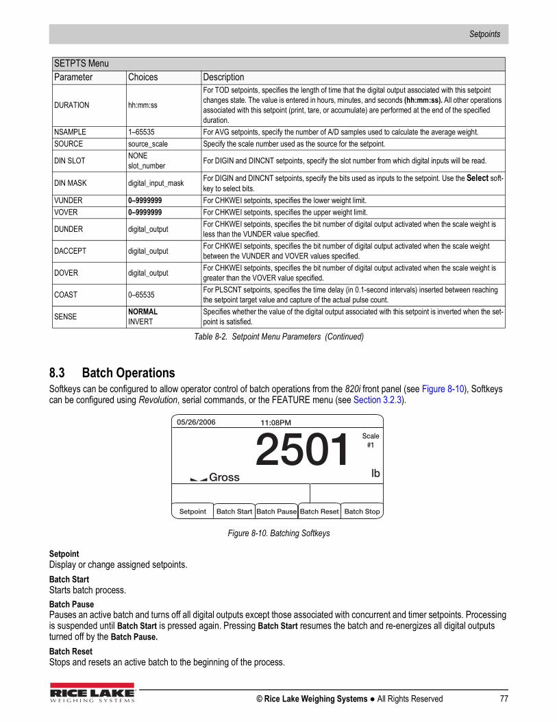
Setpoints
© Rice Lake Weighing Systems ● All Rights Reserved 77
8.3 Batch OperationsSoftkeys can be configured to allow operator control of batch operations from the 820i front panel (see Figure 8-10), Softkeys can be configured using Revolution, serial commands, or the FEATURE menu (see Section 3.2.3).
Figure 8-10. Batching Softkeys
SetpointDisplay or change assigned setpoints.Batch StartStarts batch process.Batch PausePauses an active batch and turns off all digital outputs except those associated with concurrent and timer setpoints. Processing is suspended until Batch Start is pressed again. Pressing Batch Start resumes the batch and re-energizes all digital outputs turned off by the Batch Pause.Batch ResetStops and resets an active batch to the beginning of the process.
DURATION hh:mm:ss
For TOD setpoints, specifies the length of time that the digital output associated with this setpoint changes state. The value is entered in hours, minutes, and seconds (hh:mm:ss). All other operations associated with this setpoint (print, tare, or accumulate) are performed at the end of the specified duration.
NSAMPLE 1–65535 For AVG setpoints, specify the number of A/D samples used to calculate the average weight.SOURCE source_scale Specify the scale number used as the source for the setpoint.
DIN SLOT NONEslot_number For DIGIN and DINCNT setpoints, specify the slot number from which digital inputs will be read.
DIN MASK digital_input_mask For DIGIN and DINCNT setpoints, specify the bits used as inputs to the setpoint. Use the Select soft-key to select bits.
VUNDER 0–9999999 For CHKWEI setpoints, specifies the lower weight limit.VOVER 0–9999999 For CHKWEI setpoints, specifies the upper weight limit.
DUNDER digital_output For CHKWEI setpoints, specifies the bit number of digital output activated when the scale weight is less than the VUNDER value specified.
DACCEPT digital_output For CHKWEI setpoints, specifies the bit number of digital output activated when the scale weight between the VUNDER and VOVER values specified.
DOVER digital_output For CHKWEI setpoints, specifies the bit number of digital output activated when the scale weight is greater than the VOVER value specified.
COAST 0–65535 For PLSCNT setpoints, specifies the time delay (in 0.1-second intervals) inserted between reaching the setpoint target value and capture of the actual pulse count.
SENSE NORMALINVERT
Specifies whether the value of the digital output associated with this setpoint is inverted when the set-point is satisfied.
SETPTS MenuParameter Choices Description
Table 8-2. Setpoint Menu Parameters (Continued)
05/26/2006 11:08PM
2501 Scale #1
lb Gross
Setpoint Batch Start Batch Pause Batch Reset Batch Stop
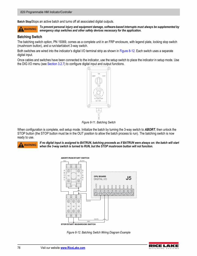
820i Programmable HMI Indicator/Controller
78 Visit our website www.RiceLake.com
Batch StopStops an active batch and turns off all associated digital outputs.To prevent personal injury and equipment damage, software-based interrupts must always be supplemented by emergency stop switches and other safety devices necessary for the application.
Batching SwitchThe batching switch option, PN 19369, comes as a complete unit in an FRP enclosure, with legend plate, locking stop switch (mushroom button), and a run/start/abort 3-way switch.Both switches are wired into the indicator’s digital I/O terminal strip as shown in Figure 8-12. Each switch uses a separate digital input.Once cables and switches have been connected to the indicator, use the setup switch to place the indicator in setup mode. Use the DIG I/O menu (see Section 3.2.7) to configure digital input and output functions.
Figure 8-11. Batching Switch
When configuration is complete, exit setup mode. Initialize the batch by turning the 3-way switch to ABORT, then unlock the STOP button (the STOP button must be in the OUT position to allow the batch process to run). The batching switch is now ready to use.
If no digital input is assigned to BATRUN, batching proceeds as if BATRUN were always on: the batch will start when the 3-way switch is turned to RUN, but the STOP mushroom button will not function.
Figure 8-12. Batching Switch Wiring Diagram Example
WARNING
WARNING
RED
WHITE
BLACK
RED BLACK
STOP/START MUSHROOM SWITCH
ABORT/RUN/START SWITCH
A
B
O
R
T
S
T
A
R
T
NO NC NC
NO NO
J5
+5V
DC
GN
D
DIO
1
DIO
2
DIO
3
DIO
4
DIGITAL I/O CPU BOARD
1 2 3 4 5 6 7 8 9 10
DIO
5
DIO
6
DIO
7
DIO
8
1
2
1
2
3
4
3
4
3
4
Setpoints
© Rice Lake Weighing Systems ● All Rights Reserved 79
To begin a batch process, turn the 3-way switch to START momentarily. If the STOP button is pushed during the batch process, the process halts and the button locks in the IN position. The START switch is ignored while the STOP button is locked in the IN position. The STOP button must be turned counterclockwise to unlock it, then released into the OUT position to enable the 3-way switch. To restart an interrupted batch from the step where it left off, do the following:
1. Unlock STOP button (OUT position)2. Turn 3-way switch to START
To restart an interrupted batch from the first batch step, do the following:1. Turn 3-way switch to ABORT2. Unlock STOP button (OUT position)3. Turn 3-way switch to START
Use this procedure (or the BATRESET serial command) to initialize the new batch routine following any change to the setpoint configuration.Note
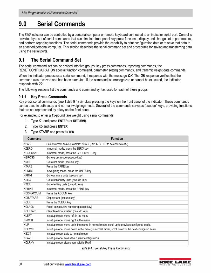
820i Programmable HMI Indicator/Controller
80 Visit our website www.RiceLake.com
9.0 Serial CommandsThe 820i indicator can be controlled by a personal computer or remote keyboard connected to an indicator serial port. Control is provided by a set of serial commands that can simulate front panel key press functions, display and change setup parameters, and perform reporting functions. The serial commands provide the capability to print configuration data or to save that data to an attached personal computer. This section describes the serial command set and procedures for saving and transferring data using the serial ports.
9.1 The Serial Command SetThe serial command set can be divided into five groups: key press commands, reporting commands, the RESETCONFIGURATION special function command, parameter setting commands, and transmit weight data commands. When the indicator processes a serial command, it responds with the message OK. The OK response verifies that the command was received and has been executed. If the command is unrecognized or cannot be executed, the indicator responds with ??.The following sections list the commands and command syntax used for each of these groups.
9.1.1 Key Press CommandsKey press serial commands (see Table 9-1) simulate pressing the keys on the front panel of the indicator. These commands can be used in both setup and normal (weighing) mode. Several of the commands serve as “pseudo” keys, providing functions that are not represented by a key on the front panel.For example, to enter a 15-pound tare weight using serial commands:
1. Type K1 and press ENTER (or RETURN).2. Type K5 and press ENTER.3. Type KTARE and press ENTER.
Command FunctionKBASE Select current scale (Example: KBASE, K2, KENTER to select Scale #2)KZERO In normal mode, press the ZERO keyKGROSSNET In normal mode, press the GROSS/NET keyKGROSS Go to gross mode (pseudo key)KNET Go to net mode (pseudo key)KTARE Press the TARE keyKUNITS In weighing mode, press the UNITS keyKPRIM Go to primary units (pseudo key)KSEC Go to secondary units (pseudo key)KTER Go to tertiary units (pseudo key)KPRINT In normal mode, press the PRINT keyKDISPACCUM Press the ACCUM keyKDISPTARE Display tare (pseudo key)KCLR Press the CLEAR keyKCLRCN Reset consecutive number (pseudo key)KCLRTAR Clear tare from system (pseudo key)KLEFT In setup mode, move left in the menuKRIGHT In setup mode, move right in the menuKUP In setup mode, move up in the menu; in normal mode, scroll up to previous configured scale.KDOWN In setup mode, move down in the menu; in normal mode, scroll down to the next configured scale.KEXIT In setup mode, exits to normal modeKSAVE In setup mode, saves the current configurationKCLRNV In setup mode, clears non-volatile RAM
Table 9-1. Serial Key Press Commands
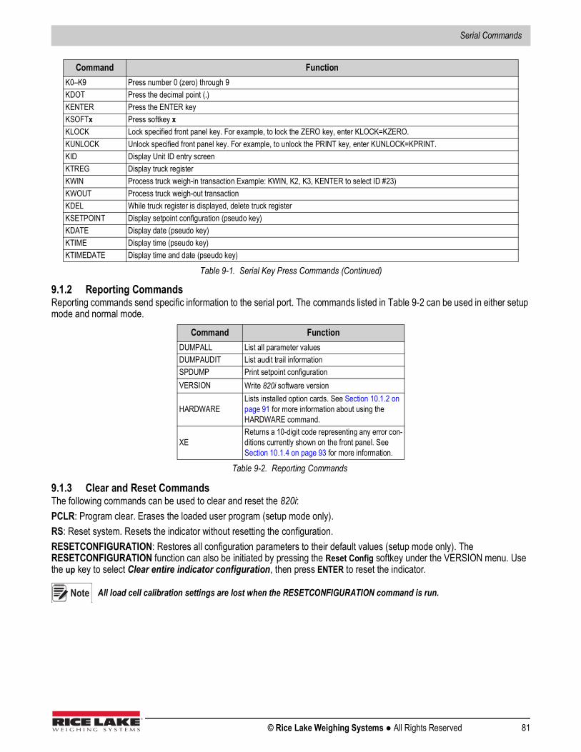
Serial Commands
© Rice Lake Weighing Systems ● All Rights Reserved 81
9.1.2 Reporting CommandsReporting commands send specific information to the serial port. The commands listed in Table 9-2 can be used in either setup mode and normal mode.
9.1.3 Clear and Reset CommandsThe following commands can be used to clear and reset the 820i:PCLR: Program clear. Erases the loaded user program (setup mode only).RS: Reset system. Resets the indicator without resetting the configuration.RESETCONFIGURATION: Restores all configuration parameters to their default values (setup mode only). The RESETCONFIGURATION function can also be initiated by pressing the Reset Config softkey under the VERSION menu. Use the up key to select Clear entire indicator configuration, then press ENTER to reset the indicator.
All load cell calibration settings are lost when the RESETCONFIGURATION command is run.
K0–K9 Press number 0 (zero) through 9KDOT Press the decimal point (.)KENTER Press the ENTER keyKSOFTx Press softkey xKLOCK Lock specified front panel key. For example, to lock the ZERO key, enter KLOCK=KZERO.KUNLOCK Unlock specified front panel key. For example, to unlock the PRINT key, enter KUNLOCK=KPRINT.KID Display Unit ID entry screenKTREG Display truck registerKWIN Process truck weigh-in transaction Example: KWIN, K2, K3, KENTER to select ID #23)KWOUT Process truck weigh-out transactionKDEL While truck register is displayed, delete truck registerKSETPOINT Display setpoint configuration (pseudo key)KDATE Display date (pseudo key)KTIME Display time (pseudo key)KTIMEDATE Display time and date (pseudo key)
Command FunctionDUMPALL List all parameter valuesDUMPAUDIT List audit trail informationSPDUMP Print setpoint configurationVERSION Write 820i software version
HARDWARELists installed option cards. See Section 10.1.2 on page 91 for more information about using the HARDWARE command.
XEReturns a 10-digit code representing any error con-ditions currently shown on the front panel. See Section 10.1.4 on page 93 for more information.
Table 9-2. Reporting Commands
Command Function
Table 9-1. Serial Key Press Commands (Continued)
Note
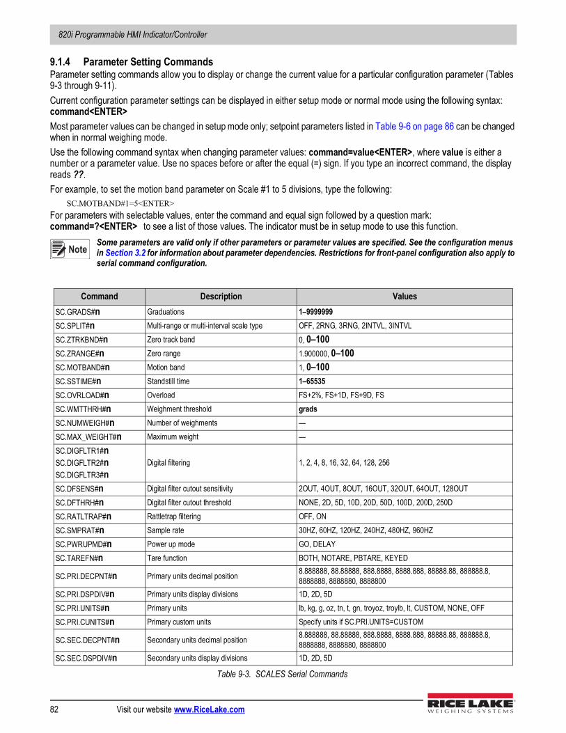
820i Programmable HMI Indicator/Controller
82 Visit our website www.RiceLake.com
9.1.4 Parameter Setting CommandsParameter setting commands allow you to display or change the current value for a particular configuration parameter (Tables 9-3 through 9-11).Current configuration parameter settings can be displayed in either setup mode or normal mode using the following syntax: command<ENTER>Most parameter values can be changed in setup mode only; setpoint parameters listed in Table 9-6 on page 86 can be changed when in normal weighing mode. Use the following command syntax when changing parameter values: command=value<ENTER>, where value is either a number or a parameter value. Use no spaces before or after the equal (=) sign. If you type an incorrect command, the display reads ??. For example, to set the motion band parameter on Scale #1 to 5 divisions, type the following:
SC.MOTBAND#1=5<ENTER>For parameters with selectable values, enter the command and equal sign followed by a question mark: command=?<ENTER> to see a list of those values. The indicator must be in setup mode to use this function.
Some parameters are valid only if other parameters or parameter values are specified. See the configuration menus in Section 3.2 for information about parameter dependencies. Restrictions for front-panel configuration also apply to serial command configuration.
Command Description ValuesSC.GRADS#n Graduations 1–9999999SC.SPLIT#n Multi-range or multi-interval scale type OFF, 2RNG, 3RNG, 2INTVL, 3INTVLSC.ZTRKBND#n Zero track band 0, 0–100SC.ZRANGE#n Zero range 1.900000, 0–100SC.MOTBAND#n Motion band 1, 0–100SC.SSTIME#n Standstill time 1–65535SC.OVRLOAD#n Overload FS+2%, FS+1D, FS+9D, FSSC.WMTTHRH#n Weighment threshold gradsSC.NUMWEIGH#n Number of weighments —SC.MAX_WEIGHT#n Maximum weight —SC.DIGFLTR1#nSC.DIGFLTR2#nSC.DIGFLTR3#n
Digital filtering 1, 2, 4, 8, 16, 32, 64, 128, 256
SC.DFSENS#n Digital filter cutout sensitivity 2OUT, 4OUT, 8OUT, 16OUT, 32OUT, 64OUT, 128OUTSC.DFTHRH#n Digital filter cutout threshold NONE, 2D, 5D, 10D, 20D, 50D, 100D, 200D, 250DSC.RATLTRAP#n Rattletrap filtering OFF, ONSC.SMPRAT#n Sample rate 30HZ, 60HZ, 120HZ, 240HZ, 480HZ, 960HZSC.PWRUPMD#n Power up mode GO, DELAYSC.TAREFN#n Tare function BOTH, NOTARE, PBTARE, KEYED
SC.PRI.DECPNT#n Primary units decimal position 8.888888, 88.88888, 888.8888, 8888.888, 88888.88, 888888.8, 8888888, 8888880, 8888800
SC.PRI.DSPDIV#n Primary units display divisions 1D, 2D, 5DSC.PRI.UNITS#n Primary units lb, kg, g, oz, tn, t, gn, troyoz, troylb, lt, CUSTOM, NONE, OFFSC.PRI.CUNITS#n Primary custom units Specify units if SC.PRI.UNITS=CUSTOM
SC.SEC.DECPNT#n Secondary units decimal position 8.888888, 88.88888, 888.8888, 8888.888, 88888.88, 888888.8, 8888888, 8888880, 8888800
SC.SEC.DSPDIV#n Secondary units display divisions 1D, 2D, 5D
Table 9-3. SCALES Serial Commands
Note
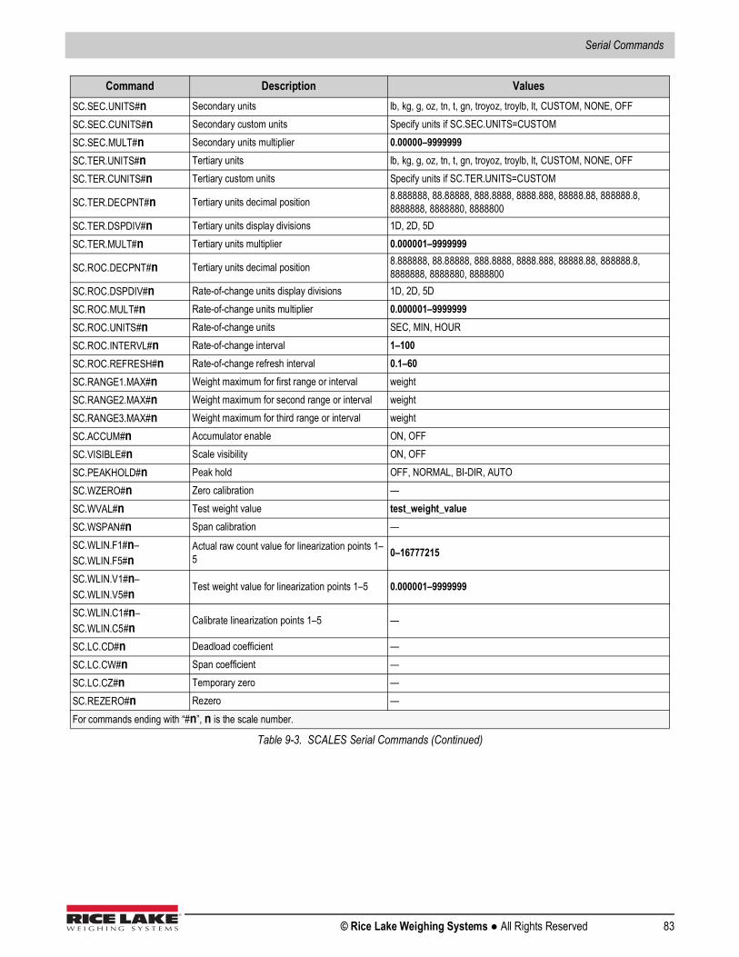
Serial Commands
© Rice Lake Weighing Systems ● All Rights Reserved 83
SC.SEC.UNITS#n Secondary units lb, kg, g, oz, tn, t, gn, troyoz, troylb, lt, CUSTOM, NONE, OFFSC.SEC.CUNITS#n Secondary custom units Specify units if SC.SEC.UNITS=CUSTOMSC.SEC.MULT#n Secondary units multiplier 0.00000–9999999SC.TER.UNITS#n Tertiary units lb, kg, g, oz, tn, t, gn, troyoz, troylb, lt, CUSTOM, NONE, OFFSC.TER.CUNITS#n Tertiary custom units Specify units if SC.TER.UNITS=CUSTOM
SC.TER.DECPNT#n Tertiary units decimal position 8.888888, 88.88888, 888.8888, 8888.888, 88888.88, 888888.8, 8888888, 8888880, 8888800
SC.TER.DSPDIV#n Tertiary units display divisions 1D, 2D, 5DSC.TER.MULT#n Tertiary units multiplier 0.000001–9999999
SC.ROC.DECPNT#n Tertiary units decimal position 8.888888, 88.88888, 888.8888, 8888.888, 88888.88, 888888.8, 8888888, 8888880, 8888800
SC.ROC.DSPDIV#n Rate-of-change units display divisions 1D, 2D, 5DSC.ROC.MULT#n Rate-of-change units multiplier 0.000001–9999999SC.ROC.UNITS#n Rate-of-change units SEC, MIN, HOURSC.ROC.INTERVL#n Rate-of-change interval 1–100SC.ROC.REFRESH#n Rate-of-change refresh interval 0.1–60SC.RANGE1.MAX#n Weight maximum for first range or interval weightSC.RANGE2.MAX#n Weight maximum for second range or interval weightSC.RANGE3.MAX#n Weight maximum for third range or interval weightSC.ACCUM#n Accumulator enable ON, OFFSC.VISIBLE#n Scale visibility ON, OFFSC.PEAKHOLD#n Peak hold OFF, NORMAL, BI-DIR, AUTOSC.WZERO#n Zero calibration —SC.WVAL#n Test weight value test_weight_valueSC.WSPAN#n Span calibration —SC.WLIN.F1#n–SC.WLIN.F5#n
Actual raw count value for linearization points 1–5 0–16777215
SC.WLIN.V1#n–SC.WLIN.V5#n Test weight value for linearization points 1–5 0.000001–9999999
SC.WLIN.C1#n–SC.WLIN.C5#n Calibrate linearization points 1–5 —
SC.LC.CD#n Deadload coefficient —SC.LC.CW#n Span coefficient —SC.LC.CZ#n Temporary zero —SC.REZERO#n Rezero —For commands ending with “#n”, n is the scale number.
Command Description Values
Table 9-3. SCALES Serial Commands (Continued)
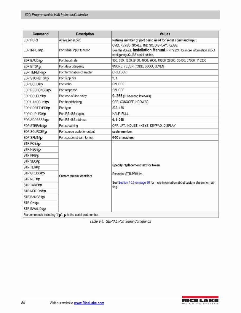
820i Programmable HMI Indicator/Controller
84 Visit our website www.RiceLake.com
Command Description ValuesEDP.PORT Active serial port Returns number of port being used for serial command input
EDP.INPUT#p Port serial input functionCMD, KEYBD, SCALE, IND SC, DISPLAY, IQUBESee the iQUBE Installation Manual, PN 77224, for more information about configuring iQUBE serial scales.
EDP.BAUD#p Port baud rate 300, 600, 1200, 2400, 4800, 9600, 19200, 28800, 38400, 57600, 115200EDP.BITS#p Port data bits/parity 8NONE, 7EVEN, 7ODD, 8ODD, 8EVENEDP.TERMIN#p Port termination character CR/LF, CREDP.STOPBITS#p Port stop bits 2, 1EDP.ECHO#p Port echo ON, OFFEDP.RESPONSE#p Port response ON, OFFEDP.EOLDLY#p Port end-of-line delay 0–255 (0.1-second intervals)EDP.HANDSHK#p Port handshaking OFF, XONXOFF, HRDWAREDP.PORTTYPE#p Port type 232, 485EDP.DUPLEX#p Port RS-485 duplex HALF, FULLEDP.ADDRESS#p Port RS-485 address 0, 1–255EDP.STREAM#p Port streaming OFF, LFT, INDUST, 4KEYS, KEYPAD, DISPLAYEDP.SOURCE#p Port source scale for output scale_numberEDP.SFMT#p Port custom stream format 0-50 charactersSTR.POS#p
Custom stream identifiers
Specify replacement text for token
Example: STR.PRI#1=L
See Section 10.5 on page 96 for more information about custom stream format-ting.
STR.NEG#pSTR.PRI#pSTR.SEC#pSTR.TER#pSTR.GROSS#pSTR.NET#pSTR.TARE#pSTR.MOTION#pSTR.RANGE#pSTR.OK#pSTR.INVALID#pFor commands including “#p”, p is the serial port number.
Table 9-4. SERIAL Port Serial Commands
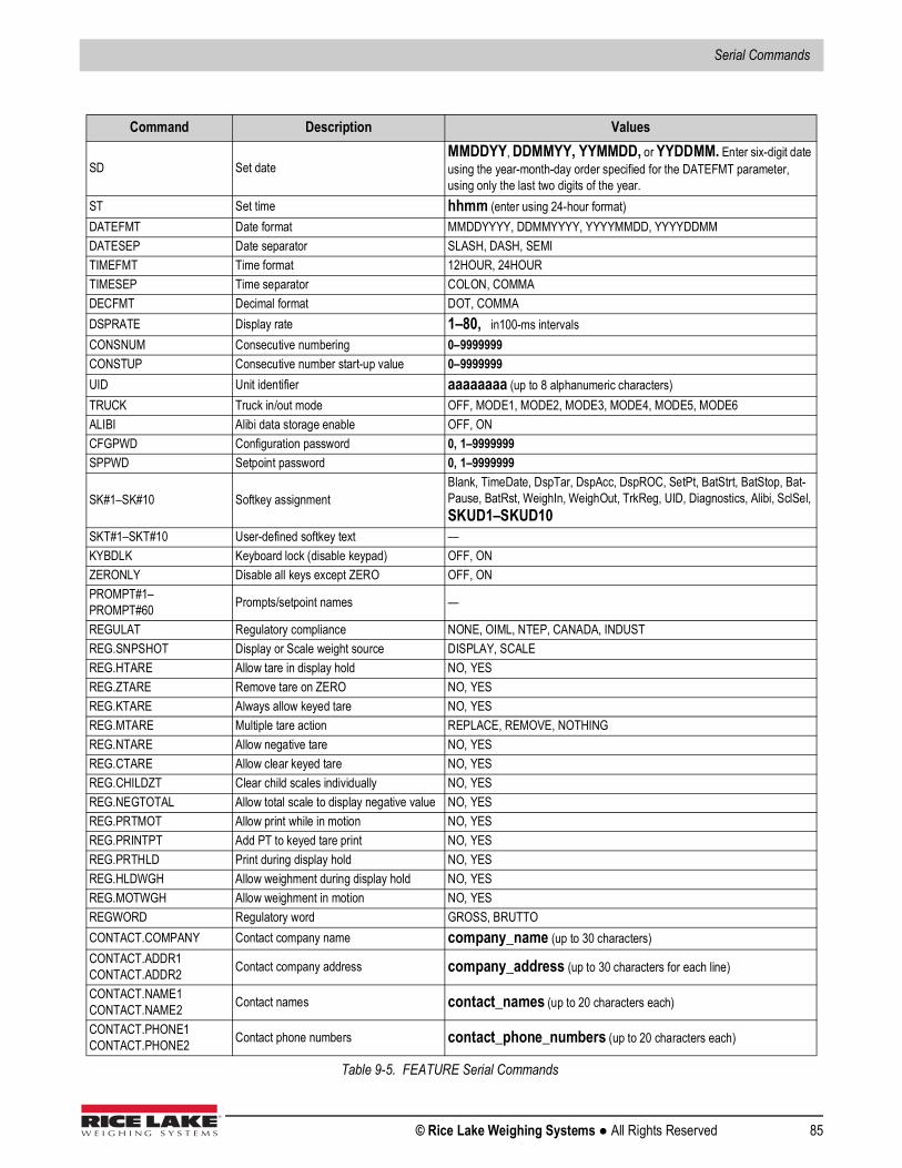
Serial Commands
© Rice Lake Weighing Systems ● All Rights Reserved 85
Command Description Values
SD Set dateMMDDYY, DDMMYY, YYMMDD, or YYDDMM. Enter six-digit date using the year-month-day order specified for the DATEFMT parameter, using only the last two digits of the year.
ST Set time hhmm (enter using 24-hour format)DATEFMT Date format MMDDYYYY, DDMMYYYY, YYYYMMDD, YYYYDDMMDATESEP Date separator SLASH, DASH, SEMITIMEFMT Time format 12HOUR, 24HOURTIMESEP Time separator COLON, COMMADECFMT Decimal format DOT, COMMADSPRATE Display rate 1–80, in100-ms intervalsCONSNUM Consecutive numbering 0–9999999CONSTUP Consecutive number start-up value 0–9999999UID Unit identifier aaaaaaaa (up to 8 alphanumeric characters)TRUCK Truck in/out mode OFF, MODE1, MODE2, MODE3, MODE4, MODE5, MODE6ALIBI Alibi data storage enable OFF, ONCFGPWD Configuration password 0, 1–9999999SPPWD Setpoint password 0, 1–9999999
SK#1–SK#10 Softkey assignmentBlank, TimeDate, DspTar, DspAcc, DspROC, SetPt, BatStrt, BatStop, Bat-Pause, BatRst, WeighIn, WeighOut, TrkReg, UID, Diagnostics, Alibi, SclSel, SKUD1–SKUD10
SKT#1–SKT#10 User-defined softkey text —KYBDLK Keyboard lock (disable keypad) OFF, ONZERONLY Disable all keys except ZERO OFF, ONPROMPT#1–PROMPT#60 Prompts/setpoint names —
REGULAT Regulatory compliance NONE, OIML, NTEP, CANADA, INDUSTREG.SNPSHOT Display or Scale weight source DISPLAY, SCALEREG.HTARE Allow tare in display hold NO, YESREG.ZTARE Remove tare on ZERO NO, YESREG.KTARE Always allow keyed tare NO, YESREG.MTARE Multiple tare action REPLACE, REMOVE, NOTHINGREG.NTARE Allow negative tare NO, YESREG.CTARE Allow clear keyed tare NO, YESREG.CHILDZT Clear child scales individually NO, YESREG.NEGTOTAL Allow total scale to display negative value NO, YESREG.PRTMOT Allow print while in motion NO, YESREG.PRINTPT Add PT to keyed tare print NO, YESREG.PRTHLD Print during display hold NO, YESREG.HLDWGH Allow weighment during display hold NO, YESREG.MOTWGH Allow weighment in motion NO, YESREGWORD Regulatory word GROSS, BRUTTOCONTACT.COMPANY Contact company name company_name (up to 30 characters)CONTACT.ADDR1CONTACT.ADDR2 Contact company address company_address (up to 30 characters for each line)
CONTACT.NAME1CONTACT.NAME2 Contact names contact_names (up to 20 characters each)
CONTACT.PHONE1CONTACT.PHONE2 Contact phone numbers contact_phone_numbers (up to 20 characters each)
Table 9-5. FEATURE Serial Commands
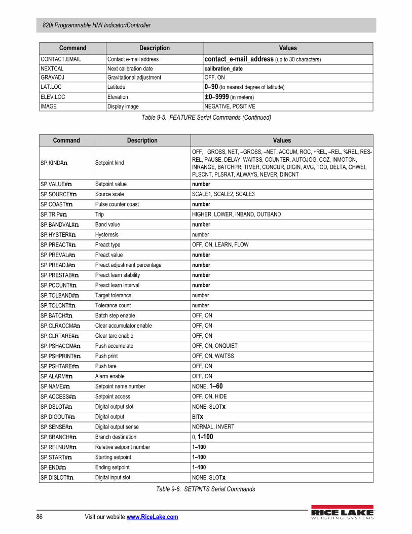
820i Programmable HMI Indicator/Controller
86 Visit our website www.RiceLake.com
CONTACT.EMAIL Contact e-mail address contact_e-mail_address (up to 30 characters)NEXTCAL Next calibration date calibration_dateGRAVADJ Gravitational adjustment OFF, ONLAT.LOC Latitude 0–90 (to nearest degree of latitude)ELEV.LOC Elevation ±0–9999 (in meters)IMAGE Display image NEGATIVE, POSITIVE
Command Description Values
SP.KIND#n Setpoint kind
OFF, GROSS, NET, –GROSS, –NET, ACCUM, ROC, +REL, –REL, %REL, RES-REL, PAUSE, DELAY, WAITSS, COUNTER, AUTOJOG, COZ, INMOTON, INRANGE, BATCHPR, TIMER, CONCUR, DIGIN, AVG, TOD, DELTA, CHWEI, PLSCNT, PLSRAT, ALWAYS, NEVER, DINCNT
SP.VALUE#n Setpoint value numberSP.SOURCE#n Source scale SCALE1, SCALE2, SCALE3SP.COAST#n Pulse counter coast numberSP.TRIP#n Trip HIGHER, LOWER, INBAND, OUTBANDSP.BANDVAL#n Band value numberSP.HYSTER#n Hysteresis numberSP.PREACT#n Preact type OFF, ON, LEARN, FLOWSP.PREVAL#n Preact value numberSP.PREADJ#n Preact adjustment percentage numberSP.PRESTAB#n Preact learn stability numberSP.PCOUNT#n Preact learn interval numberSP.TOLBAND#n Target tolerance numberSP.TOLCNT#n Tolerance count numberSP.BATCH#n Batch step enable OFF, ONSP.CLRACCM#n Clear accumulator enable OFF, ONSP.CLRTARE#n Clear tare enable OFF, ONSP.PSHACCM#n Push accumulate OFF, ON, ONQUIETSP.PSHPRINT#n Push print OFF, ON, WAITSSSP.PSHTARE#n Push tare OFF, ONSP.ALARM#n Alarm enable OFF, ONSP.NAME#n Setpoint name number NONE, 1–60SP.ACCESS#n Setpoint access OFF, ON, HIDESP.DSLOT#n Digital output slot NONE, SLOTxSP.DIGOUT#n Digital output BITxSP.SENSE#n Digital output sense NORMAL, INVERTSP.BRANCH#n Branch destination 0, 1-100SP.RELNUM#n Relative setpoint number 1–100SP.START#n Starting setpoint 1–100SP.END#n Ending setpoint 1–100SP.DISLOT#n Digital input slot NONE, SLOTx
Table 9-6. SETPNTS Serial Commands
Command Description Values
Table 9-5. FEATURE Serial Commands (Continued)
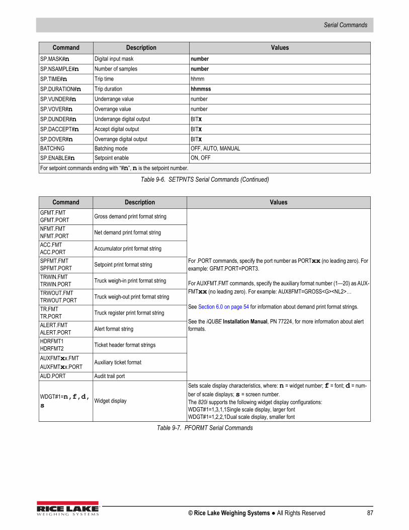
Serial Commands
© Rice Lake Weighing Systems ● All Rights Reserved 87
SP.MASK#n Digital input mask numberSP.NSAMPLE#n Number of samples numberSP.TIME#n Trip time hhmmSP.DURATION#n Trip duration hhmmssSP.VUNDER#n Underrange value numberSP.VOVER#n Overrange value numberSP.DUNDER#n Underrange digital output BITxSP.DACCEPT#n Accept digital output BITxSP.DOVER#n Overrange digital output BITxBATCHNG Batching mode OFF, AUTO, MANUALSP.ENABLE#n Setpoint enable ON, OFFFor setpoint commands ending with “#n”, n is the setpoint number.
Command Description ValuesGFMT.FMTGFMT.PORT Gross demand print format string
For .PORT commands, specify the port number as PORTxx (no leading zero). For example: GFMT.PORT=PORT3.
For AUXFMT.FMT commands, specify the auxiliary format number (1—20) as AUX-FMTxx (no leading zero). For example: AUX8FMT=GROSS<G><NL2>…
See Section 6.0 on page 54 for information about demand print format strings.
See the iQUBE Installation Manual, PN 77224, for more information about alert formats.
NFMT.FMTNFMT.PORT Net demand print format string
ACC.FMTACC.PORT Accumulator print format string
SPFMT.FMTSPFMT.PORT Setpoint print format string
TRWIN.FMTTRWIN.PORT Truck weigh-in print format string
TRWOUT.FMTTRWOUT.PORT Truck weigh-out print format string
TR.FMTTR.PORT Truck register print format string
ALERT.FMTALERT.PORT Alert format string
HDRFMT1HDRFMT2 Ticket header format strings
AUXFMTxx.FMTAUXFMTxx.PORT
Auxiliary ticket format
AUD.PORT Audit trail port
WDGT#1=n,f,d,s
Widget display
Sets scale display characteristics, where: n = widget number; f = font; d = num-ber of scale displays; s = screen number.The 820i supports the following widget display configurations:WDGT#1=1,3,1,1Single scale display, larger fontWDGT#1=1,2,2,1Dual scale display, smaller font
Table 9-7. PFORMT Serial Commands
Command Description Values
Table 9-6. SETPNTS Serial Commands (Continued)
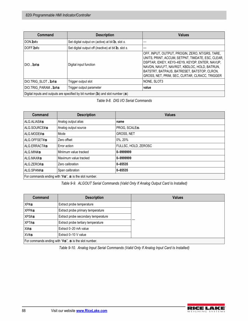
820i Programmable HMI Indicator/Controller
88 Visit our website www.RiceLake.com
Command Description ValuesDON.b#s Set digital output on (active) at bit b, slot s. —DOFF.b#s Set digital output off (inactive) at bit b, slot s. —
DIO.b#s Digital input function
OFF, INPUT, OUTPUT, PROGIN, ZERO, NT/GRS, TARE, UNITS, PRINT, ACCUM, SETPNT, TIMDATE, ESC, CLEAR, DSPTAR, IDKEY, KEY0–KEY9, KEYDP, ENTER, NAVUP, NAVDN, NAVLFT, NAVRGT, KBDLOC, HOLD, BATRUN, BATSTRT, BATPAUS, BATRESET, BATSTOP, CLRCN, GROSS, NET, PRIM, SEC, CLRTAR, CLRACC, TRIGGER
DIO.TRIG_SLOT.b#s Trigger output slot NONE, SLOT3DIO.TRIG_PARAM.b#s Trigger output parameter valueDigital inputs and outputs are specified by bit number (b) and slot number (s)
Table 9-8. DIG I/O Serial Commands
Command Description ValuesALG.ALIAS#s Analog output alias nameALG.SOURCE#s Analog output source PROG, SCALEn ALG.MODE#s Mode GROSS, NETALG.OFFSET#s Zero offset 0%, 20%ALG.ERRACT#s Error action FULLSC, HOLD, ZEROSCALG.MIN#s Minimum value tracked 0–9999999ALG.MAX#s Maximum value tracked 0–9999999ALG.ZERO#s Zero calibration 0–65535ALG.SPAN#s Span calibration 0–65535For commands ending with “#s”, s is the slot number.
Table 9-9. ALGOUT Serial Commands (Valid Only If Analog Output Card Is Installed)
Command Description ValuesXP#s Extract probe temperature
—
XPP#s Extract probe primary temperatureXPS#s Extract probe secondary temperatureXPT#s Extract probe tertiary temperatureXI#s Extract 0–20 mA valueXV#s Extract 0–10 V valueFor commands ending with “#s”, s is the slot number.
Table 9-10. Analog Input Serial Commands (Valid Only If Analog Input Card Is Installed)
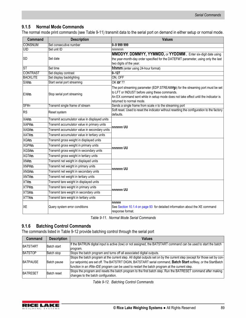
Serial Commands
© Rice Lake Weighing Systems ● All Rights Reserved 89
9.1.5 Normal Mode CommandsThe normal mode print commands (see Table 9-11) transmit data to the serial port on demand in either setup or normal mode.
9.1.6 Batching Control CommandsThe commands listed in Table 9-12 provide batching control through the serial port
Command Description ValuesCONSNUM Set consecutive number 0–9 999 999UID Set unit ID nnnnnnn
SD Set dateMMDDYY, DDMMYY, YYMMDD, or YYDDMM. Enter six-digit date using the year-month-day order specified for the DATEFMT parameter, using only the last two digits of the year.
ST Set time hhmm (enter using 24-hour format)CONTRAST Set display contrast 0–127BACKLITE Set display backlighting ON, OFFSX#n Start serial port streaming OK or ??
The port streaming parameter (EDP.STREAM#p) for the streaming port must be set to LFT or INDUST before using these commands.An EX command sent while in setup mode does not take effect until the indicator is returned to normal mode.
EX#n Stop serial port streaming
SF#n Transmit single frame of stream Sends a single frame from scale n to the streaming port
RS Reset system Soft reset. Used to reset the indicator without resetting the configuration to the factory defaults.
XA#n Transmit accumulator value in displayed units
nnnnnn UUXAP#n Transmit accumulator value in primary unitsXAS#n Transmit accumulator value in secondary unitsXAT#n Transmit accumulator value in tertiary unitsXG#n Transmit gross weight in displayed units
nnnnnn UUXGP#n Transmit gross weight in primary unitsXGS#n Transmit gross weight in secondary unitsXGT#n Transmit gross weight in tertiary unitsXN#n Transmit net weight in displayed units
nnnnnn UUXNP#n Transmit net weight in primary unitsXNS#n Transmit net weight in secondary unitsXNT#n Transmit net weight in tertiary unitsXT#n Transmit tare weight in displayed units
nnnnnn UUXTP#n Transmit tare weight in primary unitsXTS#n Transmit tare weight in secondary unitsXTT#n Transmit tare weight in tertiary units
XE Query system error conditionsnnnnnSee Section 10.1.4 on page 93 for detailed information about the XE command response format.
Table 9-11. Normal Mode Serial Commands
Command Description Values
BATSTART Batch start If the BATRUN digital input is active (low) or not assigned, the BATSTART command can be used to start the batch program.
BATSTOP Batch stop Stops the batch program and turns off all associated digital outputs.
BATPAUSE Batch pauseStops the batch program at the current step. All digital outputs set on by the current step (except for those set by con-cur setpoints) are set off. The BATSTRT DIGIN, BATSTART serial command, Batch Start softkey, or the StartBatch function in an iRite-IDE program can be used to restart the batch program at the current step.
BATRESET Batch reset Stops the program and resets the batch program to the first batch step. Run the BATRESET command after making changes to the batch configuration.
Table 9-12. Batching Control Commands
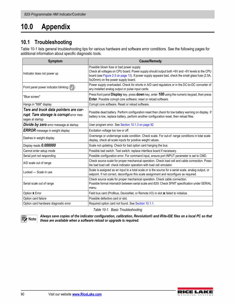
820i Programmable HMI Indicator/Controller
90 Visit our website www.RiceLake.com
10.0 Appendix
10.1 TroubleshootingTable 10-1 lists general troubleshooting tips for various hardware and software error conditions. See the following pages for additional information about specific diagnostic tools.
Always save copies of the indicator configuration, calibration, Revolution® and iRite-IDE files on a local PC so that these are available when a software reload or upgrade is required.
Symptom Cause/Remedy
Indicator does not power up
Possible blown fuse or bad power supply. Check all voltages on CPU board. Power supply should output both +6V and –6V levels to the CPU board (see Figure 2-3 on page 13). If power supply appears bad, check the small glass fuse (2.5A, 5x20mm) on the power supply board.
Front panel power indicator blinking ( )Power supply overloaded. Check for shorts in A/D card regulators or in the DC-to-DC converter of any installed analog output or pulse input cards.
"Blue screen" Press front panel Display key, press down key, enter 100 using the numeric keypad, then press Enter. Possible corrupt core software; reset or reload software.
Hangs in "888" display Corrupt core software. Reset or reload software.Tare and truck data pointers are cor-rupt, Tare storage is corrupt error mes-sages at startup
Possible dead battery. Perform configuration reset then check for low battery warning on display. If battery is low, replace battery, perform another configuration reset, then reload files.
Divide by zero error message at startup User program error. See Section 10.1.3 on page 92ERROR message in weight display Excitation voltage too low or off.
Dashes in weight display Overrange or underrange scale condition. Check scale. For out-of -range conditions in total scale display, check all scale inputs for positive weight values.
Display reads 0.000000 Scale not updating. Check for bad option card hanging the bus.Cannot enter setup mode Possible bad switch. Test switch; replace interface board if necessary.Serial port not responding Possible configuration error. For command input, ensure port INPUT parameter is set to CMD.
A/D scale out of range Check source scale for proper mechanical operation. Check load cell and cable connection. Possi-ble bad load cell: check indicator operation with load cell simulator.
Locked — Scale in use Scale is assigned as an input to a total scale or is the source for a serial scale, analog output, or setpoint. If not correct, deconfigure this scale assignment and reconfigure as required.
Serial scale out of rangeCheck source scale for proper mechanical operation. Check cable connection. Possible format mismatch between serial scale and 820i: Check SFMT specification under SERIAL menu.
Option x Error Field bus card (Profibus, DeviceNet, or Remote I/O) in slot x failed to initialize.Option card failure Possible defective card or slot.Option card hardware diagnostic error Required option card not found. See Section 10.1.1.
Table 10-1. Basic Troubleshooting
Note
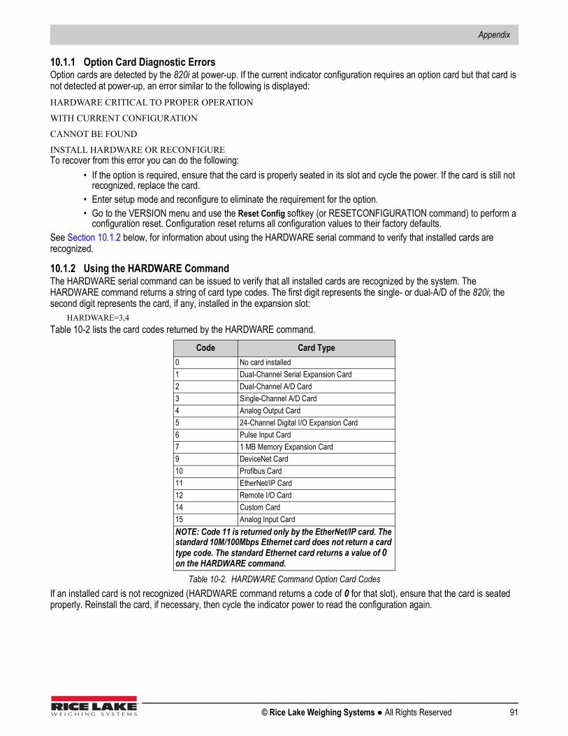
Appendix
© Rice Lake Weighing Systems ● All Rights Reserved 91
10.1.1 Option Card Diagnostic ErrorsOption cards are detected by the 820i at power-up. If the current indicator configuration requires an option card but that card is not detected at power-up, an error similar to the following is displayed:HARDWARE CRITICAL TO PROPER OPERATION
WITH CURRENT CONFIGURATION
CANNOT BE FOUND
INSTALL HARDWARE OR RECONFIGURETo recover from this error you can do the following:
• If the option is required, ensure that the card is properly seated in its slot and cycle the power. If the card is still not recognized, replace the card.
• Enter setup mode and reconfigure to eliminate the requirement for the option.• Go to the VERSION menu and use the Reset Config softkey (or RESETCONFIGURATION command) to perform a
configuration reset. Configuration reset returns all configuration values to their factory defaults.See Section 10.1.2 below, for information about using the HARDWARE serial command to verify that installed cards are recognized.
10.1.2 Using the HARDWARE CommandThe HARDWARE serial command can be issued to verify that all installed cards are recognized by the system. The HARDWARE command returns a string of card type codes. The first digit represents the single- or dual-A/D of the 820i; the second digit represents the card, if any, installed in the expansion slot:
HARDWARE=3,4Table 10-2 lists the card codes returned by the HARDWARE command.
If an installed card is not recognized (HARDWARE command returns a code of 0 for that slot), ensure that the card is seated properly. Reinstall the card, if necessary, then cycle the indicator power to read the configuration again.
Code Card Type0 No card installed1 Dual-Channel Serial Expansion Card2 Dual-Channel A/D Card3 Single-Channel A/D Card4 Analog Output Card5 24-Channel Digital I/O Expansion Card6 Pulse Input Card7 1 MB Memory Expansion Card9 DeviceNet Card10 Profibus Card11 EtherNet/IP Card12 Remote I/O Card14 Custom Card15 Analog Input CardNOTE: Code 11 is returned only by the EtherNet/IP card. The standard 10M/100Mbps Ethernet card does not return a card type code. The standard Ethernet card returns a value of 0 on the HARDWARE command.
Table 10-2. HARDWARE Command Option Card Codes

820i Programmable HMI Indicator/Controller
92 Visit our website www.RiceLake.com
10.1.3 User Program Diagnostic ErrorsFaulty user programs can cause critical errors that are detected by the 820i at power-up. The following error message is caused by a user program attempting to divide by zero:A CRITICAL USER PROGRAM ERROR
HAS BEEN DETECTED
DIVIDE BY ZERO
SYSTEM RESET IS REQUIREDTo recover from this error you can do the following:
• Cycle the indicator power to reset the user program.• Correct the iRite-IDE program to eliminate the divide by zero operation. Recompile the program, then download the
corrected program to the indicator.If technical assistance is required, contact Rice Lake Weighing Systems technical support.
Diagnostic Boot ProcedureIf a user program causes an error in the start-up handler, press and hold the setup switch while cycling power to the 820i to place the indicator in setup mode. Use Revolution monitor mode to send the PCLR command erase clear the user program. If the error is still not cleared, perform the following diagnostic boot procedure.
1. Disconnect power to the 820i. 2. Connect the serial port of a PC with Revolution installed to port 2 of the 820i. 3. Open the indicator enclosure and place a jumper across the boot mode pins (see Figure 2-3). 4. Power up the 820i. The indicator will stall at the diagnostic monitor.5. Start Revolution and enter monitor mode, then type BOOT.6. Use the indicator setup switch to enter setup mode.7. Remove the jumper from SW1. 8. From monitor mode, enter the RESETCONFIGURATION command.
Determine the cause of the startup handler error, make program corrections, then reload the corrected user program and test.

Appendix
© Rice Lake Weighing Systems ● All Rights Reserved 93
10.1.4 Using the XE Serial CommandThe XE serial command can be used to remotely query the 820i for the error conditions shown on the front panel. The XE command returns a decimal number representing any existing error conditions. For multi-scale applications, the value returned by the XE command represents all error conditions, if any, present on all configured scales.If more than one error condition exists, the number returned is the sum of the values representing the error conditions (see Table 10-3). For example, if both a tare error (TAREERR, 65536) and a truck database checksum error (ETRUCKERR, 8192) have occurred, the XE command returns the value 73728, representing the sum of those two error conditions.
Error Code Value DescriptionVIRGERR 1 Virgin errorPARMCHKERR 2 Configuration checksum errorLOADCHKERR 4 Calibration checksum errorPRINTCHKERR 8 Print format checksum errorENVRAMERR 16 General NVRAM errorENVCRC1ERR 32
Setpoint NVRAM data error
ENVCRC2ERR 64ENVCRC3ERR 128ENVCRC4ERR 256ENVCRC5ERR 512ENVCRC6ERR 1024ENVCRC7ERR 2056ENVCRC8ERR 4096ETRUCKERR 8192 Truck database checksum errorGRAVERR 16384 Gravity calibration errorADPHYSICALERR 32768 A/D physical errorTAREERR 65536 Tare checksum errorSTRINGERR 262144 String program errorPOWER_FAIL 524288 Power failureRTCERR 1048576 Real time clock error
Table 10-3. Error Codes Returned on XE Command
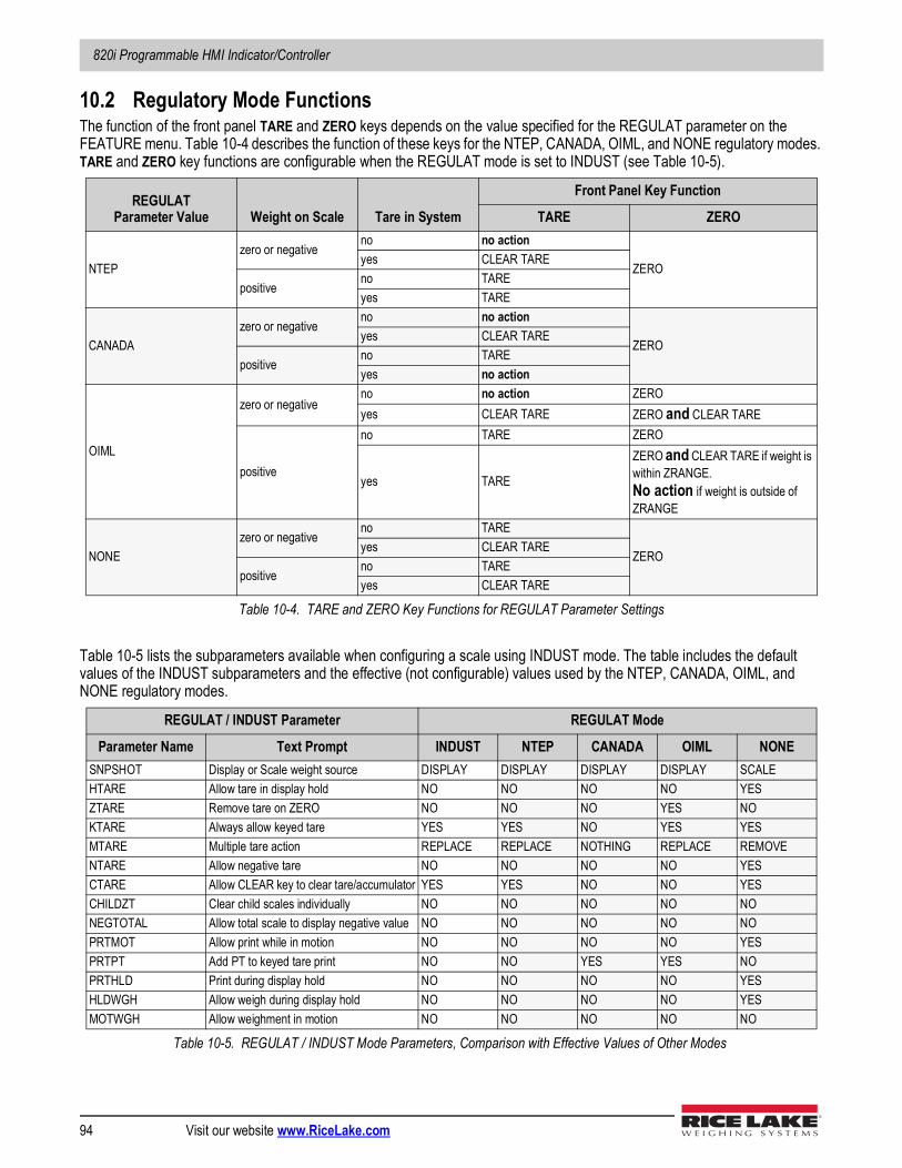
820i Programmable HMI Indicator/Controller
94 Visit our website www.RiceLake.com
10.2 Regulatory Mode FunctionsThe function of the front panel TARE and ZERO keys depends on the value specified for the REGULAT parameter on the FEATURE menu. Table 10-4 describes the function of these keys for the NTEP, CANADA, OIML, and NONE regulatory modes. TARE and ZERO key functions are configurable when the REGULAT mode is set to INDUST (see Table 10-5).
Table 10-5 lists the subparameters available when configuring a scale using INDUST mode. The table includes the default values of the INDUST subparameters and the effective (not configurable) values used by the NTEP, CANADA, OIML, and NONE regulatory modes.
REGULATParameter Value Weight on Scale Tare in System
Front Panel Key Function
TARE ZERO
NTEPzero or negative
no no action
ZEROyes CLEAR TARE
positiveno TAREyes TARE
CANADAzero or negative
no no action
ZEROyes CLEAR TARE
positiveno TAREyes no action
OIML
zero or negativeno no action ZEROyes CLEAR TARE ZERO and CLEAR TARE
positive
no TARE ZERO
yes TARE
ZERO and CLEAR TARE if weight is within ZRANGE.No action if weight is outside of ZRANGE
NONEzero or negative
no TARE
ZEROyes CLEAR TARE
positiveno TAREyes CLEAR TARE
Table 10-4. TARE and ZERO Key Functions for REGULAT Parameter Settings
REGULAT / INDUST Parameter REGULAT Mode
Parameter Name Text Prompt INDUST NTEP CANADA OIML NONESNPSHOT Display or Scale weight source DISPLAY DISPLAY DISPLAY DISPLAY SCALEHTARE Allow tare in display hold NO NO NO NO YESZTARE Remove tare on ZERO NO NO NO YES NOKTARE Always allow keyed tare YES YES NO YES YESMTARE Multiple tare action REPLACE REPLACE NOTHING REPLACE REMOVENTARE Allow negative tare NO NO NO NO YESCTARE Allow CLEAR key to clear tare/accumulator YES YES NO NO YESCHILDZT Clear child scales individually NO NO NO NO NONEGTOTAL Allow total scale to display negative value NO NO NO NO NOPRTMOT Allow print while in motion NO NO NO NO YESPRTPT Add PT to keyed tare print NO NO YES YES NOPRTHLD Print during display hold NO NO NO NO YESHLDWGH Allow weigh during display hold NO NO NO NO YESMOTWGH Allow weighment in motion NO NO NO NO NO
Table 10-5. REGULAT / INDUST Mode Parameters, Comparison with Effective Values of Other Modes
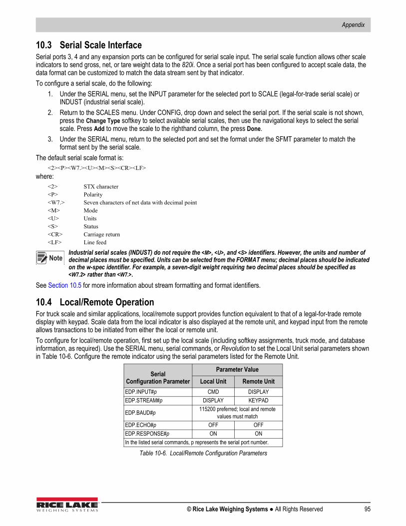
Appendix
© Rice Lake Weighing Systems ● All Rights Reserved 95
10.3 Serial Scale InterfaceSerial ports 3, 4 and any expansion ports can be configured for serial scale input. The serial scale function allows other scale indicators to send gross, net, or tare weight data to the 820i. Once a serial port has been configured to accept scale data, the data format can be customized to match the data stream sent by that indicator.To configure a serial scale, do the following:
1. Under the SERIAL menu, set the INPUT parameter for the selected port to SCALE (legal-for-trade serial scale) or INDUST (industrial serial scale).
2. Return to the SCALES menu. Under CONFIG, drop down and select the serial port. If the serial scale is not shown, press the Change Type softkey to select available serial scales, then use the navigational keys to select the serial scale. Press Add to move the scale to the righthand column, the press Done.
3. Under the SERIAL menu, return to the selected port and set the format under the SFMT parameter to match the format sent by the serial scale.
The default serial scale format is:<2><P><W7.><U><M><S><CR><LF>
where:<2> STX character<P> Polarity<W7.> Seven characters of net data with decimal point<M> Mode<U> Units<S> Status<CR> Carriage return<LF> Line feed
Industrial serial scales (INDUST) do not require the <M>, <U>, and <S> identifiers. However, the units and number of decimal places must be specified. Units can be selected from the FORMAT menu; decimal places should be indicated on the w-spec identifier. For example, a seven-digit weight requiring two decimal places should be specified as <W7.2> rather than <W7.>.
See Section 10.5 for more information about stream formatting and format identifiers.
10.4 Local/Remote OperationFor truck scale and similar applications, local/remote support provides function equivalent to that of a legal-for-trade remote display with keypad. Scale data from the local indicator is also displayed at the remote unit, and keypad input from the remote allows transactions to be initiated from either the local or remote unit.To configure for local/remote operation, first set up the local scale (including softkey assignments, truck mode, and database information, as required). Use the SERIAL menu, serial commands, or Revolution to set the Local Unit serial parameters shown in Table 10-6. Configure the remote indicator using the serial parameters listed for the Remote Unit.
SerialConfiguration Parameter
Parameter Value
Local Unit Remote UnitEDP.INPUT#p CMD DISPLAYEDP.STREAM#p DISPLAY KEYPAD
EDP.BAUD#p 115200 preferred; local and remote values must match
EDP.ECHO#p OFF OFFEDP.RESPONSE#p ON ONIn the listed serial commands, p represents the serial port number.
Table 10-6. Local/Remote Configuration Parameters
Note
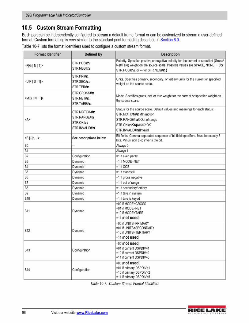
820i Programmable HMI Indicator/Controller
96 Visit our website www.RiceLake.com
10.5 Custom Stream FormattingEach port can be independently configured to stream a default frame format or can be customized to stream a user-defined format. Custom formatting is very similar to the standard print formatting described in Section 6.0. Table 10-7 lists the format identifiers used to configure a custom stream format.
Format Identifier Defined By Description
<P[G | N | T]> STR.POS#nSTR.NEG#n
Polarity. Specifies positive or negative polarity for the current or specified (Gross/Net/Tare) weight on the source scale. Possible values are SPACE, NONE, + (for STR.POS#n), or – (for STR.NEG#n)
<U[P | S | T]>STR.PRI#nSTR.SEC#nSTR.TER#n
Units. Specifies primary, secondary, or tertiary units for the current or specified weight on the source scale.
<M[G | N | T]>STR.GROSS#nSTR.NET#nSTR.TARE#n
Mode. Specifies gross, net, or tare weight for the current or specified weight on the source scale.
<S>
STR.MOTION#nSTR.RANGE#nSTR.OK#nSTR.INVALID#n
Status for the source scale. Default values and meanings for each status:STR.MOTION#nMIn motionSTR.RANGE#nOOut of rangeSTR.OK#n<space>OKSTR.INVALID#nIInvalid
<B [–]n,…> See descriptions below Bit fields. Comma-separated sequence of bit field specifiers. Must be exactly 8 bits. Minus sign ([–]) inverts the bit.
B0 — Always 0B1 — Always 1B2 Configuration =1 if even parityB3 Dynamic =1 if MODE=NETB4 Dynamic =1 if COZB5 Dynamic =1 if standstillB6 Dynamic =1 if gross negativeB7 Dynamic =1 if out of rangeB8 Dynamic =1 if secondary/tertiaryB9 Dynamic =1 if tare in systemB10 Dynamic =1 if tare is keyed
B11 Dynamic
=00 if MODE=GROSS=01 if MODE=NET=10 if MODE=TARE=11 (not used)
B12 Dynamic
=00 if UNITS=PRIMARY=01 if UNITS=SECONDARY=10 if UNITS=TERTIARY=11 (not used)
B13 Configuration
=00 (not used)=01 if current DSPDIV=1=10 if current DSPDIV=2=11 if current DSPDIV=5
B14 Configuration
=00 (not used)=01 if primary DSPDIV=1=10 if primary DSPDIV=2=11 if primary DSPDIV=5
Table 10-7. Custom Stream Format Identifiers
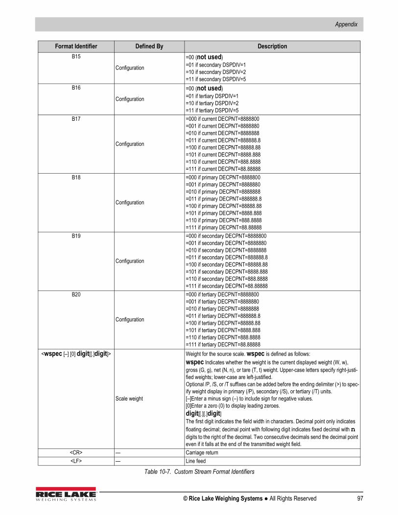
Appendix
© Rice Lake Weighing Systems ● All Rights Reserved 97
B15
Configuration
=00 (not used)=01 if secondary DSPDIV=1=10 if secondary DSPDIV=2=11 if secondary DSPDIV=5
B16
Configuration
=00 (not used)=01 if tertiary DSPDIV=1=10 if tertiary DSPDIV=2=11 if tertiary DSPDIV=5
B17
Configuration
=000 if current DECPNT=8888800=001 if current DECPNT=8888880=010 if current DECPNT=8888888=011 if current DECPNT=888888.8=100 if current DECPNT=88888.88=101 if current DECPNT=8888.888=110 if current DECPNT=888.8888=111 if current DECPNT=88.88888
B18
Configuration
=000 if primary DECPNT=8888800=001 if primary DECPNT=8888880=010 if primary DECPNT=8888888=011 if primary DECPNT=888888.8=100 if primary DECPNT=88888.88=101 if primary DECPNT=8888.888=110 if primary DECPNT=888.8888=111 if primary DECPNT=88.88888
B19
Configuration
=000 if secondary DECPNT=8888800=001 if secondary DECPNT=8888880=010 if secondary DECPNT=8888888=011 if secondary DECPNT=888888.8=100 if secondary DECPNT=88888.88=101 if secondary DECPNT=8888.888=110 if secondary DECPNT=888.8888=111 if secondary DECPNT=88.88888
B20
Configuration
=000 if tertiary DECPNT=8888800=001 if tertiary DECPNT=8888880=010 if tertiary DECPNT=8888888=011 if tertiary DECPNT=888888.8=100 if tertiary DECPNT=88888.88=101 if tertiary DECPNT=8888.888=110 if tertiary DECPNT=888.8888=111 if tertiary DECPNT=88.88888
<wspec [–] [0] digit[[.]digit]>
Scale weight
Weight for the source scale. wspec is defined as follows:wspec Indicates whether the weight is the current displayed weight (W, w), gross (G, g), net (N, n), or tare (T, t) weight. Upper-case letters specify right-justi-fied weights; lower-case are left-justified.Optional /P, /S, or /T suffixes can be added before the ending delimiter (>) to spec-ify weight display in primary (/P), secondary (/S), or tertiary (/T) units.[–]Enter a minus sign (–) to include sign for negative values.[0]Enter a zero (0) to display leading zeroes.digit[[.][.]digit]The first digit indicates the field width in characters. Decimal point only indicates floating decimal; decimal point with following digit indicates fixed decimal with n digits to the right of the decimal. Two consecutive decimals send the decimal point even if it falls at the end of the transmitted weight field.
<CR> — Carriage return<LF> — Line feed
Format Identifier Defined By Description
Table 10-7. Custom Stream Format Identifiers
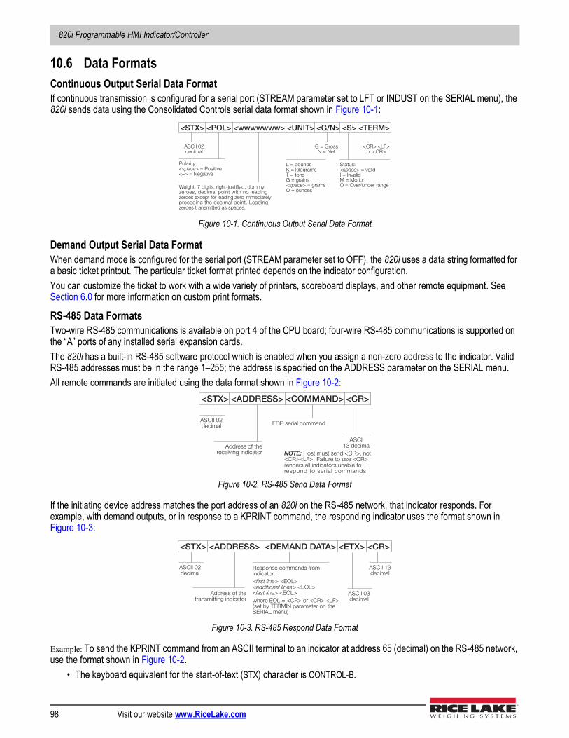
820i Programmable HMI Indicator/Controller
98 Visit our website www.RiceLake.com
10.6 Data FormatsContinuous Output Serial Data FormatIf continuous transmission is configured for a serial port (STREAM parameter set to LFT or INDUST on the SERIAL menu), the 820i sends data using the Consolidated Controls serial data format shown in Figure 10-1:
Figure 10-1. Continuous Output Serial Data Format
Demand Output Serial Data FormatWhen demand mode is configured for the serial port (STREAM parameter set to OFF), the 820i uses a data string formatted for a basic ticket printout. The particular ticket format printed depends on the indicator configuration. You can customize the ticket to work with a wide variety of printers, scoreboard displays, and other remote equipment. See Section 6.0 for more information on custom print formats.
RS-485 Data FormatsTwo-wire RS-485 communications is available on port 4 of the CPU board; four-wire RS-485 communications is supported on the “A” ports of any installed serial expansion cards.The 820i has a built-in RS-485 software protocol which is enabled when you assign a non-zero address to the indicator. Valid RS-485 addresses must be in the range 1–255; the address is specified on the ADDRESS parameter on the SERIAL menu.All remote commands are initiated using the data format shown in Figure 10-2:
Figure 10-2. RS-485 Send Data Format
If the initiating device address matches the port address of an 820i on the RS-485 network, that indicator responds. For example, with demand outputs, or in response to a KPRINT command, the responding indicator uses the format shown in Figure 10-3:
Figure 10-3. RS-485 Respond Data Format
Example: To send the KPRINT command from an ASCII terminal to an indicator at address 65 (decimal) on the RS-485 network, use the format shown in Figure 10-2.
• The keyboard equivalent for the start-of-text (STX) character is CONTROL-B.
<STX> <POL> <wwwwwww> <UNIT> <G/N> <S> <TERM>
ASCII 02 decimal
Polarity: <space> = Positive <–> = Negative
Weight: 7 digits, right-justified, dummy zeroes, decimal point with no leading zeroes except for leading zero immediately preceding the decimal point. Leading zeroes transmitted as spaces.
L = pounds K = kilograms T = tons G = grains <space> = grams O = ounces
G = Gross N = Net
Status: <space> = valid I = Invalid M = Motion O = Over/under range
<CR> <LF> or <CR>
<STX> <ADDRESS> <COMMAND> <CR>
ASCII 02 decimal
Address of the r eceiving indicator
EDP serial command
NOTE: Host must send <CR>, not <CR><LF>. Failure to use <CR> renders all indicators unable to respond to serial commands
ASCII 13 decimal
<STX> <ADDRESS> <DEMAND DATA> <ETX> <CR>
ASCII 02 decimal
Addr ess of the transmitting indicator
Response commands from indicator:
< first line > <EOL> < additional lines > <EOL> < last line > <EOL>
where EOL = <CR> or <CR> <LF> (set by TERMIN parameter on the SERIAL menu)
ASCII 13 decimal
ASCII 03 decimal
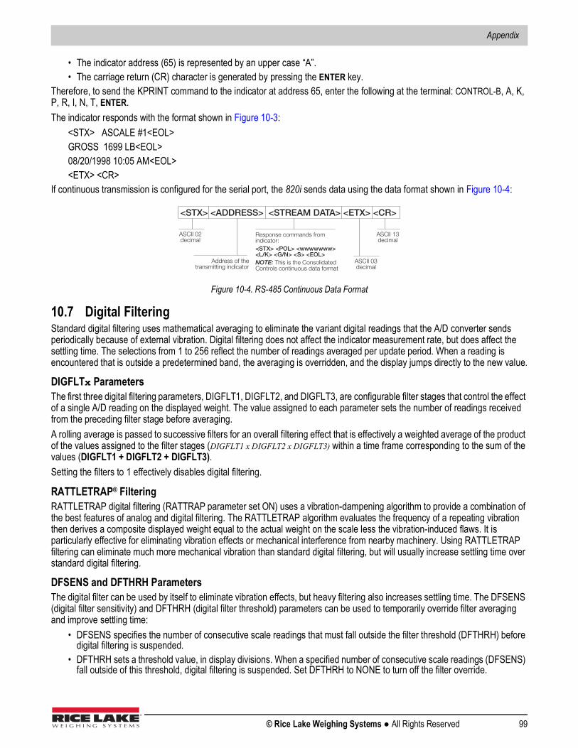
Appendix
© Rice Lake Weighing Systems ● All Rights Reserved 99
• The indicator address (65) is represented by an upper case “A”.• The carriage return (CR) character is generated by pressing the ENTER key.
Therefore, to send the KPRINT command to the indicator at address 65, enter the following at the terminal: CONTROL-B, A, K, P, R, I, N, T, ENTER.The indicator responds with the format shown in Figure 10-3:
<STX> ASCALE #1<EOL> GROSS 1699 LB<EOL>08/20/1998 10:05 AM<EOL><ETX> <CR>
If continuous transmission is configured for the serial port, the 820i sends data using the data format shown in Figure 10-4:
Figure 10-4. RS-485 Continuous Data Format
10.7 Digital FilteringStandard digital filtering uses mathematical averaging to eliminate the variant digital readings that the A/D converter sends periodically because of external vibration. Digital filtering does not affect the indicator measurement rate, but does affect the settling time. The selections from 1 to 256 reflect the number of readings averaged per update period. When a reading is encountered that is outside a predetermined band, the averaging is overridden, and the display jumps directly to the new value.
DIGFLTx ParametersThe first three digital filtering parameters, DIGFLT1, DIGFLT2, and DIGFLT3, are configurable filter stages that control the effect of a single A/D reading on the displayed weight. The value assigned to each parameter sets the number of readings received from the preceding filter stage before averaging. A rolling average is passed to successive filters for an overall filtering effect that is effectively a weighted average of the product of the values assigned to the filter stages (DIGFLT1 x DIGFLT2 x DIGFLT3) within a time frame corresponding to the sum of the values (DIGFLT1 + DIGFLT2 + DIGFLT3).Setting the filters to 1 effectively disables digital filtering.
RATTLETRAP® FilteringRATTLETRAP digital filtering (RATTRAP parameter set ON) uses a vibration-dampening algorithm to provide a combination of the best features of analog and digital filtering. The RATTLETRAP algorithm evaluates the frequency of a repeating vibration then derives a composite displayed weight equal to the actual weight on the scale less the vibration-induced flaws. It is particularly effective for eliminating vibration effects or mechanical interference from nearby machinery. Using RATTLETRAP filtering can eliminate much more mechanical vibration than standard digital filtering, but will usually increase settling time over standard digital filtering.
DFSENS and DFTHRH ParametersThe digital filter can be used by itself to eliminate vibration effects, but heavy filtering also increases settling time. The DFSENS (digital filter sensitivity) and DFTHRH (digital filter threshold) parameters can be used to temporarily override filter averaging and improve settling time:
• DFSENS specifies the number of consecutive scale readings that must fall outside the filter threshold (DFTHRH) before digital filtering is suspended.
• DFTHRH sets a threshold value, in display divisions. When a specified number of consecutive scale readings (DFSENS) fall outside of this threshold, digital filtering is suspended. Set DFTHRH to NONE to turn off the filter override.
Response commands from indicator:
<STX> <POL> <wwwwwww> <L/K> <G/N> <S> <EOL> NOTE: This is the Consolidated Controls continuous data format
<STX> <ADDRESS> <STREAM DATA> <ETX> <CR>
ASCII 02 decimal
Address of the transmitting indicator
ASCII 13 decimal
ASCII 03 decimal

820i Programmable HMI Indicator/Controller
100 Visit our website www.RiceLake.com
Setting the Digital Filter ParametersFine-tuning the digital filter parameters greatly improves indicator performance in heavy-vibration environments. Use the following procedure to determine vibration effects on the scale and optimize the digital filtering configuration.
1. In setup mode, set the digital filter parameters (DIGFLT1–DIGFLT3) to 1. Set DFTHRH to NONE. Return indicator to normal mode.
2. Remove all weight from the scale, then watch the indicator display to determine the magnitude of vibration effects on the scale. Record the weight below which all but a few readings fall. This value is used to calculate the DFTHRH parameter value in Step 4.For example, if a heavy-capacity scale (10000 x 5 lb) produces vibration-related readings of up to 50 lb, with occasional spikes to 75 lb, record 50 lb as the threshold weight value.
3. Place the indicator in setup mode and set the DIGFLTx parameters to eliminate the vibration effects on the scale. (Leave DFTHRH set to NONE.) Find the lowest effective value for the DIGFLTx parameters.
4. Calculate the DFTHRH parameter value by converting the weight value recorded in Step 2 to display divisions:threshold_weight_value / display_divisions
In the example in Step 2, with a threshold weight value of 50 lb and a display divisions value of 5 lb: 50 / 5 = 10. DFTHRH should be set to 10D for this example.
5. Finally, set the DFSENS parameter high enough to ignore transient peaks. Longer transients (typically caused by lower vibration frequencies) will cause more consecutive out-of-band readings, so DFSENS should be set higher to counter low frequency transients.Reconfigure as necessary to find the lowest effective value for the DFSENS parameter.
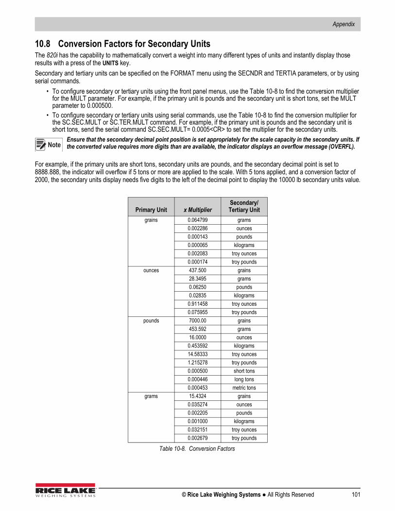
Appendix
© Rice Lake Weighing Systems ● All Rights Reserved 101
10.8 Conversion Factors for Secondary UnitsThe 820i has the capability to mathematically convert a weight into many different types of units and instantly display those results with a press of the UNITS key. Secondary and tertiary units can be specified on the FORMAT menu using the SECNDR and TERTIA parameters, or by using serial commands.
• To configure secondary or tertiary units using the front panel menus, use the Table 10-8 to find the conversion multiplier for the MULT parameter. For example, if the primary unit is pounds and the secondary unit is short tons, set the MULT parameter to 0.000500.
• To configure secondary or tertiary units using serial commands, use the Table 10-8 to find the conversion multiplier for the SC.SEC.MULT or SC.TER.MULT command. For example, if the primary unit is pounds and the secondary unit is short tons, send the serial command SC.SEC.MULT= 0.0005<CR> to set the multiplier for the secondary units.
Ensure that the secondary decimal point position is set appropriately for the scale capacity in the secondary units. If the converted value requires more digits than are available, the indicator displays an overflow message (OVERFL).
For example, if the primary units are short tons, secondary units are pounds, and the secondary decimal point is set to 8888.888, the indicator will overflow if 5 tons or more are applied to the scale. With 5 tons applied, and a conversion factor of 2000, the secondary units display needs five digits to the left of the decimal point to display the 10000 lb secondary units value.
Primary Unit x MultiplierSecondary/Tertiary Unit
grains 0.064799 grams0.002286 ounces0.000143 pounds0.000065 kilograms0.002083 troy ounces0.000174 troy pounds
ounces 437.500 grains28.3495 grams0.06250 pounds0.02835 kilograms
0.911458 troy ounces0.075955 troy pounds
pounds 7000.00 grains453.592 grams16.0000 ounces0.453592 kilograms14.58333 troy ounces1.215278 troy pounds0.000500 short tons0.000446 long tons0.000453 metric tons
grams 15.4324 grains0.035274 ounces0.002205 pounds0.001000 kilograms0.032151 troy ounces0.002679 troy pounds
Table 10-8. Conversion Factors
Note
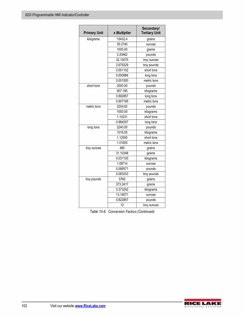
820i Programmable HMI Indicator/Controller
102 Visit our website www.RiceLake.com
kilograms 15432.4 grains35.2740 ounces1000.00 grams2.20462 pounds32.15075 troy ounces2.679229 troy pounds0.001102 short tons0.000984 long tons0.001000 metric tons
short tons 2000.00 pounds907.185 kilograms
0.892857 long tons0.907185 metric tons
metric tons 2204.62 pounds1000.00 kilograms1.10231 short tons
0.984207 long tonslong tons 2240.00 pounds
1016.05 kilograms1.12000 short tons1.01605 metric tons
troy ounces 480 grains31.10348 grams0.031103 kilograms1.09714 ounces0.068571 pounds0.083333 troy pounds
troy pounds 5760 grains373.2417 grams0.373242 kilograms13.16571 ounces0.822857 pounds
12 troy ounces
Primary Unit x MultiplierSecondary/Tertiary Unit
Table 10-8. Conversion Factors (Continued)
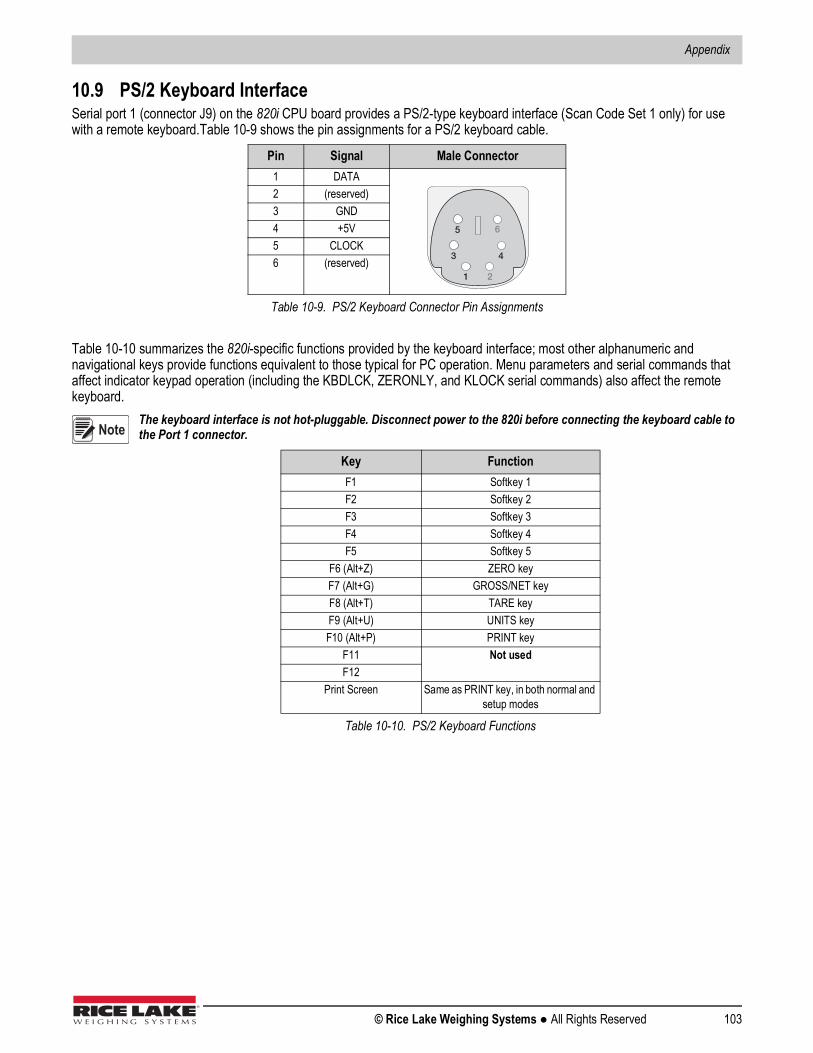
Appendix
© Rice Lake Weighing Systems ● All Rights Reserved 103
10.9 PS/2 Keyboard InterfaceSerial port 1 (connector J9) on the 820i CPU board provides a PS/2-type keyboard interface (Scan Code Set 1 only) for use with a remote keyboard.Table 10-9 shows the pin assignments for a PS/2 keyboard cable.
Table 10-10 summarizes the 820i-specific functions provided by the keyboard interface; most other alphanumeric and navigational keys provide functions equivalent to those typical for PC operation. Menu parameters and serial commands that affect indicator keypad operation (including the KBDLCK, ZERONLY, and KLOCK serial commands) also affect the remote keyboard.
The keyboard interface is not hot-pluggable. Disconnect power to the 820i before connecting the keyboard cable to the Port 1 connector.
Pin Signal Male Connector1 DATA2 (reserved)3 GND4 +5V5 CLOCK6 (reserved)
Table 10-9. PS/2 Keyboard Connector Pin Assignments
Key FunctionF1 Softkey 1F2 Softkey 2F3 Softkey 3F4 Softkey 4F5 Softkey 5
F6 (Alt+Z) ZERO keyF7 (Alt+G) GROSS/NET keyF8 (Alt+T) TARE keyF9 (Alt+U) UNITS keyF10 (Alt+P) PRINT key
F11 Not usedF12
Print Screen Same as PRINT key, in both normal and setup modes
Table 10-10. PS/2 Keyboard Functions
1 2
3 4
5 6
Note

820i Programmable HMI Indicator/Controller
104 Visit our website www.RiceLake.com
10.10 Audit Trail SupportAudit trail support provides tracking information for configuration and calibration events. A separate calibration counter is provided for each scale; a single configuration counter tracks all configuration changes.To prevent potential misuse, unsaved configuration or calibration changes (those followed by an Exit, rather than Save and Exit) are counted as change events; restoration of the previous saved configuration or calibration is also counted.
10.10.1 Displaying Audit Trail InformationTo display audit trail information, press and hold the Gross/Net key for several seconds. Various audit trail information screens can then be accessed by pressing the front panel number keys (1–5 and 0). The exact format of each screen depends on the regulatory agency specified for the REGULAT (FEATURE menu) parameter.The initial screen shown when entering the audit trail display (or whenever the 1 key is pressed while showing audit trail information) shows the legally relevant (LR) version number (software version for the code that provides audit trail information), a calibration count and, if REGULAT=NTEP, a configuration count. Press 2 to show the configuration count display. This display shows the number of times the system has been configured, the date and time of the last configuration event, and the before and after information for the most recent change of the system date and time.Press the Down key to show the number of weighments, number of configuration events, number of calibrations, and the date and time of the most recent calibration for the first configured scale. Continue pressing the Down key to cycle through the information for all configured scales.Press 3 to show the number and the most recent date and time of power-on events, power-on configuration changes, and user program loads. (Power-on configuration changes are those that restore a previous configuration after reconfiguring or recalibrating then pressing Exit, rather than Save and Exit.) Use the Down key to show the number of power-on calibration events for all configured scales.Press 4 to show the number of times the OEM version number has been changed, and the date and time of the most recent change.Press 5 to show the number of times the configuration has been reset, the date and time of the most recent reset, and the indicator EIN number.Press 0 to show the indicator and LR software versions.When done, press the Gross/Net key to exit the audit trail displays.
10.10.2 Printing Audit Trail InformationAudit trail information can be printed by pressing the PRINT key while displaying the audit trail or by sending the DUMPAUDIT serial command. Audit trail information is sent to the port specified on the AUD.PORT serial command or by the AUDFMT parameter (PFORMT menu).
Printed audit trail information contains data for all scales, whether configured or not, that can be supported by the indicator. Displayed audit trail information shows data only for currently configured scales.Note
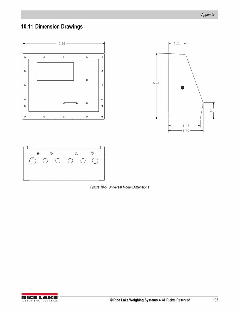
Appendix
© Rice Lake Weighing Systems ● All Rights Reserved 105
10.11 Dimension Drawings
Figure 10-5. Universal Model Dimensions
820i Programmable HMI Indicator/Controller
106 Visit our website www.RiceLake.com
10.12 Printed InformationSystem Manuals
• 820i Installation Manual, PN 93018Enclosures
• 820i Panel Mount Installation Instructions, PN 95304Option Cards (820i/920i)
• Analog Output Card Installation Instructions, PN 69089• 24-Channel Digital I/O Expansion Card Installation Instructions, PN 69087• Dual-Channel Serial Expansion Card Installation Instructions, PN 69088• Pulse Input Card Installation Instructions, PN 69086• Memory Expansion Card Installation Instructions, PN 69085• Analog Input Card with Thermocouple Input Installation Instructions, PN 88110
Communications Options (520/820i/920i)• DeviceNet™ Interface Installation and Programming Manual, PN 69949• Profibus® DP Interface Installation and Programming Manual, PN 69948• Allen-Bradley® Remote I/O Interface Installation and Programming Manual, PN 69950• Ethernet Communications Card Installation Instructions, PN 72117• EtherNet/IP Communications Card Installation Instructions, PN 88537• USB Interface Card Installation Instructions, PN 95490
iQUBE Digital Diagnostic Junction Box• iQUBE Installation Manual, PN 77224
White Papers• Using Ferrite Cores to Suppress Electromagnetic Interference - For Digital Weight Indicators, PN 117085
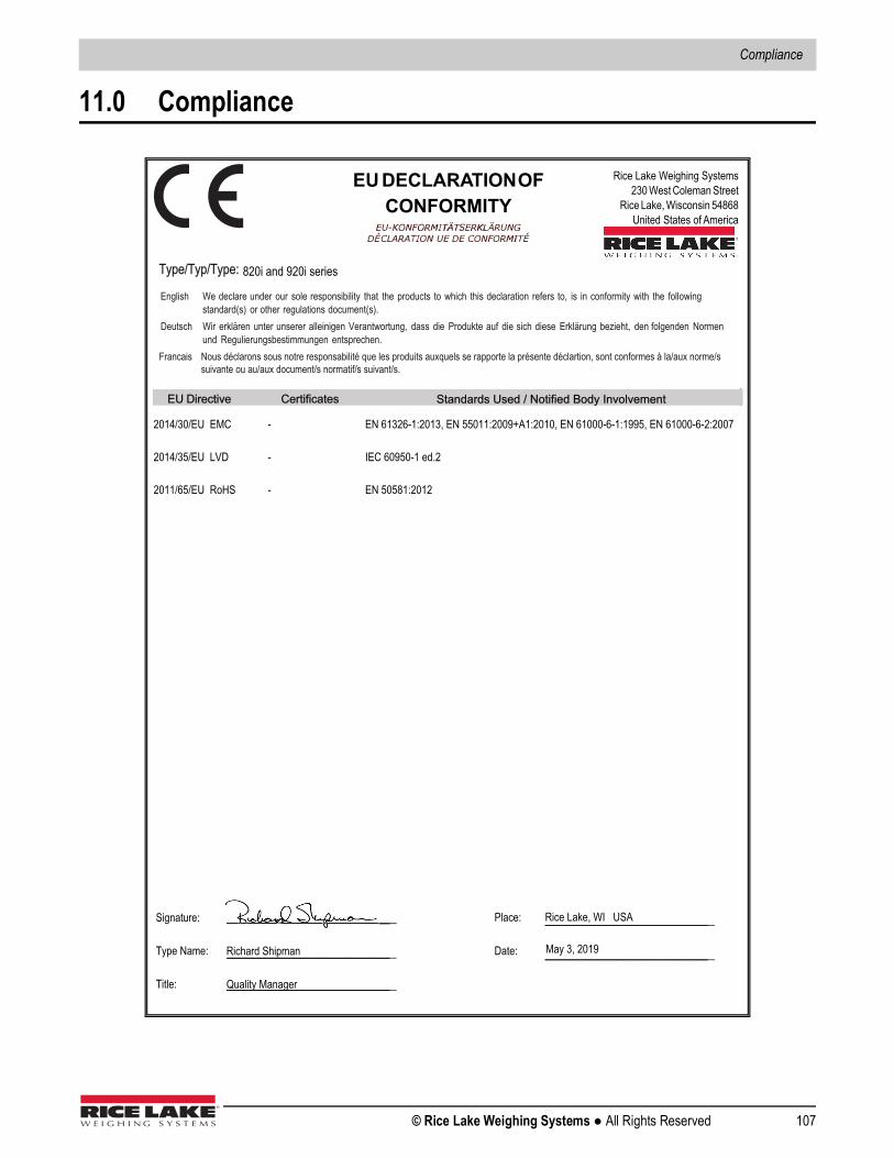
Compliance
© Rice Lake Weighing Systems ● All Rights Reserved 107
11.0 Compliance
__________________________
DECLARATIONOFCONFORMITY
__________________________
__________________________
____________________________________________________
__________________________________________________________________________________ _________________________________________________
820i and 920i series
2014/30/EU EMC
2014/35/EU LVD
2011/65/EU RoHS
- - -
EN 61326-1:2013, EN 55011:2009+A1:2010, EN 61000-6-1:1995, EN 61000-6-2:2007 IEC 60950-1 ed.2 EN 50581:2012
May 3, 2019
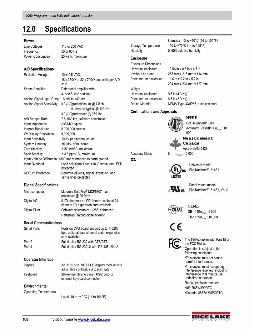
820i Programmable HMI Indicator/Controller
108 Visit our website www.RiceLake.com
12.0 SpecificationsPowerLine Voltages 115 or 230 VACFrequency 50 or 60 HzPower Consumption 25 watts maximum
A/D SpecificationsExcitation Voltage 10 ± 0.5 VDC,
16 x 350 or 32 x 700 load cells per A/D card
Sense Amplifier Differential amplifier with 4- and 6-wire sensing
Analog Signal Input Range –6 mV to +40 mVAnalog Signal Sensitivity 0.3 V/grad minimum @ 7.5 Hz
1.0 V/grad typical @ 120 Hz4.0 V/grad typical @ 960 Hz
A/D Sample Rate 7.5–960 Hz, software selectableInput Impedance >35 M typicalInternal Resolution 8 000 000 counts Wt Display Resolution 9,999,999Input Sensitivity 10 nV per internal countSystem Linearity ±0.01% of full scaleZero Stability ±150 nV/°C, maximumSpan Stability ± 3.5 ppm/°C, maximumInput Voltage Differential ±800 mV referenced to earth groundInput Overload Load cell signal lines ±10 V continuous, ESD
protectedRFI/EMI Protection Communications, signal, excitation, and
sense lines protected
Digital SpecificationsMicrocomputer Motorola ColdFire® MCF5307 main
processor @ 90 MHzDigital I/O 8 I/O channels on CPU board; optional 24-
channel I/O expansion card availableDigital Filter Software selectable: 1–256, enhanced
Rattletrap® hybrid digital filtering
Serial CommunicationsSerial Ports Ports on CPU board support up to 115200
bps; optional dual-channel serial expansion card available
Port 2 Full duplex RS-232 with CTS/RTSPort 4 Full duplex RS-232; 2-wire RS-485, 20mA
Operator InterfaceDisplay 320x156 pixel VGA LCD display module with
adjustable contrast, 75Hz scan rateKeyboard 28-key membrane panel, PS/2 port for
external keyboard connection
EnvironmentalOperating Temperature
Legal–10 to +40°C (14 to 104°F)
Industrial–10 to +40°C (14 to 104°F)Storage Temperature –10 to +70°C (14 to 158°F)Humidity 0–95% relative humidity
EnclosureEnclosure DimensionsUniversal enclosure 10.56 in x 8.5 in x 4.5 in (without tilt stand) 268 mm x 216 mm x 114 mmPanel mount enclosure 11.6 in x 9.2 in x 5.2 in
294 mm x 231 mm x 127 mmWeightUniversal enclosure 9.5 lb (4.3 Kg)Panel mount enclosure 8.5 lb (3.9 Kg)Rating/Material NEMA Type 4X/IP66, stainless steel
Certifications and ApprovalsNTEPCoC Number01-088Accuracy ClassIII/IIILnmax : 10 000
Measurement CanadaApprovalAM-5426
Accuracy Class III nmax : 10 000UL
Universal modelFile Number:E151461
Panel mount modelFile Number:E151461, Vol 2
OIMLGB-1140nmax : 6 000GB-1135nmax : 10 000
The 820i complies with Part 15 of the FCC Rules.Operation is subject to the following conditions:•This device may not cause harmful interference.•This device must accept any interference received, including interference that may cause undesired operation.Radio certificate number:•US: R68WIPORTG•Canada: 3867A-WIPORTG


230 W. Coleman St. • Rice Lake, WI 54868 • USAU.S. 800-472-6703 • Canada/Mexico 800-321-6703 • International 715-234-9171 • Europe +31 (0)26 472 1319
Rice Lake Weighing Systems is an ISO 9001 registered company. © Rice Lake Weighing Systems Specifications subject to change without notice.
www.ricelake.comMarch 26, PN 93018 Rev C


