Embed Size (px)
Citation preview
ITTC – Recommended
Procedures and Guidelines
7.5-04
-01-01.1
Page 1 of 23
Preparation and Conduct of
Speed/Power Trials
Effective Date
2014
Revision
04
Updated / Edited by Approved
Specialist Committee on Performance of
Ships in Service of the 27th ITTC
27th ITTC 2014
Date 03/2014 Date 09/2014
Table of Contents
1. PURPOSE .............................................. 3
2. DEFINITIONS ....................................... 3
3. RESPONSIBILITIES ............................ 4
3.1 Shipbuilders’ responsibilities ........... 4
3.2 The Trial Team .................................. 5
4. TRIAL PREPARATIONS .................... 5
4.1 Installation & Calibration ................ 5
4.2 S/P Trial Agenda and pre-trial
meeting ................................................ 7
5. SHIP CONDITION ............................... 7
5.1 Displacement ...................................... 7
5.2 Trim .................................................... 7
5.3 Hull & propeller ................................ 7
6. TRIAL BOUNDARY CONDITIONS .. 8
6.1 Location .............................................. 8
6.2 Wind .................................................... 8
6.3 Sea state .............................................. 8
6.4 Water depth ....................................... 9
6.5 Current ............................................... 9
7. TRIAL PROCEDURES ........................ 9
7.1 Parameters that shall be logged ....... 9
7.2 Primary parameters .......................... 9
7.3 Secondary parameters ..................... 10
7.4 General information ........................ 10
7.5 Model test information .................... 10
7.6 Scope and conduct of the
measurements .................................. 11
7.6.1 Ship track and Speed over Ground 11
7.6.2 Torque ........................................... 11
7.6.3 Wind .............................................. 11
7.6.4 Water depth ................................... 11
7.6.5 Waves ............................................ 11
7.6.6 Density and temperature ................ 12
7.6.7 Current ........................................... 12
8. TRIAL EXECUTION ......................... 12
8.1 Initiation ........................................... 12
8.2 Trial trajectory ................................ 12
8.3 Run duration & timing ................... 13
8.4 Trial direction .................................. 13
8.5 Steering ............................................. 13
8.6 Approach .......................................... 13
8.7 Number of speed runs ..................... 14
9. DATA ACQUISITION ....................... 15
9.1 General data ..................................... 15
9.2 Data on each run .............................. 15
9.3 Acquisition system ........................... 16
9.3.1 Minimum data ............................... 16
9.3.2 System requirements ..................... 16
9.3.3 Location ......................................... 16
9.4 Manual data collection .................... 16
10. REPORTING ....................................... 18

ITTC – Recommended
Procedures and Guidelines
7.5-04
-01-01.1
Page 2 of 23
Preparation and Conduct of
Speed/Power Trials
Effective Date
2014
Revision
04
11. REFERENCES .................................... 19
APPENDIX A: GENERAL SHIP AND
TRIAL DATA ...................................... 20
APPENDIX B: BEAUFORT SCALE OF
WIND .................................................... 21
APPENDIX C: FORMAT S/P TRIAL LOG
SHEET .................................................. 23
ITTC – Recommended
Procedures and Guidelines
7.5-04
-01-01.1
Page 3 of 23
Preparation and Conduct of
Speed/Power Trials
Effective Date
2014
Revision
04
Preparation and Conduct of Speed/Power Trials
1. PURPOSE
The primary purpose of speed-power trials is
to determine ship performance in terms of speed,
power and propeller revolutions under pre-
scribed ship conditions, and thereby verifying
the satisfactory attainment of the contractually
stipulated Ship Speed and to provide the Ship
Speed for the calculation of the Energy Effi-
ciency Design Index (EEDI) as required by IMO.
The present Recommended Procedure con-
cerns the preparation and execution of speed-
power trials and has been defined by the 27th
ITTC Specialist Committee on the Performance
of Ships in Service. In this work the Committee
took into account:
Recommendations 23rd ITTC 2002; Ref
[1],
ISO 19019, 2002; Ref [2],
ISO 15016, 2002; Ref [3],
STA-JIP, 2006; Ref [4],[8].
For the analysis and reporting of speed-
power trials, reference is made to Part 2 of this
Recommended Procedure. The purpose of this
document, Part 1, which is applicable to com-
mercial ships of displacement type, is to define
and specify:
the responsibility of each party involved,
the trial preparations,
the vessel’s condition,
the limiting weather and sea conditions,
the trial procedure,
the execution of the trial,
the measurements required,
the data acquisition and recording, and
the processing of the results.
The contracted ship speed and the speed for
EEDI shall be determined for stipulated condi-
tions which are defined at specific draughts
(contract draught and EEDI draught) and usu-
ally for ideal environmental conditions i.e. no
wind, no waves, no current, deep water.
Normally, such stipulated conditions are not
experienced during the actual trials. In practice,
certain corrections for the environmental condi-
tions, as for water depth, wind, waves and devi-
ating ship draught have to be considered. For
this purpose, not only the Shaft Power and Ship
Speed are measured, but also relevant ship data
and environmental conditions during the speed-
power trials.
In case it is physically impossible to meet the
conditions in these Guidelines, a practical ap-
proach mutually agreed by Owner, Verifier and
Shipbuilder can be allowed.
All trial procedures and measurements shall
be conducted in such a way that the speed at
Contract power and the speed at EEDI Power
are derived within 0.1 knots and the Shaft Power
within 2%.
2. DEFINITIONS
Brake Power: power delivered by the
output coupling of the propulsion machin-
ery.
Contract Power: Shaft Power that is stip-
ulated in the newbuilding or conversion
contract between Shipbuilder and Owner.
ITTC – Recommended
Procedures and Guidelines
7.5-04
-01-01.1
Page 4 of 23
Preparation and Conduct of
Speed/Power Trials
Effective Date
2014
Revision
04
Docking Report: report that documents
the condition of the ship hull and propul-
sors (available from the most recent dry-
docking).
Double Run: two consecutive Speed
Runs at the same power setting on recip-
rocal heading.
EEDI: Energy Efficiency Design Index as
formulated by IMO.
EEDI Power: Shaft Power that is stipu-
lated by the EEDI regulations.
Ideal Conditions: ideal weather and sea
condition; deep water, no wind, no waves
and no current.
Owner: party that signed the newbuilding
or conversion contract with the Ship-
builder.
Propeller Pitch: the design pitch, also for
controllable pitch propellers.
Running Pitch: the operating pitch of a
CPP.
Shaft Power: net power supplied by the
propulsion machinery to the propulsion
shafting after passing through all speed-
reducing and other transmission devices
and after power for all attached auxiliaries
has been taken off.
Shipbuilder: ship yard that signed the
newbuilding or conversion contract with
the Owner.
Ship Speed: speed that is realised under
the stipulated conditions. “Contract Speed”
refers to the contractual conditions agreed.
“EEDI Speed” refers to the conditions
specified by IMO. The ship’s speed during
a Speed Run is derived from the headway
distance between start and end position
and the elapsed time of the Speed Run.
Sister Ships: ships with identical main di-
mensions, body lines and propulsor sys-
tem built in a series by the same Ship-
builder.
S/P Trials: speed-power trials to establish
the Speed-Power relation of the vessel.
Speed Run: ship track with specified
heading, distance and duration over which
Ship Speed and Shaft Power are measured.
S/P Trial Agenda: document outlining
the scope of a particular S/P Trial. This
document contains the procedures on how
to conduct the trial and table(s) portraying
the runs to be conducted.
Trial Log: for each Speed Run, the log
contains the run number, the times when
the Speed Run starts and stops, and the
data as described in Section 9.4 and Ap-
pendix C of Part I of these Guidelines.
The Trial Leader is the duly authorised
(Shipbuilder’s representative) person re-
sponsible for the execution of all phases of
the S/P Trials including the pre-trial prep-
aration.
The Trial Team consists of the Trial
Leader, the Owner’s representative, the
appointed persons responsible for the S/P
Trial measurements and the Verifier.
Verifier: third party responsible for veri-
fication of the EEDI.
3. RESPONSIBILITIES
3.1 Shipbuilders’ responsibilities
The Shipbuilder is responsible for planning,
conducting and evaluating the S/P Trials:
Speed and Shaft Power measurements and
analysis shall be conducted by persons
acknowledged as competent to perform
those tasks, as agreed between the Ship-
builder, the Owner and the Verifier,
The Shipbuilder has to provide all permits
and certificates needed to go to sea,
The Shipbuilder is responsible for ensur-
ing that all qualified personnel, needed for
operating the ship, all engines, all systems
ITTC – Recommended
Procedures and Guidelines
7.5-04
-01-01.1
Page 5 of 23
Preparation and Conduct of
Speed/Power Trials
Effective Date
2014
Revision
04
and equipment during the sea trials are on
board,
The Shipbuilder is responsible for ensur-
ing that all regulatory bodies, Classifica-
tion Society, Owner, ship agents, suppli-
ers, subcontractors, harbour facilities, de-
partments organising the delivery of pro-
visions, fuel, water, towing, etc., needed
for conducting the sea trials, have been in-
formed and are available and on board,
when required,
It is the Shipbuilder’s responsibility that
all safety measures have been checked and
that all fixed, portable and individual ma-
terial (for crew, trial personnel and guests)
is on board and operative,
It is the Shipbuilder’s responsibility that
dock trials of all systems have been exe-
cuted and all alarms, warning and safety
systems have been checked,
It is the Shipbuilder’s responsibility that
an inclining test has been performed
and/or at least a preliminary stability
booklet including S/P Trials condition has
been approved, in accordance with the
SOLAS Convention,
It is the Shipbuilders responsibility that all
ship data relevant for the S/P Trials Prep-
aration, Conduct, Analysis and Reporting
are made available to the Trial Team prior
to the S/P Trials. This data shall include
the information requested in Appendix A
as well as the results of the model tests for
this ship at trial draught and trim, EEDI
draught and trim and Contract draught and
trim.
The Shipbuilder is responsible for the over-
all trial coordination between the ship's crew
and Trial Team. A pre-trial meeting between the
Trial Team and the ship’s crew shall be held to
discuss the various trial events and to resolve
any outstanding issues.
The Shipbuilder has to arrange for divers to
inspect the ship’s hull and propulsor if necessary.
The Trial Leader maintains contact with the
Trial Team on the preparation, execution and re-
sults of the S/P Trials.
3.2 The Trial Team
The Trial Team is responsible for correct
measurements and reporting of the S/P Trials
according to this document and for the analysis
of the measured data to derive the ship’s speed
and power at the stipulated conditions. This
analysis shall be conducted in compliance with
Part 2 of this Recommended Procedure.
The Trial Team is responsible for the follow-
ing:
conducting inspection of ship including
hull and propeller condition,
providing, installing and operating all re-
quired trial instrumentation and temporary
cabling,
providing the ship master and Owner’s
representative with a preliminary data
package and preliminary analysis before
debarking,
providing a final report after completion
of the trials in accordance with Chapter 10.
4. TRIAL PREPARATIONS
The success of the S/P Trials largely depends
on the preparations. In this chapter, the most im-
portant steps are summarised.
4.1 Installation & Calibration
Assemble all trials instrumentation in the
configuration that will be used on the ship. Test
the instrumentation system on malfunctioning
or any other complications.

ITTC – Recommended
Procedures and Guidelines
7.5-04
-01-01.1
Page 6 of 23
Preparation and Conduct of
Speed/Power Trials
Effective Date
2014
Revision
04
Apart from the obvious signals such as shaft
torque, rpm and DGPS, it is important to check:
1. Gyrocompasses
2. Anemometer system
3. Speed log system
4. Propeller Pitch (of each propeller)
5. Ship’s draught measurement system (if
available)
6. Water depth measuring system
All shipboard signals that will be recorded
during the S/P Trials shall be calibrated after the
instrumentation is installed prior to the S/P Tri-
als. For this purpose, the sensors shall be cycled
throughout the full operating range of the sys-
tem.
This is accomplished by:
Slewing the gyrocompasses
Changing the Propeller Pitch
Prior to departure on S/P Trials, the ship’s
draught measurement system (if available)
needs to be verified by directly reading all
draught marks, seawater temperature, specific
density and the internal draught system at the
same time.
The Shaft Power will be derived from torque
and rpm.
Shaft torque shall be measured by means of
permanent torque sensor or strain gauges on the
shaft. The measurement system shall be certi-
fied for power measurements on a test shaft with
a bias error smaller than 1% so that an overall
bias error smaller than 2% (on board of the ac-
tual ship) can be achieved.
Alternative shaft torque measurement de-
vices with a certified accuracy equal to or better
than the above figures are acceptable.
As part of the S/P Trial preparation, the tor-
sion meter’s zero torque readings shall be deter-
mined since there is a residual torque in the shaft,
which is resting on the line shaft bearings. The
torsion meter zero setting is to be done accord-
ing to its maker’s instructions.
The shaft material properties, i.e. the G-
Modulus, as specified and documented by the
shaft supplier shall be provided by the Ship-
builder. The shaft diameter used in the power
calculation shall be derived from the shaft cir-
cumference in-situ measured at the location of
the torque measurement. In case of variable
pitch propeller there might be a drilling diameter
to be taken into account (to be supplied by Ship-
builder).
In case shaft torque measurement is not pos-
sible, an alternative power measurement method
recommended by the engine manufacturer and
approved by Owner and Verifier is acceptable.
As part of the pre-trial calibration for a ship
equipped with controllable pitch propellers, the
procedure shall be as follows:
1. Prior to dock-out the oil distribution
mechanism showing the Propeller Pitch
shall be checked for zero pitch;
2. Check zero pitch reading in the measure-
ment system against the mechanical
reading in the oil distribution box;
3. Determine the maximum ahead pitch,
design pitch, and maximum astern pitch
and then adjust the ship indicators to re-
flect the measurement. Determine the
corrections to account for changes in
pitch due to shaft compression as thrust
increases and temperature effects on the
Propeller Pitch control rod.
4. Verify the weight of the propulsor and
hub from the manufacturer’s specifica-
tions for making thrust measurement
corrections.
ITTC – Recommended
Procedures and Guidelines
7.5-04
-01-01.1
Page 7 of 23
Preparation and Conduct of
Speed/Power Trials
Effective Date
2014
Revision
04
An important deliverable of this stage will be
a document describing the test set-up, and the
calibrations including evidence of the calibra-
tions that have been carried out.
It is important to note that there are two
stages to consider in performing instrumentation
checks, viz. the pre-trial check procedures and
the post-trial check to verify the calibration re-
sults.
4.2 S/P Trial Agenda and pre-trial meet-
ing
Before departure, a pre-trial meeting shall be
held to fix the S/P Trial Agenda. During this
meeting two items shall be addressed.
Approval of the S/P Trial Agenda;
Approval of the procedures that will be
used to calculate the trial speed and to de-
liver the speed trial report i.e. Part 2 of this
Recommended Procedure.
The S/P Trial Agenda is a document pre-
pared by the Shipbuilder, outlining amongst oth-
ers the scope of a particular Speed/Power trial.
This document contains the procedures on how
to conduct the trial and table(s) portraying the
runs to be conducted. It outlines the particular
responsibilities of the Trial Leader, Trial Team,
ship’s crew/ Shipbuilder, and the Owner’s rep-
resentative. The scope of the S/P Trials shall be
in line with this document.
5. SHIP CONDITION
5.1 Displacement
The ship’s displacement shall be within 2%
difference of the actual required displacement.
If model test results are used for the analysis of
the S/P Trials, the displacement used in the
model tests shall be within 2% of the displace-
ment during the S/P Trials.
Draught at the perpendiculars, trim and dis-
placement of the S/P Trials are obtained by av-
eraging the ship draught mark readings. The
ship shall be brought into a loading condition
that is as close as possible to contract condition
and/or the condition at which model tests have
been carried out.
The loading condition shall be confirmed at
zero Ship Speed. Draught at the perpendiculars,
trim and displacement shall be obtained at the
beginning of the trial.
Displacement shall be derived from the
Bonjean data or using quadratic equations with
hydrostatic data, taking into consideration the
hog/sag using the draught data (forward, aft and
at half length) and the density of the water.
5.2 Trim
The trim shall be maintained within very
narrow limits. For the even keel condition the
trim shall be less than 1.0% of the mid-ships
draught. For trimmed trial conditions, the im-
mergence of the bulbous bow shall be within ±
0.1 m read at the forward draught marks, of the
ship condition for which model test results are
available.
In case draught and trim requirements can-
not be met at the same time, the above immer-
gence requirement of the bulbous bow super-
sedes.
5.3 Hull & propeller
The ship shall have clean hull and propeller
for the sea trial. Hull roughness and marine
growth can increase the resistance of the ship
significantly but are not corrected for in S/P Tri-
als. Therefore, it is recommended that the hull
ITTC – Recommended
Procedures and Guidelines
7.5-04
-01-01.1
Page 8 of 23
Preparation and Conduct of
Speed/Power Trials
Effective Date
2014
Revision
04
and propeller(s) are cleaned just prior to the sea
trials. The date of last docking and hull and pro-
peller cleaning are to be documented in the S/P
Trials report.
6. TRIAL BOUNDARY CONDITIONS
During the S/P Trial, there are many condi-
tions that deviate from the contract condition.
The objective during the S/P Trial is to keep the
number of influencing factors as limited as pos-
sible.
Although there are correction methods for
certain deviations from the contract condition,
these methods are only valid up to certain limits.
In order to arrive at reliable S/P Trial results
the boundary conditions shall not exceed the
values given in this chapter.
6.1 Location
High wind and sea state in combination with
a heading deviating from head waves and fol-
lowing waves, can force the use of excessive
rudder deflections to maintain heading, and thus
cause excessive fluctuations in shaft torque,
shaft speed and Ship Speed.
The S/P Trial shall be conducted in a loca-
tion where the environmental conditions are
constant and have only the smallest possible im-
pact on the vessel in order to avoid unexpected
environmental effects in the S/P Trial results.
This means that the speed trial range shall be
located in a sheltered area (i.e. limited wind,
waves and current). Furthermore, the area shall
be free from hindering small boats and commer-
cial traffic.
1 The Beaufort scale is given in Appendix B
6.2 Wind
During the S/P Trial the wind speeds shall
not be higher than:
Beaufort number 6 1 , for vessels with
LPP >100 m, or
Beaufort number 5, for vessel with LPP
≤100 m
where :
LPP : Length between perpendiculars [m].
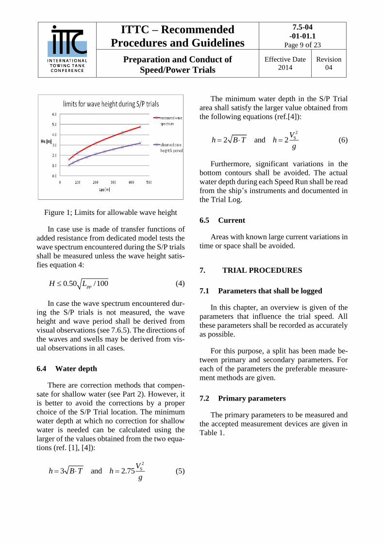
6.3 Sea state
The total wave height H, derived from the
significant wave heights of local wind driven
seas 1/3WH and swells 1/3SH , by
2 2
1/3 1/3W SH H H (1)
shall satisfy the following criteria:
In case the wave spectrum encountered dur-
ing the S/P trials is measured:
2.25 /100ppLH (2)
In case the wave height is derived from vis-
ual observations:
1.50 /100ppLH (3)
where:
LPP: Length between perpendiculars [m]
The above limits are illustrated in Figure 1.
ITTC – Recommended
Procedures and Guidelines
7.5-04
-01-01.1
Page 9 of 23
Preparation and Conduct of
Speed/Power Trials
Effective Date
2014
Revision
04
Figure 1; Limits for allowable wave height
In case use is made of transfer functions of
added resistance from dedicated model tests the
wave spectrum encountered during the S/P trials
shall be measured unless the wave height satis-
fies equation 4:
0.50 /100ppLH (4)
In case the wave spectrum encountered dur-
ing the S/P trials is not measured, the wave
height and wave period shall be derived from
visual observations (see 7.6.5). The directions of
the waves and swells may be derived from vis-
ual observations in all cases.
6.4 Water depth
There are correction methods that compen-
sate for shallow water (see Part 2). However, it
is better to avoid the corrections by a proper
choice of the S/P Trial location. The minimum
water depth at which no correction for shallow
water is needed can be calculated using the
larger of the values obtained from the two equa-
tions (ref. [1], [4]):
2
S3 and 2.75V
h B T hg
(5)
The minimum water depth in the S/P Trial
area shall satisfy the larger value obtained from
the following equations (ref.[4]):
2
S2 and 2V
h B T hg
(6)
Furthermore, significant variations in the
bottom contours shall be avoided. The actual
water depth during each Speed Run shall be read
from the ship’s instruments and documented in
the Trial Log.
6.5 Current
Areas with known large current variations in
time or space shall be avoided.
7. TRIAL PROCEDURES
7.1 Parameters that shall be logged
In this chapter, an overview is given of the
parameters that influence the trial speed. All
these parameters shall be recorded as accurately
as possible.
For this purpose, a split has been made be-
tween primary and secondary parameters. For
each of the parameters the preferable measure-
ment methods are given.
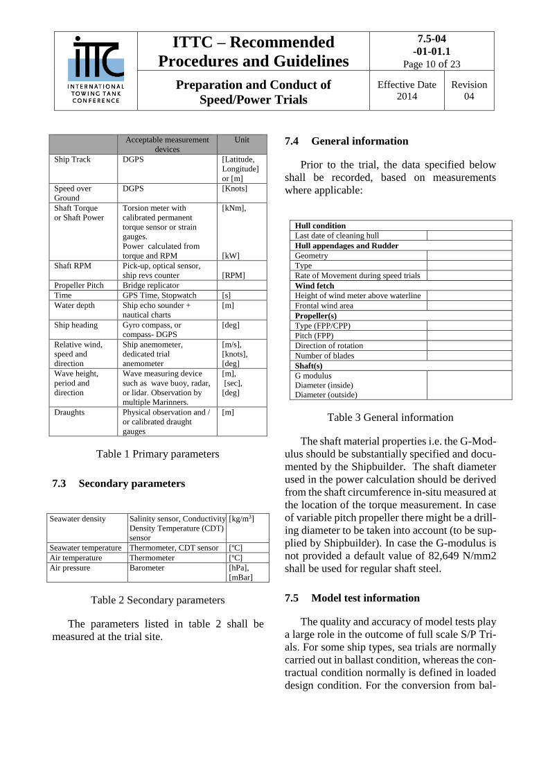
7.2 Primary parameters
The primary parameters to be measured and
the accepted measurement devices are given in
Table 1.
ITTC – Recommended
Procedures and Guidelines
7.5-04
-01-01.1
Page 10 of 23
Preparation and Conduct of
Speed/Power Trials
Effective Date
2014
Revision
04
Acceptable measurement
devices
Unit
Ship Track DGPS [Latitude,
Longitude]
or [m]
Speed over
Ground
DGPS
[Knots]
Shaft Torque
or Shaft Power
Torsion meter with
calibrated permanent
torque sensor or strain
gauges.
Power calculated from
torque and RPM
[kNm],
[kW]
Shaft RPM Pick-up, optical sensor,
ship revs counter
[RPM]
Propeller Pitch Bridge replicator
Time GPS Time, Stopwatch [s]
Water depth Ship echo sounder +
nautical charts
[m]
Ship heading Gyro compass, or
compass- DGPS
[deg]
Relative wind,
speed and
direction
Ship anemometer,
dedicated trial
anemometer
[m/s],
[knots],
[deg]
Wave height,
period and
direction
Wave measuring device
such as wave buoy, radar,
or lidar. Observation by
multiple Marinners.
[m],
[sec],
[deg]
Draughts Physical observation and /
or calibrated draught
gauges
[m]
Table 1 Primary parameters
7.3 Secondary parameters
Seawater density Salinity sensor, Conductivity
Density Temperature (CDT)
sensor
[kg/m3]
Seawater temperature Thermometer, CDT sensor [ºC]
Air temperature Thermometer [ºC]
Air pressure Barometer [hPa],
[mBar]
Table 2 Secondary parameters
The parameters listed in table 2 shall be
measured at the trial site.
7.4 General information
Prior to the trial, the data specified below
shall be recorded, based on measurements
where applicable:
Hull condition
Last date of cleaning hull
Hull appendages and Rudder
Geometry
Type
Rate of Movement during speed trials
Wind fetch
Height of wind meter above waterline
Frontal wind area
Propeller(s)
Type (FPP/CPP)
Pitch (FPP)
Direction of rotation
Number of blades
Shaft(s)
G modulus
Diameter (inside)
Diameter (outside)
Table 3 General information
The shaft material properties i.e. the G-Mod-
ulus should be substantially specified and docu-
mented by the Shipbuilder. The shaft diameter
used in the power calculation should be derived
from the shaft circumference in-situ measured at
the location of the torque measurement. In case
of variable pitch propeller there might be a drill-
ing diameter to be taken into account (to be sup-
plied by Shipbuilder). In case the G-modulus is
not provided a default value of 82,649 N/mm2
shall be used for regular shaft steel.
7.5 Model test information
The quality and accuracy of model tests play
a large role in the outcome of full scale S/P Tri-
als. For some ship types, sea trials are normally
carried out in ballast condition, whereas the con-
tractual condition normally is defined in loaded
design condition. For the conversion from bal-

ITTC – Recommended
Procedures and Guidelines
7.5-04
-01-01.1
Page 11 of 23
Preparation and Conduct of
Speed/Power Trials
Effective Date
2014
Revision
04
last trial results to loaded condition, the differ-
ence between the ballast and loaded model test
curves is used. Therefore, an accurate model test
and validated consistent extrapolation method to
full scale is required.
For the analysis of the S/P Trials, i.e. to in-
clude the effect of the propeller loading in non-
ideal conditions on the propulsion efficiency
and rpm, it is required that the model tests data
include the results of propeller load variation
measurements as defined in Part 2.
Based on ITTC recommendations, the model
tests shall be conducted according to the follow-
ing criteria:
Model tests shall be conducted at the con-
tract draught & trim, the EEDI draught & trim
as well as the trial draught & trim.
Model tests shall be conducted according to
the ITTC Recommended Procedures for Re-
sistance and Propulsion Model Tests, including
load variation tests. Ref [5].
For all draughts and trims, the same methods,
procedures and empirical coefficients shall be
used to extrapolate the model scale values to full
scale. In case different methods, procedures or
empirical coefficients are used for the different
draughts, these shall be documented in full de-
tail and documentation must include justifica-
tion by means of full scale S/P Trial data for the
specific ship type, size, loading condition,
model test facility and evaluation method.
The model test report shall be transparent
and give sufficient information to enable the
EEDI Verifier to check the model test results.
This means that in the model test report, the
measured data, the predicted full scale data and
a detailed description of the extrapolation
method and the coefficients used have to be
given.
7.6 Scope and conduct of the measure-
ments
7.6.1 Ship track and Speed over Ground
The speed is to be measured by a global po-
sitioning system such as GPS. The GPS system
shall operate in the Differential mode to ensure
sufficient accuracy. The position and speed shall
be monitored and stored continuously.
7.6.2 Torque
The calibration of the torque measurement
shall not be altered during the S/P Trials.
7.6.3 Wind
The ship’s own sensor or a dedicated trial an-
emometer can be used. The anemometer shall be
as clear as possible from the superstructure.
7.6.4 Water depth
Measuring the water depth can be done by
using the ship echo sounder. It is important that
the echo sounder is calibrated before the Speed
Run in combination with the check of the water
depth given on the charts and that the vessel
draught is taken into account. Continuous re-
cording of water depth is recommended.
7.6.5 Waves
Preferably, the wave height, wave period
and direction of waves induced by local wind
and swell originating from remote wind, shall be
measured during the S/P Trials. For this purpose,
use can be made of wave buoys in the speed trial
area or from ship born equipment such as wave
radar or lidar. The wave measurement equip-
ment shall be calibrated and the accuracy shall
be validated and documented.
ITTC – Recommended
Procedures and Guidelines
7.5-04
-01-01.1
Page 12 of 23
Preparation and Conduct of
Speed/Power Trials
Effective Date
2014
Revision
04
If for the wave correction use is made of
transfer functions of added resistance in waves
derived from model tests for the subject ship, the
wave spectrum encountered during the Speed
Runs shall be measured unless the wave height
satisfies: H ≤ 0.50 /100ppL (see 6.3). Use can
be made of wave buoys or instruments on-board
the ship such as wave radar and wave scanner.
If use is made of the empirical wave correc-
tion methods described in Part 2 (without spe-
cific model tests) and provided that Double
Runs are conducted in head and following seas,
and if the wave heights satisfies: H ≤ 1.50
/100ppL ) (see 6.3), the encountered wave
heights, periods and directions of both seas and
swells may be determined from observations by
multiple experienced Mariners, including the
Owner’s representative and the Verifier. In ad-
dition to the wave observations, wave hind cast
data provided by an experienced and independ-
ent weather office may be used.
7.6.6 Density and temperature
The local seawater temperature and density
at the trial site need to be recorded to enable the
calculation of the ship’s displacement and cor-
rections with regard to viscosity. The water tem-
perature shall be taken at sea water inlet level.
Air temperature and pressure shall be measured
at the trial location using a calibrated thermom-
eter and barometer.
7.6.7 Current
Speed and direction of current shall be de-
rived as part of the evaluation of each run. For
each Speed Run in a set of Double Run(s), this
current follows from the “mean of means” value
derived from all Speed Runs at the same power
setting and the measured value for the specific
Speed Run after corrections. (See Section 10).
8. TRIAL EXECUTION
On the day of and during the S/P Trial, a
number of prerequisites shall be met in order to
arrive at reliable trial results. In this chapter, an
overview is given of the minimum requirements.
8.1 Initiation
Prior to the S/P Trials, the weather forecast
shall be studied.
In case wave height, period or wave direc-
tion are derived from visual observation, the
schedule for the S/P Trials shall be arranged
such that all Speed Runs around EEDI Power
are conducted by daylight.
It is important to check that the engine plant
line up during the S/P Trial is consistent with
normal ship operations.
Before the actual start of the S/P Trials, the
following actions shall be taken when the vessel
is stopped in the water (within the schedule of
the trials):
1. draught reading as described in section
5.1 and calculation of displacement,
2. measurement of wind speed and direc-
tion,
3. zero setting of shaft torque meter,
4. measurement of water temperature and
density.
8.2 Trial trajectory
The S/P Trial Runs need to be conducted
over the same ground area. For each base course,
each Trial Run will be commenced (COMEX)
at the same place (within reason).
ITTC – Recommended
Procedures and Guidelines
7.5-04
-01-01.1
Page 13 of 23
Preparation and Conduct of
Speed/Power Trials
Effective Date
2014
Revision
04
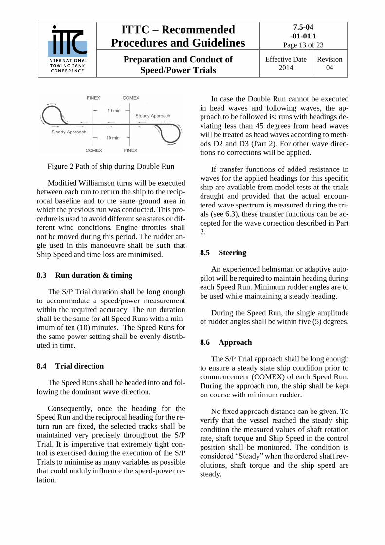
Figure 2 Path of ship during Double Run
Modified Williamson turns will be executed
between each run to return the ship to the recip-
rocal baseline and to the same ground area in
which the previous run was conducted. This pro-
cedure is used to avoid different sea states or dif-
ferent wind conditions. Engine throttles shall
not be moved during this period. The rudder an-
gle used in this manoeuvre shall be such that
Ship Speed and time loss are minimised.
8.3 Run duration & timing
The S/P Trial duration shall be long enough
to accommodate a speed/power measurement
within the required accuracy. The run duration
shall be the same for all Speed Runs with a min-
imum of ten (10) minutes. The Speed Runs for
the same power setting shall be evenly distrib-
uted in time.
8.4 Trial direction
The Speed Runs shall be headed into and fol-
lowing the dominant wave direction.
Consequently, once the heading for the
Speed Run and the reciprocal heading for the re-
turn run are fixed, the selected tracks shall be
maintained very precisely throughout the S/P
Trial. It is imperative that extremely tight con-
trol is exercised during the execution of the S/P
Trials to minimise as many variables as possible
that could unduly influence the speed-power re-
lation.
In case the Double Run cannot be executed
in head waves and following waves, the ap-
proach to be followed is: runs with headings de-
viating less than 45 degrees from head waves
will be treated as head waves according to meth-
ods D2 and D3 (Part 2). For other wave direc-
tions no corrections will be applied.
If transfer functions of added resistance in
waves for the applied headings for this specific
ship are available from model tests at the trials
draught and provided that the actual encoun-
tered wave spectrum is measured during the tri-
als (see 6.3), these transfer functions can be ac-
cepted for the wave correction described in Part
2.
8.5 Steering
An experienced helmsman or adaptive auto-
pilot will be required to maintain heading during
each Speed Run. Minimum rudder angles are to
be used while maintaining a steady heading.
During the Speed Run, the single amplitude
of rudder angles shall be within five (5) degrees.
8.6 Approach
The S/P Trial approach shall be long enough
to ensure a steady state ship condition prior to
commencement (COMEX) of each Speed Run.
During the approach run, the ship shall be kept
on course with minimum rudder.
No fixed approach distance can be given. To
verify that the vessel reached the steady ship
condition the measured values of shaft rotation
rate, shaft torque and Ship Speed in the control
position shall be monitored. The condition is
considered “Steady” when the ordered shaft rev-
olutions, shaft torque and the ship speed are
steady.
ITTC – Recommended
Procedures and Guidelines
7.5-04
-01-01.1
Page 14 of 23
Preparation and Conduct of
Speed/Power Trials
Effective Date
2014
Revision
04
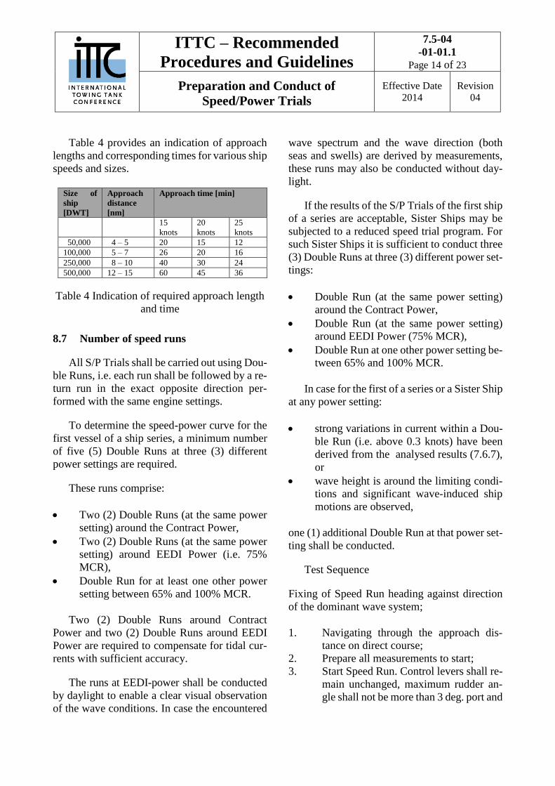
Table 4 provides an indication of approach
lengths and corresponding times for various ship
speeds and sizes.
Size of
ship
[DWT]
Approach
distance
[nm]
Approach time [min]
15
knots
20
knots
25
knots
50,000 4 – 5 20 15 12
100,000 5 – 7 26 20 16
250,000 8 – 10 40 30 24
500,000 12 – 15 60 45 36
Table 4 Indication of required approach length
and time
8.7 Number of speed runs
All S/P Trials shall be carried out using Dou-
ble Runs, i.e. each run shall be followed by a re-
turn run in the exact opposite direction per-
formed with the same engine settings.
To determine the speed-power curve for the
first vessel of a ship series, a minimum number
of five (5) Double Runs at three (3) different
power settings are required.
These runs comprise:
Two (2) Double Runs (at the same power
setting) around the Contract Power,
Two (2) Double Runs (at the same power
setting) around EEDI Power (i.e. 75%
MCR),
Double Run for at least one other power
setting between 65% and 100% MCR.
Two (2) Double Runs around Contract
Power and two (2) Double Runs around EEDI
Power are required to compensate for tidal cur-
rents with sufficient accuracy.
The runs at EEDI-power shall be conducted
by daylight to enable a clear visual observation
of the wave conditions. In case the encountered
wave spectrum and the wave direction (both
seas and swells) are derived by measurements,
these runs may also be conducted without day-
light.
If the results of the S/P Trials of the first ship
of a series are acceptable, Sister Ships may be
subjected to a reduced speed trial program. For
such Sister Ships it is sufficient to conduct three
(3) Double Runs at three (3) different power set-
tings:
Double Run (at the same power setting)
around the Contract Power,
Double Run (at the same power setting)
around EEDI Power (75% MCR),
Double Run at one other power setting be-
tween 65% and 100% MCR.
In case for the first of a series or a Sister Ship
at any power setting:
strong variations in current within a Dou-
ble Run (i.e. above 0.3 knots) have been
derived from the analysed results (7.6.7),
or
wave height is around the limiting condi-
tions and significant wave-induced ship
motions are observed,
one (1) additional Double Run at that power set-
ting shall be conducted.
Test Sequence
Fixing of Speed Run heading against direction
of the dominant wave system;
1. Navigating through the approach dis-
tance on direct course;
2. Prepare all measurements to start;
3. Start Speed Run. Control levers shall re-
main unchanged, maximum rudder an-
gle shall not be more than 3 deg. port and
ITTC – Recommended
Procedures and Guidelines
7.5-04
-01-01.1
Page 15 of 23
Preparation and Conduct of
Speed/Power Trials
Effective Date
2014
Revision
04
starboard. After agreed duration (mini-
mum of 10 minutes) stop Speed Run.
Determine the achieved speed and
power;
4. During S/P Trial Run make environmen-
tal observations;
5. Turn ship with small rudder angles to
navigate the counter run covering the
same geographical track as the first run;
6. Repeat steps 2 to 6.
9. DATA ACQUISITION
During the speed/power trial, accurate re-
cording of the speed and power relationship is
of great importance.
Apart from this, an accurate quantification of
the boundary conditions is necessary since the
ship’s speed and powering characteristics are
extremely sensitive to conditions such as ship
and propeller condition, ship displacement,
shallow water effects, sea state and wind veloc-
ity. Consequently, these factors shall be moni-
tored and documented to the greatest possible
extent.
During the S/P Trials, two types of data ac-
quisition shall be used: Automated acquisition
by means of a data acquisition system (measure-
ment computer), and information that is noted
down by means of a log sheet. The objective
shall always be to record as many parameters as
possible by means of the measurement computer
in order to increase the level of accuracy of the
S/P Trials.
In general, data to be acquired can be divided
into general data which is applicable to all Speed
Runs and specific data that is varying through-
out every run.
9.1 General data
Prior to the trial, the data specified below
shall be recorded, based on measurements
where relevant:
Date
Area of trial (in Latitude/Longitude co-or-
dinates)
Weather
Water temperature and density
Air temperature
Height of anemometer above waterline
Fore, amidships and aft draughts
Displacement
In order to verify the wind data measured
during the S/P Trials, it is recommended to rec-
ord the absolute wind speed and direction at
shore based station(s) or as measured directly
prior to and after finalising the speed trials while
the vessel is stopped.
9.2 Data on each run
Clock time at commencement (UTC)
Start and end position in Latitude/Longi-
tude coordinates
Time elapsed over the measured distance
Ship’s heading
Ship’s speed over ground
Ship’s course over ground
Propeller rate of revolutions
Propeller shaft torque and/or power
Propeller Pitch in case of CPP
Relative wind velocity and direction by
anemometer
Mean wave period, significant wave
height and direction of wind driven seas
Mean wave period, significant wave
height and direction of swell waves
Mean water depth.
ITTC – Recommended
Procedures and Guidelines
7.5-04
-01-01.1
Page 16 of 23
Preparation and Conduct of
Speed/Power Trials
Effective Date
2014
Revision
04
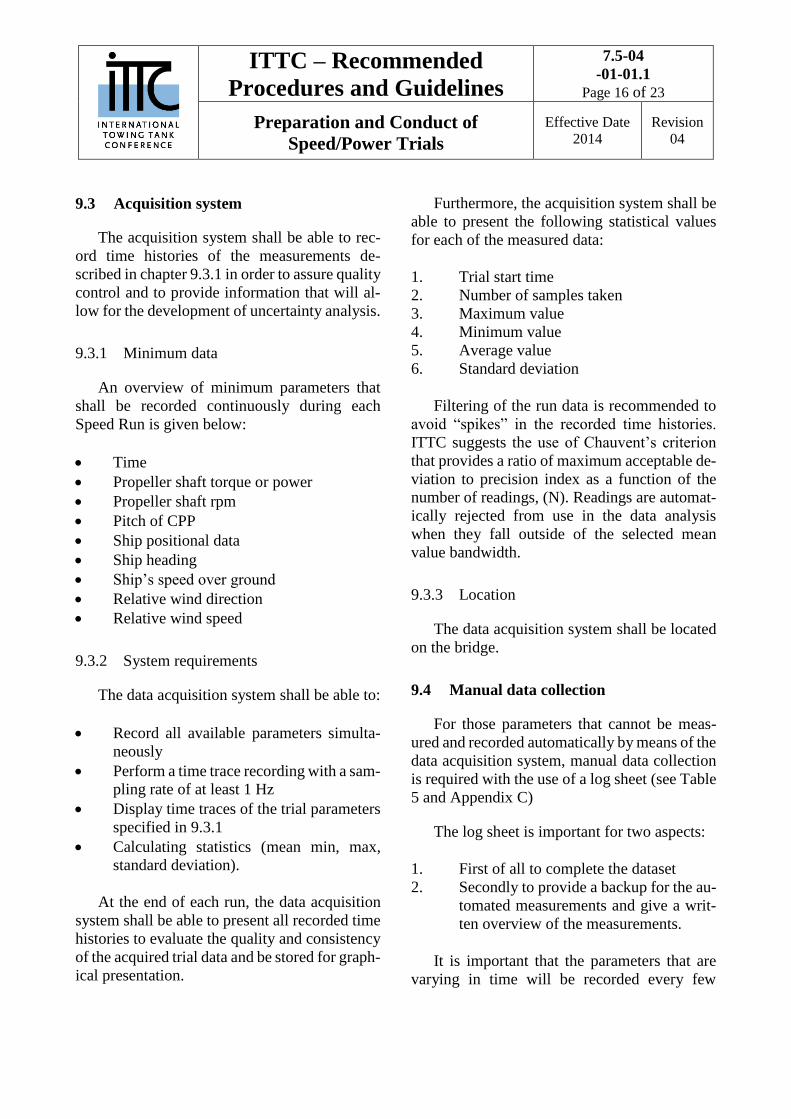
9.3 Acquisition system
The acquisition system shall be able to rec-
ord time histories of the measurements de-
scribed in chapter 9.3.1 in order to assure quality
control and to provide information that will al-
low for the development of uncertainty analysis.
9.3.1 Minimum data
An overview of minimum parameters that
shall be recorded continuously during each
Speed Run is given below:
Time
Propeller shaft torque or power
Propeller shaft rpm
Pitch of CPP
Ship positional data
Ship heading
Ship’s speed over ground
Relative wind direction
Relative wind speed
9.3.2 System requirements
The data acquisition system shall be able to:
Record all available parameters simulta-
neously
Perform a time trace recording with a sam-
pling rate of at least 1 Hz
Display time traces of the trial parameters
specified in 9.3.1
Calculating statistics (mean min, max,
standard deviation).
At the end of each run, the data acquisition
system shall be able to present all recorded time
histories to evaluate the quality and consistency
of the acquired trial data and be stored for graph-
ical presentation.
Furthermore, the acquisition system shall be
able to present the following statistical values
for each of the measured data:
1. Trial start time
2. Number of samples taken
3. Maximum value
4. Minimum value
5. Average value
6. Standard deviation
Filtering of the run data is recommended to
avoid “spikes” in the recorded time histories.
ITTC suggests the use of Chauvent’s criterion
that provides a ratio of maximum acceptable de-
viation to precision index as a function of the
number of readings, (N). Readings are automat-
ically rejected from use in the data analysis
when they fall outside of the selected mean
value bandwidth.
9.3.3 Location
The data acquisition system shall be located
on the bridge.
9.4 Manual data collection
For those parameters that cannot be meas-
ured and recorded automatically by means of the
data acquisition system, manual data collection
is required with the use of a log sheet (see Table
5 and Appendix C)
The log sheet is important for two aspects:
1. First of all to complete the dataset
2. Secondly to provide a backup for the au-
tomated measurements and give a writ-
ten overview of the measurements.
It is important that the parameters that are
varying in time will be recorded every few

ITTC – Recommended
Procedures and Guidelines
7.5-04
-01-01.1
Page 17 of 23
Preparation and Conduct of
Speed/Power Trials
Effective Date
2014
Revision
04
minutes so that the average can be determined
over the run period.
An example of a log sheet that can be used
is shown in Table 5 and given in further detail in
Appendix C. The sign conventions to be used
for wave and wind direction are presented in
Figures 3, 4 and 5.
Table 5 Example of a log form
Figure 3 Sign conventions
Figure 4 Sign convention for wind directions
The wind direction is defined as the direction
where the wind is coming from. Zero (0) degrees
on the bow and positive to starboard (clockwise).
Input parameters:
Heading: Heading of the ship [deg]
VWR: Relative wind speed [knots]
ψWR: Relative wind direction relative to the
bow, ship fixed; 0 means heading winds [deg]
VG: Ship Speed over ground [knots]
Computed parameters:
ΒWT: True wind angle in earth system [deg]
VWT: True wind speed [knots]
Ship name: Date:
Ship
m Tair ⁰ C outer dia D1 mm
m Twater ⁰ C inner dia D2 mm
Displacement tons ρwater kg/m3 steel type N/mm2
m
Run No. TimeForward
/ Return
run
HeadingSpeed
(SOG)UKC Speed Direction Height Direction Period Height Direction Period Torque Power Revs Torque Power Revs
[-] [-] [F / R] [deg] [kn] [m] [kn] [m/s] [deg] [m] [deg] [s ] [m] [deg] [s ] [kNm] [kW] [RPM] [kNm] [kW] [RPM]
Speed - Power Trials Log Form
Propeller shaft Measurement location:
Lat
Lon
Description
Height of anemometer above water line:
Tfwd
Taft
Environment
Relative wind Wind driven waves Swel l Propel ler SBPropel ler PS

ITTC – Recommended
Procedures and Guidelines
7.5-04
-01-01.1
Page 18 of 23
Preparation and Conduct of
Speed/Power Trials
Effective Date
2014
Revision
04
Figure 5 Sign convention for wave directions
The wave direction is defined as the direc-
tion where the waves are coming from.
Zero (0) degrees on the bow and positive to star-
board (clockwise).
Input parameters:
Heading: Heading of the ship [deg]
H1/3: Significant wave height (wind driven or
swell) [m],
α: Angle between ship heading and wave
direction relative to the bow; 0 means head
waves [deg]
VG: Ship Speed over ground [knots]
10. REPORTING
In the trial report, an overview is given of the
trial conditions and all corrections that have
been applied to arrive at the Contract Speed and
the EEDI Speed.
The trial report shall contain all relevant in-
formation to carry out the data analysis. It shall
be written in such a way that all results can be
reprocessed.
The trial report shall contain the following
sections:
Trial Report Summary comprising details of
(aa) Ship particulars (including trial draughts
and displacement)
(ab) Propeller Details
(ac) Engine Data
(ad) Details of Appendages and Rudder
Contract conditions including contract speed,
power, and displacement.
EEDI conditions including EEDI speed,
power and displacement.
Description of Instrumentation describing
the instrument set-up, calibration procedure,
data acquisition interfacing details, location of
sensors (e.g. wind meter), etc.
Description of Trial Site. This will give in-
formation on geography, distance from land,
water depth etc.
Environment Parameters. This will list out
the measured/observed environmental condi-
tions at site during S/P Trials such as wave
height and -period, wave direction, air pressure,
wind direction, wind velocity, air temperature,
water temperature, water density etc.
S/P Trial Agenda. This will give a complete
and chronological order of the trial programme
(both planned and actual) with specification of
duties of different recording/monitoring stations
on board.
Trial Results of each Speed Run
Date and Time at start of Speed Run
Run number
Ship’s position
ITTC – Recommended
Procedures and Guidelines
7.5-04
-01-01.1
Page 19 of 23
Preparation and Conduct of
Speed/Power Trials
Effective Date
2014
Revision
04
Ship’s heading
Run duration
Average Ship Speed
Average and standard deviation of torque
(per shaft)
Average and standard deviation of shaft
rpm (per shaft)
Average and standard deviation of Shaft
Power (per shaft)
Average and standard deviation of rudder
angle
Relative wind speed and direction
Significant wave height, period and direc-
tion
Water depth
Analysis and Correction methods. The anal-
ysis and correction of the measured trial data
shall be conducted in compliance with Part 2 of
these Guidelines.
Conclusions. The Contract Speed and the
EEDI Speed derived from the S/P Trials analy-
sis have to be reported.
11. REFERENCES
[1] ITTC 7.5-04-01-01.2; “Recommended Pro-
cedures and Guidelines for Speed/Power
Trials”, 23rd ITTC 2002.
[2] ISO 19019; “Guide for Planning, Carrying
out and Reporting Sea Trials”, 2002.
[3] ISO 15016;”Guidelines for the assessment
of speed and power performance by analysis
of speed trial data”, 2002.
[4] Sea Trial Analysis JIP; “Recommended
Practice for Speed Trials”, 2006, Public doc-
ument from www.marin.nl.
[5] ITTC “Recommendations and Guidelines
for Resistance & Propulsion Model Tests”,
23rd ITTC, 2002.
[6] Principles of Naval Architecture, Volume II,
Section II, Ship Standardization Trials; pub-
lished by SNAME 1988.
[7]World Meteorological Organization: Man-
ual on Codes, International Codes, Volume
I.1, Part A-Alphanumeric Codes, WMO-No.
306 (1995 edition).
[8] Boom, H.van den, H. Huisman and F. Men-
nen: “New Guidelines for Speed/Power Tri-
als”, SWZ/Maritime, Jan/Feb 2013.
[9] ]Hansa Int. Maritiem Journal 150th Year, No.
4, April 2013, Hansa-online.de/STA-JIP.pdf.

ITTC – Recommended
Procedures and Guidelines 7.5-04-01-01.1
Page 20 of 23
Speed and Power Trials, Part 1
Preparation and Conduct
Effective Date
2012
Revision
1.11
APPENDIX A: GENERAL SHIP AND TRIAL DATA
Ship hull
Draught
Trim
Displacement
Hull appendages and rudder
Geometry, deviation, roughness
Type
Rate of movement
Propeller(s)
Geometry, deviations, roughness
Pitch
Direction of rotation
Number of blades
Trial site
Water depth
Water temperature
Air temperature
Sea state
Specific gravity of water
Environmental conditions
Wind
Waves
Current
Atmospheric pressure
ITTC – Recommended
Procedures and Guidelines 7.5-04-01-01.1
Page 21 of 23
Speed and Power Trials, Part 1
Preparation and Conduct
Effective Date
2012
Revision
1.11
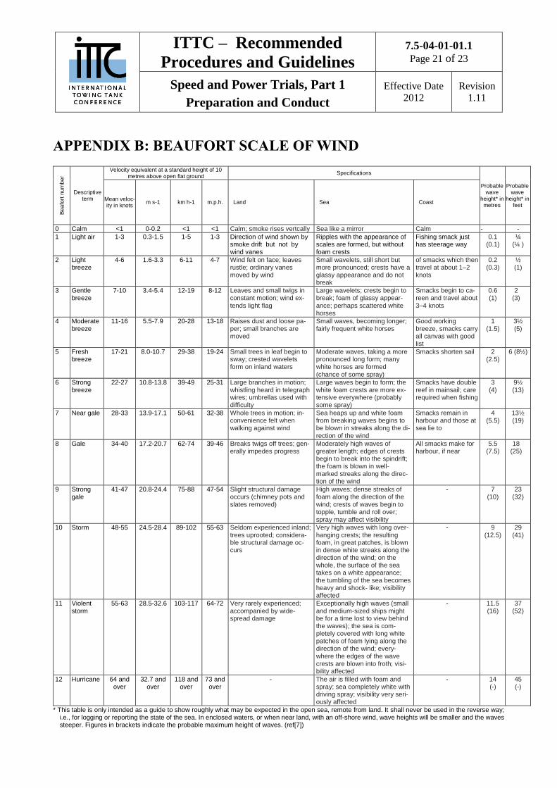
APPENDIX B: BEAUFORT SCALE OF WIND
Be
afo
rt n
um
be
r
Descriptive term
Velocity equivalent at a standard height of 10 metres above open flat ground
Specifications
Probable wave
height* in metres
Probable wave
height* in feet
Mean veloc-ity in knots
m s-1 km h-1 m.p.h. Land Sea Coast
0 Calm <1 0-0.2 <1 <1 Calm; smoke rises vertcally Sea like a mirror Calm - -
1 Light air 1-3 0.3-1.5 1-5 1-3 Direction of wind shown by smoke drift but not by wind vanes
Ripples with the appearance of scales are formed, but without foam crests
Fishing smack just has steerage way
0.1 (0.1)
¼ (¼ )
2 Light breeze
4-6 1.6-3.3 6-11 4-7 Wind felt on face; leaves rustle; ordinary vanes moved by wind
Small wavelets, still short but more pronounced; crests have a glassy appearance and do not break
of smacks which then travel at about 1–2 knots
0.2 (0.3)
½ (1)
3 Gentle breeze
7-10 3.4-5.4 12-19 8-12 Leaves and small twigs in constant motion; wind ex- tends light flag
Large wavelets; crests begin to break; foam of glassy appear-ance; perhaps scattered white horses
Smacks begin to ca-reen and travel about 3–4 knots
0.6 (1)
2 (3)
4 Moderate breeze
11-16 5.5-7.9 20-28 13-18 Raises dust and loose pa-per; small branches are moved
Small waves, becoming longer; fairly frequent white horses
Good working breeze, smacks carry all canvas with good list
1 (1.5)
3½ (5)
5 Fresh breeze
17-21 8.0-10.7 29-38 19-24 Small trees in leaf begin to sway; crested wavelets form on inland waters
Moderate waves, taking a more pronounced long form; many white horses are formed (chance of some spray)
Smacks shorten sail 2 (2.5)
6 (8½)
6 Strong breeze
22-27 10.8-13.8 39-49 25-31 Large branches in motion; whistling heard in telegraph wires; umbrellas used with difficulty
Large waves begin to form; the white foam crests are more ex-tensive everywhere (probably some spray)
Smacks have double reef in mainsail; care required when fishing
3 (4)
9½ (13)
7 Near gale 28-33 13.9-17.1 50-61 32-38 Whole trees in motion; in-convenience felt when walking against wind
Sea heaps up and white foam from breaking waves begins to be blown in streaks along the di-
rection of the wind
Smacks remain in harbour and those at sea lie to
4 (5.5)
13½ (19)
8 Gale 34-40 17.2-20.7 62-74 39-46 Breaks twigs off trees; gen-erally impedes progress
Moderately high waves of greater length; edges of crests begin to break into the spindrift; the foam is blown in well-marked streaks along the direc-tion of the wind
All smacks make for harbour, if near
5.5 (7.5)
18 (25)
9 Strong gale
41-47 20.8-24.4 75-88 47-54 Slight structural damage occurs (chimney pots and slates removed)
High waves; dense streaks of foam along the direction of the wind; crests of waves begin to topple, tumble and roll over; spray may affect visibility
- 7 (10)
23 (32)
10 Storm 48-55 24.5-28.4 89-102 55-63 Seldom experienced inland; trees uprooted; considera-ble structural damage oc-curs
Very high waves with long over- hanging crests; the resulting foam, in great patches, is blown in dense white streaks along the direction of the wind; on the whole, the surface of the sea takes on a white appearance; the tumbling of the sea becomes heavy and shock- like; visibility affected
- 9 (12.5)
29 (41)
11 Violent storm
55-63 28.5-32.6 103-117 64-72 Very rarely experienced; accompanied by wide- spread damage
Exceptionally high waves (small and medium-sized ships might be for a time lost to view behind the waves); the sea is com-pletely covered with long white patches of foam lying along the direction of the wind; every-where the edges of the wave crests are blown into froth; visi-bility affected
- 11.5 (16)
37 (52)
12 Hurricane 64 and over
32.7 and over
118 and over
73 and over
- The air is filled with foam and spray; sea completely white with driving spray; visibility very seri-ously affected
- 14 (-)
45 (-)
* This table is only intended as a guide to show roughly what may be expected in the open sea, remote from land. It shall never be used in the reverse way; i.e., for logging or reporting the state of the sea. In enclosed waters, or when near land, with an off-shore wind, wave heights will be smaller and the waves steeper. Figures in brackets indicate the probable maximum height of waves. (ref[7])

ITTC – Recommended
Procedures and Guidelines 7.5-04-01-01.1
Page 22 of 23
Speed and Power Trials, Part 1
Preparation and Conduct
Effective Date
2012
Revision
1.11
State of the sea
Code figure
Descriptive terms Height* in metres
0 Calm (glassy) 0
1 Calm (rippled) 0 – 0.1
2 Smooth (wavelets) 0.1 – 0.5
3 Slight 0.5 – 1.25
4 Moderate 1.25 – 2.5
5 Rough 2.5 – 4
6 Very rough 4 – 6
7 High 6 – 9
8 Very high 9 –14
9 Phenomenal Over 14
N o t e s:
(1) * These values refer to well-developed wind waves of the open sea. While priority shall be given to the descriptive
terms, these height values may be used for guidance by the observer when reporting the total state of
agitation of the sea resulting from various factors such as wind, swell, currents, angle between swell and
wind, etc.
(2) The exact bounding height shall be assigned for the lower code figure; e.g. a height of 4 m is coded as 5.
ITTC – Recommended
Procedures and Guidelines 7.5-04-01-01.1
Page 23 of 23
Speed and Power Trials, Part 1
Preparation and Conduct
Effective Date
2012
Revision
1.11
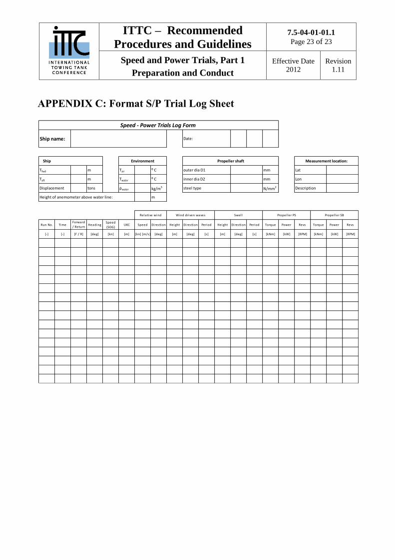
APPENDIX C: Format S/P Trial Log Sheet
Ship name: Date:
Ship
m Tair ⁰ C outer dia D1 mm
m Twater ⁰ C inner dia D2 mm
Displacement tons ρwater kg/m3 steel type N/mm2
m
Run No. TimeForward
/ Return
run
HeadingSpeed
(SOG)UKC Speed Direction Height Direction Period Height Direction Period Torque Power Revs Torque Power Revs
[-] [-] [F / R] [deg] [kn] [m] [kn] [m/s] [deg] [m] [deg] [s ] [m] [deg] [s ] [kNm] [kW] [RPM] [kNm] [kW] [RPM]
Speed - Power Trials Log Form
Propeller shaft Measurement location:
Lat
Lon
Description
Height of anemometer above water line:
Tfwd
Taft
Environment
Relative wind Wind driven waves Swel l Propel ler SBPropel ler PS


