Embed Size (px)
Citation preview
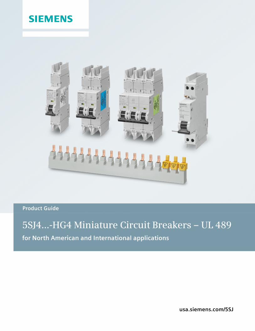
usa.siemens.com/5SJ
Product Guide
5SJ4...-HG4 Miniature Circuit Breakers – UL 489 for North American and International applications
Table of contents
Certifications 3
Description 4
Circuit breaker catalog number nomenclature 5
Product selection – 5SJ41..-.HG40 6
Product selection – 5SJ4...-.HG41 7
Product selection – 5SJ4...-.HG42 8
Product selection – Accessories; auxiliary switch, fault current contact, shunt trip 9
Product Selection – Busbar, connection terminals, protection covers 10
Typical 5SJ4 miniature circuit breaker markings 11
Typical auxiliary switch (AS) and fault signal (FS) contact markings 13
Typical shunt trip markings 14
Typical busbar markings 15
Current ratings at ambient temperatures other than 40ºC 16
Let-through I2t values 17
Power loss 18
Correction factors for rated current at different ambient temperatures 18
Technical specifications 19
Accessory mounting; auxiliary switch, fault current contact, shunt trip 20
Dimensions 21
Limitations of use 22
3
Certifications and Standards
n UL Listed
nUL 489
nCSA 22.2 No. 5-02
nHACR
nIEC/EN 60 898, IEC/EN 60 947-2
Features – UL 489
n Suitable for branch circuit and feeder protection applications
• -.HG40: up to 240 VAC, and 60 VDC (1-pole);
• -.HG41: up to 240 VAC, and 60 VDC (1-pole); and up to 240 VAC, and 125 VDC (2- and 3-pole)
• -.HG42: up to 277 VAC, and 60 VDC (1-pole); and, up to 480/277 VAC and 125 VDC (2- and 3-pole)
ncULus: UL listed and certified to Canadian Standards. File E24314
n HACR rated
nThermal magnetic protection
nHigh interrupting rating:
• VAC: up to 14,000 (Type HSJ) or 10,000 (Type NSJ) Maximum RMS symmetrical amps depending on the device selected
• VDC: up to 10,000 amps (Type HSJ and Type NSJ) at 60/125 VDC
n40°C (104°F) calibration base (industrial applications)
nCan be used for “field wiring” applications, AWG 14 to AWG 4, Copper (Cu) only • -.HG40: suitable for “same polarity” connections only • -.HG41 and -.HG42: suitable for “reverse feed” application No “same polarity” restrictions
5SJ4 miniature circuit breakers are also CE marked according to IEC/EN 60 898 and IEC/EN 60 947-2 making them suitable for use in international applications.
Features – EN/IEC 60 898, EN/IEC 60 947-2
nCE marked
n30°C (86°F) calibration base
nMeets trip characteristics
• -.HG40: B, C and D
• -.HG41 and -.HG42: C and D
nRated voltage
• VAC/DC: 24 minimum
• VDC/pole: 60 maximum
• VAC: 440 maximum
nHigh interrupting rating (Icn) to IEC 60 898-1 of up to 10,000 A AC
nHigh interrupting rating (Icn) to IEC 60 898-1 of up to 15,000 A AC Features – Common
n Available with
• -.HG40: 1-pole
• -.HG41 and -HG42: 1-, 2- or 3-poles
n Available from
• -.HG40 and -.HG41: 0.3 to 63 amps depending on the device selected
• -.HG42: 0.3 to 40 A (C Characteristic); 0.3 to 32A (D characteristic)
nVisible indicator for ON and OFF/Trip
nFinger-safe design
nStandard DIN rail mounting (35 mm)
nIdentical wire screw connections on line and load sides
nCFC and silicone free
Certifications and features
4
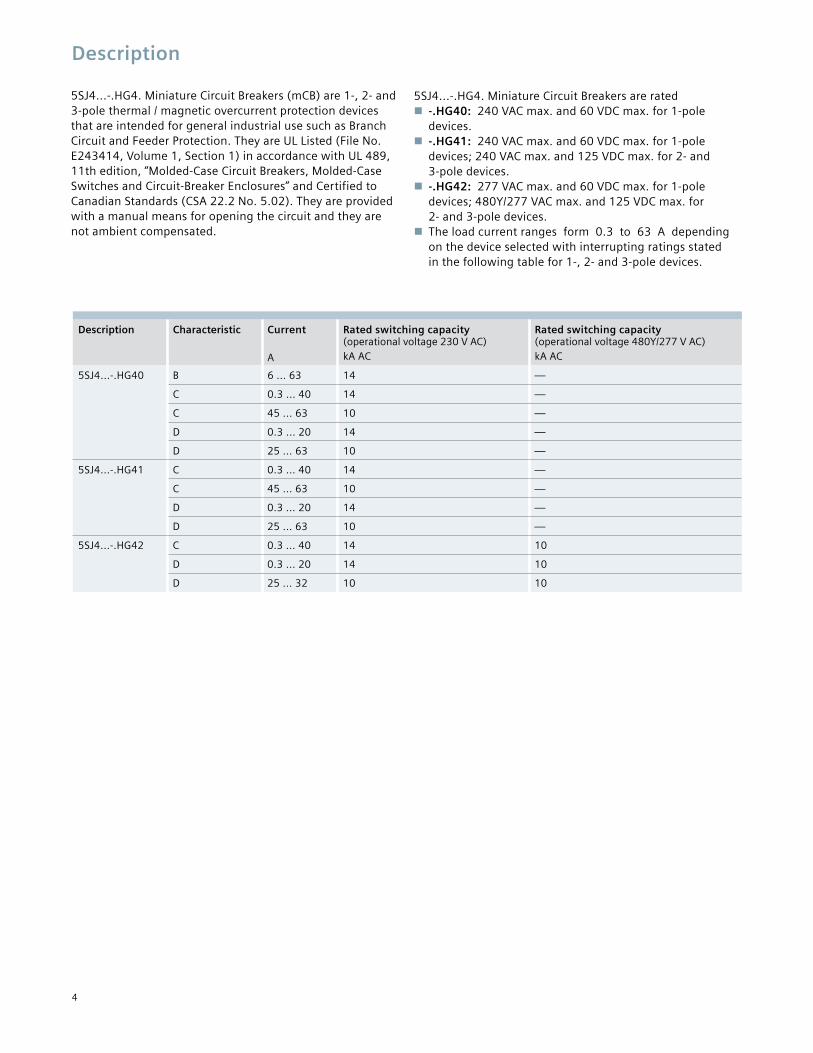
5SJ4...-.HG4. Miniature Circuit Breakers (mCB) are 1-, 2- and 3-pole thermal / magnetic overcurrent protection devices that are intended for general industrial use such as Branch Circuit and Feeder Protection. They are UL Listed (File No. E243414, Volume 1, Section 1) in accordance with UL 489, 11th edition, “Molded-Case Circuit Breakers, Molded-Case Switches and Circuit-Breaker Enclosures” and Certified to Canadian Standards (CSA 22.2 No. 5.02). They are provided with a manual means for opening the circuit and they are not ambient compensated.
5SJ4...-.HG4. Miniature Circuit Breakers are rated n-.HG40: 240 VAC max. and 60 VDC max. for 1-pole devices. n-.HG41: 240 VAC max. and 60 VDC max. for 1-pole devices; 240 VAC max. and 125 VDC max. for 2- and 3-pole devices. n-.HG42: 277 VAC max. and 60 VDC max. for 1-pole devices; 480Y/277 VAC max. and 125 VDC max. for 2- and 3-pole devices. nThe load current ranges form 0.3 to 63 A depending on the device selected with interrupting ratings stated in the following table for 1-, 2- and 3-pole devices.
Description Characteristic Current
A
Rated switching capacity (operational voltage 230 V AC) kA AC
Rated switching capacity (operational voltage 480Y/277 V AC) kA AC
5SJ4...-.HG40 B 6 ... 63 14 —
C 0.3 ... 40 14 —
C 45 ... 63 10 —
D 0.3 ... 20 14 —
D 25 ... 63 10 —
5SJ4...-.HG41 C 0.3 ... 40 14 —
C 45 ... 63 10 —
D 0.3 ... 20 14 —
D 25 ... 63 10 —
5SJ4...-.HG42 C 0.3 ... 40 14 10
D 0.3 ... 20 14 10
D 25 ... 32 10 10
Description
5
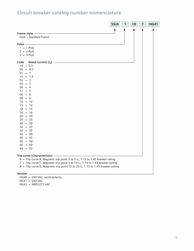
Circuit breaker catalog number nomenclature
5SJ4 1 10 7 HG41
Frame style 5SJ4 – Standard Frame Poles 1 = 1-Pole 2 = 2-Pole 3 = 3-Pole Code Rated current (In) 14 = 0.3 05 = 0.5 01 = 1 15 = 1.6 02 = 2 03 = 3 04 = 4 11 = 5 06 = 6 08 = 8 10 = 10 13 = 13 18 = 15 16 = 16 20 = 20 25 = 25 30 = 30 32 = 32 35 = 35 40 = 40 45 = 45 50 = 50 60 = 60 63 = 63 Trip curve (Characteristic) 6 = Trip curve B, Magnetic trip point 3 to 5 In, 1.13 to 1.45 breaker rating 7 = Trip curve C, Magnetic trip point 5 to 10 In, 1.13 to 1.45 breaker rating 8 = Trip curve D, Magnetic trip point 10 to 20 In, 1.13 to 1.45 breaker rating Version HG40 = 240 VAC, same polarity HG41 = 240 VAC HG42 = 480Y/277 VAC
6
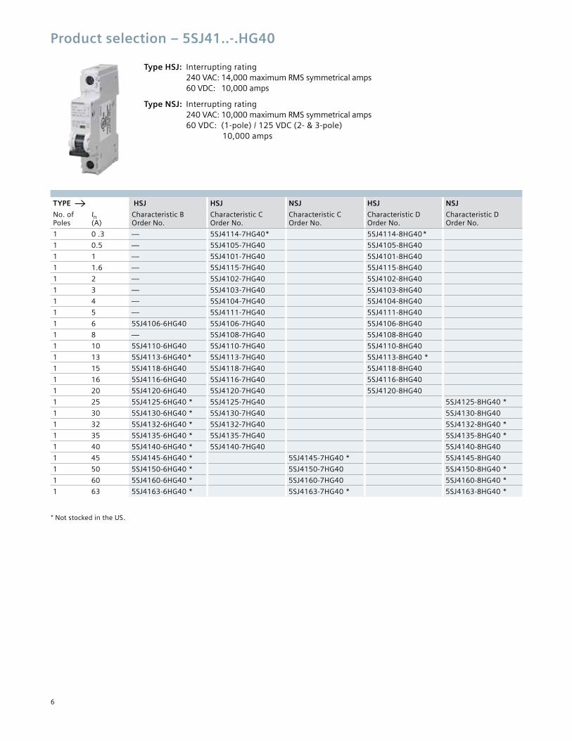
Product selection – 5SJ41..-.HG40
Type HSJ: Interrupting rating 240 VAC: 14,000 maximum RMS symmetrical amps 60 VDC: 10,000 amps
Type NSJ: Interrupting rating 240 VAC: 10,000 maximum RMS symmetrical amps 60 VDC: (1-pole) / 125 VDC (2- & 3-pole) 10,000 amps
TYPE HSJ HSJ NSJ HSJ NSJ
No. of Poles
In (A)
Characteristic B Order No.
Characteristic C Order No.
Characteristic C Order No.
Characteristic D Order No.
Characteristic D Order No.
1 0 .3 — 5SJ4114-7HG40* 5SJ4114-8HG40*
1 0.5 — 5SJ4105-7HG40 5SJ4105-8HG40
1 1 — 5SJ4101-7HG40 5SJ4101-8HG40
1 1.6 — 5SJ4115-7HG40 5SJ4115-8HG40
1 2 — 5SJ4102-7HG40 5SJ4102-8HG40
1 3 — 5SJ4103-7HG40 5SJ4103-8HG40
1 4 — 5SJ4104-7HG40 5SJ4104-8HG40
1 5 — 5SJ4111-7HG40 5SJ4111-8HG40
1 6 5SJ4106-6HG40 5SJ4106-7HG40 5SJ4106-8HG40
1 8 — 5SJ4108-7HG40 5SJ4108-8HG40
1 10 5SJ4110-6HG40 5SJ4110-7HG40 5SJ4110-8HG40
1 13 5SJ4113-6HG40 * 5SJ4113-7HG40 5SJ4113-8HG40 *
1 15 5SJ4118-6HG40 5SJ4118-7HG40 5SJ4118-8HG40
1 16 5SJ4116-6HG40 5SJ4116-7HG40 5SJ4116-8HG40
1 20 5SJ4120-6HG40 5SJ4120-7HG40 5SJ4120-8HG40
1 25 5SJ4125-6HG40 * 5SJ4125-7HG40 5SJ4125-8HG40 *
1 30 5SJ4130-6HG40 * 5SJ4130-7HG40 5SJ4130-8HG40
1 32 5SJ4132-6HG40 * 5SJ4132-7HG40 5SJ4132-8HG40 *
1 35 5SJ4135-6HG40 * 5SJ4135-7HG40 5SJ4135-8HG40 *
1 40 5SJ4140-6HG40 * 5SJ4140-7HG40 5SJ4140-8HG40
1 45 5SJ4145-6HG40 * 5SJ4145-7HG40 * 5SJ4145-8HG40
1 50 5SJ4150-6HG40 * 5SJ4150-7HG40 5SJ4150-8HG40 *
1 60 5SJ4160-6HG40 * 5SJ4160-7HG40 5SJ4160-8HG40 *
1 63 5SJ4163-6HG40 * 5SJ4163-7HG40 * 5SJ4163-8HG40 *
* Not stocked in the US.
7
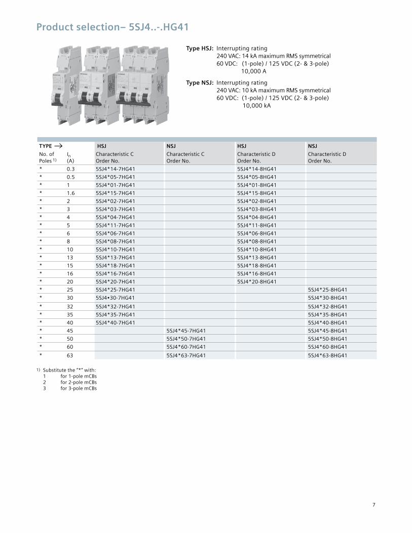
Product selection– 5SJ4..-.HG41
Type HSJ: Interrupting rating 240 VAC: 14 kA maximum RMS symmetrical 60 VDC: (1-pole) / 125 VDC (2- & 3-pole) 10,000 A
Type NSJ: Interrupting rating 240 VAC: 10 kA maximum RMS symmetrical 60 VDC: (1-pole) / 125 VDC (2- & 3-pole) 10,000 kA
TYPE HSJ NSJ HSJ NSJ
No. of Poles 1)
In (A)
Characteristic C Order No.
Characteristic C Order No.
Characteristic D Order No.
Characteristic D Order No.
* 0.3 5SJ4*14-7HG41 5SJ4*14-8HG41
* 0.5 5SJ4*05-7HG41 5SJ4*05-8HG41
* 1 5SJ4*01-7HG41 5SJ4*01-8HG41
* 1.6 5SJ4*15-7HG41 5SJ4*15-8HG41
* 2 5SJ4*02-7HG41 5SJ4*02-8HG41
* 3 5SJ4*03-7HG41 5SJ4*03-8HG41
* 4 5SJ4*04-7HG41 5SJ4*04-8HG41
* 5 5SJ4*11-7HG41 5SJ4*11-8HG41
* 6 5SJ4*06-7HG41 5SJ4*06-8HG41
* 8 5SJ4*08-7HG41 5SJ4*08-8HG41
* 10 5SJ4*10-7HG41 5SJ4*10-8HG41
* 13 5SJ4*13-7HG41 5SJ4*13-8HG41
* 15 5SJ4*18-7HG41 5SJ4*18-8HG41
* 16 5SJ4*16-7HG41 5SJ4*16-8HG41
* 20 5SJ4*20-7HG41 5SJ4*20-8HG41
* 25 5SJ4*25-7HG41 5SJ4*25-8HG41
* 30 5SJ4•30-7HG41 5SJ4*30-8HG41
* 32 5SJ4*32-7HG41 5SJ4*32-8HG41
* 35 5SJ4*35-7HG41 5SJ4*35-8HG41
* 40 5SJ4*40-7HG41 5SJ4*40-8HG41
* 45 5SJ4*45-7HG41 5SJ4*45-8HG41
* 50 5SJ4*50-7HG41 5SJ4*50-8HG41
* 60 5SJ4*60-7HG41 5SJ4*60-8HG41
* 63 5SJ4*63-7HG41 5SJ4*63-8HG41
1) Substitute the “*” with: 1 for 1-pole mCBs 2 for 2-pole mCBs 3 for 3-pole mCBs
8
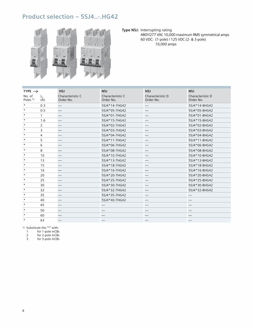
Product selection – 5SJ4..-.HG42
Type NSJ: Interrupting rating 480Y/277 VAC 10,000 maximum RMS symmetrical amps 60 VDC: (1-pole) / 125 VDC (2- & 3-pole) 10,000 amps
TYPE HSJ NSJ HSJ NSJ
No. of Poles 1)
In (A)
Characteristic C Order No.
Characteristic C Order No.
Characteristic D Order No.
Characteristic D Order No.
* 0.3 — 5SJ4*14-7HG42 — 5SJ4*14-8HG42
* 0.5 — 5SJ4*05-7HG42 — 5SJ4*05-8HG42
* 1 — 5SJ4*01-7HG42 — 5SJ4*01-8HG42
* 1.6 — 5SJ4*15-7HG42 — 5SJ4*15-8HG42
* 2 — 5SJ4*02-7HG42 — 5SJ4*02-8HG42
* 3 — 5SJ4*03-7HG42 — 5SJ4*03-8HG42
* 4 — 5SJ4*04-7HG42 — 5SJ4*04-8HG42
* 5 — 5SJ4*11-7HG42 — 5SJ4*11-8HG42
* 6 — 5SJ4*06-7HG42 — 5SJ4*06-8HG42
* 8 — 5SJ4*08-7HG42 — 5SJ4*08-8HG42
* 10 — 5SJ4*10-7HG42 — 5SJ4*10-8HG42
* 13 — 5SJ4*13-7HG42 — 5SJ4*13-8HG42
* 15 — 5SJ4*18-7HG42 — 5SJ4*18-8HG42
* 16 — 5SJ4*16-7HG42 — 5SJ4*16-8HG42
* 20 — 5SJ4*20-7HG42 — 5SJ4*20-8HG42
* 25 — 5SJ4*25-7HG42 — 5SJ4*25-8HG42
* 30 — 5SJ4*30-7HG42 — 5SJ4*30-8HG42
* 32 — 5SJ4*32-7HG42 — 5SJ4*32-8HG42
* 35 — 5SJ4*35-7HG42 — —
* 40 — 5SJ4*40-7HG42 — —
* 45 — — — —
* 50 — — — —
* 60 — — — —
* 63 — — — —
1) Substitute the “*” with: 1 for 1-pole mCBs 2 for 2-pole mCBs 3 for 3-pole mCBs
9
TYPE HSJ NSJ HSJ NSJ
No. of Poles 1)
In (A)
Characteristic C Order No.
Characteristic C Order No.
Characteristic D Order No.
Characteristic D Order No.
* 0.3 — 5SJ4*14-7HG42 — 5SJ4*14-8HG42
* 0.5 — 5SJ4*05-7HG42 — 5SJ4*05-8HG42
* 1 — 5SJ4*01-7HG42 — 5SJ4*01-8HG42
* 1.6 — 5SJ4*15-7HG42 — 5SJ4*15-8HG42
* 2 — 5SJ4*02-7HG42 — 5SJ4*02-8HG42
* 3 — 5SJ4*03-7HG42 — 5SJ4*03-8HG42
* 4 — 5SJ4*04-7HG42 — 5SJ4*04-8HG42
* 5 — 5SJ4*11-7HG42 — 5SJ4*11-8HG42
* 6 — 5SJ4*06-7HG42 — 5SJ4*06-8HG42
* 8 — 5SJ4*08-7HG42 — 5SJ4*08-8HG42
* 10 — 5SJ4*10-7HG42 — 5SJ4*10-8HG42
* 13 — 5SJ4*13-7HG42 — 5SJ4*13-8HG42
* 15 — 5SJ4*18-7HG42 — 5SJ4*18-8HG42
* 16 — 5SJ4*16-7HG42 — 5SJ4*16-8HG42
* 20 — 5SJ4*20-7HG42 — 5SJ4*20-8HG42
* 25 — 5SJ4*25-7HG42 — 5SJ4*25-8HG42
* 30 — 5SJ4*30-7HG42 — 5SJ4*30-8HG42
* 32 — 5SJ4*32-7HG42 — 5SJ4*32-8HG42
* 35 — 5SJ4*35-7HG42 — —
* 40 — 5SJ4*40-7HG42 — —
* 45 — — — —
* 50 — — — —
* 60 — — — —
* 63 — — — —
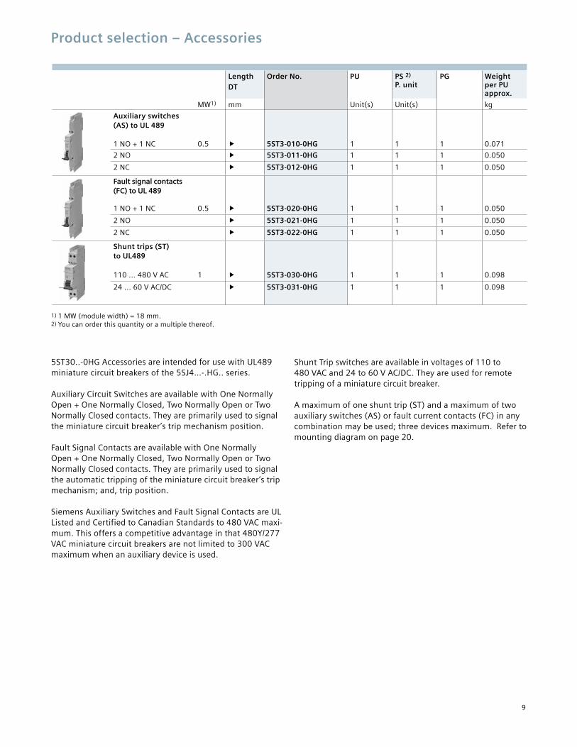
Product selection – Accessories
Length DT
Order No. PU PS 2)
P. unitPG Weight
per PU approx.
MW1) mm Unit(s) Unit(s) kg
Auxiliary switches (AS) to UL 489
1 NO + 1 NC 0.5 � 5ST3-010-0HG 1 1 1 0.071
2 NO � 5ST3-011-0HG 1 1 1 0.050
2 NC � 5ST3-012-0HG 1 1 1 0.050
Fault signal contacts (FC) to UL 489
1 NO + 1 NC 0.5 � 5ST3-020-0HG 1 1 1 0.050
2 NO � 5ST3-021-0HG 1 1 1 0.050
2 NC � 5ST3-022-0HG 1 1 1 0.050
Shunt trips (ST) to UL489
110 ... 480 V AC 1 � 5ST3-030-0HG 1 1 1 0.098
24 ... 60 V AC/DC � 5ST3-031-0HG 1 1 1 0.098
5ST30..-0HG Accessories are intended for use with UL489 miniature circuit breakers of the 5SJ4…-.HG.. series. Auxiliary Circuit Switches are available with One Normally Open + One Normally Closed, Two Normally Open or Two Normally Closed contacts. They are primarily used to signal the miniature circuit breaker’s trip mechanism position. Fault Signal Contacts are available with One Normally Open + One Normally Closed, Two Normally Open or Two Normally Closed contacts. They are primarily used to signal the automatic tripping of the miniature circuit breaker’s trip mechanism; and, trip position. Siemens Auxiliary Switches and Fault Signal Contacts are UL Listed and Certified to Canadian Standards to 480 VAC maxi-mum. This offers a competitive advantage in that 480Y/277 VAC miniature circuit breakers are not limited to 300 VAC maximum when an auxiliary device is used.
Shunt Trip switches are available in voltages of 110 to 480 VAC and 24 to 60 V AC/DC. They are used for remote tripping of a miniature circuit breaker. A maximum of one shunt trip (ST) and a maximum of two auxiliary switches (AS) or fault current contacts (FC) in any combination may be used; three devices maximum. Refer to mounting diagram on page 20.
1) 1 MW (module width) = 18 mm. 2) You can order this quantity or a multiple thereof.
10
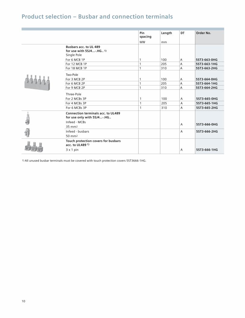
Product selection – Busbar and connection terminals
Pin spacing
Length DT Order No.
MW mm
Busbars acc. to UL 489 for use with 5SJ4...-.HG.. 1) Single Pole
For 6 MCB 1P 1 100 A 5ST3-663-0HGFor 12 MCB 1P 1 205 A 5ST3-663-1HGFor 18 MCB 1P 1 310 A 5ST3-663-2HG Two-PoleFor 3 MCB 2P 1 100 A 5ST3-664-0HGFor 6 MCB 2P 1 205 A 5ST3-664-1HGFor 9 MCB 2P 1 310 A 5ST3-664-2HG Three-PoleFor 2 MCBs 3P 1 100 A 5ST3-665-0HGFor 4 MCBs 3P 1 205 A 5ST3-665-1HGFor 6 MCBs 3P 1 310 A 5ST3-665-2HG
Connection terminals acc. to UL489 for use only with 5SJ4...-.HG..
Infeed - MCBs
35 mm2A 5ST3-666-0HG
Infeed - busbars
50 mm2
A 5ST3-666-2HG
Touch protection covers for busbars acc. to UL489 1)
3 x 1 pin A 5ST3-666-1HG
1) All unused busbar terminals must be covered with touch protection covers 5ST3666-1HG.
11
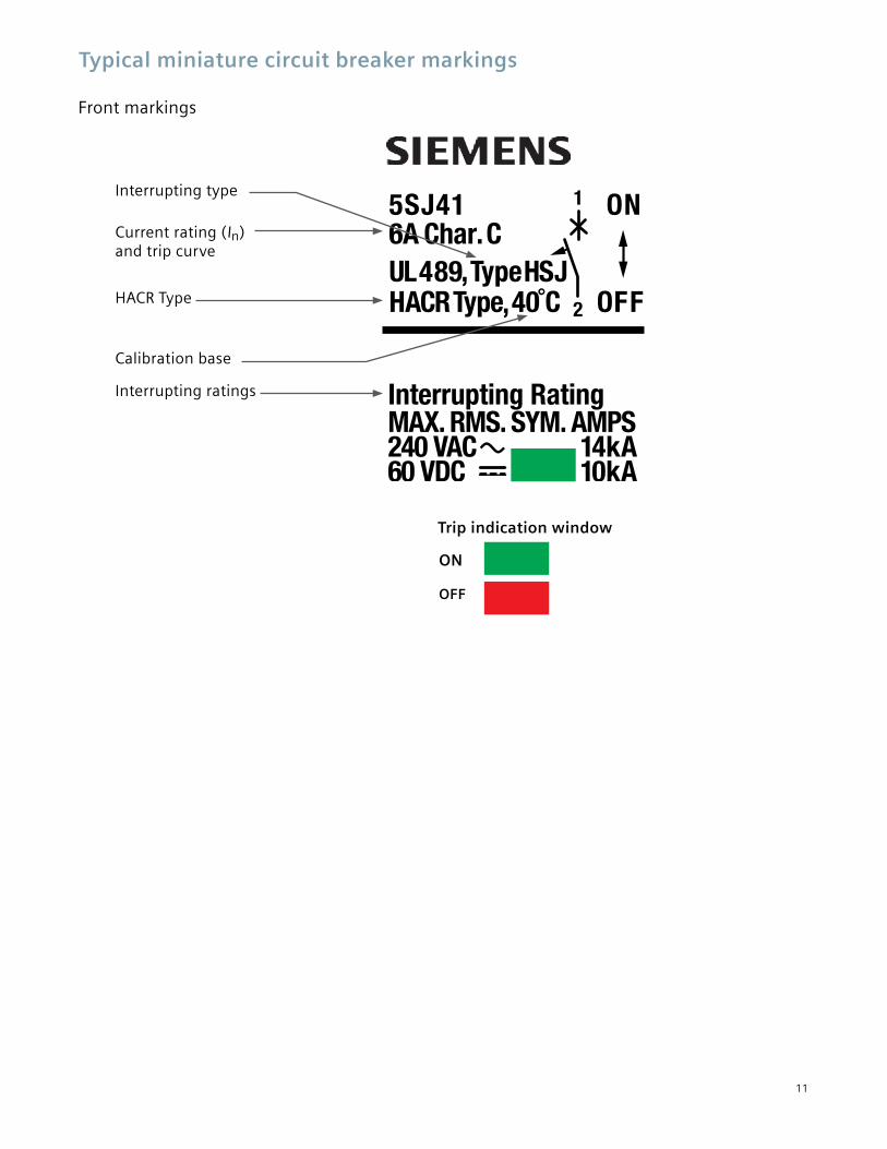
Typical miniature circuit breaker markings
Front markings
Interrupting type
Current rating (In) and trip curve
HACR Type
Calibration base
Interrupting ratings
Trip indication window
ON
OFF
12
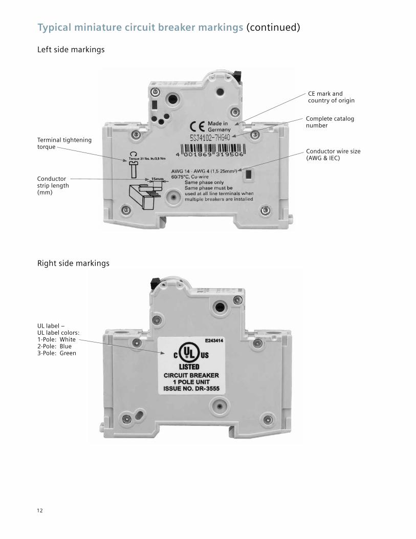
Typical miniature circuit breaker markings (continued)
Left side markings
Right side markings
CE mark and country of origin
Terminal tightening torque
Conductor strip length (mm)
Complete catalog number
Conductor wire size (AWG & IEC)
UL label – UL label colors: 1-Pole: White 2-Pole: Blue 3-Pole: Green
5ST301. AS
1422
2113
13
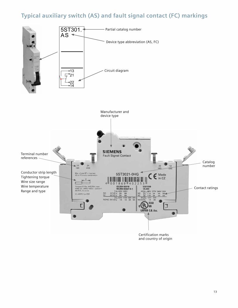
Typical auxiliary switch (AS) and fault signal contact (FC) markings
Circuit diagram
Manufacturer and device type
Certification marks and country of origin
Contact ratings
Catalog number
Partial catalog number
Device type abbreviation (AS, FC)
CE mark and country of origin
Complete catalog number
Conductor strip length Tightening torque Wire size range Wire temperature Range and type
Terminal number references
14
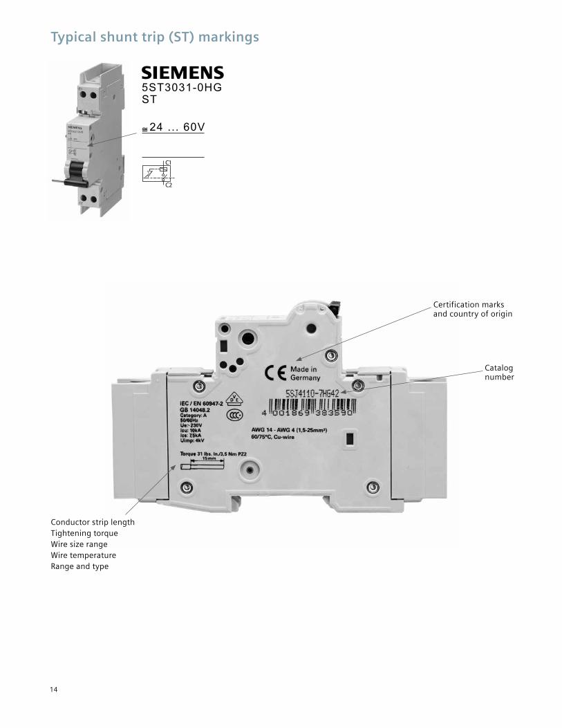
Typical shunt trip (ST) markings
C1
C2
s
5ST3031-0HG ST
24 ... 60V≅
Certification marks and country of origin
Conductor strip length Tightening torque Wire size range Wire temperature Range and type
Catalog number
15
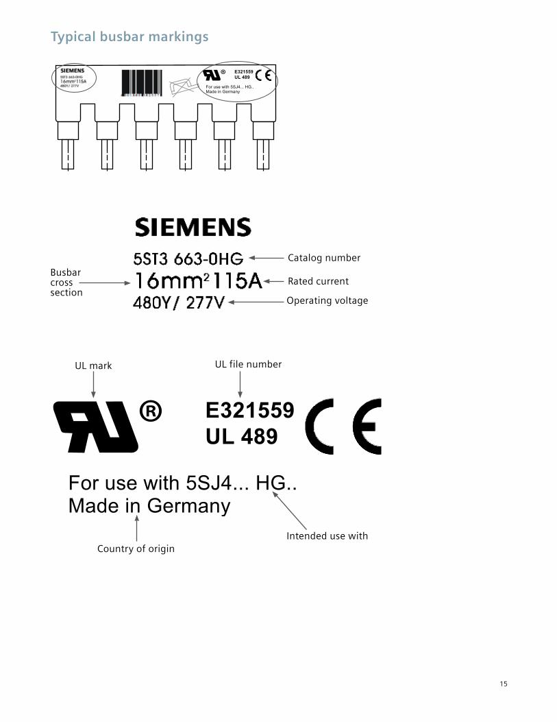
Typical busbar markings
Operating voltage
Intended use with
Rated current
Country of origin
Busbar cross section
UL mark
Catalog number
UL file number
Certification marks and country of origin
Catalog number
16
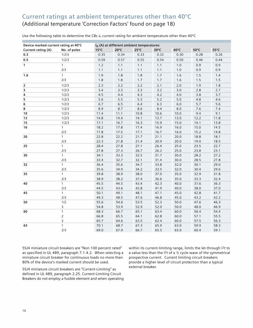
Current ratings at ambient temperatures other than 40°C (Additional temperature ‘Correction Factors’ found on page 18)
Use the following table to determine the CBs In current rating for ambient temperature other than 40ºC
5SJ4 miniature circuit breakers are “Non 100 percent rated” as specified in UL 489, paragraph 7.1.4.2. When selecting a miniature circuit breaker for continuous loads no more than 80% of the device’s marked current should be used.
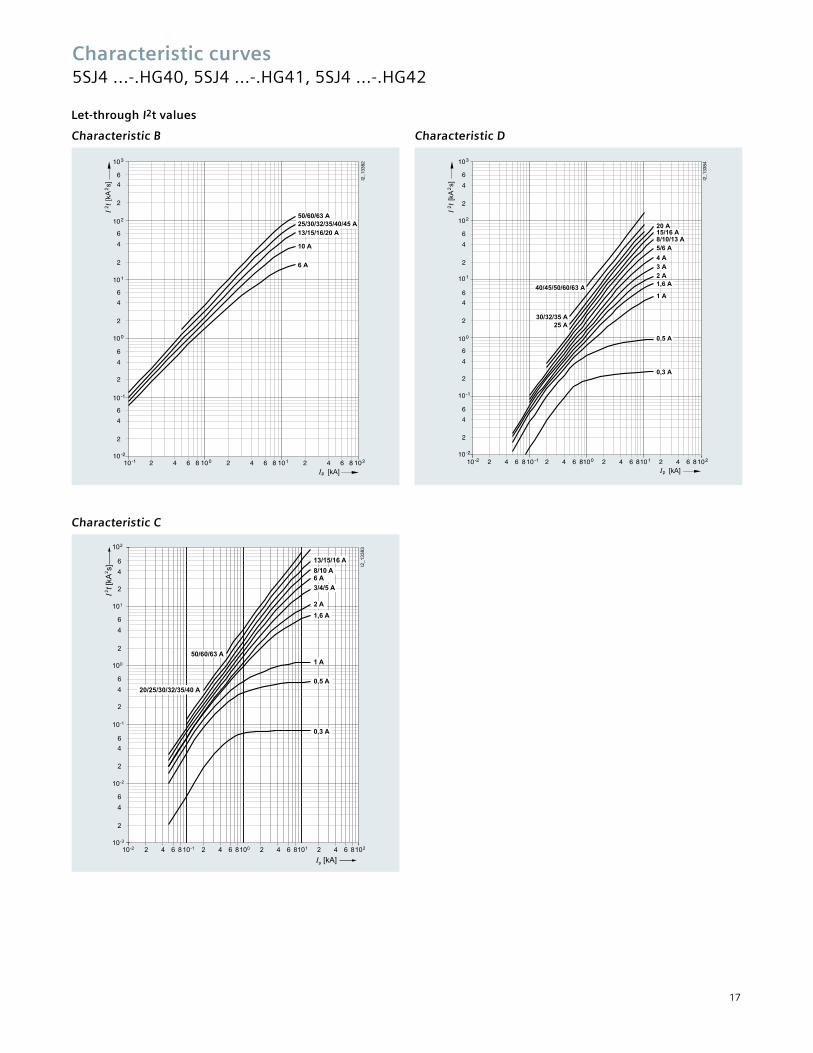
5SJ4 miniature circuit breakers are “Current-Limiting” as defined in UL 489, paragraph 2.25. Current-Limiting Circuit Breakers do not employ a fusible element and when operating
within its current-limiting range, limits the let-through I2t to a value less than the I2t of a ½ cycle wave of the symmetrical prospective current. Current limiting circuit breakers provide a higher level of circuit protection than a typical external breaker.
Device marked current rating at 40ºC In (A) at different ambient temperaturesCurrent rating (A) No. of poles 15ºC 20ºC 25ºC 30ºC 40ºC 50ºC 55ºC0.3 1/2/3 0.35 0.34 0.33 0.32 0.30 0.28 0.26
0.5 1/2/3 0.59 0.57 0.55 0.54 0.50 0.46 0.44
1 1 1.2 1.1 1.1 1.1 1.0 0.9 0.92/3 1.1 1.1 1.1 1.1 1.0 0.9 0.9
1.6 1 1.9 1.8 1.8 1.7 1.6 1.5 1.42/3 1.8 1.8 1.7 1.7 1.6 1.5 1.5
2 1/2/3 2.3 2.2 2.2 2.1 2.0 1.9 1.83 1/2/3 3.4 3.3 3.3 3.2 3.0 2.8 2.74 1/2/3 4.5 4.4 4.3 4.2 4.0 3.8 3.75 1/2/3 5.6 5.5 5.3 5.2 5.0 4.8 4.66 1/2/3 6.7 6.5 6.4 6.3 6.0 5.7 5.68 1/2/3 8.9 8.7 8.6 8.4 8.0 7.6 7.410 1/2/3 11.4 11.1 10.8 10.6 10.0 9.4 9.113 1/2/3 14.8 14.4 14.1 13.7 13.0 12.2 11.815 1/2/3 17.1 16.7 16.3 15.9 15.0 14.1 13.816 1 18.2 17.8 17.4 16.9 16.0 15.0 14.5
2/3 17.8 17.5 17.1 16.7 16.0 15.2 14.820 1 22.8 22.2 21.7 21.1 20.0 18.8 18.1
2/3 22.3 21.8 21.4 20.9 20.0 19.0 18.525 1 28.4 27.8 27.1 26.4 25.0 23.5 22.7
2/3 27.8 27.3 26.7 26.2 25.0 23.8 23.130 1 34.1 33.3 32.5 31.7 30.0 28.2 27.2
2/3 33.4 32.7 32.1 31.4 30.0 28.5 27.832 1 36.4 35.6 34.7 33.8 32.0 30.1 29.0
2/3 35.6 34.9 34.2 33.5 32.0 30.4 29.635 1 39.8 38.9 38.0 37.0 35.0 32.9 31.8
2/3 38.9 38.2 37.4 36.6 35.0 33.3 32.440 1 45.5 44.5 43.4 42.3 40.0 37.6 36.3
2/3 44.5 43.6 42.8 41.9 40.0 38.0 37.045 1 50.1 49.1 48.1 47.1 45.0 42.8 41.7
2/3 49.3 48.5 47.6 46.8 45.0 43.2 42.250 1/2 55.6 54.6 53.5 52.3 50.0 47.6 46.3
3 54.8 53.9 52.9 52.0 50.0 48.0 46.960 1 68.3 66.7 65.1 63.4 60.0 56.4 54.4
2 66.8 65.5 64.1 62.8 60.0 57.1 55.53 65.7 64.6 63.5 62.4 60.0 57.5 56.3
63 1 70.1 68.7 67.3 65.9 63.0 59.9 58.32/3 69.0 67.9 66.7 65.5 63.0 60.4 59.1
17
Characteristic curves5SJ4 ...-.HG40, 5SJ4 ...-.HG41, 5SJ4 ...-.HG42
Let-through I2t values
Characteristic B
Characteristic C
Characteristic D
I2_1
3382
50/60/63 A
10 A
6 A
10 -1
10 -2
2
46
10 0
2
46
10 1
2
46
10 2
2
46
10 3
2
46
[kA
2 s]
10 -1 2 4 6 8 2 4 6 8 2 4 6 810
0 10 1 10
2
p [kA]
13/15/16/20 A25/30/32/35/40/45 A
t 2
I2_1
3383
10
-2
10
-2
10
-3
2 4 6
2
4
6
10
-1
2
4
6
10
0
2
4
6
10
1
2
4
6
10
2
2
4
6
8 2 4 6 8 2 4 6 8 2 4 6 8 10
-1 10
0 10
1 10
2
Ip [kA]
I 2 t [
kA 2 s]
50/60/63 A
8/10 A 6 A
2 A
3/4/5 A
1,6 A
1 A
0,5 A
0,3 A
13/15/16 A
20/25/30/32/35/40 A
10 1
I2_1
3384
30/32/35 A
8/10/13 A
2 A3 A4 A
5/6 A
1,6 A
20 A
25 A
1 A
0,5 A
0,3 A
15/16 A
40/45/50/60/63 A
10 -1
10 -2
2
46
10 0
2
46
10 1
2
46
10 2
2
46
10 3
2
46
[kA
2 s]
10 -2 10
-12 4 6 8 2 4 6 8 2 4 6 8 2 4 6 810 0 10
2
p [kA]
t 2
Curve 4
Curve 3
Curve 2
Curve 1
Red
uctio
n F
acto
r
Ambient Temperature [°C]
-20 -10 00,8
0,9
1,0
1,1
1,2
1,3
1,4
2010 4030 50 60
I2_1
812
0
18
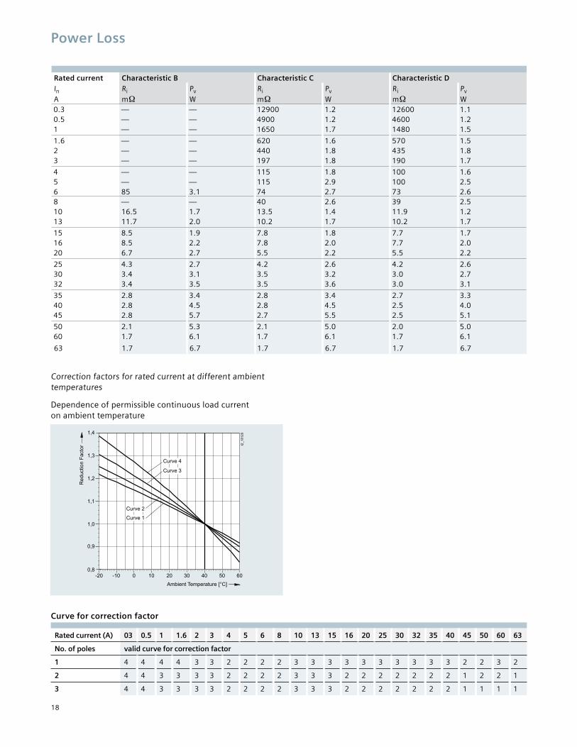
Power Loss
Rated current Characteristic B Characteristic C Characteristic DIn Ri Pv Ri Pv Ri Pv
A m W m W m W0.3 — — 12900 1.2 12600 1.10.5 — — 4900 1.2 4600 1.21 — — 1650 1.7 1480 1.5
1.6 — — 620 1.6 570 1.52 — — 440 1.8 435 1.83 — — 197 1.8 190 1.7
4 — — 115 1.8 100 1.65 — — 115 2.9 100 2.56 85 3.1 74 2.7 73 2.68 — — 40 2.6 39 2.510 16.5 1.7 13.5 1.4 11.9 1.213 11.7 2.0 10.2 1.7 10.2 1.7
15 8.5 1.9 7.8 1.8 7.7 1.716 8.5 2.2 7.8 2.0 7.7 2.020 6.7 2.7 5.5 2.2 5.5 2.2
25 4.3 2.7 4.2 2.6 4.2 2.630 3.4 3.1 3.5 3.2 3.0 2.732 3.4 3.5 3.5 3.6 3.0 3.1
35 2.8 3.4 2.8 3.4 2.7 3.340 2.8 4.5 2.8 4.5 2.5 4.045 2.8 5.7 2.7 5.5 2.5 5.1
50 2.1 5.3 2.1 5.0 2.0 5.060 1.7 6.1 1.7 6.1 1.7 6.1
63 1.7 6.7 1.7 6.7 1.7 6.7
Correction factors for rated current at different ambient temperatures
Dependence of permissible continuous load current on ambient temperature
Curve for correction factor
Rated current (A) 03 0.5 1 1.6 2 3 4 5 6 8 10 13 15 16 20 25 30 32 35 40 45 50 60 63
No. of poles valid curve for correction factor
1 4 4 4 4 3 3 2 2 2 2 3 3 3 3 3 3 3 3 3 3 2 2 3 2
2 4 4 3 3 3 3 2 2 2 2 3 3 3 2 2 2 2 2 2 2 1 2 2 1
3 4 4 3 3 3 3 2 2 2 2 3 3 3 2 2 2 2 2 2 2 1 1 1 1
19
Rated current (A) 03 0.5 1 1.6 2 3 4 5 6 8 10 13 15 16 20 25 30 32 35 40 45 50 60 63
No. of poles valid curve for correction factor
1 4 4 4 4 3 3 2 2 2 2 3 3 3 3 3 3 3 3 3 3 2 2 3 2
2 4 4 3 3 3 3 2 2 2 2 3 3 3 2 2 2 2 2 2 2 1 2 2 1
3 4 4 3 3 3 3 2 2 2 2 3 3 3 2 2 2 2 2 2 2 1 1 1 1
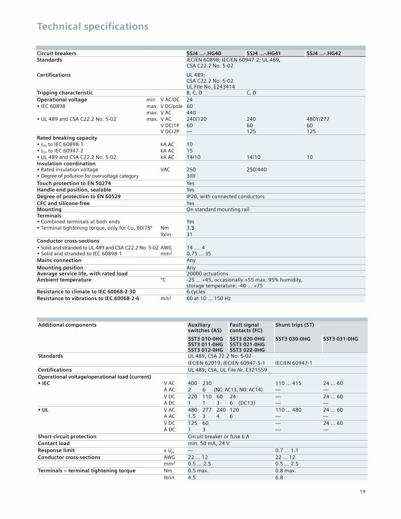
Technical specifications
Circuit breakers 5SJ4 ...-.HG40 5SJ4 ...-.HG41 5SJ4 ...-.HG42Standards IEC/EN 60898; IEC/EN 60947-2; UL 489,
CSA C22.2 No. 5-02
Certifications UL 489; CSA C22.2 No. 5-02 UL FIle No. E243414
Tripping characteristic B, C, D C, DOperational voltage min V AC/DC 24• IEC 60898 max. V DC/pole 60
max. V AC 440• UL 489 and CSA C22.2 No. 5-02 max. V AC 240/120 240 480Y/277
V DC/1P 60 60 60V DC/2P — 125 125
Rated breaking capacity• Icn to IEC 60898-1 kA AC 10• Icu to IEC 60947-2 kA AC 15• UL 489 and CSA C22.2 No. 5-02 kA AC 14/10 14/10 10Insulation coordination• Rated insulation voltage VAC 250 250/440• Degree of pollution for overvoltage category 3/IIITouch protection to EN 50274 YesHandle end position, sealable YesDegree of protection to EN 60529 IP20, with connected conductorsCFC and silicone-free YesMounting On standard mounting railTerminals• Combined terminals at both ends Yes• Terminal tightening torque, only for Cu, 60/75º Nm 3.5
lb/in 31Conductor cross-sections• Solid and stranded to UL 489 and CSA C22.2 No. 5-02 AWG 14 .... 4• Solid and stranded to IEC 60898-1 mm2 0.75 ... 35Mains connection Any
Mounting position AnyAverage service life, with rated load 20000 actuationsAmbient temperature ºC -25 ... +45, occasionally +55 max. 95% humidity,
storage temperature: -40 ... +75Resistance to climate to IEC 60068-2-30 6 cyclesResistance to vibrations to IEC 60068-2-6 m/s2 60 at 10 ... 150 Hz
Additional components Auxiliary switches (AS)
Fault signal contacts (FC)
Shunt trips (ST)
5ST3 010-0HG 5ST3 011-0HG 5ST3 012-0HG
5ST3 020-0HG 5ST3 021-0HG 5ST3 022-0HG
5ST3 030-0HG 5ST3 031-0HG
Standards UL 489, CSA 22.2 No. 5-02IEC/EN 62019, IEC/EN 60947-5-1 IEC/EN 60947-1
Certifications UL 489; CSA, UL File Nr. E321559Operational voltage/operational load (current)• IEC V AC 400 230 110 ... 415 24 ... 60
A AC 2 6 (NC: AC13, NO: AC14) — —V DC 220 110 60 24 — 24 ... 60A DC 1 1 3 6 (DC13) — —
• UL V AC 480 277 240 120 110 ... 480 24 ... 60A AC 1.5 3 4 6 — —V DC 125 60 — 24 ... 60A DC 1 3 — —
Short-circuit protection Circuit breaker or fuse 6 AContact load min. 50 mA, 24 VResponse limit x Un — 0.7 ... 1.1Conductor cross-sections AWG 22 ... 12 22 ... 12
mm2 0.5 ... 2.5 0.5 ... 2.5Terminals – terminal tightening torque Nm 0.5 max. 0.8 max.
lb/in. 4.5 6.8
20
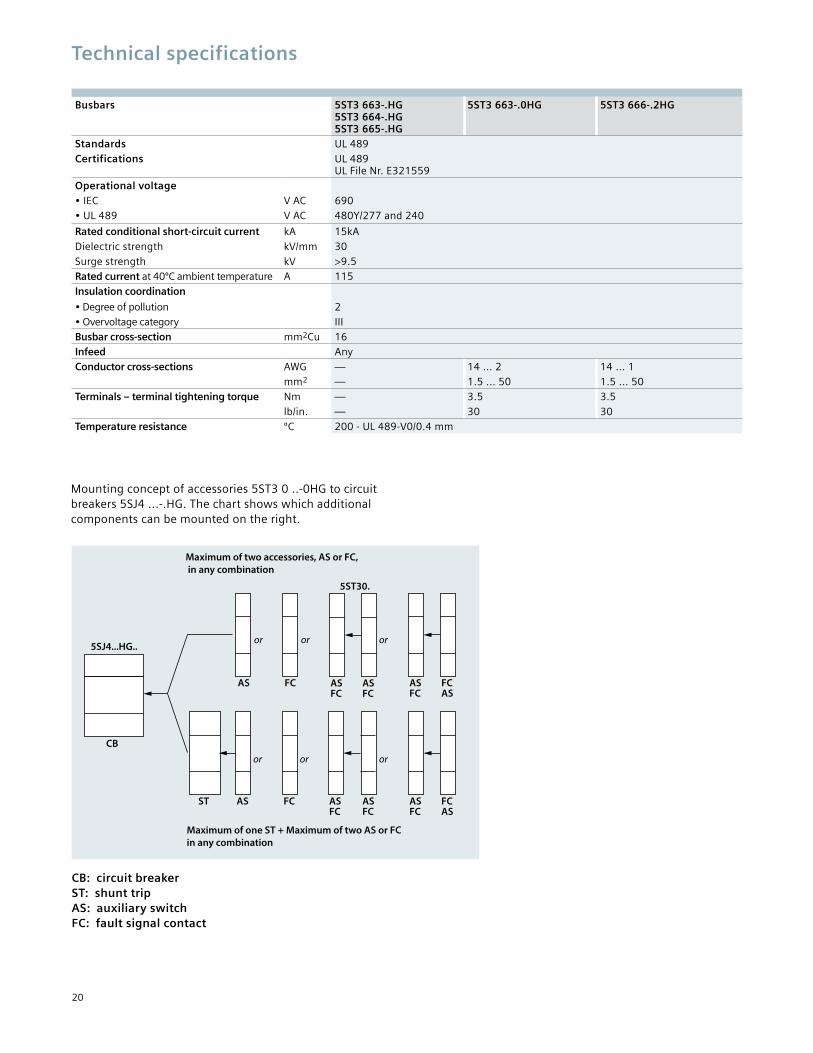
Busbars 5ST3 663-.HG 5ST3 664-.HG 5ST3 665-.HG
5ST3 663-.0HG 5ST3 666-.2HG
Standards UL 489Certifications UL 489
UL File Nr. E321559Operational voltage• IEC V AC 690• UL 489 V AC 480Y/277 and 240
Rated conditional short-circuit current kA 15kADielectric strength kV/mm 30Surge strength kV >9.5Rated current at 40ºC ambient temperature A 115Insulation coordination
• Degree of pollution 2• Overvoltage category IIIBusbar cross-section mm2Cu 16Infeed AnyConductor cross-sections AWG — 14 ... 2 14 ... 1
mm2 — 1.5 ... 50 1.5 ... 50Terminals – terminal tightening torque Nm — 3.5 3.5
lb/in. — 30 30Temperature resistance ºC 200 - UL 489-V0/0.4 mm
Mounting concept of accessories 5ST3 0 ..-0HG to circuit breakers 5SJ4 ...-.HG. The chart shows which additional components can be mounted on the right.
Technical specifications
CB: circuit breaker ST: shunt trip AS: auxiliary switch FC: fault signal contact
5SJ4...HG..
CB
AS
or
FC AS FC
AS FC
or or
AS FC
AS FC
or
AS FC
FC AS
AS FC
FC AS
ST AS
or
FC
or
Maximum of two accessories, AS or FC, in any combination
Maximum of one ST + Maximum of two AS or FC in any combination
5ST30.
21
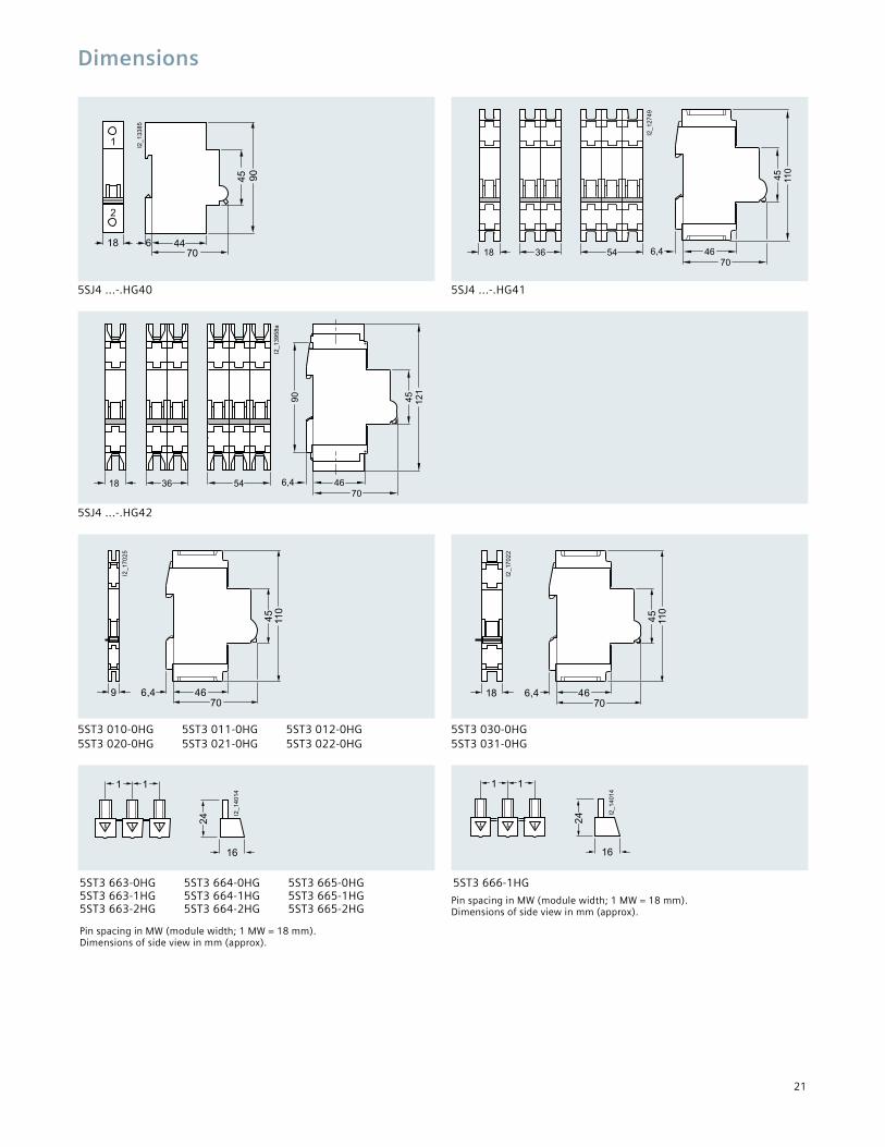
Dimensions
5SJ4 ...-.HG40 5SJ4 ...-.HG41
5SJ4 ...-.HG42
5ST3 010-0HG 5ST3 011-0HG 5ST3 012-0HG 5ST3 020-0HG 5ST3 021-0HG 5ST3 022-0HG
5ST3 030-0HG 5ST3 031-0HG
5ST3 663-0HG 5ST3 664-0HG 5ST3 665-0HG 5ST3 663-1HG 5ST3 664-1HG 5ST3 665-1HG 5ST3 663-2HG 5ST3 664-2HG 5ST3 665-2HG
5ST3 666-1HG
Pin spacing in MW (module width; 1 MW = 18 mm). Dimensions of side view in mm (approx).
18 36 54
I2_12749
45 110
466,470
4470
645 90
I2_13385
18
1
224
1 1
I2_14014
16
24
1 1
I2_14014
16
Pin spacing in MW (module width; 1 MW = 18 mm). Dimensions of side view in mm (approx).
I2_13958a
45 121
90
54 466,470
3618
9 6,4 46
45
110
70
I2_1
702
5
18 6,4 46
45
110
70
I2_1
702
2

22
Limitations of use
The information provided in this product profile contains descriptions or characteristics of performance which in case of actual use do not always apply as described or which may change as a result of further development of the products. An obligation to provide the respective characteristics shall only exist if expressly agreed in the terms of contract. Availability and technical specifications are subject to change without notice. All products designations may be trademarks or product names of Siemens AG or supplier companies whose use by third parties for their own purposes could violate the rights of the owners.

Siemens Industry, Inc. 5400 Triangle Parkway Norcross, GA 30092 1-800-241-4453 [email protected]
Subject to change without prior notice.Order No: PDCA-5SJ4U-1014 All rights reserved. Printed in USA. ©2014 Siemens Industry, Inc.
The information provided in this brochure contains merely general descriptions or characteristics of performance which in case of actual use do not always apply as described or which may change as a result of further development of the products. An obligation to provide the respectivecharacteristics shall only exist if expressly agreed in the terms of contract.
Siemens is a registered trademark of Siemens AG. Product names mentioned may be trademarks or registered trademarks of their respective companies. Specificationsare subject to change without notice.usa.siemens.com/5SJ


