Embed Size (px)
Citation preview
0214770.2018
2018 Owner’s Manual

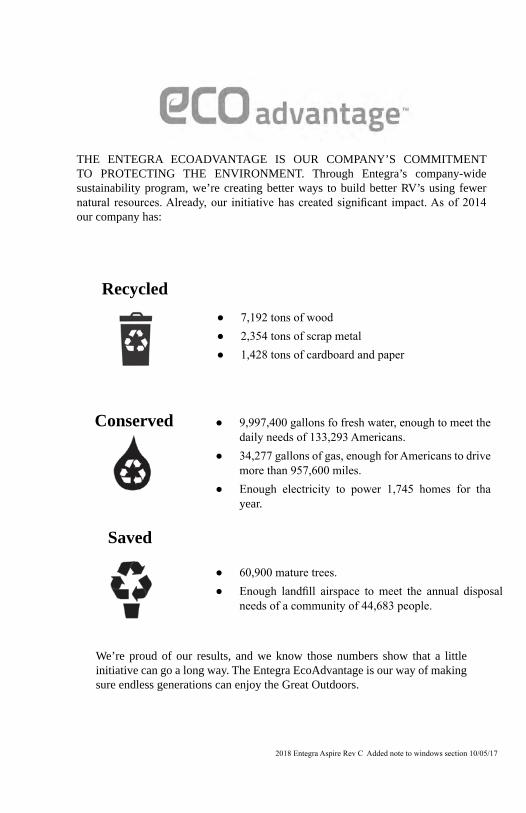
THE ENTEGRA ECOADVANTAGE IS OUR COMPANY’S COMMITMENT TO PROTECTING THE ENVIRONMENT. Through Entegra’s company-wide sustainability program, we’re creating better ways to build better RV’s using fewer natural resources. Already, our initiative has created significant impact. As of 2014 our company has:
Recycled
Conserved
Saved
We’re proud of our results, and we know those numbers show that a little initiative can go a long way. The Entegra EcoAdvantage is our way of making sure endless generations can enjoy the Great Outdoors.
● 7,192 tons of wood ● 2,354 tons of scrap metal ● 1,428 tons of cardboard and paper
● 9,997,400 gallons fo fresh water, enough to meet the daily needs of 133,293 Americans.
● 34,277 gallons of gas, enough for Americans to drive more than 957,600 miles.
● Enough electricity to power 1,745 homes for tha year.
● 60,900 mature trees. ● Enough landfill airspace to meet the annual disposal
needs of a community of 44,683 people.
2018 Entegra Aspire Rev C Added note to windows section 10/05/17

Table of ContentsSection 1: Warranty & Service
Options & Equipment 9Dealer Responsibility 9Customer Relations 9Obtaining Emergency Warranty Repair 10To Contact Us 10
About This Manual 11Warranty Packet 11Chassis Guide 11Safety Alerts 11Reporting Safety Defects 12
To contact NHTSA by phone: 13To Contact NHTSA by mail: 13To contact Transport Canada by mail: 13
Customer Responsibility 13Change Of Address/Ownership 13Suggestions For Obtaining Service 14Obtaining Service For Separately Warranted Items 14Obtaining Service At Our Customer Service Facility 14Parts & Accessories 15Aftermarket Accessories 15Entegra Coach Transfer Limited Warranty Procedure 15
Section 2: Occupant SafetySecondary Means of Escape (Exit Window) 23
Exit Window Label Fire Safety 24Fire Extinguisher 24Smoke Alarm 25Combination Carbon Monoxide /Propane Alarm 27
Carbon monoxide/propane alarmFormaldehyde 30Extended Or Full Time Usage 30Cold Weather Usage 30Condensation 31
Section 3: Pre-Travel InformationVehicle Labels 33
Towing & braking warning labelUpper section Federal OCCC weight labelLower section Federal OCCC weight labelsFederal Certification Label
Loading Your Motorhome 35Trailer Plug 36Weighing Your Motor home 36
7-way trailer plug - Car end, rear viewSection 4: Vehicle Operations
Vehicle Operation 39Braking & Stopping 39Parking Brake 39
Using The Rear Hitch 40Towing and braking label
Step Well & Cover 41Entrance Step 41Entrance Door 42Keyless Entry 43
Table of Contents
Cargo Mode FOB (4 button): 43Standard Mode FOBCargo Mode FOBKeypadWood grain tray
Emergency Override 47Driver & Passenger Seat 47Seat Belts 48Starting & Stopping The Engine 48Instrument Panel 48
Transmission indicator shift panelDash Instrument Panel 49
Left Panel 49Center Panel 49
Driver Side Console Instrument Panel 50Passenger Side Console Instrument Panel 50Passenger Side Console Instrument Panel (front) 51Steering Wheel & Column Controls 51
Tilt & Telescoping 51ICC Flashers 51Wiper Blades 51
Headlight Flash ControlDriver’s Console Control Panel 52
Docking Lights 52Map Lights 52
Driving Lights 52Clearance Light Flash Control
Cruise Control Function 52Hazard-Warning Flasher 52Daytime Running Lights (DRL) 53
Front In-Dash AM/FM/CD/DVD & Navigation System 53Coin Tray And Cup Holders 53Outside Rearview Mirrors 53
Remote Mirror Control/Mirror Heat ControlRear and Side View Cameras 54Total Vision Camera System 55Climate Control System(Dash) 55Campsite Hook-Up 57Chassis Air Bags 57Hydraulic Leveling System 58
Hydraulic Control PanelEmergency Stopping 62Emergency Towing 62Front Axle Tire Alignment 63Wheel Lug Nuts/Wheel Liners 64Tires 65Changing A Tire 67Awnings (if so equipped) 67
Section 5: Slideout SystemsElectric Slide Room(s) 69
Section 6: Electrical SystemThe Electrical System 71In Case Of An Electrical Fire 71Controls and Switches 72
Table of ContentsPower Cut Out Switches 72GFCI Receptacle 72Power Control (Energy Management) System 73Testing The Campsite Power Connection 73Inverter/Charger 75
Vegatouch inverter displayInverter
12-volt DC System 77Inverter Fuse
Batteries 79Battery Disconnect Switch
120-Volt Circuit Breakers 82Approximate Electrical Load Ratings 83120-Volt (50 AMP) AC System (if so equipped) 84Power Cord Reel (If So Equipped) 85Generator 85Starting the Generator 87Generator Slide Tray 88Replacing Light Bulbs 88
Section 7: Fuel SystemDiesel Fuel & Fill 89Exhaust Gas Fumes 90
Section 8: Plumbing SystemPlumbing System 91Monitor Panel 91
Docking Center Monitor PanelFresh Water System 93Universal Docking Center 98Aqua-Hot Heating System 105Outside Shower & Courtesy Light 110Faucets 111Bathroom Shower 111Black/Grey Water System and Tanks 111Black /Gray Tank Drains & Macerator System 113Black Tank Flush (If So Equipped) 115
Tank Flush InletToilet 116
Section 9: Heating & CoolingAir Conditioner/Heat Pump 119
LCD DisplayPower Fan (if so equipped) 122
Wall Switch Operation: 122Fan Information and Operating Guide: 124Adjusting the Thermostat Temperature: 125Insect Screen: 126
Heating System(s) 126Fireplace (If So Equipped) 126
Section 10: AppliancesMicrowave 127Cooking Safety 127Induction Cooktop (If So Equipped) 128Range Hood (If So Equipped) 128Refrigerator 129
Table of Contents
Dishwasher (if so equipped) 130Washer/Dryer (if so equipped) 130Vacuum Systems (If So Equipped) 131
Dryer vent labelSection 11: Electronics
Antenna/Satellite System(s) 133Base with locking button.Push knob in to rotate antennaAntenna Power Supply
Entertainment Center(s) 138Built-in Computer Workstation (If So Equipped) 139Wi-Fi Booster (if so equipped) 139
Section 12: InteriorCleaning The Interior 141Sofa & Dinette 143Pantry or Hutch (If So Equipped) 144Convertible Table (If So Equipped) 144Countertops 147Flooring 148Ceiling Fabric 149Power Window Shades (if so equipped) 149Sleep Number® Mattress (if so equipped) 149Power Bunk Bed (if so equipped) 149Safe (if so equipped) 150Entry Door Overhead Control Panel 151Bathroom Cabinet Control Panel 151
Section 13: ExteriorCleaning The Exterior 153Frame 156Front Axle Tire Alignment 156Mud Flap (If so Equipped) 156Engine & Generator Compartment Access 157Hinges, Locks & Latches (interior & exterior) 157Exterior Roof & Sidewall Vents 157Windows 157Sealants 158
Section 14: Travel/Camping/Storage ChecklistsTravel Checklist 159Motor home Storage 160Quick Start Guide 161
Camp Setup / Tear Down 161Entegra Coach Emergency Contact Information 161Comfort Control Settings 161Entertainment Center Set-Up 162Overall Dimensions 162
Section 15: Additional InformationFeatured Components Quick Reference Chart 163Vehicle Maintenance Record 165

7
WARNING: READ ALL INSTRUCTIONS IN THIS MANUAL AND COMPONENT MANUFACTURER SUPPLIED INFORMATION BEFORE USING YOUR RV.
This manual has been provided by your recreational vehicle manufacturer for the sole purpose of providing instructions concerning the operation and maintenance of this recreational vehicle. Nothing in this manual creates any warranty, either expressed or implied.
The owner’s failure to provide required service and/or maintenance could result in the loss of warranty. Please review the limited warranty and the limited warranties that apply to specific components offered with this vehicle.
Instructions are included in the manual for operating various components which are optional on some RV’s or may not be available on your particular model. “If so equipped” does not indicate or imply that the component(s) or option(s) were at any time available, or can be retrofitted to your model. In addition, the owner should refer to individual manufacturer’s operating instructions contained in the owner’s packet.

8
9
Section 1: Warranty & Service
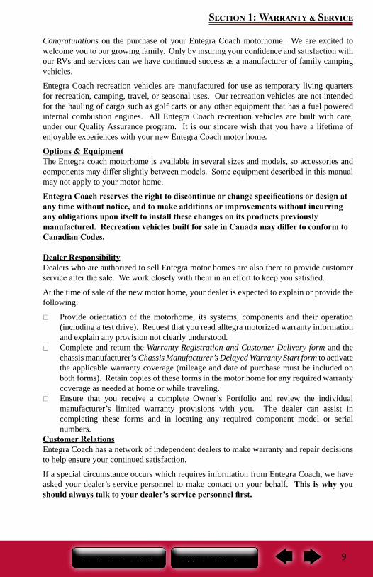
Congratulations on the purchase of your Entegra Coach motorhome. We are excited to welcome you to our growing family. Only by insuring your confidence and satisfaction with our RVs and services can we have continued success as a manufacturer of family camping vehicles.
Entegra Coach recreation vehicles are manufactured for use as temporary living quarters for recreation, camping, travel, or seasonal uses. Our recreation vehicles are not intended for the hauling of cargo such as golf carts or any other equipment that has a fuel powered internal combustion engines. All Entegra Coach recreation vehicles are built with care, under our Quality Assurance program. It is our sincere wish that you have a lifetime of enjoyable experiences with your new Entegra Coach motor home.
Options & EquipmentThe Entegra coach motorhome is available in several sizes and models, so accessories and components may differ slightly between models. Some equipment described in this manual may not apply to your motor home.
Entegra Coach reserves the right to discontinue or change specifications or design at any time without notice, and to make additions or improvements without incurring any obligations upon itself to install these changes on its products previously manufactured. Recreation vehicles built for sale in Canada may differ to conform to Canadian Codes.
Dealer ResponsibilityDealers who are authorized to sell Entegra motor homes are also there to provide customer service after the sale. We work closely with them in an effort to keep you satisfied.
At the time of sale of the new motor home, your dealer is expected to explain or provide the following:
Provide orientation of the motorhome, its systems, components and their operation (including a test drive). Request that you read alltegra motorized warranty information and explain any provision not clearly understood.
Complete and return the Warranty Registration and Customer Delivery form and the chassis manufacturer’s Chassis Manufacturer’s Delayed Warranty Start form to activate the applicable warranty coverage (mileage and date of purchase must be included on both forms). Retain copies of these forms in the motor home for any required warranty coverage as needed at home or while traveling.
Ensure that you receive a complete Owner’s Portfolio and review the individual manufacturer’s limited warranty provisions with you. The dealer can assist in completing these forms and in locating any required component model or serial numbers.
Customer RelationsEntegra Coach has a network of independent dealers to make warranty and repair decisions to help ensure your continued satisfaction.
If a special circumstance occurs which requires information from Entegra Coach, we have asked your dealer’s service personnel to make contact on your behalf. This is why you should always talk to your dealer’s service personnel first.
10
Section 1: Warranty & Service
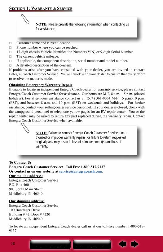
Customer name and current location. Phone number where you can be reached. 17-digit chassis Vehicle Identification Number (VIN) or 9-digit Serial Number. The current vehicle mileage. If applicable, the component description, serial number and model number. A detailed description of the concern.
If problems arise after you have consulted with your dealer, you are invited to contact Entegra Coach Customer Service. We will work with your dealer to ensure that every effort to resolve the matter is made.
Obtaining Emergency Warranty RepairIf unable to locate an independent Entegra Coach dealer for warranty service, please contact Entegra Coach Customer Service for assistance. Our hours are M-F, 8 a.m. – 5 p.m. (closed holidays). For after-hours assistance contact us at: (574) 361-0034 M-F 5 p.m.-10 p.m. (EST), and between 8 a.m. and 10 p.m. (EST) on weekends and holidays. For further assistance, contact your selling dealer service personnel. If your dealer is closed, check with the campground personnel or telephone yellow pages for an RV repair center. You or the repair center may be asked to return any part replaced during the warranty repair. Contact Entegra Coach Customer Service when available.
To Contact UsEntegra Coach Customer Service: Toll Free 1-800-517-9137Or contact us on our website at [email protected] mailing address:Entegra Coach Customer Service P.O. Box 460903 South Main StreetMiddlebury IN 46540
Our shipping address:Entegra Coach Customer Service 100 Bontrager DriveBuilding # 42, Door # 4220Middlebury IN 46540
To locate an independent Entegra Coach dealer call us at our toll-free number 1-800-517-9137.
NOTE: Please provide the following information when contacting us for assistance:
NOTE: Failure to contact Entegra Coach Customer Service, unau-thorized or improper warranty repairs, or failure to return requested original parts may result in loss of reimbursement(s) and loss of warranty.
11
Section 1: Warranty & Service
About This ManualThis manual is a guide to operation of the features, equipment and controls in your recreation vehicle. If you find components vary significantly from what is described, please contact your dealer to ensure you have the correct information. Nothing in this manual creates any warranty, either expressed or implied.
This Owner’s Manual and Warranty Packet are to be considered permanent components of the vehicle. Keep them in your recreation vehicle at all times for personal reference. If the recreation vehicle is sold, they should remain with the vehicle for the next owner. Nothing in this manual creates any warranty, either expressed or implied, nor does it cover every possible detail of equipment, standard or option, installed on or in your recreation vehicle.
Information, illustrations and specifications in this manual reflect the most current available at the time of publication approval, are subject to change and not intended to indicate actual size.
Warranty PacketThere are components that are excluded from the vehicle warranty, or are warranted separately by their own individual manufacturer’s limited warranty. The Warranty Packet contains these component manufacturer supplied manuals or information sheets, warranty cards and/or registrations. Consult this information for questions regarding operating, maintenance, servicing instructions and warranty coverage. It is important you complete and mail warranty cards and registrations within the prescribed time limits to avoid loss of warranty coverage.
Chassis GuideThroughout this manual, frequent reference is made to the vehicle’s Chassis Guide. The Chassis Guide includes the owner’s manual provided by the manufacturer of the chassis on which this motor home is built, warranty cards and/or registrations. It also includes pertinent information regarding the transmission, tires, etc. Consult the Chassis Guide for operating safety, maintenance, servicing instructions and warranty coverage. The Chassis Guide should be considered a permanent component of the vehicle and kept in the motor home at all times for reference.
Safety AlertsThroughout this manual, certain items are labeled NOTE, CAUTION, WARNING, and DANGER. These terms will alert you to precautions that can involve risk to your vehicle or to your personal safety.
Read and follow them carefully. National Safety Associations and organizations require many of the instructions listed. Always use the appropriate safety gear when servicing or maintaining your recreation vehicle. Please call your dealer or our customer service representatives if you are unsure how to proceed.
These signal words indicate precautions and potential situations, which if not avoided, may result in personal injury, property damage, or damage to your recreation vehicle. These precautions are listed in the appropriate areas in this Owner’s Manual, and in the information contained in the Warranty Packet, and on safety labels affixed to your recreation vehicle. Read and follow them carefully.
12
Section 1: Warranty & Service
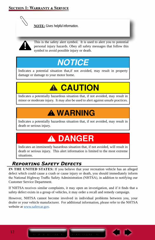
NOTE: Gives helpful information.
This is the safety alert symbol. It is used to alert you to potential personal injury hazards. Obey all safety messages that follow this symbol to avoid possible injury or death.
Indicates a potentially hazardous situation that, if not avoided, may result in death or serious injury.
Indicates an imminently hazardous situation that, if not avoided, will result in death or serious injury. This alert information is limited to the most extreme situations.
Indicates a potentially hazardous situation that, if not avoided, may result in minor or moderate injury. It may also be used to alert against unsafe practices.
Indicates a potential situation that,if not avoided, may result in property damage or damage to your motor home.
Reporting Safety DefectsIN THE UNITED STATES: If you believe that your recreation vehicle has an alleged defect which could cause a crash or cause injury or death, you should immediately inform the National Highway Traffic Safety Administration (NHTSA), in addition to notifying our Customer Service Department.
If NHTSA receives similar complaints, it may open an investigation, and if it finds that a safety defect exists in a group of vehicles, it may order a recall and remedy campaign.
However, NHTSA cannot become involved in individual problems between you, your dealer or your vehicle manufacturer. For additional information, please refer to the NHTSA website at www.safercar.gov.
13
Section 1: Warranty & Service
To contact NHTSA by phone:Call the Department of Transportation (DOT) Vehicle Safety Hotline at 1-888-327-4236, and a NHTSA representative will record your complaint information (TTY: 1-800-424-9153 or 1-202-484-5238).
To Contact NHTSA by mail:Office of Defects Investigations/CRDNVS-2161200 New Jersey Ave SEWashington, DC 20590In Canada: If you believe your vehicle has an alleged safety defect, you should contact Transport Canada and our Customer Service Department immediately. Transport Canada prefers to be called instead of posted mail or email as it enables their investigators to confirm that your information is correct, and to answer your questions accurately. For additional information, please refer to the Transport Canada website at www.tc.gc.ca .
To contact Transport Canada by phone:Call 1-800-333-0510 (or 1-613-993-9851 if you are calling from the Ottawa region) and ask to speak to a defect investigator.
To contact Transport Canada by mail:Road Safety and Motor VehicleRegulation DirectorateTransport CanadaTower C, Place de Ville330 Sparks StreetOttawa, Ontario K1A 0N5
Customer ResponsibilityIt is important you read and understand all instructions and precautions before operating the recreation vehicle. Even if you are an experienced RV’er we encourage you to thoroughly read this Owner’s Manual, as well as the information contained in your Warranty Packet and Chassis Guide (motorized only).
As technology advances, new improvements enter the RV industry every day, and each RV manufacturer has its own unique manufacturing process.
Familiarize yourself with the Limited Warranty applicable to your recreation vehicle. There are components that are excluded or warranted separately by their individual manufacturer’s limited warranty (refer to the Warranty Packet or Chassis Guide if applicable).
As the new owner of the recreation vehicle, you are responsible for regular and proper maintenance performed in accordance with this manual and the OEM manuals. Regular and proper maintenance will help prevent conditions arising from neglect that are not covered by the limited warranty. It is your responsibility and obligation to return your vehicle to your dealer for repairs and service.
Change Of Address/OwnershipPlease notify our Customer Service Department as soon as possible of a change of address by writing or calling us. For notification of a change of ownership, please fill out the appropriate form located in this manual and mail it to Customer Service along with documentation showing proof of ownership. Please include your current vehicle mileage (motorized only).
14
Section 1: Warranty & Service
Suggestions For Obtaining ServiceTo help ensure your dealer provides the level of service you expect, here are some suggestions we would like to make:
Contact your dealer at once… Do not wait until you are ready to use your RV. Your dealer may not be able to service it immediately and/or the repair may require parts be ordered. The dealer’s service department is busiest on Mondays, Fridays and before the holidays.
Prepare for the appointment… If you are having warranty work performed, be sure to have the right papers with you. Take your warranty folder and have your vehicle information available. All work to be performed may not be covered by the warranty. Discuss additional charges with the service personnel.
Prepare a list… Provide your dealer with a written list of specific repairs needed. It is important that you provide any vehicle repair history to the dealer’s service personnel.
Keep a maintenance log of your vehicle’s service history. This can often provide a clue to the current issue.
Be reasonable with your requests… If you leave a list with several items and you need your vehicle returned back by a specific time, discuss the situation with the dealer’s service personnel and list your items in order of priority. This may include making a second appointment for work not completed or parts that the dealer may need to order.
Don’t expect to look over the technician’s shoulder… Please don’t be offended if you are told you cannot watch the work being done. Some insurance requirements forbid admission of customers to the service area.
Inspect the work performed… Finally, check out the service or repair job when you pick up your vehicle. Notify the dealer’s service personnel immediately of any dissatisfaction. If you cannot return the vehicle immediately for repair, make an appointment as soon as possible.
Please be aware that all service shops require notification of any issues with their repairs within a specified time limit. Make sure you are familiar with their repair policies.
Obtaining Service For Separately Warranted Items
Your selling dealer is responsible for servicing your recreational vehicle before delivery, and has an interest in your continued satisfaction. We recommend your dealer perform all inspection, warranty and maintenance services. Some dealers may be authorized service centers for those OEMs whose products are warranted separately and excluded from the Limited Warranty.
Obtaining Service At Our Customer Service Facility
Should your recreation vehicle be in need of service, and your dealer recommends that the repairs be made at our Customer Service facility, your recreation vehicle may be returned to us with the following guidelines*:
You or your dealer must make a confirmed appointment 60 days prior to dropping off the recreation vehicle at our Customer Service facility.
The holding tanks must be emptied and rinsed. We have a dumping station available for customer use.
15
Section 1: Warranty & Service
Parts & AccessoriesContact your authorized dealer for assistance in obtaining replacement parts or accessories. We do not sell direct to retail or non-authorized dealers. If the original part is no longer available, we will make every effort to provide an appropriate substitute.
The propane system (if so equipped) and all electrical systems must be shut down and turned off. We are not responsible for discharged batteries or propane tanks.
During the appropriate season, please ensure the RV has been winterized. Unless prior approval has been obtained from our Customer Service facility, all personal
items must be removed from the area where you are requesting service repair and the refrigerator emptied. We are not responsible for loss of food items.
All transportation costs are the responsibility of the owner. You may need to arrange for alternative accommodations for some types of repairs. Please be prepared accordingly.
*Our Customer Service facility occasionally utilizes local independent repair facilities. Your vehicle may be referred to or repaired by one of these local repair facilities.
Aftermarket Accessories
Installation of aftermarket accessory(s) may affect the Limited Warranty applicable to your Recreational vehicle, damage your RV and/or cause a failure. Your RV manufacturer accepts no responsibility for results of work performed by unauthorized technicians.
If you wish to make changes, consult an authorized dealer or your RV manufacturer beforeother resources. They may be able to refer you to a specialist.
Do not add any type of rack or frame to any motor home frame or chassis part. The alteration to the length and/or weight distribution may result in unstable handling, be a safety hazard, or could damage the motor home components.
Entegra Coach Transfer Limited Warranty Procedure
The Entegra Coach “Motorized Transferable Limited Warranty” is transferable to a second owner (certain restrictions apply*). Please contact an independent Entegra Coach dealership for assistance to see if you are eligible.
*To qualify for coverage, your motor home must be eligible as set forth under the terms of the applicable “Motorized Transferable Limited Warranty” offered by Entegra Coach.
16
Section 1: Warranty & Service
ENTEGRA COACH MOTORIZED LIMITED WARRANTYWHAT AND WHO IS COVERED: This limited warranty covers: (i) the motorhome when it is used only for its intended purpose of recreational travel and camping; (ii) only the first retail purchaser and any second retail owner; (iii) only those portions of the Motorhome not excluded under the section “What is Not Covered”; (iv) the motorhome only when sold by an authorized dealership; and, (v) only defects in workmanship performed and/or materials used to assemble those portions of the Motorhome not excluded under the section “what is Not Covered”. The Limited Warranty is not transferable beyond the second retail owner. The second retail owner’s warranty coverage period shall be the unexpired balance of the warranty coverage period the first retail owner received. The second retail owner should complete and submit a Product Registration that is within the Owner’s Manual.
COVERAGE TIME: The duration of this warranty is 2 years after the first retail owner takes delivery of the Motorhome from an authorized dealer OR 24,000 miles of use, whichever occurs first. If the dealer places the Motorhome in service before retail sale, the coverage period is 2 years after the dealer first placed the Entegra in service OR 24,000 miles of use, whichever occurs first, ANY ACTION FOR BREACH OF THIS LIMITED WARRANTY OR FOR ANY IMPLIED WARRANTY MUST BE COMMENCED NO MORE THAN 26 MONTHS AFTER THE BREACH. If the Motorhome is not of the current or prior model year when the first retail owner takes delivery, the limited warranty ends 90 days after the first retail owner takes delivery of the Motorhome OR after the odometer reaches 5,000 miles, whichever occurs first. ANY ACTION FOR BREACH OF THIS REDUCED LIMITED WARRANTY OR FOR ANY IMPLIED WARRANTY MUST BE COMMENCED NO MORE THAN 15 MONTHS AFTER THE BREACH. Unless prohibited by state or provincial law, repairs do not extend the time when you must commence an action for breach of warranty and shall not extend the warranty coverage period. This reduction in time may not apply to you because some states and provinces do not allow the reduction of the time to commence an action for breach of warranty. Any performance of repairs after the warranty coverage ends and any performance of repairs to those portions of your motorhome excluded from coverage are “good will” repairs. You should expect the need for warranty repairs. Entegra may use new and/or remanufactured parts and/or components to complete a repair. Warranty repairs may have been performed to defects with and/or damage to interior or exterior surfaces, trim, upholstery and other appearance items at the factory during assembly OR at the selling dealership after delivery of the Motorhome to your selling dealer - Repairs to defects and damage are performed at the factory or by the selling dealer during the inspection process. If you discover a defect or damage to the motorhome when you take delivery of your motorhome, you MUST notify your dealer OR Entegra within 10 days of the date of purchase to have defect or damage repaired at no cost to you. Minor adjustments will be performed, free of charge, by the dealer within 90 days of your purchase; thereafter, such adjustments are your exclusive responsibility as normal maintenance.
REPAIR REMEDY: Entegra’s sole and exclusive obligation is to repair any covered defect discovered within the warranty coverage period provided: (1) you notify Entegra or an authorized dealer within 10 days of your discovery of a defect; AND (2) you deliver the Motorhome to Entegra OR an authorized dealership at your cost and expense.
BACK-UP REMEDY: If the primary repair remedy fails to successfully cure any defect after a reasonable number of repair attempts, your sole and exclusive remedy shall be to have Entegra pay an independent service shop of your choice to perform repairs to the
17
Section 1: Warranty & Service
defect OR have Entegra pay diminished value damages if the defect is incurable. You must exhaust both the repair remedy and the back-up remedy AND these remedies must fail to fulfill their essential purpose before you can seek any other remedies. THIS LIMITED WARRANTY IS NOT A WARRANTY THAT PROMISES OR EXTENDS TO FUTURE PERFORMANCE BECAUSE IT DOES NOT MAKE A REPRESENTATION ON HOW YOUR MOTORHOME WILL PERFORM IN THE FUTURE BUT REPRESENTS ONLY WHAT THE REMEDY WILL BE IF A DEFECT EXISTS.
LIMITATION AND DISCLAIMER OF IMPIED WARRANTIES: THE DURATION OF ANY IMPLIED WARRANTY IS LIMITED TO: (i) THE DURATION OF THIS LIMITED WARRANTY; (ii) THE SCOPE OF COVERAGE THIS LIMITED WARRANTY PROVIDES; (iii) DEFECTS EXISTING AT THE TIME OF SALE THAT MANIFESTED THEMSELVES AND SURFACED DURING THE IMPLIED WARRANTY COVERAGE PERIOD; AND (IV) DEFECTS DISCOVERED AND REPORTED WITHIN THE DURATION OF THE IMPLIED WARRANTY. THERE ARE NO EXPRESS WARRANTIES OR ANY IMPLIED WARRANTIES ON THOSE PORTIONS OF THE MOTORHOME EXCLUDED FROM COVERAGE. NOTWITHSTANDING THE ABOVE PROVISIONS, ENTEGRA EXPRESSLY DISCLAIMS AND EXCLUDES ANY AND ALL IMPLIED WARRANTIES AND CONDITIONS, STATUTORY OR OTHERWISE, WHEN THE MOTORHOME IS USED FOR COMMERICAL, RENTAL OR BUSINESS USE AND WHEN THE ENTEGRA IS SOLD IN CANADA. There is no warranty of any nature made by Entegra beyond that contained in this Limited Warranty. No person has authority to enlarge, amend or modify this Limited Warranty. The dealer is NOT Entegra’s agent. Entegra is not responsible for any undertaking, representation or warranty made by any dealer or others beyond those expressly set forth within this Limited Warranty. Some states and provinces do not allow limitations on how long an implied warranty lasts, so the above limitation may not apply to you.
DISCLAIMER OF CONSEQUENTIAL AND INCIDENTAL DAMAGES: THE FIRST RETAIL BUYER AND ANY SUBSEQUENT OWNER, ALONG WITH ANY PERSON WHO IS AN INTENDED OR UNINTENDED USER OR BENEFICIARY OF THE MOTORHOME, ARE NOT ENTITLED TO RECOVER ANY CONSEQUENTIAL OR INCIDENTAL DAMAGES CAUSED BY A DEFECT IN THE MOTORHOME. BY WAY OF EXAMPLE, CONSEQUENTIAL DAMAGES INCLUDE FUEL AND TRANSPORTATION EXPENSES TO DELIVER THE MOTORHOME TO A SERVICING DEALER, HOTEL ROOMS, LOST WAGES AND MOISTURE DAMAGE SUCH AS MOLD AND MILDEW AS WELL AS RUST AND CORROSION. THE EXCLUSION OF CONSEQUENTIAL AND INCIDENTAL DAMAGES ARE NOT DEPENDENT UPON WARRANTY REMEDIES SUCCESSSFULLY CURING ANY DEFECT; THE EXCLUSION OF CONSEQUENTIAL AND INCIDENTAL DAMAGES SHALL SURVIVE ANY FAILURE OF THE LIMITED WARRANTY REMEDIES FULFILLING THEIR PURPOSE. Some states do not allow the exclusion or limitation of consequential or incidental damages, so the above exclusions may not apply to you.
HOW TO GET SERVICE: To obtain warranty service the owner must: (i) Notify Entegra or an authorized Entegra dealer, within the applicable warranty coverage period designated above, that you are making a warranty claim under; (ii) Provide the notification mentioned in (1), above, within ten (10) days of the discovery of a defect in material or workmanship; and (iii) Promptly schedule an appointment with and take the Motorhome to Entegra or an independent, authorized dealer. If you need assistance, you may contact Entegra, at 903
18
Section 1: Warranty & Service
South Main Street, P. O. Box 460, Middlebury, Indiana 46540, Attn: Customer Service, (800) 517-9137.
WHAT IS NOT COVERED: Equipment and appliances installed after the Motorhome is assembled by Entegra; Motorhomes used for any rental, business and commercial purpose - If the Motorhome owner files a tax form claiming a business or commercial tax benefit related to the Motorhome, or if the RV is purchased, registered or titled in a business name is shall be irrefutable that the Motorhome has been used for rental, commercial or business purposes; any Motorhome sold or used outside of the United States, U.S. Territories or Canada; any Motorhome not used solely for recreational travel and camping; any Motorhome purchased through auction or wholesale; any Motorhome purchased from a dealer that is not an authorized dealer; normal wear, tear or usage, such as tears, punctures, soiling, mildew, rust, fading, or discoloration of exterior plastic or fiberglass, or soft goods, such as upholstery, drapes, carpet, vinyl, screens, cushions, mattresses and fabrics; the effects of condensation or moisture from condensation inside the RV; mold or any damage caused by mold to the interior or exterior; imperfections that do not affect the use of the Motorhome for its intended purpose of recreational use; items working as designed but that you are unhappy with; damage caused by misuse, mishandling, neglect, abuse, failure to maintain the Motorhome in accordance with the owner’s manual, or failure to perform other routine maintenance such as inspections, lubricating, adjustments, tightening of screws and fittings, tightening of lug nuts, sealing, rotating tires; damage caused by accident, whether or not foreseeable; damage caused by weather or corrosion due to the environment; damage caused by theft, vandalism or fire; damage caused by tire wear or tire failure; defacing, scratches, dents, chips on any surface or fabric of the Motorhome; damage caused by off road use, overloading the Motorhome or any of its components or parts; wheel alignment or adjustments to axles caused by improper maintenance, loading or damage from road hazards, including off road travel; wheel damage or balancing. Also, this limited warranty does not cover any material, component, system or part that is warranted by another entity, including, by way of example, the: automotive chassis, (which includes the power train, steering, handling, braking, wheel balance, muffler, tires, tubes, batteries and gauges), generator, hydraulic jacks, inverter, converter, microwave, television, DVD/CD player, radio, speakers, television, refrigerator, range, water heater, water pump, stove, carbon monoxide detector, smoke detector, propane detector, furnace or any air conditioner. The written warranty provided by the manufacturer of the component part is the direct and exclusive responsibility of that manufacturer).
EVENTS DISCHARGING ENTEGRA FROM OBLIGATION UNDER WARRANTY: The following, by way of example, discharge Entegra from any express or implied warranty obligation to repair or replace any defect: any rental, business or commercial use or purchase of the Motorhome; any Motorhome purchased or sold outside of, or used outside of, the United States, U.S. Territories or Canada; any Motorhome purchased through an auction or wholesale or by a non-authorized dealer; owner neglect; failure to provide routine maintenance; alteration; off road use; collision or accident, whether or not foreseeable; acts of weather; damage or corrosion caused by the environment, theft, vandalism, fire, explosions, or overloading.
LEGAL REMEDIES: EXCLUSIVE JURISDICTION FOR DECIDING LEGAL DISPUTES RELATING TO ALLEGED BREACH OF WARRANTY, OR ANY REPRESENTATIONS OF ANY NATURE, MUST BE FILED IN THE COURTS WITHIN THE STATE OF MANUFACTURE, WHICH IS INDIANA. THIS LIMITED WARRANTY SHALL BE INTERPRETED AND CONSTRUED IN ACCORDANCE WITH THE LAWS
19
Section 1: Warranty & Service
OF THE STATE OF INDIANA. ALL CLAIMS, CONTROVERSIES AND CAUSES OF ACTION ARISING OUT OF OR RELATING TO THIS LIMITED WARRANTY, WHETHER SOUNDING CONTRACT, TORT OR STATUTE, SHALL BE GOVERNED BY THE LAWS OF THE STATE OF INDIANA, INCLUDING ITS STATUTE OF LIMITATIONS, WITHOUT GIVING EFFECT TO ANY CONFLICT OF LAW RULE THAT WOULD RESULT IN THE APPLICATION OF THE LAWS OF A DIFFERENT JURISDICTION. THIS WARRANTY GIVES YOU SPECIFIC LEGAL RIGHTS. YOU MAY ALSO HAVE OTHER RIGHTS, WHICH VARY FROM STATE TO STATE AND PROVINCE TO PROVINCE. ALL ACTIONS OF ANY KIND RELATING TO THE MOTORHOME SHALL BE DECIDED BY A JUDGE RATHER THAN BY A JURY.
WARRANTY REGISTRATIONS: Your warranty registrations should be completed and delivered to the manufacturers of component parts. The selling dealership will assist you in completing and filling out the Entegra product warranty registration. Upon receipt of the Warranty Registration by Entegra, your Warranty will be registered. The failure to submit this warranty registration to Entegra will not affect your rights under this limited warranty as long as you can present proof of purchase, however, it can cause delays in obtaining the remedies offered by this limited warranty, and it may adversely affect any servicing facility’s ability to provide proper repairs and/or part replacement.
CARE AND MAINTENANCE: It is the Owner’s responsibility to perform proper care and maintenance of the Motorhome and to assure correct load distribution. For details regarding this, please see your owner’s manuals. Please review all manuals and contact your selling dealership, Entegra or supplier of the component part if you have questions. THIS WARRANTY GIVES YOU SPECIFIC LEGAL RIGHTS; YOU MAY HAVE OTHER RIGHTS THAT VARY FROM STATE TO STATE.
ENTEGRA COACH 903 S. Main Street * P. O. Box 460 *
Middlebury, IN 46540 Telephone: 800-517-9137
ENTEGRA COACH MOTORIZED STRUCTURAL LIMITED WARRANTY
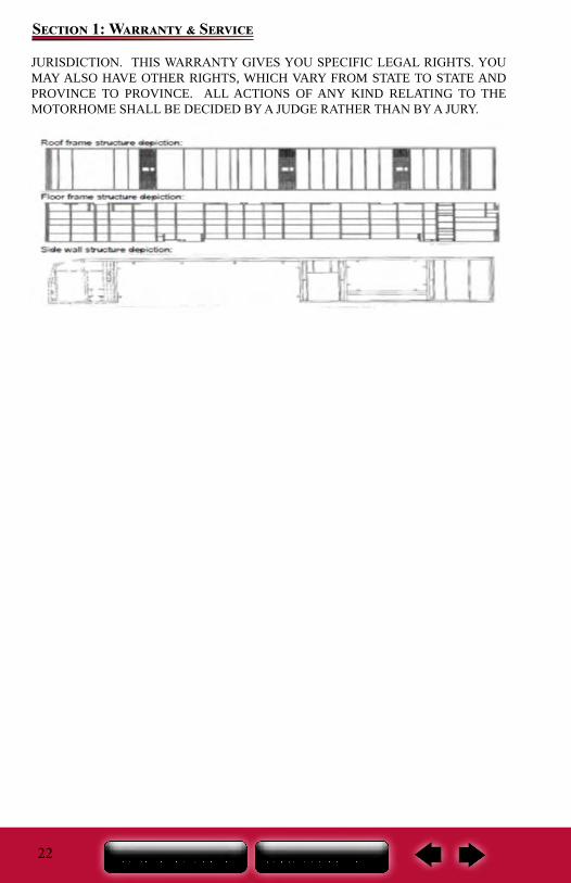
WHAT AND WHO IS COVERED: This limited warranty covers: (i) the structure of the motorhome when it is used only for its intended purpose of recreational travel and camping; (ii) only the first retail purchaser and any second retail owner of the Motorhome; (iii) only defects in workmanship and/or materials used to assemble the structure of the Motorhome; (iii) the structure of the motorhome only when the Motorhome is sold by an authorized dealership; and, (iv) only the steel or aluminum frame structure for the sidewalls (excluding slide outs), roof and rear and front walls. The Structural Limited Warranty is not transferable beyond the second retail owner. The second retail owner’s warranty coverage period shall be the unexpired balance of the warranty coverage period the first retail owner received. The second retail owner should complete and submit a Product Registration that is within the Owner’s Manual.
COVERAGE TIME: The duration of this Structural limited warranty is 5 years after the first retail owner takes delivery of the Motorhome from an authorized dealer. If the dealer places the Motorhome in service before retail sale, the coverage period is 5 years after the
20
Section 1: Warranty & Service
dealer first placed the Entegra in service. Unless prohibited by state or provincial law, repairs do not extend the time when you must commence an action for breach of warranty and shall not extend the warranty coverage period. This reduction in time may not apply to you because some states and provinces do not allow the reduction of the time to commence an action for breach of warranty. Any performance of repairs after the warranty coverage ends and any performance of repairs to those portions of your motorhome excluded from coverage are “good will” repairs. You should expect the need for warranty repairs. Entegra may use new and/or remanufactured parts and/or components to complete a repair.
REPAIR REMEDY: Entegra’s sole and exclusive obligation is to repair any covered defect discovered within the warranty coverage period provided: (1) you notify Entegra or an authorized dealer within 10 days of your discovery of a defect; AND (2) you deliver the Motorhome to Entegra OR an authorized dealership at your cost and expense
BACK-UP REMEDY: If the primary repair remedy fails to successfully cure any defect after a reasonable number of repair attempts, your sole and exclusive remedy shall be to have Entegra pay an independent service shop of your choice to perform repairs to the defect OR have Entegra pay diminished value damages if the defect is incurable. You must exhaust both the repair remedy and the back-up remedy AND these remedies must fail to fulfill their essential purpose before you can seek any other remedies. THIS LIMITED WARRANTY IS NOT A WARRANTY THAT PROMISES OR EXTENDS TO FUTURE PERFORMANCE BECAUSE IT DOES NOT MAKE A REPRESENTATION ON HOW YOUR MOTORHOME WILL PERFORM IN THE FUTURE BUT REPRESENTS ONLY WHAT THE REMEDY WILL BE IF A DEFECT EXISTS.
LIMITATION AND DISCLAIMER OF IMPIED WARRANTIES: ANY IMPLIED WARRANTY IS LIMITED TO: (i) THE SCOPE OF COVERAGE THIS LIMITED WARRANTY PROVIDES; (ii) DEFECTS EXISTING AT THE TIME OF SALE THAT MANIFESTED THEMSELVES AND SURFACED DURING THE IMPLIED WARRANTY COVERAGE PERIOD; AND (ii) DEFECTS DISCOVERED AND REPORTED WITHIN THE DURATION OF THE IMPLIED WARRANTY. THERE ARE NO EXPRESS WARRANTIES OR ANY IMPLIED WARRANTIES ON THOSE PORTIONS OF THE MOTORHOME EXCLUDED FROM COVERAGE. NOTWITHSTANDING THE ABOVE PROVISIONS, ENTEGRA EXPRESSLY DISCLAIMS AND EXCLUDES ANY AND ALL IMPLIED WARRANTIES AND CONDITIONS, STATUTORY OR OTHERWISE, WHEN THE MOTORHOME IS USED FOR COMMERICAL, RENTAL OR BUSINESS USE AND WHEN THE ENTEGRA IS SOLD IN CANADA. There is no warranty of any nature made by Entegra beyond that contained in this Limited Warranty. No person has authority to enlarge, amend or modify this Limited Warranty. The dealer is NOT Entegra’s agent. Entegra is not responsible for any undertaking, representation or warranty made by any dealer or others beyond those expressly set forth within this Limited Warranty. Some states and provinces do not allow limitations on how long an implied warranty lasts, so the above limitation may not apply to you.
DISCLAIMER OF CONSEQUENTIAL AND INCIDENTAL DAMAGES: THE FIRST RETAIL BUYER AND ANY SUBSEQUENT OWNER, ALONG WITH ANY PERSON WHO IS AN INTENDED OR UNINTENDED USER OR BENEFICIARY OF THE MOTORHOME, ARE NOT ENTITLED TO RECOVER ANY CONSEQUENTIAL OR INCIDENTAL DAMAGES CAUSED BY A DEFECT IN THE MOTORHOME.
21
Section 1: Warranty & Service
BY WAY OF EXAMPLE, CONSEQUENTIAL DAMAGES INCLUDE FUEL AND TRANSPORTATION EXPENSES TO DELIVER THE MOTORHOME TO A SERVICING DEALER, HOTEL ROOMS AND LOST WAGES. THE EXCLUSION OF CONSEQUENTIAL AND INCIDENTAL DAMAGES ARE NOT DEPENDENT UPON WARRANTY REMEDIES SUCCESSSFULLY CURING ANY DEFECT; THE EXCLUSION OF CONSEQUENTIAL AND INCIDENTAL DAMAGES SHALL SURVIVE ANY FAILURE OF THE LIMITED WARRANTY REMEDIES FULFILLING THEIR PURPOSE. Some states do not allow the exclusion or limitation of consequential or incidental damages, so the above exclusions may not apply to you.
HOW TO GET SERVICE: To obtain warranty service the owner must: (i) Notify Entegra or an authorized Entegra dealer, within the applicable warranty coverage period designated above, that you are making a warranty claim under; (ii) Provide the notification mentioned in (1), above, within ten (10) days of the discovery of a defect in material or workmanship; and (iii) Promptly schedule an appointment with and take the Motorhome to Entegra or an independent, authorized dealer. If you need assistance, you may contact Entegra, at 903 South Main Street, P. O. Box 460, Middlebury, Indiana 46540, Attn: Customer Service, (800) 517-9137.
WHAT IS NOT COVERED: Motorhomes used for any rental, business and commercial purpose - If the Motorhome owner files a tax form claiming a business or commercial tax benefit related to the Motorhome, or if the RV is purchased, registered or titled in a business name is shall be irrefutable that the Motorhome has been used for rental, commercial or business purposes; any Motorhome sold or used outside of the United States, U.S. Territories or Canada; any Motorhome not used solely for recreational travel and camping; any Motorhome purchased through auction or wholesale; any Motorhome purchased from a dealer that is not an authorized dealer; damage caused by weather or corrosion due to the environment; damage caused by theft, vandalism or fire; damage caused by off road use; and, damage caused by overloading the Motorhome.
EVENTS DISCHARGING ENTEGRA FROM OBLIGATION UNDER WARRANTY: The following, by way of example, discharge Entegra from any express or implied warranty obligation to repair or replace any defect: any rental, business or commercial use or purchase of the Motorhome; any Motorhome purchased or sold outside of, or used outside of, the United States, U.S. Territories or Canada; any Motorhome purchased through an auction or wholesale or by a non-authorized dealer; owner neglect; failure to provide routine maintenance; alteration; off road use; collision or accident, whether or not foreseeable; acts of weather; damage or corrosion caused by the environment, theft, vandalism, fire, explosions, or overloading.
LEGAL REMEDIES: EXCLUSIVE JURISDICTION FOR DECIDING LEGAL DISPUTES RELATING TO ALLEGED BREACH OF WARRANTY, OR ANY REPRESENTATIONS OF ANY NATURE, MUST BE FILED IN THE COURTS WITHIN THE STATE OF MANUFACTURE, WHICH IS INDIANA. THIS LIMITED WARRANTY SHALL BE INTERPRETED AND CONSTRUED IN ACCORDANCE WITH THE LAWS OF THE STATE OF INDIANA. ALL CLAIMS, CONTROVERSIES AND CAUSES OF ACTION ARISING OUT OF OR RELATING TO THIS LIMITED WARRANTY, WHETHER SOUNDING CONTRACT, TORT OR STATUTE, SHALL BE GOVERNED BY THE LAWS OF THE STATE OF INDIANA, INCLUDING ITS STATUTE OF LIMITATIONS, WITHOUT GIVING EFFECT TO ANY CONFLICT OF LAW RULE THAT WOULD RESULT IN THE APPLICATION OF THE LAWS OF A DIFFERENT
22
Section 1: Warranty & Service
JURISDICTION. THIS WARRANTY GIVES YOU SPECIFIC LEGAL RIGHTS. YOU MAY ALSO HAVE OTHER RIGHTS, WHICH VARY FROM STATE TO STATE AND PROVINCE TO PROVINCE. ALL ACTIONS OF ANY KIND RELATING TO THE MOTORHOME SHALL BE DECIDED BY A JUDGE RATHER THAN BY A JURY.
23
Section 2: Occupant Safety
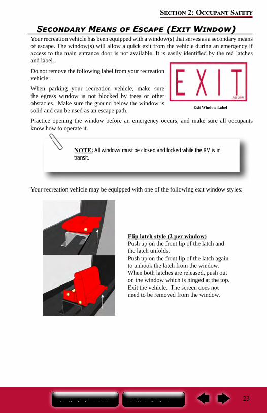
Exit Window Label
Secondary Means of Escape (Exit Window)Your recreation vehicle has been equipped with a window(s) that serves as a secondary means of escape. The window(s) will allow a quick exit from the vehicle during an emergency if access to the main entrance door is not available. It is easily identified by the red latches and label.
Do not remove the following label from your recreation vehicle:
When parking your recreation vehicle, make sure the egress window is not blocked by trees or other obstacles. Make sure the ground below the window is solid and can be used as an escape path.
Practice opening the window before an emergency occurs, and make sure all occupants know how to operate it.
Your recreation vehicle may be equipped with one of the following exit window styles:
Flip latch style (2 per window) Push up on the front lip of the latch and the latch unfolds. Push up on the front lip of the latch again to unhook the latch from the window. When both latches are released, push out on the window which is hinged at the top. Exit the vehicle. The screen does not need to be removed from the window.
NOTE: All windows must be closed and locked while the RV is in transit.
24
Section 2: Occupant Safety
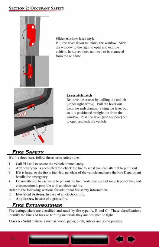
Slider window latch stylePull the lever down to unlock the window. Slidethe window to the right to open and exit the vehicle. he screen does not need to be removedfrom the window.
Lever style latch Remove the screen by pulling the red tab (upper right arrow). Pull the lever out from the sash clamps. Swing the lever out so it is positioned straight out from the window. Push the lever (and window) out to open and exit the vehicle.
Fire SafetyIf a fire does start, follow these basic safety rules:
1. Call 911 and evacuate the vehicle immediately.2. After everyone is accounted for, check the fire to see if you can attempt to put it out. 3. If it is large, or the fire is fuel-fed, get clear of the vehicle and have the Fire Department
handle the emergency.4. Do not attempt to use water to put out the fire. Water can spread some types of fire, and
electrocution is possible with an electrical fire.Refer to the following sections for additional fire safety information.
Electrical Systems, In case of an electrical fire. Appliances, In case of a grease fire.
Fire ExtinguisherFire extinguishers are classified and rated by fire type, A, B and C. These classifications identify the kinds of fires or burning materials they are designed to fight.
Class A - Solid materials such as wood, paper, cloth, rubber and some plastics.
25
Section 2: Occupant Safety
Class B - Liquids such as grease, cooking oils, gasoline, kerosene or other flammable liquids.
Class C - Electrical such as electrical wires or other live electrical equipment.
A dry chemical fire extinguisher has been installed by the entrance door. It is suitable for extinguishing small fires of the Class B or C type only.
We suggest you become thoroughly familiar with the operating instructions displayed on the side of the fire extinguisher.
Inspection and maintenanceRead and follow all instructions on the label and user’s manual provided by the fire extinguisher manufacturer.
Inspect the extinguisher at least once a week (more frequently if it is exposed to weather or possible tampering). This should also be done before beginning a vacation or during an extended trip.
NOTE: For information on how to use your fire extinguisher, refer to the fire extinguisher user’s manual
Do not check the pressure, test or practice using the fire extinguisher by squeezing the trigger, even briefly. The fire extinguisher is not rechargeable or refillable. Once used, it will gradually lose pressure and will not be fully charged for use in an emergency.
Do not turn the electrical power back on or plug in any appliances after the use of a fire extinguisher. Please refer to the fire extinguisher’s user manual for further instructions on maintenance and clean up.
Smoke AlarmThe smoke alarm will only work properly if it is operational and maintained. They have a limited life and will wear out over time. Immediately replace the detector if it is not working properly, if it displays any type of problem, or within five years of use. Be sure to read, understand and follow the information provided by the smoke alarm manufacturer, including information on the limited life of smoke alarms.
Be aware the smoke alarm is not fool proof and cannot detect fires if smoke does not reach it. Anything preventing smoke from reaching the alarm may delay or prevent an alarm.
26
Section 2: Occupant Safety
Though the alarm horn in this detector meets or exceeds current UL standards, it may not be heard for reasons that include (but not limited to): a closed or partially closed door, other noise from electronics, appliances or traffic.
The smoke alarm is operational once the battery is correctly installed. It will not function if the battery is missing, disconnected, dead, the wrong type or not installed correctly. It requires one standard 9V battery. Refer to the user’s guide, for correct battery and installation information,
The LED light will indicate the battery is functioning properly. When the production of combustion is sensed, the smoke detector sounds a loud alarm that continues until the air is cleared. The LED light will also give a visual indication of a sounding alarm.
When the battery becomes weak, the alarm will “beep” about once a minute indicating a low battery. This warning should last for 30 days. You MUST replace the battery once the alarms low battery warning (beep) starts to assure continued protection.
When the battery is removed from the alarm, the battery flag will pop up; the alarm cannot be installed to the mounting bracket without a battery.
To test, stand at arm’s length from the smoke alarm as the alarm horn is loud and may be harmful to your hearing. The test button will accurately test all functions. Never use an open flame to test the smoke alarm.
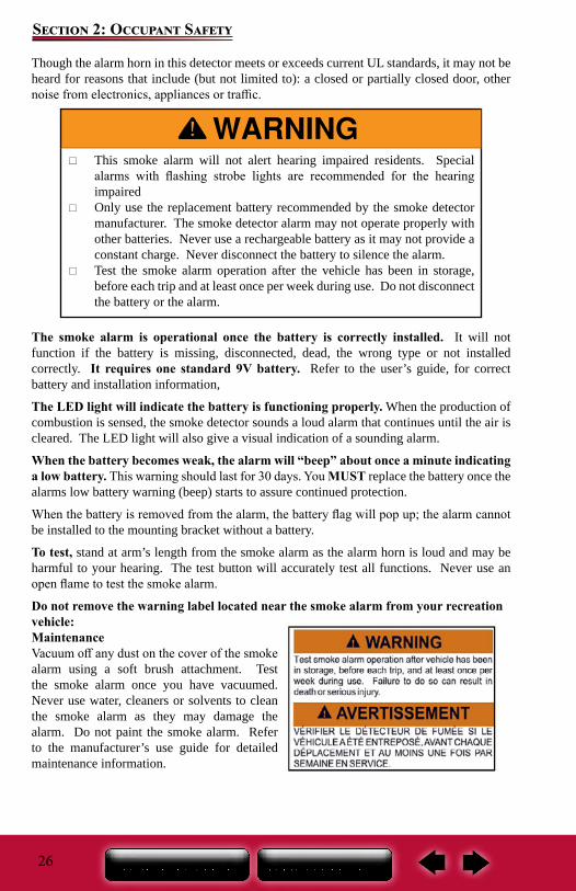
Do not remove the warning label located near the smoke alarm from your recreation vehicle: MaintenanceVacuum off any dust on the cover of the smoke alarm using a soft brush attachment. Test the smoke alarm once you have vacuumed. Never use water, cleaners or solvents to clean the smoke alarm as they may damage the alarm. Do not paint the smoke alarm. Refer to the manufacturer’s use guide for detailed maintenance information.
This smoke alarm will not alert hearing impaired residents. Special alarms with flashing strobe lights are recommended for the hearing impaired
Only use the replacement battery recommended by the smoke detector manufacturer. The smoke detector alarm may not operate properly with other batteries. Never use a rechargeable battery as it may not provide a constant charge. Never disconnect the battery to silence the alarm.
Test the smoke alarm operation after the vehicle has been in storage, before each trip and at least once per week during use. Do not disconnect the battery or the alarm.
27
Section 2: Occupant Safety
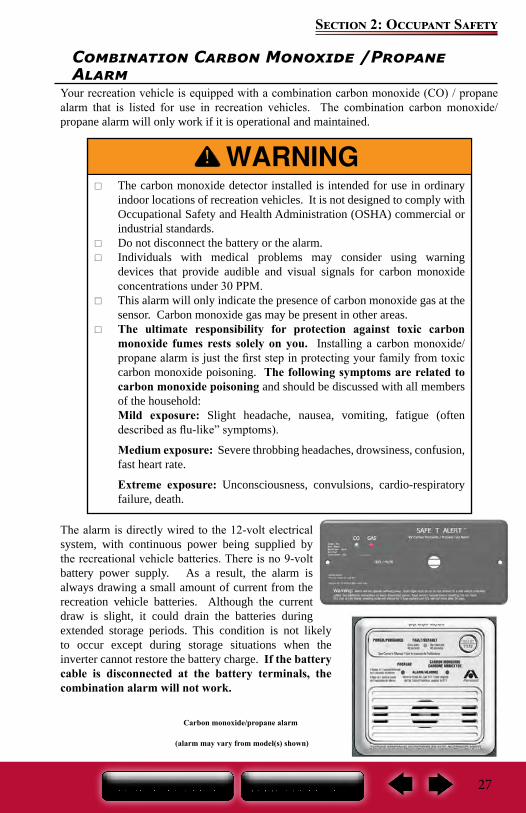
Combination Carbon Monoxide /Propane Alarm
Your recreation vehicle is equipped with a combination carbon monoxide (CO) / propane alarm that is listed for use in recreation vehicles. The combination carbon monoxide/propane alarm will only work if it is operational and maintained.
The alarm is directly wired to the 12-volt electrical system, with continuous power being supplied by the recreational vehicle batteries. There is no 9-volt battery power supply. As a result, the alarm is always drawing a small amount of current from the recreation vehicle batteries. Although the current draw is slight, it could drain the batteries during extended storage periods. This condition is not likely to occur except during storage situations when the inverter cannot restore the battery charge. If the battery cable is disconnected at the battery terminals, the combination alarm will not work.
The carbon monoxide detector installed is intended for use in ordinary indoor locations of recreation vehicles. It is not designed to comply with Occupational Safety and Health Administration (OSHA) commercial or industrial standards.
Do not disconnect the battery or the alarm. Individuals with medical problems may consider using warning
devices that provide audible and visual signals for carbon monoxide concentrations under 30 PPM.
This alarm will only indicate the presence of carbon monoxide gas at the sensor. Carbon monoxide gas may be present in other areas.
The ultimate responsibility for protection against toxic carbon monoxide fumes rests solely on you. Installing a carbon monoxide/propane alarm is just the first step in protecting your family from toxic carbon monoxide poisoning. The following symptoms are related to carbon monoxide poisoning and should be discussed with all members of the household:Mild exposure: Slight headache, nausea, vomiting, fatigue (often described as flu-like” symptoms).
Medium exposure: Severe throbbing headaches, drowsiness, confusion, fast heart rate.
Extreme exposure: Unconsciousness, convulsions, cardio-respiratory failure, death.
Carbon monoxide/propane alarm
(alarm may vary from model(s) shown)
28
Section 2: Occupant Safety
Be sure to read, understand and follow the owner’s information from the manufacturer of the combination CO/propane alarm. This includes information regarding the limited life of the alarm.Carbon monoxide (CO) is an insidious poison. It is a colorless, odorless and tasteless gas. Many cases of reported carbon monoxide poisoning indicate while victims are aware they are not well, they become so disoriented they are unable to save themselves by either exiting the recreational vehicle or calling for assistance. Young children and household pets may be the first affected.
Your combination carbon monoxide/propane alarm is designed to detect the toxic carbon monoxide fumes that result from incomplete combustion, such as those emitted from appliances, furnaces, fireplaces and auto exhaust.
A carbon monoxide/propane alarm is NOT A SUBSTITUTE for other combustible gas, fire or smoke alarms. This carbon monoxide alarm is designed to detect carbon monoxide gas from ANY source of combustion. It is not designed to detect smoke, fire or any other gas. Please note that there are hazards against which carbon monoxide detection may not be effective, such as natural gas leaks or explosions.
This alarm is designed to sense the presence of carbon monoxide/propane gas, however there are other combustible fumes or vapors that may be detected by the sensor including (but not limited to): acetone, alcohol, butane and gasoline.
These chemicals can be found in commonly used items such as deodorants, colognes, perfumes, adhesives, lacquer, kerosene, glues, wine, liquor, most cleaning agents and the propellants of aerosol cans.
High temperatures can activate glue and adhesive vapors. If you close up a recreational vehicle on a hot day, the chemicals used in its construction may be detected for months after the vehicle was constructed (for more information, refer to Sec. 2, Formaldehyde).
What you should do if the alarm sounds
1. Operate the RESET/SILENCE button.2. Call your emergency services (fire department or 911).3. Immediately move to fresh air (outdoors or by an open door or window). 4. Do not re-enter the premises or move away from the open door or window until the
emergency service responders have arrived, the premises have been aired out, and your alarm remains in its normal condition.
If your alarm reactivates within a 24 hour period, repeat steps 1-4 and call a qualified
Actuation of this detector indicates the presence of carbon monoxide which can kill you.
Never turn the 12-volt battery disconnect control to the off position and disconnect the battery cable to silence an alarm. The alarm will automatically sense when the level of carbon monoxide in the air reaches below dangerous levels. You should stay outside the vehicle in fresh air until the alarm is silenced. When the alarm sounds, do not stand too close to the alarm. The sound produced by the alarm is loud because it is designed to wake a person in an emergency. Prolonged exposure to the alarm at a close distance may be harmful to your hearing.
29
Section 2: Occupant Safety
appliance technician to investigate for sources of carbon monoxide from fuel burning equipment and appliances, and inspect for proper operation of this equipment. Make sure that motor vehicle(s) are not, and have not been, operating in an attached garage or adjacent to the recreation vehicle.
If problems are identified during this inspection, have the alarm serviced immediately. Note any combustion equipment not inspected by the technician and consult the manufacturer’s instructions or contact the manufacturer directly for more information about carbon monoxide safety and this alarm.
Alarm signals Normal operation: The LED will maintain a steady green light, indicating that the
alarm is powered. CO alarm condition: The red LED light will remain steady and the alarm will sound 4
“BEEPS” then silent for 5 seconds. These signals indicate immediate action is required. Propane gas alarm: The red LED flash and the alarm will sound a steady tone. These
signals indicate immediate action is required. Alarm malfunction/low battery: The gas LED will remain off and the Operational/
CO LED will alternate red/green and the alarm will sound once every 15 seconds. End of life alarm: The LED will flash red/red, green/green and the alarm will “BEEP”
every 25-30 seconds. The alarm should be immediately replaced.MaintenanceVacuum the alarm cover at least once a year. Clean the cover by hand using a cloth dampened in clean water. Dry with a soft cloth. Do not spray the front panel of the alarm with cleaning agents or waxes. This action may damage the sensor causing an alarm or cause the alarm to malfunction. Do not paint the face of the alarm.
Testing the combination carbon monoxide/propane alarm
The TEST/RESET button tests all ELECTRICAL functions of the alarm. The TEST/Mute switch is located on the front of the alarm. Press and hold the test button for 1 second. The alarm is working properly if the GREEN indicator light changes color to RED and the horn beeps 4 times. The Gas LED should also blink red.
Repair or replace the combination carbon monoxide/propane alarm when the alarm no longer functions. As with any electronic product, it has a limited life. Alarms that do not work cannot protect you.
Test the alarm operation after the motor home has been in storage, before each trip and at least once per week during use.
NOTE: Pressing the test button does not check the sensor opera-tion. Refer to the carbon monoxide/propane alarm manufacturers user’s manual provided with your recreation vehicle for additional information on testing the sensors.
30
Section 2: Occupant Safety
NOTE: The carbon monoxide/propane alarm manufacturer strongly recommends replacement of the detector five years after the date of purchase.
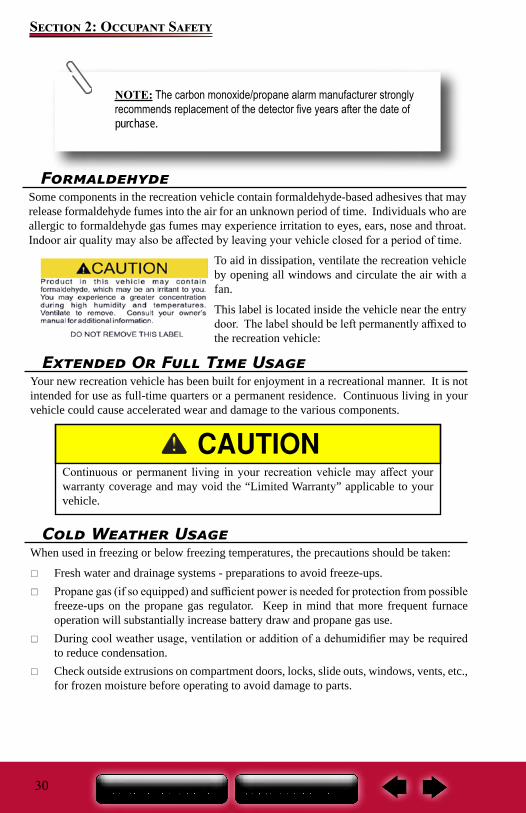
FormaldehydeSome components in the recreation vehicle contain formaldehyde-based adhesives that may release formaldehyde fumes into the air for an unknown period of time. Individuals who are allergic to formaldehyde gas fumes may experience irritation to eyes, ears, nose and throat. Indoor air quality may also be affected by leaving your vehicle closed for a period of time.
To aid in dissipation, ventilate the recreation vehicle by opening all windows and circulate the air with a fan.
This label is located inside the vehicle near the entry door. The label should be left permanently affixed to the recreation vehicle:
Extended Or Full Time UsageYour new recreation vehicle has been built for enjoyment in a recreational manner. It is not intended for use as full-time quarters or a permanent residence. Continuous living in your vehicle could cause accelerated wear and damage to the various components.
Continuous or permanent living in your recreation vehicle may affect your warranty coverage and may void the “Limited Warranty” applicable to your vehicle.
Cold Weather UsageWhen used in freezing or below freezing temperatures, the precautions should be taken:
Fresh water and drainage systems - preparations to avoid freeze-ups. Propane gas (if so equipped) and sufficient power is needed for protection from possible
freeze-ups on the propane gas regulator. Keep in mind that more frequent furnace operation will substantially increase battery draw and propane gas use.
During cool weather usage, ventilation or addition of a dehumidifier may be required to reduce condensation.
Check outside extrusions on compartment doors, locks, slide outs, windows, vents, etc., for frozen moisture before operating to avoid damage to parts.
31
Section 2: Occupant Safety
CondensationCondensation is a natural phenomenon. The amount of condensation will vary with climate conditions, particularly the relative humidity. Condensation occurs because there is water vapor present in the air. When the temperature reaches the “dew point” the water vapor in the air condenses and changes to a liquid form.
Proper ventilation or the use of a dehumidifier (customer supplied) will assist in controlling the condensation. Suggestions to eliminate warm moist air:
Crack open windows and roof vents to allow warm moist air to escape. Open the bath roof vent (if so equipped) approximately ½” when showering. Use the range hood fan (if so equipped) when cooking or washing dishes. Avoid hanging wet towels (or clothes) inside the recreation vehicle to dry. If found in cabinets or closets, open the doors slightly to provide ventilation.
Condensation may cause dampness, mildew, mold, staining and, if allowed to continue, it may result in damage to the recreation vehicle (damage caused by condensation is not warrantable). It can also lead to mold or mildew issues, which could be a health hazard.

32
Section 2: Occupant Safety
Notes:
33
Section 3: Pre-Travel Information
Vehicle LabelsDecals and data plates used throughout the motor home aid in its safe and efficient operation; others give service instructions. Read all decals, data and instruction plates before operating your recreation vehicle. Any decal, data or instruction plate painted over, damaged or removed should be replaced.
Keep a record of the 17-digit chassis vehicle identification number (VIN), the 9-digit serial number, and your license number in the event theft or vandalism requires you to supply this information to the authorities.
Weight TermsGAWR - Gross Axle Weight Rating: The value specified by the vehicle manufacturer as the load-carrying capacity of a single axle system, as measured at the tire-to-ground interfaces. This is the total weight a given axle is capable of carrying.
GCWR - Gross Combined Weight Rating: The value specified by the motor home manufacturer as the maximum allowable loaded weight of the motor home in combination with its towed trailer or towed vehicle. The tongue weight of a towed vehicle/ trailer counts as part of the motor home cargo.
GVWR - Gross Vehicle Weight Rating: The value specified by the manufacturer as the maximum permissible weight of the fully loaded motor home.
OCCC - Occupant and Cargo Carrying Capacity: Is equal to the GVWR of the motor home, minus the weight of the motor home, as completed at the factory, minus the weight of all occupants, including the driver, minus the weight of all personal cargo, minus the weight of a full tank of chassis engine fuel and, if applicable, minus the weight of a full tank of propane. The full weight of potable water, including the water heater and the tongue weight of a towed vehicle/ trailer counts as cargo in or on the motor home. Additions to or other changes made to the motor home after it left the factory will affect (reduce) the OCCC.
UVW - Unloaded Vehicle Weight: The weight of this motor home as manufactured at the factory with fuel, engine oil and coolants and if applicable, the weight of a full tank of propane.
Weight and Capacity LabelsThe following labels are located on the inward-facing surface of the main entry door of the motor home and on the lower sidewall left of the driver’s seat. OCCC Label (Occupant & Cargo Carrying Capacity): The upper portion of this yellow label is federally required
The factory-installed weight labels are specific to the recreation vehicle for which they are supplied and are not interchangeable. Do not remove these labels from your vehicle. If labels are missing contact your dealer or Customer Service for replacements.
Do not exceed any applicable motor home weight ratings. Doing so could damage your motor home or affect handling and braking characteristics.
Your motor home braking system is designed and rated for operation at GVWR not GCWR.
34
Section 3: Pre-Travel Information
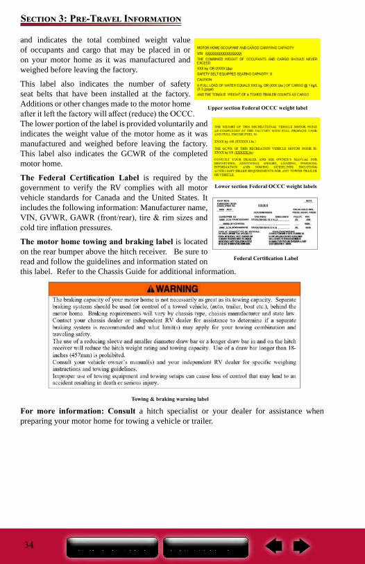
and indicates the total combined weight value of occupants and cargo that may be placed in or on your motor home as it was manufactured and weighed before leaving the factory.
This label also indicates the number of safety seat belts that have been installed at the factory. Additions or other changes made to the motor home after it left the factory will affect (reduce) the OCCC.The lower portion of the label is provided voluntarily and indicates the weight value of the motor home as it was manufactured and weighed before leaving the factory. This label also indicates the GCWR of the completed motor home.
The Federal Certification Label is required by the government to verify the RV complies with all motor vehicle standards for Canada and the United States. It includes the following information: Manufacturer name, VIN, GVWR, GAWR (front/rear), tire & rim sizes and cold tire inflation pressures.
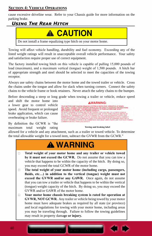
The motor home towing and braking label is located on the rear bumper above the hitch receiver. Be sure to read and follow the guidelines and information stated on this label. Refer to the Chassis Guide for additional information.
For more information: Consult a hitch specialist or your dealer for assistance when preparing your motor home for towing a vehicle or trailer.
Towing & braking warning label
Upper section Federal OCCC weight label
Lower section Federal OCCC weight labels
Federal Certification Label
35
Section 3: Pre-Travel Information
Loading Your Motorhome
Store and secure all loose items inside the motor home before traveling. Overlooked items can become dangerous projectiles during a sudden stop.
Distribute cargo side-to-side so the weight on each tire does not exceed one half of the GAWR for either axle. Make sure any tie down straps (if so equipped) on appliances or furniture are secure. Load heavy objects on the floor, or as low as possible.
Never load the motor home in excess of the GVWR or the GAWR for either axle. Overloading your motor home may result in adverse handling characteristics and damage to the chassis.
DO NOT EXCEED YOUR GVWR! This means you should weigh your vehicle as loaded for your normal travel to determine the actual weight. If you exceed the GVWR, you MUST remove items from the motor home, or drain liquids, then re-weigh the vehicle to ensure you have achieved a safe weight.
The actual weight of the vehicle, passengers, all options, liquids, the hitch weight of your towed vehicle and your personal cargo is important for you to know so you do not exceed the Gross Vehicle Weight Rating (GVWR) of the motor home. The volume of space available for storage may exceed the amount of available cargo capacity. Large storage compartments have been designed to accommodate normal camping items, which are bulky, but not necessarily heavy.
Your recreation vehicle’s load capacity is designated by weight, not by volume, so you cannot necessarily use all available space when loading the vehicle. Do not exceed your GVWR and ensure you are loading the vehicle as evenly as you can for the best possible handling. Ensure heavy items are secured so they do not shift during travel.
Store items in areas designated for storage. Do not store anything in the areas reserved for the converter, electrical panels, furnace or water heater, etc.
For traveling safety, it is important to make sure the tie down straps are secured on all appliances such as the toaster, coffee maker, etc. Vibration during travel will move the appliances, creating the potential for them to fall out of their cabinets possibly causing injury.
36
Section 3: Pre-Travel Information
Weighing Your Motor homeWhen your motor home is loaded you should have it weighed. The actual weight of the motor home, passengers, all options, liquids, the hitch weight of your towed vehicle and your personal cargo is important for you to know so you do not exceed the GVWR. There are two important factors when loading your motor home, total weight and balance.
It is imperative that you verify compliance within all applicable weight ratings. Overloading your motor home will void the Limited Warranty and the warranties of many component part manufacturers.
Periodically weigh your motor home at a public scale to determine proper load distribution. To obtain the side-to-side weights, there needs to be enough space on either side of the scale to accommodate the motor home being partially off the scale.
Different types or scales may require different procedures when weighting the motor home. The motor home must remain as level as possible on the scale (even if an axle is not physically on the scale). To obtain the side-to-side weights, make sure there is enough space
on either side of the scale to accommodate the motor home being partially off the scale.
If a boat, trailer or other vehicle is being towed, it should be weighed separately. Combine this weight with the motor home’s Gross Vehicle Weight (GVW) to ensure the total combined weight does not exceed the GCWR.
It is important to redistribute the load to avoid component failure as well as to improve the handling characteristics of the vehicle.
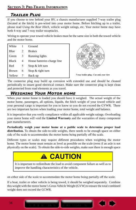
Trailer PlugIf you choose to tow behind your RV, a chassis manufacturer supplied 7-way trailer plug (located at the hitch) is pre-wired into your motor home. Before hitching up to a trailer, please read Using the Rear Hitch, vehicle weight ratings, etc. Your motor home may have both 4-way and 7-way trailer receptacles.
Wiring to operate your towed vehicle brakes must be the same size in both the towed vehicle and the motor home.
White 1 GroundBlue 2 BrakesGreen 3 Running lightsBlack 4 House batteries charge lineRed 5 Stop & left turnBrown 6 Stop & right turnYellow 7 Back up
The connector plug may build up corrosion with extended use and should be cleaned periodically to insure good electrical contact. Make sure the connector plug is kept clean and protected from road elements as you travel.
7-way trailer plug - Car end, rear view
37
Section 3: Pre-Travel Information
Dump the gray and black water holding tanks before traveling to avoid carrying unnecessary weight. Traveling with the tanks full can affect your fuel consumption, and depending on the location of the tanks, can affect your vehicle handling characteristics. If you are dry camping and cannot immediately empty your holding tanks, reduce your vehicle speed until you reach a dumping station.
Once actual weights are obtained, compare them to the Weight Information Label weight ratings to ensure you are below the posted minimum ratings.
If there is a difference in the weights on one side of the vehicle as compared to weights on the other side, components (tires, wheels, brakes, springs, etc.) on the heavier side may be overloaded, although the total axle load is within the GAWR.
See the Weight Terms and Loading Your RV sections for important information on how towing a vehicle affects the motor home weight.

38
Section 3: Pre-Travel Information
Notes:
39
Section 4: Vehicle Operations
Vehicle OperationYour motor home will travel safely and comfortably at highway speed limits. However, it will take longer than a passenger automobile to reach that speed. Allow more time to go around the vehicle you are passing. Avoid situations that might require sudden momentum changes as the length of the motor home affects your ability to quickly cut back into traffic. Swerves and sharp turns, especially at high speeds, could result in loss of control of the motor home.
The motor home has a longer turning radius. When turning, check the road clearance and be aware of others, especially if towing a vehicle behind your motor home.
Adverse weather conditions and extremes in terrain may affect the performance and handling of your vehicle. Do not operate the cruise control on icy or extremely wet roads, gravel roads, winding roads, in heavy traffic, or in any other traffic situation where a constant speed cannot be maintained. Use care when accelerating or decelerating on a slippery surface. Abrupt speed changes can cause skidding and loss of control.
Braking & StoppingEven though your motor home is equipped with brakes designed for its Gross Vehicle Weight Rating (GVWR) we suggest you practice stopping away from traffic until you become accustomed to your motor home’s stopping distance. Your motor home is equipped with a third brake light that activates when the brakes are engaged.
When descending a long hill, shift the transmission into a lower gear and engage the auxiliary engine braking. Auxiliary engine brake engagement is activated by a switch on the driver’s console.
See the chassis owner’s manual for additional information. The transmission and engine will help in controlling downhill speed and can lengthen brake life. The distance required to stop the motor home is greater than an automobile’s.
Driving through water deep enough to wet the brakes may affect stopping distance or cause the vehicle to pull to one side. Check the motor home’s brake operation in a safe area to be sure they have not been affected. Never operate any vehicle if a difference in braking efficiency is noticeable.
Parking BrakeThe parking brake should be engaged when the motor home is parked. Never drive your motor home with the parking brake engaged as this will reduce braking effectiveness and
Your motor home chassis braking system is rated for operation at GVWR not GCWR.
NOTE: CALIFORNIA TIRE CHAIN NOTICE:YOUR MOTOR HOME MAY NOT BE OPERATED WITH TIRE CHAINS
40
Section 4: Vehicle Operations
Using The Rear Hitch
Towing will affect vehicle handling, durability and fuel economy. Exceeding any of the listed weight ratings will result in unacceptable overall vehicle performance. Your safety and satisfaction require proper use of correct equipment.
The factory installed towing hitch on this vehicle is capable of pulling 15,000 pounds of load (maximum), and a maximum vertical (tongue) weight of 1,500 pounds. A hitch bar of appropriate strength and steel should be selected to meet the capacities of the towing receptor.
Always use safety chains between the motor home and the towed trailer or vehicle. Cross the chains under the tongue and allow for slack when turning corners. Connect the safety chains to the vehicle frame or hook retainers. Never attach the safety chains to the bumper.
Before descending a steep or long grade when towing a trailer or vehicle, reduce speed and shift the motor home into a lower gear to control vehicle speed. Avoid frequent or prolonged brake application, which can cause overheating or brake failure.
By definition the GCWR is “the maximum total weight rating allowed for a vehicle and any attachment, such as a trailer or towed vehicle. To determine the total allowable weight for a towed item, subtract the GVWR from the GCWR.”
Do not install a frame equalizing type hitch on your motor home.
Towing and braking label
Total weight of your motor home and any trailer or vehicle towed by it must not exceed the GCWR. Do not assume that you can tow a vehicle that happens to be within the capacity of the hitch. By doing so, you may exceed the total GCWR of the motor home.
The total weight of your motor home (including cargo, passengers, fluids, etc…) in addition to the vertical (tongue) weight must not exceed the GVWR and/or any GAWR. Once again, do not assume that you can tow a trailer or vehicle that happens to be within the vertical (tongue) weight capacity of the hitch. By doing so, you may exceed the GVWR and/or GAWR of the motor home.
Your motor home chassis breaking system is rated for operation at GVWR, NOT GCWR. Any trailer or vehicle being towed by your motor home must have adequate brakes as required by all state (or province) and local regulations for towing with your motor home, including areas you may be traveling through. Failure to follow the towing guidelines may result in property damage or injury.
cause excessive driveline wear. Refer to your Chassis guide for more information on the parking brake.
41
Section 4: Vehicle Operations
In addition, a separate supplemental braking system must be installed if the towed trailer or vehicle meets or exceeds the minimum weight determined by the chassis manufacturer (this minimum weight rating will vary by chassis and chassis manufacturer).
Contact your dealer for assistance in determining whether a separate braking system is recommended for your towing and traveling safety. Failure to follow these instructions will create a safety hazard and may result in an accident.
MaintenanceKeep the hitch clean along with your general frame maintenance.
At the beginning of the season, and monthly or thereafter, clean the inside of the receiver tube with a wire brush and spray with a silicone spray.
Always remove the utility mount from the receiver when it is not in use. This will help prevent the utility mount from rusting to the tube.
Periodically check the bolts for tightness. They need to be torqued to the proper setting (refer to your Chassis Guide).
Refer to the Trailer Plug section for information on the trailer plug hook-up.
Step Well & CoverAir powered step well cover The step well cover can be extended or retracted using the “step cover” switch located on the passenger side console.
Make sure there are no obstructions when operating the step well cover. To avoid personal injury, do not operate the step well cover when standing in the step well.
Entrance StepYour motor home is equipped with an electric entrance step. To operate, locate the “Step” control located on the passenger side console (the 12-volt battery disconnect switch must be ON). If the step encounters an immovable object, such as a curb, while being deployed, it will stop and shut down in that position. It will retract normally when the door is closed.
STEP WITH CONTROL UNIT--(Normal Operation/Automatic Mode) Close the door. The step should retract and lock in the ‘up’ position (under step
light is not on).
LOOK BEFORE ENTERING OR EXITING YOUR MOTOR HOME! When opening the door from the outside, make sure you are not obstructing
the path of the entrance step. Step deployment takes approximately two seconds. Keep hands and fingers clear while extending or retracting.
Look before you exit. It is possible to deliberately lock the steps in the retracted or closed position with the rocker switch. Make sure the steps are fully deployed before exiting the motor home. Stepping on a partially extended step can cause damage to the step frame.
42
Section 4: Vehicle Operations
Entrance DoorAlways hold onto the entrance door when opening or closing it. Damage caused because you failed to do so is not covered by the Limited Warranty.
Open the door. The step should extend and lock in the ‘down’ position with the under step light illuminated.
STEP WITH CONTROL UNIT--(Step Lock Function/Stationary Extended Mode.) If your step is equipped with an override switch, turn it to the ‘ON’ position. The
step should remain extended with the under step light ‘off’ when the door is closed. With the step override switch turned ‘ON’, the step extended, and the entrance
door closed, turn the vehicle ignition on. The ignition override system will go into effect and the step will automatically retract.
Turn the vehicle ignition off and open the door. The step will extend and lock in the ‘down’ position. This is the ‘auto extend’ feature. When the vehicle ignition is turned on, the step will always activate with the door movement, regardless of the step switch position.
NOTE: In the event the entrance door is left open, the light will turn ‘off’ after 5 minutes.
Do not hold the switch in for longer than it takes to extend or retract the step. Doing so may result in damage to the motor home.
NOTE:If the yellow wire from the four-way connector is not con-nected to an ignition power source, the ignition safety system will be inoperative and the step will remain in the extended position. In this case, the step lock switch must be placed in the automatic mode position for the step to retract.
NOTE:If the yellow wire from the four-way connector is not con-nected to an ignition power source, the ignition will not cause the step to retract if the step lock switch is placed in the automatic mode position, regardless of the door position.
43
Section 4: Vehicle Operations
Make sure the entrance door is completely closed and locked when traveling. Locking the door helps prevent it from opening unintentionally and keeps intruders from your recreation vehicle.
The entrance screen door may be equipped with a slide panel that allows access to the entrance door handle and locks. The entrance door may also be equipped with both a regular door lock and a dead bolt lock.
KeysSeveral keys are provided when you purchase your vehicle. Most keys have an individual key number stamped on the plate. Record these key numbers and keep the information in a safe place. You can order a key blank from your dealer to have duplicate keys made. If you lose the keys, contact your dealer or a locksmith for assistance.
NOTE:Locks on entrance and baggage doors need biannual lubri-cation using a light coat of silicone spray. Conditions such as rain, salt, dust and pollution may increase the maintenance needs.
Keyless EntryThe keyless entry system includes a keypad integrated grab handle and a keyless entry FOB transmitter and receiver (either the Standard mode or Cargo mode).
The following is an overview of the keyless entry system operation and functions. Refer to the manufacturer’s Keyless Entry Consumer Manual for detailed instructions or visit the manufacturer’s website.
Keyless entry FOB transmitter and receiver functions:Standard Mode FOB (2 button):
CLOSED PADLOCK ICON: Locks doors and arms security system.
OPEN PADLOCK ICON: Unlocks doors and disarms security system and activates the porch light.
Cargo Mode FOB (4 button): ENTRY LOCK: Locks entry door and arms the security system. ENTRY UNLOCK: Unlocks the entry door and disarms the security system and
activates the porch light. CARGO LOCK: Locks compartment doors and arms the security system. CARGO UNLOCK: Unlocks compartment doors and disarms the security system.
Standard Mode FOB Keypad
Cargo Mode FOB
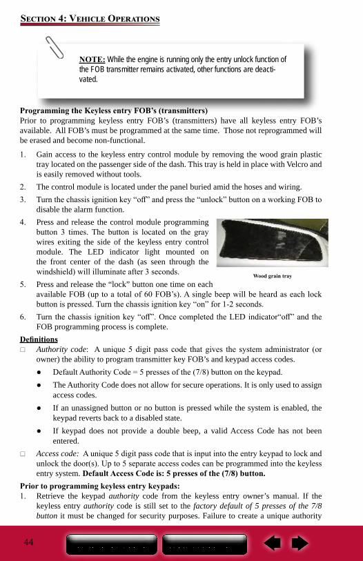
44
Section 4: Vehicle Operations
Programming the Keyless entry FOB’s (transmitters)Prior to programming keyless entry FOB’s (transmitters) have all keyless entry FOB’s available. All FOB’s must be programmed at the same time. Those not reprogrammed will be erased and become non-functional.
1. Gain access to the keyless entry control module by removing the wood grain plastic tray located on the passenger side of the dash. This tray is held in place with Velcro and is easily removed without tools.
2. The control module is located under the panel buried amid the hoses and wiring.3. Turn the chassis ignition key “off” and press the “unlock” button on a working FOB to
disable the alarm function.4. Press and release the control module programming
button 3 times. The button is located on the gray wires exiting the side of the keyless entry control module. The LED indicator light mounted on the front center of the dash (as seen through the windshield) will illuminate after 3 seconds.
5. Press and release the “lock” button one time on each available FOB (up to a total of 60 FOB’s). A single beep will be heard as each lock button is pressed. Turn the chassis ignition key “on” for 1-2 seconds.
6. Turn the chassis ignition key “off”. Once completed the LED indicator“off” and the FOB programming process is complete.
Definitions Authority code: A unique 5 digit pass code that gives the system administrator (or
owner) the ability to program transmitter key FOB’s and keypad access codes. ● Default Authority Code = 5 presses of the (7/8) button on the keypad. ● The Authority Code does not allow for secure operations. It is only used to assign
access codes. ● If an unassigned button or no button is pressed while the system is enabled, the
keypad reverts back to a disabled state. ● If keypad does not provide a double beep, a valid Access Code has not been
entered. Access code: A unique 5 digit pass code that is input into the entry keypad to lock and
unlock the door(s). Up to 5 separate access codes can be programmed into the keyless entry system. Default Access Code is: 5 presses of the (7/8) button.
Prior to programming keyless entry keypads:1. Retrieve the keypad authority code from the keyless entry owner’s manual. If the
keyless entry authority code is still set to the factory default of 5 presses of the 7/8 button it must be changed for security purposes. Failure to create a unique authority
Wood grain tray
NOTE: While the engine is running only the entry unlock function of the FOB transmitter remains activated, other functions are deacti-vated.
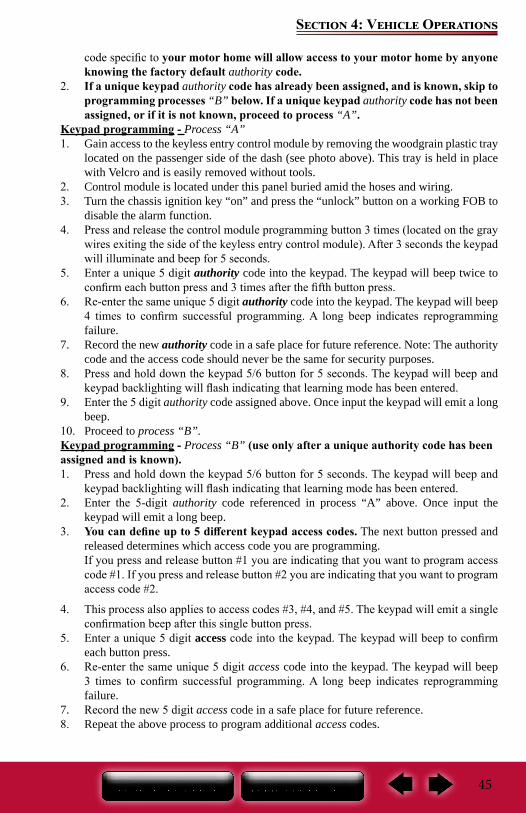
45
Section 4: Vehicle Operations
code specific to your motor home will allow access to your motor home by anyone knowing the factory default authority code.
2. If a unique keypad authority code has already been assigned, and is known, skip to programming processes “B” below. If a unique keypad authority code has not been assigned, or if it is not known, proceed to process “A”.
Keypad programming - Process “A”1. Gain access to the keyless entry control module by removing the woodgrain plastic tray
located on the passenger side of the dash (see photo above). This tray is held in place with Velcro and is easily removed without tools.
2. Control module is located under this panel buried amid the hoses and wiring.3. Turn the chassis ignition key “on” and press the “unlock” button on a working FOB to
disable the alarm function.4. Press and release the control module programming button 3 times (located on the gray
wires exiting the side of the keyless entry control module). After 3 seconds the keypad will illuminate and beep for 5 seconds.
5. Enter a unique 5 digit authority code into the keypad. The keypad will beep twice to confirm each button press and 3 times after the fifth button press.
6. Re-enter the same unique 5 digit authority code into the keypad. The keypad will beep 4 times to confirm successful programming. A long beep indicates reprogramming failure.
7. Record the new authority code in a safe place for future reference. Note: The authority code and the access code should never be the same for security purposes.
8. Press and hold down the keypad 5/6 button for 5 seconds. The keypad will beep and keypad backlighting will flash indicating that learning mode has been entered.
9. Enter the 5 digit authority code assigned above. Once input the keypad will emit a long beep.
10. Proceed to process “B”.Keypad programming - Process “B” (use only after a unique authority code has been assigned and is known).1. Press and hold down the keypad 5/6 button for 5 seconds. The keypad will beep and
keypad backlighting will flash indicating that learning mode has been entered.2. Enter the 5-digit authority code referenced in process “A” above. Once input the
keypad will emit a long beep.3. You can define up to 5 different keypad access codes. The next button pressed and
released determines which access code you are programming.If you press and release button #1 you are indicating that you want to program access code #1. If you press and release button #2 you are indicating that you want to program access code #2.
4. This process also applies to access codes #3, #4, and #5. The keypad will emit a single confirmation beep after this single button press.
5. Enter a unique 5 digit access code into the keypad. The keypad will beep to confirm each button press.
6. Re-enter the same unique 5 digit access code into the keypad. The keypad will beep 3 times to confirm successful programming. A long beep indicates reprogramming failure.
7. Record the new 5 digit access code in a safe place for future reference.8. Repeat the above process to program additional access codes.
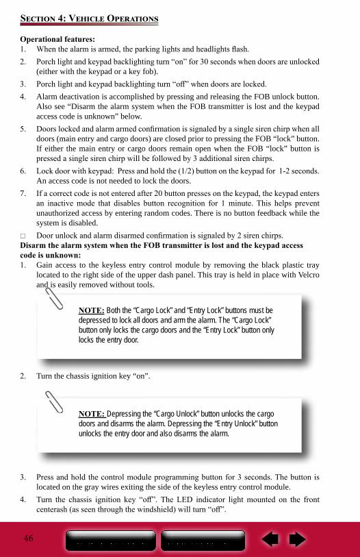
46
Section 4: Vehicle Operations
Operational features:1. When the alarm is armed, the parking lights and headlights flash.2. Porch light and keypad backlighting turn “on” for 30 seconds when doors are unlocked
(either with the keypad or a key fob).3. Porch light and keypad backlighting turn “off” when doors are locked.4. Alarm deactivation is accomplished by pressing and releasing the FOB unlock button.
Also see “Disarm the alarm system when the FOB transmitter is lost and the keypad access code is unknown” below.
5. Doors locked and alarm armed confirmation is signaled by a single siren chirp when all doors (main entry and cargo doors) are closed prior to pressing the FOB “lock” button. If either the main entry or cargo doors remain open when the FOB “lock” button is pressed a single siren chirp will be followed by 3 additional siren chirps.
6. Lock door with keypad: Press and hold the (1/2) button on the keypad for 1-2 seconds. An access code is not needed to lock the doors.
7. If a correct code is not entered after 20 button presses on the keypad, the keypad enters an inactive mode that disables button recognition for 1 minute. This helps prevent unauthorized access by entering random codes. There is no button feedback while the system is disabled.
Door unlock and alarm disarmed confirmation is signaled by 2 siren chirps.Disarm the alarm system when the FOB transmitter is lost and the keypad access code is unknown:1. Gain access to the keyless entry control module by removing the black plastic tray
located to the right side of the upper dash panel. This tray is held in place with Velcro and is easily removed without tools.
2. Turn the chassis ignition key “on”.
3. Press and hold the control module programming button for 3 seconds. The button is located on the gray wires exiting the side of the keyless entry control module.
4. Turn the chassis ignition key “off”. The LED indicator light mounted on the front centerash (as seen through the windshield) will turn “off”.
NOTE: Both the “Cargo Lock” and “Entry Lock” buttons must be depressed to lock all doors and arm the alarm. The “Cargo Lock” button only locks the cargo doors and the “Entry Lock” button only locks the entry door.
NOTE: Depressing the “Cargo Unlock” button unlocks the cargo doors and disarms the alarm. Depressing the “Entry Unlock” button unlocks the entry door and also disarms the alarm.
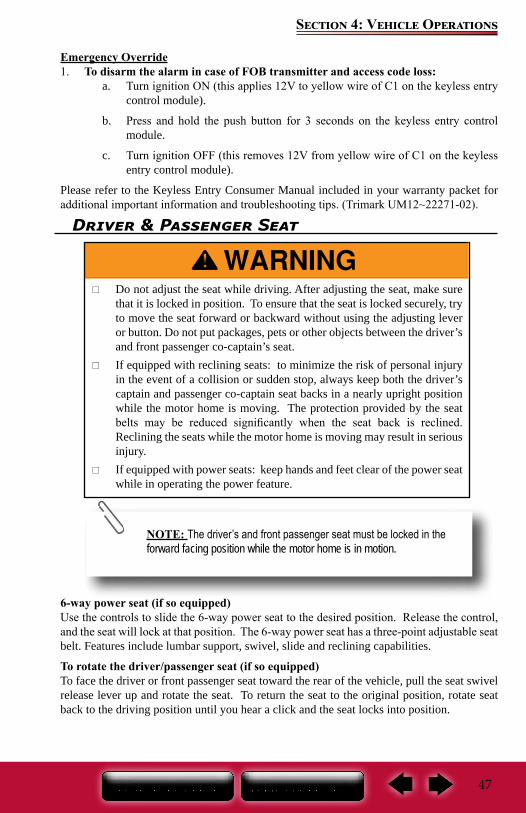
47
Section 4: Vehicle Operations
Emergency Override1. To disarm the alarm in case of FOB transmitter and access code loss:
a. Turn ignition ON (this applies 12V to yellow wire of C1 on the keyless entry control module).
b. Press and hold the push button for 3 seconds on the keyless entry control module.
c. Turn ignition OFF (this removes 12V from yellow wire of C1 on the keyless entry control module).
Please refer to the Keyless Entry Consumer Manual included in your warranty packet for additional important information and troubleshooting tips. (Trimark UM12~22271-02).
Driver & Passenger Seat
6-way power seat (if so equipped)Use the controls to slide the 6-way power seat to the desired position. Release the control, and the seat will lock at that position. The 6-way power seat has a three-point adjustable seat belt. Features include lumbar support, swivel, slide and reclining capabilities.
To rotate the driver/passenger seat (if so equipped)To face the driver or front passenger seat toward the rear of the vehicle, pull the seat swivel release lever up and rotate the seat. To return the seat to the original position, rotate seat back to the driving position until you hear a click and the seat locks into position.
Do not adjust the seat while driving. After adjusting the seat, make sure that it is locked in position. To ensure that the seat is locked securely, try to move the seat forward or backward without using the adjusting lever or button. Do not put packages, pets or other objects between the driver’s and front passenger co-captain’s seat.
If equipped with reclining seats: to minimize the risk of personal injury in the event of a collision or sudden stop, always keep both the driver’s captain and passenger co-captain seat backs in a nearly upright position while the motor home is moving. The protection provided by the seat belts may be reduced significantly when the seat back is reclined. Reclining the seats while the motor home is moving may result in serious injury.
If equipped with power seats: keep hands and feet clear of the power seat while in operating the power feature.
NOTE: The driver’s and front passenger seat must be locked in the forward facing position while the motor home is in motion.
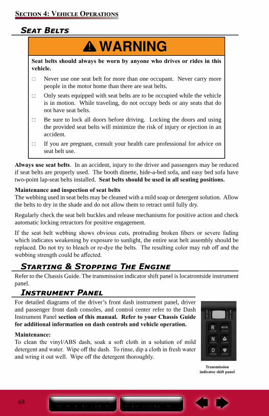
48
Section 4: Vehicle Operations
Seat Belts
Always use seat belts. In an accident, injury to the driver and passengers may be reduced if seat belts are properly used. The booth dinette, hide-a-bed sofa, and easy bed sofa have two-point lap-seat belts installed. Seat belts should be used in all seating positions.
Maintenance and inspection of seat beltsThe webbing used in seat belts may be cleaned with a mild soap or detergent solution. Allow the belts to dry in the shade and do not allow them to retract until fully dry.
Regularly check the seat belt buckles and release mechanisms for positive action and check automatic locking retractors for positive engagement.
If the seat belt webbing shows obvious cuts, protruding broken fibers or severe fading which indicates weakening by exposure to sunlight, the entire seat belt assembly should be replaced. Do not try to bleach or re-dye the belts. The resulting color may rub off and the webbing strength could be affected.
Seat belts should always be worn by anyone who drives or rides in this vehicle.
Never use one seat belt for more than one occupant. Never carry more people in the motor home than there are seat belts.
Only seats equipped with seat belts are to be occupied while the vehicle is in motion. While traveling, do not occupy beds or any seats that do not have seat belts.
Be sure to lock all doors before driving. Locking the doors and using the provided seat belts will minimize the risk of injury or ejection in an accident.
If you are pregnant, consult your health care professional for advice on seat belt use.
Starting & Stopping The EngineRefer to the Chassis Guide. The transmission indicator shift panel is locatrontside instrument panel.
Transmission indicator shift panel
Instrument PanelFor detailed diagrams of the driver’s front dash instrument panel, driver and passenger front dash consoles, and control center refer to the Dash Instrument Panel section of this manual. Refer to your Chassis Guide for additional information on dash controls and vehicle operation.
Maintenance:To clean the vinyl/ABS dash, soak a soft cloth in a solution of mild detergent and water. Wipe off the dash. To rinse, dip a cloth in fresh water and wring it out well. Wipe off the detergent thoroughly.
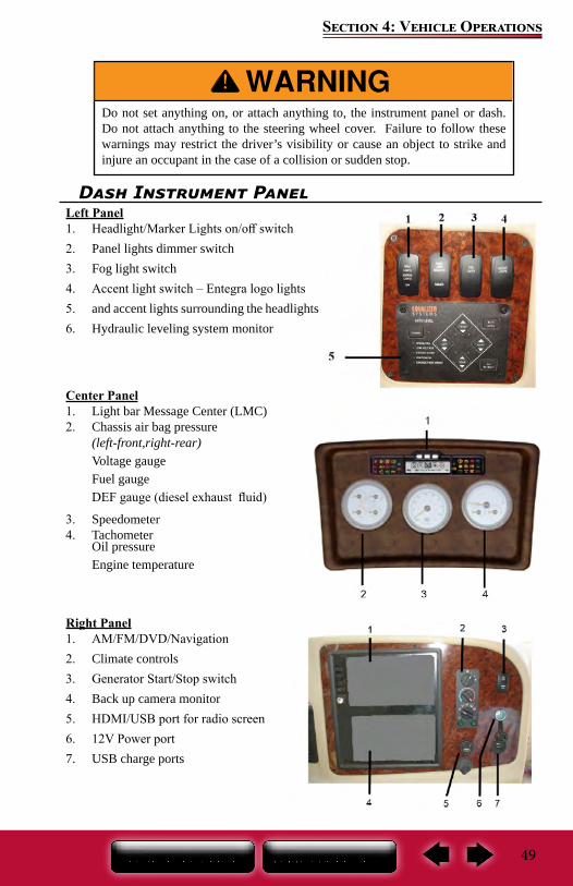
49
Section 4: Vehicle Operations
Dash Instrument PanelLeft Panel1. Headlight/Marker Lights on/off switch2. Panel lights dimmer switch3. Fog light switch4. Accent light switch – Entegra logo lights5. and accent lights surrounding the headlights6. Hydraulic leveling system monitor
Center Panel1. Light bar Message Center (LMC)2. Chassis air bag pressure
(left-front,right-rear)Voltage gaugeFuel gaugeDEF gauge (diesel exhaust fluid)
3. Speedometer4. Tachometer
Oil pressureEngine temperature
Right Panel1. AM/FM/DVD/Navigation2. Climate controls3. Generator Start/Stop switch4. Back up camera monitor5. HDMI/USB port for radio screen6. 12V Power port7. USB charge ports
Do not set anything on, or attach anything to, the instrument panel or dash. Do not attach anything to the steering wheel cover. Failure to follow these warnings may restrict the driver’s visibility or cause an object to strike and injure an occupant in the case of a collision or sudden stop.
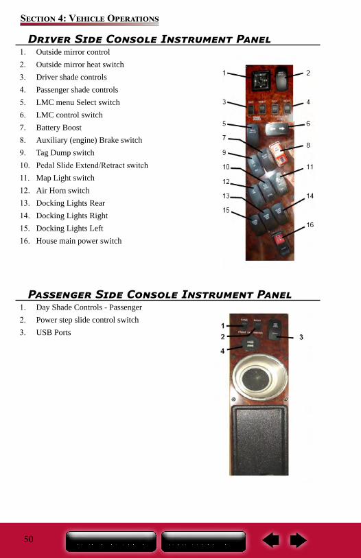
50
Section 4: Vehicle Operations
Driver Side Console Instrument Panel1. Outside mirror control2. Outside mirror heat switch3. Driver shade controls4. Passenger shade controls5. LMC menu Select switch6. LMC control switch7. Battery Boost8. Auxiliary (engine) Brake switch9. Tag Dump switch10. Pedal Slide Extend/Retract switch11. Map Light switch12. Air Horn switch13. Docking Lights Rear14. Docking Lights Right15. Docking Lights Left16. House main power switch
Passenger Side Console Instrument Panel1. Day Shade Controls - Passenger2. Power step slide control switch3. USB Ports
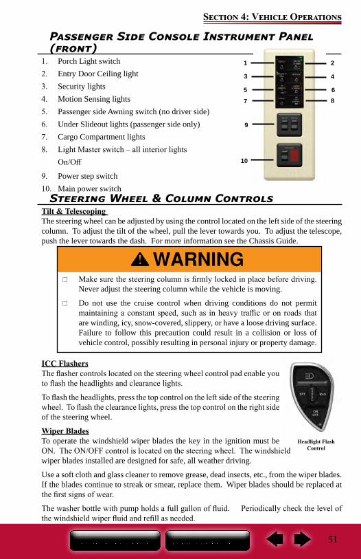
51
Section 4: Vehicle Operations
Passenger Side Console Instrument Panel (front)
1. Porch Light switch2. Entry Door Ceiling light3. Security lights4. Motion Sensing lights5. Passenger side Awning switch (no driver side)6. Under Slideout lights (passenger side only)7. Cargo Compartment lights8. Light Master switch – all interior lights
On/Off
9. Power step switch10. Main power switch
Steering Wheel & Column ControlsTilt & Telescoping The steering wheel can be adjusted by using the control located on the left side of the steering column. To adjust the tilt of the wheel, pull the lever towards you. To adjust the telescope, push the lever towards the dash. For more information see the Chassis Guide.
ICC FlashersThe flasher controls located on the steering wheel control pad enable you to flash the headlights and clearance lights.
To flash the headlights, press the top control on the left side of the steering wheel. To flash the clearance lights, press the top control on the right side of the steering wheel.
Wiper BladesTo operate the windshield wiper blades the key in the ignition must be ON. The ON/OFF control is located on the steering wheel. The windshield wiper blades installed are designed for safe, all weather driving.
Use a soft cloth and glass cleaner to remove grease, dead insects, etc., from the wiper blades. If the blades continue to streak or smear, replace them. Wiper blades should be replaced at the first signs of wear.
The washer bottle with pump holds a full gallon of fluid. Periodically check the level of the windshield wiper fluid and refill as needed.
Headlight Flash Control
Make sure the steering column is firmly locked in place before driving. Never adjust the steering column while the vehicle is moving.
Do not use the cruise control when driving conditions do not permit maintaining a constant speed, such as in heavy traffic or on roads that are winding, icy, snow-covered, slippery, or have a loose driving surface. Failure to follow this precaution could result in a collision or loss of vehicle control, possibly resulting in personal injury or property damage.
6
4
2
8 7
5
3
1
9
10
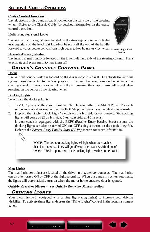
52
Section 4: Vehicle Operations
Driver’s Console Control PanelHornsThe air horn control switch is located on the driver’s console panel. To activate the air horn system, press the switch to the “on” position. To sound the horn, press on the center of the steering wheel. If the air horn switch is in the off position, the chassis horn will sound when pressing on the center of the steering wheel.
Docking LightsTo activate the docking lights:
1. 12V DC power to the coach must be ON. Depress either the MAIN POWER switch in the entrance door stepwell, or the HOUSE power switch on the left driver console.
2. Depress the single “Dock Light” switch on the left side driver console. Six docking lights will come on (2 on left side, 2 on right side, and 2 in rear).If your coach is equipped with the PEPS (Passive Entry Passive Start) system, the docking lights can also be turned ON and OFF using a button on the special key fob. Refer to the Passive Entry Passive Start (PEPS) section for more information.
Map LightsThe map light control(s) are located on the driver and passenger consoles. The map lights can also be turned ON or OFF at the light assembly. When the control is set on automatic, the lights will automatically turn on when the motor home entrance door is opened.
Outside Rearview Mirrors – see Outside Rearview Mirror section
Driving LightsYour motor home is equipped with driving lights (fog lights) to increase your driving visibility. To activate these lights, depress the “Drive Lights” control in the front instrument panel.
Cruise Control FunctionThe electronic cruise control pad is located on the left side of the steering wheel. Refer to the Chassis Guide for detailed information on the cruise control operation.
Multi–Function Signal Lever
The multi-function signal lever located on the steering column controls the turn signals, and the headlight high/low beam. Pull the end of the handle forward towards you to switch from high beam to low beam, or vice versa.
Hazard-Warning FlasherThe hazard signal control is located on the lower left hand side of the steering column. Press to activate and press again to turn them off.
Clearance Light Flash Control
NOTE: The two rear docking lights will light when the coach is shifted into reverse. They will go off when the coach is shifted out of reverse. This happens even if the docking light switch is turned OFF.
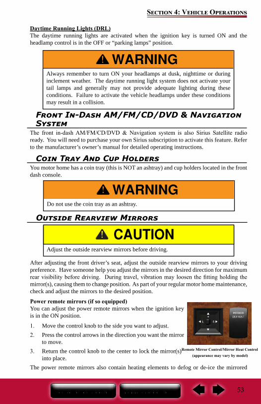
53
Section 4: Vehicle Operations
Always remember to turn ON your headlamps at dusk, nighttime or during inclement weather. The daytime running light system does not activate your tail lamps and generally may not provide adequate lighting during these conditions. Failure to activate the vehicle headlamps under these conditions may result in a collision.
Coin Tray And Cup HoldersYou motor home has a coin tray (this is NOT an ashtray) and cup holders located in the front dash console.
Do not use the coin tray as an ashtray.
Front In-Dash AM/FM/CD/DVD & Navigation System
The front in-dash AM/FM/CD/DVD & Navigation system is also Sirius Satellite radio ready. You will need to purchase your own Sirius subscription to activate this feature. Refer to the manufacturer’s owner’s manual for detailed operating instructions.
Outside Rearview Mirrors
After adjusting the front driver’s seat, adjust the outside rearview mirrors to your driving preference. Have someone help you adjust the mirrors in the desired direction for maximum rear visibility before driving. During travel, vibration may loosen the fitting holding the mirror(s), causing them to change position. As part of your regular motor home maintenance, check and adjust the mirrors to the desired position.
Power remote mirrors (if so equipped)You can adjust the power remote mirrors when the ignition key is in the ON position.
1. Move the control knob to the side you want to adjust.2. Press the control arrows in the direction you want the mirror
to move.3. Return the control knob to the center to lock the mirror(s)
into place.The power remote mirrors also contain heating elements to defog or de-ice the mirrored
Adjust the outside rearview mirrors before driving.
Remote Mirror Control/Mirror Heat Control(appearance may vary by model)
Daytime Running Lights (DRL)The daytime running lights are activated when the ignition key is turned ON and the headlamp control is in the OFF or “parking lamps” position.
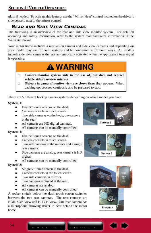
54
Section 4: Vehicle Operations
glass if needed. To activate this feature, use the “Mirror Heat” control located on the driver’s side console next to the mirror control.
Rear and Side View CamerasThe following is an overview of the rear and side view monitor system. For detailed operating and safety information, refer to the system manufacturer’s information in the Warranty Packet.
Your motor home includes a rear vision camera and side view cameras and depending on your model may use different systems and be configured in different ways. All models include side view cameras that are automatically activated when the appropriate turn signal is operating.
There are 5 different backup camera systems depending on which model you have.
System 1: ● Dual 9” touch screens on the dash. ● Camera controls in touch screen. ● Two side cameras on the body, one camera
at the rear. ● All cameras are HD digital cameras. ● All cameras can be manually controlled.
System 2: ● Dual 9” touch screens on the dash. ● Camera controls in touch screen. ● Two side cameras in the mirrors and a single
rear camera. ● Side cameras are analog, rear camera is HD
digital. ● All cameras can be manually controlled.
System 3: ● Single 9” touch screen in the dash. ● Camera controls in the touch screen. ● Two side cameras in mirrors. ● Two cameras mounted at the rear. ● All cameras are analog. ● All cameras can be manually controlled.
A rocker switch below the dash touch screen switches between the two rear cameras. The rear cameras are HORIZON view and HITCH view. One rear camera has a microphone allowing driver to hear behind the motor home.
Camera/monitor system aids in the use of, but does not replace vehicle side/rear-view mirrors.
Objects in camera/monitor view are closer than they appear. When backing up, proceed cautiously and be prepared to stop.
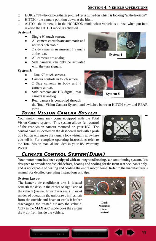
55
Section 4: Vehicle Operations
HORIZON - the camera that is pointed up is turned on which is looking “at the horizon”. HITCH - the camera pointing down at the hitch. AUTO - the camera is in the HORIZON mode when vehicle is at rest, when put into
reverse the HITCH mode is activated.System 4:
● Single 9” touch screen. ● All camera controls are automatic and
not user selectable. ● 2 side cameras in mirrors, 1 camera
at the rear. ● All cameras are analog. ● Side cameras can only be activated
with the turn signals.System 5:
● Dual 9” touch screens. ● Camera controls in touch screen. ● 2 Side cameras in body and 1
camera at rear. ● Side cameras are HD digital, rear
camera is analog. ● Rear camera is controlled through
the Total Vision Camera System and switches between HITCH view and REAR view.
Total Vision Camera SystemYour motor home may come equipped with the Total Vision Camera system. This system allows full control of the rear vision camera mounted on your RV. The control panel is located on the dashboard and with a push of a button will make the camera look virtually anywhere you tell it. For complete operating instructions refer to the Total Vision manual included in your RV Warranty Packet.
Climate Control System(Dash)Your motor home has been equipped with an integrated heating / air conditioning system. It is designed to provide windshield defrost, heating and cooling for the front seat occupants only, and is not capable of heating and cooling the entire motor home. Refer to the manufacturer’s manual for detailed operating instructions and tips.
System LayoutThe heater / air conditioner unit is located beneath the dash in the center or right side of the vehicle (viewed from driver seat). In most modes of operation the unit draws in fresh air from the outside and heats or cools it before discharging the treated air into the vehicle. Only in the MAX A/C mode does the system draw air from inside the vehicle.
56
Section 4: Vehicle Operations
NOTE: When outside ambient temperatures are below approxi-mately 40° F, the A/C compressor may cycle rapidly. Use VENT mode instead of A/C in these temperature conditions to cool the inte-rior air temperature. For operational safety in the event of the loss of vacuum, the HVAC system is designed to discharge air through the defrost vents to provide continuous windshield defogging.
Operating FeaturesThe air conditioning system is designed to operate in all modes except VENT, FLOOR, and OFF. This provides significant moisture, dust and pollen removal for enhanced passenger comfort.
Blower MotorBlower motor switch (left side or top) has 4 positions, off, slow to fast. Fan icon is OFF.
Temperature ControlCenter switch controls heating and cooling. Maximum cooling is all the way to blue side of the switch, maximum heat all the way to the red side.
Air Distribution – Mode ControlTo achieve the maximum comfort in your motor home, the air must be directed where it is needed. The mode switch (right side or bottom) gives the driver the ability to select where the air will flow.
A/C ON/OFF: Green button with the star icon next to it. Turns the air conditioning On and Off. MAX A/C Air is drawn from the passenger compartment (Re-circulated air) and discharged through the dash louvers. This position is used to provide maximum cooling, and is generally used during extremely hot weather conditions for initial cool-down periods. Because MAX A/C does not allow fresh “outside” air into the passenger compartment, it may cause fogging of the windows, and/or stale air, when used for prolonged periods of time. Switch to A/C mode periodically if these conditions occur.
RECIRCULATE: Green button with the arrows in a circle. Recirculates the air inside the cabin.
VENT: Outside air is drawn into the system and discharged through the dash louvers. For enhanced passenger comfort, upper-level ventilation air is also discharged through the defrost outlets.
BI-LEVEL (VENT/FLOOR): Outside air is drawn into the system and discharged through the dash louvers, floor, and defrost outlets. The A/C system operates in BI-LEVEL mode.
FLOOR: Outside air is drawn into the system and discharged through the floor outlets. In some models a small amount of air is directed to the windshield for defrost. The A/C system does not operate in FLOOR mode.
MIX: Outside air is drawn into the system and discharged through the floor and defrost outlets. The A/C system operates in MIX mode to provide windshield defogging.
DEFROST: Outside air is drawn into the system and discharged through the defrost outlets. The A/C system operates in DEFROST mode to provide windshield defogging.
57
Section 4: Vehicle Operations
Loss of vacuum effects many other functions of the vehicle as well as the heating system. In the event of loss of vacuum, the vehicle should be taken immediately to the nearest authorized service center for diagnosis and/or repair.
NOTE: In the event of a loss of vacuum, system will automatically switch to DEFROST MODE and divert all control of the system tem-perature and blower speed to the driver in such an occurrence.
NOTE: Any repairs to the climate control system must be autho-rized by Entegra Coach or the system manufacturer. Refer to Sec. 10 of this manual for manufacturer information.
Campsite Hook-Up Refer to Electrical Systems section before connecting the shore line power cord (when
using full hook-up) OR before starting the generator (if so equipped) or operating the vehicle on 12-volt power when dry camping.
Refer to Fuel & LP System section before using the LP system. Open the LP gas tank valve (if so equipped) slowly. There may be air in the lines and five to thirty seconds of time is needed to bleed air before LP vapor fills the lines.
Refer to Plumbing Systems section before connecting the fresh water supply or turning ON the water pump or water heater.
When using full hook-up, connect the sewer hose to the campsite sewer hook-up. If applicable, start the refrigerator and the cooling or heating system
NOTE: For extended dry camping, management of all your re-sources is essential. Check your battery levels and conserve battery power, use it sparingly.
Chassis Air BagsCheck the inflation pressure of the chassis air bags weekly when using the motor home and prior to traveling.
Driving with partially filled air bags will create an unsafe environment and can damage your motor home. Refer to your Chassis Guide for more information on the air bags.
58
Section 4: Vehicle Operations
Make sure the chassis air bags are completely filled before driving your motor home.
Hydraulic Leveling System
The following is an overview of the system functions and operation. The control panel is typically located on left side of steering wheel. For detailed operating and safety information, refer to the manufacturer’s user guide.
Leveling your motor home is important for the following reasons: The water drainage systems are designed with proper slope and must be level for proper
operation. The appliances perform best when level.
Before operating the leveling system the motor home: Must be parked on a reasonably level surface. Must have the parking brake engaged. Must have the transmission gear selector in NEUTRAL. Engine should not be running.
FAILURE TO ACT IN ACCORDANCE WITH THE FOLLOWING WARNINGS MAY RESULT IN SERIOUS PERSONAL INJURY OR DEATH!
The leveling system is designed only for leveling the unit and should never be used to provide service for any reason under the motor home such as changing tires or servicing the system. It is not recommended that you change a tire yourself.
Check that potential jack contact locations are clear of obstructions or depressions.
Keep people clear of the motor home prior to turning the leveling system ON and while the leveling system is in operation.
Never expose hands or other parts of the body near hydraulic leaks. High-pressure oil leaks may cut and penetrate the skin causing serious injury.
After starting the leveling cycle it is important you or other occupants do not move around in the motor home until the vehicle is level. Failure to remain still during the leveling cycle can affect the leveling jack system sensors.
Never lift the wheels off of the ground when leveling the motor home. Do not move the motor home while the jacks are still in contact with the
ground or extended. Damage to the vehicle could occur. Do not rely solely upon warning lights to determine the position of the
leveling jacks. It is the operator’s responsibility to check that all the leveling jacks are fully raised in the travel mode before moving the motor home.
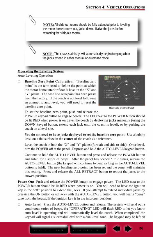
59
Section 4: Vehicle Operations
Operating the Leveling SystemAuto Leveling Operation
Baseline Zero Point Calibration: “Baseline zero point” is the term used to define the point at which the motor home interior floor is level in the “X” and “Y” plains. The base line zero point has been preset from the factory. If the coach is not level following an attempt to auto level, you will need to reset the baseline zero point.To set the baseline zero point, push and release the POWER keypad button to engage power. The LED next to the POWER button should be lit RED when power is on.Level the coach by deploying jacks manually (using the DOWN keypad button, extend each jack until the coach is level), or by parking the coach on a level site.
You do not need to have jacks deployed to set the baseline zero point. Use a bubble level on a flat surface in the center of the coach as a reference.
Level the coach in both the “X” and “Y” plains (fore-aft and side to side). Once level, turn the POWER off at the panel. Depress and hold the AUTO-LEVEL keypad button.
Continue to hold the AUTO-LEVEL button and press and release the POWER button and listen for a series of beeps. After the panel has beeped 5 to 6 times, release the AUTO-LEVEL button (the keypad will continue to beep as long as the AUTO-LEVEL button is held). The new baseline zero point has been set and the panel will maintain this setting. Press and release the ALL RETRACT button to retract the jacks to the stowed position.
Power On: Push and release the POWER button to engage power. The LED next to the POWER button should be lit RED when power is on. You will need to have the ignition key in the “off” position to extend the jacks. If you attempt to extend individual jacks by pressing the ON button or all jacks with the AUTO-LEVEL button, you will hear a “deny” tone from the keypad if the ignition key is in the improper position.
Auto Level: Press the AUTO-LEVEL button and release. The system will send out a continuous series of beeps, the “OPERATING” LED will flash RED to let you know auto level is operating and will automatically level the coach. When completed, the keypad will signal a successful level with a dual-level tone. The keypad may be left on
Hydraulic Control Panel
NOTE: All slide-out rooms should be fully extended prior to leveling the motor home; rooms out, jacks down. Raise the jacks before retracting the slide-out rooms.
NOTE: The chassis air bags will automatically begin dumping when the jacks extend in either manual or automatic mode.
60
Section 4: Vehicle Operations
once level has been achieved. The keypad will enter “sleep mode” after five minutes of inactivity.
Retracting the Jacks: The Equalizer System provides the ability to retract the jacks using the ALL RETRACT button or the UP button for each individual jack.All jacks will automatically retract and return to stowed position when the ALL RETRACT button is pressed and released. The pump will run in retract mode for 60 seconds (or 90) to ensure the jacks are fully stowed. You may allow the system to run for the entire programmed time and stop automatically, or you may stop the ALL RETRACT by pressing any button on the keypad.
Manual OperationPower on: Push and release the POWER keypad button to engage power. The LED next to the POWER button should be lit RED when power is on. If you attempt to extend individual jacks by pressing the DOWN keypad button or all jacks with the AUTO-LEVEL button, you will hear a “deny” tone from the keypad if the ignition key is in the improper position.
Planting the Jacks: Using the DOWN keypad button, extend each jack until they contact the ground (this is referred to as “planting” the jacks).As you extend the jacks, the LED lights on the keypad will indicate the jacks are out of the “stowed” position. Jacks may be operated individually or in pairs.
Do not manually overextend individual jacks. This may cause unwanted stress on the coach or the jacks.
Leveling the Coach: Use a bubble level in the center of the coach as a reference. Level the vehicle by using DOWN or UP keypad buttons until the vehicle is level. Jacks may be operated individually or in pairs as long as they are operated in the same direction.Do not attempt to lift the vehicle off of the tires. The keypad may be left “on” once level has been achieved. The keypad will enter “sleep mode” after five minutes of inactivity.
Retracting the Jacks: The Equalizer System provides the ability to retract the jacks using the ALL RETRACT button or the UP button for each individual jack. All jacks will automatically retract and return to stowed position when the ALL RETRACT button is pressed and released.
The pump will run in retract mode until all of the jacks are fully stowed (plus an additional 5 seconds) up to a maximum of 60 seconds. You may stop the ALL RETRACT by pressing any button on the keypad. Your coach is equipped with air suspension, and it is recommended that you start your coach before pressing ALL RETRACT allowing the chassis air to build. This will ensure adequate air supply to the chassis air valves.
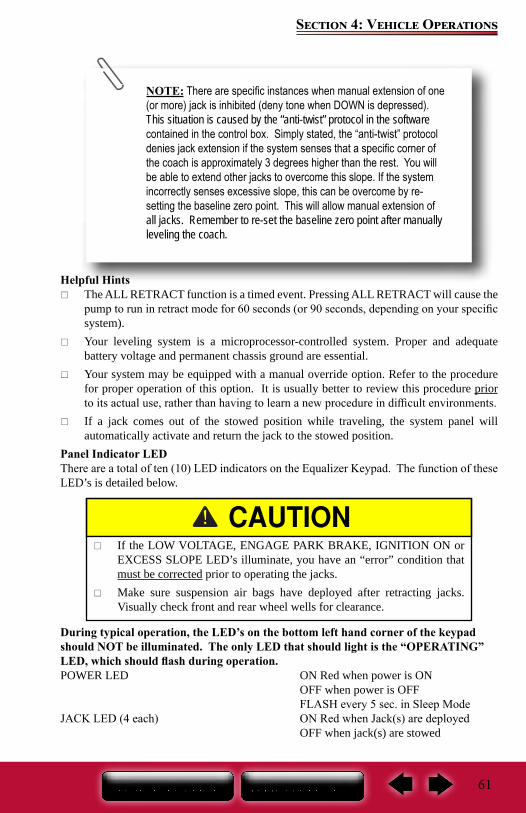
61
Section 4: Vehicle Operations
Helpful Hints The ALL RETRACT function is a timed event. Pressing ALL RETRACT will cause the
pump to run in retract mode for 60 seconds (or 90 seconds, depending on your specific system).
Your leveling system is a microprocessor-controlled system. Proper and adequate battery voltage and permanent chassis ground are essential.
Your system may be equipped with a manual override option. Refer to the procedure for proper operation of this option. It is usually better to review this procedure prior to its actual use, rather than having to learn a new procedure in difficult environments.
If a jack comes out of the stowed position while traveling, the system panel will automatically activate and return the jack to the stowed position.
Panel Indicator LEDThere are a total of ten (10) LED indicators on the Equalizer Keypad. The function of these LED’s is detailed below.
During typical operation, the LED’s on the bottom left hand corner of the keypad should NOT be illuminated. The only LED that should light is the “OPERATING” LED, which should flash during operation.POWER LED ON Red when power is ON OFF when power is OFF FLASH every 5 sec. in Sleep ModeJACK LED (4 each) ON Red when Jack(s) are deployed OFF when jack(s) are stowed
NOTE: There are specific instances when manual extension of one (or more) jack is inhibited (deny tone when DOWN is depressed). This situation is caused by the “anti-twist” protocol in the software contained in the control box. Simply stated, the “anti-twist” protocol denies jack extension if the system senses that a specific corner of the coach is approximately 3 degrees higher than the rest. You will be able to extend other jacks to overcome this slope. If the system incorrectly senses excessive slope, this can be overcome by re-setting the baseline zero point. This will allow manual extension of all jacks. Remember to re-set the baseline zero point after manually leveling the coach.
If the LOW VOLTAGE, ENGAGE PARK BRAKE, IGNITION ON or EXCESS SLOPE LED’s illuminate, you have an “error” condition that must be corrected prior to operating the jacks.
Make sure suspension air bags have deployed after retracting jacks. Visually check front and rear wheel wells for clearance.
62
Section 4: Vehicle Operations
OPERATING LED FLASHING Red w/Auto Level or All Retract OFF when keypad is idle or “sleeping”LOW VOLTAGE LED ON Red when voltage is below 10.5 volts dc OFF when voltage is above 10.5 volts dcENGAGE PARK BRAKE LED ON Red when park brake is not set OFF when park brake is setIGNITION ON LED ON Red when ignition is in the ON position OFF when ignition is OFFEXCESS SLOPE LED ON Red following an Auto Level attempt, if system cannot overcome slope OFF when slope is not excessive
Emergency StoppingAlways carry road flares or reflective warning signs. Pull off the roadway as far as possible for emergency stopping. Turn ON your vehicle hazard warning flashers. If traveling at night, use three red warning indicators such as flares, reflectors or lanterns as required by the Uniform Vehicle Code and Model Traffic Ordinance as follows:
1. Place the first warning indicator on the traffic side of the recreation vehicle, directed at the nearest approaching traffic.
2. Place the second warning indicator 100 feet behind the recreation vehicle in the center of the lane and toward approaching traffic.
3. Place the third warning indicator 100 feet in front of the recreation vehicle in the center of the lane and away from the traffic approaching from behind.
NOTE: Curves and/or hills may affect the safe placement of warn-ing indicators.
DO NOT USE THE STABILIZER JACKS TO LEVEL THE RV. It is important to remember that the stabilizer jacks are to be used only for support while occupying and moving around the RV. They are not designed to support the weight of the RV.
Emergency TowingIf your motor home ever needs to be towed, refer to the instructions in your Chassis Guide. Please contact your road service provider (if applicable) or a qualified service facility for assistance.
Make sure the road service technician reads and is familiar with the information contained in your Chassis Guide regarding emergency towing.
63
Section 4: Vehicle Operations
Never allow anyone to go under the motor home while it is being lifted by towing equipment.
When the unit is being towed, be aware of the strap locations. Misplaced straps could result in damage to the exterior of your unit. Damage resulting from misplaced straps is the responsibility of the towing company, and is not covered by the unit warranty.
Front Axle Tire AlignmentThe term alignment refers to both the adjustment angles on the steering axle and suspension and tracking of the rear axle. Steering components, suspension, wheel bearings and even proper loading will affect the alignment.
We recommend you have the front suspension and steering alignment checked and adjusted after you have fully loaded the vehicle according to your needs as part of the vehicle maintenance. Thereafter, it is your responsibility to have the alignment inspected periodically to maintain vehicle steering performance and prevent uneven tire wear as part of your normal maintenance.
After this road test has been completed, front-end alignment and/or vibrations will not be covered as part of the new vehicle limited warranty.
Follow the Chassis Guide maintenance instructions for the front and rear axle for wheel and suspension maintenance, including the brakes and wheel bearings. Contact your Chassis manufacturer for assistance.
NOTE: Always have the alignment checked and adjusted by a qualified shop with the proper equipment to handle heavy vehicles.
NOTE: A road test by the dealer should be included as part of the pre-delivery inspection. The dealer can check for and correct any steering problems before you take delivery.
64
Section 4: Vehicle Operations
Wheel Lug Nuts/Wheel Liners
Torque is the amount of rotating force applied to a lug nut, and can only be achieved by using a properly calibrated torque wrench and socket. Do not use a 4-way socket or any other type of wrench that does not measure the actual pressure applied to the lug nut.
After your first trip, check the wheel lug torque periodically for safety according to your Chassis Guide. If you suspect the wheel lug nuts have loosened at any time, have them checked and torqued to the proper limits immediately.
Check and re-torque after the first 10, 25 and 50 miles (16, 40 and 80 kilometers). Thereafter, check and maintain the torque according to the listed torque values.Wheel lugsIf you suspect or notice the wheel stud bolts are cracked or broken, they must be replaced, along with adjacent bolts that have probably also been weakened due to the additional stress placed on them.
Aluminum Wheels (if so equipped)Clean the aluminum wheels with a cleaner that is designed for use on aluminum and apply an appropriate protection agent. Do not use abrasive cleaners. Wheels exposed to sea water or road chemicals should be cleaned as soon as possible. Be sure to use a sponge or chamois leather (brushes may damage the aluminum wheel surface.)
Check and tighten the wheel lug nuts regularly to make sure they did not loosen during travel. Refer to your Chassis Guide for torque recommendations.
Failure to tighten and maintain wheel lug nuts to the proper torque specification, could allow the wheels to come off while driving, resulting in serious injury or property damage in the event of a collision or loss of vehicle control.
NOTE: The proper method of tightening wheel lug nuts is with a torque wrench, not with an impact wrench or by hand. Because of the importance of having proper torque on the wheel lug nuts, you should always have the wheels mounted and properly torqued by a qualified technician using the proper tools.
NOTE: If your motor home is equipped with aluminum wheels, only the outer dual wheels are aluminum, the inner duals are steel wheels.
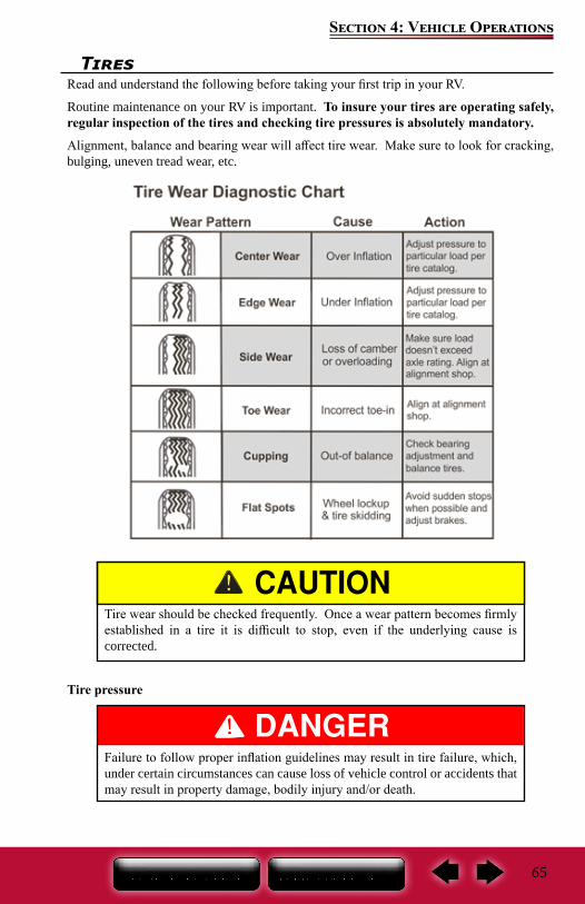
65
Section 4: Vehicle Operations
TiresRead and understand the following before taking your first trip in your RV.
Routine maintenance on your RV is important. To insure your tires are operating safely, regular inspection of the tires and checking tire pressures is absolutely mandatory.
Alignment, balance and bearing wear will affect tire wear. Make sure to look for cracking, bulging, uneven tread wear, etc.
Tire pressure
Tire wear should be checked frequently. Once a wear pattern becomes firmly established in a tire it is difficult to stop, even if the underlying cause is corrected.
Failure to follow proper inflation guidelines may result in tire failure, which, under certain circumstances can cause loss of vehicle control or accidents that may result in property damage, bodily injury and/or death.
66
Section 4: Vehicle Operations
You must follow the manufacturer’s inflation guidelines for maximum load capacity; under-inflation is just as dangerous as over-inflation.Proper inflation should be monitored closely. Failure to do so could result in the overheating of a tire causing a blowout. Inflation pressure should be as recommended by the tire manufacturer or as the federal label for the recreation vehicle indicates.
When you are using your Recreational Vehicle, check inflation pressure weekly. Pressure should be checked when the tires are cold. During travel, tires heat up and pressure increases. Do not bleed air from hot tires or your tires may then be under-inflated.
It is recommended that the tire pressure be checked at the beginning of each trip to obtain the maximum life of the tire. Follow the instructions listed on the Federal Certification label, to determine the correct tire pressure. Under-inflation may cause tire failures and swaying resulting in loss of control, injury, death or property damage.
TOWABLE PRODUCTS ONLY Towable recreation vehicles are equipped with special trailer (ST) tires
that have a maximum speed rating of 65 MPH (104 km/h). You should not exceed this speed rating. Exceeding the tire speed rating may result in tire failure, which could lead to an accident causing serious injury or death.
NOTE: Cold tire inflation pressure is defined as a tire that has not been used for three or more hours, or has been driven less than one mile. Tire inflation pressure of a hot tire may show an increase of as much as 6 psi over a cold tire.
67
Section 4: Vehicle Operations
Changing A Tire
If you experience a flat tire on your motor home while driving, gradually decrease your vehicle speed (if possible), and move the motor home to a safe place on the side of the road. Contact your road service provider (if applicable) or a qualified service facility for assistance. Do not attempt to change the tire or jack the motor home up yourself; this is why a jack and a spare tire have not been included with the motor home.
Make sure the road service technician reads and is familiar with the Chassis Guide information regarding changing the tires. Make sure the wheel lug nuts have been tightened to the proper torque as outlined in your Chassis Guide.
The motor home is very heavy. Raising the motor home to replace the spare tire should only be done with extreme caution by a qualified technician. The vehicle could slip, causing personal injury or death. DO NOT ATTEMPT TO DO THIS YOURSELF.
Do not use the hydraulic leveling jack system to support the motor home while under the vehicle or changing tires. The hydraulic leveling system is designed as a leveling system only. Do not use the hydraulic leveling jack system as a jack or in conjunction with a jack. It is highly recommended that, should a tire change be required, it be performed by a knowledgeable, trained professional. Attempts to change tires while supporting the motor home with the hydraulic leveling jack system could result in damage to the motor home and risk causing serious injury or death.
When replacing a tire, make sure to replace it with a tire of the same size and specifications (refer to your Chassis Guide for assistance.)
Awnings (if so equipped)
Awning CareKeep your awnings clean and in good condition to prevent costly repairs.
Periodically check that the fasteners are tight. Tighten if necessary.
Awnings must be closed (and locked if applicable) while the RV is in transit.
The effects of wind and rain on an awning are unpredictable and can cause severe damage to the awning and/or the recreation vehicle. Retract the awning if:
If wind or extended periods of rain are expected If you leave the RV unattended for a length of time, to avoid unexpected
climate conditions.
68
Section 4: Vehicle Operations
NOTE: The electric awning requires connection to a 120-volt power source. Make sure you have sufficient power available before operating your awning (refer Electrical Systems, Calculating electrical load).
Keep the awning fabric clean. For detailed cleaning information, refer to the manufacturer’s owner information.
Your recreation vehicle may include one or more of the following options:
Power window awnings Slide out awnings Power awning over entrance door
Power switches to operate the awnings are typically found in the control panel above the entrance door.
Electric Patio Awning With Remote ControlIn Motion Detector (if so equipped)
Some patio awnings are equipped with a motion detector. If the patio awning experiences extreme or excessive movement, it will automatically retract to the travel mode position.
For detailed safety and operating information, refer to the manufacturer’s user guide.
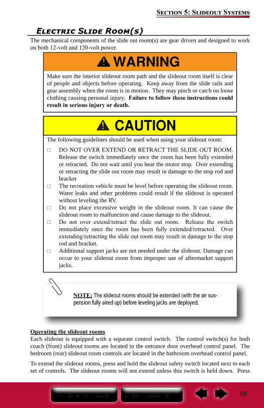
69
Section 5: Slideout Systems
Electric Slide Room(s)The mechanical components of the slide out room(s) are gear driven and designed to work on both 12-volt and 120-volt power.
Operating the slideout roomsEach slideout is equipped with a separate control switch. The control switch(s) for both coach (front) slideout rooms are located in the entrance door overhead control panel. The bedroom (rear) slideout room controls are located in the bathroom overhead control panel.
To extend the slideout rooms, press and hold the slideout safety switch located next to each set of controls. The slideout rooms will not extend unless this switch is held down. Press
The following guidelines should be used when using your slideout room:
DO NOT OVER EXTEND OR RETRACT THE SLIDE OUT ROOM. Release the switch immediately once the room has been fully extended or retracted. Do not wait until you hear the motor stop. Over extending or retracting the slide out room may result in damage to the stop rod and bracket
The recreation vehicle must be level before operating the slideout room. Water leaks and other problems could result if the slideout is operated without leveling the RV.
Do not place excessive weight in the slideout room. It can cause the slideout room to malfunction and cause damage to the slideout.
Do not over extend/retract the slide out room. Release the switch immediately once the room has been fully extended/retracted. Over extending/retracting the slide out room may result in damage to the stop rod and bracket.
Additional support jacks are not needed under the slideout. Damage can occur to your slideout room from improper use of aftermarket support jacks.
Make sure the interior slideout room path and the slideout room itself is clear of people and objects before operating. Keep away from the slide rails and gear assembly when the room is in motion. They may pinch or catch on loose clothing causing personal injury. Failure to follow these instructions could result in serious injury or death.
NOTE: The slideout rooms should be extended (with the air sus-pension fully aired up) before leveling jacks are deployed.
70
Section 5: Slideout Systems
the control switch of the slideout room you want to extend. The slideout room will stop on its own when fully extended. Press the control switch again to reverse the process. Pressing the control switch while the slideout room is in motion will stop the slideout room from extending.
If the slideout rooms will not extend or retract, contact Entegra Coach Customer Service at 1-800-517-9137, or contact a reputable dealer service facility. If it is after normal business hours, contact Coach Net for assistance. Do not attempt to service the slideout system yourself.
71
Section 6: Electrical System
The Electrical System The RV electrical system is comprised of two independent electrical systems. One operates off of 12-volt DC power and the other off of 120-volt 60hz AC power. All installations have been made in compliance with industry standards applicable on the date of manufacture. Because the electrical equipment and associated circuitry are engineered into a dedicated system specific to your RV, do not make unauthorized changes or add fixed appliances to it. Changes or additions made after delivery may result in a hazardous condition.
Service and/or modification of the electrical system should only be performed by qualified electrical technicians using approved materials, components, and methods meeting current safety and code requirements. Consult your dealer’s service department for assistance.
To read more about the various components incorporated into the RV electrical system, please refer to the information contained in your Warranty Packet.
For motorized vehicles, consult the Chassis Guide for information pertaining to the chassis drivetrain electrical system.
Electrical System MaintenanceBefore working on the electrical system:
Make sure the inverter/charger (if so equipped) is turned “off” before disconnecting batteries.Disconnect the shore power cord.
If equipped with a generator, turn off the generator and disable the automatic generator start functionality (if so equipped).
Turn off the battery disconnect switch (if so equipped) Turn off the 120V main circuit breaker. Disconnect the negative 12VDC battery terminal from the battery.
Use caution when using metal tools. If a tool contacts a battery terminal or metal connected to it, a short circuit could occur which could cause personal injury, explosion or fire.
In Case Of An Electrical Fire
HAVE EVERYONE EVACUATE THE RECREATION VEHICLE IMMEDIATELY. Switch the 120-volt main circuit breaker to the “off” position. It is important that
everyone knows where to find the main circuit breaker and how it operates. Disconnect the negative battery cable(s) at the battery. Disconnect the power cord from the shore power receptacle. Turn “off” the generator (if so equipped).
Always have faulty or damaged wiring and electrical components repaired immediately.
Do not attempt to use water to put out an electrical fire. Water can spread some types of fire, and electrocution is possible with an electrical fire.
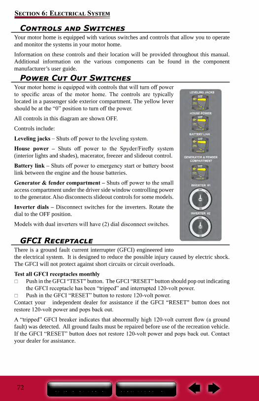
72
Section 6: Electrical System
Power Cut Out SwitchesYour motor home is equipped with controls that will turn off power to specific areas of the motor home. The controls are typically located in a passenger side exterior compartment. The yellow lever should be at the “0” position to turn off the power.
All controls in this diagram are shown OFF.
Controls include:
Leveling jacks – Shuts off power to the leveling system.
House power – Shuts off power to the Spyder/Firefly system (interior lights and shades), macerator, freezer and slideout control.
Battery link – Shuts off power to emergency start or battery boost link between the engine and the house batteries.
Generator & fender compartment – Shuts off power to the small access compartment under the driver side window controlling power to the generator. Also disconnects slideout controls for some models.
Inverter dials – Disconnect switches for the inverters. Rotate the dial to the OFF position.
Models with dual inverters will have (2) dial disconnect switches.
GFCI ReceptacleThere is a ground fault current interrupter (GFCI) engineered into the electrical system. It is designed to reduce the possible injury caused by electric shock. The GFCI will not protect against short circuits or circuit overloads.
Test all GFCI receptacles monthly Push in the GFCI “TEST” button. The GFCI “RESET” button should pop out indicating
the GFCI receptacle has been “tripped” and interrupted 120-volt power. Push in the GFCI “RESET” button to restore 120-volt power.
Contact your independent dealer for assistance if the GFCI “RESET” button does not restore 120-volt power and pops back out.
A “tripped” GFCI breaker indicates that abnormally high 120-volt current flow (a ground fault) was detected. All ground faults must be repaired before use of the recreation vehicle. If the GFCI “RESET” button does not restore 120-volt power and pops back out. Contact your dealer for assistance.
Controls and SwitchesYour motor home is equipped with various switches and controls that allow you to operate and monitor the systems in your motor home.
Information on these controls and their location will be provided throughout this manual. Additional information on the various components can be found in the component manufacturer’s user guide.
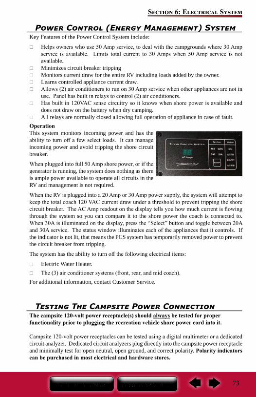
73
Section 6: Electrical System
Power Control (Energy Management) System Key Features of the Power Control System include:
Helps owners who use 50 Amp service, to deal with the campgrounds where 30 Amp service is available. Limits total current to 30 Amps when 50 Amp service is not available.
Minimizes circuit breaker tripping Monitors current draw for the entire RV including loads added by the owner. Learns controlled appliance current draw. Allows (2) air conditioners to run on 30 Amp service when other appliances are not in
use. Panel has built in relays to control (2) air conditioners. Has built in 120VAC sense circuitry so it knows when shore power is available and
does not draw on the battery when dry camping. All relays are normally closed allowing full operation of appliance in case of fault.
OperationThis system monitors incoming power and has the ability to turn off a few select loads. It can manage incoming power and avoid tripping the shore circuit breaker.
When plugged into full 50 Amp shore power, or if the generator is running, the system does nothing as there is ample power available to operate all circuits in the RV and management is not required.
When the RV is plugged into a 20 Amp or 30 Amp power supply, the system will attempt to keep the total coach 120 VAC current draw under a threshold to prevent tripping the shore circuit breaker. The AC Amp readout on the display tells you how much current is flowing through the system so you can compare it to the shore power the coach is connected to. When 30A is illuminated on the display, press the “Select” button and toggle between 20A and 30A service. The status window illuminates each of the appliances that it controls. If the indicator is not lit, that means the PCS system has temporarily removed power to prevent the circuit breaker from tripping.
The system has the ability to turn off the following electrical items:
Electric Water Heater. The (3) air conditioner systems (front, rear, and mid coach).
For additional information, contact Customer Service.
Testing The Campsite Power ConnectionThe campsite 120-volt power receptacle(s) should always be tested for proper functionality prior to plugging the recreation vehicle shore power cord into it.
Campsite 120-volt power receptacles can be tested using a digital multimeter or a dedicated circuit analyzer. Dedicated circuit analyzers plug directly into the campsite power receptacle and minimally test for open neutral, open ground, and correct polarity. Polarity indicators can be purchased in most electrical and hardware stores.
74
Section 6: Electrical System
Do not hook up the power cord to any receptacle until you have verified proper polarity and grounding.
DO NOT plug the shore power cord into a campsite receptacle(s):
That has reverse polarity With non-functioning ground circuits That shows outward signs of heat damage. Doing so may result in property damage or serious injury. Plugging
the shoreline power cord into an incorrectly wired power source could damage the recreation vehicle electrical system and result in severe or fatal injury. Damage or injury resulting from connection to malfunctioning or improperly wired power sources is not covered by your recreation vehicle warranty.
DO NOT
Do not use any cheater plug, adapter or extension cord to reconfigure incoming AC power or break the continuity of the circuit connected to the grounding pin.
Do not connect the power cord into an outlet that is not grounded, or adapt the power cord plug to connect it to a receptacle for which it is not designed.
Do not remove the grounding pin to connect to a non-grounded receptacle. Removal of the ground pin disables an important safety feature designed to prevent shock and electrocution hazards.
Do not connect the power cord to an extension cord. Use of an improper extension cord will cause overheating of the cord as well as potentially causing premature failure of the AC equipment.
The power cord must be fully extended when in use and not left coiled in the electrical compartment or on the ground. If the power cord is left coiled, it may potentially create enough heat to melt its protective casing.
It is the responsibility of the owner of the electrical receptacle to ensure that the receptacle is properly wired and grounded. Reverse polarity and/or improper grounding of your RV can cause property damage or serious personal injury.
Connecting The Power CordAlways test the external power source (i.e., the campsite power receptacle or electrical box) with a ground monitor before connecting your power cord to it. If the ground monitor indicates ‘reverse polarity’ or an ‘open ground’ DO NOT connect the power cord.
To help prevent power surges from damaging the connected loads, please follow these instructions when hooking up to the external power source:
1. Turn “off” the load center main 120-volt circuit breaker.2. Carefully extend the entire length of the power cord (approximately 25’-35’) from the
electric cable hatch to the external power source.3. Plug the power cord into the receptacle. Be sure all the power cord prongs are properly
plugged into the receptacle.
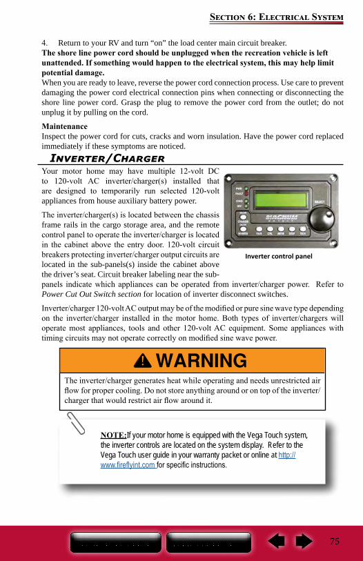
75
Section 6: Electrical System
4. Return to your RV and turn “on” the load center main circuit breaker.The shore line power cord should be unplugged when the recreation vehicle is left unattended. If something would happen to the electrical system, this may help limit potential damage.When you are ready to leave, reverse the power cord connection process. Use care to prevent damaging the power cord electrical connection pins when connecting or disconnecting the shore line power cord. Grasp the plug to remove the power cord from the outlet; do not unplug it by pulling on the cord.
MaintenanceInspect the power cord for cuts, cracks and worn insulation. Have the power cord replaced immediately if these symptoms are noticed.
Inverter/ChargerYour motor home may have multiple 12-volt DC to 120-volt AC inverter/charger(s) installed that are designed to temporarily run selected 120-volt appliances from house auxiliary battery power.
The inverter/charger(s) is located between the chassis frame rails in the cargo storage area, and the remote control panel to operate the inverter/charger is located in the cabinet above the entry door. 120-volt circuit breakers protecting inverter/charger output circuits are located in the sub-panels(s) inside the cabinet above the driver’s seat. Circuit breaker labeling near the sub-panels indicate which appliances can be operated from inverter/charger power. Refer to Power Cut Out Switch section for location of inverter disconnect switches.
Inverter/charger 120-volt AC output may be of the modified or pure sine wave type depending on the inverter/charger installed in the motor home. Both types of inverter/chargers will operate most appliances, tools and other 120-volt AC equipment. Some appliances with timing circuits may not operate correctly on modified sine wave power.
The inverter/charger generates heat while operating and needs unrestricted air flow for proper cooling. Do not store anything around or on top of the inverter/charger that would restrict air flow around it.
NOTE:If your motor home is equipped with the Vega Touch system, the inverter controls are located on the system display. Refer to the Vega Touch user guide in your warranty packet or online at http://www.fireflyint.com for specific instructions.
Inverter control panel
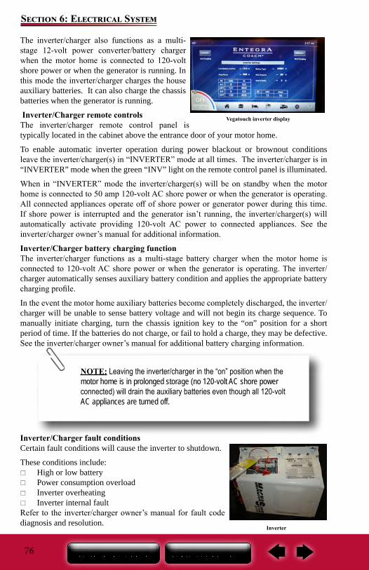
76
Section 6: Electrical System
Vegatouch inverter display
The inverter/charger also functions as a multi-stage 12-volt power converter/battery charger when the motor home is connected to 120-volt shore power or when the generator is running. In this mode the inverter/charger charges the house auxiliary batteries. It can also charge the chassis batteries when the generator is running.
Inverter/Charger remote controlsThe inverter/charger remote control panel is typically located in the cabinet above the entrance door of your motor home.
To enable automatic inverter operation during power blackout or brownout conditions leave the inverter/charger(s) in “INVERTER” mode at all times. The inverter/charger is in “INVERTER” mode when the green “INV” light on the remote control panel is illuminated.
When in “INVERTER” mode the inverter/charger(s) will be on standby when the motor home is connected to 50 amp 120-volt AC shore power or when the generator is operating. All connected appliances operate off of shore power or generator power during this time. If shore power is interrupted and the generator isn’t running, the inverter/charger(s) will automatically activate providing 120-volt AC power to connected appliances. See the inverter/charger owner’s manual for additional information.
Inverter/Charger battery charging functionThe inverter/charger functions as a multi-stage battery charger when the motor home is connected to 120-volt AC shore power or when the generator is operating. The inverter/charger automatically senses auxiliary battery condition and applies the appropriate battery charging profile.
In the event the motor home auxiliary batteries become completely discharged, the inverter/charger will be unable to sense battery voltage and will not begin its charge sequence. To manually initiate charging, turn the chassis ignition key to the “on” position for a short period of time. If the batteries do not charge, or fail to hold a charge, they may be defective. See the inverter/charger owner’s manual for additional battery charging information.
Inverter/Charger fault conditionsCertain fault conditions will cause the inverter to shutdown.
These conditions include: High or low battery Power consumption overload Inverter overheating Inverter internal fault
Refer to the inverter/charger owner’s manual for fault code diagnosis and resolution.
Inverter
NOTE: Leaving the inverter/charger in the “on” position when the motor home is in prolonged storage (no 120-volt AC shore power connected) will drain the auxiliary batteries even though all 120-volt AC appliances are turned off.
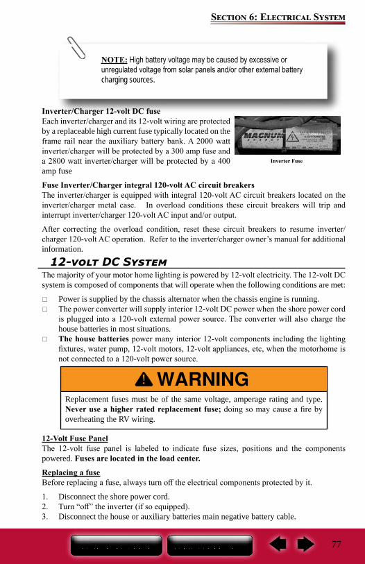
77
Section 6: Electrical System
12-volt DC System The majority of your motor home lighting is powered by 12-volt electricity. The 12-volt DC system is composed of components that will operate when the following conditions are met:
Power is supplied by the chassis alternator when the chassis engine is running. The power converter will supply interior 12-volt DC power when the shore power cord
is plugged into a 120-volt external power source. The converter will also charge the house batteries in most situations.
The house batteries power many interior 12-volt components including the lighting fixtures, water pump, 12-volt motors, 12-volt appliances, etc, when the motorhome is not connected to a 120-volt power source.
12-Volt Fuse PanelThe 12-volt fuse panel is labeled to indicate fuse sizes, positions and the components powered. Fuses are located in the load center.
Replacing a fuseBefore replacing a fuse, always turn off the electrical components protected by it.
1. Disconnect the shore power cord. 2. Turn “off” the inverter (if so equipped).3. Disconnect the house or auxiliary batteries main negative battery cable.
Replacement fuses must be of the same voltage, amperage rating and type. Never use a higher rated replacement fuse; doing so may cause a fire by overheating the RV wiring.
Inverter/Charger 12-volt DC fuseEach inverter/charger and its 12-volt wiring are protected by a replaceable high current fuse typically located on the frame rail near the auxiliary battery bank. A 2000 watt inverter/charger will be protected by a 300 amp fuse and a 2800 watt inverter/charger will be protected by a 400 amp fuse
Fuse Inverter/Charger integral 120-volt AC circuit breakersThe inverter/charger is equipped with integral 120-volt AC circuit breakers located on the inverter/charger metal case. In overload conditions these circuit breakers will trip and interrupt inverter/charger 120-volt AC input and/or output.
After correcting the overload condition, reset these circuit breakers to resume inverter/charger 120-volt AC operation. Refer to the inverter/charger owner’s manual for additional information.
NOTE: High battery voltage may be caused by excessive or unregulated voltage from solar panels and/or other external battery charging sources.
Inverter Fuse
78
Section 6: Electrical System
Keep the protective dust cap on the 12-volt DC outlet when not in use to prevent ingestion of foreign material and potential short circuit conditions.
4. Remove the fuse panel cover to check fuses.5. Pull the fuse straight out of the fuse block. 6. Insert a new fuse of the same specified voltage, amperage rating and type in the original
location. The fuse panel label should be kept permanently affixed to your recreation vehicle. Fuses will not offer complete protection of the electrical system in the event of a power surge or spike.
12-Volt DC OutletThere may be one or more 12-volt DC power outlets in your recreation vehicle. When the 12-volt DC outlet is used as a power source for an electric appliance, make sure the appliance operates on 12-volt DC power and that it consumes less than 60 watts (5 amps) of power.
79
Section 6: Electrical System
Batteries
House BatteriesYour motor home is equipped with heavy-duty deep cycle or absorbed glass mat (AGM) batteries.
Unless a battery has been fully discharged, house auxiliary batteries are normally charged in one of two ways:
When the power cord is plugged into 120-volt shore power, or when the generator is operational, the inverter/charger functions as a multi-stage battery charger and will automatically charge the house auxiliary batteries when required. A bi-directional charge relay incorporated into the electrical system allows the inverter/charger to charge the chassis batteries once the house auxiliary batteries are sufficiently charged.
The chassis alternator charging system supplies power to the house auxiliary batteries when the engine is running and the chassis batteries are sufficiently charged.
See the Chassis Guide for information pertaining to the chassis batteries and the drivetrain electrical system.House auxiliary battery voltage can be checked using the inverter/charger remote control panel located in the cabinet above the entrance door of your motor home.
A fully charged battery will read 12.65 volts DC with a specific gravity of 1.265 at 80°F (32°C). A battery is considered discharged at 11.89 volts DC or when it has a specific gravity of 1.120 or less. When voltage drops to 11.89 volts, irreversible battery damage can occur.
Dry CampingHouse auxiliary and chassis batteries should be fully charged prior to dry camping. When
Do not store anything inside the battery compartment(s) or near the batteries that could touch the battery or battery cable terminals. Contact with the battery or battery cable terminals could cause an electrical short circuit, discharge the batteries, or start an electrical fire.
Keep sparks, cigarettes and flames away from the batteries as the hydrogen gas they create may explode. Do not connect a booster battery or other power source that outputs more than 14.2-volts DC to the motor home batteries. Use adequate ventilation when charging or using batteries in an enclosed space.
Remove metal jewelry and always wear eye protection when working around batteries.
Do not allow battery electrolyte (acid) to come into contact with skin, eyes, fabric or painted surfaces. Electrolyte is a sulfuric acid solution that could cause serious personal injury or property damage. If your hands, eyes, clothes or the painted surface of your motor home are exposed to electrolyte, flush the exposed area thoroughly with water. If electrolyte gets in your eyes, immediately flush them thoroughly with water and get prompt medical attention.
Make sure the inverter/charger is turned “off” before disconnecting the negative battery cable from the battery bank. Keep the batteries out of the reach of children.
80
Section 6: Electrical System
disconnected from 120-volt shore or generator power (i.e., while dry camping or tailgating) all electrically operated appliances and accessories must be used sparingly. During this period these appliances and accessories are being powered by the house auxiliary batteries directly, and/or indirectly through the inverter/charger.
If excessive amounts of power are drawn from the house auxiliary batteries, either as small applied loads over an extended period of time or as high applied loads for a short period of time, they will become deeply discharged. Permanent battery damage will occur after repeated deep discharge cycles.
Battery Reserve CapacityTypically, a four battery bank of 6-volt CG-2 deep cycle batteries connected in a series/parallel arrangement to create 12-volts, has a 75 amp discharge rate reserve capacity (RC) rating of around 420 minutes.
This same house auxiliary battery bank will have a 25 amp discharge rate reserve capacity (RC) rating of around 1530 minutes. If your motor home has an eight battery bank of 6-volt CG-2 deep cycle batteries, the reserve capacity minutes listed above are doubled.
General usage information (using estimated ratings)If you have 15 each 12-volt 20-watt halogen lights (1.67 amps each light x 15 lights = 25.05 amps) operating in your motor home, the four battery bank of batteries would operate those 15 lights by themselves for 1530 minutes (25.5 hours) before the batteries were fully discharged. Likewise, a 12-volt load of 75 amps could be operated for 420 minutes (7.0 hours) before the batteries were fully discharged.
12-volt loads drawn from the battery bank(s) while operating 120-volt appliances through the inverter/charger can approach 300 amps on a single inverter/charger equipped motor home, and 700 amps on a dual inverter/charger equipped motor home. Complete battery discharge will occur quickly when inverter/charger loads are applied.
Batteries discharge at a faster rate the deeper they become discharged. To minimize battery discharge:
When disconnected from 120-volt shore or generator power and not requiring the operation of 120-volt appliances or equipment, turn the inverter/charger remote control panel to the “off” position.
Custom configure your inverter/charger’s remote control panel (see the inverter/charger owner’s manual) to best meet your power usage profile.
Battery Inspection & CareCheck the level of electrolyte in each battery cell once a year. Add distilled water as needed to reach the split-level marker on each battery. Keep batteries and battery terminals clean and tight.
Check the external condition of the batteries periodically. Look for cracks in the cover and case. Make sure battery vent caps are tight and replace them if they are cracked or broken.
Battery storage instructionsTo prevent house auxiliary battery discharge when your motor home will not be connected to shore power for extended periods of time, it is recommended you turn “off” the 12-volt battery disconnect switch, or “main power switch,” and disconnect each battery bank at the negative battery cable running to the chassis frame.
During storage, it is important to check the voltage of your batteries at least monthly using
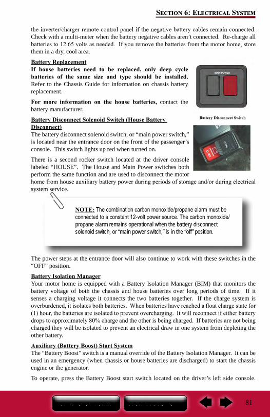
81
Section 6: Electrical System
the inverter/charger remote control panel if the negative battery cables remain connected. Check with a multi-meter when the battery negative cables aren’t connected. Re-charge all batteries to 12.65 volts as needed. If you remove the batteries from the motor home, store them in a dry, cool area.
Battery ReplacementIf house batteries need to be replaced, only deep cycle batteries of the same size and type should be installed. Refer to the Chassis Guide for information on chassis battery replacement.
For more information on the house batteries, contact the battery manufacturer.
Battery Disconnect Solenoid Switch (House Battery Disconnect)The battery disconnect solenoid switch, or “main power switch,” is located near the entrance door on the front of the passenger’s console. This switch lights up red when turned on.
There is a second rocker switch located at the driver console labeled “HOUSE”. The House and Main Power switches both perform the same function and are used to disconnect the motor home from house auxiliary battery power during periods of storage and/or during electrical system service.
The power steps at the entrance door will also continue to work with these switches in the “OFF” position.
Battery Isolation ManagerYour motor home is equipped with a Battery Isolation Manager (BIM) that monitors the battery voltage of both the chassis and house batteries over long periods of time. If it senses a charging voltage it connects the two batteries together. If the charge system is overburdened, it isolates both batteries. When batteries have reached a float charge state for (1) hour, the batteries are isolated to prevent overcharging. It will reconnect if either battery drops to approximately 80% charge and the other is being charged. If batteries are not being charged they will be isolated to prevent an electrical draw in one system from depleting the other battery.
Auxiliary (Battery Boost) Start SystemThe “Battery Boost” switch is a manual override of the Battery Isolation Manager. It can be used in an emergency (when chassis or house batteries are discharged) to start the chassis engine or the generator.
To operate, press the Battery Boost start switch located on the driver’s left side console.
Battery Disconnect Switch
NOTE: The combination carbon monoxide/propane alarm must be connected to a constant 12-volt power source. The carbon monoxide/propane alarm remains operational when the battery disconnect solenoid switch, or “main power switch,” is in the “off” position.
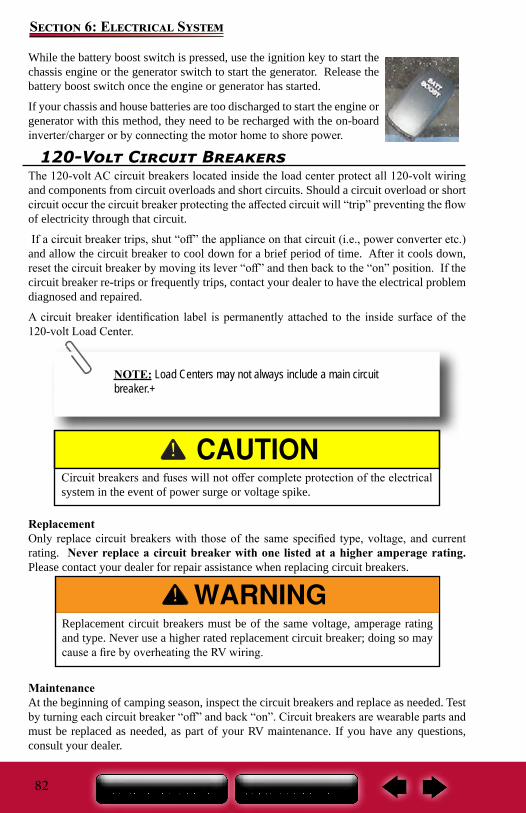
82
Section 6: Electrical System
While the battery boost switch is pressed, use the ignition key to start the chassis engine or the generator switch to start the generator. Release the battery boost switch once the engine or generator has started.
If your chassis and house batteries are too discharged to start the engine or generator with this method, they need to be recharged with the on-board inverter/charger or by connecting the motor home to shore power.
120-Volt Circuit BreakersThe 120-volt AC circuit breakers located inside the load center protect all 120-volt wiring and components from circuit overloads and short circuits. Should a circuit overload or short circuit occur the circuit breaker protecting the affected circuit will “trip” preventing the flow of electricity through that circuit.
If a circuit breaker trips, shut “off” the appliance on that circuit (i.e., power converter etc.) and allow the circuit breaker to cool down for a brief period of time. After it cools down, reset the circuit breaker by moving its lever “off” and then back to the “on” position. If the circuit breaker re-trips or frequently trips, contact your dealer to have the electrical problem diagnosed and repaired.
A circuit breaker identification label is permanently attached to the inside surface of the 120-volt Load Center.
ReplacementOnly replace circuit breakers with those of the same specified type, voltage, and current rating. Never replace a circuit breaker with one listed at a higher amperage rating. Please contact your dealer for repair assistance when replacing circuit breakers.
Maintenance At the beginning of camping season, inspect the circuit breakers and replace as needed. Test by turning each circuit breaker “off” and back “on”. Circuit breakers are wearable parts and must be replaced as needed, as part of your RV maintenance. If you have any questions, consult your dealer.
NOTE: Load Centers may not always include a main circuit breaker.+
Circuit breakers and fuses will not offer complete protection of the electrical system in the event of power surge or voltage spike.
Replacement circuit breakers must be of the same voltage, amperage rating and type. Never use a higher rated replacement circuit breaker; doing so may cause a fire by overheating the RV wiring.
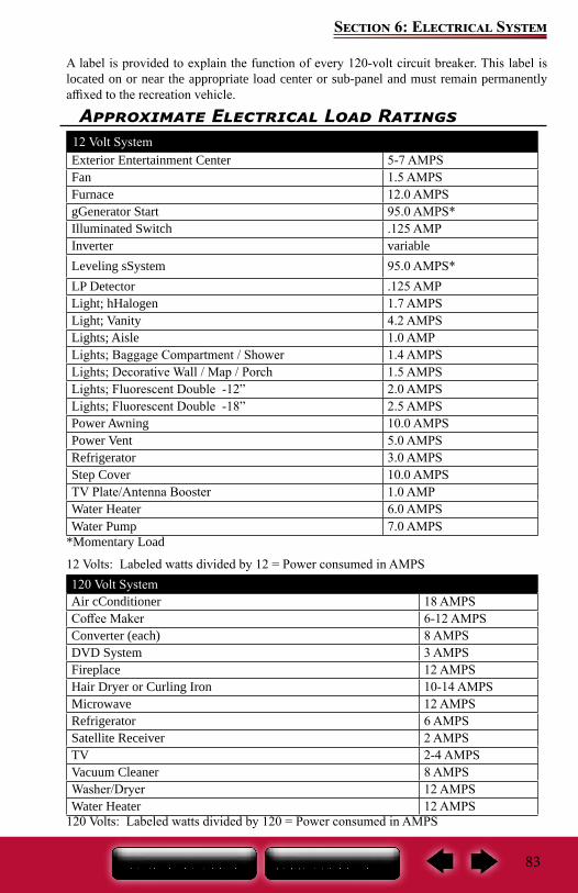
83
Section 6: Electrical System
Approximate Electrical Load Ratings12 Volt SystemExterior Entertainment Center 5-7 AMPSFan 1.5 AMPSFurnace 12.0 AMPSgGenerator Start 95.0 AMPS*Illuminated Switch .125 AMPInverter variableLeveling sSystem 95.0 AMPS*LP Detector .125 AMPLight; hHalogen 1.7 AMPSLight; Vanity 4.2 AMPSLights; Aisle 1.0 AMPLights; Baggage Compartment / Shower 1.4 AMPSLights; Decorative Wall / Map / Porch 1.5 AMPSLights; Fluorescent Double -12” 2.0 AMPSLights; Fluorescent Double -18” 2.5 AMPSPower Awning 10.0 AMPSPower Vent 5.0 AMPSRefrigerator 3.0 AMPSStep Cover 10.0 AMPSTV Plate/Antenna Booster 1.0 AMPWater Heater 6.0 AMPSWater Pump 7.0 AMPS
*Momentary Load
12 Volts: Labeled watts divided by 12 = Power consumed in AMPS120 Volt SystemAir cConditioner 18 AMPSCoffee Maker 6-12 AMPSConverter (each) 8 AMPSDVD System 3 AMPSFireplace 12 AMPSHair Dryer or Curling Iron 10-14 AMPSMicrowave 12 AMPSRefrigerator 6 AMPSSatellite Receiver 2 AMPSTV 2-4 AMPSVacuum Cleaner 8 AMPSWasher/Dryer 12 AMPSWater Heater 12 AMPS
120 Volts: Labeled watts divided by 120 = Power consumed in AMPS
A label is provided to explain the function of every 120-volt circuit breaker. This label is located on or near the appropriate load center or sub-panel and must remain permanently affixed to the recreation vehicle.
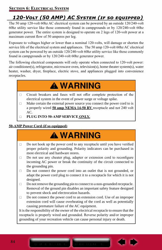
84
Section 6: Electrical System
120-Volt (50 AMP) AC System (if so equipped)The 50 amp 120-volt 60hz AC electrical system can be powered by an outside 120/240-volt 60hz utility service like those commonly found in campgrounds or by 120/240-volt 60hz generator power. The entire system is designed to operate on 2 legs of 120-volt power at a maximum current flow of 50 amperes per leg.
Exposure to voltages higher or lower than a nominal 120-volts, will damage or shorten the service life of the electrical system and appliances. The 50 amp 120-volt 60hz AC electrical system can be powered by an outside 120/240-volt 60hz utility service like those commonly found in campgrounds or by 120/240-volt 60hz generator power.
The following electrical components will only operate when connected to 120-volt power: air conditioner(s), refrigerator, microwave oven, television(s), home theater system(s), water heater, washer, dryer, fireplace, electric stove, and appliances plugged into convenience receptacles.
50-AMP Power Cord (if so equipped)
Do not hook up the power cord to any receptacle until you have verified proper polarity and grounding. Polarity indicators can be purchased in most electrical and hardware stores.
Do not use any cheater plug, adapter or extension cord to reconfigure incoming AC power or break the continuity of the circuit connected to the grounding pin.
Do not connect the power cord into an outlet that is not grounded, or adapt the power cord plug to connect it to a receptacle for which it is not designed.
Do not remove the grounding pin to connect to a non-grounded receptacle. Removal of the ground pin disables an important safety feature designed to prevent shock and electrocution hazards.
Do not connect the power cord to an extension cord. Use of an improper extension cord will cause overheating of the cord as well as potentially causing premature failure of the AC equipment.
It is the responsibility of the owner of the electrical receptacle to ensure that the receptacle is properly wired and grounded. Reverse polarity and/or improper grounding of your recreation vehicle can cause personal injury or death.
Circuit breakers and fuses will not offer complete protection of the electrical system in the event of power surge or voltage spike.
Make certain the external power source you connect the power cord to is a properly wired 50 amp NEMA 14-50 RV receptacle and not 240 volt AC.
PLUG INTO 50-AMP SERVICE ONLY.
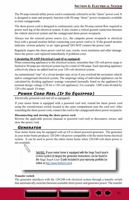
85
Section 6: Electrical System
The 50-amp external utility power cord is commonly referred to as the “shore” power cord. It is designed to mate and properly function with 50-amp “shore” power receptacles available at most campgrounds.
The shore power cord is designed to continuously carry the 50-amp current flow required to power each leg of the electrical system. It also creates a critical ground connection between the vehicle electrical system and the campground shore power receptacle.
Always test the external power source (i.e., the campsite power receptacle or electrical box) with a ground monitor before connecting your power cord to it. If the ground monitor indicates ‘reverse polarity’ or an ‘open ground’ DO NOT connect the power cord.
Regularly inspect the shore power cord for cuts, cracks, worn insulation and other damage. Have the power cord replaced immediately if problems exist.
Calculating 50 AMP Electrical Load (if so equipped)When connecting appliances to the electrical system, remember that 120-volt power usage is limited to 50 amps per electrical system leg for a total of 100 amps. Each operating appliance collectively places an added load on your 120-volt electrical system.
An unintentional “trip” of a circuit breaker may occur if you overload the recreation vehicle and/or campground electrical system. The amperage rating of individual appliances can be calculated by dividing appliance wattage consumed (normally listed on the appliance) by nominal design voltage (120 for a 120-volt appliance). For example: 1200 watts divided by 120-volts equals 10 amps.
Power Cord Reel (If So Equipped)Electrically powered cord reel (if so equipped)
If your motor home is equipped with a powered cord reel, extend the shore power cord using the extend/retract switch located in the same compartment near the cord reel. After extending the shore power cord, connect the cord to the campground shore power receptacle.
Disconnecting and stowing the shore power cordReverse the applicable process (manual or powered cord reel) to disconnect, retract, and stow the power cord.
GeneratorYour motor home may be equipped with an LP or diesel powered generator. The generator in your motor home produces 120/240-volt power compatible with the motor home electrical system. It can be used to power the entire motor home when 120/240-volt shore power is not available.
Transfer switchThe generator interfaces with the 120/240-volt electrical system through a transfer switch that automatically switches between available shore power and generator power. The transfer
NOTE: If your motor home is equipped with the Vega Touch touch-screen system (Entegra) the generator instructions can be found in the Vega Touch User Guide included in your warranty portfolio (or online at http://www.fireflyint.com).
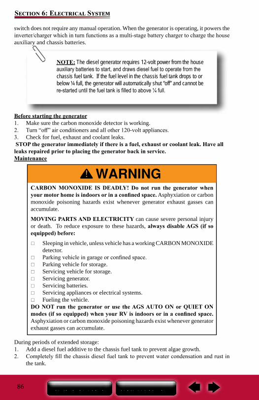
86
Section 6: Electrical System
CARBON MONOXIDE IS DEADLY! Do not run the generator when your motor home is indoors or in a confined space. Asphyxiation or carbon monoxide poisoning hazards exist whenever generator exhaust gasses can accumulate.
MOVING PARTS AND ELECTRICITY can cause severe personal injury or death. To reduce exposure to these hazards, always disable AGS (if so equipped) before:
Sleeping in vehicle, unless vehicle has a working CARBON MONOXIDE detector.
Parking vehicle in garage or confined space. Parking vehicle for storage. Servicing vehicle for storage. Servicing generator. Servicing batteries. Servicing appliances or electrical systems. Fueling the vehicle.
DO NOT run the generator or use the AGS AUTO ON or QUIET ON modes (if so equipped) when your RV is indoors or in a confined space. Asphyxiation or carbon monoxide poisoning hazards exist whenever generator exhaust gasses can accumulate.
switch does not require any manual operation. When the generator is operating, it powers the inverter/charger which in turn functions as a multi-stage battery charger to charge the house auxiliary and chassis batteries.
Before starting the generator1. Make sure the carbon monoxide detector is working.2. Turn “off” air conditioners and all other 120-volt appliances.3. Check for fuel, exhaust and coolant leaks. STOP the generator immediately if there is a fuel, exhaust or coolant leak. Have all leaks repaired prior to placing the generator back in service.Maintenance
During periods of extended storage:1. Add a diesel fuel additive to the chassis fuel tank to prevent algae growth.2. Completely fill the chassis diesel fuel tank to prevent water condensation and rust in
the tank.
NOTE: The diesel generator requires 12-volt power from the house auxiliary batteries to start, and draws diesel fuel to operate from the chassis fuel tank. If the fuel level in the chassis fuel tank drops to or below ¼ full, the generator will automatically shut “off” and cannot be re-started until the fuel tank is filled to above ¼ full.
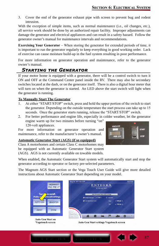
87
Section 6: Electrical System
Starting the GeneratorIf your motor home is equipped with a generator, there will be a control switch to turn it ON and OFF at the Command Center panel inside the RV. There may also be secondary switches located at the dash, or on the generator itself. There is also a digital hour meter that will turn on when the generator is started. An LED above the start switch will light when the generator is running.
To Manually Start The Generator1. At either “START/STOP” switch, press and hold the upper portion of the switch to start
the generator. Depending on the outside temperature the start process can take up to 15 seconds. Once the generator starts running, release the “START/STOP” switch.
2. For better performance and engine life, especially in colder weather, let the generator engine warm up for two minutes before turning “on” 120-volt appliances.
For more information on generator operation and maintenance, refer to the manufacturer’s owner’s manual.
Automatic Generator Start (AGS) (if so equipped)Class A motorhomes and certain Class C motorhomes may be equipped with an Automatic Generator Start system (AGS). AGS is not currently available on towable models.
When enabled, the Automatic Generator Start system will automatically start and stop the generator according to operator or factory pre-selected parameters.
The Magnum AGS Start section or the Vega Touch User Guide will give more detailed instructions about Automatic Generator Start depending on your model.
3. Cover the end of the generator exhaust pipe with screen to prevent bug and rodent intrusion.
With the exception of simple items, such as normal maintenance (i.e., oil changes, etc.), all service work should be done by an authorized repair facility. Improper adjustments can damage the generator and electrical appliances and can result in a safety hazard. Follow the generator owner’s manual for maintenance intervals and recommendations.
Exercising Your Generator – When storing the generator for extended periods of time, it is important to run the generator regularly to keep everything in good working order. Lack of exercise can cause moisture build-up in the fuel system resulting in poor performance.
For more information on generator operation and maintenance, refer to the generator owner’s manual.
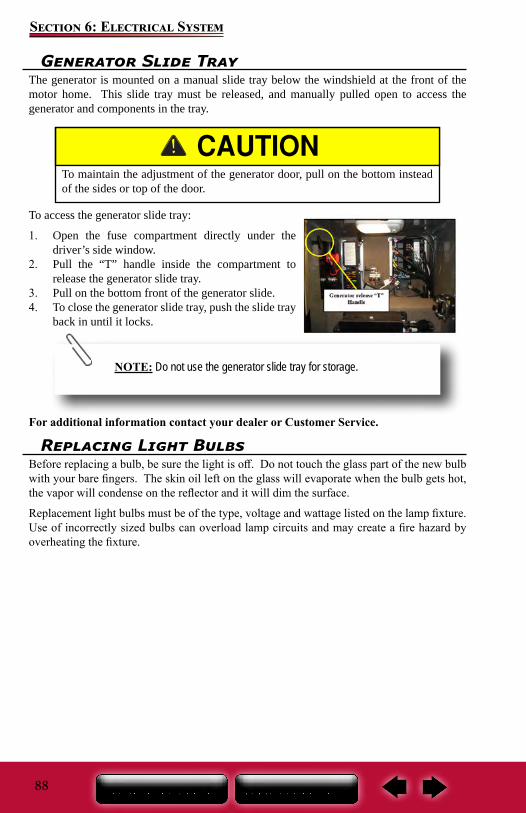
88
Section 6: Electrical System
Generator Slide TrayThe generator is mounted on a manual slide tray below the windshield at the front of the motor home. This slide tray must be released, and manually pulled open to access the generator and components in the tray.
To access the generator slide tray:
1. Open the fuse compartment directly under the driver’s side window.
2. Pull the “T” handle inside the compartment to release the generator slide tray.
3. Pull on the bottom front of the generator slide.4. To close the generator slide tray, push the slide tray
back in until it locks.
For additional information contact your dealer or Customer Service.
To maintain the adjustment of the generator door, pull on the bottom instead of the sides or top of the door.
NOTE: Do not use the generator slide tray for storage.
Replacing Light BulbsBefore replacing a bulb, be sure the light is off. Do not touch the glass part of the new bulb with your bare fingers. The skin oil left on the glass will evaporate when the bulb gets hot, the vapor will condense on the reflector and it will dim the surface.
Replacement light bulbs must be of the type, voltage and wattage listed on the lamp fixture. Use of incorrectly sized bulbs can overload lamp circuits and may create a fire hazard by overheating the fixture.
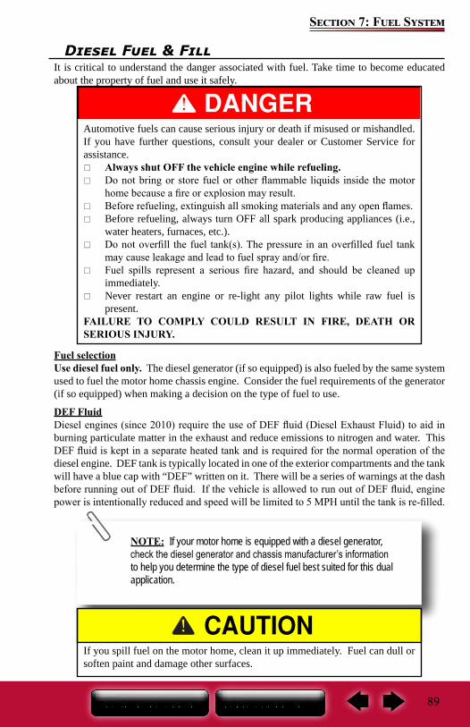
89
Section 7: Fuel System
Diesel Fuel & FillIt is critical to understand the danger associated with fuel. Take time to become educated about the property of fuel and use it safely.
Fuel selectionUse diesel fuel only. The diesel generator (if so equipped) is also fueled by the same system used to fuel the motor home chassis engine. Consider the fuel requirements of the generator (if so equipped) when making a decision on the type of fuel to use.
DEF FluidDiesel engines (since 2010) require the use of DEF fluid (Diesel Exhaust Fluid) to aid in burning particulate matter in the exhaust and reduce emissions to nitrogen and water. This DEF fluid is kept in a separate heated tank and is required for the normal operation of the diesel engine. DEF tank is typically located in one of the exterior compartments and the tank will have a blue cap with “DEF” written on it. There will be a series of warnings at the dash before running out of DEF fluid. If the vehicle is allowed to run out of DEF fluid, engine power is intentionally reduced and speed will be limited to 5 MPH until the tank is re-filled.
Automotive fuels can cause serious injury or death if misused or mishandled. If you have further questions, consult your dealer or Customer Service for assistance.
Always shut OFF the vehicle engine while refueling. Do not bring or store fuel or other flammable liquids inside the motor
home because a fire or explosion may result. Before refueling, extinguish all smoking materials and any open flames. Before refueling, always turn OFF all spark producing appliances (i.e.,
water heaters, furnaces, etc.). Do not overfill the fuel tank(s). The pressure in an overfilled fuel tank
may cause leakage and lead to fuel spray and/or fire. Fuel spills represent a serious fire hazard, and should be cleaned up
immediately. Never restart an engine or re-light any pilot lights while raw fuel is
present.FAILURE TO COMPLY COULD RESULT IN FIRE, DEATH OR SERIOUS INJURY.
NOTE: If your motor home is equipped with a diesel generator, check the diesel generator and chassis manufacturer’s information to help you determine the type of diesel fuel best suited for this dual application.
If you spill fuel on the motor home, clean it up immediately. Fuel can dull or soften paint and damage other surfaces.
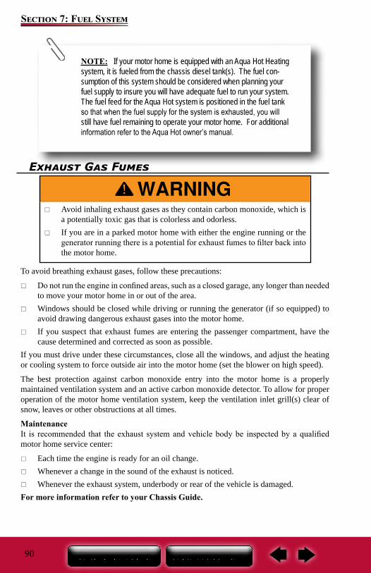
90
Section 7: Fuel System
NOTE: If your motor home is equipped with an Aqua Hot Heating system, it is fueled from the chassis diesel tank(s). The fuel con-sumption of this system should be considered when planning your fuel supply to insure you will have adequate fuel to run your system. The fuel feed for the Aqua Hot system is positioned in the fuel tank so that when the fuel supply for the system is exhausted, you will still have fuel remaining to operate your motor home. For additional information refer to the Aqua Hot owner’s manual.
Exhaust Gas Fumes
To avoid breathing exhaust gases, follow these precautions:
Do not run the engine in confined areas, such as a closed garage, any longer than needed to move your motor home in or out of the area.
Windows should be closed while driving or running the generator (if so equipped) to avoid drawing dangerous exhaust gases into the motor home.
If you suspect that exhaust fumes are entering the passenger compartment, have the cause determined and corrected as soon as possible.
If you must drive under these circumstances, close all the windows, and adjust the heating or cooling system to force outside air into the motor home (set the blower on high speed).
The best protection against carbon monoxide entry into the motor home is a properly maintained ventilation system and an active carbon monoxide detector. To allow for proper operation of the motor home ventilation system, keep the ventilation inlet grill(s) clear of snow, leaves or other obstructions at all times.
MaintenanceIt is recommended that the exhaust system and vehicle body be inspected by a qualified motor home service center:
Each time the engine is ready for an oil change. Whenever a change in the sound of the exhaust is noticed. Whenever the exhaust system, underbody or rear of the vehicle is damaged.
For more information refer to your Chassis Guide.
Avoid inhaling exhaust gases as they contain carbon monoxide, which is a potentially toxic gas that is colorless and odorless.
If you are in a parked motor home with either the engine running or the generator running there is a potential for exhaust fumes to filter back into the motor home.
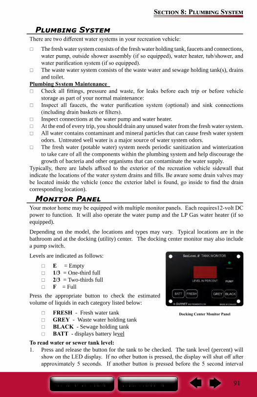
91
Section 8: Plumbing System
Plumbing System There are two different water systems in your recreation vehicle:
The fresh water system consists of the fresh water holding tank, faucets and connections, water pump, outside shower assembly (if so equipped), water heater, tub/shower, and water purification system (if so equipped).
The waste water system consists of the waste water and sewage holding tank(s), drains and toilet.
Plumbing System Maintenance Check all fittings, pressure and waste, for leaks before each trip or before vehicle
storage as part of your normal maintenance: Inspect all faucets, the water purification system (optional) and sink connections
(including drain baskets or filters). Inspect connections at the water pump and water heater. At the end of every trip, you should drain any unused water from the fresh water system. All water contains contaminant and mineral particles that can cause fresh water system
odors. Untreated well water is a major source of water system odors. The fresh water (potable water) system needs periodic sanitization and winterization
to take care of all the components within the plumbing system and help discourage the growth of bacteria and other organisms that can contaminate the water supply.
Typically, there are labels affixed to the exterior of the recreation vehicle sidewall that indicate the locations of the water system drains and fills. Be aware some drain valves may be located inside the vehicle (once the exterior label is found, go inside to find the drain corresponding location).
Monitor PanelYour motor home may be equipped with multiple monitor panels. Each requires12-volt DC power to function. It will also operate the water pump and the LP Gas water heater (if so equipped).
Depending on the model, the locations and types may vary. Typical locations are in the bathroom and at the docking (utility) center. The docking center monitor may also include a pump switch.
Levels are indicated as follows:
E = Empty 1/3 = One-third full 2/3 = Two-thirds full F = Full
Press the appropriate button to check the estimated volume of liquids in each category listed below:
FRESH - Fresh water tank GREY - Waste water holding tank BLACK - Sewage holding tank BATT - displays battery level
To read water or sewer tank level:1. Press and release the button for the tank to be checked. The tank level (percent) will
show on the LED display. If no other button is pressed, the display will shut off after approximately 5 seconds. If another button is pressed before the 5 second interval
Docking Center Monitor Panel
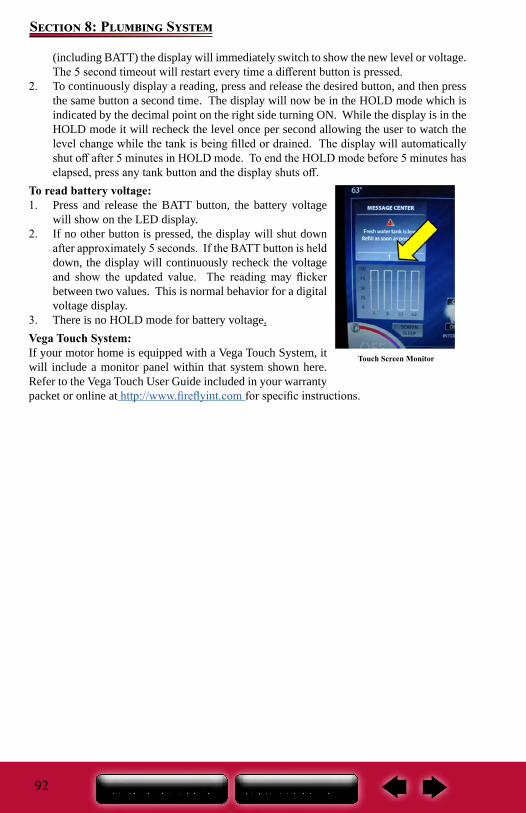
92
Section 8: Plumbing System
(including BATT) the display will immediately switch to show the new level or voltage. The 5 second timeout will restart every time a different button is pressed.
2. To continuously display a reading, press and release the desired button, and then press the same button a second time. The display will now be in the HOLD mode which is indicated by the decimal point on the right side turning ON. While the display is in the HOLD mode it will recheck the level once per second allowing the user to watch the level change while the tank is being filled or drained. The display will automatically shut off after 5 minutes in HOLD mode. To end the HOLD mode before 5 minutes has elapsed, press any tank button and the display shuts off.
To read battery voltage:1. Press and release the BATT button, the battery voltage
will show on the LED display.2. If no other button is pressed, the display will shut down
after approximately 5 seconds. If the BATT button is held down, the display will continuously recheck the voltage and show the updated value. The reading may flicker between two values. This is normal behavior for a digital voltage display.
3. There is no HOLD mode for battery voltage.Vega Touch System:If your motor home is equipped with a Vega Touch System, it will include a monitor panel within that system shown here. Refer to the Vega Touch User Guide included in your warranty packet or online at http://www.fireflyint.com for specific instructions.
Touch Screen Monitor
93
Section 8: Plumbing System
Fresh Water SystemAll water contains contaminant and mineral particles that can cause fresh water system odors. Untreated well water is a major source of water system odors. The fresh water (potable water) system needs periodic sanitization to take care of all the components in the plumbing system to discourage the growth of bacteria and other organisms that can contaminate the water supply.
Water Pressure Regulator (Customer Supplied)Excessive pressure from the water supply source may be encountered in some parks, especially in mountain regions when using the fresh water inlet or black tank flush. Water pressure regulators are available to protect your recreational vehicles plumbing system against such high pressure.
Fresh Water Holding TankThere may be several ways to fill the fresh water tank depending on the model. For details of each method, refer to the Fresh Water Connections or the Utility Center) sections. There are plastic overflow tubes in the fresh water holding tank which allow water to flow out of the water tank. Occasionally, you may see water coming from the overflow tubes when the fresh water holding tank is filled. This is normal and can be a result of the recreation vehicle being parked on an incline, or the motion caused by starting or stopping during travel.
City Water Fill
NOTE: If needed, sanitize the water system prior to travel
DO NOT drink water deemed microbiologically unsafe or of unknown quality.
Never travel with full fresh, black or grey water holding tanks.
A water pressure regulator is recommended to prevent damage to the plumbing system or components. To prevent damage when using the city water connection, a 45 lb. (315 KPa) rated water pressure regulator is recommended.
Do not cap, block or modify the fresh water tank overflow tubes in any way. Enough water pressure can build up during the filling process to damage the plumbing system if the overflow tubes are obstructed.
Be careful not to overfill the fresh water holding tank. It can pressurize the tank, causing leakage and water damage and void the warranty. DO NOT leave the tank unattended while filling.
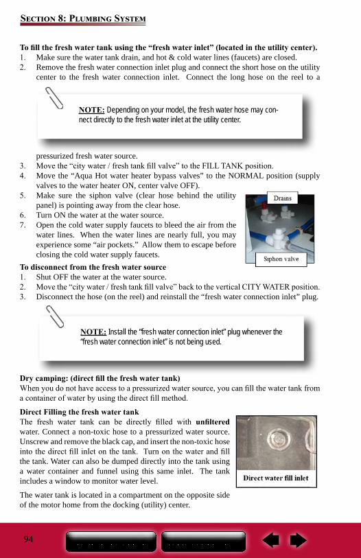
94
Section 8: Plumbing System
To fill the fresh water tank using the “fresh water inlet” (located in the utility center).1. Make sure the water tank drain, and hot & cold water lines (faucets) are closed.2. Remove the fresh water connection inlet plug and connect the short hose on the utility
center to the fresh water connection inlet. Connect the long hose on the reel to a
pressurized fresh water source.3. Move the “city water / fresh tank fill valve” to the FILL TANK position.4. Move the “Aqua Hot water heater bypass valves” to the NORMAL position (supply
valves to the water heater ON, center valve OFF).5. Make sure the siphon valve (clear hose behind the utility
panel) is pointing away from the clear hose.6. Turn ON the water at the water source.7. Open the cold water supply faucets to bleed the air from the
water lines. When the water lines are nearly full, you may experience some “air pockets.” Allow them to escape before closing the cold water supply faucets.
To disconnect from the fresh water source1. Shut OFF the water at the water source.2. Move the “city water / fresh tank fill valve” back to the vertical CITY WATER position.3. Disconnect the hose (on the reel) and reinstall the “fresh water connection inlet” plug.
Dry camping: (direct fill the fresh water tank)When you do not have access to a pressurized water source, you can fill the water tank from a container of water by using the direct fill method.
Direct Filling the fresh water tankThe fresh water tank can be directly filled with unfiltered water. Connect a non-toxic hose to a pressurized water source. Unscrew and remove the black cap, and insert the non-toxic hose into the direct fill inlet on the tank. Turn on the water and fill the tank. Water can also be dumped directly into the tank using a water container and funnel using this same inlet. The tank includes a window to monitor water level.
The water tank is located in a compartment on the opposite side of the motor home from the docking (utility) center.
NOTE: Depending on your model, the fresh water hose may con-nect directly to the fresh water inlet at the utility center.
NOTE: Install the “fresh water connection inlet” plug whenever the “fresh water connection inlet” is not being used.
95
Section 8: Plumbing System
12-volt Water Pump & Water Pump SwitchesYour motor home is equipped with (2) three-way water pump switches located on the interior and the exterior monitor panel. Either switch will control the water pump.
Once activated, the water (demand) pump will self-prime, and provide water. The water pump continues to run until maximum pressure is achieved and shut off. The water pump will automatically re-start when it senses a drop in the water pressure. Some cycling may occur, depending on the volume of water being released. The water pump is engineered with a check valve to prevent water from back flowing into the fresh water supply tank.
When you want to use water in your motor home and it is not hooked up to city water, you will need sufficient 12-volt DC power to run the water pump.
MaintenanceNormal pump maintenance consists of checking and cleaning of the strainer, normal sanitizing and winterizing and occasionally checking all plumbing hardware and fittings for tightness.
Lack of sanitizing can lead to premature pump failure and poor performance over time. Scale build-up on the diaphragm and valves, can cause low flow and leak back (occasional pump cycling with no faucets open or tank filling up when hooked up to city water).
For more information, refer to the water pump manufacturer’s user guide.
Water Purification System (If So Equipped)Primary water filter: The canister filter is the primary filter used for the complete water system. It is located at the docking (utility) center of the motor home. If the water supply has not been used for some time, allow the water to flow for several minutes to flush the system.
NOTE:The water pump switch should be in the OFF position when the motor home is left unattended for any amount of time.
DO NOT drink water deemed microbiologically unsafe or of unknown quality.
NOTE: This method of filling the water tank is NOT recommended if filtered water is required. The only method to fill the fresh water tank with filtered water is by using the fresh water connection inlet and the city water / tank fill valve on the docking (utility) center panel.
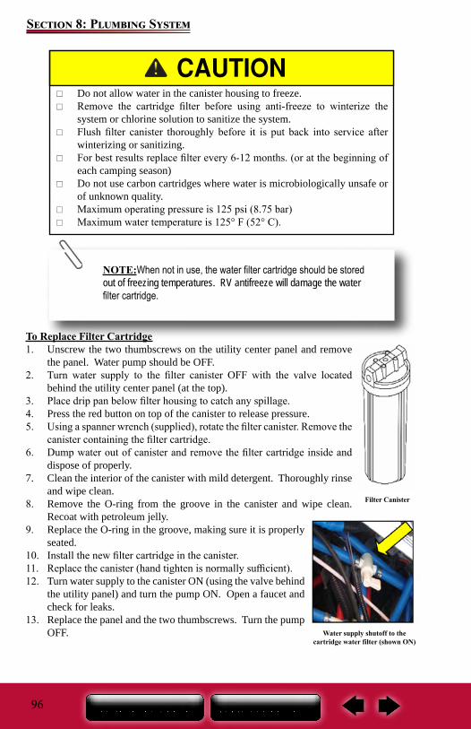
96
Section 8: Plumbing System
To Replace Filter Cartridge1. Unscrew the two thumbscrews on the utility center panel and remove
the panel. Water pump should be OFF.2. Turn water supply to the filter canister OFF with the valve located
behind the utility center panel (at the top).3. Place drip pan below filter housing to catch any spillage.4. Press the red button on top of the canister to release pressure.5. Using a spanner wrench (supplied), rotate the filter canister. Remove the
canister containing the filter cartridge.6. Dump water out of canister and remove the filter cartridge inside and
dispose of properly.7. Clean the interior of the canister with mild detergent. Thoroughly rinse
and wipe clean.8. Remove the O-ring from the groove in the canister and wipe clean.
Recoat with petroleum jelly.9. Replace the O-ring in the groove, making sure it is properly
seated.10. Install the new filter cartridge in the canister.11. Replace the canister (hand tighten is normally sufficient).12. Turn water supply to the canister ON (using the valve behind
the utility panel) and turn the pump ON. Open a faucet and check for leaks.
13. Replace the panel and the two thumbscrews. Turn the pump OFF.
Filter Canister
Do not allow water in the canister housing to freeze. Remove the cartridge filter before using anti-freeze to winterize the
system or chlorine solution to sanitize the system. Flush filter canister thoroughly before it is put back into service after
winterizing or sanitizing. For best results replace filter every 6-12 months. (or at the beginning of
each camping season) Do not use carbon cartridges where water is microbiologically unsafe or
of unknown quality. Maximum operating pressure is 125 psi (8.75 bar) Maximum water temperature is 125° F (52° C).
NOTE:When not in use, the water filter cartridge should be stored out of freezing temperatures. RV antifreeze will damage the water filter cartridge.
Water supply shutoff to the cartridge water filter (shown ON)
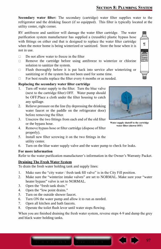
97
Section 8: Plumbing System
Secondary water filter: The secondary (cartridge) water filter supplies water to the refrigerator and the drinking faucet (if so equipped). This filter is typically located at the utility center, right corner.
RV antifreeze and sanitizer will damage the water filter cartridge. The water purification system manufacturer has supplied a (reusable) plastic bypass hose with fittings on either end that is designed to replace the water filter cartridge when the motor home is being winterized or sanitized. Store the hose when it is not in use.
Do not allow water to freeze in the filter Remove the cartridge before using antifreeze to winterize or chlorine
solution to sanitize the system. Flush thoroughly before it is put back into service after winterizing or
sanitizing or if the system has not been used for some time. For best results replace the filter every 6 months or as needed.
Replacing the secondary water filter cartridge 1. Turn off water supply to the filter. Turn the blue valve
(next to the cartridge filter) OFF. Water pump should be OFF.Place a cloth under the filter housing to catch any spillage.
2. Relieve pressure on the line (by depressing the drinking water faucet or the paddle on the refrigerator door) before removing the filter.
3. Unscrew the two fittings from each end of the old filter or the bypass hose.
4. Remove bypass hose or filter cartridge (dispose of filter properly).
5. Install new filter screwing it on the two fittings in the utility center.
6. Turn on the blue water supply valve and the water pump to check for leaks.For more informationRefer to the water purification manufacturer’s information in the Owner’s Warranty Packet.
Draining The Fresh Water SystemTo drain the fresh water holding tank and supply lines:
1. Make sure the “city water / fresh tank fill valve” is in the City Fill position.2. Make sure the “winterize intake valves” are set to NORMAL. Make sure your “water
heater bypass” valve is set to NORMAL.3. Open the “fresh tank drain.”4. Open the “low point drains.”5. Turn on the outside shower faucet.6. Turn ON the water pump and allow it to run as needed.7. Open all kitchen and bath faucets.8. Operate the toilet flush lever until water stops flowing.When you are finished draining the fresh water system, reverse steps 4-9 and dump the grey and black water holding tanks.
Water supply shutoff to the cartridge water filter (shown OFF)
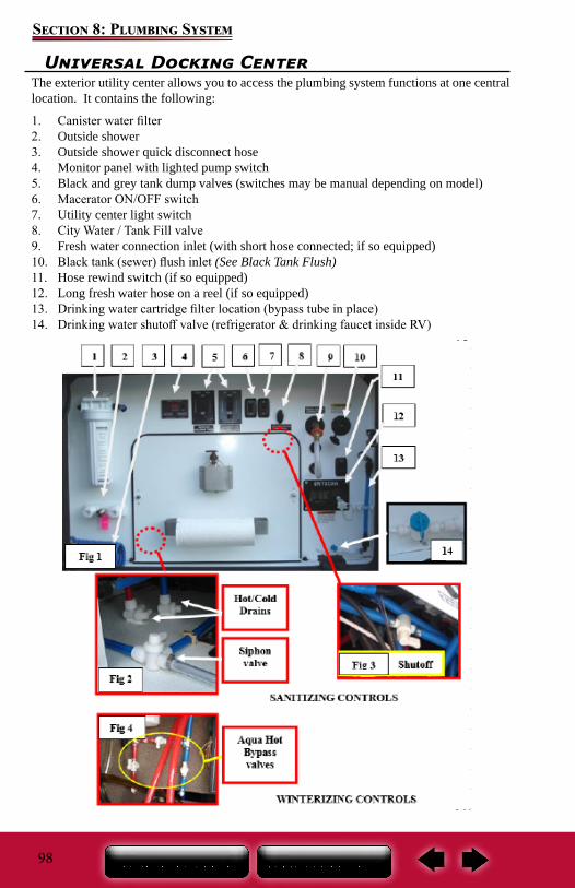
98
Section 8: Plumbing System
Universal Docking CenterThe exterior utility center allows you to access the plumbing system functions at one central location. It contains the following:
1. Canister water filter2. Outside shower3. Outside shower quick disconnect hose4. Monitor panel with lighted pump switch5. Black and grey tank dump valves (switches may be manual depending on model)6. Macerator ON/OFF switch7. Utility center light switch8. City Water / Tank Fill valve9. Fresh water connection inlet (with short hose connected; if so equipped)10. Black tank (sewer) flush inlet (See Black Tank Flush)11. Hose rewind switch (if so equipped)12. Long fresh water hose on a reel (if so equipped)13. Drinking water cartridge filter location (bypass tube in place)14. Drinking water shutoff valve (refrigerator & drinking faucet inside RV)
15. 16. 17. 18. 19. 20. 21. 22. 23. 24. 25. 26. 27. 28. 29. 30. 31. 32. 33. 34. 35. 36. 37. 38.
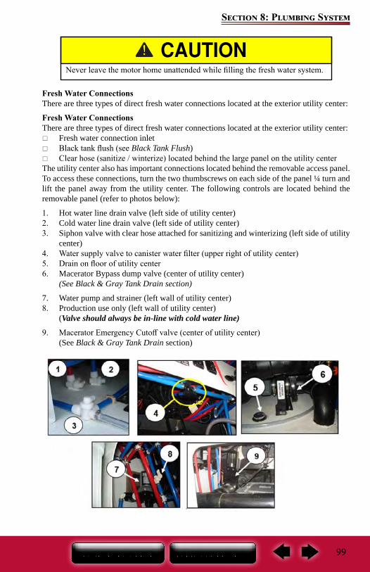
99
Section 8: Plumbing System
Fresh Water ConnectionsThere are three types of direct fresh water connections located at the exterior utility center:
Fresh Water ConnectionsThere are three types of direct fresh water connections located at the exterior utility center:
Fresh water connection inlet Black tank flush (see Black Tank Flush) Clear hose (sanitize / winterize) located behind the large panel on the utility center
The utility center also has important connections located behind the removable access panel. To access these connections, turn the two thumbscrews on each side of the panel ¼ turn and lift the panel away from the utility center. The following controls are located behind the removable panel (refer to photos below):
1. Hot water line drain valve (left side of utility center)2. Cold water line drain valve (left side of utility center)3. Siphon valve with clear hose attached for sanitizing and winterizing (left side of utility
center) 4. Water supply valve to canister water filter (upper right of utility center)5. Drain on floor of utility center6. Macerator Bypass dump valve (center of utility center)
(See Black & Gray Tank Drain section)
7. Water pump and strainer (left wall of utility center)8. Production use only (left wall of utility center)
(Valve should always be in-line with cold water line)
9. Macerator Emergency Cutoff valve (center of utility center)(See Black & Gray Tank Drain section)
Never leave the motor home unattended while filling the fresh water system.
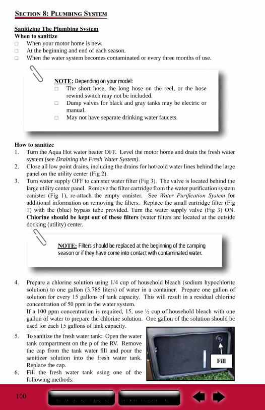
100
Section 8: Plumbing System
Sanitizing The Plumbing SystemWhen to sanitize
When your motor home is new. At the beginning and end of each season. When the water system becomes contaminated or every three months of use.
How to sanitize1. Turn the Aqua Hot water heater OFF. Level the motor home and drain the fresh water
system (see Draining the Fresh Water System).2. Close all low point drains, including the drains for hot/cold water lines behind the large
panel on the utility center (Fig 2).3. Turn water supply OFF to canister water filter (Fig 3). The valve is located behind the
large utility center panel. Remove the filter cartridge from the water purification system canister (Fig 1), re-attach the empty canister. See Water Purification System for additional information on removing the filters. Replace the small cartridge filter (Fig 1) with the (blue) bypass tube provided. Turn the water supply valve (Fig 3) ON. Chlorine should be kept out of these filters (water filters are located at the outside docking (utility) center.
4. Prepare a chlorine solution using 1/4 cup of household bleach (sodium hypochlorite solution) to one gallon (3.785 liters) of water in a container. Prepare one gallon of solution for every 15 gallons of tank capacity. This will result in a residual chlorine concentration of 50 ppm in the water system.If a 100 ppm concentration is required, 15, use ½ cup of household bleach with one gallon of water to prepare the chlorine solution. One gallon of the solution should be used for each 15 gallons of tank capacity.
5. To sanitize the fresh water tank: Open the water tank compartment on the p of the RV. Remove the cap from the tank water fill and pour the sanitizer solution into the fresh water tank. Replace the cap.
6. Fill the fresh water tank using one of the following methods:
NOTE: Depending on your model: The short hose, the long hose on the reel, or the hose
rewind switch may not be included. Dump valves for black and gray tanks may be electric or
manual. May not have separate drinking water faucets.
NOTE: Filters should be replaced at the beginning of the camping season or if they have come into contact with contaminated water.
101
Section 8: Plumbing System
Method 1: Remove the cap and fill the tank using a water hose. Monitor the water level using the water level guide.
Method 2: Attach the fresh water hose from the hose reel to a pressurized water source. The short hose at the utility center should connect to the City Water Inlet. Turn the Tank Fill / City Water valve on the utility center to TANK FILL (horizontal). Turn on the water until the tank is full.
7. When the water tank is full:Method 1: remove the hose and replace the cap on the water tank.
Method 2: shut off pressurized water source, disconnect water source from the hose reel, press and hold the HOSE REEL REWIND switch (Fig 1) to retract the hose back onto the reel (release the switch when the end of the hose gets to the panel).
On models where the water hose connects directly to the (utility center) water inlet; shut off water source, remove the hose from the city water inlet.
8. At utility center: place the city water valve to the vertical (city water) position.9. At the cartridge filter location on the utility panel (Fig. 1), turn OFF the drinking water
valve (Item 14), to prevent sanitizer from entering the refrigerator and the drinking faucet at the kitchen sink (valve is shown OFF). The valve color will be either black or blue.
10. Bypass the Aqua Hot water heater. Sanitizer must be kept out of the Aqua Hot water heater. Set the bypass valves to the bypass position (two supply valves OFF, middle valve ON). The 3 black valves are located with the Aqua Hot water heater (in this photo, supply valves are shown ON, bypass valve is shown OFF).
11. Turn the pump switch ON.12. Open the hot and cold water line faucets one at a time (kitchen, lavatory, shower and
outside shower) until water begins to flow continuously and a chlorine smell is noticeable. Close the hot and cold water faucets.
13. Turn the pump OFF.14. Let the solution remain in the system for at least four hours when disinfecting with 50
PPM residual chlorine. If a shorter time period is desired, then a 100 PPM chlorine concentration should be permitted to sit in the system for at least one hour. For complete fresh water tank sanitization, driving your motor home for a short distance will allow the sanitizing solution to splash around all sides of the tank.
NOTE: Depending on your model, the fresh water hose may con-nect directly to the fresh water inlet at the utility center.
NOTE:The shower hose must be connected to the outside shower.
102
Section 8: Plumbing System
15. After the required sanitization period, drain the chlorine solution from the fresh water system (see Draining the Fresh Water System).
16. Re-fill the fresh water tank. Verify that the city water valve is in the horizontal (fill tank) position (Fig. 1). Refer to Step 6 above to fill the fresh water tank.
17. Turn water source OFF. Set the city water valve back to the vertical (city water) position. Remove the hose from the water source. Turn the water pump ON. Open all faucets (including outside shower) to flush all the water lines with fresh water (pump is not used for this). Water heater bypass should still be ON (to prevent water from entering the water heater). Drinking water valve (Fig 1 Item 14) should still be OFF.
18. Drain the fresh water system again (see Draining the Fresh Water System). Re-fill the fresh water tank with potable water. Turn the water heater bypass valves to the normal position (hot & cold supply valves ON, middle valve OFF) to allow water into the Aqua Hot water heater. Detach the outside shower hose. Turn the drinking water valve ON (Fig 1 Item 14).
Water filter from the canister filter has been removed at the utility center. The small cartridge water filter must be replaced with the bypass tube. The blue drinking water valve (Fig. 1) at the cartridge water filter is OFF. Aqua Hot water heater is bypassed before flushing the system with the vinegar solution.
Re-flush the system with the vinegar solution through the faucets (steps 12 & 13) until chlorine smell is gone. Then flush the system again with fresh water. ONLY after the vinegar solution has been flushed out of the lines with fresh water, replace the water filters, turn the drinking water valve (Fig 1) back ON, and set the Aqua Hot bypass valves back to the normal position (hot & cold supply valves ON and middle valve OFF).
Winterizing The Plumbing SystemPreparing your motor home for colder weather or storage is very important for most states and Canada.
Failure to prepare your motor home may cause water supply lines and the water heater to freeze. Repairs due to freezing are not covered under the terms of the “Motorized Limited Warranty” applicable to the motor home.
No commodity or product should be added to the fresh water system to ensure freeze protection other than RV antifreeze.
Winterizing the Aqua-Hot system requires RV antifreeze in the potable water chamber to insure the heating coil is protected from freeze damage. The motor home antifreeze winterizing feature is located in the outside utility center. Refer to the Aqua-Hot owner’s manual for additional details.
NOTE:If a chlorine taste lingers in the water, flush the water system with a solution consisting of one-quart vinegar to five gallons of clean water. The following steps must be done before flushing the system with the vinegar solution:
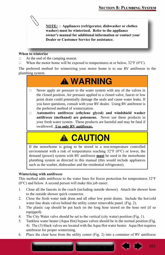
103
Section 8: Plumbing System
When to winterize At the end of the camping season. When the motor home will be exposed to temperatures at or below, 32°F (0°C).
The preferred method for winterizing your motor home is to use RV antifreeze in the plumbing system.
Winterizing with antifreezeThis method adds antifreeze to the water lines for freeze protection for temperatures 32°F (0°C) and below. A second person will make this job easier.
1. Close all the faucets in the coach (including outside shower). Attach the shower hose to the outside shower quick connector.
2. Close the fresh water tank drain and all other low point drains. Include the hot/cold water line drain valves behind the utility center removable panel. (Fig. 2).
3. The plastic cap should be put back on the long hose stored on the hose reel (if so equipped).
4. The City Water valve should be set to the vertical (city water) position (Fig. 1).5. Tankless water heater (Aqua Hot) bypass valves should be in the normal position (Fig.
4). The (3) black valves are located with the Aqua Hot water heater. Aqua Hot requires antifreeze for proper winterizing.
6. Place the clear hose from the utility center (Fig. 2) into a container of RV antifreeze
Never apply air pressure to the water system with any of the valves in the closed position. Air pressure applied to a closed valve, faucet or low point drain could potentially damage the seals and cause water leaks. If you have questions, consult with your RV dealer. Using RV antifreeze is the preferred method of winterization.
Automotive antifreeze (ethylene glycol) and windshield washer antifreeze (methanol) are poisonous. Never use these products in your fresh water system. These products are harmful and may be fatal if swallowed. Use only RV antifreeze.
If the motorhome is going to be stored in a non-temperature controlled environment with a risk of temperatures reaching 32°F (0°C) or lower, the demand (power) system with RV antifreeze must be used in the motorhome plumbing system as directed in this manual (this would include appliances such as the washer, dishwasher and the residential refrigerator).
NOTE: : Appliances (refrigerator, dishwasher or clothes washer) must be winterized. Refer to the appliance owner's manual for additional information or contact your Dealer or Customer Service for assistance.
104
Section 8: Plumbing System
(requires about 2 gallons). The clear hose is typically located behind the large panel on the utility center. The dashed circles in (Fig 1) indicate items that are behind the utility center panel.
7. Siphon valve should be turned so it is in-line with the clear plastic hose.8. Turn the water pump ON (Fig. 1) and antifreeze will be drawn out of the container and
into the water lines as each fixture is opened in the motorhome. To aid siphoning, place the antifreeze container on a flat surface approximately 2 feet off the ground.
Winterize the Macerator System (if so equipped)The macerator system can retain water in the flexible hose, the dump connector attached to the flex hose, and the macerator box and pipe. Pour antifreeze into the dump connector and into the 1-1/2-inch flexible hose. Raise the hose allowing the antifreeze to run back down into the macerator pipe and the macerator box. Return the flex hose and dump connector to the storage box.
Completing the Winterizing with antifreeze9. After all of the water lines/appliances have been winterized, turn the pump OFF and
disconnect the shower hose from the outside shower.10. Turn the siphon valve so it points away from the clear hose (Fig 2). Valve is located
behind the large panel on the utility center.11. Open the drain valve on the fresh water tank and leave it open.12. Add a cup of antifreeze in all the drain p-traps.13. Remove the clear hose from the container of RV antifreeze and clean.
14. Wipe the antifreeze out of the sinks, shower, and toilet using a soft, dry cloth.To De-Winterize the fresh water systemClose the fresh water drain valve. Fill the fresh water tank with fresh water and rinse the RV antifreeze from each faucet or appliance that was protected with the RV antifreeze.
Fill the fresh water tank using one of the following methods:
Method 1: Connect the short hose to the city water connection inlet on the utility center. Attach the long hose on the hose reel to a pressurized fresh water source.
NOTE: To reduce the chance of contamination, prevent the clear hose from coming into contact with the ground or the water fittings.
NOTE: Depending on your model:
The short hose, the long hose on the reel, or the hose rewind switch may not be included.
Dump valves for gray and black tanks may be electric or manual.
May not have separate drinking water faucets.
105
Section 8: Plumbing System
The city water valve (Fig 1) should be turned to the Tank Fill position (horizontal). Turn water source ON and fill the tank.
Method 2: Open the water tank compartment on the DOOR SIDE of the RV. Remove the fill cap from the water tank. Insert a hose (connected to a fresh water source) into the water tank. If there is a drain valve for the tank, it should be turned OFF. Turn water source ON and fill the tank.
Turn off and disconnect the water source. Turn the pump ON. Purge all antifreeze out of the water lines by opening all faucets (including outside shower).
Once all the antifreeze is out of the water lines, turn pump OFF, replace the canister water filter, remove the cartridge filter bypass tube and replace the cartridge drinking water filter (Fig. 1). Sanitize the system as necessary.
De-Winterize the Macerator Toilet: Press either button to flush and return to normal condition.
De-Winterize the Macerator System: Emptying the black tanks for the first time in the spring, will discharge antifreeze in the macerator pipe and flex hose.
NOTE: Depending on your model, the fresh water hose may con-nect directly to the fresh water inlet at the utility center.
Aqua-Hot Heating SystemThe following is an overview of the system operation. Read the manufacturer’s owner’s manual before operating this appliance. An Aqua-Hot manual is provided and if your copy is missing, please contact your Entegra Coach Dealer, Entegra Coach Factory service, or Aqua-Hot customer service immediately.
The Aqua-Hot system serves as the water heater and a hot water heating system for your motor home.
Water Heater: For hot water use, select and turn on one of the heating modes on the Aqua-Hot switch located in the bathroom of the motor home. Be sure there is power to the Aqua-Hot appliance and water in the system. Allow sufficient time for the appliance to heat the water for your needs. To run water at the faucets, make sure the 12 volt pump is on or the city water connection is hooked up, the tank fill/city fill valve should be set to city fill, and the supply faucet is in the on position.
Heating: Set the desired temperature on the Comfort Control Center thermostat and select the mode you wish to use on the Aqua-Hot control switch.
To determine which mode you wish to use, consider that the Diesel-Burner will provide more BTUs for heating in colder weather while the electric can warm the unit in cool temperatures that require less demand for heat. To utilize this heat mode, turn on the thermostat and set the furnace mode to the temperature you desire. In cold weather, you may need to use the Diesel-Burner mode to bring the heating temperature up to heating temperature.
Note that, in extreme cold temperatures, the Diesel-Burner may be needed to supplement heating of the antifreeze heating solution.
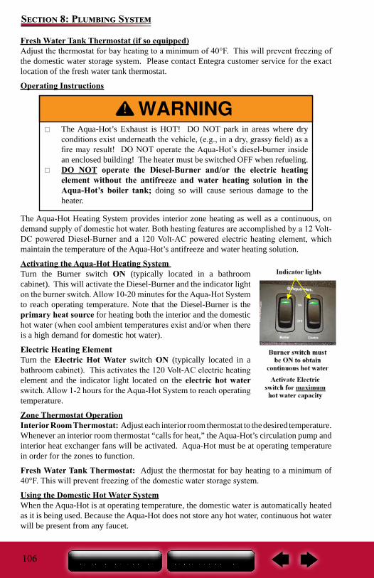
106
Section 8: Plumbing System
Fresh Water Tank Thermostat (if so equipped)Adjust the thermostat for bay heating to a minimum of 40°F. This will prevent freezing of the domestic water storage system. Please contact Entegra customer service for the exact location of the fresh water tank thermostat.
Operating Instructions
The Aqua-Hot Heating System provides interior zone heating as well as a continuous, on demand supply of domestic hot water. Both heating features are accomplished by a 12 Volt-DC powered Diesel-Burner and a 120 Volt-AC powered electric heating element, which maintain the temperature of the Aqua-Hot’s antifreeze and water heating solution.
Activating the Aqua-Hot Heating System Turn the Burner switch ON (typically located in a bathroom cabinet). This will activate the Diesel-Burner and the indicator light on the burner switch. Allow 10-20 minutes for the Aqua-Hot System to reach operating temperature. Note that the Diesel-Burner is the primary heat source for heating both the interior and the domestic hot water (when cool ambient temperatures exist and/or when there is a high demand for domestic hot water).
Electric Heating ElementTurn the Electric Hot Water switch ON (typically located in a bathroom cabinet). This activates the 120 Volt-AC electric heating element and the indicator light located on the electric hot water switch. Allow 1-2 hours for the Aqua-Hot System to reach operating temperature.
Zone Thermostat OperationInterior Room Thermostat: Adjust each interior room thermostat to the desired temperature. Whenever an interior room thermostat “calls for heat,” the Aqua-Hot’s circulation pump and interior heat exchanger fans will be activated. Aqua-Hot must be at operating temperature in order for the zones to function.
Fresh Water Tank Thermostat: Adjust the thermostat for bay heating to a minimum of 40°F. This will prevent freezing of the domestic water storage system.
Using the Domestic Hot Water SystemWhen the Aqua-Hot is at operating temperature, the domestic water is automatically heated as it is being used. Because the Aqua-Hot does not store any hot water, continuous hot water will be present from any faucet.
The Aqua-Hot’s Exhaust is HOT! DO NOT park in areas where dry conditions exist underneath the vehicle, (e.g., in a dry, grassy field) as a fire may result! DO NOT operate the Aqua-Hot’s diesel-burner inside an enclosed building! The heater must be switched OFF when refueling.
DO NOT operate the Diesel-Burner and/or the electric heating element without the antifreeze and water heating solution in the Aqua-Hot’s boiler tank; doing so will cause serious damage to the heater.
107
Section 8: Plumbing System
The Diesel-Burner switch must be ON in order to obtain a continuous supply of hot water; activate the electric element switch for maximum hot water capacity.
To heat the motor home/domestic hot water, choose the desired heat source(s) and leave the switch(s) (diesel and/or electric hot water) ON.
Electric Hot Water: When connected to shore power or when using the generator, the Aqua Hot electric heating element has the ability to function in order to provide heat for the boiler tank. The electric heating element is a secondary heat source for heating both the interior and the domestic hot water during low heating demand situations (moderate ambient temperatures exist and/or when there is a low demand for domestic hot water).
Maintenance (Aqua-Hot)Refer to the Aqua-Hot owner’s manual for detailed procedures, system requirements and parts information prior to performing any maintenance to the Aqua-Hot system.
Monthly MaintenanceCheck the Aqua-Hot’s antifreeze and water heating solution to ensure that it is at the proper level. This can be accomplished by visually checking the coolant level in the Aqua-Hot’s expansion tank.
The coolant level should be checked only when the Aqua-Hot is at maximum operating temperature (i.e., immediately after the Diesel-Burner cycles OFF). When the Aqua-Hot is at maximum operating temperature, the antifreeze and water heating solution should be at the level marked “HOT” on the expansion tank.
NOTE: The Aqua-Hot’s “Domestic Water Priority System” disables the interior zone heating fans and the zone circulation pumps whenever domestic hot water is being used on a continuous basis. Once the demand for continuous hot water ceases, the Aqua-Hot will enable the fans and the pumps to operate and provide heat to the heating system.
NOTE: Both the Diesel-Burner and the electric heating element are thermostatically controlled. Either, or both heating sources will automatically maintain the temperature of the antifreeze and water heating solution between approximately 160°F and 190°F (±5).
When the Aqua-Hot is at maximum operating temperature, the coolant will be very HOT! If Aqua-Hot’s heating system is accessed, scalding by hot vapor or coolant could result! Before cleaning or servicing, disconnect all power supplies!
108
Section 8: Plumbing SystemReplenishing the Antifreeze and Water Heating Solution:Refer to the Aqua Hot owner’s manual for details on how to replenish the water heating solution, including determining the correct ratio of antifreeze to water, the proper type of antifreeze, and the water quality recommendations for the antifreeze and water heating solution.
Annual Maintenance: Have the Diesel-Burner tuned-up annually. A tune-up should consist of a new fuel nozzle and fuel filter. Always use the recommended fuel nozzle and fuel filter when replacing these parts.
WinterizationThe Aqua-Hot’s Domestic Water Heating System must be completely drained of domestic water any time the heater is stored where freezing temperatures may be experienced.
Refer to the Aqua-Hot Owner’s Manual for detailed instructions for winterization and de-winterization of the Aqua-Hot appliance. Refer to Winterizing the Plumbing System in this manual for additional winterization information.
Troubleshooting (Aqua-Hot)Should the Aqua-Hot Hydronic Heating System fail to operate, complete the following checks:
1. Verify that the Aqua-Hot’s access cover is securely installed. The Aqua-Hot system will not operate if the access cover is not fully installed.
2. Ensure that the vehicle’s fuel tank contains a sufficient level of fuel. The Aqua-Hot system will not operate if the diesel fuel level is at or below 1/4 tank.
3. Ensure that the boiler tank has an adequate supply of antifreeze and water heating solution by checking the level at the expansion tank. If the level is low, reference the “Maintenance” section of the Aqua-Hot Owner’s Manual for refilling instructions.
4. Check the Aqua-Hot’s electronic controller for any RED lights indicating a fault condition. This control panel is located outside the coach with the Aqua Hot system. If the Aqua-Hot Heating System’s failure to operate is not resolved with the above checks, please contact Aqua-Hot Heating Systems Technical Support Department.
If the Aqua-Hot’s Diesel Burner indicator light does not illuminate, and the Diesel-Burner is not functioning, locate the electronic controller outside the coach and check the following:
NOTE: The Aqua-Hot can continue to be used for interior zone heating once the domestic water heating system has been drained and winterized.
Not winterizing the Aqua-Hot when freezing temperatures are present will result in serious damage to the Aqua-Hot’s domestic water heating system. Be sure to use an FDA approved, “GRAS” rated antifreeze for winterization. YOU CANNOT BLOW DOMESTIC WATER COIL OUT WITH AIR TO WINTERIZE AQUA-HOT
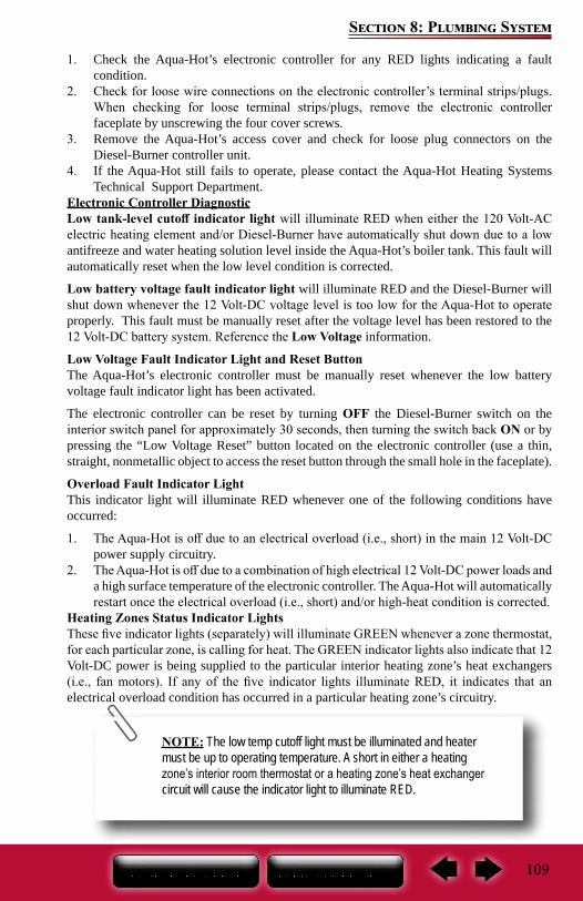
109
Section 8: Plumbing System
1. Check the Aqua-Hot’s electronic controller for any RED lights indicating a fault condition.
2. Check for loose wire connections on the electronic controller’s terminal strips/plugs. When checking for loose terminal strips/plugs, remove the electronic controller faceplate by unscrewing the four cover screws.
3. Remove the Aqua-Hot’s access cover and check for loose plug connectors on the Diesel-Burner controller unit.
4. If the Aqua-Hot still fails to operate, please contact the Aqua-Hot Heating Systems Technical Support Department.
Electronic Controller DiagnosticLow tank-level cutoff indicator light will illuminate RED when either the 120 Volt-AC electric heating element and/or Diesel-Burner have automatically shut down due to a low antifreeze and water heating solution level inside the Aqua-Hot’s boiler tank. This fault will automatically reset when the low level condition is corrected.
Low battery voltage fault indicator light will illuminate RED and the Diesel-Burner will shut down whenever the 12 Volt-DC voltage level is too low for the Aqua-Hot to operate properly. This fault must be manually reset after the voltage level has been restored to the 12 Volt-DC battery system. Reference the Low Voltage information.
Low Voltage Fault Indicator Light and Reset ButtonThe Aqua-Hot’s electronic controller must be manually reset whenever the low battery voltage fault indicator light has been activated.
The electronic controller can be reset by turning OFF the Diesel-Burner switch on the interior switch panel for approximately 30 seconds, then turning the switch back ON or by pressing the “Low Voltage Reset” button located on the electronic controller (use a thin, straight, nonmetallic object to access the reset button through the small hole in the faceplate).
Overload Fault Indicator LightThis indicator light will illuminate RED whenever one of the following conditions have occurred:
1. The Aqua-Hot is off due to an electrical overload (i.e., short) in the main 12 Volt-DC power supply circuitry.
2. The Aqua-Hot is off due to a combination of high electrical 12 Volt-DC power loads and a high surface temperature of the electronic controller. The Aqua-Hot will automatically restart once the electrical overload (i.e., short) and/or high-heat condition is corrected.
Heating Zones Status Indicator LightsThese five indicator lights (separately) will illuminate GREEN whenever a zone thermostat, for each particular zone, is calling for heat. The GREEN indicator lights also indicate that 12 Volt-DC power is being supplied to the particular interior heating zone’s heat exchangers (i.e., fan motors). If any of the five indicator lights illuminate RED, it indicates that an electrical overload condition has occurred in a particular heating zone’s circuitry.
NOTE: The low temp cutoff light must be illuminated and heater must be up to operating temperature. A short in either a heating zone’s interior room thermostat or a heating zone’s heat exchanger circuit will cause the indicator light to illuminate RED.
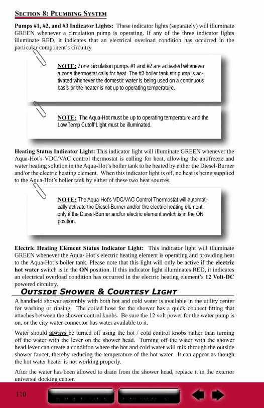
110
Section 8: Plumbing SystemPumps #1, #2, and #3 Indicator Lights: These indicator lights (separately) will illuminate GREEN whenever a circulation pump is operating. If any of the three indicator lights illuminate RED, it indicates that an electrical overload condition has occurred in the particular component’s circuitry.
Heating Status Indicator Light: This indicator light will illuminate GREEN whenever the Aqua-Hot’s VDC/VAC control thermostat is calling for heat, allowing the antifreeze and water heating solution in the Aqua-Hot’s boiler tank to be heated by either the Diesel-Burner and/or the electric heating element. When this indicator light is off, no heat is being supplied to the Aqua-Hot’s boiler tank by either of these two heat sources.
Electric Heating Element Status Indicator Light: This indicator light will illuminate GREEN whenever the Aqua- Hot’s electric heating element is operating and providing heat to the Aqua-Hot’s boiler tank. Please note that this light will only be active if the electric hot water switch is in the ON position. If this indicator light illuminates RED, it indicates an electrical overload condition has occurred in the electric heating element’s 12 Volt-DC powered circuitry.
NOTE: Zone circulation pumps #1 and #2 are activated whenever a zone thermostat calls for heat. The #3 boiler tank stir pump is ac-tivated whenever the domestic water is being used on a continuous basis or the heater is not up to operating temperature.
NOTE: The Aqua-Hot must be up to operating temperature and the Low Temp Cutoff Light must be illuminated.
NOTE: The Aqua-Hot’s VDC/VAC Control Thermostat will automati-cally activate the Diesel-Burner and/or the electric heating element only if the Diesel-Burner and/or electric element switch is in the ON position.
Outside Shower & Courtesy LightA handheld shower assembly with both hot and cold water is available in the utility center for washing or rinsing. The coiled hose for the shower has a quick connect fitting that attaches between the shower control knobs. Be sure the 12 volt power for the water pump is on, or the city water connector has water available to it.
Water should always be turned off using the hot / cold control knobs rather than turning off the water with the lever on the shower head. Turning off the water with the shower head lever can create a condition where the hot and cold water will mix through the outside shower faucet, thereby reducing the temperature of the hot water. It can appear as though the hot water heater is not working properly.
After the water has been allowed to drain from the shower head, replace it in the exterior universal docking center.
111
Section 8: Plumbing System
The courtesy light is operated with a rocker switch located on the utility center panel.
NOTE: Any remaining water in the shower hose will drip or run out; this is not a leak but performs as intended.
FaucetsThe bathroom, kitchen and outside shower faucets operate much the same way as the faucets in your home. Make sure there is sufficient water available and the 12-volt water pump is turned ON before operating.
NOTE: There may be air in the water plumbing lines which needs to be bled out before a steady stream of water comes from the faucet.
Bathroom ShowerKeep the water heater and holding tank capacities in mind when using the fresh water system. Be sure the water heater is ON and had sufficient time to heat the water.
If dry camping, be sure your 12-volt water pump is ON.Unlike your home, the motor home does not contain a water pressure balance valve. If someone is using the shower, it is recommended that the fresh water system NOT BE USED until they are finished.
The shower head may drip slightly in the OFF position after use; this is a normal function and does not indicate a leak or defect. The used water will drain through the plumbing pipes into the grey water holding tank.
MaintenanceUse mild dish soap and water to clean the fixtures. Never use harsh chemicals or sprays. A mild solution of vinegar and water works well to remove hard water spots and stains from the sink or shower fixtures.
Water temperatures over 125°F (49°C) can cause severe burns instantly therefore, be careful when using hot water. Always test the water temperature before showering or washing.
Black/Grey Water System and TanksWater from the sinks and shower flows into the gray water (or waste water) holding tank. Water from the toilet will flow into the sewage (or black water) holding tank (see Black/Grey Water Holding Tanks).
Drain Pipes with P-Trap (If So Equipped):The drain pipes may be equipped with a “P-trap” installed to help prevent odors from escaping into the RV. During travel, water from the P-traps may spill and permit odors into
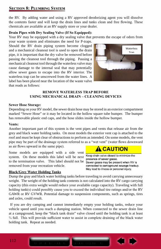
112
Section 8: Plumbing System
REMOVE WATERLESS TRAP BEFOREUSING MECHANICAL DRAIN – CLEANING DEVICES
the RV. By adding water and using a RV approved deodorizing agent you will dissolve the contents faster and will keep the drain lines and tanks clean and free flowing. These chemicals are available at an RV supply store or your dealer.
Drain Pipes with Dry Sealing Valve (If So Equipped):Your RV may be equipped with a dry sealing valve that prevents the escape of odors from your waste system and eliminates the need for P-traps. Should the RV drain piping system become clogged and a mechanical cleanout tool is used to open the drain pipe, it is important that the dry valve be removed before passing the cleanout tool through the piping. Passing a mechanical cleanout tool through the waterless valve may cause damage to the internal seal that may potentially allow sewer gases to escape into the RV interior. The waterless trap can be unscrewed from the water lines. A label has been placed near the location of the waste valve that reads as follows:
Sewer Hose Storage:Depending on your RV model, the sewer drain hose may be stored in an exterior compartment marked “Sewer Hose” or it may be located in the hollow square tube bumper. The bumper has removable plastic end caps, and the hose slides inside the hollow bumper.
Vents:Another important part of this system is the vent pipes and vents that release air from the grey and black water holding tanks. On most models the exterior vent cap is attached to the roof and must be kept clear of obstructions to perform as intended. On some models, the vent pipe may be part of the drainage system referred to as a “wet vent” (water flows downward as air flows upward in the same pipe).
Some models are equipped with a side vent system. On these models this label will be next to the termination valve. This label should not be removed from your recreation vehicle.
Black/Grey Water Holding TanksDump the gray and black water holding tanks before traveling to avoid carrying unnecessary weight. The weight of the holding tank contents is not calculated into the RV cargo carrying capacity (this extra weight would reduce your available cargo capacity). Traveling with full holding tank(s) could possibly cause you to exceed the individual tire ratings and/or the RV GAWR or RV GVWR. Potential damage to suspension components, such as springs, tires and axles, could result.
If you are dry camping and cannot immediately empty your holding tanks, reduce your vehicle speed until you reach a dumping station. When connected to the sewer drain line at a campground, keep the “black tank drain” valve closed until the holding tank is at least ¾ full. This will provide sufficient water to assist in complete draining of the black water holding tank. Repeat as needed.
Waterless Trap
113
Section 8: Plumbing System
Before using the recreation vehicle, or after dumping the grey and black water holding tanks, always add the proper amount of deodorant to the black water tank to prevent odors and help break down holding tank contents (unless winterizing). Follow the deodorant bottle or package instructions. Driving to a disposal site will normally loosen any accumulated waste debris or solids from the sides of the holding tanks.
Never travel with full black or grey water holding tanks. This not only wastes your fuel but depending on the location of the tank(s), it can affect your tow vehicle handling characteristics.
Never leave the black tank drain in the open position continuously when connected to the campground sewer system. Leaving the drain open will allow the liquid to drain out increasing the potential for a blockage in the tank. Keeping the drain in the closed position will prevent debris from accumulating in the tank.
Do not add automotive antifreeze or caustic chemicals, such as laundry detergents, into the holding tanks. Although these products may have a deodorizing effect, they may damage the plastic and rubber parts of the plumbing system or the components
Black /Gray Tank Drains & Macerator SystemThe gray tank drain and black tank drain (also referred to as dump valves) are typically located in the exterior utility center. Depending on your model the dump valves will be operated by either electric rocker switches or by a manual handle.
To make drainage easier, level the motor home. Always drain the black water holding tank first so the following wastewater can help rinse any solids or debris from the dump outlet and sewer hose.
Macerator Pump SystemYour motor home is equipped with a macerator pump system used to discharge waste from the gray and black waste tank. The system has a 1-1/2 inch diameter flexible hose that runs from the pump (behind the removable utility center panel) and attaches to a separate compartment on the exterior of the motor home (beside the utility center). Not all models are equipped with an external storage compartment. The system when powered on can discharge waste (uphill if necessary) up to a distance of 150 feet.
Before operating the macerator pump, make sure the external dump hose is properly attached at the motor home and at the dump station. The hose is under pressure and therefore waste is discharged under pressure. Failure to follow instructions can lead to possible injury or property damage. The use of this system for anything other than intended will void the warranty.
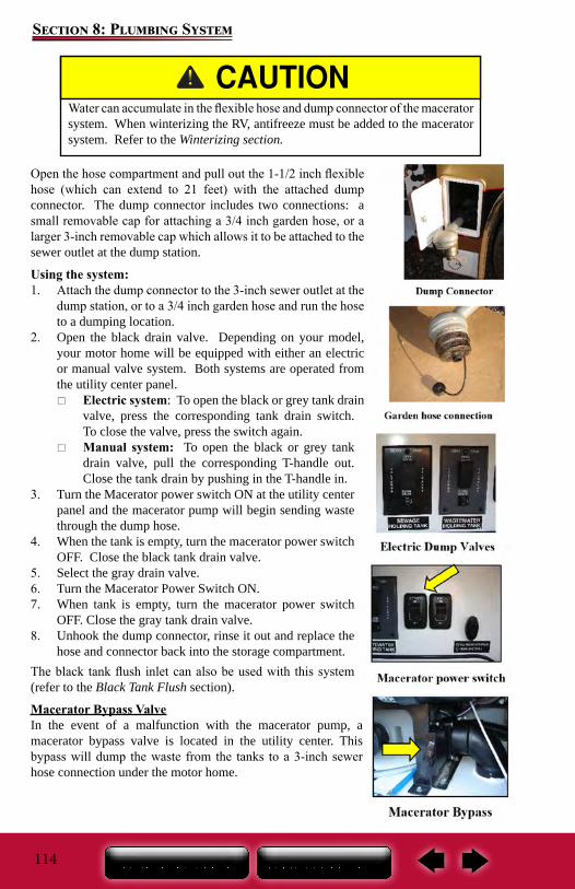
114
Section 8: Plumbing System
Water can accumulate in the flexible hose and dump connector of the macerator system. When winterizing the RV, antifreeze must be added to the macerator system. Refer to the Winterizing section.
Open the hose compartment and pull out the 1-1/2 inch flexible hose (which can extend to 21 feet) with the attached dump connector. The dump connector includes two connections: a small removable cap for attaching a 3/4 inch garden hose, or a larger 3-inch removable cap which allows it to be attached to the sewer outlet at the dump station.
Using the system:1. Attach the dump connector to the 3-inch sewer outlet at the
dump station, or to a 3/4 inch garden hose and run the hose to a dumping location.
2. Open the black drain valve. Depending on your model, your motor home will be equipped with either an electric or manual valve system. Both systems are operated from the utility center panel.
Electric system: To open the black or grey tank drain valve, press the corresponding tank drain switch. To close the valve, press the switch again.
Manual system: To open the black or grey tank drain valve, pull the corresponding T-handle out. Close the tank drain by pushing in the T-handle in.
3. Turn the Macerator power switch ON at the utility center panel and the macerator pump will begin sending waste through the dump hose.
4. When the tank is empty, turn the macerator power switch OFF. Close the black tank drain valve.
5. Select the gray drain valve.6. Turn the Macerator Power Switch ON.7. When tank is empty, turn the macerator power switch
OFF. Close the gray tank drain valve.8. Unhook the dump connector, rinse it out and replace the
hose and connector back into the storage compartment.The black tank flush inlet can also be used with this system (refer to the Black Tank Flush section).
Macerator Bypass ValveIn the event of a malfunction with the macerator pump, a macerator bypass valve is located in the utility center. This bypass will dump the waste from the tanks to a 3-inch sewer hose connection under the motor home.
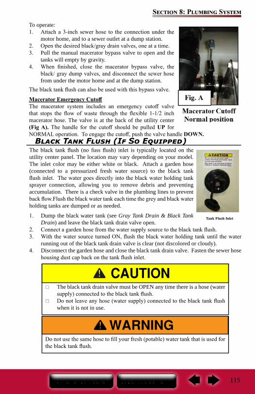
115
Section 8: Plumbing System
To operate:1. Attach a 3-inch sewer hose to the connection under the
motor home, and to a sewer outlet at a dump station.2. Open the desired black/gray drain valves, one at a time.3. Pull the manual macerator bypass valve to open and the
tanks will empty by gravity.4. When finished, close the macerator bypass valve, the
black/ gray dump valves, and disconnect the sewer hose from under the motor home and at the dump station.
The black tank flush can also be used with this bypass valve.
Macerator Emergency CutoffThe macerator system includes an emergency cutoff valve that stops the flow of waste through the flexible 1-1/2 inch macerator hose. The valve is at the back of the utility center (Fig A). The handle for the cutoff should be pulled UP for NORMAL operation. To engage the cutoff, push the valve handle DOWN.
Black Tank Flush (If So Equipped)The black tank flush (no fuss flush) inlet is typically located on the utility center panel. The location may vary depending on your model. The inlet color may be either white or black. Attach a garden hose (connected to a pressurized fresh water source) to the black tank flush inlet. The water goes directly into the black water holding tank sprayer connection, allowing you to remove debris and preventing accumulation. There is a check valve in the plumbing lines to prevent back flow.Flush the black water tank each time the grey and black water holding tanks are dumped or as needed.
1. Dump the black water tank (see Gray Tank Drain & Black Tank Drain) and leave the black tank drain valve open.
2. Connect a garden hose from the water supply source to the black tank flush.3. With the water source turned ON, flush the black water holding tank until the water
running out of the black tank drain valve is clear (not discolored or cloudy).4. Disconnect the garden hose and close the black tank drain valve. Fasten the sewer hose
housing dust cap back on the tank flush inlet.
Tank Flush Inlet
Do not use the same hose to fill your fresh (potable) water tank that is used for the black tank flush.
The black tank drain valve must be OPEN any time there is a hose (water supply) connected to the black tank flush.
Do not leave any hose (water supply) connected to the black tank flush when it is not in use.
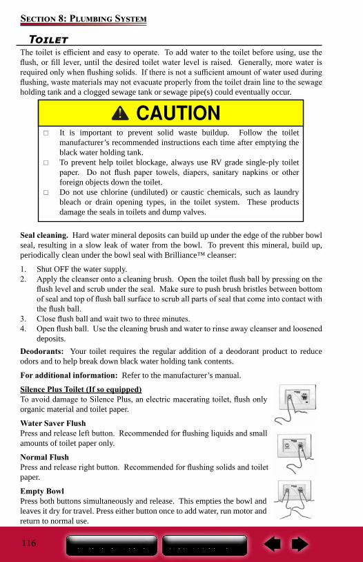
116
Section 8: Plumbing System
ToiletThe toilet is efficient and easy to operate. To add water to the toilet before using, use the flush, or fill lever, until the desired toilet water level is raised. Generally, more water is required only when flushing solids. If there is not a sufficient amount of water used during flushing, waste materials may not evacuate properly from the toilet drain line to the sewage holding tank and a clogged sewage tank or sewage pipe(s) could eventually occur.
Seal cleaning. Hard water mineral deposits can build up under the edge of the rubber bowl seal, resulting in a slow leak of water from the bowl. To prevent this mineral, build up, periodically clean under the bowl seal with Brilliance™ cleanser:
1. Shut OFF the water supply.2. Apply the cleanser onto a cleaning brush. Open the toilet flush ball by pressing on the
flush level and scrub under the seal. Make sure to push brush bristles between bottom of seal and top of flush ball surface to scrub all parts of seal that come into contact with the flush ball.
3. Close flush ball and wait two to three minutes.4. Open flush ball. Use the cleaning brush and water to rinse away cleanser and loosened
deposits.Deodorants: Your toilet requires the regular addition of a deodorant product to reduce odors and to help break down black water holding tank contents.
For additional information: Refer to the manufacturer’s manual.
Silence Plus Toilet (If so equipped)To avoid damage to Silence Plus, an electric macerating toilet, flush only organic material and toilet paper.
Water Saver FlushPress and release left button. Recommended for flushing liquids and small amounts of toilet paper only.
Normal FlushPress and release right button. Recommended for flushing solids and toilet paper.
Empty BowlPress both buttons simultaneously and release. This empties the bowl and leaves it dry for travel. Press either button once to add water, run motor and return to normal use.
It is important to prevent solid waste buildup. Follow the toilet manufacturer’s recommended instructions each time after emptying the black water holding tank.
To prevent help toilet blockage, always use RV grade single-ply toilet paper. Do not flush paper towels, diapers, sanitary napkins or other foreign objects down the toilet.
Do not use chlorine (undiluted) or caustic chemicals, such as laundry bleach or drain opening types, in the toilet system. These products damage the seals in toilets and dump valves.
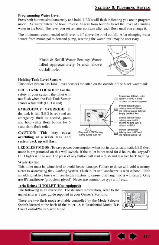
117
Section 8: Plumbing System
Programming Water LevelPress both buttons simultaneously and hold. LED’s will flash indicating you are in program mode. As water enters the bowl, release fingers from buttons to set the level of standing water in the bowl. The level you set remains constant after each flush until you change it.
The minimum recommended refill level is ½” above the bowl outfall. After changing water source from municipal to demand pump, resetting the water level may be necessary.
Holding Tank Level SensorsThis toilet system has Tank Level Sensors mounted on the outside of the black water tank.
FULL TANK LOCKOUT: For the safety of your system, the toilet will not flush when the Full Tank Sensor senses a full tank (LED is red).
EMERGENCY OVERRIDE: If the tank is full (LED is red) and an emergency flush is needed, press and hold either flush button for 6 seconds to flush toilet.
CAUTION: This may cause overfilling of a waste tank and system back up will flash.
LED SLEEP MODE: To save power consumption when not in use, an automatic LED sleep mode is programmed on this wall switch. If the toilet is not used for 8 hours, the keypad’s LED lights will go out. The press of any button will start a flush and reactive back lighting.
WinterizationThis toilet must be winterized to avoid freeze damage. Failure to do so will void warranty. Refer to Winterizing the Plumbing System. Flush toilet until antifreeze is seen in bowl. Flush an additional five times with antifreeze mixture to ensure discharge line is winterized. Only use RV antifreeze (propylene glycol). Never use automotive type antifreeze.
Aria Deluxe II TOILET (If so equipped)The following is an overview. For detailed information, refer to the manufacturer’s user guide supplied in your Owner’s Portfolio.
There are two flush mode available controlled by the Mode Selector Switch located at the back of the toilet. A is Residential Mode; B is User Control/Water Saver Mode.
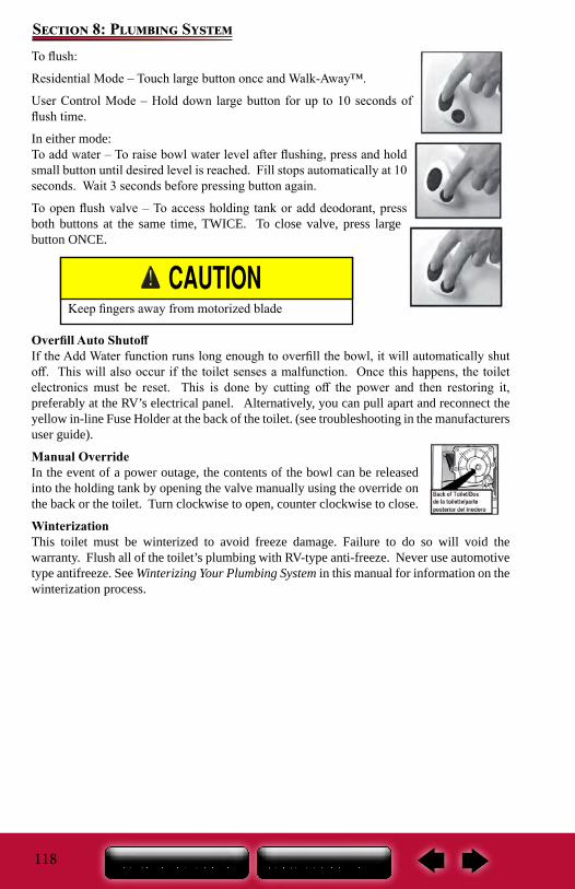
118
Section 8: Plumbing SystemTo flush:
Residential Mode – Touch large button once and Walk-Away™.
User Control Mode – Hold down large button for up to 10 seconds of flush time.
In either mode:To add water – To raise bowl water level after flushing, press and hold small button until desired level is reached. Fill stops automatically at 10 seconds. Wait 3 seconds before pressing button again.
To open flush valve – To access holding tank or add deodorant, press both buttons at the same time, TWICE. To close valve, press large button ONCE.
Overfill Auto ShutoffIf the Add Water function runs long enough to overfill the bowl, it will automatically shut off. This will also occur if the toilet senses a malfunction. Once this happens, the toilet electronics must be reset. This is done by cutting off the power and then restoring it, preferably at the RV’s electrical panel. Alternatively, you can pull apart and reconnect the yellow in-line Fuse Holder at the back of the toilet. (see troubleshooting in the manufacturers user guide).
Manual OverrideIn the event of a power outage, the contents of the bowl can be released into the holding tank by opening the valve manually using the override on the back or the toilet. Turn clockwise to open, counter clockwise to close.
WinterizationThis toilet must be winterized to avoid freeze damage. Failure to do so will void the warranty. Flush all of the toilet’s plumbing with RV-type anti-freeze. Never use automotive type antifreeze. See Winterizing Your Plumbing System in this manual for information on the winterization process.
Keep fingers away from motorized blade
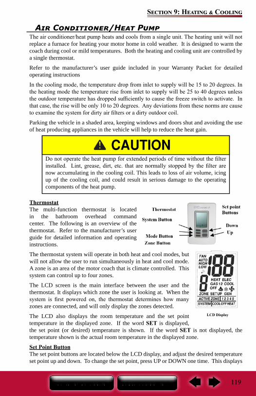
119
Section 9: Heating & Cooling
Air Conditioner/Heat PumpThe air conditioner/heat pump heats and cools from a single unit. The heating unit will not replace a furnace for heating your motor home in cold weather. It is designed to warm the coach during cool or mild temperatures. Both the heating and cooling unit are controlled by a single thermostat.
Refer to the manufacturer’s user guide included in your Warranty Packet for detailed operating instructions
In the cooling mode, the temperature drop from inlet to supply will be 15 to 20 degrees. In the heating mode the temperature rise from inlet to supply will be 25 to 40 degrees unless the outdoor temperature has dropped sufficiently to cause the freeze switch to activate. In that case, the rise will be only 10 to 20 degrees. Any deviations from these norms are cause to examine the system for dirty air filters or a dirty outdoor coil.
Parking the vehicle in a shaded area, keeping windows and doors shut and avoiding the use of heat producing appliances in the vehicle will help to reduce the heat gain.
ThermostatThe multi-function thermostat is located in the bathroom overhead command center. The following is an overview of the thermostat. Refer to the manufacturer’s user guide for detailed information and operating instructions.
The thermostat system will operate in both heat and cool modes, but will not allow the user to run simultaneously in heat and cool mode. A zone is an area of the motor coach that is climate controlled. This system can control up to four zones.
The LCD screen is the main interface between the user and the thermostat. It displays which zone the user is looking at. When the system is first powered on, the thermostat determines how many zones are connected, and will only display the zones detected.
The LCD also displays the room temperature and the set point temperature in the displayed zone. If the word SET is displayed, the set point (or desired) temperature is shown. If the word SET is not displayed, the temperature shown is the actual room temperature in the displayed zone.
Set Point ButtonThe set point buttons are located below the LCD display, and adjust the desired temperature set point up and down. To change the set point, press UP or DOWN one time. This displays
Do not operate the heat pump for extended periods of time without the filter installed. Lint, grease, dirt, etc. that are normally stopped by the filter are now accumulating in the cooling coil. This leads to loss of air volume, icing up of the cooling coil, and could result in serious damage to the operating components of the heat pump.
LCD Display
120
Section 9: Heating & Cooling
the word SET, and puts the system in the mode to change the set point. Then each press of the UP or DOWN buttons changes the set point up or down for the displayed zone by one degree per press of the button.
Set points are not adjustable: When the thermostat is turned off. For the displayed zone when the zone is set to run “FAN HIGH” or “FAN LOW” . If the displayed zone is turned “OFF”.
Set points are stored permanently in memory for each zone in both heating and cooling. This allows the user to switch between heating and cooling at season changes and maintain the same settings from the previous year.
System ButtonThe SYSTEM button is used to put the thermostat into either heating or cooling modes, or turning the thermostat off. Selecting OFF, the system will not operate any heating or cooling appliances, but will still display the room temperature in each zone.
Select HEAT, and the heating appliance selected will operate when the zone room temperature is one degree below the desired set point temperature. The heating appliance will continue to run until the zone temperature is one degree above the desired set point temperature.
Selecting COOL, and the cooling appliance connected in the particular zone will operate according to the mode the zone is set to.
Zone Button: By pressing the ZONE button, the user can toggle through to each zone. Mode Button: By pressing the MODE button the user toggles through the different modes for the system. When in COOL the thermostat will toggle through the following modes: “COOL AUTO”, “COOL HIGH”, “COOL LOW”, “FAN HIGH”, “and FAN LOW”, “OFF”.
When in HEAT, the thermostat will toggle through the following modes: “GAS HEAT”, “HEAT ELEC”, “OFF”. However this will only happen if the system has both gas and electric heat in a zone.
If a system has only an air conditioner and gas furnace in a zone, then when set to heat, the user will only be able to toggle through “GAS HEAT” and “OFF” because there is no electric heat available.
Setting the Thermostat:The thermostat default setting for each zone upon initial startup is 78°F, for cooling and 68°F, for heating. The fan speed for the cooling mode is “COOL AUTO”, which is set to vary the fan speed according to the cooling needs. The fan speed for the heating mode is dependent on the type of heat that is installed for each zone and can not be changed.
Setting Temperature1. Use the SYSTEM button to select either COOL or HEAT. The current room temperature
for that zone will display.2. Press the MODE button to select the operation you desire.3. Press the SET POINT buttons (UP or DOWN) once to place the thermostat in the SET
mode. At this point the thermostat displays the current set point for the displayed zone. (SET will show on the LCD display)
4. Press the SET POINT buttons (UP or DOWN) to change the set point temperature to the desired setting. Each press of the UP or DOWN button will change the set point
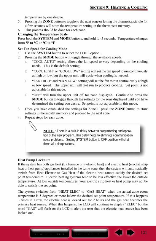
121
Section 9: Heating & Cooling
temperature by one degree. 5. Pressing the ZONE button to toggle to the next zone or letting the thermostat sit idle for
a few seconds will store the temperature setting in the thermostat memory.6. This process should be done for each zone.Changing the Temperature ScalePress both the SYSTEM and MODE buttons, and hold for 5 seconds. Temperature changes from °F to °C or °C to °F
Set Fan Speed for Cooling Mode1. Use the SYSTEM button to select the COOL option.2. Pressing the MODE button will toggle through the available speeds.
“COOL AUTO” setting allows the fan speed to vary depending on the cooling needs. This is the default setting.
“COOL HIGH” or “COOL LOW” setting will set the fan speed to run continuously at high or low, but the upper unit will cycle when cooling is needed.
“FAN HIGH” and “FAN LOW” setting will set the fan to run continuously at high or low speed. The upper unit will not run to produce cooling. Set point is not adjustable in this mode.
“OFF” will turn the upper unit off for zone displayed. Continue to press the MODE button to toggle through the settings for the zone displayed until you have determined the setting you desire. Set point is not adjustable in this mode.
3. Once you have established the settings for Zone 1, press the ZONE button to store settings in thermostat memory and proceed to the next zone.
4. Repeat steps for each zone.
Heat Pump Lockout:If the system has both gas heat (LP furnace or hydronic heat) and electric heat (electric strip heat or heat pump) appliances installed in the same zone, then the system will automatically switch from Heat Electric to Gas Heat if the electric heat cannot satisfy the desired set point temperature. Electric heating systems tend to be less effective the lower the outside temperature. At low outside temperatures, your electric strip heat or heat pump may not be able to satisfy the set point.
The system switches from “HEAT ELEC” to “GAS HEAT” when the actual zone room temperature is 5 degrees or more below the desired set point temperature. If this happens 3 times in a row, the electric heat is locked out for 2 hours and the gas heat becomes the primary heat source. When this happens, the LCD will continue to display “ELEC” but the word “GAS” will flash on the LCD to alert the user that the electric heat source has been locked out.
NOTE: : There is a built-in delay between programming and opera-tion of the new program. This delay helps to eliminate communication noise problems. Setting SYSTEM button to OFF position will shut down all unit operations.
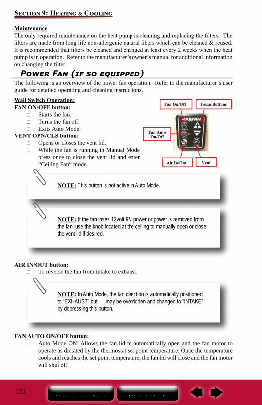
122
Section 9: Heating & Cooling
MaintenanceThe only required maintenance on the heat pump is cleaning and replacing the filters. The filters are made from long life non-allergenic natural fibers which can be cleaned & reused. It is recommended that filters be cleaned and changed at least every 2 weeks when the heat pump is in operation. Refer to the manufacturer’s owner’s manual for additional information on changing the filter.
Power Fan (if so equipped)The following is an overview of the power fan operation. Refer to the manufacturer’s user guide for detailed operating and cleaning instructions.
Wall Switch Operation:FAN ON/OFF button:
Starts the fan. Turns the fan off. Exits Auto Mode.
VENT OPN/CLS button: Opens or closes the vent lid. While the fan is running in Manual Mode
press once to close the vent lid and enter “Ceiling Fan” mode.
AIR IN/OUT button: To reverse the fan from intake to exhaust.
FAN AUTO ON/OFF button: Auto Mode ON: Allows the fan lid to automatically open and the fan motor to
operate as dictated by the thermostat set point temperature. Once the temperature cools and reaches the set point temperature, the fan lid will close and the fan motor will shut off.
NOTE: This button is not active in Auto Mode.
NOTE: If the fan loses 12volt RV power or power is removed from the fan, use the knob located at the ceiling to manually open or close the vent lid if desired.
NOTE: In Auto Mode, the fan direction is automatically positioned to “EXHAUST” but may be overridden and changed to “INTAKE” by depressing this button.
123
Section 9: Heating & Cooling
Pressing this button while in Auto Mode will shut off Auto Mode, close the vent lid and shut off the fan motor.
TEMP Buttons (Up/Down): Temp Up Arrow: To increase the Set Temperature for Auto Mode. Temp Down Arrow: To decrease the Set Temperature for Auto Mode.
SPEED buttons (Up/Down): Fan Speed Up Arrow: Increases the fan speed. The fan has 10 speeds. Fan Speed Down Arrow: Decreases the fan speed. The fan has 10 speeds.
Low Battery Indicator: When the battery is at full charge, three black power bars are displayed. One or zero power bars displayed indicates the batteries need to be replaced.
Transmission Signal Indicator: This symbol is displayed on the screen when any button is pressed to indicate the
signal was transmitted to the fan. A beep sound from the ceiling unit indicates the signal from the remote control
was received by the fan.
NOTE: When the fan speed reaches either the maximum or minimum speed, the fan will respond with 2 quick beep sounds to indicate this.
NOTE: After 5 minutes of inactivity, the LCD screen goes blank to save battery power. Press any button once to turn the LCD screen on.
NOTE: The thermostat ranges from 29°F to 99°F (-2°C to 37°C). To change the display from Fahrenheit to Celsius, press and hold both set temperature keys (Up/Down arrows) simultaneously.
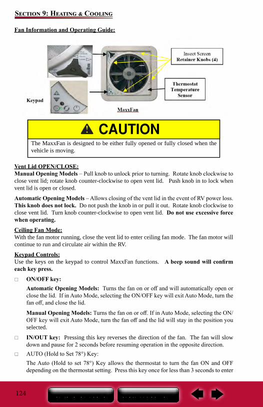
124
Section 9: Heating & Cooling
Fan Information and Operating Guide:
Vent Lid OPEN/CLOSE:Manual Opening Models – Pull knob to unlock prior to turning. Rotate knob clockwise to close vent lid; rotate knob counter-clockwise to open vent lid. Push knob in to lock when vent lid is open or closed.
Automatic Opening Models – Allows closing of the vent lid in the event of RV power loss. This knob does not lock. Do not push the knob in or pull it out. Rotate knob clockwise to close vent lid. Turn knob counter-clockwise to open vent lid. Do not use excessive force when operating.
Ceiling Fan Mode:With the fan motor running, close the vent lid to enter ceiling fan mode. The fan motor will continue to run and circulate air within the RV.
Keypad Controls:Use the keys on the keypad to control MaxxFan functions. A beep sound will confirm each key press.
ON/OFF key:Automatic Opening Models: Turns the fan on or off and will automatically open or close the lid. If in Auto Mode, selecting the ON/OFF key will exit Auto Mode, turn the fan off, and close the lid.
Manual Opening Models: Turns the fan on or off. If in Auto Mode, selecting the ON/OFF key will exit Auto Mode, turn the fan off and the lid will stay in the position you selected.
IN/OUT key: Pressing this key reverses the direction of the fan. The fan will slow down and pause for 2 seconds before resuming operation in the opposite direction.
AUTO (Hold to Set 78°) Key:The Auto (Hold to set 78°) Key allows the thermostat to turn the fan ON and OFF depending on the thermostat setting. Press this key once for less than 3 seconds to enter
The MaxxFan is designed to be either fully opened or fully closed when the vehicle is moving.
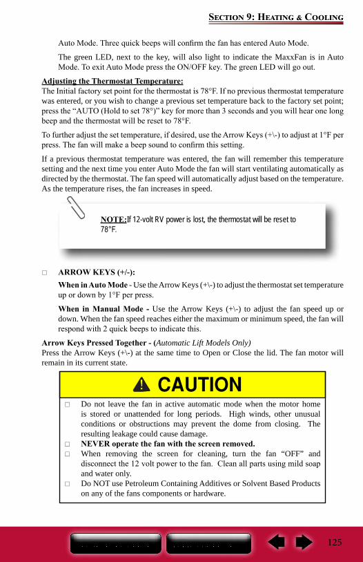
125
Section 9: Heating & Cooling
Auto Mode. Three quick beeps will confirm the fan has entered Auto Mode.
The green LED, next to the key, will also light to indicate the MaxxFan is in Auto Mode. To exit Auto Mode press the ON/OFF key. The green LED will go out.
Adjusting the Thermostat Temperature:The Initial factory set point for the thermostat is 78°F. If no previous thermostat temperature was entered, or you wish to change a previous set temperature back to the factory set point; press the “AUTO (Hold to set 78°)” key for more than 3 seconds and you will hear one long beep and the thermostat will be reset to 78°F.
To further adjust the set temperature, if desired, use the Arrow Keys (+\-) to adjust at 1°F per press. The fan will make a beep sound to confirm this setting.
If a previous thermostat temperature was entered, the fan will remember this temperature setting and the next time you enter Auto Mode the fan will start ventilating automatically as directed by the thermostat. The fan speed will automatically adjust based on the temperature. As the temperature rises, the fan increases in speed.
ARROW KEYS (+/-):When in Auto Mode - Use the Arrow Keys (+\-) to adjust the thermostat set temperature up or down by 1°F per press.
When in Manual Mode - Use the Arrow Keys (+\-) to adjust the fan speed up or down. When the fan speed reaches either the maximum or minimum speed, the fan will respond with 2 quick beeps to indicate this.
Arrow Keys Pressed Together - (Automatic Lift Models Only)Press the Arrow Keys (+\-) at the same time to Open or Close the lid. The fan motor will remain in its current state.
Do not leave the fan in active automatic mode when the motor home is stored or unattended for long periods. High winds, other unusual conditions or obstructions may prevent the dome from closing. The resulting leakage could cause damage.
NEVER operate the fan with the screen removed. When removing the screen for cleaning, turn the fan “OFF” and
disconnect the 12 volt power to the fan. Clean all parts using mild soap and water only.
Do NOT use Petroleum Containing Additives or Solvent Based Products on any of the fans components or hardware.
NOTE:If 12-volt RV power is lost, the thermostat will be reset to 78°F.
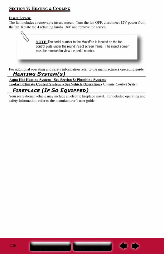
126
Section 9: Heating & Cooling
Insect Screen:The fan includes a removable insect screen. Turn the fan OFF, disconnect 12V power from the fan. Rotate the 4 retaining knobs 180° and remove the screen.
For additional operating and safety information refer to the manufacturers operating guide.
NOTE:The serial number to the MaxxFan is located on the fan control plate under the round insect screen frame. The insect screen must be removed to view the serial number.
Heating System(s)Aqua Hot Heating System - See Section 8; Plumbing SystemsIn-dash Climate Control System - See Vehicle Operation - Climate Control System
Fireplace (If So Equipped)Your recreational vehicle may include an electric fireplace insert. For detailed operating and safety information, refer to the manufacturer’s user guide.
127
Section 10: Appliances
Microwave
For details on operation, cleaning and safety information, refer to the manufacturer’s user guide.
General Cleaning Microwave and Convection MicrowaveIMPORTANT: Before cleaning, make sure all controls are off and the microwave oven is cool. Always follow label instructions on cleaning products.
To avoid damage to the microwave oven caused by arcing due to soil buildup keep cavity, microwave inlet cover, cooking rack supports, and area where the door touches the frame clean.
Clean with mild soap, water and a soft cloth or sponge, or as indicated below.
Grease filters: mild soap and water or dishwasher. Door and exterior: mild soap and water, or glass cleaner applied to paper towel. Control panel: sponge or soft cloth and water. Stainless steel (on some models): mild soap and water, then rinse with clean water and
dry with soft cloth, or use stainless steel cleaner. Turntable: mild soap and water or dishwasher. Rack(s): mild soap, water and washcloth. Dishwasher cleaning is not recommended.
Convection Microwave (if so equipped)The convection microwave bridges the gap between microwaving your food and conventional cooking. Make sure there is sufficient 120-volt power before operating the convection microwave (see Calculating Electrical Load). or details on operation and safety information, refer to the manufacturer’s user guide.
Never use the microwave cavity for storage. The microwave cavity should always be empty when not in use.
To prevent damage, remove the turntable from the microwave when traveling.
Make sure you are connected to a 120-volt power source.
Cooking SafetyIn Case Of a Grease Fire
Grease is flammable. Never allow grease to collect around top burners or on the cook top surface. Wipe up spills immediately. Refer to Section 2 – Safety Precautions, for fire safety and fire extinguisher information.
Do not attempt to use water to put out the fire. Water can spread some types of fire, and electrocution is possible with an electrical fire.
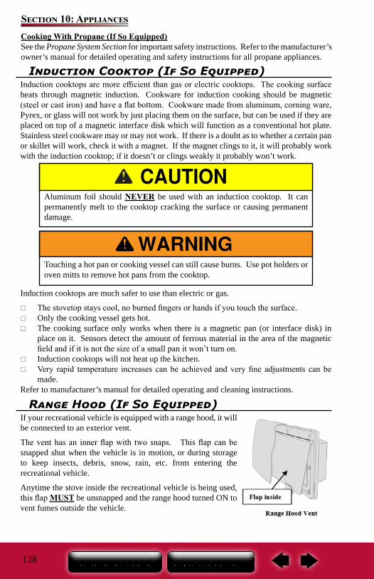
128
Section 10: AppliancesCooking With Propane (If So Equipped)See the Propane System Section for important safety instructions. Refer to the manufacturer’s owner’s manual for detailed operating and safety instructions for all propane appliances.
Induction Cooktop (If So Equipped)Induction cooktops are more efficient than gas or electric cooktops. The cooking surface heats through magnetic induction. Cookware for induction cooking should be magnetic (steel or cast iron) and have a flat bottom. Cookware made from aluminum, corning ware, Pyrex, or glass will not work by just placing them on the surface, but can be used if they are placed on top of a magnetic interface disk which will function as a conventional hot plate. Stainless steel cookware may or may not work. If there is a doubt as to whether a certain pan or skillet will work, check it with a magnet. If the magnet clings to it, it will probably work with the induction cooktop; if it doesn’t or clings weakly it probably won’t work.
Induction cooktops are much safer to use than electric or gas.
The stovetop stays cool, no burned fingers or hands if you touch the surface. Only the cooking vessel gets hot. The cooking surface only works when there is a magnetic pan (or interface disk) in
place on it. Sensors detect the amount of ferrous material in the area of the magnetic field and if it is not the size of a small pan it won’t turn on.
Induction cooktops will not heat up the kitchen. Very rapid temperature increases can be achieved and very fine adjustments can be
made.Refer to manufacturer’s manual for detailed operating and cleaning instructions.
Aluminum foil should NEVER be used with an induction cooktop. It can permanently melt to the cooktop cracking the surface or causing permanent damage.
Touching a hot pan or cooking vessel can still cause burns. Use pot holders or oven mitts to remove hot pans from the cooktop.
Range Hood (If So Equipped)If your recreational vehicle is equipped with a range hood, it will be connected to an exterior vent.
The vent has an inner flap with two snaps. This flap can be snapped shut when the vehicle is in motion, or during storage to keep insects, debris, snow, rain, etc. from entering the recreational vehicle.
Anytime the stove inside the recreational vehicle is being used, this flap MUST be unsnapped and the range hood turned ON to vent fumes outside the vehicle.
129
Section 10: Appliances
Whenever the stove in the RV is being used: The range hood MUST be turned on, and the inner flap MUST be unsnapped and free to move. Failure to do so can create an asphyxiation hazard by restricting air flow to this vent.
Refrigerator
The refrigerator is not intended for quick freezing or cooling. We recommend stocking it with pre-frozen or pre-cooled food when possible. The shelves should not be covered with paper or plastic and the food items should be arranged so air can circulate freely.
Contact your dealer or Customer Service for details on winterizing your refrigerator.
For detailed operating and safety information, refer to the manufacturer’s user guide.
Cleaning Your RefrigeratorThe following are general cleaning guidelines. For detailed information on cleaning your specific refrigerator, refer to the manufacturer’s user’s guide.
Cleaning the interior1. Unplug refrigerator or disconnect power.2. Hand wash, rinse, and dry removable parts and interior surfaces thoroughly. Use a clean
sponge or soft cloth and a mild detergent in warm water.3. Inside the refrigerator, use a warm water and baking soda solution
consisting of approximately 1-tablespoon (15ml) baking soda to 1 quart (1 liter) of water. This solution cleans and neutralizes odors. Rinse and wipe dry.
4. Leave an open box of baking soda in the refrigerator and freezer compartments to help prevent odors.
The ice maker should be turned off and the ice tray emptied when power to your motor home has been shut off. With no power, the ice will melt and water will “pool” in the refrigerator door. When power is restored, the vibration will cause this water to run out of the door and on to the motor home floor.
NOTE: Do not use abrasive or harsh cleaners such as window sprays, scouring cleansers, flammable fluids, cleaning waxes, concentrated detergents, bleaches or cleansers containing petroleum products on plastic parts, interior and door liners or gaskets. Do not use paper towels, scouring pads, or other harsh cleaning tools.
NOTE: Make sure you are connected to a 120-volt power source.
130
Section 10: Appliances
There is no need for routine condenser cleaning in normal operating environments. If the environment is particularly greasy or dusty, or if there is significant pet traffic, the condenser should be cleaned every 2 to 3 months to ensure maximum efficiency.
If you need to clean the condenser: Remove the base grille. Use a vacuum cleaner with a soft brush to clean the grille, the open areas behind the
grille and the front surface area of the condenser. Replace the base grille when finished.
Cleaning the exteriorPainted metal exteriors: wash with a clean sponge or soft cloth and a mild detergent in warm water.
Stainless steel exteriors: wash with a clean sponge or soft cloth and a mild detergent in warm water. Do not use appliance wax, polish, bleach, or other products containing chlorine on stainless steel. Stainless steel can be cleaned with a commercially available stainless steel cleaner. A spray-on stainless steel cleaner works best. IMPORTANT: Do not allow the Stainless Steel Cleaner and Polish to come into contact with any plastic parts such as the trim pieces, dispenser covers or door gaskets.
If unintentional contact does occur, clean plastic part with a sponge and mild detergent in warm water. Dry thoroughly with a soft cloth.For silver-accented plastic parts, wash with soap or other mild detergents. Wipe clean with a sponge or damp cloth. Do not use scouring pads, powdered cleaners, bleach or cleaners containing bleach as these products can scratch and weaken the paint finish.
Dishwasher (if so equipped)The following is an overview of the drawer dishwasher operation. For details on operation, cleaning and safety information, refer to the manufacturer’s user guide.
1. Load dishes – Remove all food scraps and load the dishes.2. Add detergent. Check rinse aid.3. Press the power button4. Select a wash program – The length of the wash program will appear on the electronic
display (models with LCD only).5. Select ECO (optional)6. Check – Ensure there is nothing obstructing the spray arm. The drain filter must be
level with the filter plate.7. Start – Close the drawer and press the II button.8. Finish – Six “beeps” indicates the end of the wash program. At the end of the wash
program, the drying fan will continue to run for a set time or until the drawer is opened. It is normal for some water to remain in the drain filter area after the program is complete.
Contact your Dealer or Customer Service for details on sanitizing and winterizing.
Washer/Dryer (if so equipped)If your motor home is equipped with a stackable washer/dryer set, make sure you have sufficient power available before operating the washer or dryer (refer to calculating electrical load). Make sure you are connected to a 120-volt power source.
Refer to the manufacturer owner’s manual included in your Owner’s Portfolio for detailed safety, operating and care instructions.
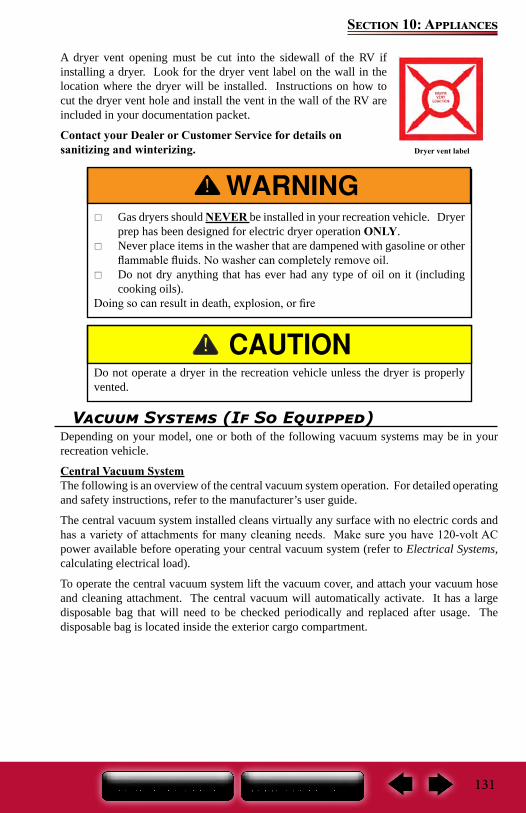
131
Section 10: Appliances
A dryer vent opening must be cut into the sidewall of the RV if installing a dryer. Look for the dryer vent label on the wall in the location where the dryer will be installed. Instructions on how to cut the dryer vent hole and install the vent in the wall of the RV are included in your documentation packet.
Contact your Dealer or Customer Service for details on sanitizing and winterizing. Dryer vent label
Gas dryers should NEVER be installed in your recreation vehicle. Dryer prep has been designed for electric dryer operation ONLY.
Never place items in the washer that are dampened with gasoline or other flammable fluids. No washer can completely remove oil.
Do not dry anything that has ever had any type of oil on it (including cooking oils).
Doing so can result in death, explosion, or fire
Do not operate a dryer in the recreation vehicle unless the dryer is properly vented.
Vacuum Systems (If So Equipped)Depending on your model, one or both of the following vacuum systems may be in your recreation vehicle.
Central Vacuum SystemThe following is an overview of the central vacuum system operation. For detailed operating and safety instructions, refer to the manufacturer’s user guide.
The central vacuum system installed cleans virtually any surface with no electric cords and has a variety of attachments for many cleaning needs. Make sure you have 120-volt AC power available before operating your central vacuum system (refer to Electrical Systems, calculating electrical load).
To operate the central vacuum system lift the vacuum cover, and attach your vacuum hose and cleaning attachment. The central vacuum will automatically activate. It has a large disposable bag that will need to be checked periodically and replaced after usage. The disposable bag is located inside the exterior cargo compartment.
132
Section 10: Appliances
Rechargeable Vacuum The portable vacuum is equipped with a rechargeable battery pack that can be plugged into a 120V AC wall outlet. Refer to manufacturer’s user guide for important safeguards and operating instructions. Read all instructions before operating the vacuum cleaner.
DO NOT PICK UP ANYTHING THAT IS BURNING OR SMOKING, SUCH AS CIGARETTES, MATCHES, OR HOT ASHES. RV damage, personal injury, or death may result from vacuuming up burning or smoking material.
DO NOT PICK UP FLAMMABLE OR COMBUSTIBLE LIQUIDS SUCH AS GASOLINE, OR USE IN AREAS WHERE THEY MAY BE PRESENT. RV damage, personal injury, or death may result from vacuuming up flammable or combustible material
133
Section 11: Electronics
Antenna/Satellite System(s)Your motor home may be equipped with one or more of the following:
Satellite TV Antenna (if so equipped)The stationary and/or in-motion satellite TV antenna enables you to toggle between satellites while stationary or in-motion using a remote control (if you subscribe to multi-satellite programming).
The following is an overview of the satellite operation and functions. Refer to the manufacturer’s user guide for detailed operating instructions.
Your unit is preset for DIRECTV receivers. To change this setting, refer to the manufacturer’s operation manual.
Operating your in-motion antenna 1. Turn on receiver and television set. The antenna must be connected to a receiver that
is plugged into 12 VAC.2. Verify that you are getting the receiver’s menu screens on the television. These
screens are available with or without the dish finding the signal. Refer to the antenna manufacturer’s operation manual for details of receiver set up.
3. Turn the power switch on for the antenna. The dish should start moving, making one or two revolutions before it stops to acquire GPS. This can take a few moments or up to 10-15 minutes. Normal operation will be less than a minute.
4. Once the unit has acquired GPS, the dish will begin its search. The dish will pause on the signal long enough to determine which satellite it has found. If it moves off the signal, it is in an effort to verify the signal and should return to the signal shortly.
5. After the unit has verified that it has the correct satellite, it will continue to track the signal.
6. If the vehicle does not move for six minutes, the unit will toggle to its alternate satellite, then toggle back to the primary satellite and “go to sleep”. If the vehicle begins movement in a straight line at 10 mph, the unit will resume tracking mode.
7. If you do not have a signal, see “Troubleshooting” during power up in the manufacturer’s operation manual.
Modes of OperationWhether stationary or in-motion during satellite signal acquisition, the unit enters tracking mode. In this mode, the unit will actively follow the satellite as the vehicle travels, even if the vehicle is stationary for the first six minutes. Tracking mode ends when the antenna has finished its search and the vehicle has not moved for six (6) minutes. The antenna will resume tracking mode if it detects movement in a straight line at 10 mph or more.
In sleep mode, the unit is at rest. The antenna enters sleep mode six (6) minutes after a successful search if stationary, or six (6) minutes after the vehicle stops moving.
NOTE: All dome satellite systems are motorized single dish / single LNB mechanisms. They can only point toward and receive program-ming from one satellite at a time. The automatic satellite dish is compatible with DISH Network® and DIRECTV® standard definition programming and DISH Network HD programming.
134
Section 11: Electronics
Recovery from Signal InterruptionWhile traveling, the signal will be interrupted when the line of sight to the satellite is blocked. Signal is acquired again after line of sight is restored. If signal is interrupted for more than 15 seconds, the system automatically enters the search routine. The length of time for the TV picture to recover depends on the receiver model you are using.
Toggle In-MotionThe satellite antenna will automatically toggle between the primary and alternate satellites for your service provider. For toggling in-motion, you may notice a slight delay in satellite switching which could cause a loss in picture. This is normal.
Picture loss should be no longer than three seconds. If the alternate satellite the antenna is trying to toggle to is blocked for more than 25 seconds, the system automatically enters the search routine.
Operating your SD (stationary) antenna1. Turn on receiver and television set. The antenna must be connected to a receiver
that is plugged into 120 VAC.2. Verify that you are getting the receiver’s menu screens on the television. These
screens are available with or without the dish finding the signal.3. Turn the power switch on for the antenna. The dish will detect if it is already on a
satellite signal. If it detects a signal, the dish will move to check its alternate satellite and then move back to the original satellite signal that is on.
4. If no signal was detected, the dish will begin its search to locate the primary satellite. Once the dish locates a signal, it will pause long enough to identify which satellite it has located. This may or may not be visible on your receiver’s point dish screen.
5. After the unit has verified that it has the correct satellite, it will move to check the alternate satellite and move back to the primary satellite to complete the search routine.
6. If you do not have signal, see Troubleshooting in the manufacturer’s owner’s manual.
NOTE: You must drive in a straight line at 10 mph or more when starting to operate in motion.
NOTE: Use your on-screen guide to locate your channel rather than “channel surfing”. This will result in smoother operation.
NOTE: Because the antenna uses information from the last location that it was on a signal, satellite acquisition may take longer if the dish is inactive over long distance traveling.
135
Section 11: Electronics
DIRECTV must be set to the “two” satellite, oval dish setting. Refer to your receiver manual. DISH Network receivers must have the check switch set to “SW64”.Satellite Dish (if so equipped)The following is an overview of the automatic multi satellite TV antenna operation. For detailed operating instructions, including receiver set up, refer to the manufacturer’s user guide.
When you press “POWER,” the antenna will automatically begin searching for satellites. The instructions assume that the antenna is already in the stowed position.
1. Press and hold “POWER” for two seconds or until the TRAV’LER interface displays “POWER ON.” Once the unit has been powered on, release “POWER.
2. The interface screen will display the type of satellite dish on the top line.3. The antenna will enter the search mode as part of its normal operation and will display
“Searching” on the bottom line.4. The antenna will find its home position and begin to look for a satellite. Upon finding a
satellite, the antenna will fine-tune or “peak” on the signal.5. In automatic search mode, the antenna will lock onto three different satellites: 99°,
101°, and 103°. The antenna will display an asterisk for each satellite found.If the receiver is already set up in the RV, you are now ready to watch TV
Before traveling, make sure to press “POWER” and wait for the antenna to start to power up; then press “POWER” again to initiate the stow sequence. See below for information on stowing before traveling.
User Menu for Manual OperationThe interface includes a user menu for some advanced features. The options most commonly used are the ability to change the dish type, check software/hardware versions, change desired satellite configuration, or manually move the dish.
The antenna is not meant for use while traveling. To stow the unit for travel, press “POWER” one time. The unit will stop what it is doing and return to the stowed position. The interface will not turn off unless the antenna is successfully stowed. Visually inspect that the antenna is in the stowed/travel position before traveling. Do not move the vehicle until the antenna is stowed.
Emergency Manual StowIf unable to stow the antenna, it may be necessary to use emergency manual stow. Emergency manual stow is meant as a last resort and is not meant for common usage! To use emergency
NOTE: If you want to turn off the power to the antenna after it has locked onto satellites, press “POWER” and “SELECT” at the same time.
Improper use of the user menu could cause damage to the antenna and/or vehicle. Do not enter the user menu for regular operation.
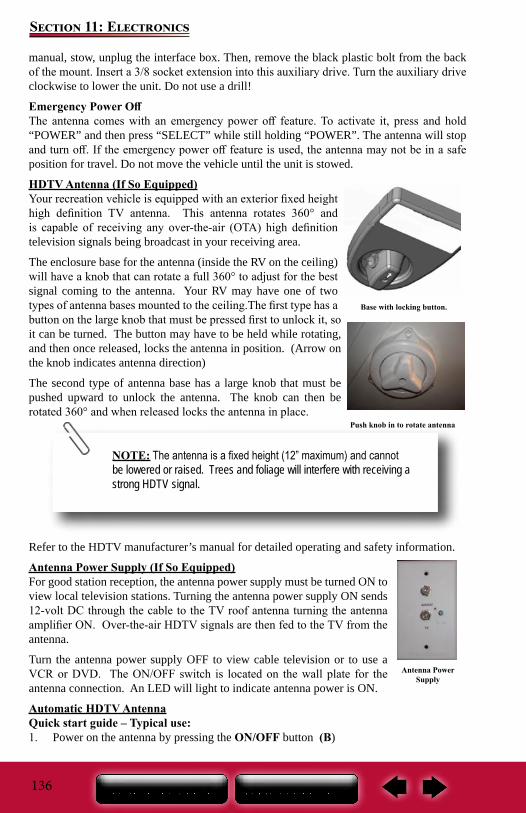
136
Section 11: Electronics
manual, stow, unplug the interface box. Then, remove the black plastic bolt from the back of the mount. Insert a 3/8 socket extension into this auxiliary drive. Turn the auxiliary drive clockwise to lower the unit. Do not use a drill!
Emergency Power OffThe antenna comes with an emergency power off feature. To activate it, press and hold “POWER” and then press “SELECT” while still holding “POWER”. The antenna will stop and turn off. If the emergency power off feature is used, the antenna may not be in a safe position for travel. Do not move the vehicle until the unit is stowed.
HDTV Antenna (If So Equipped)Your recreation vehicle is equipped with an exterior fixed height high definition TV antenna. This antenna rotates 360° and is capable of receiving any over-the-air (OTA) high definition television signals being broadcast in your receiving area.
The enclosure base for the antenna (inside the RV on the ceiling) will have a knob that can rotate a full 360° to adjust for the best signal coming to the antenna. Your RV may have one of two types of antenna bases mounted to the ceiling.The first type has a button on the large knob that must be pressed first to unlock it, so it can be turned. The button may have to be held while rotating, and then once released, locks the antenna in position. (Arrow on the knob indicates antenna direction)
The second type of antenna base has a large knob that must be pushed upward to unlock the antenna. The knob can then be rotated 360° and when released locks the antenna in place.
Refer to the HDTV manufacturer’s manual for detailed operating and safety information.
Antenna Power Supply (If So Equipped)For good station reception, the antenna power supply must be turned ON to view local television stations. Turning the antenna power supply ON sends 12-volt DC through the cable to the TV roof antenna turning the antenna amplifier ON. Over-the-air HDTV signals are then fed to the TV from the antenna.
Turn the antenna power supply OFF to view cable television or to use a VCR or DVD. The ON/OFF switch is located on the wall plate for the antenna connection. An LED will light to indicate antenna power is ON.
Automatic HDTV AntennaQuick start guide – Typical use:1. Power on the antenna by pressing the ON/OFF button (B)
Base with locking button.
NOTE: The antenna is a fixed height (12” maximum) and cannot be lowered or raised. Trees and foliage will interfere with receiving a strong HDTV signal.
Push knob in to rotate antenna
Antenna Power Supply
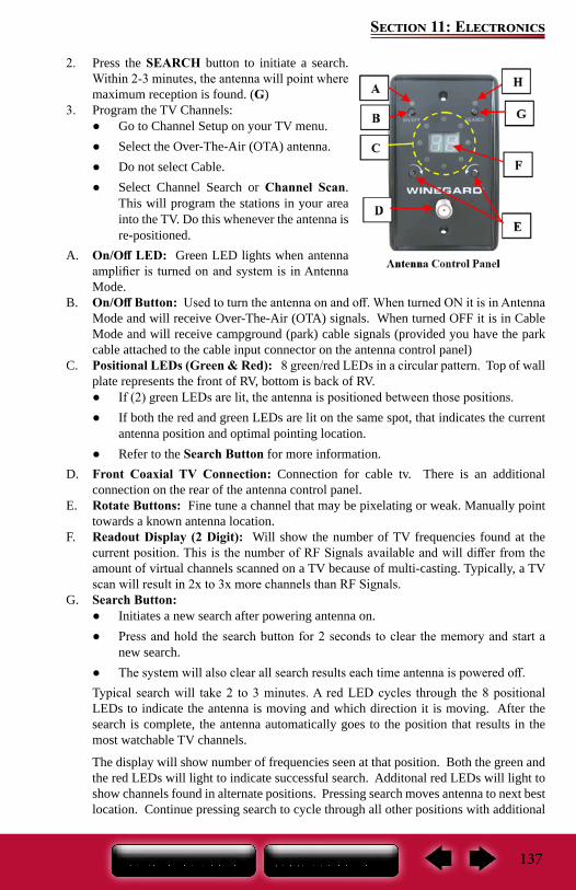
137
Section 11: Electronics
2. Press the SEARCH button to initiate a search. Within 2-3 minutes, the antenna will point where maximum reception is found. (G)
3. Program the TV Channels: ● Go to Channel Setup on your TV menu. ● Select the Over-The-Air (OTA) antenna. ● Do not select Cable. ● Select Channel Search or Channel Scan.
This will program the stations in your area into the TV. Do this whenever the antenna is re-positioned.
A. On/Off LED: Green LED lights when antenna amplifier is turned on and system is in Antenna Mode.
B. On/Off Button: Used to turn the antenna on and off. When turned ON it is in Antenna Mode and will receive Over-The-Air (OTA) signals. When turned OFF it is in Cable Mode and will receive campground (park) cable signals (provided you have the park cable attached to the cable input connector on the antenna control panel)
C. Positional LEDs (Green & Red): 8 green/red LEDs in a circular pattern. Top of wall plate represents the front of RV, bottom is back of RV.
● If (2) green LEDs are lit, the antenna is positioned between those positions. ● If both the red and green LEDs are lit on the same spot, that indicates the current
antenna position and optimal pointing location. ● Refer to the Search Button for more information.
D. Front Coaxial TV Connection: Connection for cable tv. There is an additional connection on the rear of the antenna control panel.
E. Rotate Buttons: Fine tune a channel that may be pixelating or weak. Manually point towards a known antenna location.
F. Readout Display (2 Digit): Will show the number of TV frequencies found at the current position. This is the number of RF Signals available and will differ from the amount of virtual channels scanned on a TV because of multi-casting. Typically, a TV scan will result in 2x to 3x more channels than RF Signals.
G. Search Button: ● Initiates a new search after powering antenna on. ● Press and hold the search button for 2 seconds to clear the memory and start a
new search. ● The system will also clear all search results each time antenna is powered off.
Typical search will take 2 to 3 minutes. A red LED cycles through the 8 positional LEDs to indicate the antenna is moving and which direction it is moving. After the search is complete, the antenna automatically goes to the position that results in the most watchable TV channels.
The display will show number of frequencies seen at that position. Both the green and the red LEDs will light to indicate successful search. Additonal red LEDs will light to show channels found in alternate positions. Pressing search moves antenna to next best location. Continue pressing search to cycle through all other positions with additional
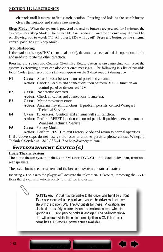
138
Section 11: Electronics
channels until it returns to first search location. Pressing and holding the search button clears the memory and starts a new search.
Sleep Mode: When the system is powered on, and no buttons are pressed for 3 minutes the system enters Sleep Mode. The power LED will remain lit and the antenna amplifier will be on allowing you to watch TV. All other LEDs will be off. Press any button on the antenna control panel to exit Sleep Mode.
TroubleshootingIf the readout displays “HS” (in manual mode), the antenna has reached the operational limit and needs to rotate the other direction.
Pressing the Search and Counter Clockwise Rotate button at the same time will reset the system. Performing a reset can also clear error messages. The following is a list of possible Error Codes (and resolutions) that can appear on the 2-digit readout during use.
E1 Cause: Short in coax between control panel and antenna Action: Check all cables and connections then perform RESET function on control panel or disconnect 12V.E2 Cause: No antenna detected Action: Check all cables and connections to antenna.E3 Cause: Motor movement error Action: Antenna may still function. If problem persists, contact Winegard Technical Service.E4 Cause: Tuner error. Controls and antenna will still function. Action: Perform RESET function on control panel. If problem persists, contact Winegard Technical Service.E5 Cause: Factory Mode. Action: Perform RESET to exit Factory Mode and return to normal operation.If the above steps do not resolve the issue or another persists, please contact Winegard Technical Service at 1-800-788-4417 or [email protected].
Entertainment Center(s)Home Theater SystemThe home theater system includes an FM tuner, DVD/CD, iPod dock, television, front and rear speakers.
The coach home theater system and the bedroom system operate separately.
Inserting a DVD into the player will activate the television. Likewise, removing the DVD from the player will automatically turn off the television.
NOTE: Any TV that may be visible to the driver whether it be a front TV or one mounted in the bunk area above the driver, will not oper-ate with the ignition ON. The AC outlets for these TV locations are disabled as a safety feature. Normal operation resumes when the ignition is OFF and parking brake is engaged. The bedroom televi-sion will operate while the motor home ignition is ON if the motor home has a 120-volt AC power source available.
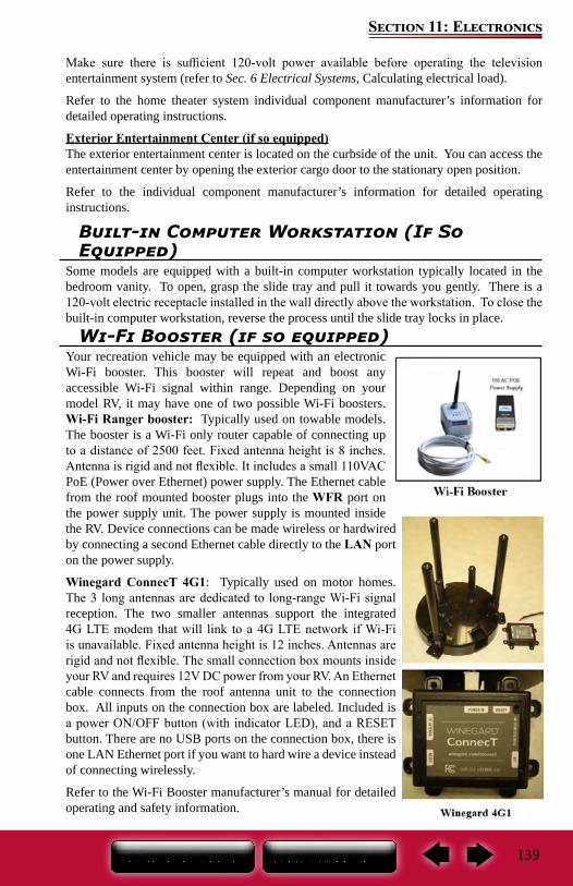
139
Section 11: Electronics
Make sure there is sufficient 120-volt power available before operating the television entertainment system (refer to Sec. 6 Electrical Systems, Calculating electrical load).
Refer to the home theater system individual component manufacturer’s information for detailed operating instructions.
Exterior Entertainment Center (if so equipped)The exterior entertainment center is located on the curbside of the unit. You can access the entertainment center by opening the exterior cargo door to the stationary open position.
Refer to the individual component manufacturer’s information for detailed operating instructions.
Built-in Computer Workstation (If So Equipped)
Some models are equipped with a built-in computer workstation typically located in the bedroom vanity. To open, grasp the slide tray and pull it towards you gently. There is a 120-volt electric receptacle installed in the wall directly above the workstation. To close the built-in computer workstation, reverse the process until the slide tray locks in place.
Wi-Fi Booster (if so equipped)Your recreation vehicle may be equipped with an electronic Wi-Fi booster. This booster will repeat and boost any accessible Wi-Fi signal within range. Depending on your model RV, it may have one of two possible Wi-Fi boosters.Wi-Fi Ranger booster: Typically used on towable models. The booster is a Wi-Fi only router capable of connecting up to a distance of 2500 feet. Fixed antenna height is 8 inches. Antenna is rigid and not flexible. It includes a small 110VAC PoE (Power over Ethernet) power supply. The Ethernet cable from the roof mounted booster plugs into the WFR port on the power supply unit. The power supply is mounted inside the RV. Device connections can be made wireless or hardwired by connecting a second Ethernet cable directly to the LAN port on the power supply.
Winegard ConnecT 4G1: Typically used on motor homes. The 3 long antennas are dedicated to long-range Wi-Fi signal reception. The two smaller antennas support the integrated 4G LTE modem that will link to a 4G LTE network if Wi-Fi is unavailable. Fixed antenna height is 12 inches. Antennas are rigid and not flexible. The small connection box mounts inside your RV and requires 12V DC power from your RV. An Ethernet cable connects from the roof antenna unit to the connection box. All inputs on the connection box are labeled. Included is a power ON/OFF button (with indicator LED), and a RESET button. There are no USB ports on the connection box, there is one LAN Ethernet port if you want to hard wire a device instead of connecting wirelessly.
Refer to the Wi-Fi Booster manufacturer’s manual for detailed operating and safety information.

140
Section 11: Electronics
Notes:
141
Section 12: Interior
Cleaning The InteriorTo keep the value of your recreation vehicle, perform regular maintenance using the proper materials and procedures. Using the wrong cleaner may result in damage to the surfaces in your vehicle. Check with the manufacturer’s information for the recommended cleaning agent. If in doubt, check to see if the cleaner will cause damage by testing a small area out of sight or contact your dealer for assistance. Do not use flammable liquids or sprays to clean the recreation vehicle.
Décor Glass (if so equipped)Use a glass cleaner to remove smudges, smears and spots. If there is decorative etching on the décor glass, use care when cleaning around that area.
Furniture UpholsteryTo retain the value of your recreation vehicle, maintain the furniture upholstery carefully and keep the interior clean. Vacuum the furniture regularly using a soft brush attachment to remove any loose dirt or debris.
Fabric (if so equipped)It is recommended the fabric be professionally cleaned if it becomes stained or soiled. The professional cleaner should be made aware the fabrics that may have been treated to be fire resistant. For more information, refer to the specific furniture manufacturer’s care instructions.
Ultraleather™ (if so equipped): It is recommended the Ultraleather™ be professionally cleaned if it becomes stained or soiled. For more information, refer to the specific furniture manufacturer’s care instructions.
Leather (if so equipped): Periodic vacuuming, using a dry cloth to wipe up spills immediately, and using a damp cloth on problem areas, will help to keep your leather furniture in good condition. Leather surfaces can vary, as do the cleaning methods. Refer to the furniture manufacturer’s recommendation, or consult a cleaning professional.
It is recommended you do not use any cleaners containing oils, waxes or silicones. Cleaners containing silicone can eventually destroy the finish on the leather. Cleaners containing oils or waxes should not be used as they leave residues on the surface of the leather which can attract more dirt which can eventually lead to cracking
Window Treatments Fabric – Drapes and valances: Dust occasionally with a vacuum and soft brush attachment. It is recommended the fabric be professionally cleaned if it becomes stained or soiled. The professional cleaner should be made aware the fabrics that may have been treated to be fire resistant.
Window ShadesShades should be vacuumed periodically to remove dust. It doesn’t matter what type of shade or fabric you have, using your vacuum cleaners upholstery brush on low suction will remove most dust and dirt from the shade. Refer to the shade manufacturer’s owner’s manual for additional and detailed information.
To remove stuck on dust or stains refer to the following guide.
Solar shields: Use a sponge or soft brush and water to remove stains. A mild cleaning solution can be used to remove tougher stains. Rinse after cleaning by wetting a clean cloth in fresh water, wringing our any excess and wiping the areas where the cleaner was used.
142
Section 12: Interior
Day/night Shades: Clean with a mild cleaning solution using a sponge or paper towel. Wipe down with water after cleaning and dry thoroughly before raising the shade. Do not use spot remover, household cleaners or detergents to remove soiled spots, as these may cause damage to fabric or loss of color from fading.
Mini Blinds: A simple dry rag may do the trick. If they are especially dirty, you can use cold or warm water to clean them; never use hot water.
Fill a spray bottle with water and a tiny amount of soap. Then spray a lint-free towel with the mixture and use the towel to wipe down each slat. While cleaning, try not to bend the slats. They can also be soaked in a bathtub to loosen up any debris so the slats can be wiped down easily.
Roller Shades: Can be easily cared for by simply using soapy water or a mild cleaning solution on spots. However try a small area first. Harsh household cleaners or detergents may cause damage to fabric or loss of color. It is our recommendation to dust the rails and fabrics of the shades on a regular basis. Shades should be kept in the closed or up position when not in use, to maintain pleat retention and minimize dirt and soil build-up. Do not store shades in the down position. This may cause some loss of pleat retention if the shades are not operated on a consistent basis.
Cabinetry & TablesTo keep hardwood doors, cabinet fronts and hardwood tables looking like new regularly dust with a soft cloth dampened with a cleaning polish or mild detergent solution. Avoid using ammonia based products or silicone oils as they may cause damage if used over a long period of time.
The finish is durable and resistant to most household spills. However, spills should be wiped up promptly to avoid potential problems. Excessive prolonged exposure to direct sunlight, high temperatures and high humidity can cause damage to both the finish and the wood itself. These should be avoided.
Interior Wall PanelPlease contact your dealership service department for assistance in repairing décor paneling. If deep scratches occur on the wall panel, putty sticks can be used to cover scratches on wood surfaces. These can be obtained from local hardwood stores and lumberyards.
To clean, use a mild solution of soap and lukewarm water with a soft sponge or cloth. Wipe dry with a soft, clean cloth.
Do not use abrasive cleaners as they may cause the vinyl to scratch and become dull. Do not use cleaners that contain bleach
NOTE: If your recreation vehicle must be stored for an extended period of time, store shades in the up position and cover your win-dows with additional protection (I.E. Cut out cardboard).
143
Section 12: Interior
ABS PlasticsDust and wipe clean with soft, damp cloth or chamois, wiping gently. Do not use gritty or abrasive particle soaps or scouring compound to clean ABS plastic. Avoid using “citrus” or biodegradable cleaners that contain “D-Limonene” as they may damage plastic materials.
Sofa & Dinette
Your motor home may be equipped with one of the following sofa styles.
Easy Bed SofaThe easy bed sofa should comfortably seat two to three adults. It converts to a bed by lifting at the front of the sofa seat section and pulling it towards you. The sofa back will follow and pivot down into a horizontal position. To reconvert back to an upright sofa, reverse the process (make sure to pull the seat belts out into their usable positions). Refer to the furniture manufacturer’s care instructions for this product.
Hide-A-Bed SofaThe hide-a-bed sofa functions much the same as a regular residential hide-a-bed sofa. To make the hide-a-bed sofa into a bed, remove the seat cushions and pull the strap located at the front of the sofa seat bottom out towards you firmly and gently.
To convert the hide-a-bed back into the upright sofa position, reverse the process (make sure to pull the seat belts out into their usable positions). Be sure to hold the sofa strap firmly to ensure the hide-a-bed sofa does not suddenly drop shut. Refer to the furniture manufacturer’s care instructions for this product.
Love SeatThe love seat adds to your motor home seating capacity. It should seat up to two adults comfortably. Refer to the specific furniture manufacturer’s care instructions for this product.
Dinette TableThe dinette table can be extended by standing at the end of the table, firmly holding both sides of the table, and pulling the table towards you. To return the table to the stowed position, reverse this process pushing it in until the table locks in place.
Free Standing Dinette Chairs (If So Equipped)Two free standing chairs and two folding chairs are included in the Free Standing Table/chair Package (if so equipped). When traveling in the motor home, it is recommended the free standing dinette chairs be fastened securely at the dinette table, and the folding chairs be secured in a closet or storage area.
Always use seatbelts if sitting in the sofa or dinette while the motor home is in transit
Do not allow occupants to occupy the free standing dinette chairs while the motor home is in transit.
144
Section 12: Interior
Pantry or Hutch (If So Equipped)Your recreation vehicle may have a pantry or hutch that you can use for storage. Make sure all items stored in the pantry or hutch are secured to prevent shifting during travel. This cabinetry has been designed to accommodate the normal camping items which may be bulky but not necessarily heavy. Remember your recreation vehicle’s load capacity is designed by weight, not volume, so you cannot necessarily use all available space.
If your pantry or hutch has sliding pantry shelves, they have been equipped with a locking mechanism to keep them in place during transit. To secure the shelf in place, push it all of the way in until the latch tab clicks into place. Always pull out slightly on the shelf to make sure that it is stationary and secure in the transit position. To release the shelf, push in on the tab and pull the shelf slowly towards you.
Your RV’s load capacity is designated by weight, not by volume, so you cannot necessarily use all available space when loading the vehicle. Do not exceed your GVWR and ensure you are loading the vehicle as evenly as you can for the best possible handling. Ensure heavy items are secured so they do not shift during travel.
Convertible Table (If So Equipped)
Care should be taken when tilting the table top; keep fingers clear to avoid getting caught or pinched in the locking system.
Table is intended for typical table use, it is NOT intended to be used as a seat.
Don’t overtighten the round feet. Tile can be cracked if feet are overtightened.
Ensure the round feet are in the “up” position (tight to the brackets) whenever assembling or disassembling the table; or when retracting or extending the slideout room.
DO NOT SLAM THE TABLE! The locking pin must be released by pulling the strap and holding, while locking the table top down.
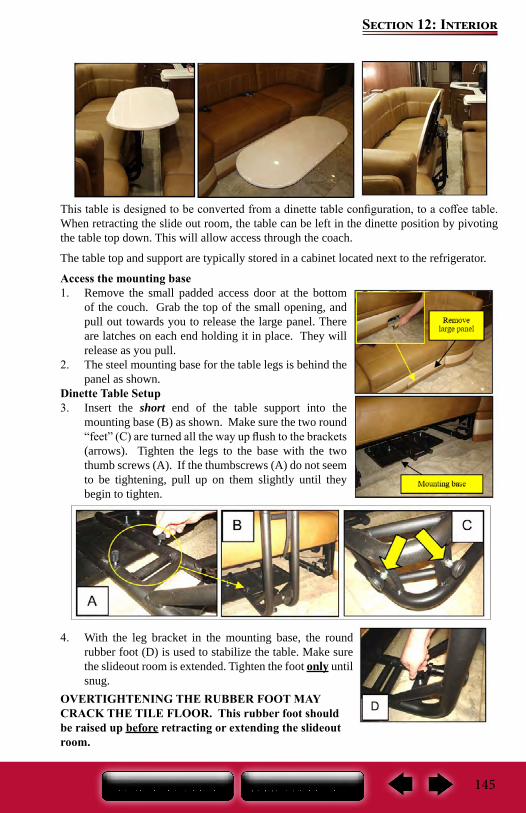
145
Section 12: Interior
This table is designed to be converted from a dinette table configuration, to a coffee table. When retracting the slide out room, the table can be left in the dinette position by pivoting the table top down. This will allow access through the coach.
The table top and support are typically stored in a cabinet located next to the refrigerator.
Access the mounting base1. Remove the small padded access door at the bottom
of the couch. Grab the top of the small opening, and pull out towards you to release the large panel. There are latches on each end holding it in place. They will release as you pull.
2. The steel mounting base for the table legs is behind the panel as shown.
Dinette Table Setup3. Insert the short end of the table support into the
mounting base (B) as shown. Make sure the two round “feet” (C) are turned all the way up flush to the brackets (arrows). Tighten the legs to the base with the two thumb screws (A). If the thumbscrews (A) do not seem to be tightening, pull up on them slightly until they begin to tighten.
4. With the leg bracket in the mounting base, the round rubber foot (D) is used to stabilize the table. Make sure the slideout room is extended. Tighten the foot only until snug.
OVERTIGHTENING THE RUBBER FOOT MAY CRACK THE TILE FLOOR. This rubber foot should be raised up before retracting or extending the slideout room.
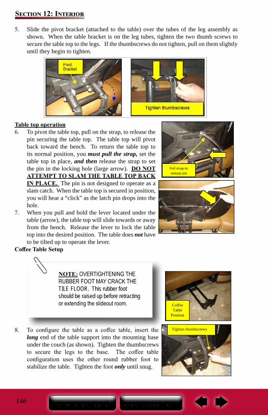
146
Section 12: Interior
5. Slide the pivot bracket (attached to the table) over the tubes of the leg assembly as shown. When the table bracket is on the leg tubes, tighten the two thumb screws to secure the table top to the legs. If the thumbscrews do not tighten, pull on them slightly until they begin to tighten.
Table top operation6. To pivot the table top, pull on the strap, to release the
pin securing the table top. The table top will pivot back toward the bench. To return the table top to its normal position, you must pull the strap, set the table top in place, and then release the strap to set the pin in the locking hole (large arrow). DO NOT ATTEMPT TO SLAM THE TABLE TOP BACK IN PLACE. The pin is not designed to operate as a slam catch. When the table top is secured in position, you will hear a “click” as the latch pin drops into the hole.
7. When you pull and hold the lever located under the table (arrow), the table top will slide towards or away from the bench. Release the lever to lock the table top into the desired position. The table does not have to be tilted up to operate the lever.
Coffee Table Setup
8. To configure the table as a coffee table, insert the long end of the table support into the mounting base under the couch (as shown). Tighten the thumbscrews to secure the legs to the base. The coffee table configuration uses the other round rubber foot to stabilize the table. Tighten the foot only until snug.
Pull strap to release pin
Coffee Table
Position
Tighten thumbscrews
NOTE: OVERTIGHTENING THE RUBBER FOOT MAY CRACK THE TILE FLOOR. This rubber foot should be raised up before retracting or extending the slideout room.
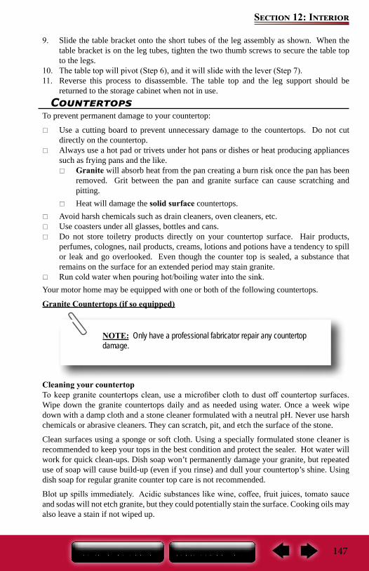
147
Section 12: Interior
9. Slide the table bracket onto the short tubes of the leg assembly as shown. When the table bracket is on the leg tubes, tighten the two thumb screws to secure the table top to the legs.
10. The table top will pivot (Step 6), and it will slide with the lever (Step 7).11. Reverse this process to disassemble. The table top and the leg support should be
returned to the storage cabinet when not in use.Countertops
To prevent permanent damage to your countertop:
Use a cutting board to prevent unnecessary damage to the countertops. Do not cut directly on the countertop.
Always use a hot pad or trivets under hot pans or dishes or heat producing appliances such as frying pans and the like.
Granite will absorb heat from the pan creating a burn risk once the pan has been removed. Grit between the pan and granite surface can cause scratching and pitting.
Heat will damage the solid surface countertops. Avoid harsh chemicals such as drain cleaners, oven cleaners, etc. Use coasters under all glasses, bottles and cans. Do not store toiletry products directly on your countertop surface. Hair products,
perfumes, colognes, nail products, creams, lotions and potions have a tendency to spill or leak and go overlooked. Even though the counter top is sealed, a substance that remains on the surface for an extended period may stain granite.
Run cold water when pouring hot/boiling water into the sink.Your motor home may be equipped with one or both of the following countertops.
Granite Countertops (if so equipped)
Cleaning your countertopTo keep granite countertops clean, use a microfiber cloth to dust off countertop surfaces. Wipe down the granite countertops daily and as needed using water. Once a week wipe down with a damp cloth and a stone cleaner formulated with a neutral pH. Never use harsh chemicals or abrasive cleaners. They can scratch, pit, and etch the surface of the stone.
Clean surfaces using a sponge or soft cloth. Using a specially formulated stone cleaner is recommended to keep your tops in the best condition and protect the sealer. Hot water will work for quick clean-ups. Dish soap won’t permanently damage your granite, but repeated use of soap will cause build-up (even if you rinse) and dull your countertop’s shine. Using dish soap for regular granite counter top care is not recommended.
Blot up spills immediately. Acidic substances like wine, coffee, fruit juices, tomato sauce and sodas will not etch granite, but they could potentially stain the surface. Cooking oils may also leave a stain if not wiped up.
NOTE: Only have a professional fabricator repair any countertop damage.
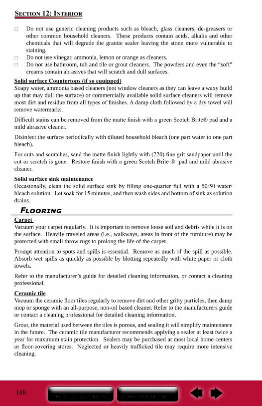
148
Section 12: Interior
Do not use generic cleaning products such as bleach, glass cleaners, de-greasers or other common household cleaners. These products contain acids, alkalis and other chemicals that will degrade the granite sealer leaving the stone more vulnerable to staining.
Do not use vinegar, ammonia, lemon or orange as cleaners. Do not use bathroom, tub and tile or grout cleaners. The powders and even the “soft”
creams contain abrasives that will scratch and dull surfaces.Solid surface Countertops (if so equipped)Soapy water, ammonia based cleaners (not window cleaners as they can leave a waxy build up that may dull the surface) or commercially available solid surface cleaners will remove most dirt and residue from all types of finishes. A damp cloth followed by a dry towel will remove watermarks.
Difficult stains can be removed from the matte finish with a green Scotch Brite® pad and a mild abrasive cleaner.
Disinfect the surface periodically with diluted household bleach (one part water to one part bleach).
For cuts and scratches, sand the matte finish lightly with (220) fine grit sandpaper until the cut or scratch is gone. Restore finish with a green Scotch Brite ® pad and mild abrasive cleaner.
Solid surface sink maintenanceOccasionally, clean the solid surface sink by filling one-quarter full with a 50/50 water/bleach solution. Let soak for 15 minutes, and then wash sides and bottom of sink as solution drains.
FlooringCarpet Vacuum your carpet regularly. It is important to remove loose soil and debris while it is on the surface. Heavily traveled areas (i.e., walkways, areas in front of the furniture) may be protected with small throw rugs to prolong the life of the carpet.
Prompt attention to spots and spills is essential. Remove as much of the spill as possible. Absorb wet spills as quickly as possible by blotting repeatedly with white paper or cloth towels.
Refer to the manufacturer’s guide for detailed cleaning information, or contact a cleaning professional.
Ceramic tileVacuum the ceramic floor tiles regularly to remove dirt and other gritty particles, then damp mop or sponge with an all-purpose, non-oil based cleaner. Refer to the manufacturers guide or contact a cleaning professional for detailed cleaning information.
Grout, the material used between the tiles is porous, and sealing it will simplify maintenance in the future. The ceramic tile manufacturer recommends applying a sealer at least twice a year for maximum stain protection. Sealers may be purchased at most local home centers or floor-covering stores. Neglected or heavily trafficked tile may require more intensive cleaning.
149
Section 12: Interior
DO NOT: Use cleansers containing acid or bleach for routine maintenance. Use wax cleaners, oil-based detergents or sealants to maintain your tile (sealants may
be used on grout joints and natural stone). Use ammonia (it will discolor grout). Use harsh cleaning aids like steel wool pads or scouring pads containing metal. Use a cleaning agent that contains color on unglazed ceramic tile or natural stone.
DO: Test scouring powders on a small area first (not recommended for natural stone). Use a sealer on grout joints. Have any damaged or broken tiles replaced only by a qualified contractor.
Ceiling FabricThe ceiling fabric is made from padded vinyl fabric. Wash with mild detergent and water. Use a soft bristle brush for stubborn soil. Rinse and dry. Some household cleaners and solvents remove plasticizers from vinyl, making them brittle. Abrasive cleaners may mar or scratch the surface. Always test a small hidden area before applying cleaners to the vinyl surface.
Power Window Shades (if so equipped)Power day shades have been installed for the windshield area of your motor home.
To extend the shades, locate the appropriate switch and momentarily press the down arrow on the switch. To retract the shade, momentarily press the up arrow of the switch. Pressing the down or up arrow on the switch a second time will stop shade operation.
NOTE:Operation of front windshield power shades is limited or disabled when the chassis ignition key is turned to the “on” position. This feature prevents unintended shade extension while driving.
Sleep Number® Mattress (if so equipped)For detailed instructions on finding your sleep number, and care information, refer to the manufacturer’s user guide included in the Owner’s Portfolio.
Power Bunk Bed (if so equipped)Your motor home may be equipped with a power bunk bed. The bunk bed may include a wood ladder that hooks on to the side of the bed in order to access the upper bunk. The upper bunk has preset limits as to how far it can be raised and lowered. The lower bunk is fixed in position and does not move. To operate the bed insert the key, and turn it to the ON position. Press the UP or DOWN arrow button. When upper bunk is positioned where you want it, turn the key to the OFF position. Remove the key to prevent accidental movement of the bed.
Do not exceed the weight limit of the bunk ladder or the bunk bed itself. (see Warning information below).
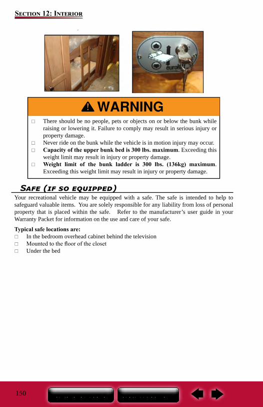
150
Section 12: Interior
Safe (if so equipped)Your recreational vehicle may be equipped with a safe. The safe is intended to help to safeguard valuable items. You are solely responsible for any liability from loss of personal property that is placed within the safe. Refer to the manufacturer’s user guide in your Warranty Packet for information on the use and care of your safe.
Typical safe locations are: In the bedroom overhead cabinet behind the television Mounted to the floor of the closet Under the bed
There should be no people, pets or objects on or below the bunk while raising or lowering it. Failure to comply may result in serious injury or property damage.
Never ride on the bunk while the vehicle is in motion injury may occur. Capacity of the upper bunk bed is 300 lbs. maximum. Exceeding this
weight limit may result in injury or property damage. Weight limit of the bunk ladder is 300 lbs. (136kg) maximum.
Exceeding this weight limit may result in injury or property damage.
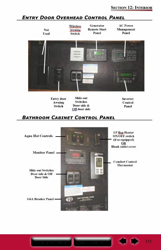
151
Section 12: Interior
Entry Door Overhead Control Panel
Bathroom Cabinet Control Panel

152
Section 12: Interior
Notes:
153
Section 13: Exterior
Cleaning The ExteriorTo protect your motor home’s exterior finish, wash it often and thoroughly. If desired, you may wash and wax your new motor home 60 days after purchase. The exterior paint does need time to cure before any wax is applied to the exterior surface. Careful maintenance for the first 60 days will assure a long lasting durable finish.
Your RV is exposed to many environmental conditions that have an adverse affect on the paint finish:
Road Salt and Sodium Chloride Road Tar / Bugs Bird Droppings / Tree Sap Industrial Fallout / Acid Rain /Pollution UV Exposure and Moisture
The most common problems resulting from these conditions are corrosion, staining, and chemical spotting. Generally, the longer the foreign material remains in contact with the exterior finish, the more extensive the damage. These problems can be minimized by regularly scheduled washing and polishing. Wash your motor home as soon as possible if it becomes contaminated with foreign material.
Avoid parking under trees or near ocean sea salt. Ice or snow should not be scraped from the painted surface: Brush off!
Gravel roads should be avoided.
Anti-freeze, gasoline or washer solvents if spilled on the painted surface should be rinsed off with water immediately. Bugs and bird droppings should be rinsed off daily.
The use of a protective covering (bra) is not recommended and will void the limited lifetime warranty of the diamond shield protective surface (see Cleaning the Diamond Shield Surface).
WashingCommercial washing should be avoided. Wash with cold water using a mild liquid soap. Dry wiping with a dry cloth is not recommended.
Make sure the RV’s surface temperature is cool, under 90 F, and out of direct sunlight. A shaded area is ideal for washing your vehicle as direct sunlight causes water spotting. Use a mild soap, detergent or car wash shampoo. Try to avoid combination wash-n-wax products as these waxes can cause build up and are designed for smaller surfaces. Have two dedicated sponges or wash mitts: one for the paint finish and one for the wheels and under carriage. Brushes or wash mitts made of plastic bristles are acceptable for use on tires and wheel wells, but are not intended for use on the paint finish. Avoid using such items on painted surfaces as they will damage the RV finish. Wash the wheels and wheel wells first as this removes heavy dirt and debris and prevents it from splattering on panels. Wet the entire area down to remove loose dirt and grime, then hand wash one area at a time using your dedicated paint finish sponge or wash mitt. Wash from the top and work your way down, rinsing frequently to minimize grit abrasion. Follow with a final rinse of water. This process will remove most contamination from the RV’s surface.
For stubborn stains such as road tar or bug stains, use an ammonia based glass cleaner or a small amount of rubbing alcohol on a damp cloth followed immediately by warm soapy water, and rinsing with clean water. This may not dissolve the road tar, but it will loosen tar and bug stains and remove them from the surface.
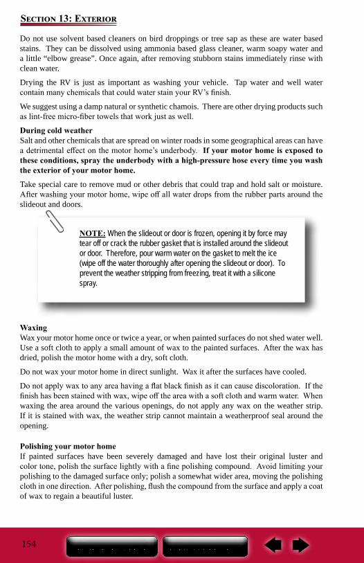
154
Section 13: Exterior
Do not use solvent based cleaners on bird droppings or tree sap as these are water based stains. They can be dissolved using ammonia based glass cleaner, warm soapy water and a little “elbow grease”. Once again, after removing stubborn stains immediately rinse with clean water.
Drying the RV is just as important as washing your vehicle. Tap water and well water contain many chemicals that could water stain your RV’s finish.
We suggest using a damp natural or synthetic chamois. There are other drying products such as lint-free micro-fiber towels that work just as well.
During cold weatherSalt and other chemicals that are spread on winter roads in some geographical areas can have a detrimental effect on the motor home’s underbody. If your motor home is exposed to these conditions, spray the underbody with a high-pressure hose every time you wash the exterior of your motor home.
Take special care to remove mud or other debris that could trap and hold salt or moisture. After washing your motor home, wipe off all water drops from the rubber parts around the slideout and doors.
WaxingWax your motor home once or twice a year, or when painted surfaces do not shed water well. Use a soft cloth to apply a small amount of wax to the painted surfaces. After the wax has dried, polish the motor home with a dry, soft cloth.
Do not wax your motor home in direct sunlight. Wax it after the surfaces have cooled.
Do not apply wax to any area having a flat black finish as it can cause discoloration. If the finish has been stained with wax, wipe off the area with a soft cloth and warm water. When waxing the area around the various openings, do not apply any wax on the weather strip. If it is stained with wax, the weather strip cannot maintain a weatherproof seal around the opening.
Polishing your motor homeIf painted surfaces have been severely damaged and have lost their original luster and color tone, polish the surface lightly with a fine polishing compound. Avoid limiting your polishing to the damaged surface only; polish a somewhat wider area, moving the polishing cloth in one direction. After polishing, flush the compound from the surface and apply a coat of wax to regain a beautiful luster.
NOTE: When the slideout or door is frozen, opening it by force may tear off or crack the rubber gasket that is installed around the slideout or door. Therefore, pour warm water on the gasket to melt the ice (wipe off the water thoroughly after opening the slideout or door). To prevent the weather stripping from freezing, treat it with a silicone spray.
155
Section 13: Exterior
Damaged paintTo prevent corrosion, touch up small cracks and scratches in the paint coat as soon as possible with touch-up film or paint. Carefully check the body areas facing the road and the tires for damage to the paint coat caused by flying stones, etc.
Cleaning the Diamond Shield surfaceYour motor home is equipped with a protective Diamond Shield surface located on the front lower cap area, hood edges, generator door, under the entry door grab handle and door lock. When cleaning the surface, do not use harsh or abrasive cleaners or detergents.
The manufacturer of the Diamond Shield surface does not recommend the use of any of the dry wash types of cleaners as they are intended for non-porous surfaces, paint protection films are a porous material. Car wash type soap is recommended. Bugs should be washed off as soon as possible. One bug cleaner recommended by Diamond Shield is Bug Magic, but any similar product should work just as well.
Use EXTREME care if using a pressure washer, too high of a pressure or misuse of pressure washer may cut or tear the film. Pressure washer damage IS NOT covered under Diamond Shield’s warranty. The application of ANY products over Diamond Shield such as vinyl bras, banners, etc. will void the Diamond Shield warranty.
Diamond Shield recommends the use of 303 Aerospace Protectant™, especially before any trips or Protect All (www.protectall.com). Both of these products replenish and provide UV screening protection, repel dust, soiling and staining, and should be applied every time you clean the front of your motor home. For minor scuffs Diamond Shield recommends the NOVUS line of products. Waxing of your motor home is recommended at least 3-4 times per year. Prior to putting your motor home in storage, the Diamond Shield surface should be cleaned and waxed. Diamond Shield recommends Mothers or Maguire’s Liquid wax. DO NOT USE wax designed for specific colors.
Cleaning plastic partsUse a sponge or chamois to clean plastic parts. Use warm water and a soft cloth or chamois to remove any white residue from dark colored plastic surfaces. Do not use a scrubbing brush, other hard tools, or wax containing abrasives as they may damage the plastic surface.
Chrome partsTo prevent chrome parts from spotting or corroding, wash with water, dry thoroughly, and apply a non-abrasive automotive wax. If the chrome is severely damaged or pitted, use a commercially available chrome polish product.
Do not use waxes containing high-abrasive compounds. Such waxes remove rust and stains effectively from the paint work, but they are also harmful to the luster of the painted surface since they scrape off the coating. Further, they are detrimental to glossy surfaces, such as the grille, garnish, moldings, etc. Do not use gasoline or paint thinners to remove road tar or other contamination to the painted surface.
Do not use a buffer and a buffing compound as it may damage the exterior surface. Please contact a professional paint body shop for assistance.
156
Section 13: Exterior
NOTE: A road test by the dealer should be included as part of the pre-delivery inspection. The dealer can check for and correct any steering problems before you take delivery of the motor home. After this road test has been completed, front-end alignment and/or vibra-tions will not be covered as part of the new vehicle limited warranty.
NOTE: Always have the alignment checked and adjusted by a qualified shop with the proper equipment to handle heavy vehicles.
The mud flap(s) should never be tilted towards the exhaust pipe when the motor home is not in motion or when the motor home is moving in reverse. Caution should be used when parking the motor home to assure the mud flap does not become caught or hung up on stationary items on the ground. This could result in damage to the mud flap(s)
FrameFrames will show signs of rust much sooner when exposed to salty air than in dry air. Also, frames receive heavy abuse from road conditions such as sand, pebbles, objects in the highway, and/or ice inhibiting chemicals, all of which will cause chipping and a blasting effect on the painted surface. Periodically rinse off the frame (or as use requires) removing road grime, tar, oil, mud or salt.
Refer to your Chassis Guide for the chassis manufacturer’s maintenance instructions.
Mud Flap (If so Equipped)If your motor home is equipped with rear wheel mud flaps and a deluxe full-width mud flap, periodically check and remove dirt or debris buildup from the mud flaps.
Front Axle Tire AlignmentThe term alignment refers to both the adjustment angles on the steering axle and suspension and tracking of the rear axle. Many factors are considered when establishing proper alignment. Steering components, suspension, wheel bearings and even proper loading will affect your motor home alignment. Your motor home chassis was aligned by the manufacturer, and weighed at our facility before shipment to your dealer. It is your responsibility to have the alignment inspected periodically to maintain vehicle steering performance and prevent uneven tire wear as part of your normal maintenance.
Do not allow plastic to come into contact with brake fluid, engine oil, grease, paint thinner, or battery acid. These will damage plastic. Use a soft cloth and a mild detergent solution to wipe away any such contact.
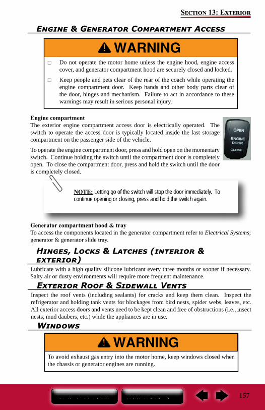
157
Section 13: Exterior
Engine & Generator Compartment Access
Engine compartmentThe exterior engine compartment access door is electrically operated. The switch to operate the access door is typically located inside the last storage compartment on the passenger side of the vehicle.
To operate the engine compartment door, press and hold open on the momentary switch. Continue holding the switch until the compartment door is completely open. To close the compartment door, press and hold the switch until the door is completely closed.
Generator compartment hood & trayTo access the components located in the generator compartment refer to Electrical Systems; generator & generator slide tray.
Do not operate the motor home unless the engine hood, engine access cover, and generator compartment hood are securely closed and locked.
Keep people and pets clear of the rear of the coach while operating the engine compartment door. Keep hands and other body parts clear of the door, hinges and mechanism. Failure to act in accordance to these warnings may result in serious personal injury.
NOTE: Letting go of the switch will stop the door immediately. To continue opening or closing, press and hold the switch again.
Hinges, Locks & Latches (interior & exterior)
Lubricate with a high quality silicone lubricant every three months or sooner if necessary. Salty air or dusty environments will require more frequent maintenance.
To avoid exhaust gas entry into the motor home, keep windows closed when the chassis or generator engines are running.
Windows
Exterior Roof & Sidewall VentsInspect the roof vents (including sealants) for cracks and keep them clean. Inspect the refrigerator and holding tank vents for blockages from bird nests, spider webs, leaves, etc. All exterior access doors and vents need to be kept clean and free of obstructions (i.e., insect nests, mud daubers, etc.) while the appliances are in use.
158
Section 13: Exterior
SealantsSealants perform a very important function and should be inspected closely and regularly maintained. We incorporate many different types of sealants, including butyl/putty, black Butyl-encapsulated foam, silicone (clear and colored), roof sealant and foam. In general, sealants do not have “set” lifetimes.
You or your dealer must: Inspect all sealants, a minimum of every six months. A quick walk around the motor
home before leaving may help prevent potential problems during trips and vacations. Have the sealant replaced if you notice any cracks, voids, gaps, breaks, looseness or
any sign of physical deterioration. Always use the same type of sealant that was removed. Your dealer service or parts
manager can help you obtain the correct sealant(s).The sealants may become damaged due to ultraviolet exposure, air pollution, freezing temperatures and exposure to other elements. If deteriorated, repair immediately to prevent damage. Cap seal all trim and openings at least once after the first year and thereafter as cracks, peeling, lifting and shrinkage occur. Conditions such a as rain, salt, dust and pollution may increase your vehicle maintenance needs.
To check the exterior sidewall sealants, use a stepladder placed safely alongside the vehicle. Do not prop a ladder against the body of the motor home as it may damage the exterior finish
Any ventilating window may permit water inside, especially during heavy rainstorms or while driving. This is normal and water should only be seen in the lower track portion of the window frame. Condensation will also cause water to accumulate on windows and in the tracks. Ensure that the escape window latches are properly adjusted (the window will pop open if not adjusted tight enough).
Window glassThe window glass can normally be cleaned with a sponge and water. Use glass cleaner to remove wax, oil, grease, dead insects, etc. After washing the glass, wipe it dry with a clean, soft cloth.
159
Section 14: Travel/Camping/Storage Checklists
Travel ChecklistFollowing is a preliminary list of items that need to be checked before leaving your home or campsite. This is a general list, which you may want to customize as you determine your own needs. Refer to your Chassis Guide for information on chassis pre-trip inspections and maintenance.
Safety Make sure you follow all safety precautions noted in this owner’s manual and in any
manufacturer’s operators manual when preparing to travel.Before leaving home (or campsite)
Make sure all fluids are at proper levels (engine oil, transmission fluid, engine coolant, power steering fluid and windshield washer fluid).
Check the fuel gauge and lights on the motor home. Have someone observe the operation of all exterior lights while you activate the controls. Check the turn signal and high beam indicators on the instrument panel.
Examine the tires for excessive tread wear or uneven wear patterns. Check for stones, nails, glass or other objects lodged in the tread. Inspect for tread cuts or sidewall cracks.
Check tire pressure and correct according to manufacturer specifications. Check wheel nuts for tightness. Inspect and work all interior and exterior latches and locks (lube if necessary). Make sure the batteries are fully charged and installed correctly. Turn ON the motor home 12-volt battery disconnect switch. Inspect the power cord and carefully clean the contacts if necessary. Plug in the power
cord to an appropriate power source. Turn on the interior lights and check outlets for polarity. If needed, replace any blown
fuses. Check the circuit breakers and test the GFCI circuits. Inspect and turn on the propane gas system (if so equipped). If you have any
questions, contact your independent dealer or a qualified propane gas service representative for assistance. If the propane system is functioning properly, test any pilot lights or direct spark ignition features.
Inspect and test all safety detectors. If needed, replace any drained or discharged batteries. If you have a defective or damaged safety detector, replace it immediately.
Inspect the leveling jacks for operation. If needed, perform maintenance as per the manufacturer’s information.
Test all exterior and interior lights. Replace any bulbs that are burnt out. Prepare the chassis portion of the motor home for the camping season in
accordance with the Chassis Guide. Wash the exterior of the motor home. Do a sealant inspection and repair as necessary. De-winterize and sanitize system. If you are towing a vehicle, connect it to the motor home and test all connections
and lights.Test brakes for proper operation. Fill the fresh water tank. Disconnect, drain and store the garden hose on the bracket. Check the seat belt buckles and release mechanisms for positive action and secure
connections.Before leaving the campsite
Check the area under the motor home after overnight parking and look for fuel, water, oil or other fluid leaks. If leaks are detected, find the cause and correct it immediately.
Turn off propane tanks (if so equipped).
160
Section 14: Travel/Camping/Storage Checklists
Empty black and gray holding tank, rinse as needed. Retract any awnings and secure them for transport. Close all the roof vents. Close windows & latch blinds. Disconnect the cable TV and phone hookups and lower the TV antenna. Turn off the interior lights, water heater, furnace and water pump. Secure any loose, heavy or sharp objects in the motor home or exterior compartments. Disconnect the power cord and ensure it is stored correctly. Disconnect any water connections. Water pump and water heater (if applicable) turned off. Fasten all interior and exterior doors securely. Lock them (if applicable) Latch drawers,
cabinets & doors. Move slideout(s) in and lock it in place (if applicable). Walk around your motor home one last time to make sure everything is stored away and
the baggage compartments are closed and locked. Refrigerator door locked. Furnace turned off. Make sure the leveling jacks are retracted to the travel position. Retract step. Secure and lock the entrance door.
Motor home StorageProperly preparing your motor home for storage during periods of non-usage will prevent problems from arising. It will also make it easier to get started again for the following camping trip or season. To prevent costly freeze-ups, winterize the plumbing system when it will not be in use for an extended period of time, especially if it is stored in colder climates.
Prior to storage Prepare the chassis for storage in accordance to the Chassis Guide. Remember to use
fuel additives and supplements if recommended. Wash and wax the exterior of the vehicle. Do a sealant inspection and repair as
necessary. Inspect and clean tires. Check for wear, cracks and inflation pressure. Inspect and seal off any area that offers an entry point for rodents, birds or insects.
Cover all external outlets (i.e. furnace, vents etc.). Damage from birds, rodents, insect, etc., is not covered under the “Motorized Transferable Limited Warranty” applicable to your motor home.
Close all windows, roof vents and range hood vent. Turn the furnace thermostat(s) to the OFF position. If your motor home is equipped with a gas/electric DSI range, light a range gas burner
to consume any gas remaining in the lines. Once the flame extinguishes itself, turn the burner valve OFF.
Drain all water lines. Make sure the motor home is winterized Winterize the toilet and appliances (dishwasher, refrigerator, clothes washer) Drain and flush all holding tanks (fresh water, gray water, black water and/or hot water
tanks). Adding fuel stabilizer to the generator will aid in preventing condensation and fuel
varnishing. Turn OFF the motor home 12-volt battery disconnect switch. Turn OFF the inverter mode at remote.
161
Section 14: Travel/Camping/Storage Checklists
Disconnect the batteries to prevent battery discharge. Remove all perishables from the refrigerator/freezer. Defrost, wash and dry the interior
of the refrigerator/freezer and prop (or block) the doors open so air can circulate and prevent mildew.
Remove all perishables from the cabinets. Leave the cabinets and doors ajar to allow air circulation and prevent mildew and musty odors.
Lubricate locks and hinges on exterior doors.While the motor home is being storedIf the vehicle is stored outside in areas of heavy snow, you should periodically brush the snow off to prevent excessive accumulation and prevent possible roof damage.
Quick Start GuideCamp Setup / Tear DownWhen setting up camp, please follow these steps:
Before plugging into shore power, turn off the breaker at the campsite post. Extend the slide out rooms (always check for proper clearance first). Make sure tires are straight. Extend jacks after slide out rooms are extended.
When packing and leaving camp, please follow these steps: Start engine to build air pressure. (Use high idle-cruise on and hold resume). Retract jacks to inflate air bags. Check for tire clearance. Retract slide outs after unit has reached standard ride height. Lock all appliance doors. Turn off breaker at campsite post before unplugging unit.
While traveling, please keep these in mind: Make sure the main power switch is turned on. If traveling with food, turn the inverter on to use the refrigerator. Remember to turn the
inverter off before storing unit or when not in use. You should only have to use the generator if you want to use roof A/C units. The engine alternator will maintain the house batteries during travel.
Entegra Coach Emergency Contact InformationMonday – Friday: (800) 517-9137 (8 AM – 5 PM)
After Hours Emergency: (574) 361-0034
Comfort Control SettingsZone Classification
Zone 1 Front A/C on “cool” Front heat pump on heat “electric” Heat exchangers – at dash, kitchen base, and hutch/entertainment center base on
heat “gas” Zone 2
Middle A/C on “cool” Middle heat pump on heat “electric” In-floor heat, on heat “gas”
Zone 3 Rear A/C on “cool” Rear heat pump on heat “electric” Heat exchangers – at rear wall and under lavatory sink on heat “gas”
162
Section 14: Travel/Camping/Storage Checklists
Basement – one heat exchanger on rear basement wall, thermostat located on top passenger side of rear basement wall
Entertainment Center Set-UpEntegra satellite wiring is set up for two options:
1. Install receiver at main TV utilizing the HDMI output on the wall plate. This signal will then be distributed to all four TVs on HDMI 2. You may also place a second receiver in the bedroom connected directly to that TV.
2. Install receiver at main TV and utilize coax output to the selector box. This will also provide satellite to all TVs through the selector box.
All TVs will have off-air antenna and park-cable capabilities.
Overall DimensionsHeight: 12’ 11” Width: 101”
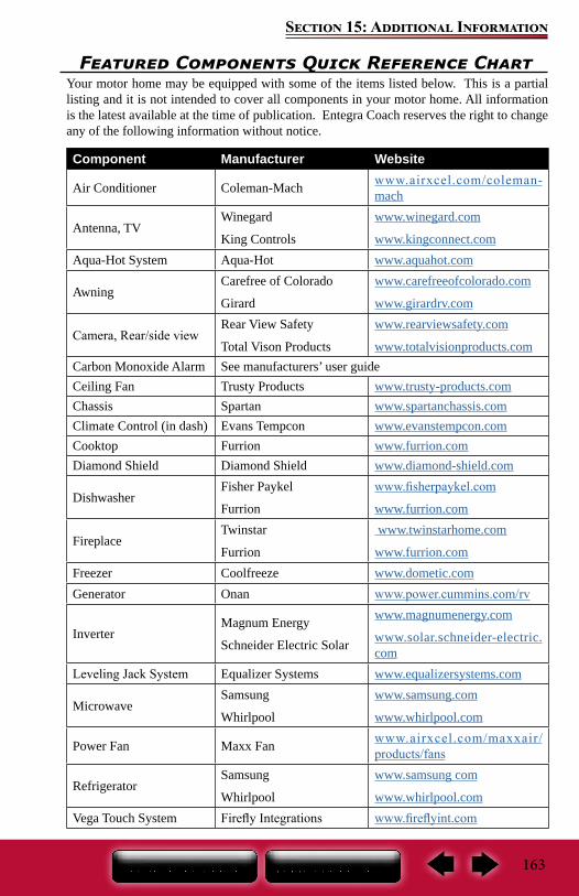
163
Section 15: Additional Information
Featured Components Quick Reference ChartYour motor home may be equipped with some of the items listed below. This is a partial listing and it is not intended to cover all components in your motor home. All information is the latest available at the time of publication. Entegra Coach reserves the right to change any of the following information without notice.
Component Manufacturer Website
Air Conditioner Coleman-Mach www.airxcel.com/coleman-mach
Antenna, TVWinegard
King Controls
www.winegard.com
www.kingconnect.comAqua-Hot System Aqua-Hot www.aquahot.com
AwningCarefree of Colorado
Girard
www.carefreeofcolorado.com
www.girardrv.com
Camera, Rear/side viewRear View Safety
Total Vison Products
www.rearviewsafety.com
www.totalvisionproducts.comCarbon Monoxide Alarm See manufacturers’ user guideCeiling Fan Trusty Products www.trusty-products.comChassis Spartan www.spartanchassis.comClimate Control (in dash) Evans Tempcon www.evanstempcon.comCooktop Furrion www.furrion.comDiamond Shield Diamond Shield www.diamond-shield.com
DishwasherFisher Paykel
Furrion
www.fisherpaykel.com
www.furrion.com
FireplaceTwinstar
Furrion
www.twinstarhome.com
www.furrion.comFreezer Coolfreeze www.dometic.comGenerator Onan www.power.cummins.com/rv
InverterMagnum Energy
Schneider Electric Solar
www.magnumenergy.com
www.solar.schneider-electric.com
Leveling Jack System Equalizer Systems www.equalizersystems.com
MicrowaveSamsung
Whirlpool
www.samsung.com
www.whirlpool.com
Power Fan Maxx Fan www.airxcel.com/maxxair/products/fans
RefrigeratorSamsung
Whirlpool
www.samsung com
www.whirlpool.comVega Touch System Firefly Integrations www.fireflyint.com
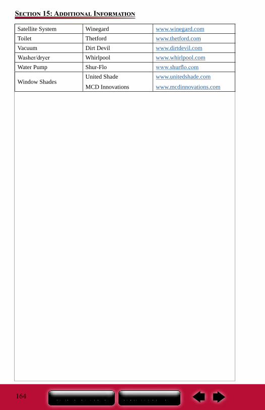
164
Section 15: Additional Information
Satellite System Winegard www.winegard.comToilet Thetford www.thetford.comVacuum Dirt Devil www.dirtdevil.comWasher/dryer Whirlpool www.whirlpool.comWater Pump Shur-Flo www.shurflo.com
Window ShadesUnited Shade
MCD Innovations
www.unitedshade.com
www.mcdinnovations.com
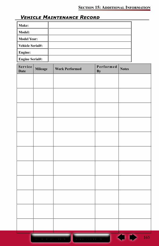
165
Section 15: Additional Information
Vehicle Maintenance RecordMake:
Model:
Model Year:
Vehicle Serial#:
Engine:
Engine Serial#:
Service Date Mileage Work Performed Per formed
By Notes

166
Section 15: Additional Information
Service Date Mileage Work Performed Per formed
By Notes
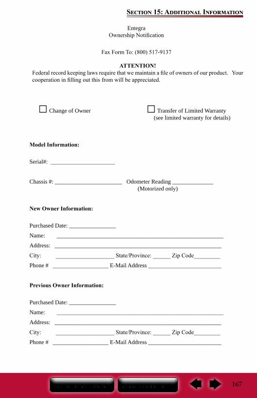
167
Section 15: Additional Information
EntegraOwnership Notification
Fax Form To: (800) 517-9137
□ Change of Owner □ Transfer of Limited Warranty (see limited warranty for details)
Model Information:
Serial#: ______________________
Chassis #: _______________________ Odometer Reading ______________ (Motorized only)
New Owner Information:
Purchased Date: ________________
Name: _________________________________________________________
Address: _________________________________________________________
City: ____________________ State/Province: ______ Zip Code_________
Phone # ___________________ E-Mail Address _________________________
Previous Owner Information:
Purchased Date: ________________
Name: _________________________________________________________
Address: _________________________________________________________
City: ____________________ State/Province: ______ Zip Code_________
Phone # ___________________ E-Mail Address _________________________
ATTENTION!Federal record keeping laws require that we maintain a file of owners of our product. Your cooperation in filling out this from will be appreciated.