Embed Size (px)
Citation preview


- 1 -
ACKNOWLEDGEMENT
We fold our hands to the almighty for making this magazine Instrue v5.0 a reality. We are
thankful to Dr.S. Thamaraiselvi, the Dean, MIT for providing a platform to bring about this
magazine. We are grateful to our Head Dr.J. Prakash for his trust and support in the outcome
of the magazine. We thank Professor Emeritus Dr.P. Kanagasabapathy, who was the
instrument in initiating the magazine. All the staff members have been a great pillar of
support and strength throughout, to the entire magazine team. We are obliged to them. We
ought to express our gratitude to the alumni for the helping hand.
We thank and appreciate all our student friends without whom ‗INSTRUE‘ would have just
been a dream.
- Team Instrue
Disclaimer: The written and visual contents of this magazine are known to be under original work of authorship. On the account of copyright violations, IEA does not claim responsibility.
- 2 -
DEAN’S DESK
Nothing, but making my students get into their world of interest can give me the greatest
pleasure. I believe that the magazine ―Instrue‖, by the students of Instrumentation
Engineering will serve as one helping hand among many. I hope it will instil many great new
ideas in the young minds and I am sure that it is one right platform for the budding engineers
to unleash their creative thoughts. I wish the magazine and the students a great success.
Dr.S.Thamarai Selvi
Professor and Dean, MIT
HOD’S DESK
A young innovative mind is always a fertile breeding ground for everyday updates. Besides
theoretical knowledge, a pragmatic approach is essential to remain in today‘s contention. I
feel proud that our Instrumentation Engineers have brought forth a technical magazine
‗Instrue‘ that can help the growing technocrats to get some knowledge under their belt in the
field they desire. It would also mark a way towards their career. I wish every one of you to be
the best version of yourselves.
Dr.J.Prakash
Head of the Department
Dept. of Instrumentation Engg, MIT.
- 3 -
EDITORIAL MESSAGE
Hello Engineers!
We are delighted to release the 5th version of the technical magazine – Instrue v5.0 on this
august occasion of Intecho‘ 14, the annual national level technical symposium of the
Department of Instrumentation Engineering, MIT, Anna University. You would not be
holding this if it is not for the team comprising of sub editors, designers and writers from all
years of the department. The team has laboured over the past two months and we feel ecstatic
in what we have achieved. I would like to thank and congratulate the entire team for doing
such a fine job.
Automation – The next step to Utopia! An Engineer would not require anything more to
furnish his attention. Let me tell you first, why we chose the theme of Intecho‘ 14 as
Automation. Now for that, we need to go for a little recap. In 1949, Shri C. Rajam, a
visionary, founded MIT with four new and never-heard-of specializations in the field of
Engineering. ‗Instrument Technology‘ is one among them. The man must have been a genius
for that he knew how significant Instrumentation would become in the time to come. A salute
to his prudence! It was indeed a curtain-raiser. Today, Instrumentation forms the fertile
breeding ground for all fields to flourish.
What is the ultimate goal of Instrumentation? – Measurement and Control! Over the years,
the control aspect of Instrumentation has progressed and has now has evolved as Automation.
And we, the Instrumentation Engineers strive to achieve this – the Automation!
It all started in the 18th
century when continuous corrective action was required in the
centrifugal governor. Now, what we call as the corrective action needs an instructor to correct
it every now and then: the feedback or sequential control. Feedback type of control forms the
crux for Automation. Let me give you an analogy of my own. Ever wondered how our moon
comes with us everywhere? The moon is the best control system in the world. Every time you
make a move (a disturbance), your position is sensed (transducer), and fed back to the system
(the moon) and the change is tracked. Well, you can test it! Such neck-to-neck control is not
possible even with today‘s advancements. We, the technocrats, dream to make such
impossible neck-to-neck control possible, for the word ―Impossible‖, says by itself that ―I‘m
possible‖.
Every process industry in the world employs Automation. Consider the fertilizer industry
wherein the ratio of reactants combining is crucial to obtain the product in the desired state.
Remember, the reaction 1N2 + 3H2 2NH3? The ratio 1:3 of nitrogen and hydrogen is vital
and is to be maintained throughout the process. An automated reactor with accurate flow
control can accomplish this. Automation improves throughput, saves energy, and ensures
quality, accuracy and precision. Automation is now used in industries to perform tasks that
are beyond human capabilities. Industrial robots are being used for mining, agriculture, retail
and even waste management.
- 4 -
Automation has also extended its hands to homes. Tired of adjusting the regulators every now
and then? Have you always imagined your fan with some sixth sense that would rotate at a
speed to deliver the right amount of coolness you require? It is high time that all our
imaginations become reality. Based on the ambient temperature, the speed of the fan would
adjust itself! How about switching off lights whenever daylight is sufficient? Now, that also
saves energy. Thanks to Automation for that it has made our lives cozy and comfortable.
Directly or indirectly, each and every one of us is benefited by Automation. Development is
alone supreme. We feel supreme in bringing to you Instrue v5.0 which we hope will instigate
many thoughts on development. I wish all Engineers the very best to strive for a better
tomorrow to live in – A world of Automation.
The Editorial Team.
TEAM INSTRUE
CHIEF EDITORIAL SUB EDITORIAL COVER DESIGN
TEAM: TEAM: Dinesh Kumar N
Divya Devi V Bhavya G Keerthana V
Divya C Deepika C.S Prince Nirmal M
Geethanaayahan G Krithika S
Kishore Kumar K Lakshmi P LAYOUT DESIGN
Nikhil K Nandhini S Roshana Lakshmi N
Srihari Vignesh R Poornima S Shwetha R
Ramachandran A Shwetha K
MIT FACT
MIT is the first self financing college in India
MIT was started in 1949, offering four courses with ‘Instrument
Technology’ being one among them.
That makes The Department of Instrumentation, MIT one of the
oldest and the first of its kind in India.
- 5 -
ARTICLES
Sl.No TITLE Page No
1. Useful tips to fare well in the interviews 6
2. Wireless sensors 8
3. Recent trends in automotive electronics 10
4. Thermo converter – Exhaust heat recovery system 12
5. Wake reduction using vortex generators 15 as passive flow devices
6. EEG based acquisition device for 17
a brain actuated bionic arm 7. Muffler and Resonator optimization 19 8. Automated blood delivery system 21 9. Technical Crossword 23 10. Equalized power regulation among households using 24
real time clock based intelligent metering system
11. Bloom box 26
12. Stratellites 28
13. Electronics and Nanotechnology 30
14. High Pressure Science 32
- 6 -
USEFUL TIPS TO FARE WELL IN THE INTERVIEWS DR. T.THYAGARAJAN, Professor, Dept. of Instrumentation Engineering, MIT CAMPUS Anna University, Chennai, 600 044 91-44-22516323/6047, DIRECTOR -Centre for University Industry Collaboration (CUIC-91-44-22358989) Co-coordinator- National Hub for Health-care Instrumentation Development Chairman -IEEE Control System Society (IEEE-CS) DIRECTOR- University Library (2010-2013) HOD-IE-Dec.2004 to May 2010) Chairman-IEEE Madras Section 2010& 2011)
DR. K. ARUNACHALAM, DR. S.BOSE Deputy Directors, Centre for University Industry Collaboration (CUIC), Anna University, Chennai- 600 025.
TIPS TO FACE INTERVIEWS
• Prepare a comprehensive resume.
• Read list of questions often asked by
interviewers, prepare the answers and
practice them
• During the interview, relax and avoid
showing your nervousness obvious
• Speak loudly, clearly; sit up straight;
try to look at the interviewer‘s eyes
when you speak to him/her
• Be honest in your approach
• Keep your answers brief and to the
point. Do not give ‗yes‘ or ‗no‘
replies.
• Don‘t discuss your personal
difficulties.
• Show your enthusiasm and
willingness.
• Exhibit your skills and abilities.
• Practice with Mock GD / Mock
Interview / Aptitude Test etc.,
• Visit the website of the company
before attending the Pre Placement
Talk (PPT) to get clear idea
• Regularly view the Placement Notice
Board
Update your database after revaluation
/ arrear result
• Prepare well in fundamental subjects
of respective branches
• Be punctual for Pre-Placement-Talk as
well as for Test / Interview
• Occupy first benches also, during the
PPT; maintain Gender separation and
discipline during PPT
• Carry Pen, Pencil, Eraser, Passport
Size Photograph etc., for the test
• Carry Resume / Copy of Mark Sheets /
Community / Co-curricular / Extra-
curricular Certificate etc for the
interview
• Prepare in advance, the questions you
want to ask about the job and
company
• Avoid wearing Jeans / T-
shirts/Cheppal / Half sleeves
• Attend the interview with clean dress
(tucked-in) and neatly shaved to
maintain dignity and decorum

- 7 -
• Maintain Professional ethics and
moral standards
• Bring doctor certificate for differently-
abled physique
• Inform at the beginning itself about
colour blindness, hearing disorder to
avoid disqualification at the end.
• Avoid passing bad comments
/Remarks about the College/
University/ Staff during the interview
• Do not exhibit bad mannerism during
the placement activity
• Wish the interviewer while entering
the room. Thank the interviewer
before leaving the room
• Be available till the announcement of
results and maintain silence during
announcements of results
FREQUENTLY ASKED QUESTIONS: (NON-TECHNICAL)
• What are your long range goals,
ambitions, future plans?
• What do you want to be doing 5 or 10
years from now?
• How do you feel that you can
contribute to this job?
• What are your hobbies?
• What are your strengths? Your
weaknesses?
• Tell me about yourself
• What are your big accomplishments?
• What are your special abilities?
What do you know about our
company?
• What is your career goal?
• Why are you applying for a job with
us?
• Do you have any questions?
• Do you want to pursue higher studies?
• What kind of job profile you enjoy the
most, the least and why?
• I have interviewed others for this job,
why should I give you the job?
• Can you tell me anything about
yourself that you think I might want to
know?
• Can you handle criticism? How do
you deal with it?
HR- EXPECTATIONS
• Attentiveness in listening to the
questions
• Sincerity and honesty in the answers
• Body language: gesture, posture, eye
contact and confidence level
• Positive approach in answering the
questions
• Exhibition of skills, accomplishments
and talents
• Enthusiasm and motivation level
• Command over communication skills
• Willingness and positive approach
• Stress handling capability
BLOOMING WISHES FOR ALL YOUR ENDEAVOURS
TRIVIA
The building of the Panama Canal, which links the Atlantic and Pacific Oceans, was one of the most difficult engineering projects ever. It is estimated that over 25000 workers lost their lives during the long and dangerous project, with most dying from disease and landslides.
The oceans, which cover almost 71 percent of the Earth's
surface, contain close to 20 million tons of gold.
- 8 -
WIRELESS SENSORS
DR. P. KANAGASABAPATHY Professor Emeritus Dept. of Instrumentation, MIT
Wireless sensors are measurement
devices equipped with transmitters to convert
signals from conventional transducers into a
radio transmission. The radio signal is
interpreted by a receiver at a convenient
location, which then converts the wireless
signal to the desired form such as an analog
current for data analysis.
BENEFITS OF WIRELESS SENSORS
a) Safety: wireless sensors can be used in
locations that are difficult to access due to
extreme conditions such as high temperature,
pH, pressure etc. Operators can continuously
monitor the process in hazardous environment.
b) Convenience: wireless sensors can be used
to form a web/network that would allow an
engineer to monitor several locations, from
one station. A number of wireless sensors have
the ability to create a unique web page making
up-to-the minute data, accessible anywhere in
the world.
c) Reduced cost: wireless process control can
reduce the cost of monitoring and controlling
an industry by eliminating the need for
extending the wire, conduit and other costly
accessories.
d) Easy installation: As wiring is not required,
the installation of wireless sensors becomes an
easier task.
e) Online monitoring: Online wireless system
receives sensor information, checks against net
thresholds and sends alert messages through
email or sms text.
SELECTION OF WIRELESS SENSORS
The factors to be considered are:
a) Type of measurements: It is important to
understand what is being measured and the
ambience in which it is measured. The most
suitable sensor should be selected for the given
application.
b) Accuracy and Response time: Most of the
wireless sensors are as accurate as their wired
counterparts. However, the readings are
typically transmitted within few seconds to
preserve battery power. If instantaneous
measurement is necessary, the
transmitter/receiver should be chosen
accordingly.
c) Range: The range of wireless sensors varies
widely. Some are designed for short-range
(indoor applications) of a few hundred metres,
while other sensors can transmit data to a
receiver located several kilometres away. The
range of a wireless signal is always limited by
obstructions.
d) Frequency: The frequency of radio
transmission varies from country to country. In
USA, 915 MHz and 2.4 GHz are the major
frequencies allotted for industrial use.
TYPES OF WIRELESS SENSORS
Several types of wireless sensors are available
in the market.
a) Wireless sensor with a transmitter and a
receiver: The standard form contains just a
transmitter at the measuring end and a receiver
at a remote location.
b) Wireless sensor with controller: The
controller is inbuilt in the receiver. This can
manipulate a process variable based on the
data received. For example when a furnace is
too hot, the remote controller can send a signal
to turn off some heating element.
- 9 -
c) Wireless sensor with data logger: Wireless
data loggers can remotely monitor temperature
anywhere and transmit the data back to an
engineer. These miniature wireless sensors are
useful in applications that involve a roaming
element such as food items being shopped. By
packing a wireless data logger within a
shipping container, a vendor or transporter can
ensure and certify that products are
refrigerated all the way to a distributor or
grocery store.
d) Wireless sensor with transceiver:
Transceivers can contain both a transmitter
and a receiver in a single unit. These
transceivers are located in between the
conventional transmitter and receiver. The
ability to rebroadcast the signals makes
wireless transceivers extend the range of
wireless measurement network.
WIRELESS SENSOR DATA MINING
(WISDM)
The WISDM is concerned with collecting
the sensor data from smart phones and other
modern mobile devices (e.g., tablet computers,
music players, etc) and mining this sensor data
for useful knowledge. Currently the effects
are mainly focused on the accelerometer and
GPS sensor data from these devices, but it is
possible to mine the audio sensors, image
sensors, light sensors, proximity sensors,
temperature sensors, pressure sensors,
direction sensors and various other sensors
that reside on those devices.
The activity recognition helps to
recognize many of the physical activities that a
smart phone user is performing walking,
jogging, etc based on the user‘s movements, as
measured by the smart phone‘s tri-axial
accelerometer. The ANTI-TRACKER service
will permit the user to track the activities that
they or their family perform, via a web-based
service. The accelerometer based biometric
information also helps to identify the user
based on his /her accelerometer data.
RESEARCH WORK IN WIRELESS
SENSORS
a) Wireless IC sensors with ultra- low power
transmitters and receivers are being developed.
These IC sensors include transmitter and a tiny
antenna.
b) Low power, high performance frequency
sources and clocks are being developed using
FBAR resonators. These devices provide
superior performance over existing
technology. This technology opens up the
possibility of true thin-film frequency
references, allowing robust peer-to-peer
wireless communication.
c) Wireless animal tracking: Wireless devices
that can be worn by small birds in the field for
several weeks at a time help to provide
previously unavailable data to animal
researchers. The use of off-the-shelf
electronics helps to integrate WSL chips and
energy harvesting technology to realize
significant improvement in functionality and
battery life.
d) Recent developments in neuroscience and
brain-computer interfaces has led to the vision
of implantable closed loop brain-computer
interfaces for assisting persons with
disabilities. To make this possible, brain
interface chips that can be chronically
implanted while wirelessly transmitting and
processing massive amount of data are
necessary. Significant progress has been
reported in this extremely challenging
problem.
DID YOU KNOW?
Tea is said to have been discovered in 2737 BC by a Chinese emperor when
some tea leaves accidentally blew into a pot of boiling water. The tea bag
was introduced in 1908 by Thomas Sullivan of New York.
- 10 -
RECENT TRENDS IN AUTOMOTIVE ELECTRONICS
DINESH KATHIR RAJ. M An Alumnus of MIT Graduate Engineering Trainee, Embedded Systems, Renault Nissan Pvt. Ltd.
INTRODUCTION
India is facing lot of problems due to an
increasing number of vehicles added on to
India's roads every day. The main problems
associated are congestion, parking problems,
pollution and recycle-ability of the vehicles.
There is also a shortage of petroleum in India
and hence there is need for alternative fuels.
Hence, solutions such as fuel cell and battery
operated vehicles are to be explored. Sensors
such as tyre pressure sensors can be useful in
increasing fuel efficiency.
ECO-DRIVING
Eco-driving is also an important concept
which involves driving for optimum
efficiency. Electronic Control Units (ECU)
can be designed to provide optimum driving
conditions which increase the efficiency. For
example, an ECU can be designed to
accelerate smoothly and brake gradually.
There are also challenges involved in the
development of electric vehicles mainly with
regard to battery efficiency.
Areas such as firmware, dedicated intelligence
chips and ECU's are in demand in the
Automotive Electronics industry. The recent
trends in the Automobile Industry highlight
the scope for electronics in the Industry. On an
average, any automobile has about 50 ECU's.
13% of the manufacturing cost includes cost
for software. 35% of the cost of a car comes
from the electronic units involved in it. Also,
80% of the automotive innovation in the recent
years has been from Automotive Electronics.
VEHICLE WIRING Vehicle wiring has been an important aspect of
discussion as well. Vehicle wiring can be
reduced through in-vehicle networks. Plug and
play devices for vehicles are to be thought of,
which will be in demand in the near future.
Also, there are safety related issues in the
present vehicles and hence there is a need to
build different electronics sensors and other
systems that enhance the safety. Intelligent
sensors which monitor the driver activity and
look for accident causing situations can be
thought of.
DIAGNOSTIC PROTOCOLS
Also, diagnostics plays an important role in
the life cycle for the newer generation
vehicles. Sometimes, the cause of
malfunctioning of a component is not known.
Hence On Board Diagnostics (OBD) units
would help to diagnose any malfunctioning
component. This can make use of Open
Diagnostics Data Exchange (ODX). Also,
design for diagnosability is being carried out
in the recent years. The diagnostics protocols
are pre-defined. From a test and measurement
perspective, these developments boil down to
three major areas that engineers will need to
pay more attention to:
1. Increasing demand for more
interactive systems that respond real time,
requiring more data to be transmitted at ever
increasing speeds
=> implementation and test of higher-speed
serial buses
2. Increasing complexity and
requirements for interoperability, including the
proliferation of RF-enabled functions
throughout the vehicle
=> tests to ensure interoperability across
analog, digital, serial, and RF data
3. Increasing EMI challenges, for the
―overall system to work with itself,‖ and to
meet EMI requirements

- 11 -
=> EMI debug and test
All three of these areas point to an increased
need for test expertise and debug tools that
meet these needs.
HUMAN-MACHINE INTERFACE
Human-Machine interface is one of the newly
introduced technologies in the vehicles.
Features such as hologram HUD, Auto pilot
and cruise control can be implemented on real-
time engines. Transportation Information
Systems are also an area where newer
innovations can be thought of. They include
transport data management, transport network
overlays, fuel and emission data management
and identification of gross polluting
Since there has been an exponential growth in
the field of automotive electronics, there is a
need for standardization as well. The software
layer as integration platform and the
application interfaces that follow a particular
standard are to be designed. There is a need
for common architecture since integration of
functional modules from different suppliers is
to be done. Multicore controllers could also be
implemented for computation intensive
applications in the vehicles. AUTOSAR
(Automotive Open System Architecture)
architecture by Robert Bosch is important in
this regard. Communication protocols and
interfacing technology are yet to be
standardized.
CONCLUSION
To help facilitate innovation, it is also
important to challenge the boundaries that
limit us. Also, there can be structured
innovation wherein a framework is defined for
innovation. The above mentioned issues
contribute to major areas wherein innovation
can be achieved in the area of Automotive
Electronics. Several of the above mentioned
problems are yet to find a solution and hence I
believe this article can get into the minds of
the reader which can lead to brainstorming
which can lead to newer innovations in the
Automotive Electronics industry.
DID YOU KNOW?
The ant can lift 50 times its own weight, can pull 30 times its own weight
and always falls over on its right side when intoxicated.
Many hamsters only blink one eye at a time
The Hawaiian alphabet has 12 letters.
A cockroach will live nine days without its head, before it starves to
death.
Fleas can jump up to 200 times their height. This is equivalent to a man
jumping the Empire State Building in New York.
Koala bears almost exclusively eat only eucalyptus leaves and nothing
else.
Beware an ant uprising! There are one million ants for every human in
the world. These resilient creatures also never sleep and do not have
lungs.
Humans have explored less than 10 percent of the Earth's vast oceans
The Earth's softest known mineral is talc. Talc is used in a variety of
ways, including as a glaze in ceramics and as filler in paper.
The oceans, which cover almost 71 percent of the Earth's
surface, contain close to 20 million tons of gold.
- 12 -
THERMO CONVERTER EXHAUST HEAT RECOVERY SYSTEM
G.KARTHIKEYAN, K.PARANTHAMMAN, A.LAKSHMANAN III year, Mechanical Engineering A.C. College of Engineering and Technology, Karaikudi
INTRODUCTION
A vehicle is set into motion due to
combustion taking place in the cylinder. But
the energy developed in the cylinder is not
entirely used for locomotion. A part of it is
used to run an alternator for charging the
battery. Here, we propose a model of an
engine which charges its battery with the help
of heat available at the exhaust. A Stirling
engine can be made to run by the heat
available from the exhaust and this can be
used to run the alternator. Thus fuel
consumption is reduced and efficiency can be
increased. The main objective is to use the
waste heat rejected in an IC engine and hence
convert it to useful work. The waste heat
rejected constitutes about 40% of the total heat
produced in the engine.
WORKING PRINCIPLE The concept is to trap the waste heat
rejected in the exhaust gases and to convert
into useful work. The heat from the exhaust
can be trapped using heat exchanger and fed as
input to a Stirling engine which in turn
produces the mechanical output. This
mechanical out is used for running the
alternator so the load on engine by alternator is
completely eliminated which ultimately
enhances the output of the engine. The result
will be more appreciable in case of multi
cylinder engines rather than single cylinder
engines. The above mentioned concept was
applied on a 4 stroke BAJAJ platina engine
and experiments were conducted. The
calculations given below are for a particular
engine based on the observed values.
Bore volume – 99cc
Output power – 8.2 bhp at 7500 rpm
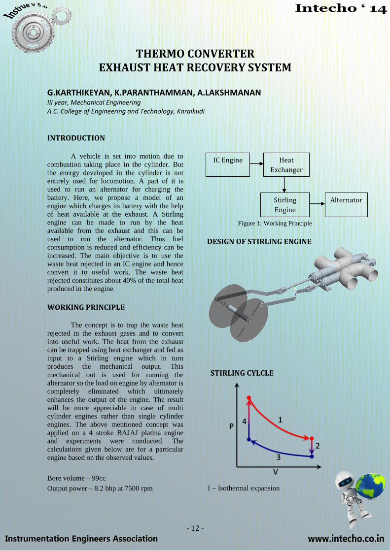
Figure 1: Working Principle
DESIGN OF STIRLING ENGINE
STIRLING CYLCLE
1 – Isothermal expansion
IC Engine Heat
Exchanger
Stirling
Engine
Alternator

- 13 -
2 – Isochoric heat removal
3 – Isothermal compression
4 – Isochoric heat addition
THEORITICAL CALCULATIONS
The mass of exhaust gas leaving the
combustion chamber can be calculated using
the displacement volume.
The displacement volume = 100cc (approx.)
Let us consider the density (D) of exhaust gas
is equal to atmospheric air.
D=1kg/m3
Let us consider the engine is running at a
normal speed of 3000 rpm.
N= 3000/60 rps=50rps
Since it is 4stroke engine,
No of exhaust strokes in 1 sec = 25
Volume of exhaust discharged/sec = 25*100
=2500 cc/sec
= 0.025 m3/sec
Mass =D*V= 1kg/m3*0.025 m
3/ sec
So mass flow rate through the exhaust
manifold is 0.025m3/sec.
HEAT REJECTED FROM EXHAUST
Temperature of the exhaust gases
rated speed (7500 rpm) 200.C (approx.) Let us
assume that at nominal speed of 3500rpm the
temperature of the exhaust gases might be up
to 120.C (approx.) as the speed of the engine
increases the heat lost in exhaust increases.
Theoretically speaking the heat rejected
= cp*difference in temperature.
Mean specific heat of exhaust heat = 1.0
kJ/KgK
Exhaust temp = 120.C
Atmospheric temp = 30.C
Mass = 0.025 m3/
sec
Heat rejected = Cpexhaust (120-30)
Heat rejected = 90kJ/Kg of exhaust gas
Power produced from this heat = 2.25 kW
OVERALL EFFICIENCY
Overall efficiency = (0.34/2.25)*100
= 15.11% (approx.)
Temperature of the exhaust gases rated speed
(7500 rpm) 200.C (approx.)
Heat rejected = Cpexhaust * (200-30)
Mean specific heat of exhaust heat= 1.0
kJ/KgK
Heat rejected = 170 kJ/Kg of exhaust gas
(approx.)
Heat given to the heat exchanger = heat
rejected in exhaust
Efficiency of the heat exchanger = 85%
(approx.)
So the heat input to the Stirling engine is =
heat transferred from heat exchanger = 170
*(85/100)
Heat input to Stirling engine = 144.5 kJ/kg of
exhaust gas
Efficiency of Stirling engine = 40% (approx.)
So the workout produced =57.8 watts
POWER REQUIRED BY AN ALTERNATOR (including loses)
Small engines require 1.75hp to run
the alternator for charging the battery.
= 1305.5 W
= 1.3 kW
So a Stirling engine should be designed for the
maximum capacity of 5kW and an average
capacity of 3kW to ensure the proper charging
of battery.
INCREASE IN EFFICIENCY
Output of the engine without
THERMO CONVERTOR = 8.2 bhp
at 7500 rpm
Output of the engine with THERMO
CONVERTOR
= (8.2*746) +57.8
=6175 watts at 7500 rpm
=8.2775 bhp at 7500 rpm
increase in bhp = 8.2775-8.2000
=0.0775 bhp
increase in power = 0.0775*746
= 57.18 watt
efficiency of the engine without
thermo convertor = 14.2260%
efficiency of the engine with thermo
convertor = 14.3605%
increase in efficiency due to usage of
thermo convertor
- 14 -
= 14.3605-14.226
= 0.13%
TESTING AND CONCLUSION
The engine was tested for the exhaust
temperature at rated speed (3000 rpm). The
maximum temperature of exhaust gas is
determined. The heat exchanger is tested at its
maximum temperature limits. The Stirling
engine is also tested for its maximum
temperature limits.
From the above tests the actual
efficiency are determined and compared with
the theoretical values. From the above
calculations we conclude that the efficiency of
an IC engine increases when THERMO
CONVERTOR is used. The increase in value
is appreciable in case of multi-cylinder
engines.
DID YOU KNOW?
If you scuffed your feet long
enough without touching
anything, you would build up so
many electrons that your finger
would explode! But this is
nothing to worry about unless
you have carpeting! The
electrons travel through your
bloodstream and collect in your
finger, where they form a spark
that leaps to your friend's filling,
then travels down to his feet and
back into the carpet, thus
completing the circuit!
TRAINING HIGHLIGHTS
Excellent placements
Unlimited practical
Individual focus
Hands-on practical training
Real time projects
Industrial faculties
Onsite Industrial training
Control panel wiring
Fully equipped advanced lab
Case studies for various processes
Free accommodation
- 15 -
WAKE REDUCTION USING VORTEX GENERATORS AS PASSIVE FLOW DEVICES
MUTHU GANESH M.S III year, Automobile Engineering, BIT campus, Anna University, Trichy
INTRODUCTION
The constant need for better fuel
economy, greater vehicle performance, and
reduction in wind noise level and improved
road holding and stability for a vehicle on the
move has prompted vehicle manufacturers to
investigate the nature of air resistance or drag
for different body shapes under various
operating conditions. Aerodynamic drag is
usually insignificant at low vehicle speed but
the magnitude of air resistance becomes
considerable with rising speed. A vehicle with
high drag resistance tends only marginally to
hinder its acceleration but it does inhibit its
maximum speed and increase the fuel
consumption with increasing speed.
CFD SIMULATION ON THE WAKE OF A CAR MODEL
Computational fluid dynamics, usually
abbreviated as CFD, is a branch of fluid
mechanics that uses numerical methods and
algorithms to solve and analyze problems that
involve fluid flows. Computers are used to
perform the calculations required to simulate
the interaction of fluid with surfaces defined
by boundary conditions.
WAKE REDUCTION USING VORTEX GENERATORS
Flow control methods
The ability to manipulate a flow field
to improve efficiency or performance is of
immense technological importance. The
potential benefits of flow control include
improved performance and manoeuvrability,
affordability, increased range and payload, and
environmental compliance. The intent of flow
control may be to delay/advance transition, to
suppress/enhance turbulence, or to prevent or
promote separation. The resulting benefits
include drag reduction, lift enhancement,
mixing augmentation, heat transfer
enhancement, and flow-induced noise
suppression.
Classification of Flow control methods
Classification of flow control methods
is based on energy expenditure and the control
loop involved. Flow control involves passive
or active devices that have a beneficial change
on the flow field. A considerable amount of
research has been performed using passive
methods of flow control, which modify a flow
without external energy expenditure.
In cases in which the control must
interact with a specific set of turbulent
fluctuations already present in the flow, such
as random coherent structures, the
effectiveness of an open-loop system is
reduced.
Passive Device flow control method
Passive techniques include geometric
shaping to manipulate the pressure gradient,
the use of fixed mechanical vortex generators
for separation control, and placement of
longitudinal grooves or riblets on a surface to
reduce drag.
Vortex Generator as Passive control device
A vortex generator is an aerodynamic
surface, consisting of a small vane or bump
that creates a vortex. Vortex generators are
likely to be found on the external surfaces of
- 16 -
vehicles where flow separation is a potential
problem because vortex generators delay flow
separation. They are typically rectangular or
triangular, about 80% as tall as the boundary
layer. Since the flow angles and the air foil
thickness are better behaved on the outer part,
VGs are generally not used here since they
besides from suppressing separation, also yield
an increased drag. These devices are
sometimes a part of the blade design, but are
also used to change unexpected flow
separation on already manufactured clean
blades. Vortex Generators have many
geometrical parameters like general shape,
height, length and angle to the main flow
direction. Further, it is necessary to specify the
chord wise position and span wise spacing on
the blade.
Wake reduction by Passive device (Vortex Generators)
A vortex generator creates a tip vortex
which draws energetic, rapidly-moving air
from outside the slow-moving boundary layer
into contact with the aircraft skin. The
boundary layer normally thickens as it moves
along the aircraft surface, reducing the
effectiveness of trailing-edge control surfaces;
vortex generators can be used to remedy this
problem, among others, by re-energizing the
boundary layer. Vortex generators delay flow
separation and aerodynamic stalling; they
improve the effectiveness of control surfaces
and, for swept-wing transonic designs; they
alleviate potential shock-stall problems.
Vortex generators are series of small winglets
that are glued on to the blade shortly upstream
of the separated region. By creating
longitudinal vortices, they mix high
momentum free stream air into the bottom of
the boundary layer, thus delaying separation.
By delaying the boundary layer separation, the
wake that is present behind the vehicle gets
reduced and thus the fuel efficiency is
increased.
CONCLUSION
The passive flow control method is
chosen to minimize the wake region behind
the vehicle. Vortex generator is chosen as
passive device which creates vortices, where
the laminar flow gets converted into turbulent
flow and so the boundary layer separation gets
delayed. Due to this the wake region behind
the vehicle minimized i.e., the low pressure
region behind the vehicle gets reduced.
TRIVIA
The word Engineer comes from the Latin word meaning ‘cleverness’.
The temperature in Fahrenheit can be determined by counting the
number of cricket chirps in 14 seconds and adding 40.
The effect of Relativity made astronaut Sergei Avdeyev a fraction of a
second younger upon his return to Earth after 747 days in space.
People say "Bless you" when you sneeze because when you sneeze,
your heart stops for a millisecond
The cigarette lighter was invented before the match
Like fingerprints, everyone's tongue print is different
Wearing headphones for just an hour will increase the bacteria in
your ear by 700 times.
- 17 -
EEG BASED ACQUISITION DEVICE
FOR A BRAIN ACTUATED BIONIC ARM
DINESH KUMAR. S, NITHYADHARSHNI.S III year, Electronics and Instrumentation, Madras Institute of Technology.
INTRODUCTION
Robots have become important in a
wide range of applications, one of which is a
robotic arm. The recent emergence of
successfully performing Brain-Computer
Interfaces (BCI), has given a new hope for the
disabled and elderly population for
improvements in quality of life. The present
BCI creates a very strong symbiotic
relationship between humans and machines.
HOW DOES A BRAIN GENERATE A SIGNAL?
Neurons communicate through an
electro-chemical process. When a signal
reaches a synapse, it triggers the release of
neuro-transmitters, which are small molecules
that diffuse in inter cellular space, and this
activates the receptors on other synapses. In
turn, the activated receptor generates electrical
signals of variable intensities. The signal
coming from every synapse of a neuron
passively converges to the base of its axon and
then they are summed up .Therefore, the
neurons use electricity to communicate with
each other .Thus, millions of electrons sending
signals at the same time produce an enormous
amount of electrical activity in the brain,
commonly known as the brain wave pattern
because of its cyclic wave nature
PRINCIPLE OF BCI
A BCI has four components- a signal
capture system, a signal processing system, a
pattern recognition system, a device control
system. The signal capture system makes use
of scalp electrodes, together with a sticky gel,
to obtain signal which passes through a unity
gain amplifier to boost its level for process.
Using Fast Fourier transform algorithms, it is
converted into a discrete signal. A digital
signal processing software is used for proper
sequence generation, after which its output is
fed to a pattern recognition system to select the
proper system. These brain waves are
generated due to the differences in electrical
properties carried by ions on membrane of
each neutron.
PLACEMENT OF ELECTRODES IN THE SIGNAL CAPTURING SYSTEM
For placement of electrodes, the 10-20
system is used, which describes the exact
location of the scalp electrodes. EEG
technique uses an electrode cap that is placed
on the user‘s scalp for the acquisition of the
EEG signal, which relates the scalp potential
differences to various complex actions.
Classification of the EEG signal has been
made into several bands like alpha, beta, delta,
theta and mu suppression, each corresponding
to various states of 'being' like relaxing,
ranging over 8-14 Hz; concentrating, ranging
over 13-30 Hz; deep sleep, from 0-4 Hz;
meditating from 4-8 Hz; moving your hands or
legs or just by imagining these motor actions
respectively.
DATA ACQUISITION
The article presents how to control a
cursor in 2D using EEG based brain computer
interface. The movements of the cursor on the
computer screen are controlled based on the
EEG scalp potentials. The EEG signal is
mapped from the user head to the 2D cursor
control. The horizontal motion is based on the
mu beta rhythm and vertical motion is based
on P300 potential respectively. The user can
move the cursor horizontally to the right or left
just by imagining his right or left hand motion
and he can move the cursor vertically upwards
or downwards by focusing on the UP button or
DOWN button on the monitor respectively.
- 18 -
P300-BASED BCI PARADIGM
The paradigm comprises four steering
commands, θUA, encoded by the following
symbols: FORWARD, RIGHT, DOWN,
LEFT and STOP. These symbols flash
randomly with an inter-symbol interval (ISI)
of 75 ms, and a flash duration of 100 ms, i.e.,
the Stimuli Onset Asynchrony (SOA) is 175
ms. Because of the low SNR of P300 ERPs,
several P300 responses have to be collected
before machine learning algorithms can
identify the mentally selected symbol.
Therefore, the overall time needed for symbol
detection (TT—trial time) depends on the
number of event repetitions (Nrep), yielding
TT = Nrep × Ns × SOA + 1
Where Ns is the number of symbols (Ns = 4),
and the value 1 is the time required to record
the EEG associated with the last event of a
trial (e.g., for a user requiring 3 repetitions, TT
= 4 × 0.175 × 3 + 1 = 3.1 s). The number of
repetitions is adjusted for each participant
according to his/her offline accuracy, obtained
during the BCI calibration.
EEG SIGNAL ACQUISITION
This stage targets the careful
extraction of the EEG signal from the user
scalp. It is made up of different components
such as instrumentation amplifier, operational
amplifier, high pass, low pass and notch filters.
The EEG signal extracted by the
instrumentation amplifier is passed through the
high pass, low pass and notch filters after
amplification by Op-Amp. Integration of a
notch filter will filter out undesirable power
line signal. The high pass filter, removes the
noise in the signal and low pass filter extracts
the signal frequencies of interest.
SIGNAL TRANSMISSION
This stage focuses on the transmission
of the acquired EEG signal to a PC. EEG
signal is digitized by 12-bit A/D converted and
then transmitted to a PC through Opto-coupler
for electrical isolation.
SIGNAL PROCESSING
In this stage, the EEG signal gets
processed in the MATLAB and is used for
controlling a 2D cursor on the GUI. The
simulation of the EEG amplifier can be done
using Multisim Simulation tool. The EEG
amplifier consists of an instrumentation
amplifier, operational amplifier and a voltage
follower with a virtual ground set up. Two
First Order high pass filters are integrated; one
each after instrumentation amplifier and
operational amplifier. A first order low pass
filter is integrated along with the operational
amplifier. A high pass filter is coupled in
between pre and post amplification stages and
another is coupled after post amplification
stage. Each of these high pass filters prevents
the low frequency noise being carried to the
later stage. A low pass filter is integrated
along with the OP-AMP to extract the
frequencies of interest.
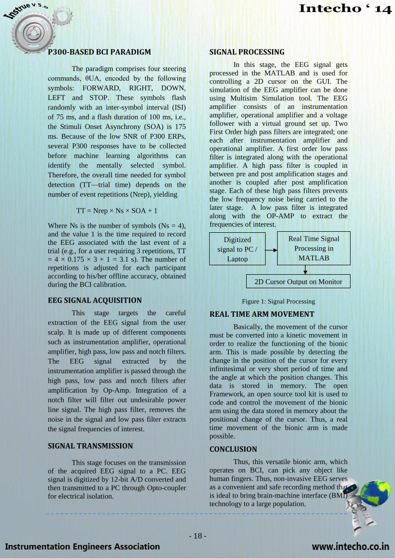
Figure 1: Signal Processing
REAL TIME ARM MOVEMENT
Basically, the movement of the cursor
must be converted into a kinetic movement in
order to realize the functioning of the bionic
arm. This is made possible by detecting the
change in the position of the cursor for every
infinitesimal or very short period of time and
the angle at which the position changes. This
data is stored in memory. The open
Framework, an open source tool kit is used to
code and control the movement of the bionic
arm using the data stored in memory about the
positional change of the cursor. Thus, a real
time movement of the bionic arm is made
possible.
CONCLUSION
Thus, this versatile bionic arm, which
operates on BCI, can pick any object like
human fingers. Thus, non-invasive EEG serves
as a convenient and safe recording method that
is ideal to bring brain-machine interface (BMI)
technology to a large population.
Real Time Signal
Processing in
MATLAB
Digitized
signal to PC /
Laptop 2D Cursor
Output on
Monitor 2D Cursor Output on Monitor
- 19 -
MUFFLER AND RESONATOR OPTIMIZATION
A. FELIX SAHAYARAJ M.E., Manufacturing Engineering, M.I.E.T., Trichy
INTRODUCTION
The key objective in designing a
vehicle is ―Cleaner, Quieter and Safer driving
of the vehicle‖. The other important areas of
focus include emission regulation, NVH
(Noise Vibration Harshness) regulation and
durability of the vehicle. The main sources of
noise in a vehicle are the exhaust noise and the
noise produced due to friction of various parts
of the engine. In an automotive engine,
pressure waves are generated when the exhaust
valve repeatedly opens and lets high-pressure
gas into the exhaust system. These pressure
pulses are the sound we hear. As the engine
rpm increases, so do the pressure fluctuations
and therefore the sound emitted is of a higher
frequency. To reduce this noise, various kinds
of muffler and resonator combinations are
used. Muffler is a sound attenuating device,
which also has a role in engine performance.
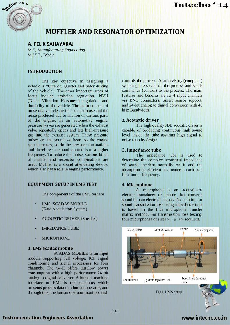
EQUIPMENT SETUP IN LMS TEST
The components of the LMS test are
• LMS SCADAS MOBILE
(Data Acquisition System)
• ACOUSTIC DRIVER (Speaker)
• IMPEDANCE TUBE
• MICROPHONE
1. LMS Scadas mobile SCADAS MOBILE is an input
module supporting full voltage, ICP signal
conditioning and signal processing for four
channels. The v4-II offers ultralow power
consumption with a high performance 24 bit
analog to digital converter. A human–machine
interface or HMI is the apparatus which
presents process data to a human operator, and
through this, the human operator monitors and
controls the process. A supervisory (computer)
system gathers data on the process and sends
commands (control) to the process. The main
features and benefits are its 4 input channels
via BNC connectors, Smart sensor support,
and 24-bit analog to digital conversion with 46
kHz Bandwidth.
2. Acoustic driver
The high quality JBL acoustic driver is
capable of producing continuous high sound
level inside the tube assuring high signal to
noise ratio by design.
3. Impedance tube The impedance tube is used to
determine the complex acoustical impedance
of sound incident normally on it and the
absorption co-efficient of a material each as a
function of frequency.
4. Microphone A microphone is an acoustic-to-
electric transducer or sensor that converts
sound into an electrical signal. The solution for
sound transmission loss using impedance tube
is based on the four microphone transfer
matrix method. For transmission loss testing,
four microphones of sizes ¼, ½‖ are required.
Fig1. LMS setup
- 20 -
DESIGN METHODOLOGY Traditional design method
Cut and try method
Acoustic prediction method
Time domain prediction
Frequency domain prediction
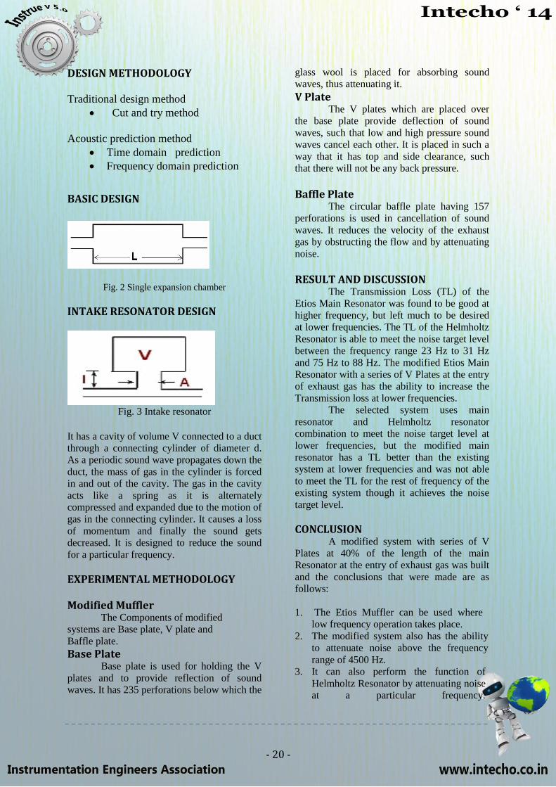
BASIC DESIGN
Fig. 2 Single expansion chamber
INTAKE RESONATOR DESIGN
Fig. 3 Intake resonator
It has a cavity of volume V connected to a duct
through a connecting cylinder of diameter d.
As a periodic sound wave propagates down the
duct, the mass of gas in the cylinder is forced
in and out of the cavity. The gas in the cavity
acts like a spring as it is alternately
compressed and expanded due to the motion of
gas in the connecting cylinder. It causes a loss
of momentum and finally the sound gets
decreased. It is designed to reduce the sound
for a particular frequency.
EXPERIMENTAL METHODOLOGY
Modified Muffler The Components of modified
systems are Base plate, V plate and
Baffle plate.
Base Plate Base plate is used for holding the V
plates and to provide reflection of sound
waves. It has 235 perforations below which the
glass wool is placed for absorbing sound
waves, thus attenuating it.
V Plate The V plates which are placed over
the base plate provide deflection of sound
waves, such that low and high pressure sound
waves cancel each other. It is placed in such a
way that it has top and side clearance, such
that there will not be any back pressure.
Baffle Plate The circular baffle plate having 157
perforations is used in cancellation of sound
waves. It reduces the velocity of the exhaust
gas by obstructing the flow and by attenuating
noise.
RESULT AND DISCUSSION The Transmission Loss (TL) of the
Etios Main Resonator was found to be good at
higher frequency, but left much to be desired
at lower frequencies. The TL of the Helmholtz
Resonator is able to meet the noise target level
between the frequency range 23 Hz to 31 Hz
and 75 Hz to 88 Hz. The modified Etios Main
Resonator with a series of V Plates at the entry
of exhaust gas has the ability to increase the
Transmission loss at lower frequencies.
The selected system uses main
resonator and Helmholtz resonator
combination to meet the noise target level at
lower frequencies, but the modified main
resonator has a TL better than the existing
system at lower frequencies and was not able
to meet the TL for the rest of frequency of the
existing system though it achieves the noise
target level.
CONCLUSION A modified system with series of V
Plates at 40% of the length of the main
Resonator at the entry of exhaust gas was built
and the conclusions that were made are as
follows:
1. The Etios Muffler can be used where
low frequency operation takes place.
2. The modified system also has the ability
to attenuate noise above the frequency
range of 4500 Hz.
3. It can also perform the function of
Helmholtz Resonator by attenuating noise
at a particular frequency.
- 21 -
AUTOMATED BLOOD DELIVERY SYSTEM
NITIN K III Year, Computer Science and Engineering, Madras Institute of Technology
INTRODUCTION
Medical emergencies in hospitals are taken care of today with sophisticated technology and intelligent research. However, the delay in transportation of blood packets or drugs from the inventory unit to the operating room is a serious concern to all health centers. This delay could prove fatal if not done efficiently. Recent technology development provides a solution to this problem but is not feasible in developing countries. The use of intelligent agent based delivery is the heart of this proposal. A MONORAIL AND ROBOT MECHANISM
To avoid the complexity of transporting
articles of non-emergency, this specifically
designed robot can serve to transfer blood and
drugs from the inventory unit to the operating
room only. Using an efficient GPS tracking and
bar-coding technique this model could become a
cheap and feasible solution to problems faced by
most hospitals all over the world.
DESIGN AND SPECIFICATIONS
The design comprises of a monorail track, a few centimeters above the floor which runs only from the inventory unit to the operating room or an intensive care room. The monorail preferably runs along one side of every available path. A mini robot with inbuilt sensors for path detection, tracking and with a wireless data transceiver is mounted on the monorail stand. The robot is provided with a container on the above with a capacity of necessary size. The container is provided with a safety latch to be protected from external environment. The robot is powered by a high speed electrical motor. A timer unit is inbuilt to calculate time delay.
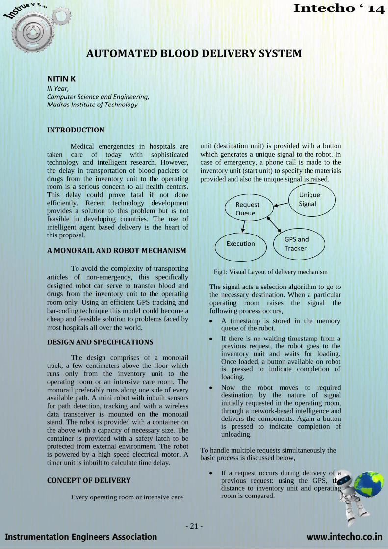
CONCEPT OF DELIVERY
Every operating room or intensive care
unit (destination unit) is provided with a button
which generates a unique signal to the robot. In
case of emergency, a phone call is made to the
inventory unit (start unit) to specify the materials
provided and also the unique signal is raised.
Fig1: Visual Layout of delivery mechanism
The signal acts a selection algorithm to go to the necessary destination. When a particular operating room raises the signal the following process occurs,
A timestamp is stored in the memory
queue of the robot.
If there is no waiting timestamp from a previous request, the robot goes to the inventory unit and waits for loading. Once loaded, a button available on robot is pressed to indicate completion of loading.
Now the robot moves to required
destination by the nature of signal initially requested in the operating room, through a network-based intelligence and delivers the components. Again a button is pressed to indicate completion of unloading.
To handle multiple requests simultaneously the basic process is discussed below,
If a request occurs during delivery of a previous request: using the GPS, the distance to inventory unit and operating room is compared.
Unique Signal Request
Queue
GPS and Tracker
Execution

- 22 -
If operating room is closer, the previous
request is completed first and then the present request is attended to.
If the inventory unit is closer, the robot
goes back to start position to load the latest request and delivers both the packages based on the timestamp queue recorded i.e. earlier timestamp request is delivered first.
In a multi-request (say 2-request process) handling mechanism, the commonly used methods are, void isStartUnit() {
error() if(location=start unit)
return else
{ Go to start unit //delay
return(isStartUnit ()) }
}
void checkButtonPress() {
error () if(button press?) return else {
//delay return(buttonPress ())
} } void error() {
if (waiting time of request 1 > max time allowed || waiting time of request 2 if any > max time allowed ) {
//Report error of request exit ()
} }
int checkRequest() {
return(checkPossibility()) }
int checkPossibility() {
if (destination distance > distance to start
unit || waiting time > max waiting time)
return 0
else return 1
}
reload() {
isStartUnit () checkButtonPress ()
}
The overall Pseudo code which handles a 2-
request process is,
1. Get timestamp if signal arises
While (timestamp queue! =NULL) {
if (queue update at any instant through interrupt && checkPossilbity() ) {
//Continue previously //ongoing process
} else {
reload () error () checkButtonPress () error () checkButtonPress () //Go to start unit //Repeat step 1
} isStartUnit () checkButtonPress() //Move along preset path and go //to destination unit error() checkButtonPress () //Return to start unit
}
2. Repeat step 1 3. End
CONCLUSION
A cost-efficient delivery system is the
need of the hour in most developing countries.
Such effective mechanisms help in speedy
delivery of immediate resources thereby
immensely reducing fatal losses due to delay.

- 23 -
TECHNICAL CROSSWORD
Across
4. An important measure especially in communication.
9. An input which is generally a disturbance.
10. The most widespread example of galvanic isolation.
11. It is actually a resistor, a transfer resistor!
15. The process of varying one or more properties of a periodic waveform.
17. 3-15psi to 4-20ma.
18. The basis of automation.
19. Torque proportional to square of current in this instrument.
20. 1,650,763.73 wavelengths of light from a specified transition in Krypton-86.
21. A signal to the processor emitted by hardware or software indicating an event that needs
immediate attention.
Down
1. A type of motor for moving or controlling a mechanism or system.
2. A unit of viscosity.
3. I sometimes do this to get the slope.
5. This is exactly what you would need for constant voltage.
6. The phenomenon in which the value of a physical property lags behind changes in the effect
causing it.
7. A typical control algorithm.
8. A very important parameter of a controller.
12. The electrical equivalent of spring.
13. A reaction to something.
14. What do you do when there is a noise in your signal?
16. Also called as half power point.
- 24 -
EQUALIZED POWER REGULATION AMONG
HOUSEHOLDS USING REAL TIME CLOCK BASED
INTELLIGENT METERING SYSTEM
B. RAJAPANDIAN SRIKRISHNA.C, S.B. SHRIRAMAsst. Professor, U.G., Dept.,of Electronics and Instrumentation, Dept., of Electronics and Instrumentation, Sri Sairam Engineering College, Chennai. Sri Sairam Engineering College, Chennai.
INTRODUCTION
One of the major concerns for every
one is the fast depleting natural resources. High
power needs at cities which has less power cuts
than other areas. For the sake of our power
starved industries, to save our economy, we
must evenly distribute power rather following
the present system.
EXISTING SYSTEMS
Presently we have the power from the
substations and master metering system. The
methods we have been using now are
Electronic energy meter with remote
monitoring and prepaid billing system,
measuring energy meter of three-phase
electricity, planning optimal intelligent
metering for distribution system monitoring
and control. They have the following
drawbacks:
a) Unequal power distribution to host
b) Mismatching of power loads and usage of
power.
c) Current tripping and thefts.
d) Master metering system-dividing unequal
power to the rural and urban industries.
e) Voltage and current fluctuation due to higher
load values.
NEED FOR REGULATION
Once there was a time where the
power generated is sub utilized by
maintenance, and also it was equally
distributed without the need for the regulation
criteria. But now due to increase in
consumption and load changes, the regulations
were done only at substation level and not to
host.
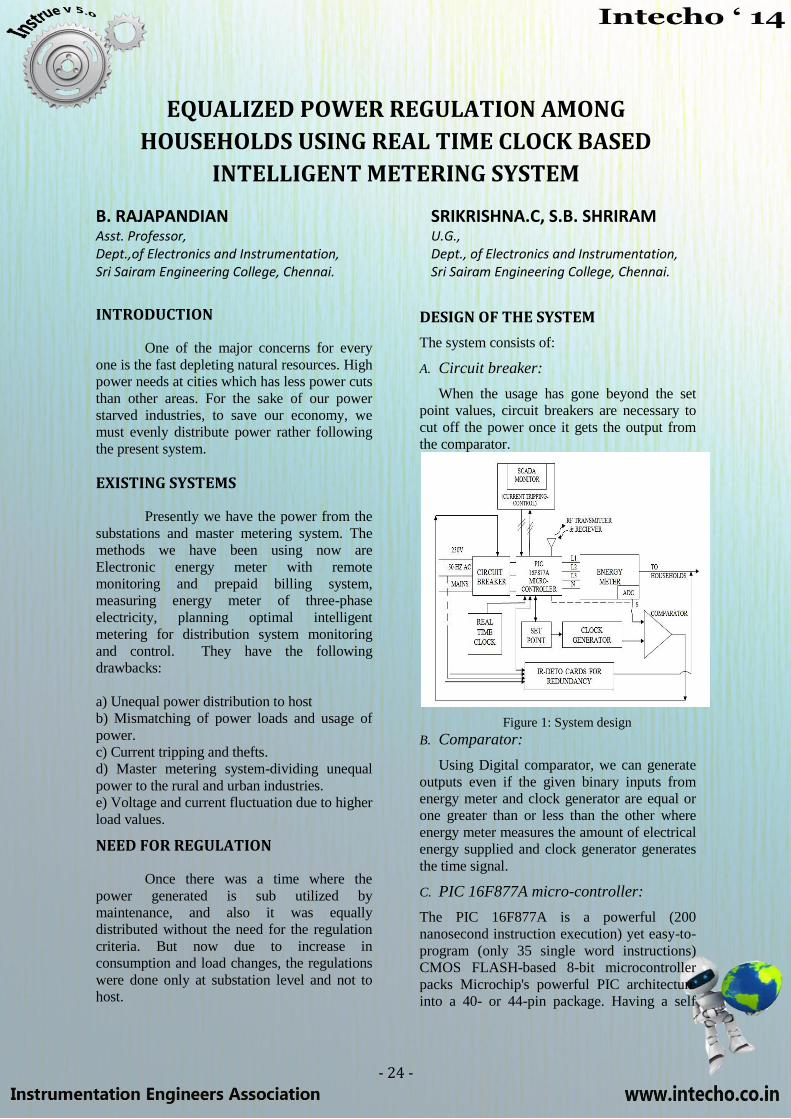
DESIGN OF THE SYSTEM
The system consists of:
A. Circuit breaker:
When the usage has gone beyond the set
point values, circuit breakers are necessary to
cut off the power once it gets the output from
the comparator.
Figure 1: System design
B. Comparator:
Using Digital comparator, we can generate
outputs even if the given binary inputs from
energy meter and clock generator are equal or
one greater than or less than the other where
energy meter measures the amount of electrical
energy supplied and clock generator generates
the time signal.
C. PIC 16F877A micro-controller:
The PIC 16F877A is a powerful (200
nanosecond instruction execution) yet easy-to-
program (only 35 single word instructions)
CMOS FLASH-based 8-bit microcontroller
packs Microchip's powerful PIC architecture
into a 40- or 44-pin package. Having a self
- 25 -
programming feature it uses 8 channels of 10-
bit (A/D) converter for input output and a
Universal Asynchronous Receiver Transmitter
(USART) for RF data transmission &
reception.
D. Scada Monitor:
Supervisory control through data
acquisition (SCADA) which is more secure
and effective, is the automated way of
detecting the mal usage of the energy.
E. Ir-deto cards for redundancy:
Ir-deto cards can be used as redundancy
system in cases of power shortage during
emergencies.
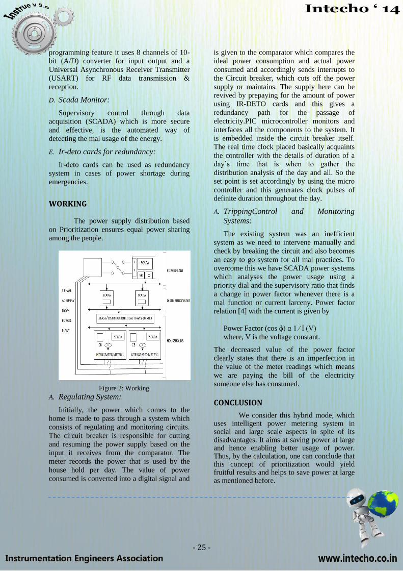
WORKING
The power supply distribution based
on Prioritization ensures equal power sharing
among the people.
Figure 2: Working
A. Regulating System:
Initially, the power which comes to the
home is made to pass through a system which
consists of regulating and monitoring circuits.
The circuit breaker is responsible for cutting
and resuming the power supply based on the
input it receives from the comparator. The
meter records the power that is used by the
house hold per day. The value of power
consumed is converted into a digital signal and
is given to the comparator which compares the
ideal power consumption and actual power
consumed and accordingly sends interrupts to
the Circuit breaker, which cuts off the power
supply or maintains. The supply here can be
revived by prepaying for the amount of power
using IR-DETO cards and this gives a
redundancy path for the passage of
electricity.PIC microcontroller monitors and
interfaces all the components to the system. It
is embedded inside the circuit breaker itself.
The real time clock placed basically acquaints
the controller with the details of duration of a
day‘s time that is when to gather the
distribution analysis of the day and all. So the
set point is set accordingly by using the micro
controller and this generates clock pulses of
definite duration throughout the day.
A. TrippingControl and Monitoring
Systems:
The existing system was an inefficient
system as we need to intervene manually and
check by breaking the circuit and also becomes
an easy to go system for all mal practices. To
overcome this we have SCADA power systems
which analyses the power usage using a
priority dial and the supervisory ratio that finds
a change in power factor whenever there is a
mal function or current larceny. Power factor
relation [4] with the current is given by
Power Factor (cos ɸ) α 1 ∕ I (V)
where, V is the voltage constant.
The decreased value of the power factor
clearly states that there is an imperfection in
the value of the meter readings which means
we are paying the bill of the electricity
someone else has consumed.
CONCLUSION
We consider this hybrid mode, which uses intelligent power metering system in social and large scale aspects in spite of its disadvantages. It aims at saving power at large and hence enabling better usage of power. Thus, by the calculation, one can conclude that this concept of prioritization would yield fruitful results and helps to save power at large as mentioned before.
- 26 -
BLOOM BOX
S. SHIV SHANKAR II year, Electronics and Instrumentation. Madras Institute of Technology
INTRODUCTION
A fuel cell is a voltaic cell which
converts the chemical energy of fuel directly
into electricity without combustion. When a
large number of fuel cells are connected in
series, it forms a battery. The recent and the
most significant development in the field of fuel cell is ―Bloom Box‖.
DEVELOPMENT OF BLOOM BOX
Dr. K.R.Sridhar, an engineering
graduate from Trichy, developed Bloom Box,
which uses natural gas as fuel to develop
electricity. When he was working in NASA,
he did a research to obtain oxygen by
supplying electricity. This research was to
check whether favourable conditions are there
in Mars for living. But, unfortunately his
research work was scrapped by NASA. He
then reversed his idea. When oxygen was
supplied along with fuel, he obtained
electricity! The basic formula is:
CH₄ + 2O₂→Electricity+ CO₂ +2H₂O+Heat
THE BLOOM BOX
For the Bloom Box, external
power source is not needed. Sand is baked till
it turns into ceramic and it is cut into little
squares. Then, the ceramic substance is
painted on either side with special green and black inks to get green and black layers.
The anode is made up of Green Nickel
Oxide and the cathode is made up of Black
Lanthanum Strontium Magnetite. The above
combinations form disks which are stacked
together separated by cheap metal alloys. It
has a wireless router to transmit power wirelessly.
It has the following specifications
1 fuel cell ---- 25W (1 disk)
1 stack --------1KW (40 disks)
1 module------25KW (25 stacks)
1 Server--------100KW (4 modules)
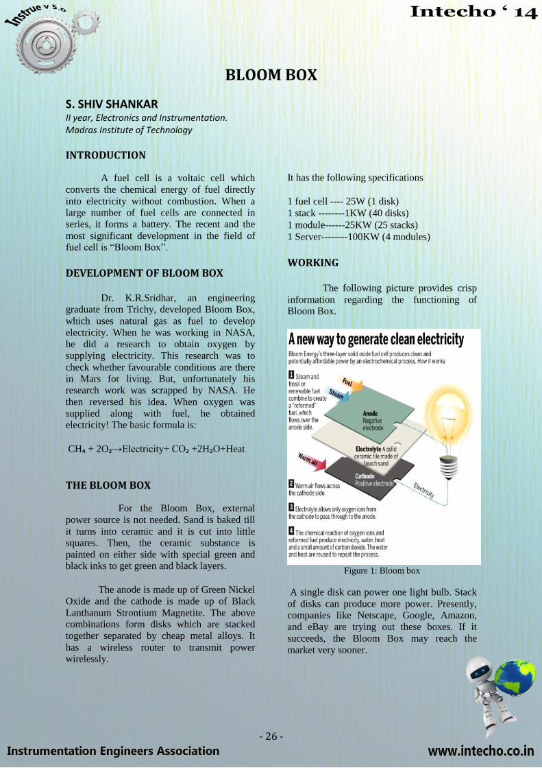
WORKING The following picture provides crisp
information regarding the functioning of Bloom Box.
Figure 1: Bloom box
A single disk can power one light bulb. Stack
of disks can produce more power. Presently,
companies like Netscape, Google, Amazon,
and eBay are trying out these boxes. If it
succeeds, the Bloom Box may reach the
market very sooner.

- 27 -
ADVANTAGES
• Main objective is to replace the grid
and bloom box is cleaner and cheaper than grid.
• Wireless power transfer: Highly
efficient since in conventional
methods, 40% of electricity is lost during transmission.
• It acts as a continuous source of
energy. The fuel is continuously supplied to produce power.
• It can withstand temperatures up to 9800 C.
• It can be used in remote areas where
the construction of electric poles and
transmission of electricity is very difficult.
CONCLUSION
The newest offshoot in the field of
electricity is wireless power transmission and
Bloom Box is going to become a ―trendsetter‖
in near future. Wire usage, cost, and
transmission losses are completely avoided by
this technology. As it is rightly said, ―Every
invention augments the power of man and the
well-being of mankind‖ -no doubt, the world is
pacing towards a greener environment.
FUN FACTS
Golf balls have dimples because they help reduce drag; this allows the ball to fly further than a smooth ball would.
The tallest wind turbine in the world has rotor tips that reach over 200 meters (656 feet) above the ground.
A car travelling at 80km/h uses half its fuel to overcome wind
resistance.
WHAT WE DO
Electro mechanical turnkey Projects
Control Automation system integration E & I turnkey projects
OEM Solutions
Information solutions and manufacturing intelligence solutions
Customer support
Technical resource deployment
Products and Standard Solutions
- 28 -
STRATELLITES
KESAVAN.G, LOGANATHAN.N.N III YEAR, Electronics and Communication, Madras Institute of Technology
INTRODUCTION
A ―stratellite‖ is a high-altitude airship
(HAA) 25 times larger than the Goodyear
blimp employed much like a satellite for
remote sensing, navigation, and
communications. Instead of being stationed on
orbit, stratellites are positioned in the
stratosphere approximately 13 miles above the
Earth. From this height, stratellites can service
a 300,000-square-mile-area. The North
American Aerospace Defence Command
(NORAD) projects that eleven such airships
could provide radar coverage of the entire
maritime and southern borders of the United
States.
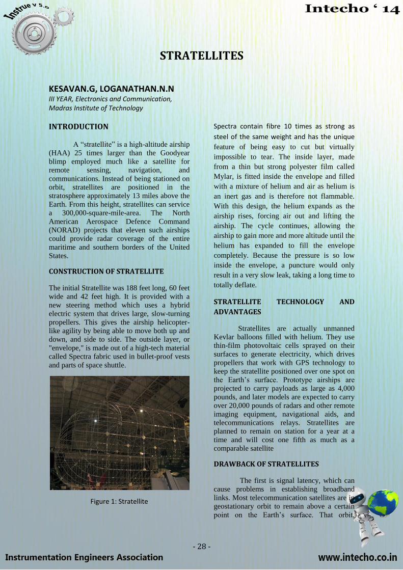
CONSTRUCTION OF STRATELLITE
The initial Stratellite was 188 feet long, 60 feet
wide and 42 feet high. It is provided with a
new steering method which uses a hybrid
electric system that drives large, slow-turning
propellers. This gives the airship helicopter-
like agility by being able to move both up and
down, and side to side. The outside layer, or
"envelope," is made out of a high-tech material
called Spectra fabric used in bullet-proof vests
and parts of space shuttle.
Figure 1: Stratellite
Spectra contain fibre 10 times as strong as
steel of the same weight and has the unique
feature of being easy to cut but virtually
impossible to tear. The inside layer, made
from a thin but strong polyester film called
Mylar, is fitted inside the envelope and filled
with a mixture of helium and air as helium is
an inert gas and is therefore not flammable.
With this design, the helium expands as the
airship rises, forcing air out and lifting the
airship. The cycle continues, allowing the
airship to gain more and more altitude until the
helium has expanded to fill the envelope
completely. Because the pressure is so low
inside the envelope, a puncture would only
result in a very slow leak, taking a long time to
totally deflate.
STRATELLITE TECHNOLOGY AND
ADVANTAGES
Stratellites are actually unmanned
Kevlar balloons filled with helium. They use
thin-film photovoltaic cells sprayed on their
surfaces to generate electricity, which drives
propellers that work with GPS technology to
keep the stratellite positioned over one spot on
the Earth‘s surface. Prototype airships are
projected to carry payloads as large as 4,000
pounds, and later models are expected to carry
over 20,000 pounds of radars and other remote
imaging equipment, navigational aids, and
telecommunications relays. Stratellites are
planned to remain on station for a year at a
time and will cost one fifth as much as a
comparable satellite
DRAWBACK OF STRATELLITES
The first is signal latency, which can
cause problems in establishing broadband
links. Most telecommunication satellites are in
geostationary orbit to remain above a certain
point on the Earth‘s surface. That orbit,
- 29 -
however, is 22,240 miles above the Earth
which means that a signal going up to the
satellite and back to the Earth travels nearly
45,000 miles, which equates to about a quarter
of a second delay. Even users of satellite voice
links notice the delay.
The second drawback is that satellites
are in space, requiring expensive space
launches, an additional level of regulation by
national space authorities and an orbital
allotments by the International
Telecommunication Union(ITU).Stratellites
remain in national airspace and are therefore
not subject to these licensing and technology
requirements. However, they do make use of
space technology and, as stated above, are in
development by at least one space industry
firm.
SERVICES
At an altitude of 13 miles, each
Stratellite will have clear line-of-site
communications capability to an entire major
metropolitan area as well as being able to
provide coverage across major rural areas. The
Stratellite will allow subscribers to easily
communicate in ‗both directions‘ using
wireless technology. This means that
subscribers can send and receive information
using the wireless network.
STRATELLITES TELECOMMUNICATION
Stratellites offer a window of
telecommunications opportunity. Effectively, a
Stratellite positioned over a major
metropolitan area could act as a cell tower
thirteen miles high. A Stratellite, equipped
with the appropriate transponders, could
manage the wireless needs of that entire
metropolitan area. Transponder access could
be leased to broadband users, cell phone
companies, TV networks, radio stations,
various levels of government, and to
corporations with large broadband
requirements. These consumers could then
resell access to end users. None of this type of
business or wireless use is innovative, so
existing regulatory schemes and business
models cover Stratellite communications. In
fact, Stratellites employed in this manner
would make use of existing spectrum
allocations, at least initially, and not require
expensive bandwidth acquisition. By
increasing the utility and availability of the
type of link that has, until now, been restricted
to satellites, firms can bring broadband links to
new areas, provide for increased usage, and
service larger markets without any
fundamental change in operations.
STRATELLITE CHALLENGES AND
BUSINESS OPPORTUNITIES
Though the opportunities for
increasing broadband links and for profit are
enormous, Stratellites are still in their infancy.
They present several problems that have yet to
be fully addressed. The public may be
concerned about such large, unmanned
payloads stationed above metropolitan areas
and recent developments in sub-orbital flight
could eventually lead to traffic problems in the
stratosphere. Once these concerns are
overcome and working Stratellites are
available, the potential exists for vastly
expanding broadband links. Sanswire
technologies have recognized this marketing
opportunity and have formed joint ventures
with the space industry and balloon-makers.
However, in addition to marketing, Stratellites
will require ground control and maintenance,
and used Stratellites will require refurbishment
before redeployment, tasks which the
manufacturers and marketers may well lack
the capacity or desire to perform.
CONCLUSION
Stratellites provide the facilities of
wireless communication more efficiently than
the ordinary and conventional towers. The
Stratellite will allow subscribers to easily
communicate in ‗both directions‘ using
wireless technology. They minimize the cost
of communication. They play a vital role in the
future generation wireless communication.
- 30 -
ELECTRONICS AND NANO TECHNOLOGY
OM SHIVAM IV Year, Electrical and Electronics, Dr. MGR Educational & research Institute University
INTRODUCTION
Everyone is looking for the ―next big
thing‖ to bring back the economic golden age
and Nanotechnology is becoming is apt to rely
upon and is certain to have a substantial
impact. In just fifteen years nanotechnology
industry will be the booming economic force
greater than drugs, cosmetics & machine–
almost bigger than all of them combined. In
electronics sector also Nano technology has a
greater impact in forms of PV cells, LEDs,
insulating materials and much more. Nano
technology has given a space to use
technology efficiently and effectively.
CARBON NANOTUBE TRANSISTORS
Carbon Nanotube field effect
transistors (CNFETs) are a new gift by Nano
technology in field of electronics. CNFETS
have been used recently to build a GHz
amplifier. CNFETs are very attractive for RF
applications such as amplifiers, mixers and
switches. Carbon nanotubes and grapheme
materials have superior electrical, mechanical
& thermal strength and extremely strong
carbon-carbon bond leading to large mean free
paths, high current densities and low thermal
noise. Ballistic transport of electrons through
semiconducting carbon nanotubes has led to
the development of CNFETs one of the key
building blocks of any electronic application.
The one dimensional tube structure allows
quantum-capacitance limited operation,
resulting in low input and feedback
capacitance.
ADVANTAGES OVER CONVENTIONAL
SEMICONDUCTORS
It also significantly reduces the
scattering probability, thus promising high
frequency performance with low figures. The
structure also causes the drain current to be
linearly dependent on the applied gate voltage,
promising uniquely linear devices. CNFETs
are thermally robust, which simplifies the heat
management. The current conventional
semiconductor devices used in RF front-ends
can be designed with high linearity but at the
expense of reducing the operating efficiency to
about 5%. CNFETs which are recently
developed, deliver similar linearity but at 70%
less dissipated power. The system has deep
impact on battery life and reduction in heat
dissipation.
Figure 1: CNFET
CONSTRUCTION OF THE DEVICE
In a CNFET, thousands of nanotubes
are laid out between the drain and the source,
providing a low resistance channel. The
current flow through the channel is controlled
by a top gate, separated from the tube array by
a high-K dielectric. The base substrate is
Silicon, which serves as the
mechanical platform. A thick SiO2 is grown
over it to minimize the device parasitic for
high performance operation. On this layer, a
suitable catalyst is deposited to enhance
growth and directionality. Then the carbon
nanotubes are grown in a CVD furnace.
Source, drain fingers and pads are then defined
by the use of standard photolithography.
Thena gate oxide is grown, on top of which the

- 31 -
gate is patterned. The most desirable future
work involved in CNTFETs will be the
transistor with higher reliability, cheap
production cost, or the one with more
enhanced performances.
CONCLUSION
Researchers are investigating to find
out much better and efficient electronic
devices with the help of Nano technology.
Nanotechnology is built on defensible
intellectual property that can be patented but
difficult to replicate. It opens the horizons in
reduction in size of the component without
compromising the efficiency of the
component. The scope of nanotechnology is
very wide; we only have to identify our sector
and horizon of tomorrow.
TECHNICAL CROSSWORD ANSWERS
Across Down
4. SNR 1. Actuator
9. Impulse 2. Stokes
10. Transformer 3. Differentiation
11. Transistor 5. Regulation
15. Modulation 6. Hysteresis
17. P to I 7. PID
18. Feedback 8. Gain
19. Moving iron 12. Capacitor
20. Metre 13. Response
21. Interrupt 14. Filter
16. 3dB
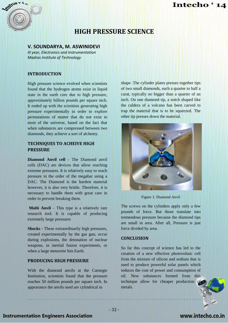
- 32 -
HIGH PRESSURE SCIENCE
V. SOUNDARYA, M. ASWINIDEVI III year, Electronics and Instrumentation Madras Institute of Technology
INTRODUCTION
High pressure science evolved when scientists
found that the hydrogen atoms exist in liquid
state in the earth core due to high pressure,
approximately billion pounds per square inch.
It ended up with the scientists generating high
pressure experimentally in order to explore
permutations of matter that do not exist in
most of the universe, based on the fact that
when substances are compressed between two
diamonds, they achieve a sort of alchemy.
TECHNIQUES TO ACHEIVE HIGH
PRESSURE
Diamond Anvil cell - The Diamond anvil
cells (DAC) are devices that allow reaching
extreme pressures. It is relatively easy to reach
pressure in the order of the megabar using a
DAC. The Diamond is the hardest material
however, it is also very brittle. Therefore, it is
necessary to handle them with great care in
order to prevent breaking them.
Multi Anvil – This type is a relatively rare
research tool. It is capable of producing
extremely large pressures
Shocks - These extraordinarily high pressures,
created experimentally by the gas gun, occur
during explosions, the detonation of nuclear
weapons, in inertial fusion experiments, or
when a large meteorite hits Earth.
PRODUCING HIGH PRESSURE
With the diamond anvils at the Carnegie
Institution, scientists found that the pressure
reaches 50 million pounds per square inch. In
appearance the anvils used are cylindrical in
shape .The cylinder plates presses together tips
of two small diamonds, each a quarter to half a
carat, typically no bigger than a quarter of an
inch. On one diamond tip, a notch shaped like
the caldera of a volcano has been carved to
trap the material that is to be squeezed. The
other tip presses down the material.
Figure 1: Diamond Anvil
The screws on the cylinders apply only a few
pounds of force. But those translate into
tremendous pressure because the diamond tips
are small in area. After all, Pressure is just
force divided by area.
CONCLUSION
So far this concept of science has led to the
creation of a new effective photovoltaic cell
from the mixture of silicon and sodium that is
used to produce powerful solar panels which
reduces the cost of power and consumption of
oil. New substances formed from this
technique allow for cheaper production of
metals.

- 33 -
IEA PROFILE
The Instrumentation Engineers Association, comprising the Instrumentation technocrats of
the prestigious MIT, is a student body, working towards the betterment of students in every
domain. The roots of the Association are Dr.J.Prakash, the HOD of Electronics and
Instrumentation, final year students‘ Faculty Advisor Mrs.C.Shanthi (Treasurer, IEA) and an
inevitable clique that comprises the Chairman, the Vice-Chairman, the Secretary and the Joint
Secretary under the guidance of other staffs, altogether striving for the progress of the
Association.
Education must not be confined to the classrooms. In order to make the students stay in
today‘s contention; the students must be exposed to a sufficient industrial ambience, peer-
peer learning, proper guidance about various career opportunities and whatsoever possible.
This entire process is ensured and enacted by the IEA.
A good career is every student‘s dream. The IEA helps the students to realise their dream by
scheduling various activities. Few such activities include aptitude tests, mock-interviews and
seminars, group discussion sessions and many other interactive sessions conducted by the
seniors, which will help the students get into the corporate world. The IEA in collaboration
with the Alumni Association not only increases the chances of bringing many companies but
also makes the students aware of various opportunities outdoor. At the same time, IEA, for
the purpose of feeding a healthy dose of balanced theoretical knowledge and industrial
knowledge, has been arranging many guest lectures on a variety of topics.
To enumerate a few of them,
1. Dr. M. Nazmul Karim, Head, Chemical Engineering department, Texas A&M
University- An introduction to control of biological processes
2. Mr. Sivagnanam, Latin America Distribution Head, Emerson- Control Valve sizing
The IEA, under the guidance of the HOD, has mentored the junior students on their summer
projects to help them gain expertise on the working of various instruments and components.
This motivation fed by the IEA, in addition to helping them get some knowledge under their
belts, also updates them with the modern technology.
IEA has put sedulous efforts for the success of its intra-college technical symposium, the
LIVEBEAT and now its inter-college technical symposium, the INTECHO. The latter is a
national level technical symposium that comprises various technical activities which would
bring the acing technocrats to light.
In sum, the Instrumentation Engineers Association can be likely called a democracy, for it is
the association of the students, by the students and for the students.
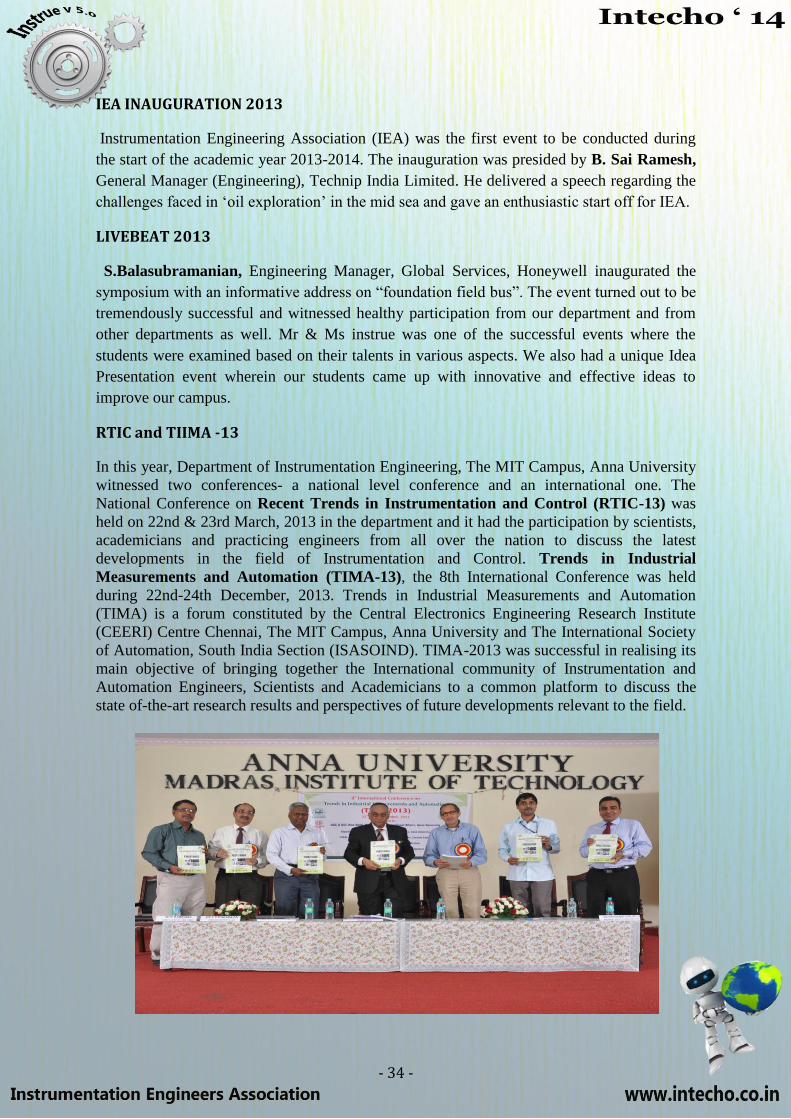
- 34 -
IEA INAUGURATION 2013
Instrumentation Engineering Association (IEA) was the first event to be conducted during
the start of the academic year 2013-2014. The inauguration was presided by B. Sai Ramesh,
General Manager (Engineering), Technip India Limited. He delivered a speech regarding the
challenges faced in ‗oil exploration‘ in the mid sea and gave an enthusiastic start off for IEA.
LIVEBEAT 2013
S.Balasubramanian, Engineering Manager, Global Services, Honeywell inaugurated the
symposium with an informative address on ―foundation field bus‖. The event turned out to be
tremendously successful and witnessed healthy participation from our department and from
other departments as well. Mr & Ms instrue was one of the successful events where the
students were examined based on their talents in various aspects. We also had a unique Idea
Presentation event wherein our students came up with innovative and effective ideas to
improve our campus.
RTIC and TIIMA -13
In this year, Department of Instrumentation Engineering, The MIT Campus, Anna University
witnessed two conferences- a national level conference and an international one. The
National Conference on Recent Trends in Instrumentation and Control (RTIC-13) was
held on 22nd & 23rd March, 2013 in the department and it had the participation by scientists,
academicians and practicing engineers from all over the nation to discuss the latest
developments in the field of Instrumentation and Control. Trends in Industrial
Measurements and Automation (TIMA-13), the 8th International Conference was held
during 22nd-24th December, 2013. Trends in Industrial Measurements and Automation
(TIMA) is a forum constituted by the Central Electronics Engineering Research Institute
(CEERI) Centre Chennai, The MIT Campus, Anna University and The International Society
of Automation, South India Section (ISASOIND). TIMA-2013 was successful in realising its
main objective of bringing together the International community of Instrumentation and
Automation Engineers, Scientists and Academicians to a common platform to discuss the
state of-the-art research results and perspectives of future developments relevant to the field.
- 35 -
STAFF PROFILE
RESEARCH PAPERS PUBLISHED AND PRESENTED
1. F Kiasi, J Prakash, SL Shah, presented a paper titled ‖An Alternative Approach to
Implementation of Generalized Likelihood Ratio Test for Fault Detection and Isolation ―,
Industrial & Engineering Chemistry Research,2013. 2. J Prakash, SR Jayasurian, published a paper on ”Design and Implementation of
Fractional-Order Controller for Fractional Order System”,in Recent Advancements in System Modelling Applications, 319-326,2013
3. V.Rajinikanth, K.Latha, published a research paper titled ―Controller parameter optimization
for nonlinear systems using enhanced bacteria foraging algorithm‖, in the field of Applied
Computational Intelligence and Soft Computing, 2012. 4. N. Pappa, T.Babu published a paper on ‖Design of Robust PID Controller using Hybrid
Algorithm for Reduced Order Interval System‖,Asian Journal of Scientific Research,Vol 5
(3), 108-120, 2012. 5. K. Kamalanand and S. Srinivasan, authored a paper on ―Modeling of Normal and
Atherosclerotic Blood Vessels using Finite Element Methods and Artificial Neural
Networks‖, in World Academy of Science, Engineering and Technology, Vol. 60, pp. 1314-
1317, Dec. 2012
6. SakthivelMurugan. S and Natarajan. V, published a paper on ―Implementation of Threshold
Detection Technique for Extraction of Composite Signals against Ambient Noises in
Underwater Communication using Empirical Mode Decomposition‖, Fluctuation and Noise
Letters, Vol.11, No.4, 2012
7. Esakkiappan, C. and Thyagarajan, T. Presented a paper titled , ―Improved Auto Tuning for
Integrating Process with Time Delay using Relay Feedback Test‖, Mediterranean Journal of
Measurement and Control,2012.
8. K. Kamalanand, P. MannarJawahar (2012), presented a paper on ―Estimation of HIV-1 Viral
Load from CD4 Cell Count using Bacterial Foraging Optimization and Three Dimensional
HIV/AIDS model‖, in Proceedings of 1st Asian Conference on Hepatitis B and C, HIV and
Influenza, 18 – 19 May 2012, Beijing China
AWARDS AND HONOURS
Dr.T.Thyagarajan has been awarded THE IEEE GOLD/WIE, MENTOR AWARD
2008.
He also received the certificate of Appreciation for contributions to IEEE as Chair,
2010-2012
Dr. J.Prakash has been awarded ISA-Emerging Leader 2011
He is also honored with DST BOYSCAST fellowship
Mr.Kapil Arasu received Canadian common wealth scholarship
- 36 -
STUDENT ACHIEVEMENTS
FOURTH YEAR
Nagineni Varun Chowdary, Sukanya. S presented a paper titled ―Robust controller design for
Integrator plus time delay systems using Kharitonov theorem‖ at the 8th International
conference on Trends in Industrial Measurement and Automation (TIMA – 2013.)
Nagineni Varun Chowdary, Sukanya. S presented a paper titled ―Effect of Heart rate on the
accuracy of Oscillometric blood pressure measurement‖ in the National conference on Recent
Trends in Instrumentation and Control (RTIC – 2013).
Sukanya. S scored 328/340 in GRE.
Nagineni Varun Chowdary scored 316/340 in GRE.
B. Koushik scored 316/340 in GRE.
Swaminathan T.C came first in Pyramix at Shaastra cube open, IIT-M. He has delegated
various cube competitions in various institutions across India including IIT-D, IIT- Guwahati,
BITS Pilani, BITS Hyderabad, NIT Trichy etc and has won several awards.
S. Sriramana and B. Koushik were a part of the zonal winning chess team, 2012. The team
was further ranked 4th in the State level Chess championship
B. Koushik was a part of the chess team which came 2nd
in the 2013 zonal Chess
championship.
T. Piranava scored 314/340 in GRE.
Vignesh. B scored 315/340 in GRE.
Rizwana Begum. S won second place in table tennis at zonal level.
THIRD YEAR
S. Shri Shankari, A. Girish Gowtham published a paper titled ―Signal Strength Enhancer‖ at
ICEEECSME, 10th IRAJ International Conference.
Nithyadharshini.S, Keerthana.V won second prize in Paper presentation at ―Electronica‖,
Kodaikanal Institute of Technology.
Srihari Vignesh.R scored 326/340 in GRE.
Rudhrapriya.R won second place in Badminton at Chemfest‘ 13 held at Chengalpet Medical
College.
Madhumitha.V won silver medal in Badminton Zonal championship held at MIT.
SECOND YEAR
Vasanth Kumar was awarded Young scientist award at the National level by the Tamil Nadu
science forum.
C.R. Vidhya Prasad has secured first place in quiz at the state level talent expo conducted by
the Tamil Nadu education board.
Aishwarya. M has participated in the Common wealth games for Taekwondo. She went to the
Indian camp for Olympics and has won several gold and silver medals in the National and
State level.
P. Allwin Bebeto won bronze in Hockey at the zonal level.