Embed Size (px)
Citation preview
E30love.com Euro Clock 'Plug & Play' Install Instructions: 13 Button OBC Thank you for ordering the euro clock install kit. This kit allows you to install a BORG analog clock into your BMW E30, E24 or E28. Note: If your vehicle is equipped with a 6 button OBC (on board computer), you need to use the "6 Button" Kit & Instructions. Please confirm you have the correct kit for your vehicle. If not, please contact [email protected]. 13 Button OBC Replacement Instructions: Credit: This install guide was written by “Garagistic.com” - an excellent e30 supply shop. We’ve modified the instructions slightly.
Tools needed to install euro clock
● flashlight
● small Phillips screwdriver
● Phillips regular size
● flat head regular size
● tools to remove your head unit (head unit specific)
● connectors
● wire cutters
● wire crimper
● philips screw driver
Step 1: Disconnect Battery + OBC removal: Make sure to disconnect your e30 battery.
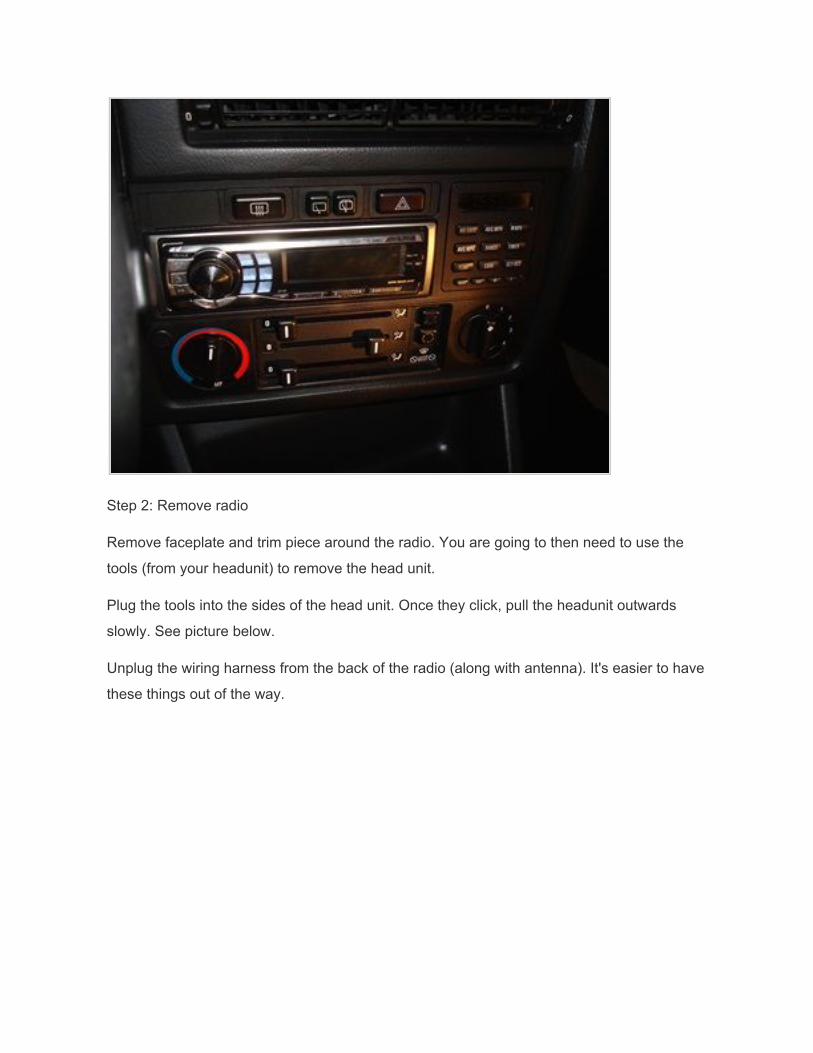
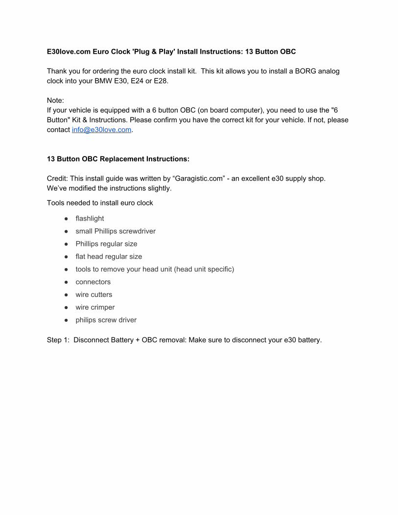
Step 2: Remove radio
Remove faceplate and trim piece around the radio. You are going to then need to use the
tools (from your headunit) to remove the head unit.
Plug the tools into the sides of the head unit. Once they click, pull the headunit outwards
slowly. See picture below.
Unplug the wiring harness from the back of the radio (along with antenna). It's easier to have
these things out of the way.
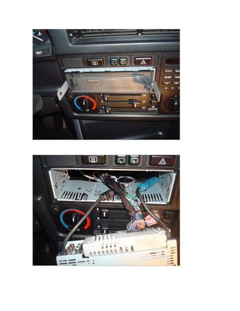
Step 3 Pop out the switches from behind
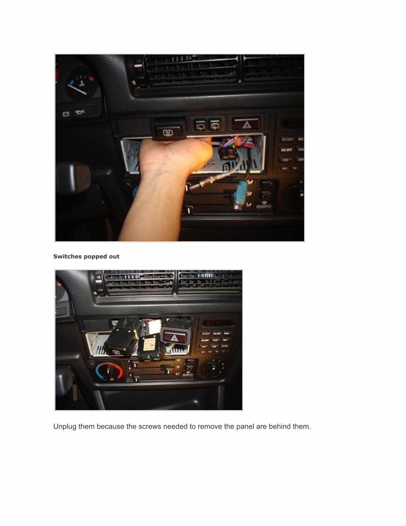
Switches popped out
Unplug them because the screws needed to remove the panel are behind them.
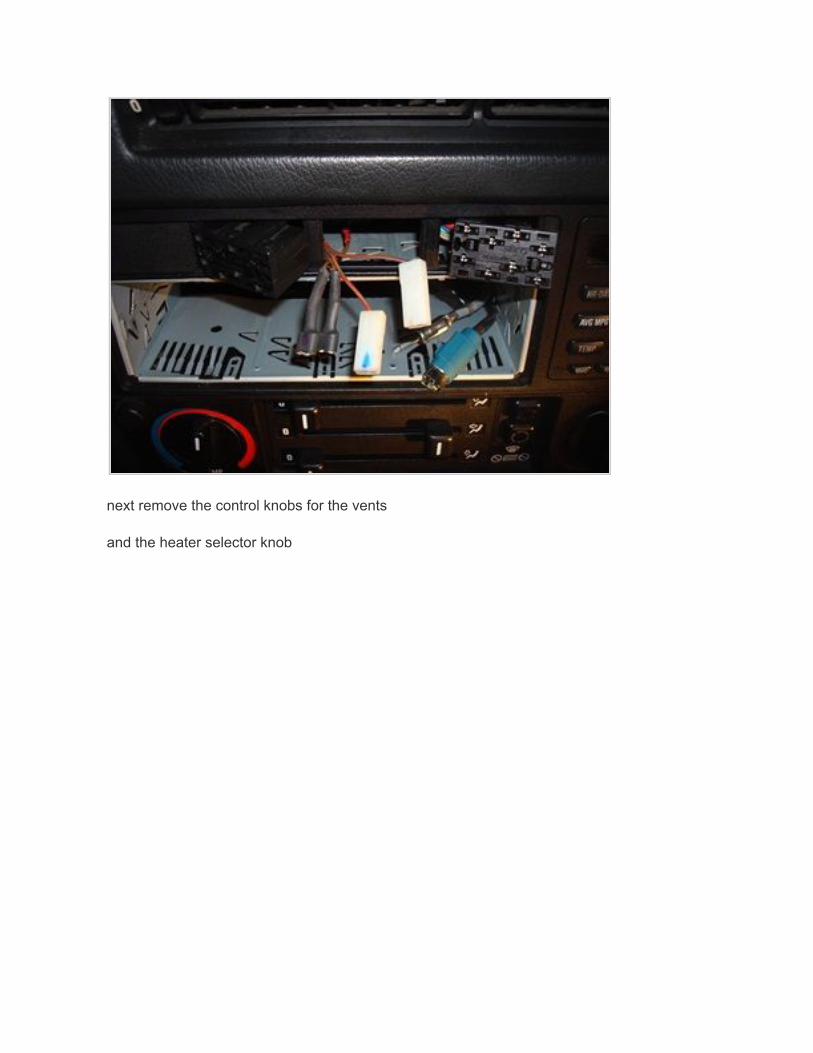
next remove the control knobs for the vents
and the heater selector knob
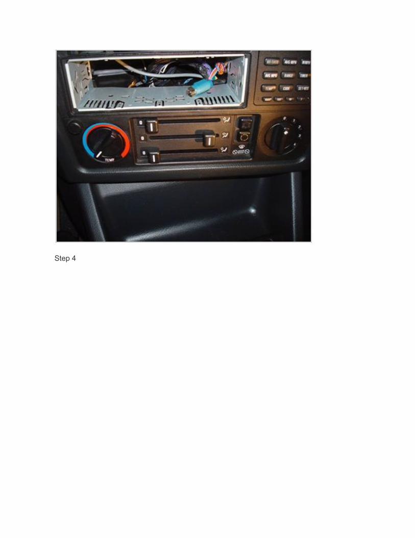
Step 4
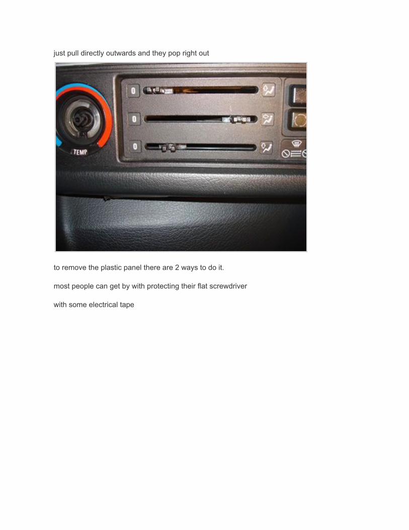
just pull directly outwards and they pop right out
to remove the plastic panel there are 2 ways to do it.
most people can get by with protecting their flat screwdriver
with some electrical tape
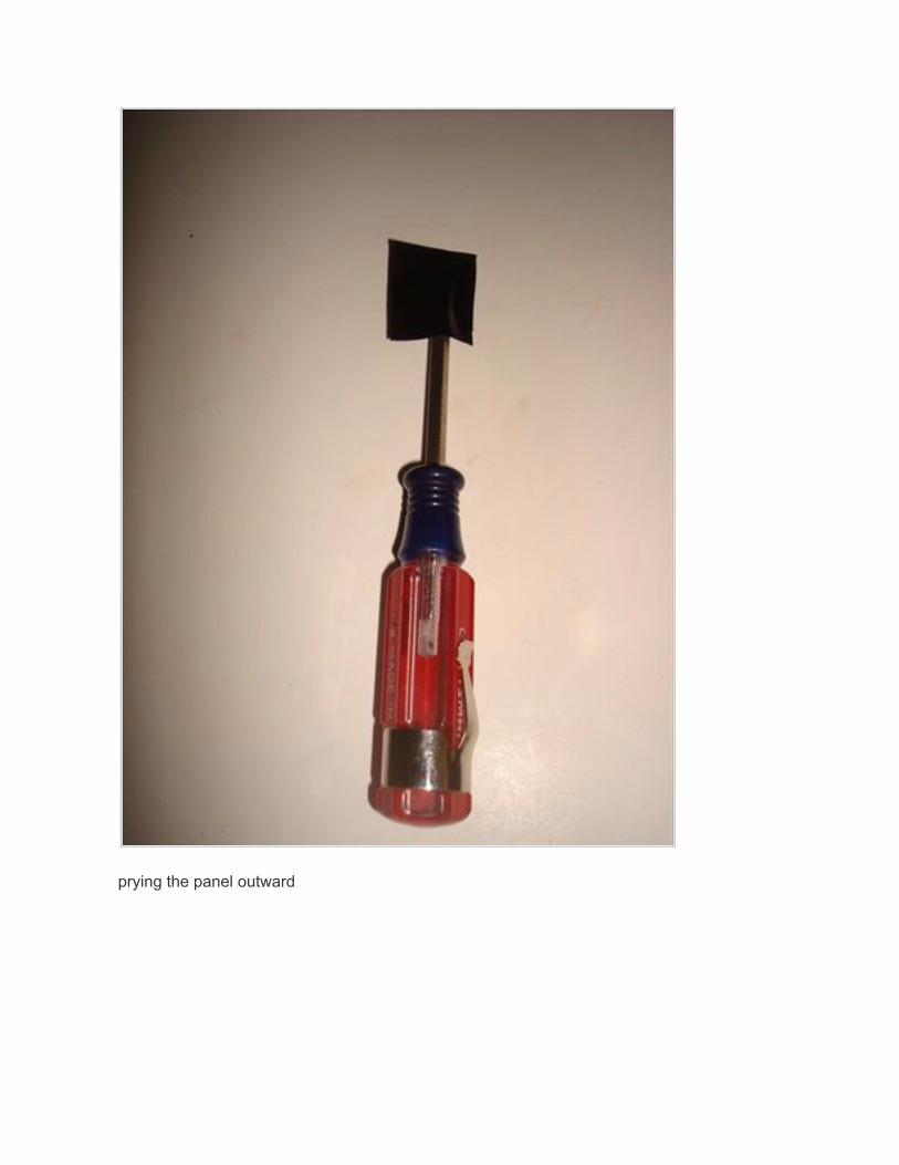
prying the panel outward
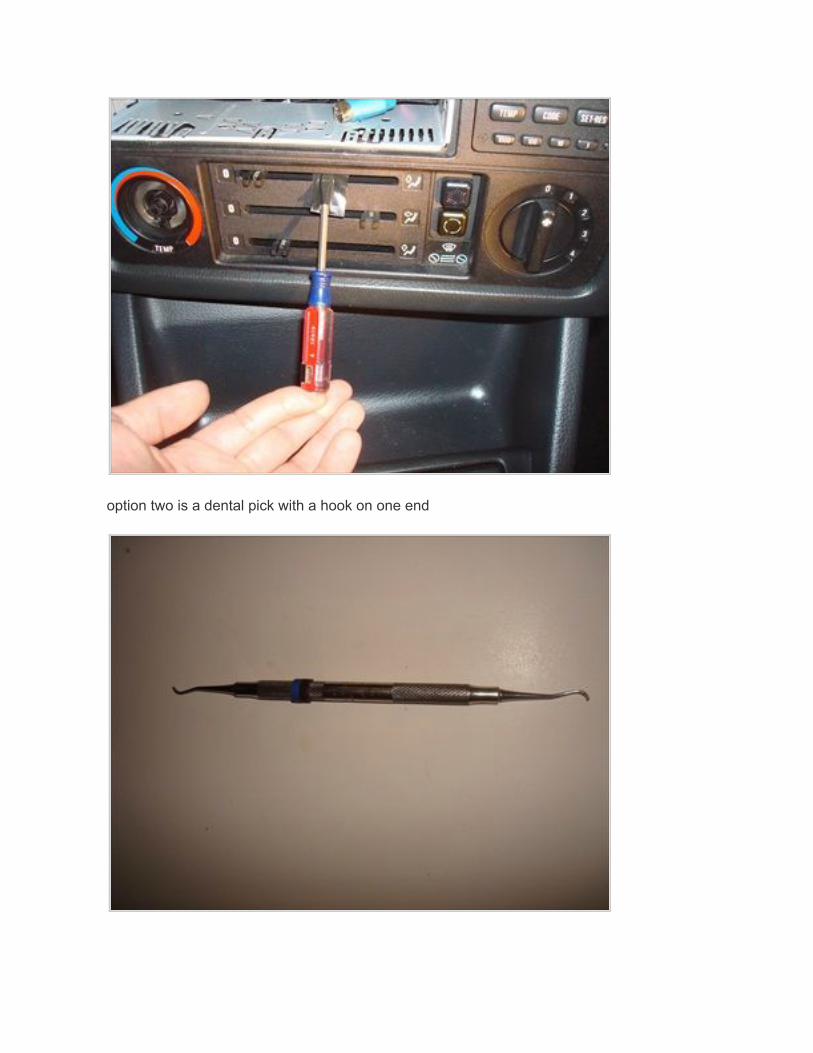
option two is a dental pick with a hook on one end
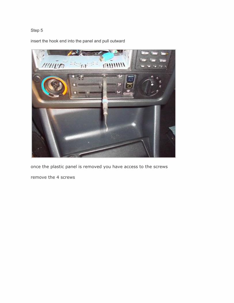
Step 5
insert the hook end into the panel and pull outward
once the plastic panel is removed you have access to the screws
remove the 4 screws
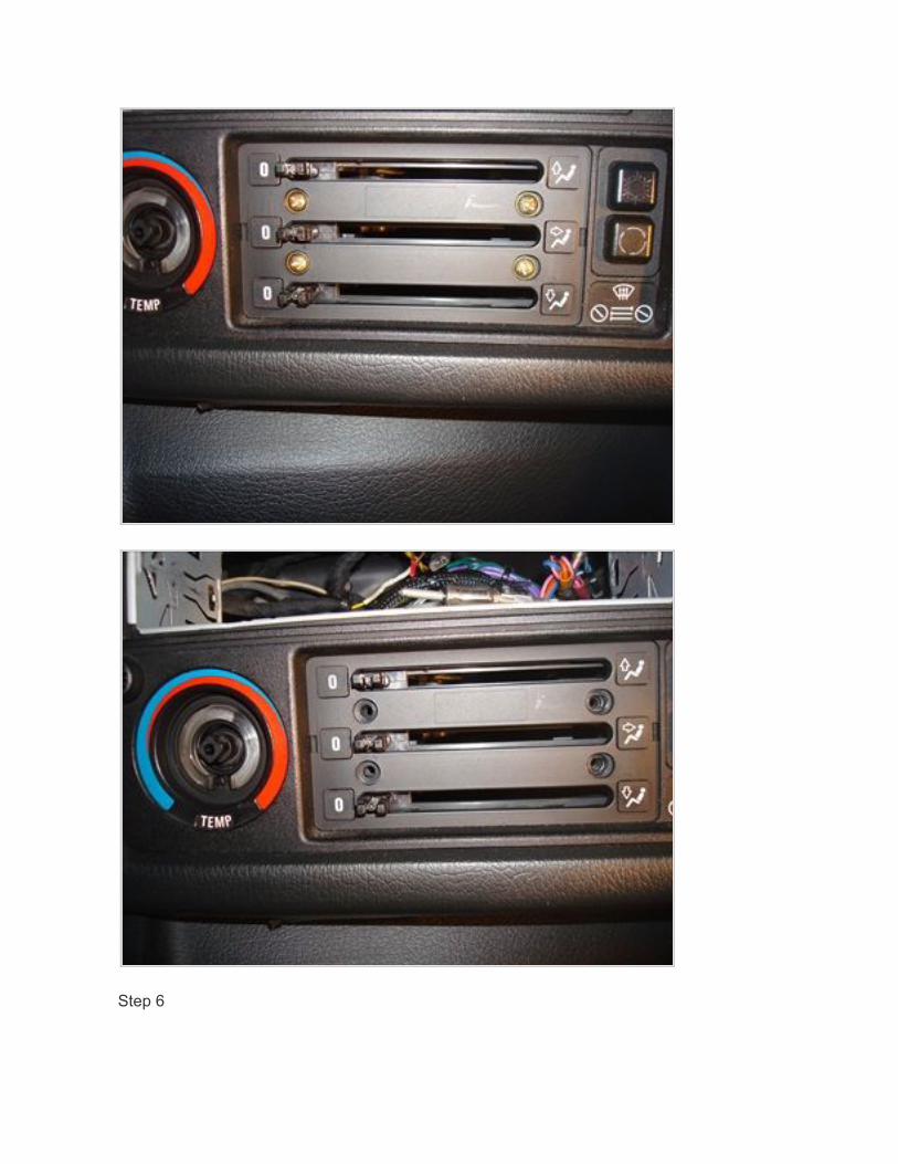
Step 6
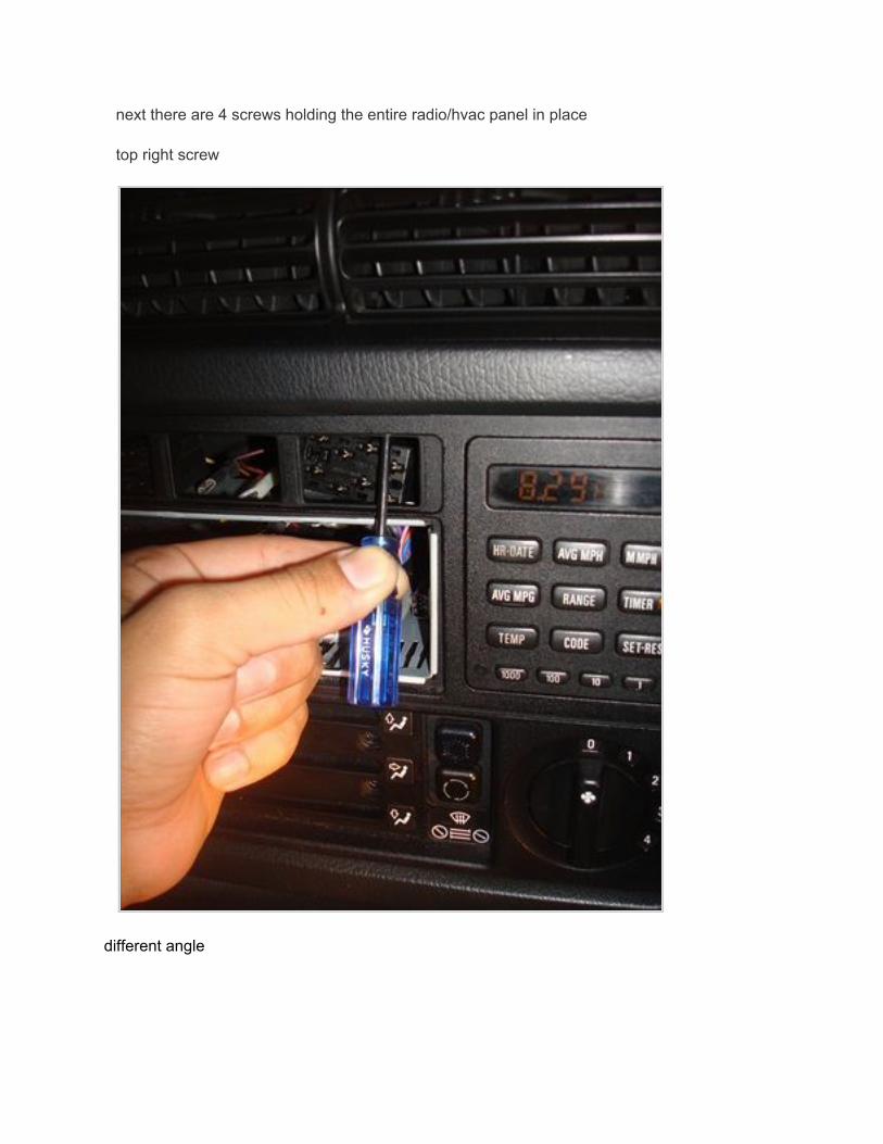
next there are 4 screws holding the entire radio/hvac panel in place
top right screw
different angle
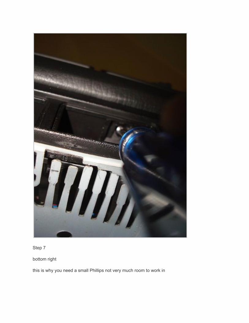
Step 7
bottom right
this is why you need a small Phillips not very much room to work in
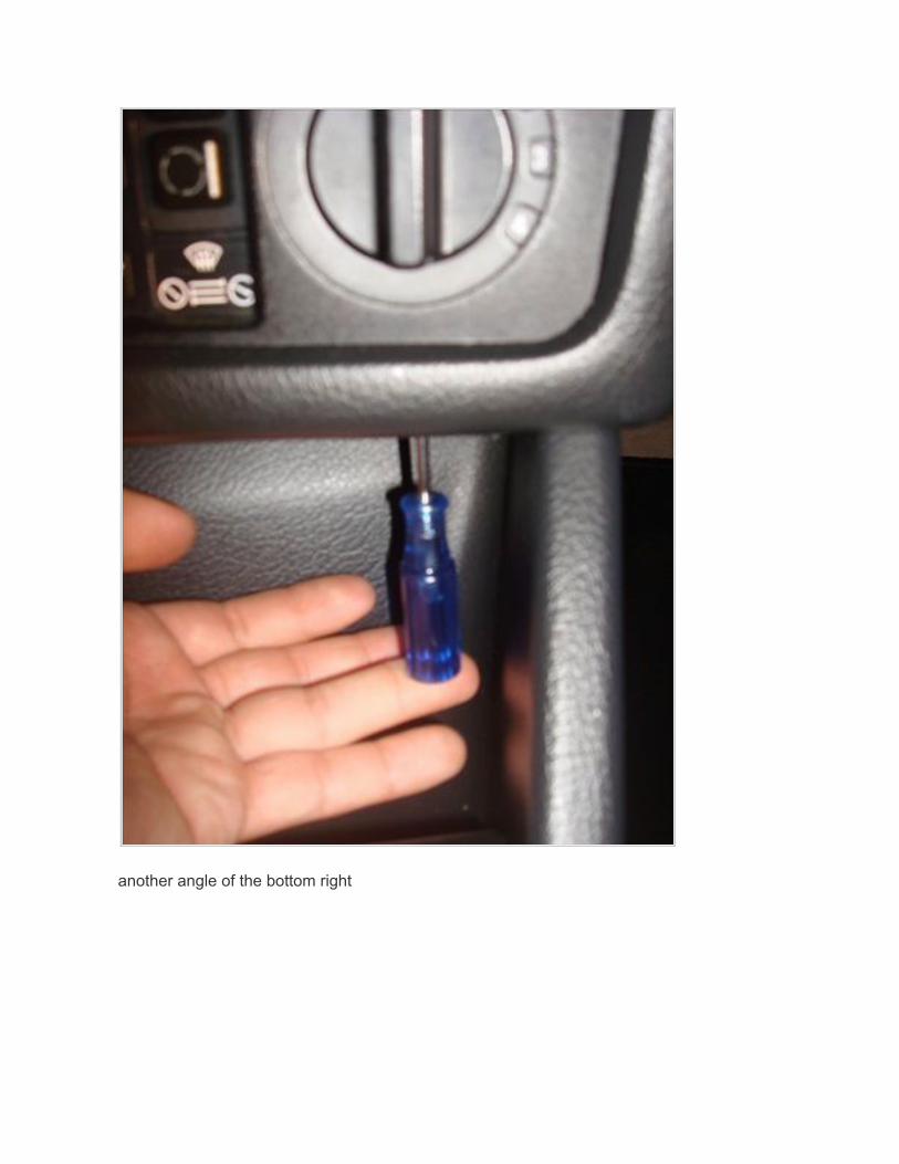
another angle of the bottom right
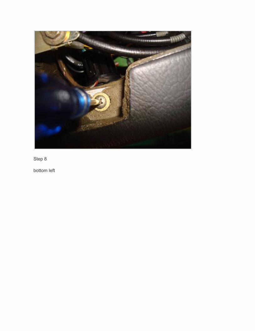
Step 8
bottom left
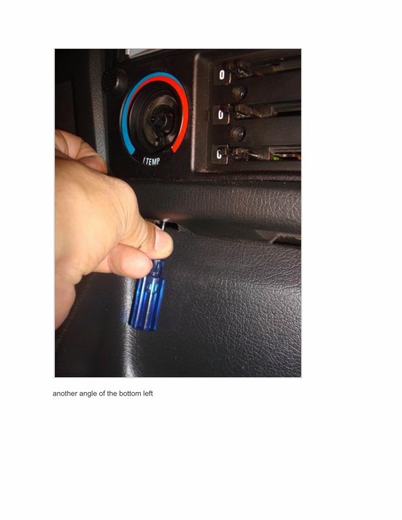
another angle of the bottom left
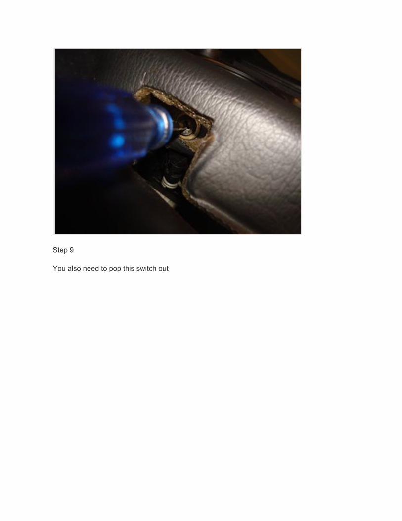
Step 9
You also need to pop this switch out
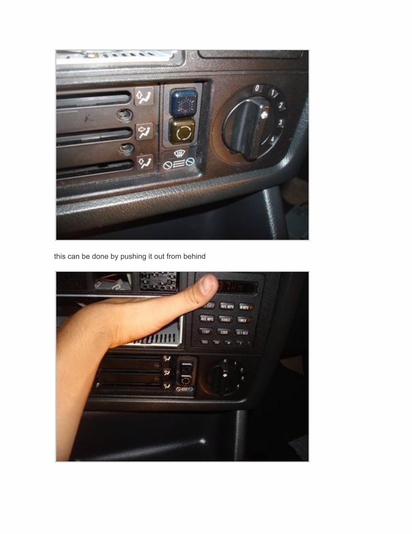
this can be done by pushing it out from behind
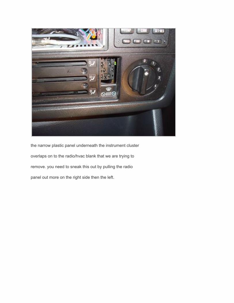
the narrow plastic panel underneath the instrument cluster
overlaps on to the radio/hvac blank that we are trying to
remove. you need to sneak this out by pulling the radio
panel out more on the right side then the left.
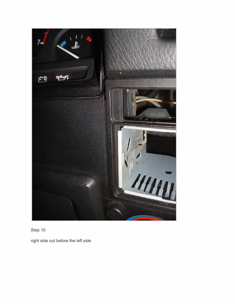
Step 10
right side out before the left side
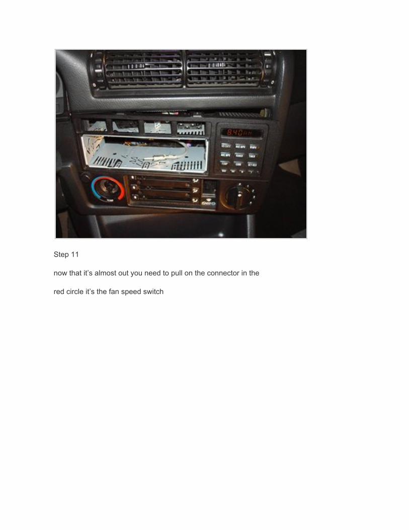
Step 11
now that it’s almost out you need to pull on the connector in the
red circle it’s the fan speed switch
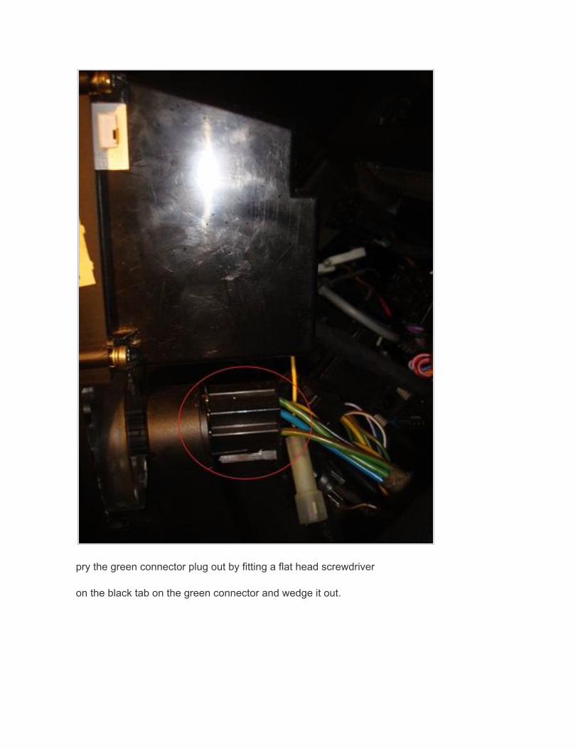
pry the green connector plug out by fitting a flat head screwdriver
on the black tab on the green connector and wedge it out.
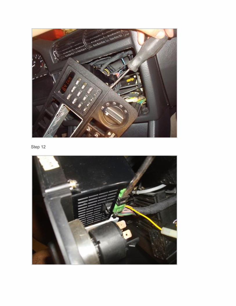
Step 12
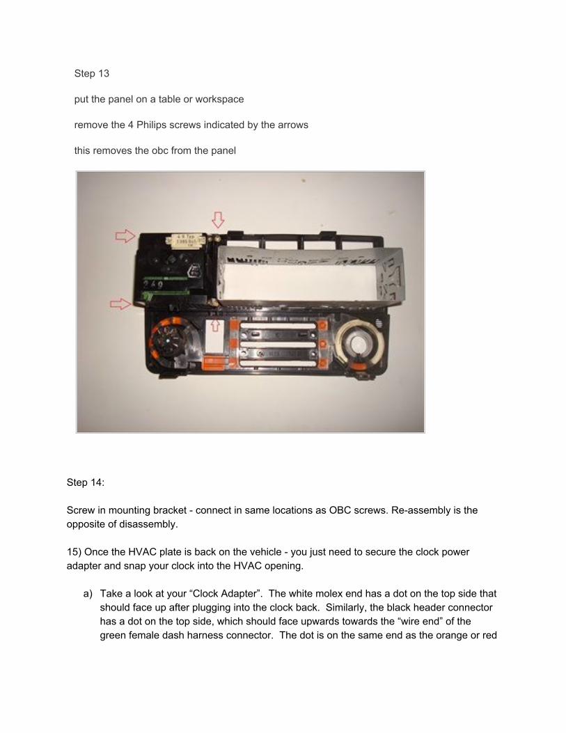
Step 13
put the panel on a table or workspace
remove the 4 Philips screws indicated by the arrows
this removes the obc from the panel
Step 14: Screw in mounting bracket - connect in same locations as OBC screws. Re-assembly is the opposite of disassembly. 15) Once the HVAC plate is back on the vehicle - you just need to secure the clock power adapter and snap your clock into the HVAC opening.
a) Take a look at your “Clock Adapter”. The white molex end has a dot on the top side that should face up after plugging into the clock back. Similarly, the black header connector has a dot on the top side, which should face upwards towards the “wire end” of the green female dash harness connector. The dot is on the same end as the orange or red
wires. This end should point upwards towards the ceiling. This direction is important for proper clock function. Please visually confirm this alignment.
b) Take the black “Clock Adapter” end - line up the dot with the top/wire side of the plug and slide the 12 connectors into the female plug.
c) Wrap the zip tie around the connected plugs and tighten snugly so the two are secured together.
d) Cut off loose end of zip tie. e) Insert white Molex end into Clock with dot facing upwards. Grip the plug by the white
plastic housing, and push gently inwards until connectors slide together snugly. If you look closely, you’ll see the clock has 4 posts, and 1 missing position. This will line up with your connector. Note: push in slowly and directly. Be gentle if you try to remove the plug later. The terminals make a tight seal with the clock terminals for electrical security. Pulling directly on the wires could damage the adapter.
f) Insert your clock gently into the OBC opening until the top and bottom tabs click. g) Apply the clock faceplate onto clock face. h) Reconnect battery. i) Start vehicle and test clock - set time with + and - buttons, test amber backlight light
goes on when headlights are turned on. If your backlight does not come on, please remove clock and verify you have a ‘good’ lightbulb.
You’re done! Enjoy your clock. Any questions please email [email protected].
- E3L


