Embed Size (px)
Citation preview

1. What is the timeline for rollout of IEEE Std 1547™-2018 compliant smart inverters in the marketplace?
UL convened a Task Group (TG) in January 2020 comprised of representatives from
National Labs, Electric Utilities, Inverter Manufacturers, General Interest, and Nationally Recognized Testing Labs (NRTLs) (details here) to discuss and revise the existing UL 1741 Ed. 2, an UL certification standard for smart inverters, in order to align it with the new IEEE Std 1547™-2018 and IEEE 1547.1-2020 standards requirements and test
procedures for distributed energy resources. The UL 1741 Ed. 2 revision was published September 16, 2020, shortly after the publication of IEEE 1547.1-2020 and the IEEE
1547-2018 Amendment. The revisions of UL 1741 Ed. 2 are as follows:
• The existing Supplemental SA will remain within UL 1741 for the time being. • A new Supplement SB was added that directly refers to the IEEE 1547.1-2020
test procedures.
• For inverters capable of meeting requirements of existing codes like CA Rule 21 and HI Rule 14H, the Supplement SA was modified to allow for use of IEEE 1547.1-2020 test methods as an alternative to existing Supplement SA test methods, as a means to move towards Supplement SB/ IEEE Std 1547™-2018
and IEEE 1547.1-2020 compliance. • For inverters rated for compliance with the new IEEE Std 1547™-2018 and IEEE
1547.1-2020, certification via Supplement SB will be required.
The revisions of UL 1741 Ed. 2 are available for use immediately at their publication. Inverter manufacturers choose which Supplement to certify their equipment to as they deem appropriate and as the market requires. The UL 1741 website with the new
Supplement SB can be found here.
Inverter manufacturers have started to implement some substantial changes in their
equipment, to firmware and possibly also to hardware, to meet all of the IEEE Std 1547™-2018 requirements (e.g., phase jump and ROCOF ride-through). Therefore, it was expected that new products to market would not be generally available until at least 18 months after publication of IEEE 1547.1 and the UL 1741-2020 Ed. 2 revision. As
this process went on, a significant number of difficulties with the test procedures specified in IEEE 1547.1 and required for UL 1741 SB certification have been identified. The UL TG then reconvened to resolve the 111 identified issues, creating a 27-page Supplement SB revision proposal to provide guidance for the application of the IEEE-
1547-1-2020 test standard. Publication of a 3rd Edition of UL 1741 is expected for Q3/2021. The intention of the Supplement SB revision document is to promote a common understanding and application of the new requirements and to maximize consistency in DER response to grid events. This means that effective dates for IEEE
Std 1547™-2018 of sooner than April 1, 2022, could create a technical barrier for non-certified inverters to interconnect to the grid. Once available, certified products will be listed on NRTLs’ websites. The below timeline summarizes the above information.

The Minnesota public utilities commission (PUC) has decided under MN PUC, ORDER 159427-01, Docket E-999/CI-16-521 to monitor the progress made to bring IEEE Std 1547™-2018 certified inverters to market, and the order would also issue a “Commission Notice” to determine the effective date at which their Technical Interconnection and Interoperability Requirements (TIIR) enter in full effect. Other PUCs
are following suit to adapt their timelines with the availability of certified inverters in the market.
2. Can default smart inverter settings be deployed effectively across a wide range of feeders?
Universal settings can be selected, but the more location-specific the settings, the more benefit is possible. For example, unique settings for each utility (or even for each
feeder, etc.) allow a better fit to the situation and hence, more benefit. If a uniform function and setting is desired, the utility must be willing to accept that the DER may over- or under-compensate for system conditions that don’t correspond with the system condition on which the uniform setting is based. Modeling results have shown that
selection of settings is highly dependent on system conditions, and a setting optimized for one condition will be less than optimal for another condition.
Selection of voltage support functions depends on the desired objectives, existing voltage regulation practices, and the characteristics of the specific feeder and distributed energy resource (DER) implementations. If most of the DER systems are large in size (> 500kVA), then the interconnection may be modeled to choose an
appropriate setting for that specific application. One approach could be to have DER “cancel” its own voltage impacts, but not mitigate system voltage issues. This may be desired if there is sufficient headroom in the existing range of steady state voltage for the long-term forecasted load and generation. If this approach is desired, tailored fixed
power factor and watt-var are good options. However, these are not best applied with a uniform setting as the system characteristics (X/R, Reference Point of Applicability (RPA), and Short Circuit Ratio) at the specific location impact the desired setting. If it is

desired to mitigate system voltage issues that are not caused by the DER, then applying a tailored volt-var setting enables the DER to mitigate system voltage issues. In all cases, the DER must have sufficient reactive power capability to deliver/absorb the
needed reactive power to mitigate the voltage issue. Inadequate reactive power capability will limit the ability of DER to correct system voltage issues.
3. How important is the existing utility voltage regulating philosophy to the selection of DER functions and settings?
The typical operating voltage level at the DER location on a feeder can have
significance to the selection of the regulation mode and the settings. The voltage
profile, without DER, depends not only on feeder loading level, but also the voltage
management strategy employed by the utility. Some strategies are:
1. The primary substation bus voltage is not regulated by substation transformer on-
load tap-changers, and feeder voltage regulators are not used. I.e., the
distribution system is unregulated and feeder voltages are subject to both feeder
loading and transmission voltage variations.
2. As in #1, but switched capacitor banks are used on the feeders to regulate
voltage directly using voltage-based switching controls, or indirectly where the
capacitor banks are switched based on current, reactive power flow, or implied
loading based on time of day or ambient temperature.
3. Substation bus is not regulated, as in #1, but voltage regulators are used at each
feeder head but not elsewhere on the feeders. Capacitors are not used to
regulate voltage.
4. Substation bus is not regulated, as in #1, but voltage regulators are used at each
feeder head as well as at downstream locations on the feeders.
5. Substation bus is not regulated, as in #1, but voltage regulators are used at each
feeder head but not elsewhere on the feeders. Capacitors are used to regulate
voltage along the feeders.
6. Substation bus voltage is regulated by on-load tap-changers and no other
voltage regulation is implemented.
7. Substation bus voltage is regulated by on-load tap-changers and switched
capacitors provide additional downstream voltage regulation
This above list is not exhaustive, but it serves to illustrate the variety of distribution
voltage regulation strategies applied by utilities, with or without the presence of DER.
As the strategies will have a significant impact on the feeder voltage profile, they are a
critical consideration when choosing DER functions and settings. Voltage-independent
functions, such as watt-var and fixed power factor, may be appropriate in situation
where the voltage profile over time is not very well known.

4. How important is the DER location on the distribution system when
selecting functions and settings?
The location of a DER along the feeder is a substantial determinant of the driving point
impedance seen from the DER Reference Point of Applicability (RPA). The resistive
component of this impedance determines the amount of voltage change that results
from DER active power output changes. The reactive component determines the ability
of reactive power to create a mitigating voltage change component. Therefore, the DER
electrical location on the system is a very important consideration.
At the head of the feeder (near the substation), the impedance is quite small, relative to
that of the source, defined primarily by the rating and percent impedance of the
substation transformer. In most situations, the rating of the transformer is substantially
greater than the aggregate rating of DER connected to the distribution system served by
the substation. Moving away from the substation, the impedance of the feeder
increases due to the substantial feeder impedance per 1000’. The ratio of reactance to
resistance (X/R) decreases with distance. At the feeder head, the X/R is defined
primarily by the substation transformer, and for small and medium power transformers
this ratio is typically 20 or greater. The X/R of the feeder itself is much lower, so as the
distance along the feeder increases, the X/R ratio decreases. The trend in X/R
depends on how the feeder is designed. Some feeders, particularly those in systems
designed for flexibility to use alternate far-end feeds during contingencies (typical of
feeders in urban and suburban areas), use a constant conductor size for all main line
sections of the feeder. Other feeders, particularly those that do not have an alternate
feed (e.g., rural circuits), are designed with tapered conductor sizes that decrease in
size and ampacity with distance from the substation.
5. Does EPRI have any recommended autonomous smart inverter
settings to help further enable more DER connections?
EPRI has both simplified tools and full system analysis techniques for determining the best DER functions and associated settings. The definition of “best settings”, however, depends on the specific goals or operating objectives in the region. Most utilities are considering targeting a voltage-related objective (improve voltage flatness, reduce
overvoltages, etc.) with DER advanced autonomous functions. Other potential goals include alignment with conservation voltage reduction (CVR) systems, improved hosting capacity, maximizing deferral of new distribution infrastructure investments, and minimizing system losses.
For smaller DER system sizes (residential and small Commercial and Industrial) where developing tailored settings are not feasible and there are no existing or near-term
voltage regulation issues, fixed power factor or unity power factor are recommended. While unity power factor does nothing to mitigate voltage issues directly related to the DER, it helps to maximize system capacity, reduce system losses, and minimize var consumption from the T&D system. A fixed power factor may help to mitigate voltage

issues created by the DER itself, but likely increases var consumption, reduces system capacity, and increases losses. If var consumption is a key consideration, then a default IEEE Std 1547™-2018 volt-var function may help to minimize var consumption, but care
must be taken to assure that the volt-var setting is coordinated with other regulating equipment. For example, some feeders keep elevated voltages near the substation to maintain voltage on the end of the feeder. If volt-var is applied to a DER located near the substation, it may act to absorb vars for the elevated voltages outside its deadband
and cause excessive var demand. In this case, it may be desired to apply a different default function based upon the DER location along the feeder.
For smaller DER system sizes with existing distribution system medium voltage (MV) regulation issues, then it is recommended that line voltage regulator, LTC, and capacitor bank settings adjustments be considered as the first line of defense. This equipment is ideally suited to manage feeder voltage without some of the negative consequences
associated with using DER for voltage regulation. If adjustments of existing equipment are not able to mitigate the system voltage issue, then the use of a default IEEE Std 1547™-2018 volt-var setting is recommended, since it is possible to resolve voltage issues not directly related to the DER itself. It is recommended that some circuit
modeling be performed to assure that the DER can provide adequate reactive support to mitigate the system voltage regulation issue. According to IEEE Std 1547™-2018, the reference point of applicability (RPA) for systems less than 500kVA in size is typically at the inverter terminals. EPRI research has shown that the secondary cabling and
interconnection transformer can greatly influence the volt-var curve efficacy, as seen from the primary side of the interconnection transformer.
For larger DER systems sizes where system voltage regulation is an issue, it is recommended that the interconnection analysis include consideration of advanced functions, such as volt-var or watt-var, to assess the system behavior. A range of settings should be evaluated to find the best setting for the specific application. If this is
done during the interconnection process with inclusion of all the existing DER, then each subsequent DER application should be tailored for the desired objective. This is feasible until the DER reactive power functionality cannot adequately mitigate the voltage issues and other mitigations become necessary. It is recommended that utilities
should build the capability to perform time-series or statistical analysis to fully assess the effectiveness of advanced DER functions during a variety of system load and DER output conditions.
6. What are the recommendations for how to study and determine SI settings for each site?
Site-specific settings provide the highest degree of optimization and utilization of smart
inverter capabilities, but they are only practical for larger systems that go through a formal interconnection analysis. Depending on the desired objective, full assessment typically requires power flow analysis during a broad set of anticipated loading periods and DER operating points. A thorough process for analyzing a particular site to
determine best settings (based on utility goals) is relatively straightforward but involves

numerous time series power flow simulations. Site-specific settings should be viewed as a temporary solution until a control system (DERMS) can be deployed that enables remote adjustment of setpoints or real time control which allows for more optimal usage
of the DER reactive power capability. Distribution system changes are always occurring (load growth/shrinkage, DER additions/retirements, circuit changes, etc.), which would prompt reconsideration of the best site-specific settings. Frequent reassessment and truck-rolls to reconfigure DERs is impractical for all but the very largest DERs.
7. How important is the interconnection transformer and secondary
system (low voltage) impedance to selection of functions and settings?
The ability of secondary-connected DER to achieve desired grid support at primary voltage will depend on secondary voltage system conditions. Selection of the DER functions and settings used must consider the overall secondary impedance to compensate for the “electrical distance” of the primary system node from the point of
interconnection, where the RPA is at the terminals of the DER system rather than at the primary PCC. This typically applies for small DER systems or those that are designed not to export more than 500kW of active power to the grid.
Feeders that host a large amount of DER, composed either of a few larger sites or an
aggregation of many sites, can use DER functions to support the distribution system.
The functions and settings can be selected to have a desired impact for the benefit of
more than simply the local secondary voltage where the DER is interconnected. It
should be noted, however, that any functions applied to a significant amount of DER
capacity, regardless of intention of meeting voltage objectives at the primary,
secondary, or both levels, may affect performance of feeder voltage regulation
equipment (e.g., voltage regulators, switched capacitor banks). Settings selection
should be intentional to recognize the primary and secondary grid impacts with respect
to utility regulating equipment. Functions selected to meet primary level voltage
objectives will likewise have impact on secondary voltage, sometimes significantly.
8. How can utilities guarantee that the DER site owners will not change
these settings?
Preventing settings changes cannot be guaranteed, but can be detected, penalized, and corrected. EPRI’s interconnection guidelines and integration research recommend
utilities assume DER settings could be changed, intentionally or accidentally, until there is confidence that the frequency of discovering these changes diminishes.
EPRI has developed data analytic algorithms that use Advanced Metering Infrastructure (AMI) interval data (no communication to the DER required) that can determine many of the functions and settings of the DER. The intent is for these algorithms to run in the background at the utility, compare to presumed settings and flag mismatches for follow-
up. Not all settings can be determined in this way, such as ride-through settings.

In addition, since the communication interface to IEEE Std 1547™-2018 compliant smart inverters is open and standardized, EPRI is developing software tools that enable utilities and their partners to independently check the settings of any DER.
9. Doesn't every inverter provide anti-islanding protection? How is this a
"smart inverter" function that differs from normal UL 1741 anti-islanding requirements? Is there a way to disable anti-islanding detection?
Unintended island or anti-islanding protection is ubiquitous. It is considered a protection function, not a grid support function. UL 1741 SA8 anti-islanding protection defines the test procedure for unintentional islanding with grid support functions enabled. Table
SA8.1 shows combinations of different smart inverter functions that need to be active during anti-islanding tests. Anti-Islanding is not a configurable function per IEEE Std 1547™-2018, so in the field, it is intended to be always active and unchangeable. There are, however, some IEEE Std 1547™-2018 tests that require anti-islanding to be
momentarily disabled during the certification tests at NRTLs, revealing that there is some way (not standardized) to disable it.
10. What is the probability of an unintentional island forming through the application of all the smart inverter functions (e.g. Cat III and FreqWatt)
compared with “dumb” inverters, and how would specialized studies be performed for those projects with high risk?
EPRI is performing extensive laboratory testing of inverters to investigate the impact of grid support functions and motor loads on inverter on-board islanding detection capability. Based on three 1-phase and two 3-phase inverters tested in the lab, grid
support functions (GSF) do not increase the risk of unintended islanding. However, tests revealed that motor load can significantly delay the inverter run-on-time (RoTs) compared to passive RLC load bank condition.
This conclusion is also supported by results from islanding detection research with NYSERDA, Sandia, Mike Ropp, AIT and 12 utilities. The report, “Performance assessment of inverter on-board Islanding Detection with multiple testing platforms,”
3002014051, April 2020, includes discussion on screening processes. To summarize why GSFs do not conflict with island detection, an in-progress technical brief, “Does Inverter Grid Support Interfere with Islanding Detection?”, will be available soon.
The presence of motor load does extend the inverter run-on-times (ROTs). It is also notable that utilities may allow longer trip times, as long as voltage and frequency are within limits. Reclose delay may be required. For example, some utilities delay reclose
for 8 seconds, which gives them enough time to execute disconnects using SCADA. Reclose delays are possible in regions where momentary outage events, such as lightning, are relatively rare. For example, it may not be possible to delay reclose in places like Florida where lightning is prevalent.
References:
• Understanding Smart Inverter Functions’ Impact on Islanding Detection. EPRI, Palo Alto, CA: 2018. 3002012986.
• Unintentional Islanding Detection: Impact of Grid Support Functions and Motor Loads. EPRI, Palo Alto, CA: 2019. 3002015745.
11. Are the anti-islanding settings fixed settings or changeable?
The corresponding anti-islanding settings (like gain) can only be changed by the manufacturer. These settings are not like fixed PF or volt-var which can be adjusted by
installer or operator.
12. Have the NRTLs tested all the various inverters’ anti-islanding
schemes to make sure they cannot mask each other’s algorithms and not trip?
Certification tests at NRTLs are performed for one inverter at a time. NRTL tests do include combination of inverters from different manufacturers. EPRI’s islanding tests
includes multiple 1-phase and 3-phase inverters running in parallel. The objective is to investigate the impacts of mixing of different smart inverters on extending the RoT (run on times). References included in the previous questions include several test results. So far, any noticeable increase in RoTs by mixing multiple 1ph inverters was not observed.
However, RoT for motor loads has seen a definite increase.
13. What is the difference between “ride-through” and “trip”?
Low/high voltage ride-through (LHVRT) capability is required per IEEE Std 1547™-2018. It is a capability and not a “setting”. There are no “LHVRT settings” and LHVRT
cannot be “disabled” or “enabled”; rather, the “Undervoltage (UV) and Overvoltage (OV) trip settings” determine the extent to which the LHVRT capability of a DER is utilized, i.e., longer UV or OV trip clearing times generally means longer voltage ride-through.
Depending on the anticipated future penetration level and type of DER (e.g., inverter -based vs rotating), utilities need to select pre-defined abnormal performance categories (I, II, or III) that determine DER capability. In general, Category II or III are used for
inverter-based DER and Category I for Synchronous machines. Recent (2020) “Amendment 1: To Provide More Flexibility for Adoption of Abnormal Operating Performance Category III” needs to be included in the consideration. Annex B in IEEE Std 1547™-2018 provides guidance for DER performance category assignment.
14. What is the best way to coordinate with the TSO/ISO, specifically in obtaining and agreeing to LHVRT and FW settings?
Stakeholder coordination between the utility and the responsible Transmission entity,
i.e., the Regional Reliability Coordinator, is essential to ensuring that any active power-related DER setting coordinate reliably with regional transmission grid operational and planning practices. Such T&D coordination may take time, in some cases, up to two years. Therefore, it is important that it is started as early as possible in the process.
Overall, adoption of IEEE Std 1547™-2018 requires the coordination of a regional assignment of abnormal performance categories, as well as specification of voltage and
frequency trip settings, FreqWatt settings, and Enter Service/Return to Service after trip settings. The specification of these regional functional settings will need to balance bulk system reliability and distribution safety concerns. Utilities should not determine these regional settings without coordination with the appropriate Regional Reliability
Coordinator.
Taking LHVRT as an example, the TSO or ISO may define a requirement (as has been
done in other jurisdictions) in consultation with the distribution utilities, and then the distribution engineers evaluate how they can meet the protection requirements without defeating the required utilization of the DER ride-through capability. Current practices need to be fully reviewed and likely updated.
A future publication of IEEE 1547.2, the Application Guide for IEEE 1547, is expected to provide substantial guidance on leading stakeholder coordination practices for agreeing
to LHVRT and FW settings.
15. Which ride-through performance category is best suited for solar-PV
and energy storage DER?
Since the 2020 amendment, abnormal performance Category III appears to be best suited for solar-PV and energy storage DER.
Initially, it was expected that Category II would be adopted most widely for solar-PV and energy storage DER. However, the 2020 amendment of the standard that reduced the lower value of the allowable voltage trip clearing times of Category III to now also include the values of Category II, which allows for more flexibility to assign Category III
to most inverter-based DER. The amendment effectively allows utilities to require advanced voltage ride-through capability with no material drawbacks, because utilities can restrict the use of that capability to voltage trip clearing times that are similar to IEEE 1547-2003 and IEEE 1547a-2014. Also, Category III is the only category that
requires DER to enter Momentary Cessation below a specified threshold (i.e., 0.5 p.u. retained voltage). Momentary Cessation is known to help coordinate DER ride-through with local feeder protection, as it not only reduces the a DER’s short-circuit current contribution to feeder faults to zero, but it can also help in destabilizing an unintentional
island as it stops injection of active power and most of reactive power below the threshold.
Note that specifying a Momentary Cessation threshold lower than 0.5 p.u. may not be consistent with Category III inverter certification and should be considered with care.
16. Are LHVRT and FreqWatt settings (for smart inverters) location-specific, and are these coordinated/reported to the TSO/ISO?
With frequency being a global system parameter, FreqWatt and Enter Service / Return
to Service after trip settings should not be location-specific and should be coordinated with all responsible entities across a regional interconnection. The FreqWatt function is known to be important to maintain bulk system reliability during abnormal frequency condition, thus, IEEE Std 1547™-2018 does not allow for disabling of this function; the
function may be de-sensitized by relaxing the setting for the FreqWatt deadband, if needed.
As for abnormal performance category assignment that determines ride-through capability requirements and also for voltage trip settings, these may need to coordinate with transmission grid operational and planning practices. These practices may differ between reliability regions within a large interconnection and could even be specific to
any given utility. In some cases, these settings may even be specific to a given DER site.
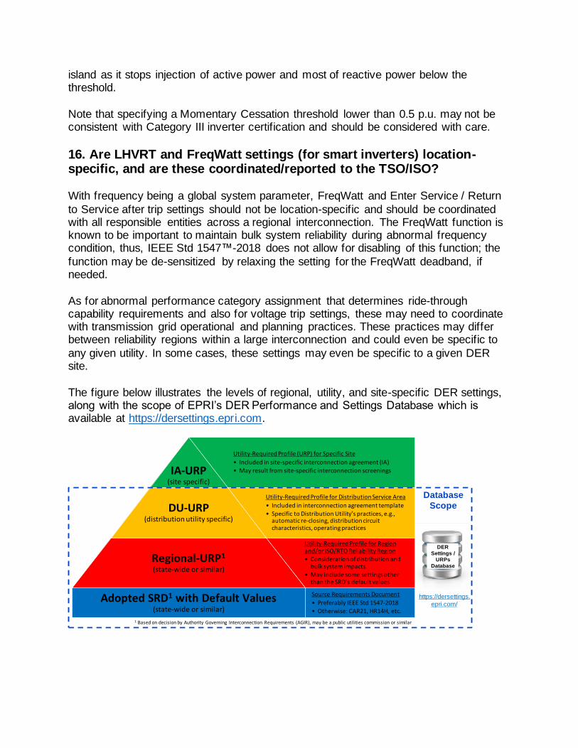
The figure below illustrates the levels of regional, utility, and site-specific DER settings, along with the scope of EPRI’s DER Performance and Settings Database which is available at https://dersettings.epri.com.
Utility-Required Profile for Region and/or ISO/RTO Reliability Region• Consideration of distribution and
bulk system impacts.• May include some settings other
than the SRD’s default values
Regional-URP1
(state-wide or similar)
Utility-Required Profile for Distribution Service Area
• Included in interconnection agreement template
• Specific to Distribution Utility’s practices, e.g., automatic re-closing, distribution circuit characteristics, operating practices
DU-URP(distribution utility specific)
Utility-Required Profile (URP) for Specific Site
• Included in site-specific interconnection agreement (IA)
• May result from site-specific interconnection screeningsIA-URP(site specific)
1 Based on decision by Authority Governing Interconnection Requirements (AGIR), may be a public utilities commission or similar
Adopted SRD1 with Default Values(state-wide or similar)
Source Requirements Document
• Preferably IEEE Std 1547-2018
• Otherwise: CAR21, HR14H, etc.
Database
Scope
DER
Settings /
URPs
Database
https://dersettings.
epri.com/

17. How are Category III ride-through assignments reconciled against anti-islanding clearing time?
They are mutually exclusive conditions. Ride-through (RT) requirements do not apply in
an island. Inverters’ on-board unintentional islanding detection methods can distinguish – in most cases – an islanded condition from a ride-through condition.
Section 4.7 Prioritization of DER responses in IEEE Std 1547™-2018 includes the following clause. “c) DER ride-through requirements specified in 6.4.2 and 6.5.2 shall take precedence over all other requirements within Clause 5 and Clause 6, with the exception of tripping requirements listed in item b) above. Ride-through may be
terminated by the detection of an unintentional island specified in 8.1. However, false detection of an unintentional island that does not actually exist shall not justify non-compliance with ride-through requirements. Conversely, ride-through requirements specified in Clause 6 shall not inhibit the islanding detection performance specified in
8.1 where a valid unintentional islanding condition exists.”
If distribution utilities do not trust inverters’ on-board unintentional islanding detection
(UID) methods to distinguish between ride-through and islanded condition, Category III performance capability assignment can be combined with short trip clearing times that are coherent with the 2 seconds UI clearing time. Where distribution utilities trust the on-board inverter UID methods to be reliable, Category III ride-through operation and
voltage trip clearing time settings longer than 2 seconds are not contradictory to the shorter 2 seconds UID clearing time. Where acceptable and desired, IEEE Std 1547™-2018 allows distribution utilities to extend the UID clearing time for up to 5 seconds.
18. How should IEEE Std 1547™-2018 Category I, II, III be established in context of interoperability with the TSO/ISO?
The table below shows a summary of the expected abnormal performance category assignment in the adoption of IEEE Std 1547™-2018 (after amendment) according to
the power conversion technology. This is broadly in line with the NERC Reliability Guideline Bulk Power System Reliability Perspectives on the Adoption of IEEE Std 1547™-2018 published in March 2020 (https://www.nerc.com/comm/PC_Reliability_Guidelines_DL/Guideline_IEEE_1547-
2018_BPS_Perspectives.pdf).

Power Conversion Prime Mover / Energy Source Category
Inverter
Solar PV, Battery Energy Storage Category III (previously Cat II prior to amendment)
Wind Category II
Hydrogen Fuel Cell Mutual Agreement
Synchronous generator
Bio-/landf ill gas, fossil fuel, hydro, combined heat & power
Category I
Induction generator Hydro Mutual Agreement
19. Are there quantifiable benefits to ride-through settings for
distribution systems? If so, at what penetration levels might these benefits start to be observed?
In most cases, the short answer is no – ride-through is of primary interest to the load balancing entity responsible for energy supply/demand, and distribution utilities tend to
prefer tripping of DER over ride-through for personal safety reasons. But there are emerging cases, such as intentional feeder-level islanding and other resiliency concepts, in which the distribution operator may prefer DER ride-through over trip, even for extended periods. Assigning Category III prepares DER to have capabilities in the
shorter term that could be utilized by DER trip settings reconfiguration in the longer term, as the distribution protection evolves.
20. Is there any risk of negative control interactions i.e. oscillations, between traditional voltage regulation equipment and between multiple smart inverters? If yes, what are the potential mitigations?
EPRI research on distribution system stability related to volt-var shows that there is a very low probability of oscillatory behavior for all but the weakest systems with fast
responding DER (short open-loop response time) and steep volt-var slopes. This is true for a single DER oscillating with the connected system, multiple DER oscillating with the system and between one another, and DER oscillating with discrete voltage regulating equipment. Applying very steep volt-var slopes or control gain on very weak systems
can result in undamped oscillations, but the default IEEE Std 1547™-2018 volt-var settings are generally very safe. In very weak systems, it is recommended that the DER be screened for stability. It should be noted that applying a steep slope may be desired to help mitigate voltage issues, so it is important to consider potential stability when
deviating from default settings.

21. Is there an effective way to study multiple inverters on the same feeder in time-series power flow with industry standard modeling
software tools?
Yes – most planning tools allow for time-series power flow analysis with advanced functions enabled for multiple DER on a feeder. It is recommended that the utilities build the in-house capabilities and data to perform this type of analysis.
22. Some research has indicated that the volt-var function provides the highest value to utilities. Is this the case, and therefore recommended,
that each utility should select the volt-var function across the entire grid as the default function? Or are more studies required i.e. on case-by
case interconnection basis?
This EPRI tech brief, Value of a Distribution Management System for Increasing Hosting
Capacity: Centralized vs. Autonomous Control of Distributed Energy Resources, 3002013386, Dec 2018, shows that the volt/var setting is critical. It is not a one setting fits all. The brief compares three methods on different feeders. As mentioned earlier, applying universal settings at all locations is easy to administer, but may not serve the
ultimate utility objectives. EPRI recommends that simulations be performed, where possible, to assess autonomous functions. When simulations cannot be performed and there are no existing or near-term voltage regulation issues, EPRI recommends utilities consider either DER self-mitigation functions (fixed power factor) or default volt-var.
Default volt-var may do “no harm”, but also may not contribute to mitigating future voltage issues unless the voltages are outside the deadband.
23. What are the differences in settings on protection relays and associated equipment when considering volt-var operation on
secondary meshed networked systems vs. radial systems?
Since mesh network systems must detect reverse power flow (flow from customer into
network) to maintain system reliability, the network protector settings must be tuned when DER is present. Some utilities with secondary mesh networks have developed adaptive network protector settings that allow for DER to operate on the network system. System overvoltage and overcurrent protection is a key consideration for radial
systems when including the ride-through capabilities outlined in IEEE Std 1547™-2018. Distribution protection engineers must be mindful of these new requirements and assure that their practices do not defeat the ride-though requirements for BES reliability. This requires a significant shift in thinking for distribution protection engineers.
24. Is it possible to develop default settings for volt-var management?
Applying universal default volt-var settings are inherently not “optimized” for all applications, and the DER will tend to either under- or over-compensate. Voltage
regulation functions on DER, particularly primary-connected DER, need to be

coordinated with the necessary system voltage profile in order to deliver satisfactory voltage levels elsewhere in the distribution system. For example, a DER using volt-var that is located downstream of and near to a mid-feeder regulator with default settings
will try to absorb reactive power to oppose the necessary elevated voltage at that location, thus defeating the overall feeder voltage management strategy. The reference voltage for that DER may need to be modified, or a different control mode used.
25. Can utilities instruct existing DER sites to change settings when another DER interconnects? Should utilities expect the need to change
inverter settings on existing DER on a feeder or substation when another DER interconnects?
See prior answer about site-specific settings vs. DERMS. It is likely that ideal settings will change as conditions change on the feeder. Site owners could be enlisted in making
such changes, but the conditions for doing this would need to be laid out in the interconnection agreement. EPRI would recommend that, if needed, utilities make these changes in coordination with plant owners.
26. It is understood that both volt-var and volt-watt functions are typically enabled simultaneously. How are they to be coordinated with
each other?
The two functions can be used separately, or together. They are not dependent on one another nor are they mutually exclusive. Use of the volt-watt function is not as common as volt-var. When used in conjunction, the common approach is to set volt-var to act in the normal ranges of voltage, then use volt-watt only to act to prevent overvoltage when
extremes have occurred (e.g. Voltage at or above 1.05Pu). Essentially, volt-watt is considered a “soft trip” that gradually reduces active power production to help reduce voltage that cannot be accomplished through the volt-var function, which also prevents tripping of the DER.
27. Do different manufacturers have different specifications for ramping?
Commercial inverters currently available in the market (and field) may have different
ramp rate specifications depending on manufacturers and models. IEEE Std 1547™-2018 does not specify any “normal ramp rate limit” other than the ones stated here. This is different from CA Rule 21 but was an intentional decision.
28. Should ramping be specified for smaller DERs?
There are many examples worldwide (a growing number) where high penetration DER issues are occurring from large numbers of small DER. Depending on the conditions in specific operating regions, this may or may not be a concern at this time.

Eventually, however, small DER operations may become a concern. For this reason, it is important to distinguish what is required in terms of “capability” from what is required to be activated. EPRI would advise that the full suite of ramping capabilities (including
random and fixed delays for Enter-Service) addressed in IEEE Std 1547™-2018 by a required capability of all DER sizes.
Limiting DER reconnection ramp up after disconnection due to a grid fault impacting large areas might be important to limit sudden excess generation into the system after the outage.
29. As DER penetration increases, how should a standard ramp rate be developed? Based on size? Concerns are with all coming on at once
after an outage of BESS charging, high or low voltage and operational issues with LTCs and regulators can occur. How do the impacts and
concerns differ for Reconnect on Restoration?
Section 4.10.3 (Performance during entering service) in IEEE Std 1547™-2018 includes the following exception for smaller DER systems: Exception 1: For Local EPS that have an aggregate DER rating of less than 500 kVA, individual DER units may increase output of active power with no limitation of the rate-of-change, following an additional
randomized time delay with a default maximum time random interval of 300 s, and with an adjustable range for the maximum time random interval of 1 s to 1000 s.
30. When DER is absorbing vars to reduce overvoltages, is there a concern related to additional reactive power demand that must be provided by a var source such as a capacitor bank?
When DER absorbs vars to mitigate overvoltage, the vars must be provided from either the distribution or transmission system. If var demand is a serious concern, then it must
be included in the overall objectives related to the application of advanced DER functions. Accurate assessment of var demand requires times series simulations, as the var demand is highly dependent upon DER output and system load. Operating at a fixed absorbing power factor may create var demand issues. For these situations, volt-var
with a deadband may help to lower reactive power demand. However, EPRI would recommend an analysis to fully evaluate each potential advanced function and setting impact on var demand.
31. Does the set active power mode require communications to implement?
The “Set active power mode” is a dispatch function (“go-to this power level”), whereas
the Limit Active Power is a constraint (“stay below this level”). Both functions can be driven locally, such as by a gateway or controller, for example, running a schedule of charge/discharge activity. However, more advanced utilization of this function for grid support will need communication with utility end control entities like DERMS. The set
active power function is currently not required in IEEE Std 1547™-2018. It could be integrated into either a future revision of IEEE 1547, or a potential new IEEE-SA project, for performance requirements of DER gateways located at the utility side of the local
communication interface of the DER.
32. Is the set active power function applicable to solar inverters, as
power output is dependent on solar irradiance and not a setting?
For solar inverters, this function will have effect only when available power is higher than the target power.
33. What is a good back-up plan if a remote control function doesn’t work as intended?
Failure to perform could occur on many levels, including unforeseen characteristics in the original designs and/or becoming unprogrammed/unconfigured over time. EPRI is
presently working with members to address these concerns in four primary ways:
• Comprehensive DER testing and characterization that explores corner-case
behaviors not-specified by IEEE Std 1547™-2018 and not tested by UL. • Interconnection guidelines that limit the impact of individual DER non-
performance • Data analytics that can run on regular AMI data and detect non-performing DERs
• Software tools that utilities can use to independently check the configuration and performance of suspected non-performing DERs
34. What use cases could exist for Set Active Power Mode in the short
term? Long term?
IEEE Std 1547™-2018 section 4.6.2 defines “limit active power”, not “set active power”. Limit active power requires DER to limit its active power output to not greater than the active power limit set point. In near term, limit active power mode can be used to limit grid export in certain conditions where excess generation may violate voltage or thermal
limits. In the long term, this control mode may enable flexible interconnection.
35. Are there available use cases for the dynamic reactive current
support setting?
This function is covered in CA R21, but is not specified in IEEE Std 1547™-2018. “Dynamic reactive current support” is sometimes confused with “dynamic reactive support”, which would be the use of the volt-var function as specified in IEEE Std 1547™-2018 clause 5.3.3 (Voltage-reactive power mode), but with a fast response, i.e.,
a smaller than default setting for the open loop response time. The answer below refers

to “dynamic voltage support” as defined in IEEE Std 1547™-2018 clause 6.4.2.6 (Dynamic voltage support) which is not a required nor specified function; it is only allowed and was intentionally not specified in detail in the standard and related test
procedures.
IEEE Std 1547™-2018 section 6.4.2.6 footnote 90 includes the following text: “Dynamic
voltage support provides rapid reactive power exchanges during voltage excursions. Dynamic voltage support may provide better voltage stability in the distribution system during transient events extending into voltage ride-through or high-voltage ride-through regions.”
The dynamic reactive current support function is defined in Chapter 18 of the following EPRI report: Common Functions for Smart Inverters: 4th Edition. EPRI, Palo Alto, CA:
2016. 3002008217.
At this point, it is recommended not to require this function, as it has not been
standardized and certified equipment is not expected to become available any time soon. The function can also potentially have negative impacts on distribution protection coordination. It is expected, though, to provide bulk power system benefits. The IEEE 1547.2 Application Guide will provide further information on the potential benefits and
challenges of this function.
36. How will the utility be able to send Q commands to inverters, or does
this function only operate locally i.e. through local PQ monitoring at POI?
Dynamic Reactive Current Support is an autonomous function. Like the volt-var function, the characteristic curve of this function can be configured and/or changed.
However, reactive current changes autonomously in response to the rate of change of voltage. “Dynamic reactive current support” is sometimes confused with “dynamic reactive support” which would be the use of the volt-var function as specified in IEEE Std 1547™-2018 clause 5.3.3 (Voltage-reactive power mode), but with a fast response,
i.e., a smaller than default setting for the open loop response time. If the question refers to “dynamic voltage support” as defined in IEEE Std 1547™-2018 clause 6.4.2.6 (Dynamic voltage support), it is recommended not to require this function.
37. What kW level of smart inverters are typically monitored, and what is the technology applied that is cost effective?
It is good to separately consider (a) capability to be monitored (a requirement of the DER) and (b) subsequent decisions to deploy a communication system and make use
of the monitoring capability. Section 10.5 in IEEE Std 1547™-2018 requires that the DER shall be capable of providing monitoring information through a local DER communication interface and shall include the information listed in Table 29. IEEE Std 1547™-2018 requirements are applicable to all DERs, irrespective of size and type.
This capability is just now being mandated and existing DER use proprietary protocols and cannot be practically monitored through direct communication. Utilities that are “monitoring” DER presently are typically doing so through separate meters (basic
revenue meters or advanced PQ meters, depending on the situation). While this approach produces more accurate data, the cost limits the size to which it is practical, typically to 100kW or larger.
Going forward however, the IEEE Std 1547™-2018 monitoring capability requires only a communication connection to the DER. EPRI’s cost analysis for connectivity considers four main elements: equipment cost, install cost, data/ongoing charges, and
maintenance/longevity. Some technologies, such as utility Wi-Sun mesh AMI systems are very low in cost, with relatively maintenance-free operation, long life, leveraging existing infrastructure (e.g. access points, routers), low nodal cost and no data charge.
38. Are there any Cybersecurity considerations related to communication with DER?
There are security considerations for any scenario in which a communication system
connects to DER, regardless of the function(s) for which the communication is being used. For example, a cellular communication system might be deployed for monitoring-only purposes, but since the DER fundamentally have all the IEEE Std 1547™-2018 control capabilities, if the system were hacked, control actions could be taken.
The risks associated with hacking a single DER are much lower than if many DER would be compromised at the same time. Given that the scope of IEEE Std 1547™-
2018 is limited to requirements for single DER units and sites, and it does not specify any requirements for “aggregations of DER”, the standard intentionally stayed away from specifying cyber security requirements in its 2018 revision.
To address the greater risk of a compromised communication system that controls a large aggregation of DER, the key element to secure communication integration is the DER gateway device, indicated by red boxes in the below figure. This piece of hardware
is typically placed at the DER site and integrates any given DER into the utility (or other aggregating entity) communication network. Even though the DER itself is not trusted - being of unknown brand, of unknown origins, not owned/accessible, and not firmware upgradeable/patchable by the utility (or other aggregating entity) – a properly secured
DER gateway can prevent or mitigate cyber security breaches that would otherwise affect many DER sites and potentially impact the reliability of the bulk power system.

The P1547.3 Working Group is currently developing guidelines for Cybersecurity of
Distributed Energy Resources (DER) interconnection with Electric Power Systems (EPS). These guidelines may potentially be elevated to requirements in future revisions of IEEE 1547, or become recommended practices in a potential new IEEE-SA project for performance and cyber security requirements of DER gateways located at the utility
side of the local communication interface of the DER.
39. Is real-time or near real-time monitoring considered something that
will be necessary on all DERs, or only those above a certain size?
Many small DER aggregated can have similar impact on the grid as one large one, and there are examples worldwide where this has occurred, including Hawaii. As noted previously, the cost of monitoring is dropping with the recent direct communication capability specified by IEEE Std 1547™-2018. At the same time, utility metering
systems are increasing in performance, with additional quantities being measured, interval sizes shrinking and data transmission becoming more frequent (closer to real-time). As this occurs, it is possible that the utility’s needs for visibility to small DER can be satisfied in the near term. From a strategy/roadmap perspective, it is anticipated that
all will become connected eventually.
40. Are there any use cases for DER disconnect and reconnect? What
size does the industry think this action is needed through SCADA communication?
Utilizing inverter disconnect and reconnect capability can potentially eliminate the need for external switch along with relay and/or DTT receiver. The timing of operation and
reliability of communications becomes a critical consideration when considering this option. MW and larger-sized systems should be considered for SCADA communication.

41. Can the limit max active power mode be autonomous and not require active communications?
Yes, this function can be autonomous, either in the form of a fixed setting in the DER or
by following a fixed recurring schedule in a local DER gateway. A local active power limit may also be used in non-export or limited-export DER interconnection of solar PV+storage applications. Communication from central control systems expands the potential uses, allowing power to be limited due to needs/constraints that were not
predictable or occurred elsewhere on the system.
42. Does this function require communications or can localized settings
be used i.e. at X time of day/month, or local system conditions result in a change from 100% to 50% active power limit?
Volt-watt is an example of limiting max active power, depending on local voltage conditions. Note that local scheduled capability as mentioned in the question is not a
capability of the DER itself, but would be supported by an autonomous utility controller, placed at the site and controlling the DER via the IEEE Std 1547™-2018 communication port.
43. Does the inverter support pre-programmed schedule-based power output settings? Or is a plant controller required in conjunction with the
smart inverter?
IEEE Std 1547™-2018 does not require DER to have scheduling capability of any kind.
Individual vendors may add scheduling features in their products, but because this is done in a non-standardized way, and is not tested, it is not generally of use to utilities. Industry trends and offerings appear to indicate most current commercial inverters do not support scheduling.
The term “plant controller” may refer to a component of the DER plant – an element used by the plant designer to coordinate across multiple inverters, etc. In these cases,
the plant controller is included in the IEEE Std 1547™-2018 definition of a “DER” and still does not present a useful scheduling capability to the utility. A “gateway” (also called a Network Adapter/Module in IEEE Std 1547™-2018 Figure 4) is part of the integration system for DERs and can be designed to operate locally without an of fsite
communication system and provide autonomous DER scheduling capability.
44. What is the utility back-up plan if one of the remote smart inverter
functions doesn’t work as intended to resolve a distribution system issue?
Failure to perform could occur on many levels, including unforeseen characteristics in the original designs and/or becoming unprogrammed/unconfigured over time. EPRI is
presently working with members to address these concerns in four primary ways:

• Comprehensive DER testing and characterization that explores corner-case behaviors not-specified by IEEE Std 1547™-2018 and not tested by UL.
• Interconnection guidelines that limit the impact of individual DER non-
performance • Data analytics that can run on regular AMI data and detect non-performing DERs • Software tools that utilities can use to independently check the configuration and
performance of suspected non-performing DERs
45. How is the scheduling power value function applied, and are there
any use cases/examples?
Several energy storage (ES) and PV plus ES system use cases can benefit from being scheduled. Examples may include limiting grid export at certain time windows, solar generation time shifting (solar charging in the morning and discharging during evening load peak hours), and solar firming.


