Embed Size (px)
Citation preview
XJFRotary Screw Compressor
Models XJF 95, 120, 151
This manual contains installation, operation, and maintenance instructions. Read thoroughly before beginning installation. Failure to follow these instructions may result in personal injury or death,
damage to the unit, or incorrect operation.
Form 070.450-IOM (NOV 2013) Installation – Operation – MaintenanceFile: Service Manual – Section 070Replaces: NothingDistribution: 3, 3a, 3b, 3cRevised: March 16, 2022
Check www.FrickCold.com for the latest version of this publication.
070.450-IOM (NOV 13)Page 2
XJF Rotary Screw CompressorInstallation - Operation - Maintenance
Table of Contents
General informationPreface ............................................................................. 3Design limitations ............................................................. 3Job inspection .................................................................. 3Standard bare compressor ............................................... 3Transit damage claims ...................................................... 3Compressor identification ................................................ 3Long term storage ............................................................. 4
Preparing compressor for storage ................................ 5Maintaining compressor ............................................... 5
Description ........................................................................ 5XJF compressor ........................................................... 5Compressor lubrication system ................................... 5Oil pump ....................................................................... 5
Construction details .......................................................... 6
InstallationDesign limits ..................................................................... 7Outline dimensions ........................................................... 7SAE straight thread o-ring fittings -
assembly procedure for RXF 58 - 101 ..................... 14Holding charge and storage ............................................ 14Rigging and handling ....................................................... 15
Lifting instructions ..................................................... 15Foundation ..................................................................... 15Customer connections .................................................... 16Compressor oil ................................................................ 16Oil pump ......................................................................... 16Compressor ..................................................................... 16
Mounting .................................................................... 16Compressor/motor coupling requirements. ................ 16Coupling alignment requirements (foot mounted only) .................................................... 17
Oil heater(s) ................................................................... 17Oil filter(s) ...................................................................... 17Oil cooling requirements ................................................. 17Economizer - high stage ................................................. 17Liquid injection oil cooling ............................................... 18Dehydration / evacuation test ......................................... 19Electrical installation ....................................................... 19
Capacity slide valve transmitter .................................. 19Compressor hydraulic system.......................................... 20Low-ambient operation ................................................. 21
OperationOperation and start-up instructions ............................... 23Initial start-up ................................................................ 23
Initial start-up procedure .......................................... 23Normal start-up procedure ........................................ 23
MaintenanceGeneral information ....................................................... 23Normal maintenance operations .................................... 23
General maintenance ................................................ 24Maintenance schedule ..................................................... 24
Changing oil ............................................................... 25Recommended maintenance program ....................... 25
Vibration analysis ........................................................... 25Oil quality and analysis ................................................... 25
Operating log ............................................................ 25Maintenance schedule ............................................... 25
Troubleshooting guide .................................................... 25Abnormal operation analysis and correction ............. 25
Slide valve transmitter replacement ................................ 26Bare compressor mounting ............................................. 26Troubleshooting the compressor ..................................... 26Troubleshooting the hydraulic system ............................. 27P and I drawings.............................................................. 28Rotary screw compressor operating log sheet ................ 32Forms .............................................................................. 32Read this first: compressor prestart checklist ................. 33Vibration data sheet ........................................................ 35
Indicates an imminently hazardous situation which, if not avoided, will result in death or serious injury.Indicates a potentially hazardous situation or practice which, if not avoided, will result in death or serious injury.
Safety precaution definitions
Indicates a potentially hazardous situation or practice which, if not avoided, will result in damage to equipment and/or minor injury.
Indicates an operating procedure, practice, etc., or portion thereof which is essential to highlight.
WARNING
CAUTION
DANGER
NOTICE
070.450-IOM (NOV 13)Page 3
XJF Rotary Screw CompressorInstallation - Operation - Maintenance
Note: The information contained in this document is sub-ject to change without notice
General information
Preface This manual has been prepared to acquaint the owner and serviceman with the installation, operation, and mainte-nance procedures as recommended by Johnson Controls-Frick® for XJF Rotary Screw Compressors.
It is most important that these compressors be properly ap-plied to an adequately controlled refrigerant or gas system. Your authorized Johnson Controls-Frick representative should be consulted for their expert guidance in this deter-mination.
Proper performance and continued satisfaction with these units is dependent upon:
• Correct installation • Proper operation • Regular, systematic maintenance
To ensure correct installation and application, the equip-ment must be properly selected and connected to a prop-erly designed and installed system. The Engineering plans, piping layouts, etc. must be detailed in accordance with the best practices and local codes, such as those outlined in ASHRAE literature.
A screw compressor is a vapor pump. To be certain that it is not being subjected to pumping liquid, it is necessary that controls are carefully selected and in good operat-ing condition; the piping is properly sized and traps, if necessary, are correctly arranged; the suction line has an accumulator or slugging protection; that load surges are known and provisions are made for control; operating cycles and stand still periods are reasonable; and that high side components are sized within system and compressor design limits.
NOTICEIt is required that the discharge temperature be kept high enough to prevent condensation of any moisture in the compressor and oil separator.
Design limitations XJF compressors are designed for operation within the pressure and temperature limits that are specified by Johnson Controls-Frick and the Johnson Controls-Frick se-lection software COOLWARE™. They are primarily used for compressing refrigerant gas and most hydrocarbon gasses.
If your application is for sour gas, there are special require-ments to protect the compressor. Contact Johnson Controls - Frick Compressor Engineering for application details.
Job inspection Immediately upon delivery examine all crates, boxes and exposed compressor and component surfaces for damage. Unpack all items and check against shipping lists for any discrepancy. Examine all items for damage in transit.
Standard bare compressor Items not included with bare compressor that are avail-able as sales order options: Motor Mount, Solenoid Valve Capacity, Tank Drain Tubing (T connection), Oil Feed Line (P connection), Connection Fittings, Coupling.
Transit damage claims All claims must be made by the consignee. This is an ICC requirement. Request immediate inspection by the agent of the carrier and be sure the proper claim forms are ex-ecuted. Report damage or shortage claims immediately to Johnson Controls-Frick Sales Administration Department, in Waynesboro, PA.
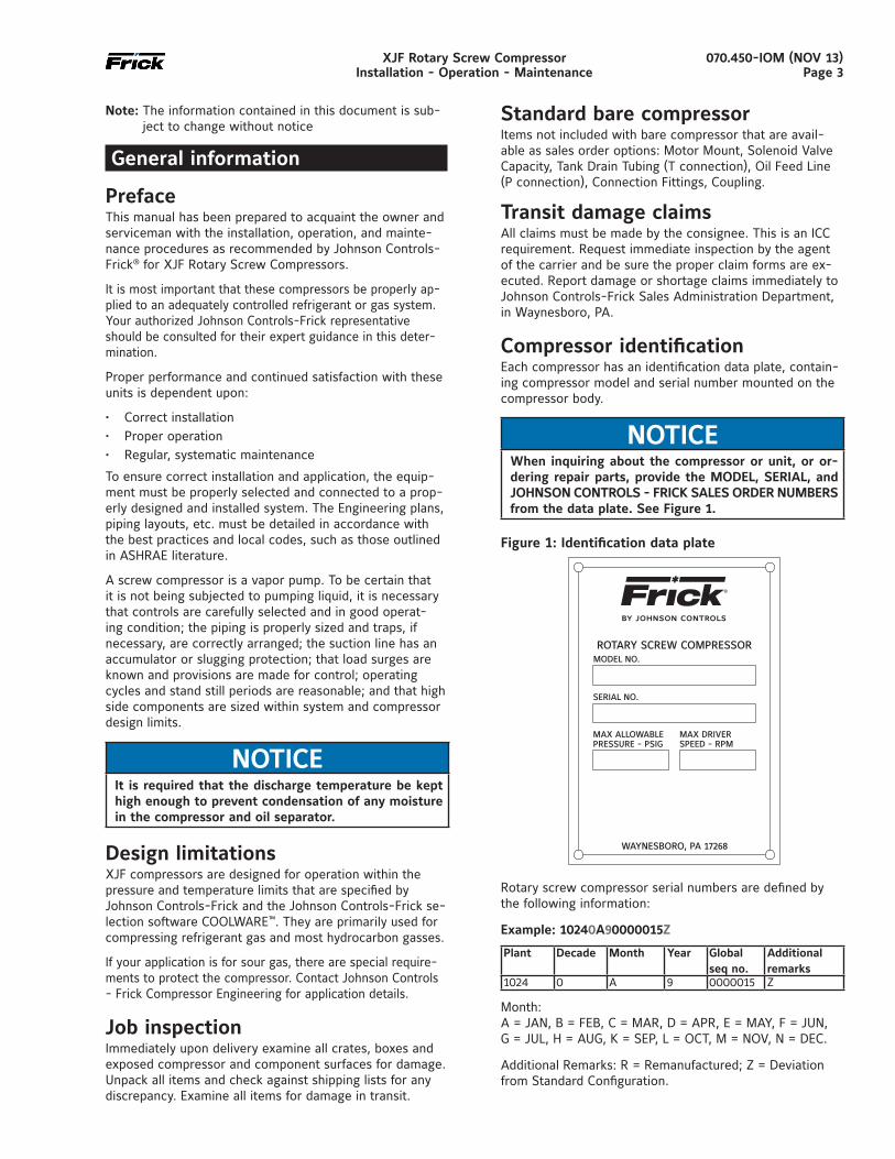
Compressor identification Each compressor has an identification data plate, contain-ing compressor model and serial number mounted on the compressor body.
NOTICEWhen inquiring about the compressor or unit, or or-dering repair parts, provide the MODEL, SERIAL, and JOHNSON CONTROLS - FRICK SALES ORDER NUMBERS from the data plate. See Figure 1.
Figure 1: Identification data plate
Rotary screw compressor serial numbers are defined by the following information:
Example: 10240A90000015Z
Plant Decade Month Year Globalseq no.
Additionalremarks
1024 0 A 9 0000015 Z
Month: A = JAN, B = FEB, C = MAR, D = APR, E = MAY, F = JUN, G = JUL, H = AUG, K = SEP, L = OCT, M = NOV, N = DEC.
Additional Remarks: R = Remanufactured; Z = Deviation from Standard Configuration.
070.450-IOM (NOV 13)Page 4
XJF Rotary Screw CompressorInstallation - Operation - Maintenance
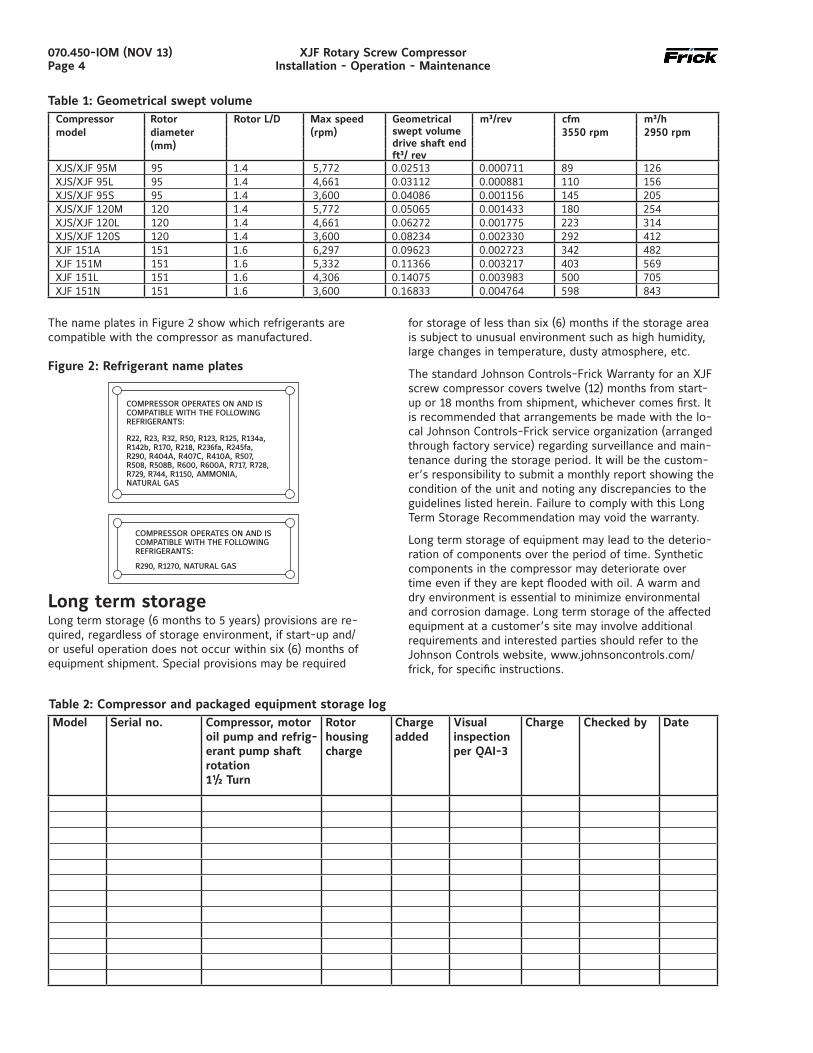
The name plates in Figure 2 show which refrigerants are compatible with the compressor as manufactured.
Figure 2: Refrigerant name plates
Long term storageLong term storage (6 months to 5 years) provisions are re-quired, regardless of storage environment, if start-up and/or useful operation does not occur within six (6) months of equipment shipment. Special provisions may be required
for storage of less than six (6) months if the storage area is subject to unusual environment such as high humidity, large changes in temperature, dusty atmosphere, etc.
The standard Johnson Controls-Frick Warranty for an XJF screw compressor covers twelve (12) months from start-up or 18 months from shipment, whichever comes first. It is recommended that arrangements be made with the lo-cal Johnson Controls-Frick service organization (arranged through factory service) regarding surveillance and main-tenance during the storage period. It will be the custom-er’s responsibility to submit a monthly report showing the condition of the unit and noting any discrepancies to the guidelines listed herein. Failure to comply with this Long Term Storage Recommendation may void the warranty.
Long term storage of equipment may lead to the deterio-ration of components over the period of time. Synthetic components in the compressor may deteriorate over time even if they are kept flooded with oil. A warm and dry environment is essential to minimize environmental and corrosion damage. Long term storage of the affected equipment at a customer’s site may involve additional requirements and interested parties should refer to the Johnson Controls website, www.johnsoncontrols.com/frick, for specific instructions.
Table 2: Compressor and packaged equipment storage logModel Serial no. Compressor, motor
oil pump and refrig-erant pump shaft rotation 1½ Turn
Rotor housing charge
Charge added
Visual inspection per QAI-3
Charge Checked by Date
Compressor model
Rotor diameter (mm)
Rotor L/D Max speed (rpm)
Geometrical m³/rev cfm 3550 rpm
m³/h 2950 rpmswept volume
drive shaft endft³/ rev
XJS/XJF 95M 95 1.4 5,772 0.02513 0.000711 89 126XJS/XJF 95L 95 1.4 4,661 0.03112 0.000881 110 156XJS/XJF 95S 95 1.4 3,600 0.04086 0.001156 145 205XJS/XJF 120M 120 1.4 5,772 0.05065 0.001433 180 254XJS/XJF 120L 120 1.4 4,661 0.06272 0.001775 223 314XJS/XJF 120S 120 1.4 3,600 0.08234 0.002330 292 412XJF 151A 151 1.6 6,297 0.09623 0.002723 342 482XJF 151M 151 1.6 5,332 0.11366 0.003217 403 569XJF 151L 151 1.6 4,306 0.14075 0.003983 500 705XJF 151N 151 1.6 3,600 0.16833 0.004764 598 843
Table 1: Geometrical swept volume
070.450-IOM (NOV 13)Page 5
XJF Rotary Screw CompressorInstallation - Operation - Maintenance
The following guidelines must be followed to maintain the screw compressor warranty.
Preparing the compressor for storage1. Evacuate the compressor to remove moisture.
2. Connect the evacuation lines to the three Schrader ac-cess valves provided with the compressor. One valve is connected to the compressor suction and the other two valves are located at the block on the cylinder.
3. Break the vacuum with dry nitrogen and bring pressure to 0 psig
4. Pump oil into the SM1. Use break-in oil P/N 111Q0831809 for storage purposes. The amounts of oil needed per compressor are:
• 95 mm - 2 gal• 120 mm - 3 gal• 151 mm - 8 gal5. After compressor is oil charged, pressurize compressor to 15 psig with nitrogen.
Maintaining the compressor1. Maintain the 5 psig to 15 psig nitrogen charge, but ide-ally at 15 psig.
2. Rotate the male rotor shaft every two weeks. Mark the shaft to ensure the rotor does not return to the original position..
3. Store the compressor inside a dry building environment.
4. Grease the male rotor shaft to prevent rust.
5. Record all information in a compressor long-term storage log. See Table 2.
Contact Johnson Controls-Frick Service with any ques-tions regarding long term storage.
DescriptionXJF compressor The Frick XJF rotary screw compressor utilizes mating asymmetrical profile helical rotors to provide a continuous flow of vapor and is designed for both high-pressure and low-pressure applications. The compressor incorporates the following features:
1. High-capacity roller bearings to carry radial loads at both the inlet and outlet ends of the compressor. 2. Heavy-duty angular contact ball bearings to carry axial loads are mounted at the discharge end of compressor.3. Moveable slide valve to provide fully modulating capac-ity control from 100% to 25% of full load capacity. 4. VOLUMIZER II volume ratio control adjusts the compres-sor volume ratio during operation to the most efficient of three possible volume ratios, 2.2, 3.5, 5.0, depending upon system requirements.5. A hydraulic cylinder to operate the slide stop and slide valve. 6. Compressor housing suitable for 400 psig pressure.
7. Most bearing and control oil is vented to closed threads in the compressor instead of suction port to avoid perfor-mance penalties from superheating suction gas.8. The shaft seal is designed to maintain operating pressure on the seal well below discharge pressure for increased seal life.9. Oil is injected into the rotor threads to maintain good volumetric and adiabatic efficiency, even at high compres-sion ratios.10. Shaft rotation clockwise facing compressor, suitable for all types of drives. SEE FOLLOWING WARNING.
WARNINGIt is mandatory that the coupling center be removed and the direction of motor rotation be confirmed be-fore running the compressor. Proper rotation of the compressor shaft is clockwise looking at the end of the compressor shaft. Failure to follow this step could result in backward compressor rotation which can cause compressor failure or explosion of the suction housing.
Compressor lubrication system
The XJF compressor is designed specifically for operation without an oil pump for high stage service. Boosters and some low-differential pressure appli cations will require the pump option.
The lubrication system on an XJF equipped screw com-pressor unit performs several functions:
1. Lubricates the rotor contact area, allowing the male ro-tor to drive the female rotor on a cushioning film of oil.
2. Provides lubrication of the bear ings and shaft seal.
3. Serves to remove the heat of compression from the gas, keeping discharge temperatures low and minimizing refriger ant or oil break down.
4. Fills gas leakage paths between or around the rotors with oil, thus greatly reducing gas leakage and main tain ing good compressor per formance even at high compres sion ratios.
5. Provides oil pressure for development of balance load on the balance pistons to reduce bearing loading and increase bearing life.
Oil pump
The XJF screw compressor unit is designed to be self-lu-bricating. Oil being supplied to the compres sor from the oil separator is at system head pressure. Within the compressor, oil porting to all parts of the compressor is vented back to a point in the compres sor’s body that is at a pressure lower than compressor discharge pressure. The compressor’s normal operation makes the compressor unit operate essentially as its own oil pump. All oil entering the compressor is moved by the compressor rotors out the compressor outlet and back to the oil separator. For normal high-stage operation an oil pump is not required.
070.450-IOM (NOV 13)Page 6
XJF Rotary Screw CompressorInstallation - Operation - Maintenance
Construction detailsHousing: All XJF screw compressor castings are close grain, pressure tight, grey cast iron, to ensure structural, mechanical, and thermal stability under all operating con-ditions. Ductile iron is also available for special applica-tions. Contact Johnson Controls–Frick Sales for additional information.
Rotors: The rotors are made from the highest quality rolled steel to exacting tolerances of the latest industry standard asymmetric profile. The five-lobed male rotor is directly connected to the internal gear. The seven-lobed female rotor is driven by the male on a thin oil film.
Gear: The compressor has an internal gear to speed up the rotors. Each model has 3 or 4 gear ratios.
Bearings: Antifriction bearings with L10 rated life in excess of 50,000 hours (using the Frick Superfilter™) at design conditions are used for reduced frictional horse-power and superior rotor positioning, resulting in reduced power consumption, particularly at higher pressure ratios. Cylindrical roller bearings are provided to handle the ra-dial loads and the thrust loads are absorbed by four point contact or angular contact bearings. In addition, thrust balance pistons are provided to reduce the thrust load and improve bearing life.
Shaft seal: The compressor shaft seal is a single-face type with a spring-loaded carbon stationary surface riding against a cast iron rotating seat. The seal is capable of withstanding static pressure up to 400 psig. During opera-tion it is vented to low pressure to provide extended life.
Volumizer II adjustable volume ratio control: The Frick XJF compressor adjusts to the most efficient of three volume ratios (2.2, 3.5 or 5.0) depending upon system requirements. Control of the internal volume ratio elimi-
nates the power penalty associated with over- or under-compression. Volume ratio control is achieved by the use of a slide stop which is a movable portion of the rotor housing that moves axially with the rotors to control discharge port location. The slide stop is moved by hydraulic actuation of a control piston.
Stepless capacity control: Capacity control is achieved by use of a movable slide valve. The slide valve moves axially under the rotors to provide fully modulated capacity control from 100% to 25% of full load capacity.
The slide valve is positioned by hydraulic movement of its control piston. When in the unloaded position, gas is by-passed back to suction through a recirculation slot before compression begins and any work is expended, providing the most efficient unloading method available for part-load operation of a screw compressor.
Motor mount: The XJF series is designed with a drive end flange that mates with a cast iron motor mount (available as a sales order option). The motor mount is precision machined so that it ensures proper alignment of the com-pressor and motor coupling.
070.450-IOM (NOV 13)Page 7
XJF Rotary Screw CompressorInstallation
Installation
Design limitsGeneral information for all of the models is provided be-low. Please see CoolWare to determine the limits for a specific application.
XJF compressors are primarily designed for connecting to an electric drive motor using a tunnel mount. If the appli-cation requires it, the compressor can also be driven with a foot-mounted motor. The tunnel mount ensures proper alignment of the compressor and motor so that the shaft seal and coupling will operate properly. The rotor and bearing design set limitations must not be exceeded (See Frick Selection Program, CoolWare). Pressure and tem-perature limits are shown in Frick publication 070.410-SED. Refer to Johnson Controls-Frick Compressor Control Panel instruction 090.040-O for additional information on setpoint limits.
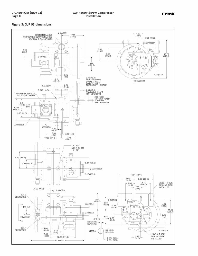
Outline dimensionsDrawings for reference only can be found on the following pages. Complete dimensions and access connections can be found on the outline drawings.
XJF 95 DWG# 534E0458
XJF 120 DWG# 534E0299
XJF 151 DWG# 534E0539
If you do not have these drawings, please request any you require by contacting Johnson Controls-Frick sales.
The notes below apply to the Dimensions and Com-pressor Port Location drawings on the following pages.
1. A metric rectangular parallel key is supplied with each XJF 95 and 120 compressor. Metric key conforms to din 6885A specification. A standard square parallel key is supplied with each XJF 151 compressor.
2. Standard voltage for solenoid coils is 110 VAC unless otherwise specified. Other voltages are available upon request.
3. Rotation of compressor jackshaft is clockwise when viewing the shaft end.
4. Solenoid control valves for Volume Ratio Slide Stop (SS) are included in delivery, including solenoids.
Solenoid control valves for Capacity Control Slide Valve (SV) are NOT included in delivery. Internal piping is included. A solenoid control valve kit with gasket can be ordered or specified separately on the sales order. The solenoid valve is a standard type D03/CETOP with O-rings suitable for application (either HNBR or Viton)
5. Motor support is not provided as part of the bare compressor. When required a motor support kit shall be specified on the sales order separately.
Approximate mass:
XJF 95: 600 lbm (272 kg)
XJF 120: 845 lbm (383 kg)
XJF 151: 1210 lbm (550 kg)
070.450-IOM (NOV 13)Page 8
XJF Rotary Screw CompressorInstallation
Figure 3: XJF 95 dimensions
2.13 (54)
CLDRIVE SHAFT
CL COMPRESSOR
5.21 (132.3)
5.27 (133.8)
4.34 (110.4)
8.13 (206.4)
8.25(209.6)
25.63 (651.1)
2.66 (67.6)
5.12(130)
12.25 (311.1)
6.06(153.9)
4.00(101.6)
6.84(173.9)
2.06(52.3)
3.13(79.5)
11.62(295.1)
2.75(69.9)
4.81(122.2)
CL SUCTION
8.13(206.6)
9.38 (238.3)
16.81 (427.1)
SOL-4SEE NOTE 3
SOL-3SEE NOTE 3
6.38(162.1)
3.50(88.9)
3.19 (81)
4.06(103.1)
6.56(166.6)
1.56 (39.6)
6.18(157)
.3937 (10.000)
.3951 (10.035)
Ø1.3781 (35.004)Ø1.3785 (35.014)
1.174 (29.82)1.182 (30.02)
LIFTINGM20 X 2.5-6H1.31 DP
2.00 (50.8)
1.71 (43.4)
1.20 (30.4)
.25 (6.4) THICKSEALING DISKINSTALLED
.25 ( THICKSEALING DISKINSTALLED
6.4)
OUT
OUT
TOP
4 3
10
A
A
VIEW A-A
CL ROTORS
10.69 (271.5 )
3.75 (95.3)
COMPRESSOR
7.56(192)
6.94(176.3 )
2.00 (50.8)MIN DIST REQ'DFOR SHAFTSEAL REMOVAL
1.94 (49.3)AVAILABLE SHAFTFOR COUPLING
CLDISCHARGE
DISCHARGE FLANGE2½" SOCKET WELD
10.88(276.3)
CL SUCTIONSUCTION FLANGE
FABRICATED SQUARE FLANGE2½" (95S & 95M), 3" (95L)
6.94(176.2)
8.45(214.5)
2.50 (63.5)
4.82(122.4)
CL DRIVE SHAFT
CL COMPRESSOR
18.75(476.3)
6.84(173.9)
2.72(69)
( )2.8171.42.43 (61.7)
0.94(23.9)
5.19(131.8)
2.56(65)
5.31(134.9)
1.85(46.9)
0.50 (12.7 )
0.75 (19.1)SEAL WEEPAGEDRAIN TUBETO BE PULLEDTHROUGH THIS HOLE
Ø.719 (18.3)
10.62(269.7)
3.66 (92.9)
CL
070.450-IOM (NOV 13)Page 9
XJF Rotary Screw CompressorInstallation
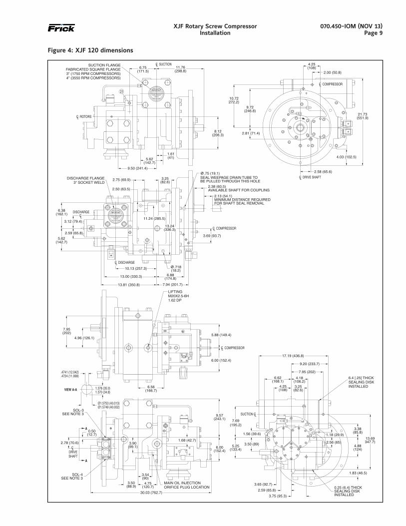
Figure 4: XJF 120 dimensions
CL COMPRESSOR
5.88 (149.4)
6.00 (152.4)
4.96 (126.1)
7.95(202)
6.56(166.7)
2.78 (70.6)
0.50(12.7)
9.57(243.1)
30.03 (762.7)
1.68 (42.7)3.90
(99.1)
3.54(90)
4.75(120.7)
6.62(168.1)
4.25(108)
5.25(133.4)
1.56 (39.6)
3.50 (89)
2.59 (65.8)
3.65 (92.7)
3.75 (95.3)
13.69347.7)
3.38(85.8)
4.88(124)
1.18 (29.9)
2.56 (65)
1.83 (46.5)
SUCTION CL
7.95 (202)
9.20 (233.7)
17.19 (436.8)
SOL-4SEE NOTE 3
SOL-3SEE NOTE 3
3.50(88.9)
7.69(195.2)
3.25(82.6)
MAIN OIL INJECTIONORIFICE PLUG LOCATION 0.25 (6.4) THICK
SEALING DISKINSTALLED
4.18(106.2)
6.00(152.4)
6.4 [.25] THICKSEALING DISKINSTALLED
LIFTINGM20X2.5-6H1.62 DP
OUT
OUT
TOP
34
A
A
13.00 (330.3)
13.81 (350.8) 7.94 (201.7)
2.59 (65.8)
3.12 (79.4)
6.38(162.1) DISCHARGE
CL
10.13 (257.3)
6.88(174.8)
11.24 (285.5)
3.69 (93.7)
13.24(336.3)
2.13 (54.1)MINIMUM DISTANCE REQUIREDFOR SHAFT SEAL REMOVAL
2.38 (60.5)AVAILABLE SHAFT FOR COUPLING
CL COMPRESSOR
CL DISCHARGE
DISCHARGE FLANGE3" SOCKET WELD
3.25(82.6)
2.75 (69.9)
∅.718(18.2)
∅.75 (19.1)SEAL WEEPAGE DRAIN TUBE TOBE PULLED THROUGH THIS HOLE
5.62(142.7)
2.50 (63.5)
SUCTION FLANGE BEFORE
IMPORTANT
PUTTING PACKAGE IN
REMOVE SEALING DISC FROM
OPERATION.
CL ROTORS
21
11.76(298.8)
CL SUCTION6.75
(171.5)
SUCTION FLANGEFABRICATED SQUARE FLANGE3" (1750 RPM COMPRESSORS)4" (3550 RPM COMPRESSORS)
9.72(246.8)
2.81 (71.4)
10.72272.2)
2.58 (65.6)
2.00 (50.8)
4.25(108)
CL DRIVE SHAFT
CL COMPRESSOR
21.73(551.9)
8.12(206.3)
1.61(41)5.62
(142.7)
9.50 (241.4)
4.03 (102.5)
SUCTION FLANGE BEFORE
IMPORTANT
PUTTING PACKAGE IN
REMOVE SEALING DISC FROM
OPERATION.
.4724 (11.999)
.4741 (12.042)
Ø1.5749 (40.002)Ø1.5753 (40.013)
1.370 (34.8)1.378 (35.0)VIEW A-A
CLDRIVESHAFT
070.450-IOM (NOV 13)Page 10
XJF Rotary Screw CompressorInstallation
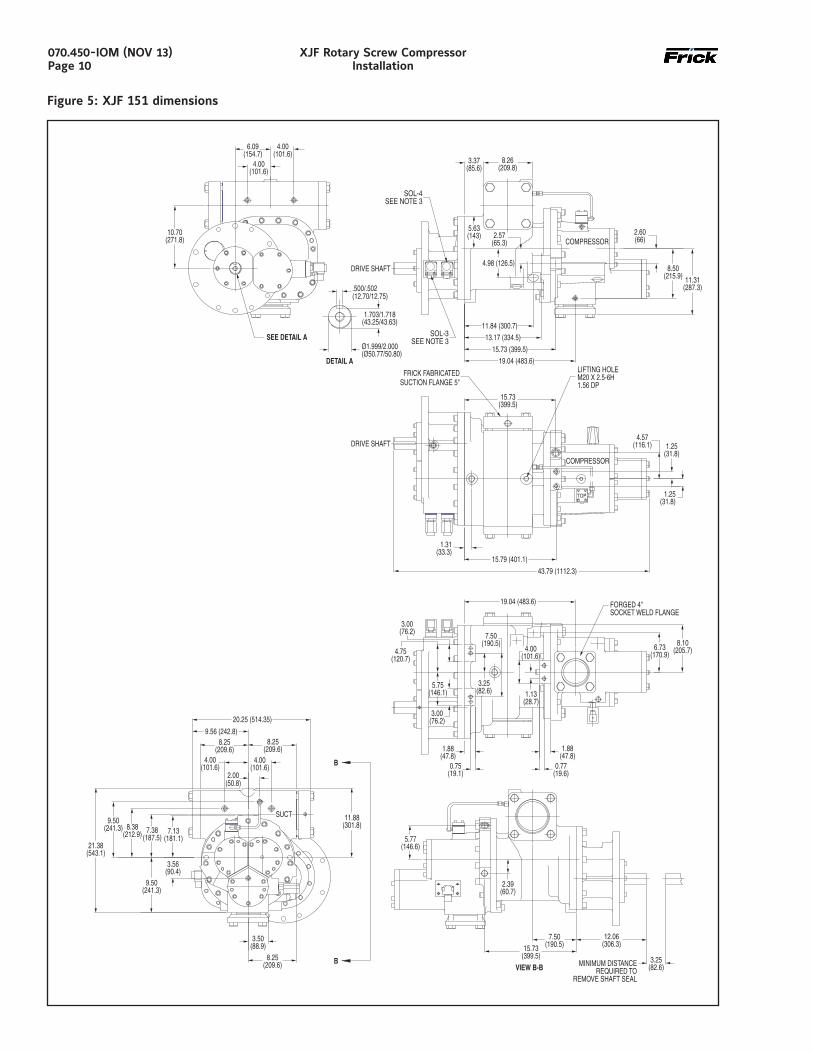
Figure 5: XJF 151 dimensions
SEE DETAIL A
11.31(287.3)
DRIVE SHAFT4.98 (126.5)
COMPRESSOR2.60(66)
10.70(271.8)
4.00(101.6)
4.00(101.6)
6.09(154.7)
3.37(85.6)
8.26(209.8)
1.31(33.3)
COMPRESSOR
21.38(543.1)
9.50(241.3)
8.38(212.9) 7.38
(187.5)
SUCT
9.56 (242.8)8.25
(209.6)8.25
(209.6)
11.88(301.8)
4.00(101.6)
4.00(101.6)
20.25 (514.35)
12.06(306.3)
7.50(190.5)
3.25(82.6)MINIMUM DISTANCE
REQUIRED TOREMOVE SHAFT SEAL
15.79 (401.1)
LIFTING HOLEM20 X 2.5-6H1.56 DP
FRICK FABRICATEDSUCTION FLANGE 5"
1.25(31.8)
4.57(116.1)
15.73(399.5)
1.25(31.8)
15.73(399.5)
7.13(181.1)
3.56(90.4)
2.57(65.3)
5.63(143)
11.84 ( )300.7
13.17 ( )334.5
15.73 ( )399.5
8.25(209.6)
3.50(88.9)
19.04 (483.6)
6.73(170.9)
8.10(205.7)
FORGED 4"SOCKET WELD FLANGE
8.50(215.9)
19.04 ( )483.6
0.75(19.1)
1.88(47.8)
0.77(19.6)
1.88(47.8)
5.77(146.6)
3.25(82.6)
3.00(76.2)
7.50(190.5)
4.00(101.6)
1.13(28.7)
5.75(146.1)
4.75(120.7)
3.00(76.2)
SOL-4SEE NOTE 3
SOL-3SEE NOTE 3
2.00(50.8)
9.50(241.3)
2.39(60.7)
DRIVE SHAFT
43.79 (1112.3)
TOP
OUT OUT
VIEW B-BB
B
DETAIL A
Ø1.999/2.000(Ø50.77/50.80)
1.703/1.718(43.25/43.63)
.500/.502(12.70/12.75)
070.450-IOM (NOV 13)Page 11
XJF Rotary Screw CompressorInstallation
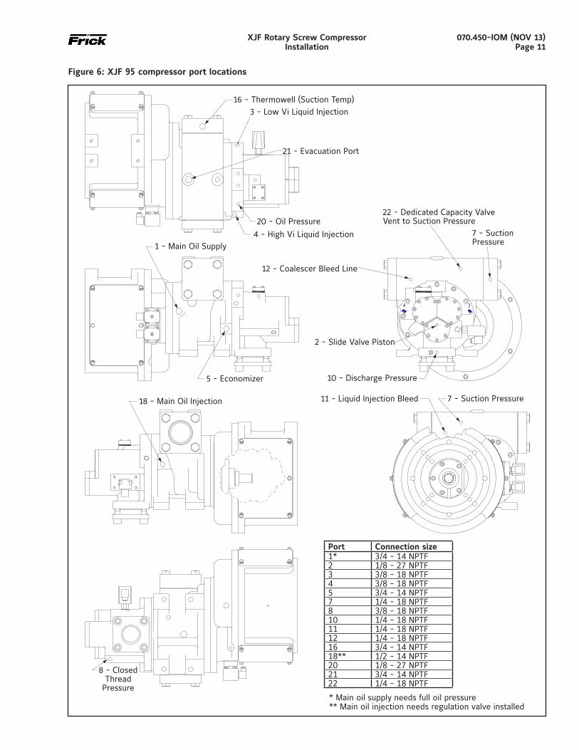
Port Connection size1* 3/4 - 14 NPTF2 1/8 - 27 NPTF3 3/8 - 18 NPTF4 3/8 - 18 NPTF5 3/4 - 14 NPTF7 1/4 - 18 NPTF8 3/8 - 18 NPTF10 1/4 - 18 NPTF11 1/4 - 18 NPTF12 1/4 - 18 NPTF16 3/4 - 14 NPTF18** 1/2 - 14 NPTF20 1/8 - 27 NPTF21 3/4 - 14 NPTF22 1/4 - 18 NPTF
Figure 6: XJF 95 compressor port locations
* Main oil supply needs full oil pressure** Main oil injection needs regulation valve installed
070.450-IOM (NOV 13)Page 12
XJF Rotary Screw CompressorInstallation
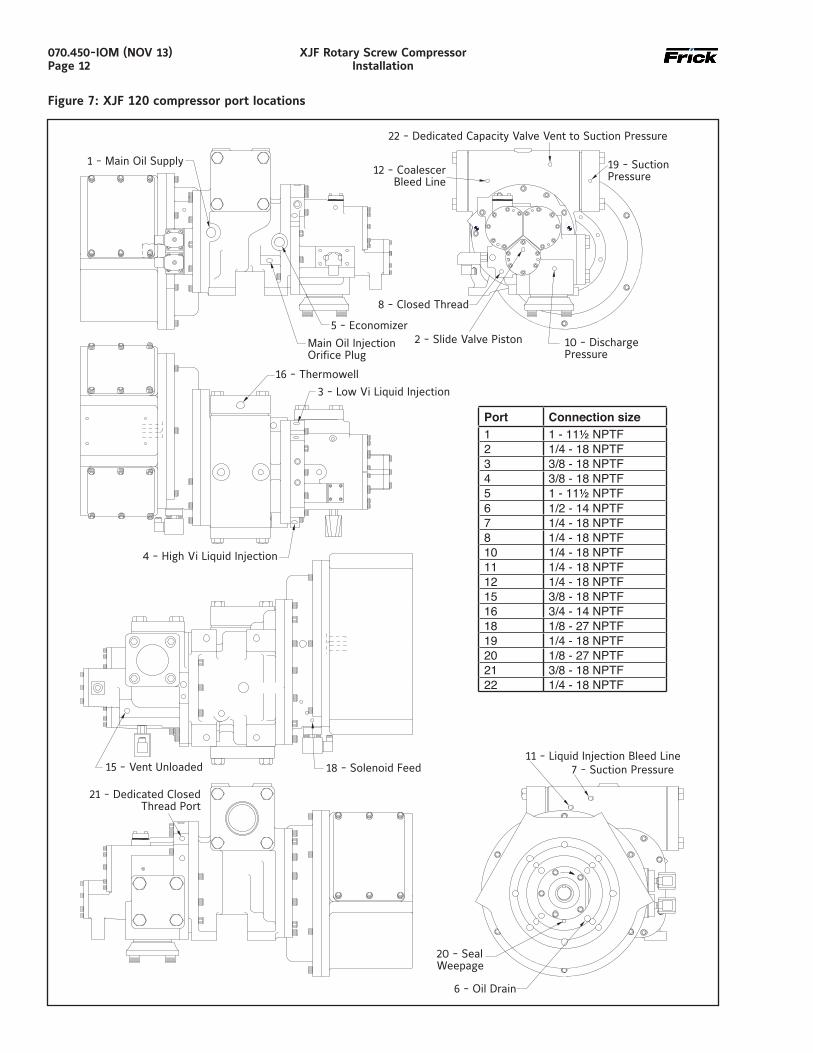
Figure 7: XJF 120 compressor port locations
Port Connection size1 1 - 11½ NPTF2 1/4 - 18 NPTF3 3/8 - 18 NPTF4 3/8 - 18 NPTF5 1 - 11½ NPTF6 1/2 - 14 NPTF7 1/4 - 18 NPTF8 1/4 - 18 NPTF10 1/4 - 18 NPTF11 1/4 - 18 NPTF12 1/4 - 18 NPTF15 3/8 - 18 NPTF16 3/4 - 14 NPTF18 1/8 - 27 NPTF19 1/4 - 18 NPTF20 1/8 - 27 NPTF21 3/8 - 18 NPTF22 1/4 - 18 NPTF
070.450-IOM (NOV 13)Page 13
XJF Rotary Screw CompressorInstallation
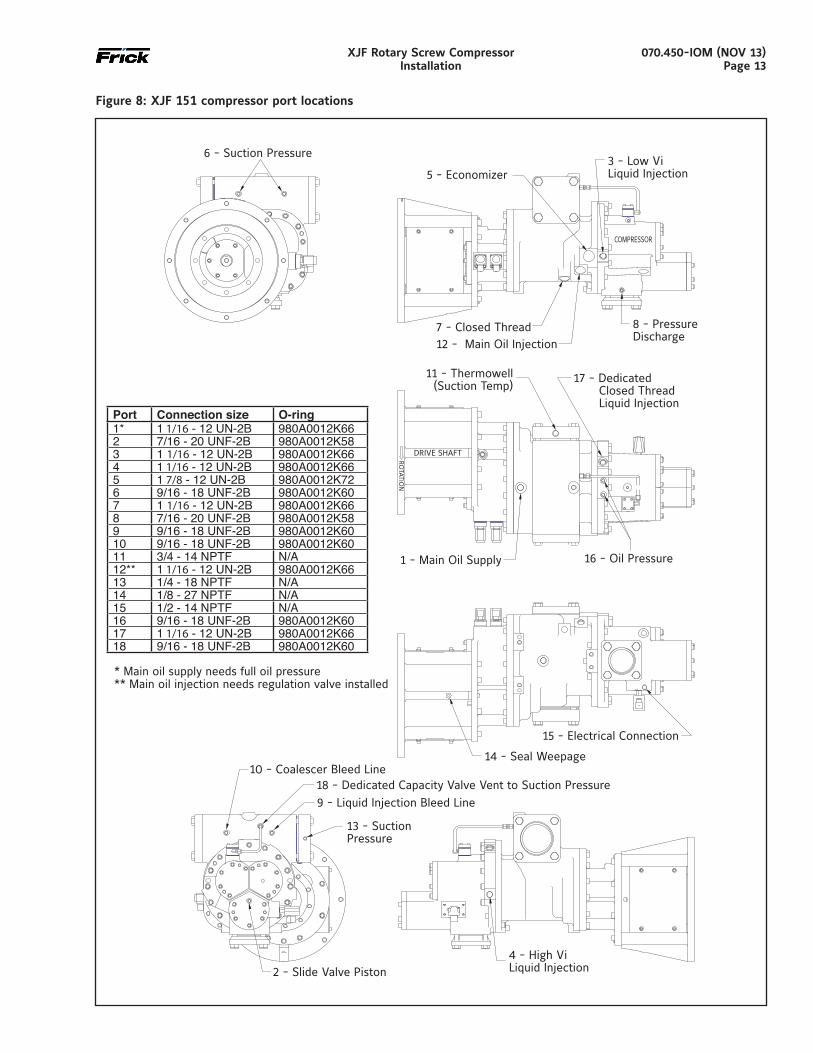
Figure 8: XJF 151 compressor port locations
Port Connection size O-ring1* 1 1/16 - 12 UN-2B 980A0012K662 7/16 - 20 UNF-2B 980A0012K583 1 1/16 - 12 UN-2B 980A0012K664 1 1/16 - 12 UN-2B 980A0012K665 1 7/8 - 12 UN-2B 980A0012K726 9/16 - 18 UNF-2B 980A0012K607 1 1/16 - 12 UN-2B 980A0012K668 7/16 - 20 UNF-2B 980A0012K589 9/16 - 18 UNF-2B 980A0012K6010 9/16 - 18 UNF-2B 980A0012K6011 3/4 - 14 NPTF N/A12** 1 1/16 - 12 UN-2B 980A0012K6613 1/4 - 18 NPTF N/A14 1/8 - 27 NPTF N/A15 1/2 - 14 NPTF N/A16 9/16 - 18 UNF-2B 980A0012K6017 1 1/16 - 12 UN-2B 980A0012K6618 9/16 - 18 UNF-2B 980A0012K60
* Main oil supply needs full oil pressure** Main oil injection needs regulation valve installed
070.450-IOM (NOV 13)Page 14
XJF Rotary Screw CompressorInstallation
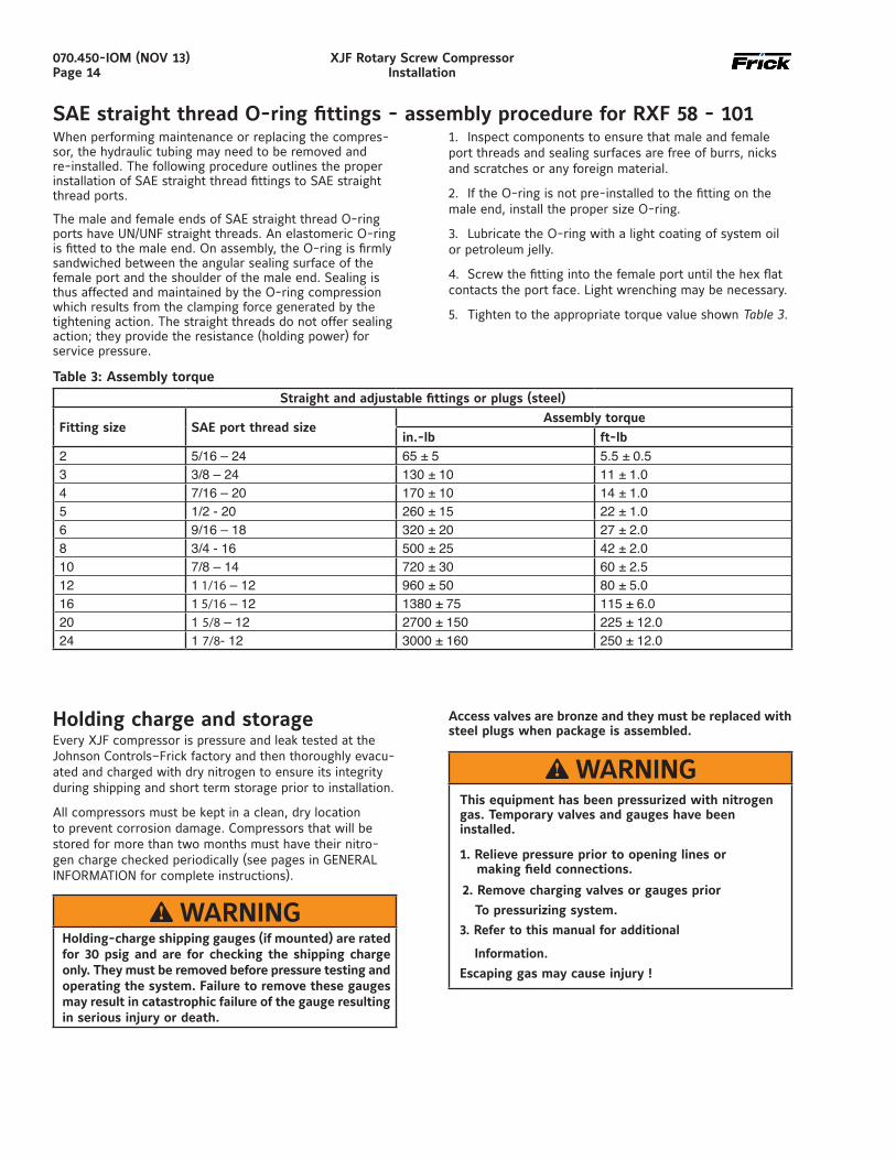
Holding charge and storageEvery XJF compressor is pressure and leak tested at the Johnson Controls–Frick factory and then thoroughly evacu-ated and charged with dry nitrogen to ensure its integrity during shipping and short term storage prior to installation.
All compressors must be kept in a clean, dry location to prevent corrosion damage. Compressors that will be stored for more than two months must have their nitro-gen charge checked periodically (see pages in GENERAL INFORMATION for complete instructions).
WARNINGHolding-charge shipping gauges (if mounted) are rated for 30 psig and are for checking the shipping charge only. They must be removed before pressure testing and operating the system. Failure to remove these gauges may result in catastrophic failure of the gauge resulting in serious injury or death.
Access valves are bronze and they must be replaced with steel plugs when package is assembled.
WARNINGThis equipment has been pressurized with nitrogen gas. Temporary valves and gauges have been installed.
1. Relieve pressure prior to opening lines or making field connections.
2. Remove charging valves or gauges prior
To pressurizing system.
3. Refer to this manual for additional
Information.
Escaping gas may cause injury !
SAE straight thread O-ring fittings - assembly procedure for RXF 58 - 1011. Inspect components to ensure that male and female port threads and sealing surfaces are free of burrs, nicks and scratches or any foreign material.
2. If the O-ring is not pre-installed to the fitting on the male end, install the proper size O-ring.
3. Lubricate the O-ring with a light coating of system oil or petroleum jelly.
4. Screw the fitting into the female port until the hex flat contacts the port face. Light wrenching may be necessary.
5. Tighten to the appropriate torque value shown Table 3.
Table 3: Assembly torque
Straight and adjustable fittings or plugs (steel)
Fitting size SAE port thread sizeAssembly torque
in.-lb ft-lb2 5/16 – 24 65 ± 5 5.5 ± 0.53 3/8 – 24 130 ± 10 11 ± 1.04 7/16 – 20 170 ± 10 14 ± 1.05 1/2 - 20 260 ± 15 22 ± 1.06 9/16 – 18 320 ± 20 27 ± 2.08 3/4 - 16 500 ± 25 42 ± 2.010 7/8 – 14 720 ± 30 60 ± 2.512 1 1/16 – 12 960 ± 50 80 ± 5.016 1 5/16 – 12 1380 ± 75 115 ± 6.020 1 5/8 – 12 2700 ± 150 225 ± 12.024 1 7/8- 12 3000 ± 160 250 ± 12.0
When performing maintenance or replacing the compres-sor, the hydraulic tubing may need to be removed and re-installed. The following procedure outlines the proper installation of SAE straight thread fittings to SAE straight thread ports.
The male and female ends of SAE straight thread O-ring ports have UN/UNF straight threads. An elastomeric O-ring is fitted to the male end. On assembly, the O-ring is firmly sandwiched between the angular sealing surface of the female port and the shoulder of the male end. Sealing is thus affected and maintained by the O-ring compression which results from the clamping force generated by the tightening action. The straight threads do not offer sealing action; they provide the resistance (holding power) for service pressure.
070.450-IOM (NOV 13)Page 15
XJF Rotary Screw CompressorInstallation
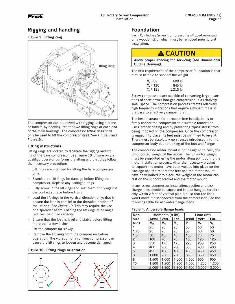
Rigging and handlingFigure 9: Lifting ring
The compressor can be moved with rigging, using a crane or forklift, by hooking into the two lifting rings at each end of the main housings. The compressor lifting rings shall only be used to lift the compressor itself. See Figure 9 and Figure 10.
Lifting instructions Lifting rings are located to facilitate the rigging and lift-ing of the bare compressor. See Figure 10. Ensure only a qualified operator performs the lifting and that they follow the necessary precautions.
• Lift rings are intended for lifting the bare compressor only.
• Examine the lift rings for damage before lifting the compressor. Replace any damaged rings.
• Fully screw in the lift rings and seat them firmly against the contact surface before lifting.
• Load the lift rings in the vertical direction only; that is, ensure the load is parallel to the threaded portion of the lift ring. See Figure 10. This may require the use of a spreader beam. Loading the lift rings at an angle reduces their load capacity.
• Ensure that the load is level and stable before lifting more than a few inches.
• Lift the compressor slowly.
• Remove the lift rings from the compressor before operation. The vibration of a running compressor can cause the lift rings to loosen and become damaged.
Figure 10: Lifting rings orientation
Foundation Each XJF Rotary Screw Compressor is shipped mounted on a wooden skid, which must be removed prior to unit installation.
CAUTIONAllow proper spacing for servicing (see Dimensional Outline Drawing).
The first requirement of the compressor foundation is that it must be able to support the weight.
XJF 95 600 lbXJF 120 845 lbXJF 151 1,210 lb
Screw compressors are capable of converting large quan-tities of shaft power into gas compression in a relatively small space. The compression process creates relatively high frequency vibrations that require sufficient mass in the base to effectively dampen them.
The best insurance for a trouble-free installation is to firmly anchor the compressor to a suitable foundation using proper bolting and by preventing piping stress from being imposed on the compressor. Once the compressor is rigged into place, its feet must be shimmed to level it. There must be absolutely no stresses introduced into the compressor body due to bolting of the feet and flanges.
The compressor motor mount is not designed to carry the unsupported weight of the motor. The full motor weight must be supported using the motor lifting point during the motor installation process. After the necessary bracket to support the motor have been welded into place on the package and the rear motor feet and the motor mount have been bolted into place, the weight of the motor can rest on the support bracket and the motor mount.
In any screw compressor installation, suction and dis-charge lines should be supported in pipe hangers (prefer-ably within 2 feet of vertical pipe run) so that the lines won’t move if disconnected from the compressor. See the following table for allowable flange loads.
Table 4: Allowable flange loads
Noz. size NPS
Moments (ft-lbf) Load (lbf)Axial Vert. Lat. Axial Vert. Lat.MR MC ML P VC VL
1 25 25 25 50 50 501.25 25 25 25 50 50 501.5 50 40 40 100 75 752 100 70 70 150 125 1253 250 175 175 225 250 2504 400 200 200 300 400 4005 425 400 400 400 450 4506 1,000 750 750 650 650 6508 1,500 1,000 1,000 1,500 900 90010 1,500 1,200 1,200 1,500 1,200 1,20014 2,000 1,800 1,800 1,700 2,000 2,000
070.450-IOM (NOV 13)Page 16
XJF Rotary Screw CompressorInstallation
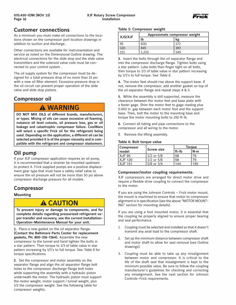
Customer connectionsAs a minimum you must make oil connections to the loca-tions shown on the compressor port location drawings in addition to suction and discharge.
Other connections are available for instrumentation and service as noted on the Dimensional Outline drawing. The electrical connections for the slide stop and the slide valve transmitters and the solenoid valve coils must be con-nected to your control system .
The oil supply system for the compressor must be de-signed for a total pressure drop of no more than 15 psi with a new oil filter element. Excessive pressure drop in the oil circuit can prevent proper operation of the slide valve and slide stop pistons.
Compressor oil WARNING
DO NOT MIX OILS of different brands, manufacturers, or types. Mixing of oils can cause excessive oil foaming, nuisance oil level cutouts, oil pressure loss, gas or oil leakage and catastrophic compressor failure. CoolWare will select a specific Frick oil for the refrigerant being used. Depending on the application, a different oil can be selected provided it is of the proper viscosity and is com-patible with the refrigerant and compressor elastomers.
Oil pumpIf your XJF compressor application requires an oil pump, it is recommended that a strainer be mounted upstream to protect it. Frick supplied pumps are a positive displace-ment gear type that must have a safety relief valve to ensure the oil pressure will not be more than 50 psi above compressor discharge pressure for all models.
CompressorMounting
CAUTIONTo prevent injury or damage to components, and for complete details regarding pressurized refrigerant va-por transfer and recovery, see the current Installation-Operation-Maintenance Manual for your unit.
1. Place a new gasket on the oil separator flange. (Contact the Baltimore Parts Center for replacement gaskets, Ph: 800-336-7264). Assemble the new compressor to the tunnel and hand tighten the bolts in a star pattern. Then torque to 1/3 of table value in star pattern increasing by 1/3’s to full torque. See Table 6 for torque specifications.
2. Set the compressor and motor assembly on the separator flange and align the oil separator flange bolt holes to the compressor discharge flange bolt holes while supporting the assembly with a hydraulic piston underneath the motor. The hydraulic piston must support the motor weight, motor support / tunnel weight, plus 1/2 the compressor weight. See the following table for compressor weights.
Table 5: Compressor weight
XJS/XJFApproximate compressor weight
lb kg95 600 272120 845 383151 1,210 549
3. Insert the bolts through the oil separator flange and into the compressor discharge flange. Tighten bolts using a star pattern. Lube bolts then finger tight on all bolts, then torque to 1/3 of table value in star pattern increasing by 1/3’s to full torque. See Table 6.
4. The motor feet should rise above the support base. If not, remove the compressor, add another gasket on top of the oil separator flange and repeat steps 4 & 5.
5. While the assembly is still supported, measure the clearance between the motor feet and base plate with a feeler gage. Shim the motor feet to gage reading plus 0.002 in. gap between each motor foot and the support base. Then, bolt the motor to the mounting base and torque the motor mounting bolts to 250 ft-lb.
6. Connect all tubing and pipe connections to the compressor and all wiring to the motor.
7. Remove the lifting assembly.
Table 6: Bolt torque valueCompressormodel
Screw sizeTorque
ft-lb N.mXJF 95 1/2 or 5/8 58 79XJF 120 1/2 or 5/8 58 79XJF 151 5/8 or 3/4 144 195
Compressor/motor coupling requirements.XJF compressors are arranged for direct motor drive and require a flexible drive coupling to connect the compressor to the motor.
If you are using the Johnson Controls – Frick motor mount, the mount is machined to ensure that motor to compressor alignment is in specification (see the above “MOTOR MOUNT-ING” section for mounting details).
If you are using a foot mounted motor, it is essential that the coupling be properly aligned to ensure proper bearing and seal performance.
1. Coupling must be selected and installed so that it doesn’t transmit any axial load to the compressor shaft.
2. Set up the minimum distance between compressor shaft and motor shaft to allow for seal removal (see Outline drawings).
3. Coupling must be able to take up any misalignment between motor and compressor. It is critical to the life of the shaft seal that misalignment is kept to the minimum possible value. Be sure to follow the coupling manufacturer’s guidelines for checking and correcting any misalignment. See the next section for Johnson Controls–Frick requirements.
070.450-IOM (NOV 13)Page 17
XJF Rotary Screw CompressorInstallation
Coupling alignment requirements (foot mounted only)Coupling alignment must be performed prior to start-up. After the compressor has been installed on the job site, alignment must be checked again and if necessary corrected prior to start-up. After a few hours operation, the alignment must be checked while the package is still hot. Correct hot alignment is critical to ensure the life of the shaft seal and compressor bearings.
Maximum radial runout is 0.004 in. total indicator reading.
Maximum axial runout is 0.004 in. total indicator reading.
A dial indicator or another appropriate measuring device is to be used to determine the Total Indicator Runout.
Indicator bracket sag must be checked as all brackets have some flexibility. The best way to measure this is to attach the dial indicator and bracket on a pipe at the coupling span distance. Zero the indicator in the 12:00 position, and rotate the pipe so the indicator is in the 6:00 position. The reading on the indicator in the 6:00 position is the bracket sag. This value must be included in the dial indicator readings when affixed to the coupling for an accurate alignment.
Oil heaters Your package must be equipped with oil heaters that pro-vide sufficient heat to prevent condensation from occur-ring during shutdown cycles.
Oil filtersYour package must be equipped with full-flow oil filtra-tion. Typical oil filter specification β5 = 75 according to ISO 4572 is required to obtain the recommended oil cleanliness class 16/14/11 according to ISO 4406. Frick SuperFilters™ can be ordered separately.
Oil cooling requirementsCompressor oil needs to be cooled to control the dis-charge temperature, maintain proper oil viscosity and to preserve the life of the oil. Normally the discharge temperature will be in the 170° - 180°F range (see Cool-Ware™).
One application that typically requires higher discharge temperatures (as high as 250°F) is natural gas gathering at the wellhead 1. Moisture is normally present in the gas and it is imperative that the discharge temperature be at least 30°F higher than the discharge dew point temperature for the gas. Run Coolware with the “Water Saturated” block checked to get the discharge dew point temperature for your application. Oil temperatures as high as 170°F can be used to achieve the necessary discharge temperature to prevent moisture from condensing in the oil separator. 1 Contact Johnson Controls–Frick for additional informa-tion for natural gas compression - availability of bearings for high temperature applications - standard bearings have limitations per Coolware that must be observed.
The main oil injection line must have a regulating valve to permit adjustment of the oil flow to maintain the desired discharge temperature at all times.
The use of a three-way mixing valve is recommended to keep the oil temperature in the normal range of 120° - 140°F. The valve will provide warm oil to the compres-sor quickly, reducing the pressure drop caused by cold, viscous oil. This ensures proper oil flow and temperature over the full range of operating conditions.
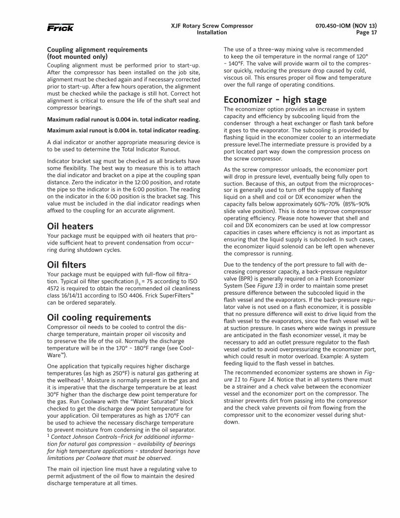
Economizer - high stageThe economizer option provides an increase in system capacity and efficiency by subcooling liquid from the condenser through a heat exchanger or flash tank before it goes to the evapora tor. The subcooling is provided by flashing liquid in the economizer cooler to an intermediate pressure level.The intermediate pressure is provided by a port located part way down the compres sion process on the screw compressor.
As the screw compressor unloads, the economizer port will drop in pressure level, eventually being fully open to suction. Because of this, an output from the microproces-sor is generally used to turn off the supply of flashing liquid on a shell and coil or DX economizer when the capacity falls below approximately 60%-70% (85%-90% slide valve position). This is done to improve compressor operating efficiency. Please note however that shell and coil and DX economizers can be used at low compressor capaciti es in cases where efficien cy is not as important as ensuring that the liquid supply is subcooled. In such cases, the economi zer liquid solenoid can be left open whenever the com pressor is running.
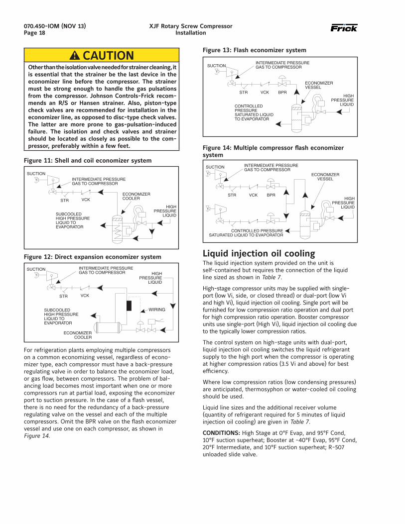
Due to the tendency of the port pressure to fall with de-creasing compressor capacity, a back-pressure regulator valve (BPR) is generally required on a Flash Economizer System (See Figure 13) in order to maintain some preset pressure dif ference between the subcooled liquid in the flash vessel and the evaporato rs. If the back-pressure regu-lator valve is not used on a flash economizer, it is possible that no pressure difference will exist to drive liquid from the flash vessel to the evaporators, since the flash vessel will be at suction pressure. In cases where wide swings in pressure are anticipated in the flash econo mizer vessel, it may be necessary to add an outlet pressure regulator to the flash vessel outlet to avoid overpressurizing the economizer port, which could result in motor overload. Example: A system feeding liquid to the flash vessel in batches.
The recommended economizer systems are shown in Fig-ure 11 to Figure 14. Notice that in all systems there must be a strainer and a check valve between the economizer vessel and the economizer port on the compressor. The strainer prevents dirt from passing into the compressor and the check valve prevents oil from flowing from the compressor unit to the econo mizer vessel during shut-down.
070.450-IOM (NOV 13)Page 18
XJF Rotary Screw CompressorInstallation
CAUTIONOther than the isolation valve needed for strainer cleaning, it is essential that the strainer be the last device in the economizer line before the compres sor. The strainer must be strong enough to handle the gas pulsations from the compressor. Johnson Controls-Frick recom-mends an R/S or Hansen strainer. Also, piston-type check valves are recom mended for installation in the economizer line, as opposed to disc-type check valves. The latter are more prone to gas-pulsation-induced failure. The isolation and check valves and strainer should be located as closely as possible to the com-pressor, preferably within a few feet.
Figure 11: Shell and coil economizer system
Figure 12: Direct expansion economizer system
For refrigeration plants employing multiple compressors on a common economizing vessel, regardless of econo-mizer type, each compressor must have a back-pressure regulat ing valve in order to balance the economizer load, or gas flow, between compressors. The problem of bal-ancing load becomes most important when one or more compressors run at partial load, exposing the economizer port to suction pressure. In the case of a flash vessel, there is no need for the redundancy of a back-pressure regulating valve on the vessel and each of the multiple compressors. Omit the BPR valve on the flash economizer vessel and use one on each compressor, as shown in Figure 14.
Figure 13: Flash economizer system
Figure 14: Multiple compressor flash economizer system
Liquid injection oil coolingThe liquid injection system provided on the unit is self-con tained but requires the connection of the liquid line sized as shown in Table 7.
High-stage compressor units may be supplied with single-port (low Vi, side, or closed thread) or dual-port (low Vi and high Vi), liquid injection oil cooling. Single port will be furnished for low compression ratio operation and dual port for high compression ratio operation. Booster compressor units use single-port (High Vi), liquid injection oil cooling due to the typically lower compression ratios.
The control system on high-stage units with dual-port, liquid injection oil cooling switches the liquid refrigerant supply to the high port when the compres sor is operating at higher compression ratios (3.5 Vi and above) for best efficiency.
Where low compres sion ratios (low condensing pressures) are anticipated, thermo syphon or water-cooled oil cooling should be used.
Liquid line sizes and the additional receiver volume (quanti ty of refrigerant required for 5 minutes of liquid injection oil cooling) are given in Table 7.
CONDITIONS: High Stage at 0°F Evap, and 95°F Cond, 10°F suction superheat; Booster at -40°F Evap, 95°F Cond, 20°F Intermediate, and 10°F suction superheat; R-507 unloaded slide valve.
070.450-IOM (NOV 13)Page 19
XJF Rotary Screw CompressorInstallation
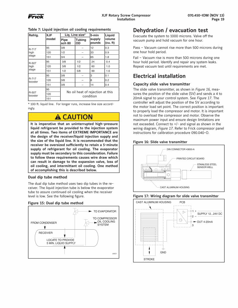
Table 7: Liquid injection oil cooling requirements
Refrig. XJFmodel
Liq. Line size* 5-minsupplypounds
Liquidvolume(cu. ft)
Pipesch 80
TubingOD
R-717highstage
95 3/8 – 12 0.3120 1/2 – 33 0.9151 3/4 – 65 1.8
R-507highstage
95 3/8 1/2 24 0.4120 3/8 1/2 60 1.0151 1/2 5/8 99 1.6
R-717booster
95 3/8 – 3 0.1120 3/8 – 8 0.2151 3/8 – 14 0.4
R-507booster
95No oil heat of rejection at this
condition120151
* 100 ft. liquid line. For longer runs, increase line size accord-ingly.
CAUTIONIt is imperative that an uninterrupted high-pres sure liquid refrig erant be provided to the injection system at all times. Two items of EXTREME IMPORTANCE are the design of the receiver/liquid injection supply and the size of the liquid line. It is recommended that the receiver be oversized sufficiently to retain a 5-minute supply of refrigerant for oil cooling. The evaporator supply must be secondary to this considera tion. Failure to follow these requirements causes wire draw which can result in damage to the expansion valve, loss of oil cooling, and intermittant oil cooling. One method of ac complishing this is described below.
Dual dip tube method
The dual dip tube method uses two dip tubes in the re-ceiv er. The liquid injection tube is below the evaporator tube to assure continued oil cooling when the receiver level is low. See the following figure.
Figure 15: Dual dip tube method
Dehydration / evacuation testEvacuate the system to 1000 microns. Valve off the vacuum pump and hold vacuum for one hour.
Pass – Vacuum cannot rise more than 500 microns during one hour hold period.
Fail – Vacuum rise is more than 500 microns during one hour hold period. Identify and repair any system leaks. Repeat vacuum test until requirements are met.
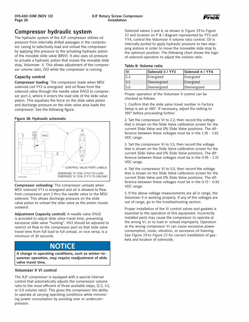
Electrical installationCapacity slide valve transmitterThe slide valve transmitter, as shown in Figure 16, mea-sures the position of the slide valve (SV) and sends a 4 to 20mA signal to your control system. See Figure 17. The controller will adjust the position of the SV according to the motor load set point. The correct position is important to properly load the compressor and motor. It is important not to overload the compressor and motor. Observe the maximum power input and ensure design limitations are not exceeded. Connect to +/- and signal as shown in the wiring diagram, Figure 17. Refer to Frick compressor panel instructions for calibration procedure 090.040-O.
Figure 16: Slide valve transmitter
Figure 17: Wiring diagram for slide valve transmitter
070.450-IOM (NOV 13)Page 20
XJF Rotary Screw CompressorInstallation
Compressor hydraulic systemThe hydraulic system of the XJF compressor utilizes oil pressure from internally drilled passages in the compres-sor casing to selectively load and unload the compressor by applying this pressure to the actuating hydraulic piston of the movable slide valve (MSV). It also uses oil pressure to actuate a hydraulic piston that moves the movable slide stop, Volumizer II. This allows adjustment of the compres-sor volume ratio, (Vi) while the compressor is running.
Capacity controlCompressor loading: The compressor loads when MSV solenoid coil YY2 is energized and oil flows from the solenoid valve through the needle valve (HV2) to compres-sor port 2, where it enters the load side of the slide valve piston. This equalizes the force on the slide valve piston and discharge pressure on the slide valve area loads the compressor. See the following figure.
Figure 18: Hydraulic schematic
Compressor unloading: The compressor unloads when MSV solenoid YY1 is energized and oil is allowed to flow from compressor port 2 thru the needle valve to the MSV solenoid. This allows discharge pressure on the slide valve piston to unload the slide valve as the piston moves outward.
Adjustment (capacity control): A needle valve (HV2) is provided to adjust slide valve travel time, preventing excessive slide valve “hunting”. HV2 should be adjusted to restrict oil flow to the compressor port so that slide valve travel time from full load to full unload, or vice versa, is a minimum of 30 seconds.
NOTICEA change in operating conditions, such as winter-to-summer operation, may require readjustment of slide valve travel time.
Volumizer II Vi control
The XJF compressor is equipped with a special internal control that automatically adjusts the compressor volume ratio to the most efficient of three available steps, (2.2, 3.5, or 5.0 volume ratio). This gives the compressor the ability to operate at varying operating conditions while minimiz-ing power consumption by avoiding over or undercom-pression.
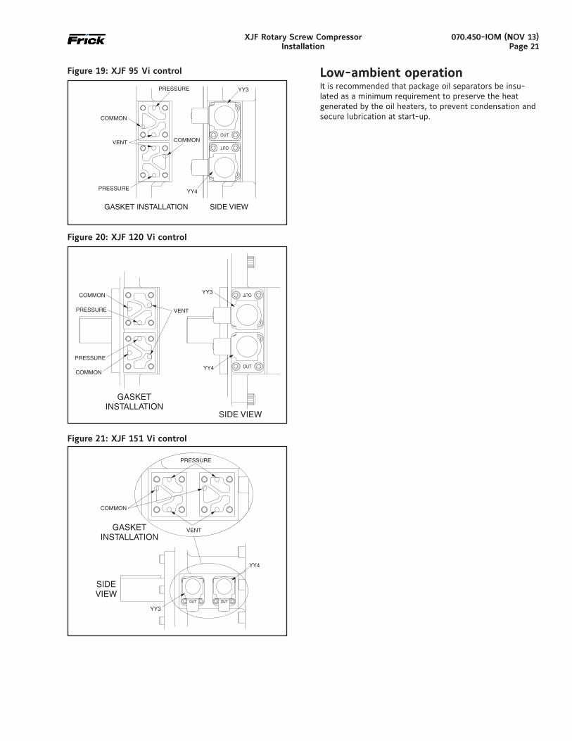
Solenoid valves 3 and 4, as shown in Figure 19 to Figure 21 and location on P & I diagram represented by YY3 and YY4, control the Volumizer II volume ratio control. Oil is internally ported to apply hydraulic pressure to two step-ping pistons in order to move the moveable slide stop to the optimum position. The following chart shows the logic of solenoid operation to adjust the volume ratio.
Table 8: Volume ratio
Vi Solenoid 3 / YY3 Solenoid 4 / YY42.2 Energized Energized3.5 Deenergized Energized5.0 Deenergized Deenergized
Proper operation of the Volumizer II control can be checked as follows.
1. Confirm that the slide valve travel number in Factory Setup is set at 190°. If necessary, adjust the setting to 190° before proceeding further.
2. Set the compressor Vi to 2.2, then record the voltage that is shown on the Slide Valve calibration screen for the current Slide Valve and 0% Slide Valve positions. The dif-ference between these voltages must be in the 1.35 - 1.65 VDC range.
3. Set the compressor Vi to 3.5, then record the voltage that is shown on the Slide Valve calibration screen for the current Slide Valve and 0% Slide Valve positions. The dif-ference between these voltages must be in the 0.95 - 1.15 VDC range.
4. Set the compressor Vi to 5.0, then record the voltage that is shown on the Slide Valve calibration screen for the current Slide Valve and 0% Slide Valve positions. The dif-ference between these voltages must be in the 0.73 - 0.93 VDC range.
5. If the above voltage measurements are all in range, the Volumizer II is working properly. If any of the voltages are out of range, go to the troubleshooting section.
Proper installation of the Vi control valves and gaskets is essential to the operation of this equipment. Incorrectly installed parts may cause the compressor to operate at the wrong Vi, or to load or unload improperly. Operation at the wrong compressor Vi can cause excessive power consumption, noise, vibration, or excessive oil foaming. See Figure 19 to Figure 21 for correct installation of gas-kets and location of solenoids.
070.450-IOM (NOV 13)Page 21
XJF Rotary Screw CompressorInstallation
Figure 19: XJF 95 Vi control
OUT
OUT
GASKET INSTALLATION SIDE VIEW
PRESSURE
PRESSURE
COMMON
COMMON
VENT
YY3
YY4
Figure 20: XJF 120 Vi control
Figure 21: XJF 151 Vi control
Low-ambient operation It is recommended that package oil separators be insu-lated as a minimum requirement to preserve the heat generated by the oil heaters, to prevent condensation and secure lubrication at start-up.

070.450-IOM (NOV 13)Page 22
XJF Rotary Screw CompressorInstallation
This page is intentionally left blank.
070.450-IOM (NOV 13)Page 23
XJF Rotary Screw CompressorOperation - Maintenance
Maintenance
General information This section provides instructions for normal maintenance, a recommended maintenance program, and troubleshoot-ing and correction guides.
WARNINGThis section must be read and understood before at-tempting to perform any maintenance or service to the unit.
WARNINGCompressor surfaces, especially those on the discharge housing, may become hot during operation. Addition-ally, surfaces near the suction flange may be cold. Contact with compressor surfaces during or soon after operation may cause burns. If it is likely that anyone may touch the compressor during operation and the conditions are such that burns may occur, the packager must implement protection measures. For compressors that must comply with the Machinery Directive, refer to the requirements of EN ISO 13732-1.
WARNINGOpening any part of the compressor unit to atmosphere while under pressure may cause injury. Ensure that the compressor pressure is at 0 psig before removing any pressure containing part.
CAUTIONCylinder assembly under high spring load. Consult manual before disassembly. Improper disassembly may cause injury due to spring tension release.
Normal maintenance operations When performing maintenance you must take several precautions to ensure your safety:
1. If unit is running, press [Stop] key.
2. Stop motor and lock out starter before performing any maintenance.
3. Wear proper safety equipment when compressor unit is opened to atmosphere.
4. Ensure adequate ventilation.
5. Take necessary safety precautions required for the gas being used.
Operation
Operation and start-up instructions The Frick XJF Rotary Screw Compressor will be a com-ponent in an integrated system. As such the compressor requires some specific operation and conditions to ensure trouble-free running.
The information in this section of the manual provides the logical step-by-step instructions to properly start up and operate the XJF Rotary Screw Compressor in your Unit. Only matters which may influence the proper operation of the XJF compressor are included.
WARNINGThe compression process creates noise and operating screw compressors are loud. Wear the correct hearing protection when near the compressor during opera-tion. If people are expected to be in the vicinity of the running compressor for extended time periods, provide warnings.
NOTICEThe following subsections must be read and understood before attempting to start or operate the unit.
Initial start-up Prior to the start-up, the prestart check must be accom-plished. See Prestart Checklist in FORMS section of this manual.
Initial start-up procedure Having performed the prestart check, the compressor unit is ready for start-up. It is important that an adequate gas load be available to load test the unit at normal operating conditions. The following points should be kept in mind during initial start-up.
1. For proper and safe operation, the compressor must be run at the proper speed and discharge pressure. Exceeding design conditions creates a potential hazard.
2. After 1 to 3 hours of operation adjust oil cooling system.
3. Pull and clean suction strainer after 24 hours of opera-tion. If it is excessively dirty, repeat every 24 hours until system is clean. Otherwise, follow the normal mainte-nance schedule.
4. Perform vibration analysis if equipment is available.
Normal start-up procedure 1. Confirm system conditions permit starting the compres-sor.
2. Start.
3. Observe the compressor unit for mechanical tightness of the external piping, bolts and valves. Ensure that the machine has no oil and vapor leaks. If any of these occur, shut down the compressor and correct the problem as necessary using good safety precautions.
070.450-IOM (NOV 13)Page 24
XJF Rotary Screw CompressorMaintenance
General maintenance Proper maintenance is important in order to assure long and trouble-free service from your screw compressor. Some areas critical to good compressor operation are:
1. Keep oil clean and dry, avoid moisture contamina-tion: After servicing any portion of the refrigeration system, evacuate to remove moisture before returning to service. Water vapor condensing in the compressor while running or more likely while shut down, can cause rusting of critical components and reduce life.
2. Keep suction strainer clean: Check periodically, particularly on new systems where welding slag or pipe scale could find its way to the compressor suction. Exces-sive dirt in the suction strainer could cause it to collapse, dumping particles into the compressor.
3. Keep oil filters clean: If filters show increasing pressure drop, indicating dirt or water, stop the compressor and change filters. Running a compressor for long periods with high filter pressure drop can starve the compressor of oil and lead to premature bearing failure. Dual oil filters are recommended so that the filters can be changed without shutting down the package.
4. Avoid slugging the compressor with liquids (oil): While screw compressors are probably the most tolerant of any compressor type available today about ingestion of some liquid, they are not liquid pumps. Make certain a properly sized suction accumulator is used to avoid dump-ing liquid into compressor suction.
5. Protect the compressor during long periods of shut-down: If the compressor will be sitting for long periods without running, it is advisable to evacuate to low pres-sure and charge with dry nitrogen or oil. This is particu-larly true on systems known to contain water vapor.
6. Preventive maintenance inspection is recommended any time a compressor exhibits a noticeable change in vibration level, noise, or performance.
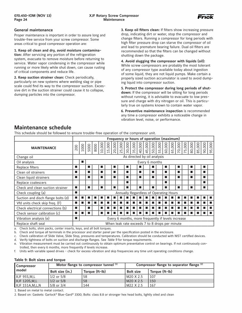
Maintenance scheduleThis schedule should be followed to ensure trouble-free operation of the compressor unit.
Frequency or hours of operation (maximum)
MAINTENANCE 200
1000
5000
8000
10,0
00
15,0
00
20,0
00
25,0
00
30,0
00
35,0
00
40,0
00
45,0
00
50,0
00
55,0
00
60,0
00
65,0
00
70,0
00
75,0
00
80,0
00
85,0
00
90,0
00
95,0
00
Change oil As directed by oil analysis
Oil analysis n Every 6 monthsReplace filters n n n n n n n n n n n
Clean oil strainers n n n n n n n n n n n
Clean liquid strainers n n n n n n n n n n n
Replace coalescers n n n
Check and clean suction strainer n n n n n n n n n n n
Check coupling (a) n Annually Regardless of Operating HoursSuction and disch flange bolts (d) n n n n n n n n n n n n n n n n n n n n n n
Vfd units check skip freq. (F) n n n n n n n n n n n n n n n n n n n n n n
Check electrical connections (b) n n n n n n n n n n n n n n n n n n n n
Check sensor calibration (c) n n n n n n n n n n n n n n n n n n n n n
Vibration analysis (e) n Every 6 months, more frequently if levels increaseReplace shaft seal When leak rate exceeds 7 to 8 drops per minute
a. Check bolts, shim packs, center inserts, keys, and all bolt torques.b. Check and torque all terminals in the processor and starter panel per the specification posted in the enclosure.c. Check calibration of Slide Valve, Slide Stop, pressures and temperatures. Calibration should be conducted with NIST certified devices.d. Verify tightness of bolts on suction and discharge flanges. See Table 9 for torque requirements.e. Vibration measurement must be carried out continuously to obtain optimum preventative control on bearings. If not continuously con-
trolled, then every 6 months, more frequently if levels increase.f. Units with variable speed drives - check for excess vibration and skip frequencies any time unit operating conditions change.
1. Based on metal to metal contact.2. Based on: Gaskets: Garlock® Blue-Gard® 3300; Bolts: class 8.8 or stronger hex head bolts, lightly oiled and clean
Compressor model
Motor flange to compressor tunnel (1) Compressor flange to separator flange (2)
Bolt size (in.) Torque (ft-lb) Bolt size Torque (ft-lb)XJF 95S,M,L 1/2 or 5/8 58 M20 X 2.5 107XJF 120S,M,L 1/2 or 5/8 58 M20 X 2.5 150XJF 151A,M,L,N 5/8 or 3/4 144 M22 X 2.5 167
Table 9: Bolt sizes and torque
070.450-IOM (NOV 13)Page 25
XJF Rotary Screw CompressorMaintenance
Changing oil
WARNINGDO NOT MIX OILS of different brands, manufacturers, or types. Mixing of oils may cause excessive oil foaming, nuisance oil level cutouts, oil pressure loss, gas or oil leakage and catastrophic compressor failure.
Shut down the unit when changing oil. At the same time all oil filter cartridges must be changed and all oil strainer ele-ments removed and cleaned. The procedure is as follows:
1. Stop the compressor unit. 2. Lock out the motor starter.3. Close the suction and discharge service valves4. Using appropriate equipment, lower the compressor
pressure to 0 psig.5. Open the drain valves and drain oil into a suitable con-
tainer.6. Drain the oil filters and the oil coolers.7. Remove the old filter cartridges, and install new ones.8. Remove, clean, and reinstall elements in the strainers. 9. Evacuate the unit.10. Open the suction service valve and pressurize the unit
to system suction pressure. Close the suction valve and leak test.
11. Add oil.12. Open the suction and discharge service valves13. Remove the lockout from the motor starter. 14. Start the unit
Note: Allow time for oil to cool before opening the drain plugs.
Recommended maintenance program In order to obtain maximum compressor performance and ensure reliable operation, a regular maintenance program should be followed. The compressor unit should be checked regularly for leaks, abnormal vibration, noise, and proper operation. A log should also be maintained. Oil analysis should be performed on a regular basis. It is a valuable tool that can identify the presence of moisture, acid, metallics and other contaminants that will shorten compressor life if not corrected. In addition, an analysis of the compressor vibration should be made periodically.
Vibration analysis Periodic vibration analysis can be useful in detecting bearing wear and other mechanical failures. If vibration analysis is used as a part of your preventive maintenance program, take the following guidelines into consideration.
1. Always take vibration readings from exactly the same places and at exactly the same percentage of load. 2. Use vibration readings taken from the new unit at start-up as the baseline reference. 3. Evaluate vibration readings carefully as the instrument range and function used can vary. Findings can be easily misinterpreted. 4. Vibration readings can be influenced by other equip-ment operating in the vicinity or connected to the same piping as the unit.
Oil quality and analysis High quality and suitable oil is necessary to ensure com-pressor longevity and reliability. Oil quality will rapidly de-teriorate in systems containing moisture and air or other contaminants. In order to ensure the quality of the oil in the compressor unit:
1. Only use Frick oil or high quality oils approved by John-son Controls - Frick for your application.
2. Only use Frick filter elements. Substitutions must be ap-proved in writing by Johnson Controls - Frick engineer-ing or warranty claim may be denied.
3. Participate in a regular, periodic oil analysis program to maintain oil and system integrity.
Operating log The use of an operating log as included in this manual permits thorough analysis of the operation of a system by those responsible for its maintenance and servicing. Continual recording of gauge pressures, temperatures, and other pertinent information, enables the observer and serviceman to be constantly familiar with the operation of the system and to recognize immediately any deviations from normal operating conditions. It is recommended that readings be taken at least daily.
Maintenance schedule The schedule below should be followed to ensure trouble-free operation of the compressor unit.
Troubleshooting guide Successful problem solving requires an organized approach to define the problem, identify the cause, and make the proper correction. Sometimes it is possible that two relatively obvious problems combine to provide a set of symptoms that can mislead the troubleshooter. Be aware of this possibility and avoid solving the “wrong problem”.
Abnormal operation analysis and correction Four logical steps are required to analyze an operational problem effectively and make the necessary corrections:
1. Define the problem and its limits. 2. Identify all possible causes. 3. Test each cause until the source of the problem is found. 4. Make the necessary corrections.
The first step in effective problem solving is to define the limits of the problem. The following list of abnormal system condi-tions can cause abnormal operation of the XJF compressor:
1. Insufficient or excessive refrigerant or gas load. 2. Excessively high suction pressure. 3. Excessively high discharge pressure. 4. Excessively high or low temperature coolant to the oil
cooler. 5. Excessive liquid entering the compressor (slugging). 6. Insufficient oil cooling.7. Excessive oil cooling8. Incorrect gas line sizing. 9. Improper system piping. 10. Wrong operation of hydraulic operated slide valve.11. Problems in electrical service to compressor. 12. Moisture present in the system.
070.450-IOM (NOV 13)Page 26
XJF Rotary Screw CompressorMaintenance
Make a list of all deviations from normal compressor operation. Delete any items, which do not relate to the symptom and separately list those items that might relate to the symptom. Use the list as a guide to further investi-gate the problem.
The second step in problem solving is to decide which items on the list are possible causes and which items are additional symptoms. High discharge temperature and high oil temperature readings on a display may both be symp-toms of a problem and not causally related.
The third step is to identify the most likely cause and take action to correct the problem. If the symptoms are not relieved, move on to the next item on the list and repeat the procedure until you have identified the cause of the problem. Once the cause has been identified and con-firmed make the necessary corrections.
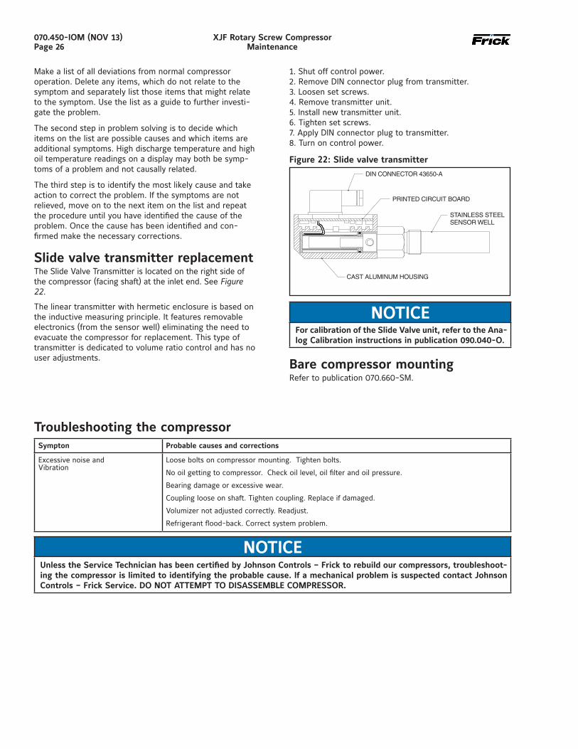
Slide valve transmitter replacementThe Slide Valve Transmitter is located on the right side of the compressor (facing shaft) at the inlet end. See Figure 22.
The linear transmitter with hermetic enclosure is based on the inductive measuring principle. It features removable electronics (from the sensor well) eliminating the need to evacuate the compressor for replacement. This type of transmitter is dedicated to volume ratio control and has no user adjustments.
1. Shut off control power.2. Remove DIN connector plug from transmitter.3. Loosen set screws.4. Remove transmitter unit.5. Install new transmitter unit.6. Tighten set screws.7. Apply DIN connector plug to transmitter.8. Turn on control power.
Figure 22: Slide valve transmitter
NOTICEFor calibration of the Slide Valve unit, refer to the Ana-log Calibration instructions in publication 090.040-O.
Bare compressor mountingRefer to publication 070.660-SM.
Troubleshooting the compressorSympton Probable causes and corrections
Excessive noise andVibration
Loose bolts on compressor mounting. Tighten bolts.
No oil getting to compressor. Check oil level, oil filter and oil pressure.
Bearing damage or excessive wear.
Coupling loose on shaft. Tighten coupling. Replace if damaged.
Volumizer not adjusted correctly. Readjust.
Refrigerant flood-back. Correct system problem.
NOTICEUnless the Service Technician has been certified by Johnson Controls – Frick to rebuild our compressors, troubleshoot-ing the compressor is limited to identifying the probable cause. If a mechanical problem is suspected contact Johnson Controls – Frick Service. DO NOT ATTEMPT TO DISASSEMBLE COMPRESSOR.
070.450-IOM (NOV 13)Page 27
XJF Rotary Screw CompressorMaintenance
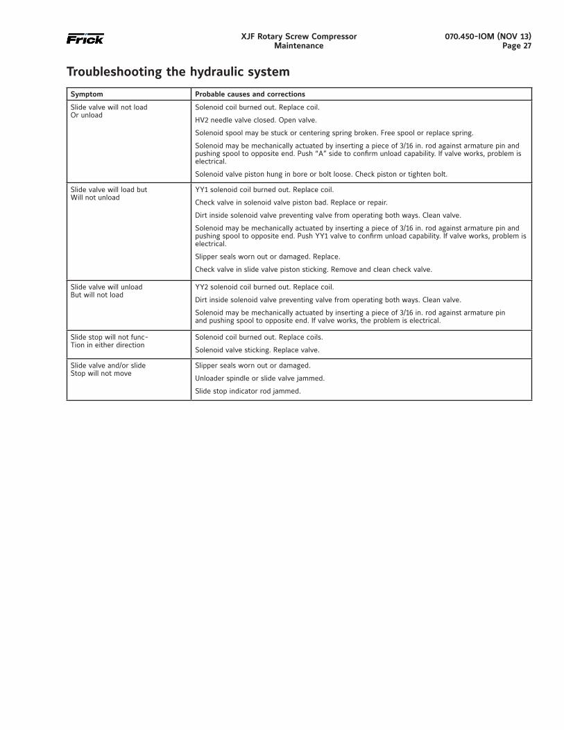
Troubleshooting the hydraulic system
Symptom Probable causes and corrections
Slide valve will not loadOr unload
Solenoid coil burned out. Replace coil.
HV2 needle valve closed. Open valve.
Solenoid spool may be stuck or centering spring broken. Free spool or replace spring.
Solenoid may be mechanically actuated by inserting a piece of 3/16 in. rod against armature pin and pushing spool to opposite end. Push “A” side to confirm unload capability. If valve works, problem is electrical.
Solenoid valve piston hung in bore or bolt loose. Check piston or tighten bolt.
Slide valve will load butWill not unload
YY1 solenoid coil burned out. Replace coil.
Check valve in solenoid valve piston bad. Replace or repair.
Dirt inside solenoid valve preventing valve from operating both ways. Clean valve.
Solenoid may be mechanical ly actuated by inserting a piece of 3/16 in. rod against armature pin and pushing spool to opposite end. Push YY1 valve to confirm unload capability. If valve works, problem is electrical.
Slipper seals worn out or damaged. Replace.
Check valve in slide valve piston sticking. Remove and clean check valve.
Slide valve will unloadBut will not load
YY2 solenoid coil burned out. Replace coil.
Dirt inside solenoid valve preventing valve from operating both ways. Clean valve.
Solenoid may be mechanically actuated by inserting a piece of 3/16 in. rod against armature pinand pushing spool to opposite end. If valve works, the problem is electrical.
Slide stop will not func-Tion in either direction
Solenoid coil burned out. Replace coils.
Solenoid valve sticking. Replace valve.
Slide valve and/or slideStop will not move
Slipper seals worn out or damaged.
Unloader spindle or slide valve jammed.
Slide stop indicator rod jammed.
070.450-IOM (NOV 13)Page 28
XJF Rotary Screw CompressorMaintenance
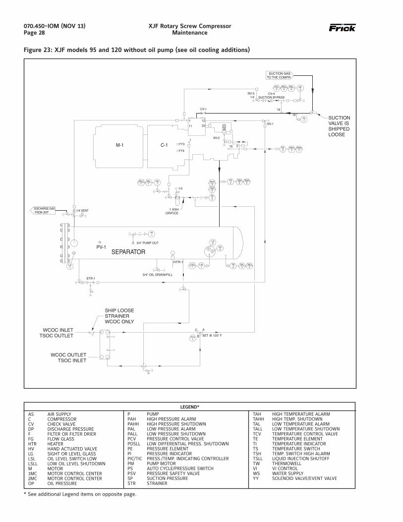
Figure 23: XJF models 95 and 120 without oil pump (see oil cooling additions)
* See additional Legend items on opposite page.
LEGEND*
AS AIR SUPPLY C COMPRESSOR CV CHECK VALVE DP DISCHARGE PRESSURE F FILTER OR FILTER DRIER FG FLOW GLASS HTR HEATER HV HAND ACTUATED VALVE LG SIGHT OR LEVEL GLASS LSL OIL LEVEL SWITCH LOW LSLL LOW OIL LEVEL SHUTDOWN M MOTOR 1MC MOTOR CONTROL CENTER 2MC MOTOR CONTROL CENTER OP OIL PRESSURE
P PUMP PAH HIGH PRESSURE ALARM PAHH HIGH PRESSURE SHUTDOWN PAL LOW PRESSURE ALARM PALL LOW PRESSURE SHUTDOWN PCV PRESSURE CONTROL VALVE PDSLL LOW DIFFERENTIAL PRESS. SHUTDOWN PE PRESSURE ELEMENT PI PRESSURE INDICATOR PIC/TIC PRESS./TEMP. INDICATING CONTROLLER PM PUMP MOTOR PS AUTO CYCLE/PRESSURE SWITCH PSV PRESSURE SAFETY VALVE SP SUCTION PRESSURE STR STRAINER
TAH HIGH TEMPERATURE ALARM TAHH HIGH TEMP. SHUTDOWN TAL LOW TEMPERATURE ALARM TALL LOW TEMPERATURE SHUTDOWN TCV TEMPERATURE CONTROL VALVE TE TEMPERATURE ELEMENT TI TEMPERATURE INDICATOR TS TEMPERATURE SWITCH TSH TEMP. SWITCH HIGH ALARM TSLL LIQUID INJECTION SHUTOFF TW THERMOWELL VI VI CONTROL WS WATER SUPPLY YY SOLENOID VALVE/EVENT VALVE
P and I drawings
070.450-IOM (NOV 13)Page 29
XJF Rotary Screw CompressorMaintenance
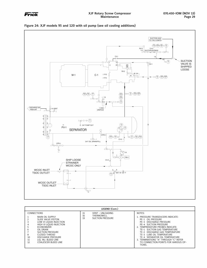
Figure 24: XJF models 95 and 120 with oil pump (see oil cooling additions)
CONNECTIONS
1 MAIN OIL SUPPLY 2 SLIDE VALVE PISTON 3 LOW VI LIQUID INJECTION 4 HIGH VI LIQUID INJECTION 5 ECONOMIZER 6 OIL DRAIN 7 SUCTION PRESSURE 8 CLOSED THREAD 10 DISCHARGE PRESSURE 11 LIQ. INJ. BLEED LINE 12 COALESCER BLEED LINE
15 VENT - UNLOADING 16 THERMOWELL 19 SUCTION PRESSURE
NOTES:
1. PRESSURE TRANSDUCERS INDICATE: PE-1 OIL PRESSURE PE-3 DISCHARGE PRESSURE PE-4 SUCTION PRESSURE 2. TEMPRERATURE PROBES INDICATE: TE-1 SUCTION GAS TEMPERATURE TE-2 DISCHARGE GAS TEMPERATURE TE-3 LUBE OIL TEMPERATURE TE-4 SEPARATOR OIL TEMPERATURE 3. TERMINATIONS "A" THROUGH "C" REFER
TO CONNECTION POINTS FOR VARIOUS OP-TIONS.
LEGEND (Cont.)
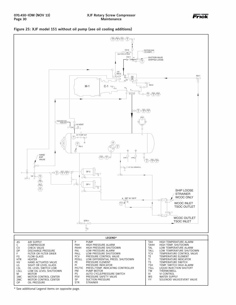
070.450-IOM (NOV 13)Page 30
XJF Rotary Screw CompressorMaintenance
Figure 25: XJF model 151 without oil pump (see oil cooling additions)
* See additional Legend items on opposite page.
LEGEND*
AS AIR SUPPLY C COMPRESSOR CV CHECK VALVE DP DISCHARGE PRESSURE F FILTER OR FILTER DRIER FG FLOW GLASS HTR HEATER HV HAND ACTUATED VALVE LG SIGHT OR LEVEL GLASS LSL OIL LEVEL SWITCH LOW LSLL LOW OIL LEVEL SHUTDOWN M MOTOR 1MC MOTOR CONTROL CENTER 2MC MOTOR CONTROL CENTER OP OIL PRESSURE
P PUMP PAH HIGH PRESSURE ALARM PAHH HIGH PRESSURE SHUTDOWN PAL LOW PRESSURE ALARM PALL LOW PRESSURE SHUTDOWN PCV PRESSURE CONTROL VALVE PDSLL LOW DIFFERENTIAL PRESS. SHUTDOWN PE PRESSURE ELEMENT PI PRESSURE INDICATOR PIC/TIC PRESS./TEMP. INDICATING CONTROLLER PM PUMP MOTOR PS AUTO CYCLE/PRESSURE SWITCH PSV PRESSURE SAFETY VALVE SP SUCTION PRESSURE STR STRAINER
TAH HIGH TEMPERATURE ALARM TAHH HIGH TEMP. SHUTDOWN TAL LOW TEMPERATURE ALARM TALL LOW TEMPERATURE SHUTDOWN TCV TEMPERATURE CONTROL VALVE TE TEMPERATURE ELEMENT TI TEMPERATURE INDICATOR TS TEMPERATURE SWITCH TSH TEMP. SWITCH HIGH ALARM TSLL LIQUID INJECTION SHUTOFF TW THERMOWELL VI VI CONTROL WS WATER SUPPLY YY SOLENOID VALVE/EVENT VALVE
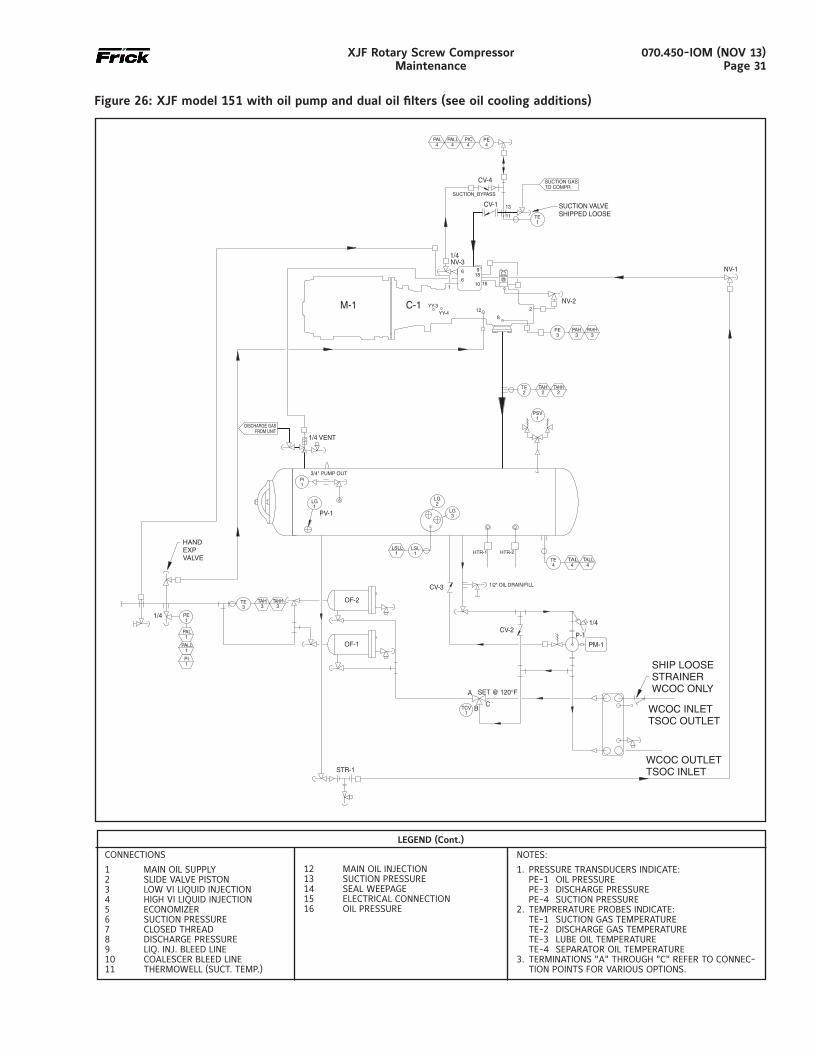
070.450-IOM (NOV 13)Page 31
XJF Rotary Screw CompressorMaintenance
Figure 26: XJF model 151 with oil pump and dual oil filters (see oil cooling additions)
LEGEND (Cont.)
CONNECTIONS
1 MAIN OIL SUPPLY 2 SLIDE VALVE PISTON 3 LOW VI LIQUID INJECTION 4 HIGH VI LIQUID INJECTION 5 ECONOMIZER 6 SUCTION PRESSURE 7 CLOSED THREAD 8 DISCHARGE PRESSURE 9 LIQ. INJ. BLEED LINE 10 COALESCER BLEED LINE 11 THERMOWELL (SUCT. TEMP.)
NOTES:
1. PRESSURE TRANSDUCERS INDICATE: PE-1 OIL PRESSURE PE-3 DISCHARGE PRESSURE PE-4 SUCTION PRESSURE 2. TEMPRERATURE PROBES INDICATE: TE-1 SUCTION GAS TEMPERATURE TE-2 DISCHARGE GAS TEMPERATURE TE-3 LUBE OIL TEMPERATURE TE-4 SEPARATOR OIL TEMPERATURE 3. TERMINATIONS "A" THROUGH "C" REFER TO CONNEC-
TION POINTS FOR VARIOUS OPTIONS.
12 MAIN OIL INJECTION 13 SUCTION PRESSURE 14 SEAL WEEPAGE 15 ELECTRICAL CONNECTION 16 OIL PRESSURE
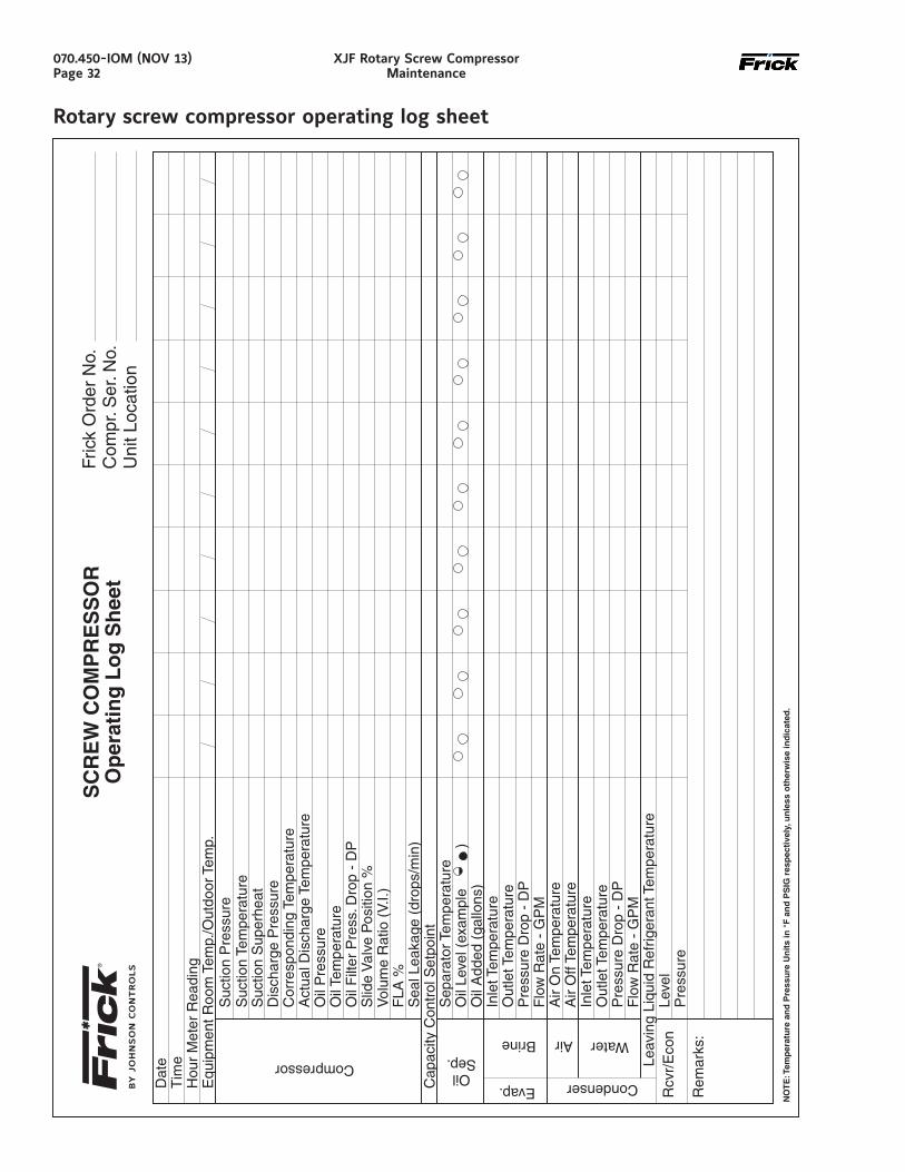
070.450-IOM (NOV 13)Page 32
XJF Rotary Screw CompressorMaintenance
Rotary screw compressor operating log sheet
Forms
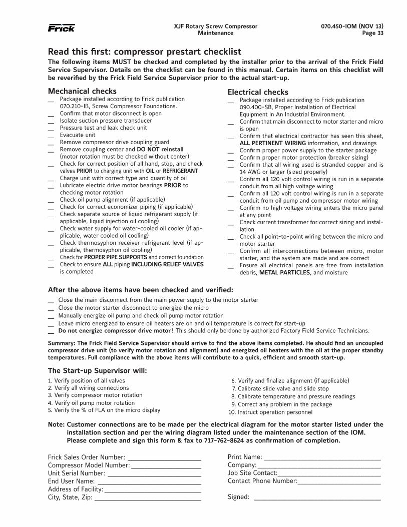
070.450-IOM (NOV 13)Page 33
XJF Rotary Screw CompressorMaintenance
Read this first: compressor prestart checklistThe following items MUST be checked and completed by the installer prior to the arrival of the Frick Field Service Supervisor. Details on the checklist can be found in this manual. Certain items on this checklist will be reverified by the Frick Field Service Supervisor prior to the actual start-up.
Mechanical checks__ Package installed according to Frick publication
070.210-IB, Screw Compressor Foundations.__ Confirm that motor disconnect is open__ Isolate suction pressure transducer__ Pressure test and leak check unit__ Evacuate unit__ Remove compressor drive coupling guard __ Remove coupling center and DO NOT reinstall (motor rotation must be checked without center)__ Check for correct position of all hand, stop, and check
valves PRIOR to charging unit with OIL or REFRIGERANT__ Charge unit with correct type and quantity of oil__ Lubricate electric drive motor bearings PRIOR to
checking motor rotation__ Check oil pump alignment (if applicable)__ Check for correct economizer piping (if applicable)__ Check separate source of liquid refrigerant supply (if
applicable, liquid injection oil cooling)__ Check water supply for water-cooled oil cooler (if ap-
plicable, water cooled oil cooling)__ Check thermosyphon receiver refrigerant level (if ap-
plicable, thermosyphon oil cooling)__ Check for PROPER PIPE SUPPORTS and correct foundation__ Check to ensure ALL piping INCLUDING RELIEF VALVES
is completed
Electrical checks__ Package installed according to Frick publication
090.400-SB, Proper Installation of Electrical Equipment In An Industrial Environment.
__ Confirm that main disconnect to motor starter and micro is open
__ Confirm that electrical contractor has seen this sheet, ALL PERTINENT WIRING information, and drawings
__ Confirm proper power supply to the starter package__ Confirm proper motor protection (breaker sizing)__ Confirm that all wiring used is stranded copper and is
14 AWG or larger (sized properly) __ Confirm all 120 volt control wiring is run in a separate
conduit from all high voltage wiring __ Confirm all 120 volt control wiring is run in a separate
conduit from oil pump and compressor motor wiring __ Confirm no high voltage wiring enters the micro panel
at any point __ Check current transformer for correct sizing and instal-
lation __ Check all point-to-point wiring between the micro and
motor starter __ Confirm all interconnections between micro, motor
starter, and the system are made and are correct__ Ensure all electrical panels are free from installation
debris, METAL PARTICLES, and moisture
After the above items have been checked and verified:__ Close the main disconnect from the main power supply to the motor starter__ Close the motor starter disconnect to energize the micro__ Manually energize oil pump and check oil pump motor rotation __ Leave micro energized to ensure oil heaters are on and oil temperature is correct for start-up __ Do not energize compressor drive motor ! This should only be done by authorized Factory Field Service Technicians.
Summary: The Frick Field Service Supervisor should arrive to find the above items completed. He should find an uncoupled compressor drive unit (to verify motor rotation and alignment) and energized oil heaters with the oil at the proper standby temperatures. Full compliance with the above items will contribute to a quick, efficient and smooth start-up.
The Start-up Supervisor will:1. Verify position of all valves 2. Verify all wiring connections 3. Verify compressor motor rotation 4. Verify oil pump motor rotation 5. Verify the % of FLA on the micro display
6. Verify and finalize alignment (if applicable) 7. Calibrate slide valve and slide stop 8. Calibrate temperature and pressure readings 9. Correct any problem in the package 10. Instruct operation personnel
Note: Customer connections are to be made per the electrical diagram for the motor starter listed under the installation section and per the wiring diagram listed under the maintenance section of the IOM.Please complete and sign this form & fax to 717-762-8624 as confirmation of completion.
Frick Sales Order Number: ______________________Compressor Model Number: _____________________Unit Serial Number: ____________________________End User Name: _______________________________Address of Facility: _____________________________City, State, Zip: ________________________________
Print Name: ___________________________________Company: _____________________________________Job Site Contact: _______________________________Contact Phone Number:_________________________
Signed: ______________________________________
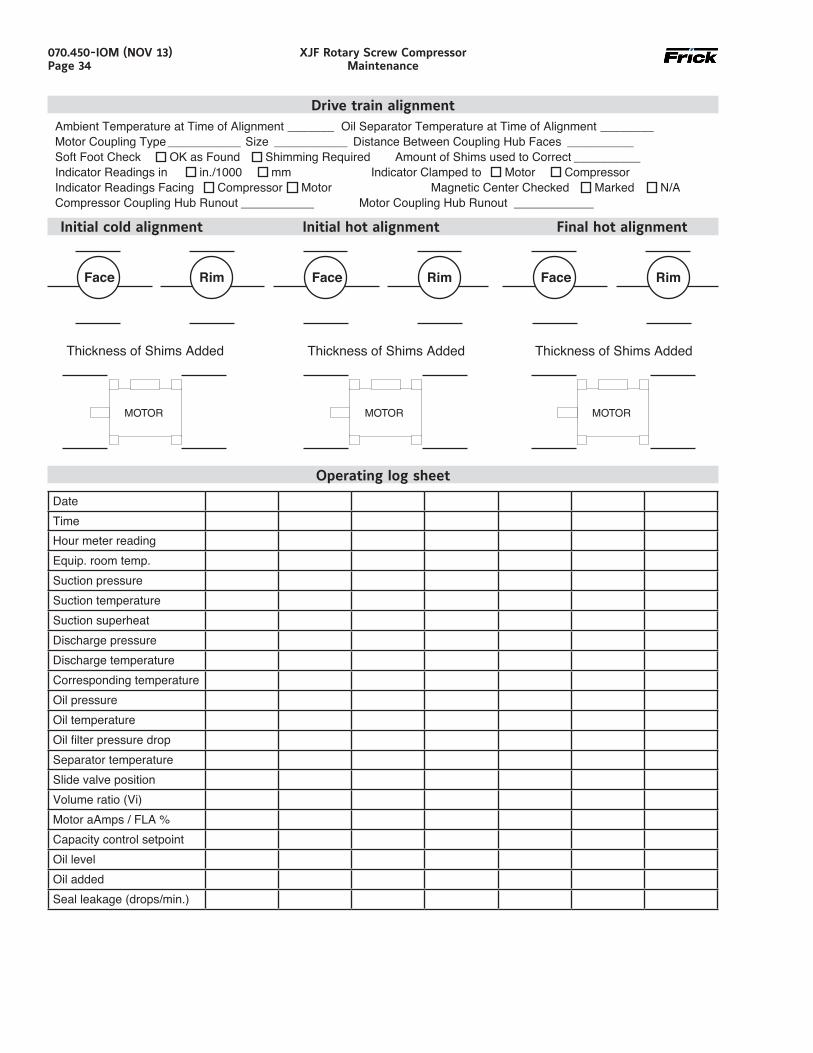
070.450-IOM (NOV 13)Page 34
XJF Rotary Screw CompressorMaintenance
Drive train alignmentAmbient Temperature at Time of Alignment _______ Oil Separator Temperature at Time of Alignment ________Motor Coupling Type ___________ Size ___________ Distance Between Coupling Hub Faces __________Soft Foot Check OK as Found Shimming Required Amount of Shims used to Correct __________Indicator Readings in in./1000 mm Indicator Clamped to Motor CompressorIndicator Readings Facing Compressor Motor Magnetic Center Checked Marked N/ACompressor Coupling Hub Runout ___________ Motor Coupling Hub Runout ____________
Initial cold alignment Initial hot alignment Final hot alignment
Operating log sheet
DateTimeHour meter readingEquip. room temp.Suction pressureSuction temperatureSuction superheatDischarge pressureDischarge temperatureCorresponding temperatureOil pressureOil temperatureOil filter pressure dropSeparator temperatureSlide valve positionVolume ratio (Vi)Motor aAmps / FLA %Capacity control setpointOil levelOil addedSeal leakage (drops/min.)
Face Rim
Thickness of Shims Added
Face Rim
Thickness of Shims Added
Face Rim
Thickness of Shims Added
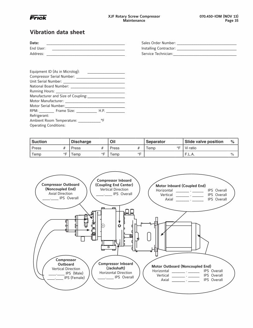
070.450-IOM (NOV 13)Page 35
XJF Rotary Screw CompressorMaintenance
Date: __________________________________________ Sales Order Number: ________________________________
End User: _______________________________________ Installing Contractor: ________________________________
Address: __________________________________________ Service Technician: __________________________________
Equipment ID (As in Microlog): ____________________Compressor Serial Number: __________________________Unit Serial Number: _________________________________National Board Number: _____________________________Running Hours: _____________________________________Manufacturer and Size of Coupling: ____________________Motor Manufacturer: ________________________________Motor Serial Number: ________________________________RPM: ________ Frame Size: ___________ H.P. __________Refrigerant:Ambient Room Temperature: ____________°FOperating Conditions:
Vibration data sheet
Suction Discharge Oil Separator Slide valve position %Press # Press # Press # Temp °F Vi ratioTemp °F Temp °F Temp °F F.L.A. %
Compressor Outboard(Noncoupled End)
Axial Direction____.____ IPS Overall
Compressor Inboard(Coupling End Center)
Vertical Direction____.____ IPS Overall
Motor Inboard (Coupled End) Horizontal _______ . ______ IPS Overall Vertical _______ . ______ IPS Overall Axial _______ . ______ IPS Overall
CompressorOutboard
Vertical Direction____.____ IPS (Male)
____.____ IPS (Female)
Compressor Inboard(Jackshaft)
Horizontal Direction____.____ IPS Overall
Motor Outboard (Noncoupled End) Horizontal _______ . ______ IPS Overall Vertical _______ . ______ IPS Overall Axial _______ . ______ IPS Overall
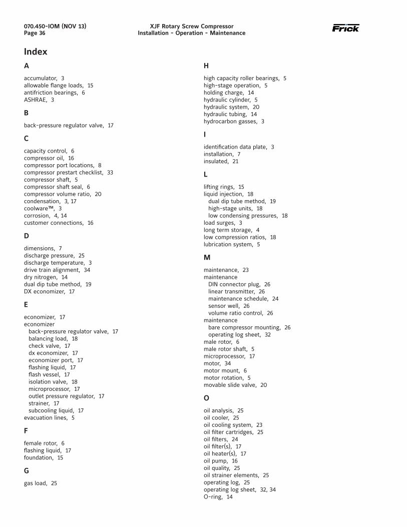
070.450-IOM (NOV 13)Page 36
XJF Rotary Screw CompressorInstallation - Operation - Maintenance
IndexA
accumulator, 3allowable flange loads, 15antifriction bearings, 6ASHRAE, 3
B
back-pressure regulator valve, 17
C
capacity control, 6compressor oil, 16compressor port locations, 8compressor prestart checklist, 33compressor shaft, 5compressor shaft seal, 6compressor volume ratio, 20condensation, 3, 17coolware™, 3corrosion, 4, 14customer connections, 16
D
dimensions, 7discharge pressure, 25discharge temperature, 3drive train alignment, 34dry nitrogen, 14dual dip tube method, 19DX economizer, 17
E
economizer, 17economizer
back-pressure regulator valve, 17balancing load, 18check valve, 17dx economizer, 17economizer port, 17flashing liquid, 17flash vessel, 17isolation valve, 18microprocessor, 17outlet pressure regulator, 17strainer, 17subcooling liquid, 17
evacuation lines, 5
F
female rotor, 6flashing liquid, 17foundation, 15
G
gas load, 25
H
high capacity roller bearings, 5high-stage operation, 5holding charge, 14hydraulic cylinder, 5hydraulic system, 20hydraulic tubing, 14hydrocarbon gasses, 3
I
identification data plate, 3installation, 7insulated, 21
L
lifting rings, 15liquid injection, 18
dual dip tube method, 19high-stage units, 18low condensing pressures, 18
load surges, 3long term storage, 4low compression ratios, 18lubrication system, 5
M
maintenance, 23maintenance
DIN connector plug, 26linear transmitter, 26maintenance schedule, 24sensor well, 26volume ratio control, 26
maintenancebare compressor mounting, 26operating log sheet, 32
male rotor, 6male rotor shaft, 5microprocessor, 17motor, 34motor mount, 6motor rotation, 5movable slide valve, 20
O
oil analysis, 25oil cooler, 25oil cooling system, 23oil filter cartridges, 25oil filters, 24oil filter(s), 17oil heater(s), 17oil pump, 16oil quality, 25oil strainer elements, 25operating log, 25operating log sheet, 32, 34O-ring, 14
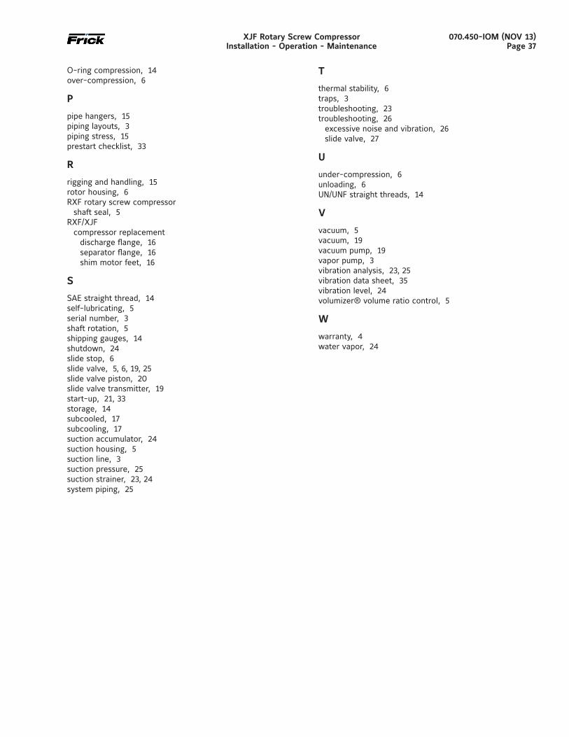
070.450-IOM (NOV 13)Page 37
XJF Rotary Screw CompressorInstallation - Operation - Maintenance
O-ring compression, 14over-compression, 6
P
pipe hangers, 15piping layouts, 3piping stress, 15prestart checklist, 33
R
rigging and handling, 15rotor housing, 6RXF rotary screw compressor
shaft seal, 5RXF/XJF
compressor replacementdischarge flange, 16separator flange, 16shim motor feet, 16
S
SAE straight thread, 14self-lubricating, 5serial number, 3shaft rotation, 5shipping gauges, 14shutdown, 24slide stop, 6slide valve, 5, 6, 19, 25slide valve piston, 20slide valve transmitter, 19start-up, 21, 33storage, 14subcooled, 17subcooling, 17suction accumulator, 24suction housing, 5suction line, 3suction pressure, 25suction strainer, 23, 24system piping, 25
T
thermal stability, 6traps, 3troubleshooting, 23troubleshooting, 26
excessive noise and vibration, 26slide valve, 27
U
under-compression, 6unloading, 6UN/UNF straight threads, 14
V
vacuum, 5vacuum, 19vacuum pump, 19vapor pump, 3vibration analysis, 23, 25vibration data sheet, 35vibration level, 24volumizer® volume ratio control, 5
W
warranty, 4water vapor, 24

Johnson Controls100 Cumberland Valley AvenueWaynesboro, PA 17268-1206 USAPhone: 717-762-2121 • FAX: 717-762-8624www.johnsoncontrols.com/Frick
Form 070.450-IOM (2013-11) rev (2022-03)Supersedes: 070.450-IOM (2013-11)
Subject to change without noticePublished in USA • 03/22 • PDF
© 2022 Johnson Controls - All Rights Reserved
March 2022 revisions
Throughout – Updated Frick and Johnson Controls logosCover – Updated web address – Updated cover statementPage 15 – Added Lifting instructions sectionPage 23 – Add warning statement in Operation and start-up
instructions – Add 2nd and 3rd warning statement in General informationPage 25 – Added note in Changing oil section


