Embed Size (px)
Citation preview

DESIGN OF AIR PRE HEATER AND ECONOMIZER
Submitted by J.SHANMUKA VENKATA GOPICHAND (101FA08133)L.SURYA TEJA (101FA08141)
Under the guidance of(Internal)N.B.PRAKASH TIRUVEEDULA ASSISTANT PROFESSOR VIGNAN UNIVERSITY
Under the guidance of(External)Mr. SREEKANTH JABADE GM AND PROJECT ENGG HARTEX RUBBER PVT LTD

CONTENTS1. Process of Air pre-heater
2. Economizer
3. Boiler basics
4. Heat Exchangers
5. Cross Flow & Compact Heat Exchangers
6. Design Calculation of Economizer
7. Design Calculation of Air pre-heater
8. Boiler Efficiency
9. Heat Balance sheet
10. Conclusion

Process of Air pre-heater• An air pre-heater (APH) is a general term to describe any device designed to heat air
before another process (for example, combustion in a boiler) with the primary objective of increasing the thermal efficiency of the process.
• There are two types of air pre-heaters for use in steam generators in thermal power stations: One is a tubular type built into the boiler flue gas ducting, and the other is a regenerative air pre-heater.
• Ambient air is forced by a fan through ducting at one end of the pre-heater tubes and at other end the heated air from inside of the tubes emerges into another set of ducting, which carries it to the boiler furnace for combustion

• There are two types of regenerative air pre-heaters: the rotating-plate regenerative air pre-heaters (RAPH) and the stationary-plate regenerative air pre-heaters.
• Rotating-plate regenerative air pre-heater

• The rotating-plate design (RAPH) consists of a central rotating-plate element installed within a casing that is divided into two (bi-sector type), three (tri-sector type) or four (quad-sector type) sectors containing seals around the element.
• In stationary-plate regenerative air pre-heaters the heating plate elements are also installed in a casing, but the heating plate elements are stationary rather than rotating.
Economizer
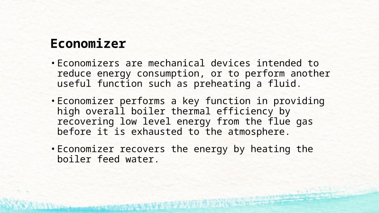
• Economizers are mechanical devices intended to reduce energy consumption, or to perform another useful function such as preheating a fluid.
• Economizer performs a key function in providing high overall boiler thermal efficiency by recovering low level energy from the flue gas before it is exhausted to the atmosphere.
• Economizer recovers the energy by heating the boiler feed water.

• It scavenge the waste heat from thermal exhaust flue gases by passing the exhaust effluent through heat transfer surfaces to transfer some of the waste heat to a process media.
• It Efficiency is in direct relationship to equipment design and stack gas velocities.
• Velocity increases through the stack as firing rate increases, which results in a decrease in contact time with the economizer heating surfaces

BOILER BASICS • The hot water or steam under pressure is then usable for transferring the heat for the
steam requirements of process industries or for power generation.
• During the combustion process, oxygen reacts with carbon, hydrogen and other elements in the fuel to produce a flame and hot combustion gases.
• As these gases are drawn through the boiler, they cool as heat is transferred to water
• The main components in a boiler system are boiler feed water heaters, deaerator, feed pump, economizer, super heater, Attemperators, condenser and condensate pump.

Heat ExchangersHeat Exchangers are classified according to their function and geometry:
Function:
Recuperative: two fluids separated by a solid wall
Evaporative: enthalpy of evaporation of one fluid is used to heat or cool the other fluid.
Regenerative: use a third material which stores/releases heat
Geometry: 1. Double Tube 2. Shell and Tube
3. Cross-flow Heat Exchangers 4. Compact Heat Exchangers

Heat Exchangers• The heat transfer rate for most heat exchangers can be calculated using the LMTD-
method (Log Mean Temperature Difference), if the inlet (T1) and outlet (T2) temperatures are known:
U = Overall heat transfer coefficient [ W/m2-oC ]
A = Effective heat transfer surface area [ m2 ]
F = Geometry correction factor
= Log mean temperature difference
FTT
TTT
12
12
/ln
TAUQ
T

Cross flow and compact heat exchangers
• Cross-flow and compact heat exchangers are used where space is limited. These aim to maximize the heat transfer surface area.
• Commonly used in gas (air) heating applications.
• The heat transfer is influenced by whether the fluids are unmixed (i.e. confined in a channel) or mixed (i.e. not confined, hence free to contact several different heat transfer surfaces).
• In a cross-flow heat exchanger the direction of fluids are perpendicular to each other.
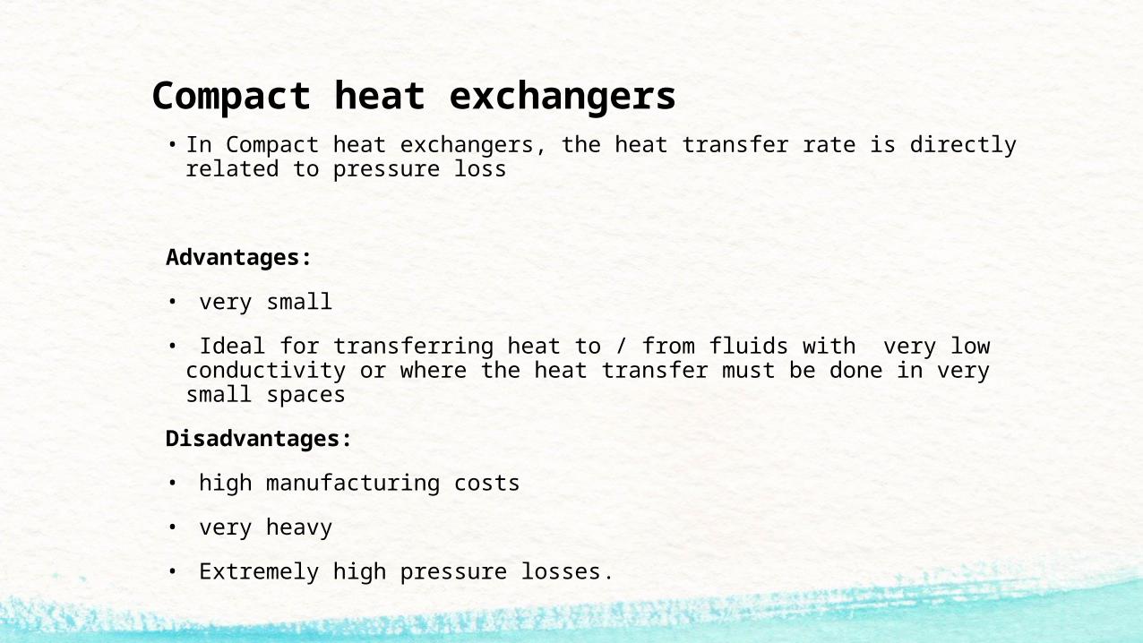
Compact heat exchangers• In Compact heat exchangers, the heat transfer rate is directly related to pressure loss
Advantages:
• very small
• Ideal for transferring heat to / from fluids with very low conductivity or where the heat transfer must be done in very small spaces
Disadvantages:
• high manufacturing costs
• very heavy
• Extremely high pressure losses.

DESIGN OF ECONOMIZERASSUMPTION:
• The properties are remains constant under steady state conditions and neglect surrounding losses. Kinetic and potential energies are neglected.
DESIGN ANALYSIS:
Heat Transfer,
Q = m x c x Δt
• Where m = mass of fluid in kg
C = specific heat of water in kj/kg oc
Δt = temperature difference

• Here m = 1800 kg/h
= 5 kg/sec
• Specific heat of water is 4.18 kj/kg oc
• Temperature difference, Δt = (70oc - 40oc) = 30oc
Q = 5 x 4.18 x 30oc
Q = 627 kW
• Heat loosing fluid
Qc = m x c x Δt
= 16 x 1.005 x (200 – 160)
= 643.2 kw.
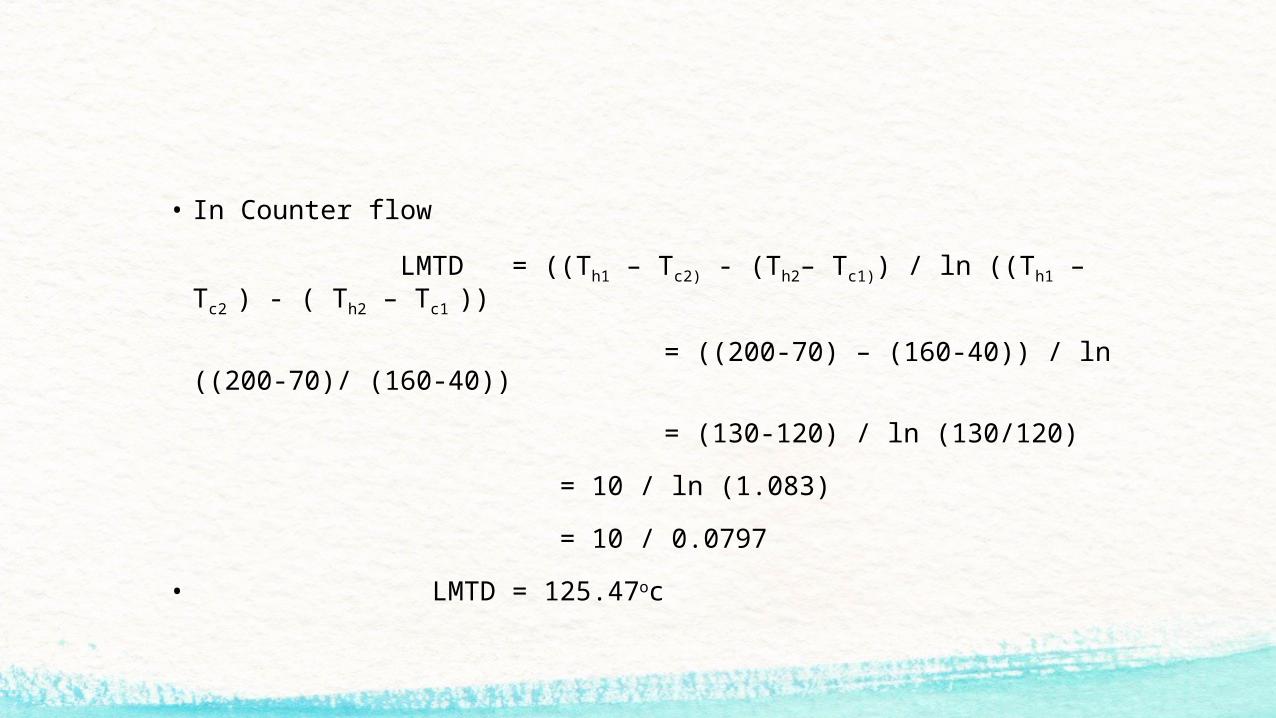
• In Counter flow
LMTD = ((Th1 – Tc2) - (Th2– Tc1)) / ln ((Th1 – Tc2 ) - ( Th2 – Tc1 ))
= ((200-70) – (160-40)) / ln ((200-70)/ (160-40))
= (130-120) / ln (130/120)
= 10 / ln (1.083)
= 10 / 0.0797
• LMTD = 125.47oc

• Actually this economizer is a cross flow economizer so, the LMTD equation becomes,
(LMTD)cross = F X (LMTD)counter
Here F = correction factor
• It is calculated by using graphical method by using dimension parameters P, Z from graph,
P= (Tc2-Tc1)/(Th1-Tc2)
P= (70-40)/ (200-70)
P= 0.2307

• Z= (Th1-Th2)/(Tc2-Tc1)
Z= (200-160)/ (70-40)
Z= 1.33
• From this values we get F = 0.98 (from graphically, pgno:31)
• So we have multiplied the counter flow LMTD with correction factor F, then we get LMTD of cross flow
(LMTD) cross = F X (LMTD) counter
= 0.98 x 125.47
= 122.96oc

• From heat transfer equation we calculate the area of economizer as follows
Q = UA ΔTm x F
Here F = Correction factor F = 0.98
A = Area of Economizer
A = (627 x 1000) / (850 x 125.4 x 0.98)
A = 6.01 m2
U = 850 w / m2 oc (from tables)
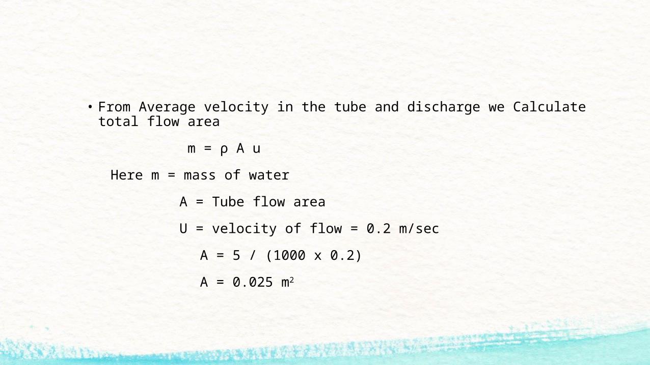
• From Average velocity in the tube and discharge we Calculate total flow area
m = ρ A u
Here m = mass of water
A = Tube flow area
U = velocity of flow = 0.2 m/sec
A = 5 / (1000 x 0.2)
A = 0.025 m2

• The above area is equal to actual cross – sectional area of tube
0.025 =n x π/4 x d2
0.025 = n x 3.14 x (0.025)2 / 4
n= 50
• From Equation 1 the area is 17.47 m2
• Then the total surface area in 2 tube pass is given below
2nπdL = 6.01
L = 6.01/(2 x 0.025 x 3.14 x 50)
L = 76 mtrs

• Each tube = 2.2 mtrs
No. of passes = 2
No. of tubes = 50

DESIGN OF AIR PRE HEATER• ASSUMPTIONS: The properties are remains constant under steady state conditions and
neglect surrounding losses. Kinetic and potential energies are neglected.
• DESIGN ANALYSIS:
Heat Transfer,
Q = m x c x Δt
Where m = mass flow rate
C = specific heat of air in kJ/kg oc
C = 1.005
Δt = temperature difference in oc

• Here m = 5 kg/sec
Specific heat of water is 4.18 kJ/kg oc
Temperature difference, Δt = (110 oc - 50 oc) = 60 oc
Q = 5 x 1.005 x 60 oc
Q = 301.5 kw
Heat loosing of fluid Q = m x c x Δt
= 5 x 1.005 x (270-200)
= 351.75 kw

• LMTD = ((Th1 – Tc2 ) - ( Th2 – Tc1 )) / ln((Th1 – Tc2 )- ( Th2 – Tc1 ))
= ((270-110) – (200-50))/ln ((270-110)/(200-50))
= (160-150)/ln (160/150)
LMTD = 156.46 oc
• Actually this Air pre-heater is a cross flow Air pre-heater so the LMTD equation Becomes,
(LMTD)cross = F X (LMTD)counter
Here F = correction factor
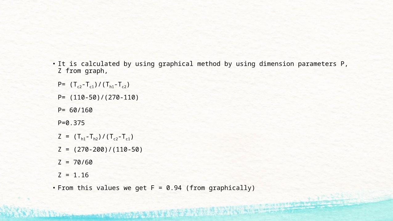
• It is calculated by using graphical method by using dimension parameters P, Z from graph,
P= (Tc2-Tc1)/(Th1-Tc2)
P= (110-50)/(270-110)
P= 60/160
P=0.375
Z = (Th1-Th2)/(Tc2-Tc1)
Z = (270-200)/(110-50)
Z = 70/60
Z = 1.16
• From this values we get F = 0.94 (from graphically)

• So we have multiplied the counter flow LMTD with correction factor F, then we get
LMTD of cross flow
(LMTD)cross = F X (LMTD)counter
= 0.94 x 156.46
= 147.07 oc
• Q = UA ΔTm x F
Where U = overall heat transfer coefficient
A = Area of Air Pre heater
F = correction factor
U = 50 w / m2 oc (As per standard tables)

• From Average velocity in the tube and discharge we Calculate total flow area
Here correction factor F = 0.94
A = q / U ΔTm x F
= (301.5X 1000) / (50 x 0.94 x 156.4)
= 43.015m2
m = ρA u
Here m = mass flow rate kg/sec
A = Tube flow area m2
U = velocity of flow = 0.2 m/sec
ρ = 1.5 kg / m3

• From continuity equation
Q = A1 X V1
5 / 1000 = 3.14 X (0.04)2 X V1
V1 = 3.98 m/sec
m = ρA u
A= m/(ρ x V1)
A=5/(1.5 x 3.98 ) = 0.83 m2
A = 0.83 m2

• The above area is equal to actual cross – sectional area of tube
0.83 m2 = n X π/4 X d2
n = 658 tubes
Length of tube for two passes
nπdL = 43.015m2
L = 43.015 / (658 x 3.14 x 0.04)
L = 0.52m
No. of tubes = 658
No. of passes = 2, Length = 0.52m

BOILER EFFICIENCY• Now we calculate the boiler efficiency of thermax boiler.
• Capacity of boiler = 6 tons/hour
• Exisisting values
• Water temperature (tw) = 35 oc
• Mass of steam (ms) = 6000kg/hr
• Mass of fuel (mf) = 1250 kg/hr
• Calorific value of husk = 3500 k.cal/kg = 14644.35kj/kg ( 1 joule = 0.239 k.cal )
• Temperature of steam (ts ) = 190 oc
• Boiler efficiency = ms (hs-hw)/mf x c.v

• Enthalpy of water at 35 oc hw =hf +x hfg
(x = 0, i.e., dryness factor, by using steam tables)
hw = 151.5 + 0 x hfg
hw = 151.5 kj/kg
• Enthalpy of steam at 190 oc
hs =hf +x hfg
hs = 8067 + (0.8 X 1977.5)
hs = 2388.7 kj/kg
• Therefore, boiler efficiency = ms (hs-hw) /(mf x c.v) x 100
= 6000(2388.7-151.5)/1250 x 14644.35) x 100
= 0.733 x 100 = 73.3%

8.1 BOILER EFFICIENCY WITH ECONOMIZER• Now introducing economizer the temperature of water increases from 35
oc TO 50 oc
now water temperature (tw) = 50 oc
And quality of steam increases up to 90 percent
• Economizer with boiler efficiency = ms(hs-hw)/mf x c.vx100
• enthalpy of water at 50 oc (hw) = hf + x hfg
= 213.7 + 0 x hfg
hw = 213.7 kj/kg
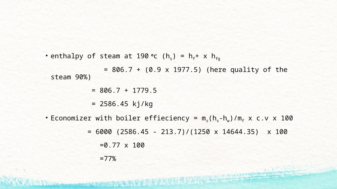
• enthalpy of steam at 190 oc (hs) = hf+ x hfg
= 806.7 + (0.9 x 1977.5) (here quality of the steam 90%)
= 806.7 + 1779.5
= 2586.45 kj/kg
• Economizer with boiler effieciency = ms(hs-hw)/mf x c.v x 100
= 6000 (2586.45 - 213.7)/(1250 x 14644.35) x 100
=0.77 x 100
=77%

8.2 BOILER EFFICIENCY WITH AIR PRE-HEATER• Now we are introducing air preheater the husk consumption reduced to
1250 kg to 1083 kg/hr
• Boiler efficiency with air preheater = MS (HS –HW)/MF X CV X 100
= 6000 (2586.45-213.7)/1083 X 14644.35) X 100
= 14236500/15859831.05 X 100
= 0.89 X 100
• Boiler efficiency with air preheater = 89%

• Water consumption per hour = 4250
• Specific heat of water = 1
ΔT = T2-T1
= 95 OC -85 OC
= 10OC
• MCPΔT = 4250 X 1 X 10 X 24 = 1020000 K.CAL
= 291.42857 KJ/KG
• Therefore 291.42857 KJ/KG Rice husk is saving

Heat Balance Sheet• Pressure of Steam = 14.2 bar
• Steam produced = 6000 kg/hour
• Coal used = 1250 kg/hour
• Moisture in Fuel = 2% of mass
• Mass of Dry Fuel gas = 9 kg of fuel
• Calorific Value of Fuel = 3500 k.cal
• Temperature of gas = 2000c
• Temperature of Boiler room = 280c
• Feed water Temperature = 500c
• Specific heat of gas = 1.005 kj/kg
• Quality of steam = 0.9%

• Heat supplied for the fuel = mf x c.v
H.S = 1 x 3500
= 3500 k.cal
• Heat supplied = 3500 k.cal
• If moisture is present then heat supplied by 1 kg of fuel = (1- mm) c.v
• Where mm is percentage of moisture
= (1-0.02) x 3500
= 3430 k.cal
= 4913.043 kj
• Heat utilized in producing Steam = ms/mf (hs-hw) →1
Where hs = hf + x hfg
= 806.7 + (0.9 x 977.5)
= 2586.45 kg
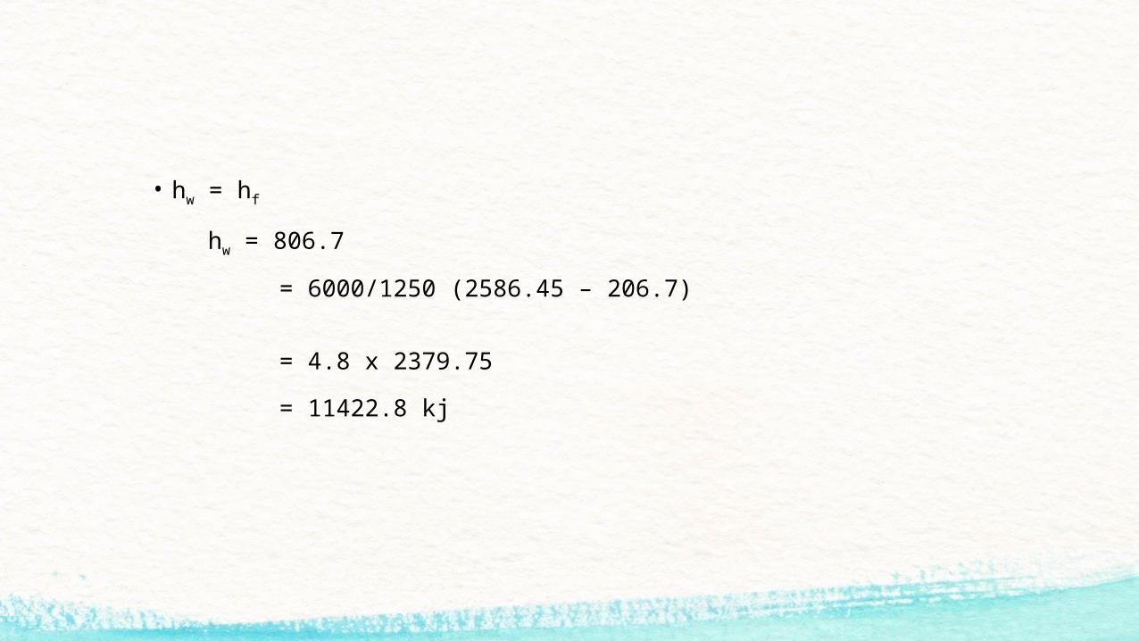
• hw = hf
hw = 806.7
= 6000/1250 (2586.45 – 206.7)
= 4.8 x 2379.75
= 11422.8 kj

• Heat carried away by the exert gases = mg cp g (Tg-Ts)
= 9 x 1.005 (2000c – 500c)
= 1356.75 kj
• Heat carried away by the moisture in the fuel = mm (2676 + 2.1 (Tg – 100) – hf)
= 0.02 (2676 + 2.1 (200 – 100) - hf)
= 0.02 (2676 + 2.1 (200 – 100) – 121.4)
= 55.292 kj

1 2 30
10
20
30
40
50
60
70
80
90
100
950
1000
1050
1100
1150
1200
1250
1300
1250 1250
1083
fuel consumption ( kg/hr )boiler efficiency (%)
Name fuel consumption ( kg/hr )
Boiler efficiency (%)
without airpreheater and economizer
1250 73.3
with economizer 1250 77
with airpreheater 1083 89

CONCLUSION• In this course of project it came to learn about the Design of Air pre-heater and
Economizer in boiler.
• By using the Air pre-heater and Economizer boiler Efficiency can be increased.
• Gas flow distribution or heat transfer into the economizer section is improved through use of guide vanes at inlet of economizer duct.
• Analysis of economizer module was carried out to predict the economizer feed water outlet temperature.
• The economizer size optimized by reducing the number of tubes of module by enhancing the heat transfer across the module.
• By installing the Air pre-heater and Economizer the total husk consumption rate is reduced and the efficiency of the boiler is also increased to 73% to 89%