Embed Size (px)
Citation preview
Date of Submission: 3rd December 2014
Md. Abdus Sobur Sikdar
Roll No: 22065
Anwar Hussen
Roll No: 22059
Husne Ara Huda
Roll No: 22060
Sonchita Mojumdar
Roll No: 22059
Ati Ranjan Das
Roll No: 22058
Submitted
By
Components of Data Communication
Mr. Sushanta Acharjee Assistant Professor
Department of CSE
Sylhet International University
Submitted To

1
CONTENTS
Components of Data Communication................................................................................. 3
Data............................................................................................................................. 3
Signal .......................................................................................................................... 3
Digital-to-digital conversion ........................................................................................... 3
Line Coding ........................................................................................................................ 4
Characteristics of line coding ......................................................................................... 4
Data element versus signal element ................................................................................ 5
Data elements are being carried: signal elements are the carriers. .............................. 5
Data Rate versus Signal Rate: ......................................................................................... 6
Bandwidth ....................................................................................................................... 6
Baseline Wandering ........................................................................................................ 6
DC Components ............................................................................................................. 7
Disadvantages: ............................................................................................................ 8
Self-Synchronization ...................................................................................................... 8
Line Coding Schemes ......................................................................................................... 9
Unipolar ........................................................................................................................ 10
Characteristic of Unipolar ......................................................................................... 10
Polar .............................................................................................................................. 11
Characteristic of Polar .............................................................................................. 11
Return to Zero (RZ) .................................................................................................. 12
Disadvantages: .......................................................................................................... 13
Advantage: ................................................................................................................ 13
Manchester Encoding ............................................................................................... 13
Advantage: ................................................................................................................ 14
Differential Manchester encoding ............................................................................ 14
Advantages: .............................................................................................................. 15
2
Bipolar schemes ............................................................................................................ 16
Alternate mark inversion (AMI) ....................................................................................... 16
Advantages: .............................................................................................................. 17
Multilevel schemes ........................................................................................................... 17
Two binary, one quaternary ...................................................................................... 17
Multilevel Schemes (2B1Q): ........................................................................................ 18
2B1Q: Two binary, one quaternary (used in D SL lines) ......................................... 19
Multilevel Schemes (8B6T): ......................................................................................... 19
Advantage: ................................................................................................................ 19
Multiline transmission .................................................................................................. 19
Questions .......................................................................................................................... 21
Solutions ........................................................................................................................... 21
Solution 1: ................................................................................................................ 21
Solution 2: ................................................................................................................ 21
Solution 3: ................................................................................................................ 21
Solution 4: ................................................................................................................ 22

3
COMPONENTS OF DATA COMMUNICATION
DATA
Analog: Continuous value data (sound, light, temperature)
Digital: Discrete value (text, integers, Symbols)
SIGNAL
Analog: Continuously varying electromagnetic wave
Digital: Series of voltage pulses (square wave)
DIGITAL-TO-DIGITAL CONVERSION
In this section we see how we can represent digital data by using digital
signals. The conversion involves three techniques: line coding, block
coding and scrambling. Line coding is always needed but block coding and
scrambling may or may not be needed

4
LINE CODING
Line coding is the process of converting digital data to digital signals. This
mean Procedure of converting binary data to a digital signal.
At the sender digital data are encoded into a digital signal, at the receiver,
the digital data are recreated by decoding the digital signal.
Figure: Line Coding and decoding
CHARACTERISTICS OF LINE CODING
There are some common characteristics discussing bellow
i. Signal level vs data level
ii. Pulse rate vs Bit rate
iii. DC components
iv. Self-synchronization
5
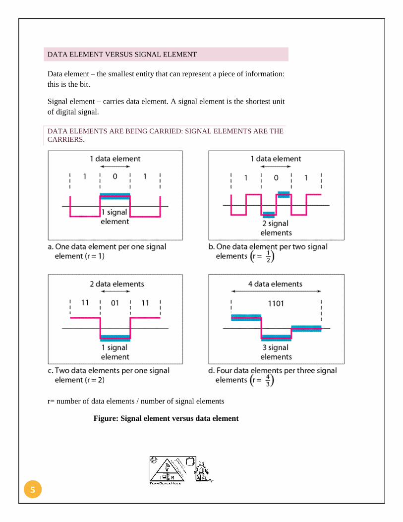
DATA ELEMENT VERSUS SIGNAL ELEMENT
Data element – the smallest entity that can represent a piece of information:
this is the bit.
Signal element – carries data element. A signal element is the shortest unit
of digital signal.
DATA ELEMENTS ARE BEING CARRIED: SIGNAL ELEMENTS ARE THE
CARRIERS.
r= number of data elements / number of signal elements
Figure: Signal element versus data element

6
DATA RATE VERSUS SIGNAL RATE:
Data rate (bit rate): the No. of data elements sent in 1s. (bps).
Signal rate (pulse rate, modulation rate or baud rate): the number of
signal elements sent in 1s. (baud).
Relationship between Data rate VS Signal rate
The baud or signal rate can be expressed as:
S = c × N × 1
𝑟 bauds
Where N is data rate
S is number of signal element, (baud) c is the case factor (worst, best & avg.) r is the ratio between data element & signal element
BANDWIDTH
a. The range of frequencies that a medium can pass is called bend
with.
b. It is the difference between the highest and lowest frequencies.
BASELINE WANDERING
a. Baseline: running average of the received signal power
b. Baseline wandering: A long sequence of 0s or 1s make baseline
wandering.

7
Amplitude 1 1 1 1
Time
Figure: Baseline wandering for 1s
Amplitude 0 0 0 0
Time
Figure: Baseline Wandering for 0s
DC COMPONENTS
a. When the voltage level in a digital signal is constant for a while, the
spectrum creates very low frequencies. These frequencies around
zero, called DC Components.
b. Constant digital signal creates low frequencies. .
c. Average amplitude of a unipolar encoded signal is nonzero.
d. This creates a direct current (DC component) shifts the zero level
that cannot travel through some media (e.g. microwave).

8
DISADVANTAGES:
i. Residual DC (Direct-Current) components or zero frequencies
are undesirable.
ii. Some systems don’t allow passage of a DC component may
distort the signal and create output errors.
iii. DC component is extra energy and is ineffective.
Figure: DC Component
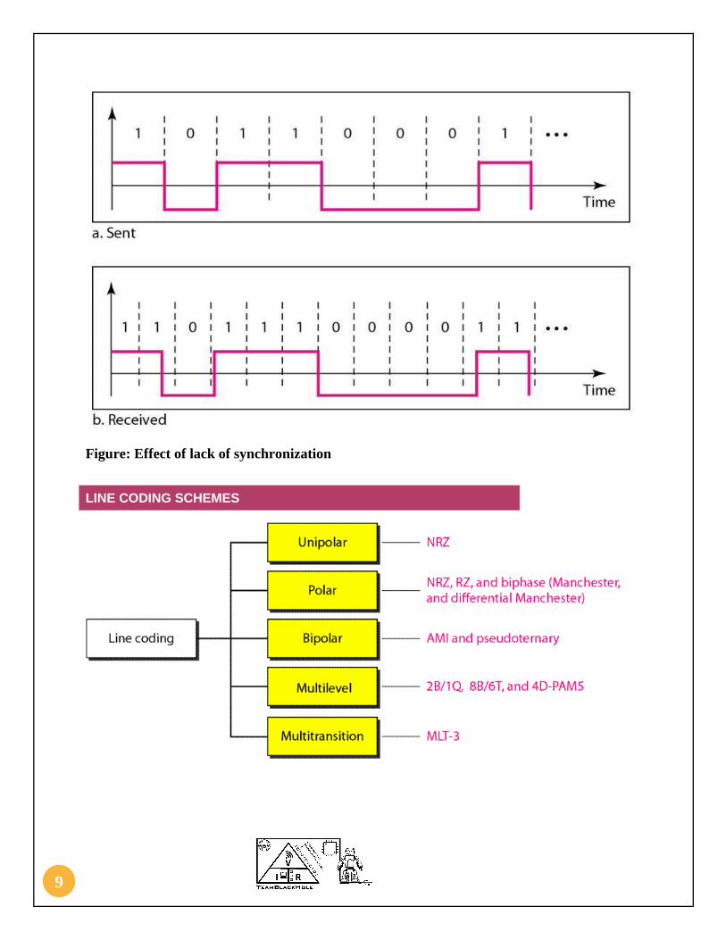
SELF-SYNCHRONIZATION
i. Receiver’s bit intervals must correspond exactly to the sender’s
bit intervals
ii. Receiver’s clock setting must match the sender’s one
iii. Self-synchronizing signal includes timing information
iv. If the receiver’s clock is out of synchronization, these alerting
points can reset the clock.
9
Figure: Effect of lack of synchronization
LINE CODING SCHEMES

10
UNIPOLAR
In unipolar scheme, all the signal levels are on one side of the time axis,
either above or below.
NRZ (None-Return-to-Zero).
In this scheme positive voltage defines by bit 1 and the zero voltage defines
by bit 0.
Figure: Unipolar encoding.
CHARACTERISTIC OF UNIPOLAR
1. The simplest and most primitive type of encoding is unipolar
encoding.
2. Typically, one voltage level stands for binary 0 and another
voltage level for binary 1.
3. Polarity refers to whether you have a positive or a negative pulse.
4. Unipolar encoding uses only one polarity, only one of the two
binary states is encoded, usually the 1.
5. Two problems with unipolar encoding: DC component and
synchronization.

11
POLAR
NRZ
• Non-return to Zero (NRZ) -- signal is always positive or negative.
• Two main types of NRZ: NRZ-L and NRZ-I
NRZ-L
• NRZ-L: signal never returns to zero voltage, and the value
during a bit time is a level voltage.
• Good for short and well- shielded transmission paths.
NRZ-I
– NRZ-I : invert on ones
– The transition between a positive and negative voltage
represents a 1 bit.
– Provides more synchronization than NRZ-L because there
is a transition for each 1 bit.
CHARACTERISTIC OF POLAR
i. In polar scheme, the voltages are on the both side of time axis.
ii. There are two popular forms of NRZ: NRZ-L and NRZ-I.
iii. In NRZ-Level (NRZ-L), a positive voltage means ‘0’ bit, while
a negative voltage means ‘1’ bit.
iv. In NRZ-Invert (NRZ-I), it is the transition between positive and
negative voltage.
v. When the bit is 0 there is no change, when the bit is 1 there is
change.

12
vi. In NRZ-L, the level of the voltage determines the value of the
bit: RS232.
vii. In NRZ-I (-M or –S), the inversion or the lack of inversion
determines the value of the bit. USB, CD, and Fast-Ethernet.
viii. NRZ-L and NRZ-I both have an average signal rate of N/2 Bd.
RETURN TO ZERO (RZ)
i. Return to zero uses three values: positive, negative and zero. In
RZ, the signal changes not between bits but during (middle of )
each bit.
ii. Bit 1 is represented by positive-to-zero and a 0 bit by negative-
to-zero.
iii. Tries to solve the problem of losing synchronization due to long
strings of consecutive 1s or 0s.
iv. Signal change during each bit promotes synchronization.
Positive voltage=1
Negative voltage=0
v. Signal returns to zero halfway through the bit interval.

13
Figure: RZ scheme
DISADVANTAGES:
i. the main disadvantage of RZ is that it requires two signal changes
to encode one bit and therefor occupies more bandwidth.
ii. RZ systems are less data-efficient than NRZ signalling methods.
iii. Signal bandwidth is cut in half because half of the bandwidth is
used to return the signal to zero volts, during which no data is
transmitted.
ADVANTAGE:
i. No DC component.
ii. It solves the synchronization problem of NRZ.
iii. RZ control logic chips are simpler.
iv. RZ control logic chips are cheaper.
v. The transmitting computer needs only one electrical circuit to
transmit the data (one pair of wires).
MANCHESTER ENCODING
i. The idea of RZ and the idea of NRZ-L are combined into the
Manchester scheme.
ii. A negative-to-positive transition represents 1 and a positive-to-
negative transition represents 0.

14
Figure: Manchester encoding
ADVANTAGE:
i. The Manchester schema overcomes baseline wandering and
DC component problem of NRZ-L
ii. There is no dc component , because each bit has a positive
and negative voltage contribution.
iii. This code is self-clocking.
iv. Provides a transition for every bit in the middle of the bit
cell. This transition is used only to provide clocking.
v. Positive to negative transition for a "0" bit
vi. Negative to positive transition for a "1" bit
vii. Residual DC component is eliminated by having both
polarities for every bit.
viii. This scheme is used in Ethernet and IEEE 802.3
compliant LANs
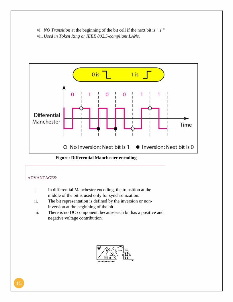
DIFFERENTIAL MANCHESTER ENCODING
i. In difference Manchester is the combines of ideas of rz and nrz-1.
ii. If the next bit is 0 there is transition, if the bit is 1 there is none.
iii. Code is self-clocking
iv. Transition for every bit in the middle of the bit cell
v. Transition at the beginning of the bit cell if the next bit is " 0 "
15
vi. NO Transition at the beginning of the bit cell if the next bit is " 1 "
vii. Used in Token Ring or IEEE 802.5-compliant LANs.
Figure: Differential Manchester encoding
ADVANTAGES:
i. In differential Manchester encoding, the transition at the
middle of the bit is used only for synchronization.
ii. The bit representation is defined by the inversion or non-
inversion at the beginning of the bit.
iii. There is no DC component, because each bit has a positive and
negative voltage contribution.

16
BIPOLAR SCHEMES
i. In bipolar encoding, we use three levels : positive, zero and negative
ii. Bipolar schemes : AMI and pseudoternary
iii. It is a better alternative to NRZ.
iv. Has no DC component or baseline wandering.
v. Has no self-synchronization because long runs of “0”s results in no
signal transitions.
vi. No error detection.
ALTERNATE MARK INVERSION (AMI)
i. A natural zero voltage represented binary 0. Binary 1s
represented by alternating positive and negative voltage.
ii. In bipolar encoding, we use three levels: positive, zero, and
negative.
iii. Pseudoternary: – 1 represented by absence of line signal – 0
represented by alternating positive and negative
Pseudoternary

17
i. In pseudoternary the bit 1 is encoded as a zero voltage and the
bit o is encoded as alternating positive and negative voltage.
Figure: Bipolar schemes: AMI and Pseudoternary
ADVANTAGES:
i. No DC component
ii. Loss of synchronization for long sequence 0 in pseudoternary
MULTILEVEL SCHEMES
i. The desire to increase the data speed or decrease the required
bandwidth has resulted in the creation of many scheme
ii. The goal is to increase the number of bits per baud by encoding a
pattern of m data elements into a pattern of n signal elements.
TWO BINARY, ONE QUATERNARY
i. With the 2B1Q code to binary signal are converted into a
quarternaeres signal. This known 4 difference condition
(00,01,11, 10)

18
Figure: Multilevel: 2B1Q scheme
MULTILEVEL SCHEMES (2B1Q):
In mBnL schemes, a pattern of m data elements is encoded as a pattern of n
signal elements in which 2m ≤ Ln.
We use the notation mBnL, where
m is the length of the binary pattern,
B represents binary data,
n represents the length of the signal pattern and

19
L the number of levels in the signaling.
L = B for 2 binary,
L = T for 3 ternary, and
L = Q for 4 quaternary.
2B1Q: TWO BINARY, ONE QUATERNARY (USED IN D SL LINES)
Four levels of voltage signal, each encode s 2 bits. No self - synch for long
same double bits. Required bandwidth = B ave = N / 4 Pros.: simple, typical
codes balance voltage and lesser baseline wandering. Cons.: long sequences
of zeros, or "01" will have constant DC output.
MULTILEVEL SCHEMES (8B6T):
ADVANTAGE:
We can send more than one data with a signal. It saves bandwidth.
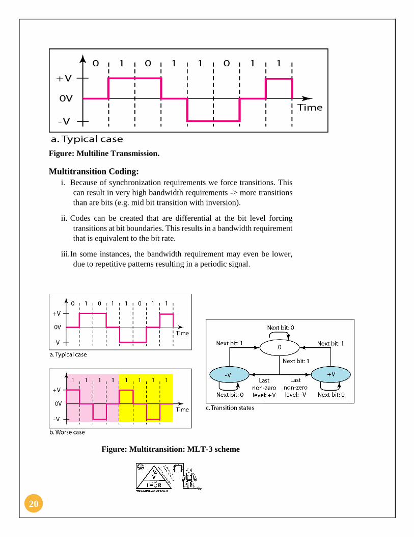
MULTILINE TRANSMISSION
i. The multiline transmission three level scheme uses three level (+v ,
0 and v ) and three transmission rules to move between the levels:
ii. If the next bit is 0, there is no transition.
iii. If next bit is 1 and the current level is not 0, the next level is 0.
iv. If the next bits is 1, and the current level is 0, the next level is opposite
of the last nonzero level.
20
Figure: Multiline Transmission.
Multitransition Coding:
i. Because of synchronization requirements we force transitions. This
can result in very high bandwidth requirements -> more transitions
than are bits (e.g. mid bit transition with inversion).
ii. Codes can be created that are differential at the bit level forcing
transitions at bit boundaries. This results in a bandwidth requirement
that is equivalent to the bit rate.
iii. In some instances, the bandwidth requirement may even be lower,
due to repetitive patterns resulting in a periodic signal.
Figure: Multitransition: MLT-3 scheme

21
QUESTIONS
1. The bit rate of a signal is 3000. If each signal unit carries 6 bits,
what is the baud rate?
2. A signal is carrying data in which one data element is encoded as
one signal element ( r = 1). If the bit rate is 100 kbps, what is the
average value of the baud rate if c is between 0 and 1?
3. What is line coding? Write down Schemas of line coding?
4. Write down about Manchester Encoding? Also explain its
advantages?
SOLUTIONS
SOLUTION 1:
Baud rate = 3000 / 6 = 500 baud/s
SOLUTION 2:
We assume that the average value of c is 1/2 . The baud rate is then
SOLUTION 3:
Line Coding: Line coding is the process of converting digital data to digital
signals. This mean Procedure of converting binary data to a digital signal.
Line Coding Schema are given below.

22
SOLUTION 4:
The idea of RZ and the idea of NRZ-L are combined into the Manchester
scheme.
A negative-to-positive transition represents 1 and a positive-to-negative
transition represents 0.
Figure: Manchester encoding
Advantages of Manchester encoding are given below.

23
a. The Manchester schema overcomes baseline wandering and
DC component problem of NRZ-L
b. There is no dc component, because each bit has a positive
and negative voltage contribution.
c. This code is self-clocking.
d. Provides a transition for every bit in the middle of the bit
cell. This transition is used only to provide clocking.
e. Positive to negative transition for a "0" bit
f. Negative to positive transition for a "1" bit
g. Residual DC component is eliminated by having both
polarities for every bit.
h. This scheme is used in Ethernet and IEEE 802.3 compliant
LANs