Embed Size (px)
Citation preview
Installer’s Handbook
LM80031 Issue H

Stratos‐Nano Installers Handbook LM80031 Issue H Page 2 of 16
Index
Introduction Page 3
Outside the Detector Page 4
Inside the Detector Page 5
Installation: Mechanical Page 6
Installation: Printable A4 Drill Template Page 7
Installation: Electrical Page 8
Installation: Sampling Pipe Page 9
Configuration Page 10
Commissioning Page 11
Maintenance Page 12
Troubleshooting Page 13
Optional: Communications Card Page 14
Technical Data & EN54-20 Compliance Page 15/16
0832 Kidde Products Limited
Unit 2 Blair Way
Dawdon
City: Seaham, County Durham
SR7 7PP UK
09
0832‐CPD‐1312
EN 54‐20:2006
Aspirating smoke detectors
for fire detection and fire alarm
systems for buildings
Class A, B and C
Stratos‐Nano Installers Handbook LM80031 Issue H Page 3 of 16
Introduction
This aspirating smoke detector is designed to provide reliable performance in a variety of environment and to ensure that installation and commissioning are as simple as possible. An aspirating smoke detector uses a fan to draw samples of air from a network of pipes with sampling holes positioned as if they were point smoke detectors.
The detector incorporates a patented artificial intelligence system which allows the detector to adjust itself to the optimum sensitivity for any environment.
The artificial intelligence system also monitors the detector chamber and air filter, and automatically compensates for contamination. This provides a stable response and signals a fault if the contamination reaches a level that cannot be compensated for.
________________________________________________________________________
This smoke detector is Class III as defined in EN60950. It is designed to operate from Safety Extra Low Voltages and does not generate any hazardous voltages.
________________________________________________________________________
If this detector is to form part of an approved fire detection system, its power must be supplied from a certified power supply (typically EN 54-4).
________________________________________________________________________
In order for the installation to conform to EN 54-20, pipes must conform at least to EN 61386-1 Class 1131.
________________________________________________________________________
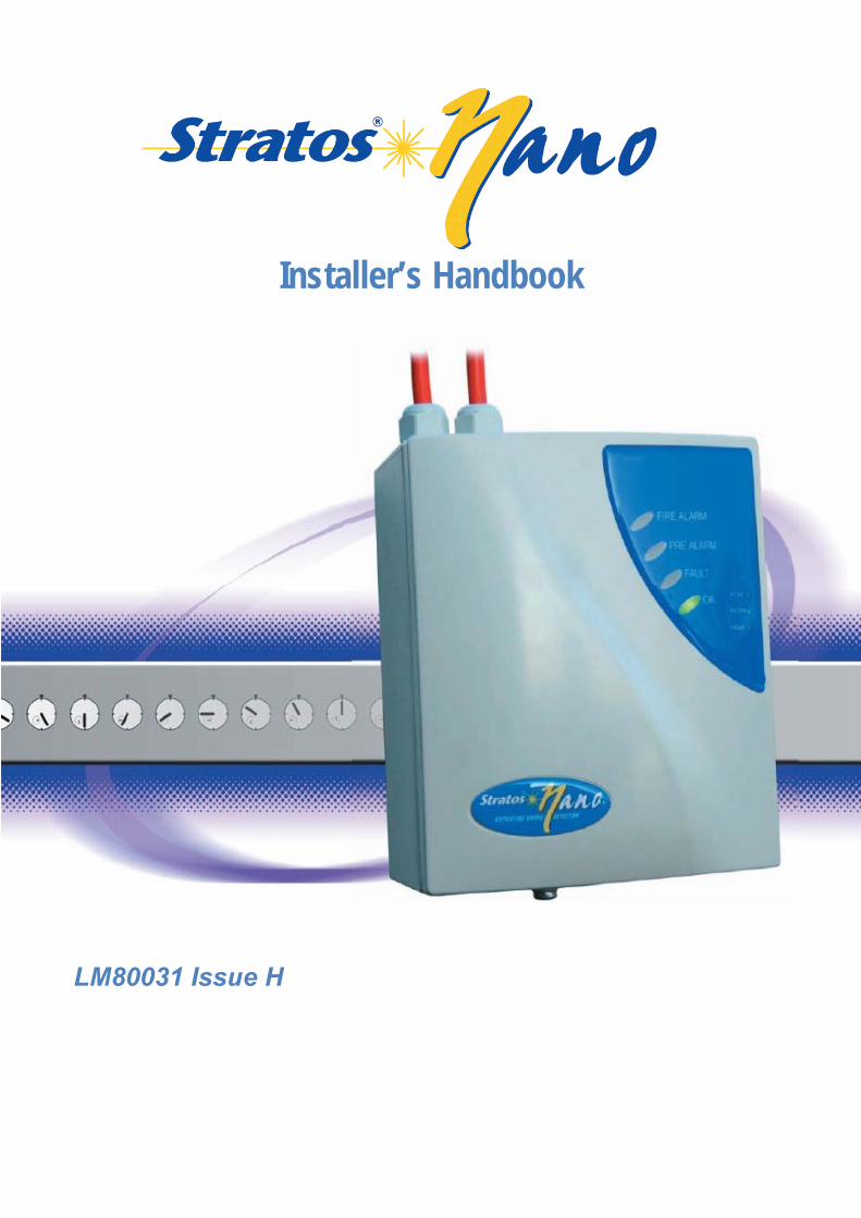
Please note that printed circuit boards are static sensitive and must not be handled without taking proper static precautions.
________________________________________________________________________
The detector is a Class 1 laser product as defined in IEC 60825-1. This unit incorporates a Class 3B embedded laser which must not be removed from the detector, as retinal damage may occur if the beam enters the eye.
________________________________________________________________________
Every care has been taken to ensure that the detector is as easy to install as possible by trained fire alarm engineers. In case of difficulty, please contact the Help Line in the first instance to ensure trouble free installation and operation.
HELP LINE: +31(0)20 161311
The manufacturer takes no responsibility for damage or injury occasioned as a result of failing to install or operate or maintain the equipment in accordance with these instructions and other good practices.
Stratos‐Nano Installers Handbook LM80031 Issue H Page 4 of 16
Outside the Detector
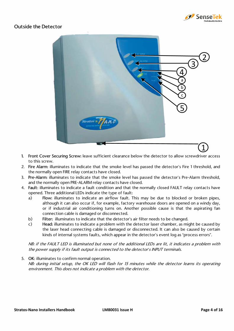
1. Front Cover Securing Screw: leave sufficient clearance below the detector to allow screwdriver accessto this screw.
2. Fire Alarm: illuminates to indicate that the smoke level has passed the detector’s Fire 1 threshold, andthe normally open FIRE relay contacts have closed.
3. Pre-Alarm: illuminates to indicate that the smoke level has passed the detector’s Pre-Alarm threshold,and the normally open PRE-ALARM relay contacts have closed.
4. Fault: illuminates to indicate a fault condition and that the normally closed FAULT relay contacts haveopened. Three additional LEDs indicate the type of fault:a) Flow: illuminates to indicate an airflow fault. This may be due to blocked or broken pipes,
although it can also occur if, for example, factory warehouse doors are opened on a windy day,or if industrial air conditioning turns on. Another possible cause is that the aspirating fanconnection cable is damaged or disconnected.
b) Filter: illuminates to indicate that the detector’s air filter needs to be changed.c) Head: illuminates to indicate a problem with the detector laser chamber, as might be caused by
the laser head connecting cable is damaged or disconnected. It can also be caused by certainkinds of internal systems faults, which appear in the detector’s event log as “process errors”.
NB: if the FAULT LED is illuminated but none of the additional LEDs are lit, it indicates a problem with the power supply if its fault output is connected to the detector’s INPUT terminals.
5. OK: illuminates to confirm normal operation.NB: during initial setup, the OK LED will flash for 15 minutes while the detector learns its operatingenvironment. This does not indicate a problem with the detector.
32
4 a
c
1
b
5
Stratos‐Nano Installers Handbook LM80031 Issue H Page 5 of 16
Inside the Detector
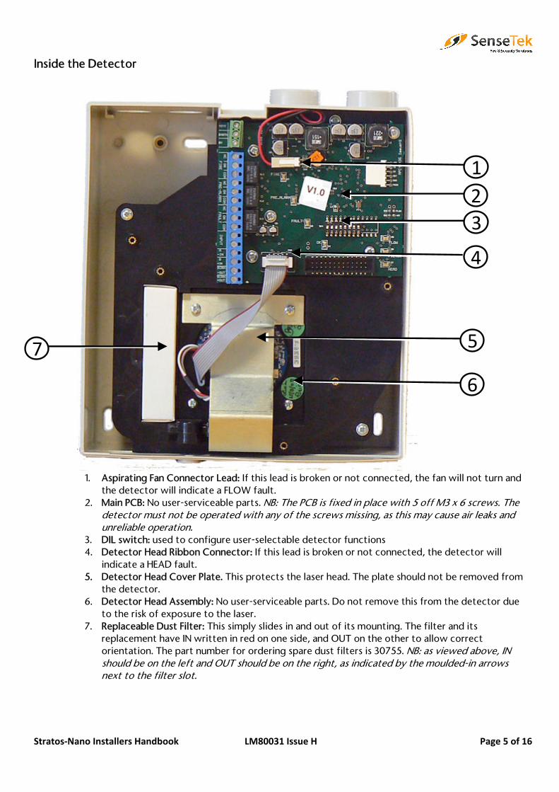
1. Aspirating Fan Connector Lead: If this lead is broken or not connected, the fan will not turn andthe detector will indicate a FLOW fault.
2. Main PCB: No user-serviceable parts. NB: The PCB is fixed in place with 5 off M3 x 6 screws. The detector must not be operated with any of the screws missing, as this may cause air leaks and unreliable operation.
3. DIL switch: used to configure user-selectable detector functions4. Detector Head Ribbon Connector: If this lead is broken or not connected, the detector will
indicate a HEAD fault.5. Detector Head Cover Plate. This protects the laser head. The plate should not be removed from
the detector.6. Detector Head Assembly: No user-serviceable parts. Do not remove this from the detector due
to the risk of exposure to the laser.7. Replaceable Dust Filter: This simply slides in and out of its mounting. The filter and its
replacement have IN written in red on one side, and OUT on the other to allow correctorientation. The part number for ordering spare dust filters is 30755. NB: as viewed above, IN should be on the left and OUT should be on the right, as indicated by the moulded-in arrows next to the filter slot.
21
4
5
6
7
3
Stratos‐Nano Installers Handbook LM80031 Issue H Page 6 of 16
Installation: Mechanical
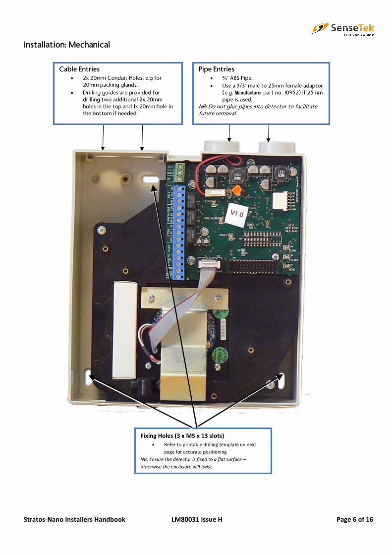
Fixing Holes (3 x M5 x 13 slots)• Refer to printable drilling template on next
page for accurate positioning NB: Ensure the detector is fixed to a flat surface – otherwise the enclosure will twist.
Cable Entries • 2x 20mm Conduit Holes, e.g for
20mm packing glands.• Drilling guides are provided for
drilling two additional 2x 20mmholes in the top and 1x 20mm hole inthe bottom if needed.
Pipe Entries• ¾” ABS Pipe.• Use a 3/3” male to 25mm female adaptor
(e.g. Manufacturer part no. 10952) if 25mmpipe is used.
NB: Do not glue pipes into detector to facilitate future removal.
Stratos‐Nano Installers Handbook LM80031 Issue H Page 7 of 16
Installation: Printable A4 Drilling Template
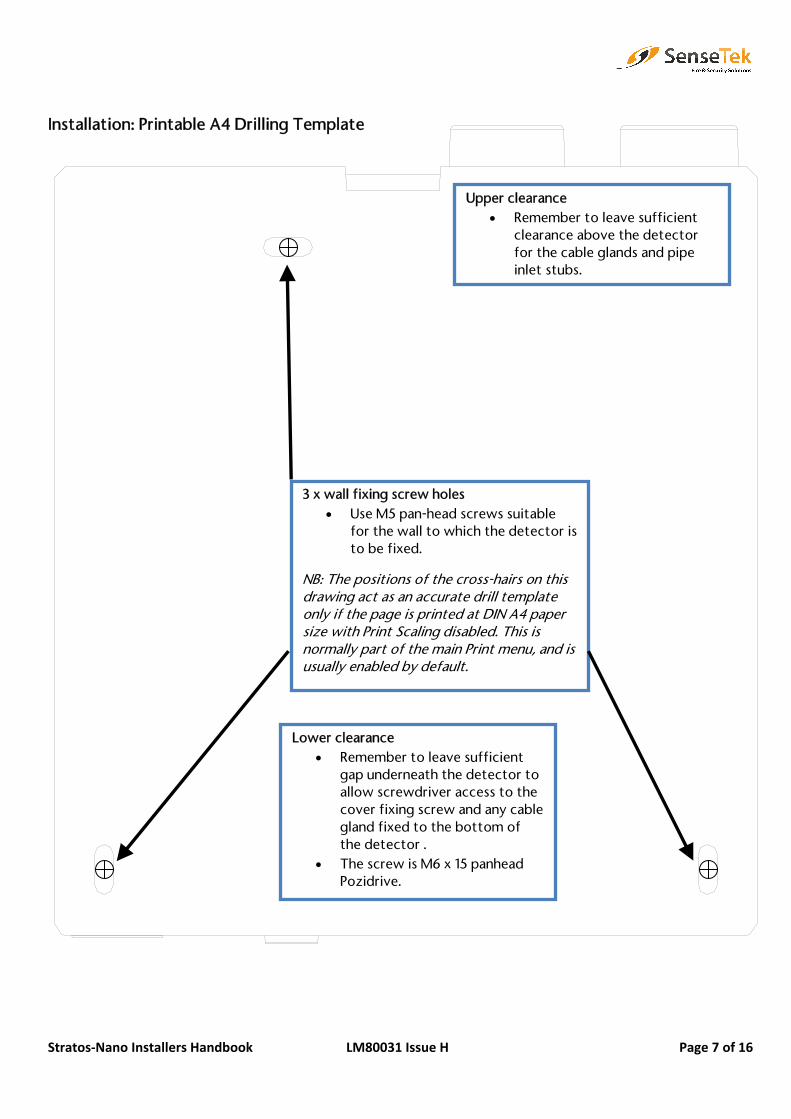
Lower clearance• Remember to leave sufficient
gap underneath the detector toallow screwdriver access to thecover fixing screw and any cablegland fixed to the bottom ofthe detector .
• The screw is M6 x 15 panheadPozidrive.
Upper clearance • Remember to leave sufficient
clearance above the detectorfor the cable glands and pipeinlet stubs.
3 x wall fixing screw holes• Use M5 pan-head screws suitable
for the wall to which the detector isto be fixed.
NB: The positions of the cross-hairs on this drawing act as an accurate drill template only if the page is printed at DIN A4 paper size with Print Scaling disabled. This is normally part of the main Print menu, and is usually enabled by default.
Stratos‐Nano Installers Handbook LM80031 Issue H Page 8 of 16
+24V
EARTH
0V
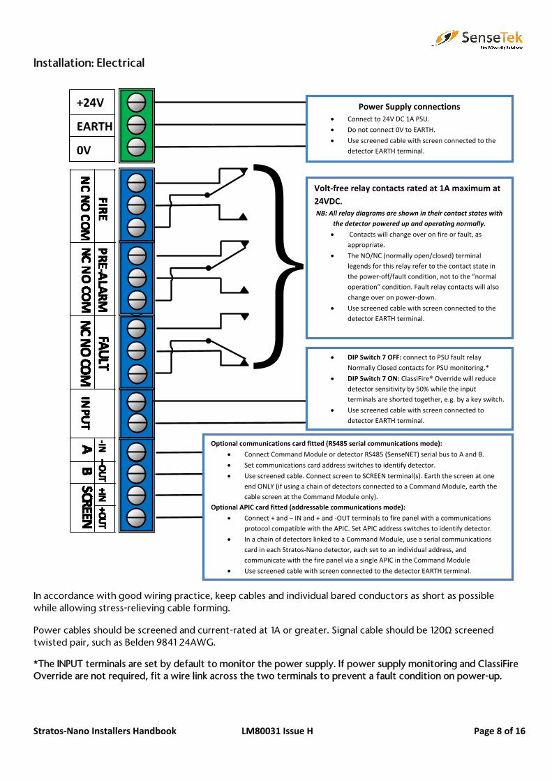
Installation: Electrical
In accordance with good wiring practice, keep cables and individual bared conductors as short as possible while allowing stress-relieving cable forming.
Power cables should be screened and current-rated at 1A or greater. Signal cable should be 120Ω screened twisted pair, such as Belden 9841 24AWG.
*The INPUT terminals are set by default to monitor the power supply. If power supply monitoring and ClassiFireOverride are not required, fit a wire link across the two terminals to prevent a fault condition on power-up.
Volt‐free relay contacts rated at 1A maximum at 24VDC. NB: All relay diagrams are shown in their contact states with
the detector powered up and operating normally.
• Contacts will change over on fire or fault, as appropriate.
• The NO/NC (normally open/closed) terminal legends for this relay refer to the contact state in the power‐off/fault condition, not to the “normal operation” condition. Fault relay contacts will alsochange over on power‐down.
• Use screened cable with screen connected to the detector EARTH terminal.
Power Supply connections• Connect to 24V DC 1A PSU.
• Do not connect 0V to EARTH.
• Use screened cable with screen connected to the detector EARTH terminal.
• DIP Switch 7 OFF: connect to PSU fault relay Normally Closed contacts for PSU monitoring.*
• DIP Switch 7 ON: ClassiFire® Override will reduce detector sensitivity by 50% while the input terminals are shorted together, e.g. by a key switch.
• Use screened cable with screen connected to detector EARTH terminal.
Optional communications card fitted (RS485 serial communications mode):
• Connect Command Module or detector RS485 (SenseNET) serial bus to A and B.
• Set communications card address switches to identify detector.
• Use screened cable. Connect screen to SCREEN terminal(s). Earth the screen at one end ONLY (if using a chain of detectors connected to a Command Module, earth the cable screen at the Command Module only).
Optional APIC card fitted (addressable communications mode):
• Connect + and – IN and + and ‐OUT terminals to fire panel with a communications protocol compatible with the APIC. Set APIC address switches to identify detector.
• In a chain of detectors linked to a Command Module, use a serial communicationscard in each Stratos‐Nano detector, each set to an individual address, and communicate with the fire panel via a single APIC in the Command Module
• Use screened cable with screen connected to the detector EARTH terminal.
Stratos‐Nano Installers Handbook LM80031 Issue H Page 9 of 16
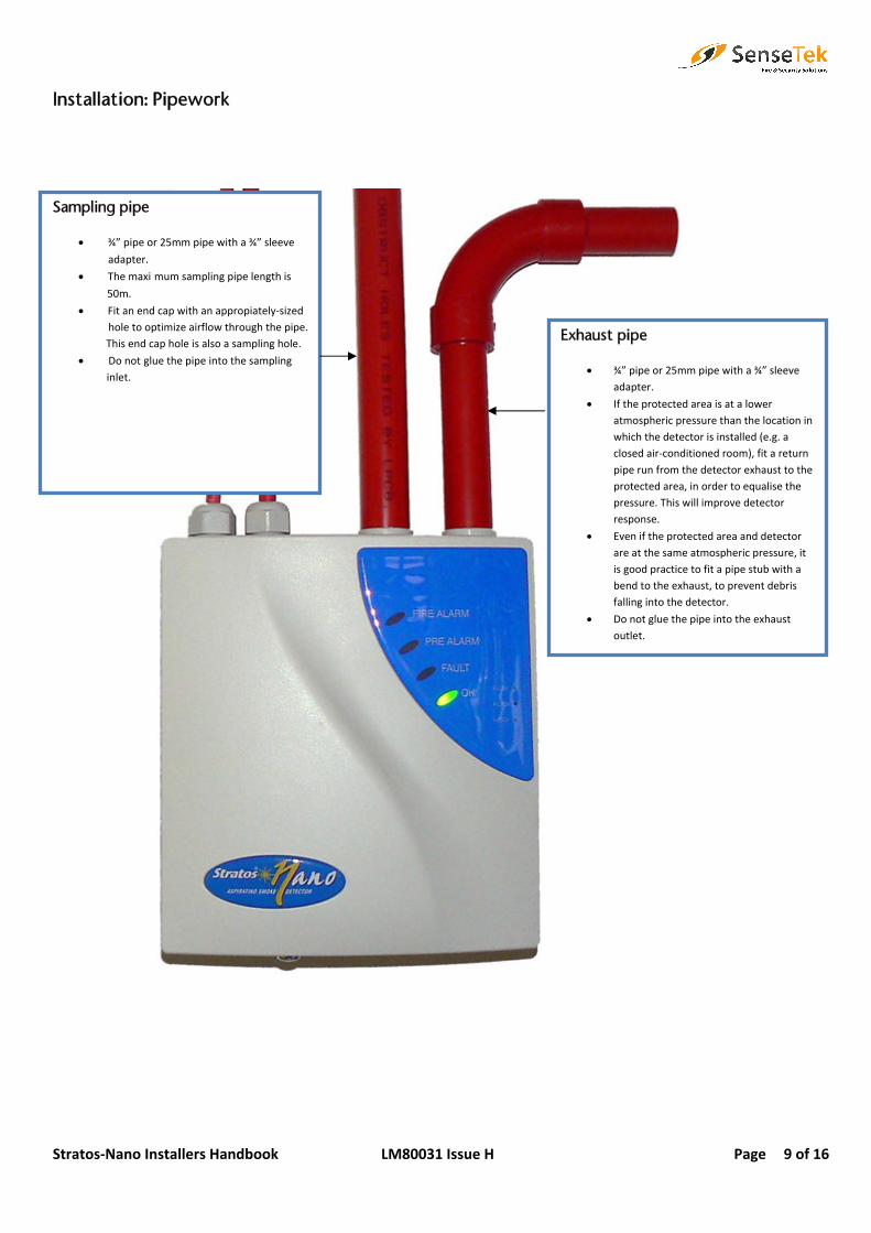
Installation: Pipework
Exhaust pipe
• ¾” pipe or 25mm pipe with a ¾” sleeve adapter.
• If the protected area is at a lower atmospheric pressure than the location in which the detector is installed (e.g. a closed air‐conditioned room), fit a return pipe run from the detector exhaust to the protected area, in order to equalise the pressure. This will improve detector response.
• Even if the protected area and detector are at the same atmospheric pressure, itis good practice to fit a pipe stub with a bend to the exhaust, to prevent debris falling into the detector.
• Do not glue the pipe into the exhaustoutlet.
Sampling pipe
• ¾” pipe or 25mm pipe with a ¾” sleeve
adapter.
• The maxi mum sampling pipe length is
50m.
• Fit an end cap with an appropiately-sized hole to optimize airflow through the pipe. This end cap hole is also a sampling hole.
• Do not glue the pipe into the sampling inlet.
Stratos‐Nano Installers Handbook LM80031 Issue H Page 10 of 16
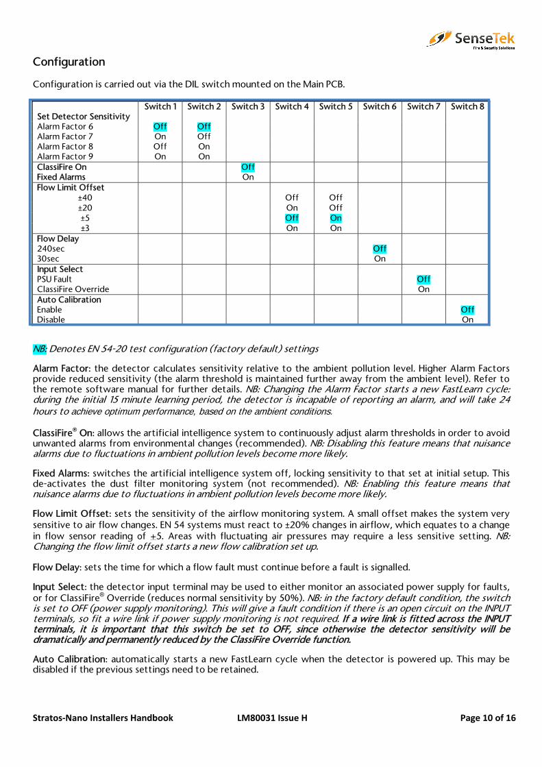
Configuration
Configuration is carried out via the DIL switch mounted on the Main PCB.
Switch 1 Switch 2 Switch 3 Switch 4 Switch 5 Switch 6 Switch 7 Switch 8Set Detector Sensitivity Alarm Factor 6 Off Off Alarm Factor 7 On Off Alarm Factor 8 Off On Alarm Factor 9 On On ClassiFire On Off Fixed Alarms On Flow Limit Offset
±40 Off Off±20 On Off±5 Off On ±3 On On
Flow Delay 240sec Off 30sec On Input Select PSU Fault Off ClassiFire Override On Auto Calibration Enable Off Disable On
NB: Denotes EN 54-20 test configuration (factory default) settings
Alarm Factor: the detector calculates sensitivity relative to the ambient pollution level. Higher Alarm Factors provide reduced sensitivity (the alarm threshold is maintained further away from the ambient level). Refer to the remote software manual for further details. NB: Changing the Alarm Factor starts a new FastLearn cycle: during the initial 15 minute learning period, the detector is incapable of reporting an alarm, and will take 24 hours to achieve optimum performance, based on the ambient conditions.
ClassiFire® On: allows the artificial intelligence system to continuously adjust alarm thresholds in order to avoid unwanted alarms from environmental changes (recommended). NB: Disabling this feature means that nuisance alarms due to fluctuations in ambient pollution levels become more likely.
Fixed Alarms: switches the artificial intelligence system off, locking sensitivity to that set at initial setup. This de-activates the dust filter monitoring system (not recommended). NB: Enabling this feature means that nuisance alarms due to fluctuations in ambient pollution levels become more likely.
Flow Limit Offset: sets the sensitivity of the airflow monitoring system. A small offset makes the system very sensitive to air flow changes. EN 54 systems must react to ±20% changes in airflow, which equates to a change in flow sensor reading of +5. Areas with fluctuating air pressures may require a less sensitive setting. NB: Changing the flow limit offset starts a new flow calibration set up.
Flow Delay: sets the time for which a flow fault must continue before a fault is signalled.
Input Select: the detector input terminal may be used to either monitor an associated power supply for faults, or for ClassiFire® Override (reduces normal sensitivity by 50%). NB: in the factory default condition, the switch is set to OFF (power supply monitoring). This will give a fault condition if there is an open circuit on the INPUT terminals, so fit a wire link if power supply monitoring is not required. If a wire link is fitted across the INPUT terminals, it is important that this switch be set to OFF, since otherwise the detector sensitivity will be dramatically and permanently reduced by the ClassiFire Override function.
Auto Calibration: automatically starts a new FastLearn cycle when the detector is powered up. This may be disabled if the previous settings need to be retained.

Stratos‐Nano Installers Handbook LM80031 Issue H Page 11 of 16
Commissioning
Local standards and specification requirements must be adhered to. A typical commissioning procedure might entail the following steps:
Check installation against design documentation
Set detector configuration DIL switches as required
Power up detector and wait for 15 minute FastLearn cycle to finish (steady OK LED when complete)
Disconnect detector from fire panel if required
Check/test connections to main Fire Detection and Alarm System
For EN54-20 compliance, thetransport time of the last
sampling hole shall be checkedfollowing all installation and proven to be less than or equal to that
determined by PipeCADs
c
Reconnect detector to fire panel if required
Complete test records, settings and results for reference by maintenance
engineers
Stratos‐Nano Installers Handbook LM80031 Issue H Page 12 of 16
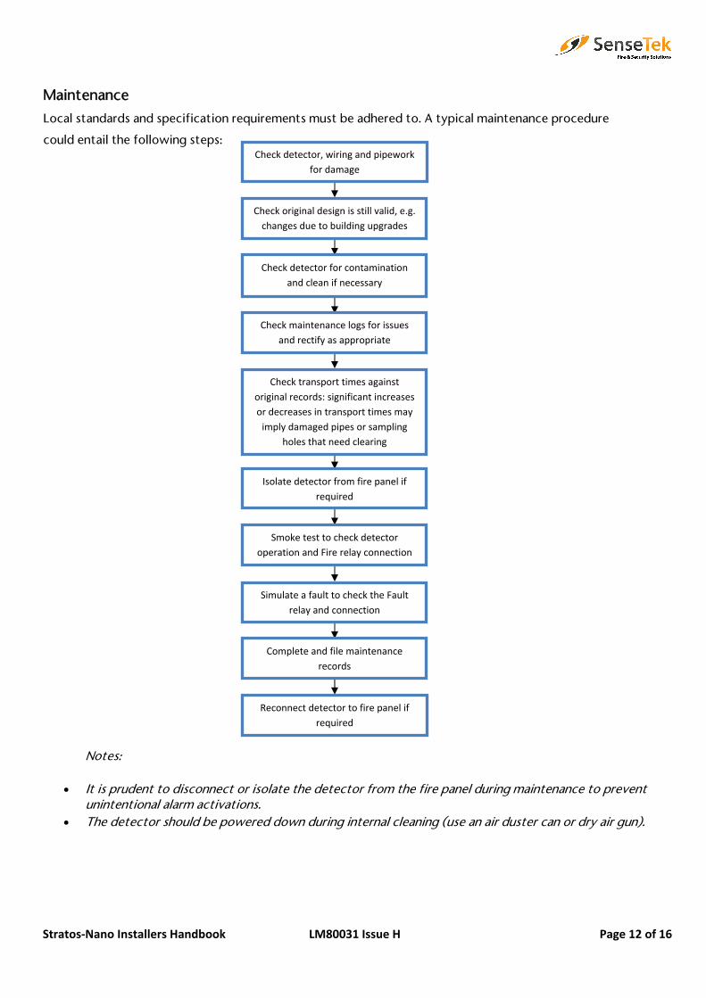
Maintenance
Local standards and specification requirements must be adhered to. A typical maintenance procedure
could entail the following steps:
Notes:
• It is prudent to disconnect or isolate the detector from the fire panel during maintenance to prevent unintentional alarm activations.
• The detector should be powered down during internal cleaning (use an air duster can or dry air gun).
Check detector, wiring and pipework for damage
Check original design is still valid, e.g. changes due to building upgrades
Check detector for contamination and clean if necessary
Check maintenance logs for issues and rectify as appropriate
Check transport times against original records: significant increases or decreases in transport times may imply damaged pipes or sampling
holes that need clearing
Smoke test to check detector operation and Fire relay connection
Simulate a fault to check the Fault relay and connection
Complete and file maintenance records
Isolate detector from fire panel if required
Reconnect detector to fire panel if required

Stratos‐Nano Installers Handbook LM80031 Issue H Page 13 of 16
Troubleshooting
Nuisance alarms:
• This normally indicates that the detector is set at an Alarm Factor inappropriate to the installedenvironment.Increase the Alarm Factor to reduce sensitivity.
• The sensor chamber may be contaminated.Return the sensor chamber for factory cleaning and recalibration.
Detector will not pass smoke a test:
• Detector may be in a FastLearn cycle.Check green OK LED is not flashing.
• The detector FastLearn cycle may have been carried out during or immediately after smoke tests.Reinitiate FastLearn with the detector in a clean environment.
• The Alarm Factor is too high.Change the Alarm Factor to a lower, more sensitive, setting.
Nuisance flow faults:
• Flow monitoring is too sensitive for the environment.Increase the flow limit offset.
• Airflow may be subject to temporary changes (spikes).Increase flow delay.
Long transport times:
• Sampling pipe may be too long or have too many sampling holes/capillaries or incorrect hole sizes.Check design with pipe modelling software.
• Sampling pipes, sampling holes and/or the exhaust pipe may be partially blocked by dust or debris.Clean pipe work with dry compressed air and/or clean the sampling holes.
• Fan may be defective.Send detector for repair.
• Fan lead may be disconnectedReconnect lead.

Stratos‐Nano Installers Handbook LM80031 Issue H Page 14 of 16
Optional: Communications Card
A Communications Card may be fitted inside the detector.
Direct connection of a PC to the Communications Card is via a 9-pin RS-232 interface on the Communications Card, using a Null Modem cable configuration, as shown in the diagram below.
A connected PC may access the detector event memory to review previous or current events such as detector sensitivity. The detector internal Chart Recorder may also be accessed for analysis of detector behaviour (see separate Remote Software Manual for further information). The PC cannot be used to configure the detector except to enter time and date settings for the detector event log and chart recording to be viewed in the Remote Software. The detector does not incorporate a real time clock, so the time and date need to be re-entered if the detector is powered down for any reason.
Installation of the Communications Card also provides the detector with RS-485 network communication via the A, B and SCREEN terminals on the detector main board. This can be used for simple remote display indication or integration into a larger site wide management and display system, separate from the local Fire Detection and Alarm system connection. The Communications Card has short circuit bus isolation but does not have an RS485 repeater
Detector address DIP switch• The detector address is set
using a reverse binary code, i.e. switch 1 is the least significant bit and switch 8 is not used.
• Set to address from 001 to 127 in order to identify the detector to the remote control software
RS-232 serial port • Use 9-pin D-type null modem
cable to connect to PC
Board locating post
2 off M3 x 6 fixing screws• Provided with board.

Stratos‐Nano Installers Handbook LM80031 Issue H Page 15 of 16
Technical Data
SELV Rating…………………………………………..EN 60950 Class III
Supply Voltage……………………………………...21.6v – 26.4v DC
Current Consumption……………………………..350mA
Electrical Safety…………………………………….Complies with EN 610190-1
Size (mm)……………………………………………190w x 230h x 110d
Weight ……………………………………………….1.2kg
Operating Temperature Range…………………..0°C to 38°C (UL 268)
-10°C to 60°C (EN 54-20)
Operating Humidity Range………………………..0 to 90% Relative Humidity, Non-Condensing
EN61010-1 Pollution Degree 1
EN61010-1 Installation Category II
IP Rating……………………………………………...IP50
Sensitivity Range…………………………………...0.4% to 25% obscuration/metre
Detection Principle…………………………………Laser Light Forward Scattering Mass Detection
Maximum Number of Sampling Holes…………..Class A: 2
Class B: 4
Class C: 10
Maximum Sampling Pipe Length………………….50m
Sampling Pipe Inlets………………………………..2 off ¾”pipe inlets (sampling pipe and exhaust)
Alarm / Fault Relays………………………………..Pre-Alarm / Fire / Fault
Relay Contact Rating (Changeover)……………..1A @24V DC resistive load
Programming………………………………………...Internal DIL Switches
PC Interrogation…………………………………….Via optional Communications Card
APIC Compatible……………………………………Yes
Notes: • Some devices such as sounders and beacons have high inrush currents on activation, which can damage
relay contacts. It is good practice to consider fitting a suitable current limiting resistor in series with the load to avoid this potential problem.
e
including pipes, endcaps and sampling holes, enter the detector type in the òTypeó drop-down list in òOptionsó select òCalculation options
involve smoke tests to verify that the system performs as expected and enters Fire 1 alarm within the time determined by PipeCAD from the farthest hole

Stratos‐Nano Installers Handbook LM80031 Issue H Page 16 of 16
EN54-20 Compliance The installation must be designed using PipeCAD software, which is provided free on the CD shipped with each detector. After designing the installation including pipes, endcaps and sampling holes, enter the detector type. To select the detector type, select Options, select Calculation options, and then select the detector from the Type drop-down list.
Select “Options” “Calculate” or click on the calculator icon. The software will prompt you to choose from “Use set hole sizes” “Best flow balance” and “Max. permissible transit time”. Select the appropriate option and click “OK”. The results for each pipe (“View” “Results”) show calculations for each sampling hole on the pipe with the nearest to the detector at the top of the screen, and the endcap hole at the bottom.
The classification of each sampling device configuration and associated sensitivity settings are determined by the column headed “Hole sensitivity % obs/m” which shows the predicted sensitivity for each hole. For the installation to comply with EN54-20 depending on the class of installation, each sampling hole must be no less sensitive than the following:
Class A: 0.80% obs/m Class B: 1.66% obs/m Class C: 5.85% obs/m
The calculation can be further refined by leaving a working detector in the protected area for at least 24hrs at the intended alarm factor for the installation (this could be done before or after installation). The detector sensitivity can be read from the “Sensitivity” figure on the histogram screen of the Remote software supplied with each detector. Click "Options" and then click "Calculation options" to open the "Hole calculation options" dialog box. Enter the sensitivity value obtained from the practical test, and then click OK. The new calculated value will use the the real sensitivity from the practical test.
The PipeCAD software will determine the classification of any used configuration. Commissioning and periodic system tests must involve smoke tests to verify that the system performs as expected and enters Fire 1 alarm within the time determined by PipeCAD from the farthest hole. The detector sensitivity must also be inspected to ensure it has not radically fallen from the installed figure. If it has changed for any reason, the new figure must be re-entered into PipeCAD and the recalculated hole sensitivities must be confirmed to be within the class limits shown above.