Embed Size (px)
Citation preview

Routers

THE OSI REFERENCE MODEL
OVERVIEW
• THE NEED FOR STANDARDS• OSI - ORGANISATION FOR STANDARDISATION• THE OSI REFERENCE MODEL• A LAYERED NETWORK MODEL• THE SEVEN OSI REFERENCE MODEL LAYERS• SUMMARY
THE NEED FOR STANDARDS
• Over the past couple of decades many of the networks that were built used different hardware and software implementations, as a result they were incompatible and it became difficult for networks using different specifications to communicate with each other.
• To address the problem of networks being incompatible and unable to communicate with each other, the International Organisation for Standardisation (ISO) researched various network schemes.
• The ISO recognised there was a need to create a NETWORK MODEL that
would help vendors create interoperable network implementations.
ISO - ORGANISATION FOR STANDARDISATION
• The International Organisation for Standardisation (ISO) is an International standards organisation responsible for a wide range of standards, including many that are relevant to networking.
• In 1984 in order to aid network interconnection without necessarily requiring complete redesign, the Open Systems Interconnection (OSI) reference model was approved as an international standard for communications architecture.
THE OSI REFERENCE MODEL
• The model was developed by the International Organisation for Standardisation (ISO) in 1984. It is now considered the primary Architectural model for inter-computer communications.
• The Open Systems Interconnection (OSI) reference model is a descriptive network scheme. It ensures greater compatibility and interoperability between various types of network technologies.
• The OSI model describes how information or data makes its way from application programmes (such as spreadsheets) through a network medium (such as wire) to another application programme located on another network.
• The OSI reference model divides the problem of moving information between computers over a network medium into SEVEN smaller and more manageable problems .
• This separation into smaller more manageable functions is known as layering.
A LAYERED NETWORK MODEL
• The OSI Reference Model is composed of seven layers, each specifying particular network functions.
• The process of breaking up the functions or tasks of networking into layers reduces complexity.
• Each layer provides a service to the layer above it in the protocol specification.
• Each layer communicates with the same layer’s software or hardware on other computers.
• The lower 4 layers (transport, network, data link and physical —Layers 4, 3, 2, and 1) are concerned with the flow of data from end to end through the network.
• The upper four layers of the OSI model (application, presentation and session—Layers 7, 6 and 5) are orientated more toward services to the applications.
• Data is Encapsulated with the necessary protocol information as it moves down the layers before network transit.

THE SEVEN OSI REFERENCE MODEL
LAYERS
LAYER 7: APPLICATION
• The application layer is the OSI layer that is closest to the user.
• It provides network services to the user’s applications.
• It differs from the other layers in that it does not provide services to any other OSI layer, but rather, only to applications outside the OSI model.
• Examples of such applications are spreadsheet programs, word processing programs, and bank terminal programs.
• The application layer establishes the availability of intended communication partners, synchronizes and establishes agreement on procedures for error recovery and control of data integrity.
LAYER 6: PRESENTATION
• The presentation layer ensures that the information that the application layer of one system sends out is readable by the application layer of another system.
• If necessary, the presentation layer translates between multiple data formats by using a common format.
• Provides encryption and compression of data.• Examples :- JPEG, MPEG, ASCII, EBCDIC, HTML.
LAYER 5: SESSION
• The session layer defines how to start, control and end conversations (called sessions) between applications.
• This layer establishes, manages and terminates communication sessions between applications.
• This includes the control and management of multiple bi-directional messages using dialogue control.
• It also synchronizes dialogue between two hosts' presentation layers and manages their data exchange.
• The session layer offers provisions for efficient data transfer.
• Examples :- SQL, ASP(AppleTalk Session Protocol).
LAYER 4: TRANSPORT
• The transport layer regulates information flow to ensure end-to-end connectivity between host applications reliably and accurately.
• The transport layer segments data from the sending host's system and reassembles the data into a data stream on the receiving host's system.
• The transport-layer provides end-to-end transport services. It constitutes a logical connection between the originating point and the destination point.
• It ensures data integrity through the use of checksum calculations on the data and provide flow control mechanisms. Overflows in the buffer of receiving station can cause loss of data.
• Data reliability ensures that data is received is the same order in which it was sent.
cont.

LAYER 4: TRANSPORT• The boundary between the transport layer and the session layer can
be thought of as the boundary between application protocols and data-flow protocols. Whereas the application, presentation, and session layers are concerned with application issues, the lower four layers are concerned with data transport issues.
• Layer 4 protocols include TCP (Transmission Control Protocol) and UDP (User Datagram Protocol).

LAYER 3: NETWORK
• Defines end-to-end delivery of packets. • Defines logical addressing so that any endpoint can be identified. • Defines how routing works and how routes are learned so that the packets
can be delivered. • The network layer also defines how to fragment a packet into smaller
packets to accommodate different media.• Routers operate at Layer 3.• Examples :- IP, IPX, AppleTalk.
LAYER 2: DATA LINK
• The data link layer provides access to the networking media and physical transmission across the media and this enables the data to locate its intended destination on a network.
• The data link layer provides reliable transit of data across a physical link by using the Media Access Control (MAC) addresses.
• The data link layer uses the MAC address to define a hardware or data link address in order for multiple stations to share the same medium and still uniquely identify each other.
• Concerned with network topology, network access, error notification, ordered delivery of frames, and flow control.
• Examples :- Ethernet, Frame Relay, FDDI.
LAYER 1: PHYSICAL
• The physical layer deals with the physical characteristics of the transmission medium.
• It defines the electrical, mechanical, procedural, and functional specifications for activating, maintaining, and deactivating the physical link between end systems.
• Such characteristics as voltage levels, timing of voltage changes, physical data rates, maximum transmission distances, physical connectors, and other similar attributes are defined by physical layer specifications.
• Examples :- EIA/TIA-232, RJ45.

Connection-Oriented Protocol
• For reliable transport services.• Acknowledgements exchanged
between the sender and the receiver.• Slow but reliable.• Flow control & congestion avoidance.• Example: TCP
Connection-less Oriented Protocol
• Unreliable data transfer.• No acknowledgements exchanged.• Unreliable but fast.• Example: UDP
SUMMARY• There was no standard for networks in the early days and as a result it was
difficult for networks to communicate with each other.
• The International Organisation for Standardisation (ISO) recognised this. and researched various network schemes, and in 1984 introduced the Open Systems Interconnection (OSI) reference model.
• The OSI reference model has standards which ensure vendors greater compatibility and interoperability between various types of network technologies.
• The OSI reference model organizes network functions into seven numbered layers.
• Each layer provides a service to the layer above it in the protocol specification and communicates with the same layer’s software or hardware on other computers.
• Layers 1-4 are concerned with the flow of data from end to end through the network and Layers 5-7 are concerned with services to the applications.
NETWORK DEVICES

HUBS
• Work on physical layer.• No addressing involved.• Used for LAN extension.• Data received on 1 port is transmitted
(broadcast) on all the ports.• Suitable for smaller LANs
SWITCHES
• Work on Data Link layer.• They are intelligent devices.• Used for LAN extension.• Maintain a table of MAC addresses of
the connected devices.• Frames received on 1 port are transmitted
out the appropriate port to which the destination device is connected.
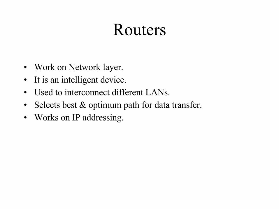
Routers
• Work on Network layer.• It is an intelligent device.• Used to interconnect different LANs.• Selects best & optimum path for data transfer.• Works on IP addressing.
ROUTER

What is a Router?
A device which forwards packetsbetween networks. The forwarding decision is basedon network layer information androuting tables, often constructedby routing protocols.
CISCO SYSTEMS
• CISCO Systems provides a variety of internetworking hardware and software including– Routers– Switches and Concentrators– IP telephony– Firewall– Video– Wireless– Broadband– Network management software
Routing Hardware vs. Software
Routing can be accomplished via hardware or software.
• HARDWARE: For our purposes routing hardware is defined as a device who’s primary purpose is to route internetwork traffic.
• SOFTWARE: Routing functions can be performed by software on any multi-homed network device (Say Windows 2000™ with two network interface cards)
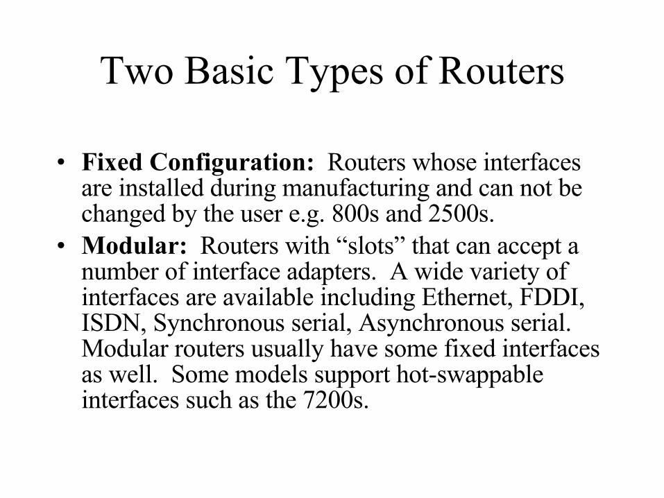
Two Basic Types of Routers
• Fixed Configuration: Routers whose interfaces are installed during manufacturing and can not be changed by the user e.g. 800s and 2500s.
• Modular: Routers with “slots” that can accept a number of interface adapters. A wide variety of interfaces are available including Ethernet, FDDI, ISDN, Synchronous serial, Asynchronous serial. Modular routers usually have some fixed interfaces as well. Some models support hot-swappable interfaces such as the 7200s.
COMPONENTS OF A ROUTER
Hardware/Software
• RAM/DRAM• NVRAM• Flash Memory• ROM• IOS
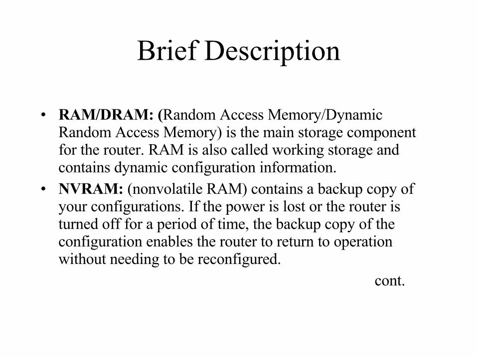
Brief Description
• RAM/DRAM: (Random Access Memory/Dynamic Random Access Memory) is the main storage component for the router. RAM is also called working storage and contains dynamic configuration information.
• NVRAM: (nonvolatile RAM) contains a backup copy of your configurations. If the power is lost or the router is turned off for a period of time, the backup copy of the configuration enables the router to return to operation without needing to be reconfigured.
cont.
• Flash Memory/IOS: It is a special kind of erasable, programmable read-only memory. This memory contains a copy of the Cisco Internetwork Operating System (Cisco IOS) software. Flash memory has a structure that enable it to store multiple copies of the IOS software. Flash memory content is retained when you power down or restart.
• ROM: (Read only memory) contains an initializing bootstrap program and a small monitoring system that can be used for recovery from a catastrophe.
Power-up procedure of a Router
• Check hardware & conduct power-on-self-test (POST).
• Find and load the Cisco IOS software image. The image is the data the router uses for its operating system.
• Find and apply the router configuration information.
ACCESSING A ROUTER
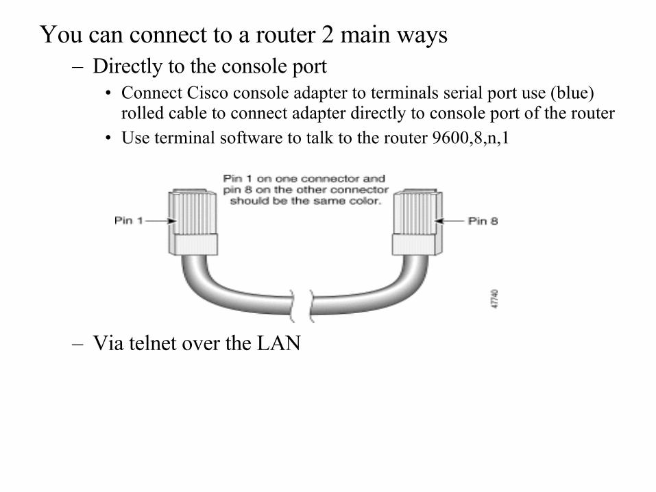
You can connect to a router 2 main ways– Directly to the console port
• Connect Cisco console adapter to terminals serial port use (blue) rolled cable to connect adapter directly to console port of the router
• Use terminal software to talk to the router 9600,8,n,1
– Via telnet over the LAN

DIFFERENT INTERFACES OF A ROUTER

• Ethernet port– RJ-45 or AUI– 10Mbps/100Mbps– For LAN connectivity
• Serial port– DB-60 interface– For WAN connectivity– Synchronous/Asynchronous
• Auxiliary port– RJ-45– Used for Remote Dial-in

MODES OF A ROUTERCOMMANDS USED IN DIFFERENT
MODES

• User Mode• Privileged Mode (enable)
– Global Configuration– Interface Configuration
• Router maintenance– Saving your configuration– rommon
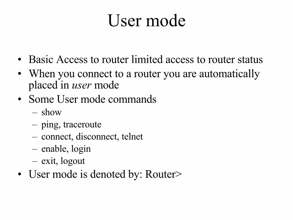
User mode
• Basic Access to router limited access to router status• When you connect to a router you are automatically
placed in user mode • Some User mode commands
– show– ping, traceroute– connect, disconnect, telnet– enable, login– exit, logout
• User mode is denoted by: Router>
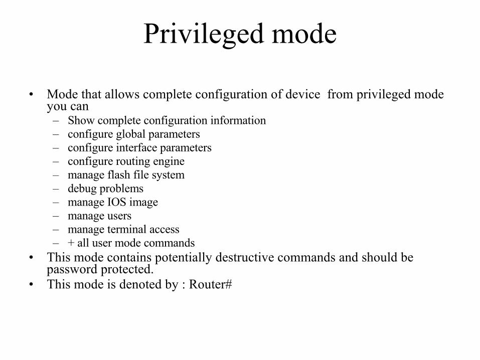
Privileged mode
• Mode that allows complete configuration of device from privileged mode you can– Show complete configuration information– configure global parameters– configure interface parameters– configure routing engine– manage flash file system– debug problems– manage IOS image– manage users– manage terminal access– + all user mode commands
• This mode contains potentially destructive commands and should be password protected.
• This mode is denoted by : Router#
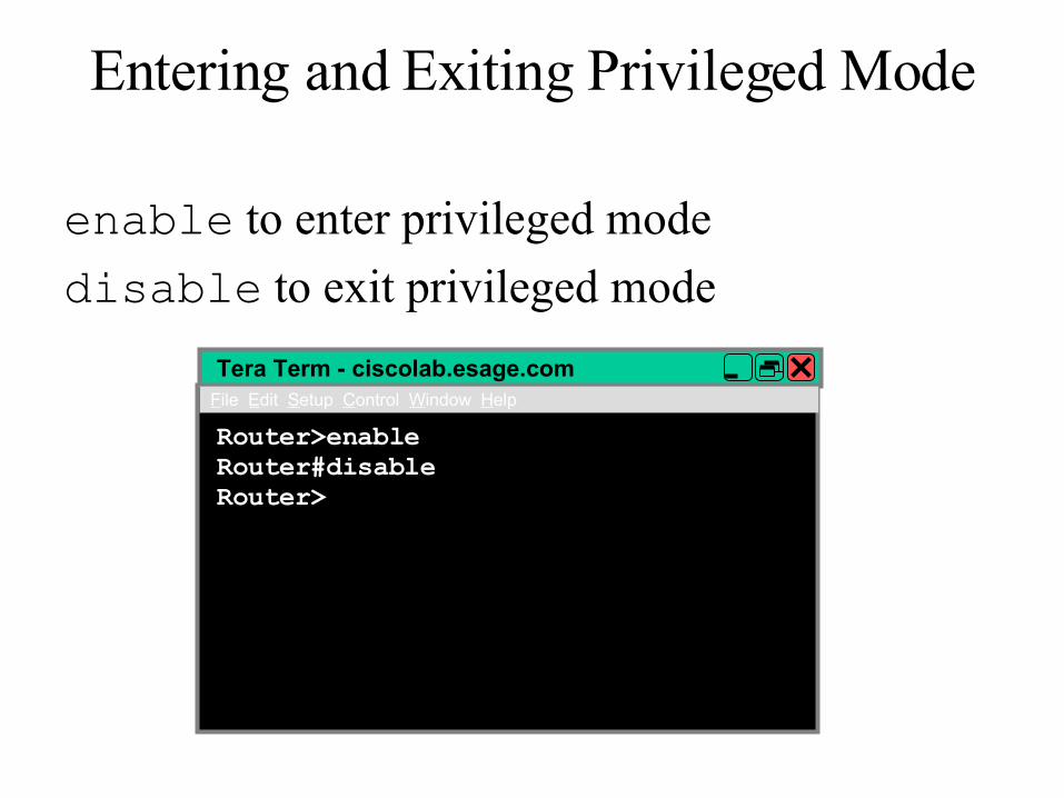
Entering and Exiting Privileged Mode
enable to enter privileged mode
disable to exit privileged mode
Tera Term - ciscolab.esage.comFile Edit Setup Control Window Help
Router>enableRouter#disableRouter>
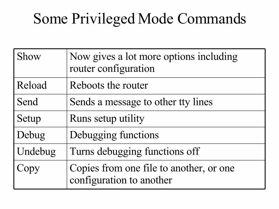
Some Privileged Mode Commands
Copies from one file to another, or one configuration to another
Copy
Turns debugging functions offUndebug
Debugging functionsDebug
Runs setup utilitySetup
Sends a message to other tty linesSend
Reboots the routerReload
Now gives a lot more options including router configuration
Show

Global configuration mode
• Global configuration commands apply to features that affect the system as a whole.
• Router# configure terminal• Router(config)#
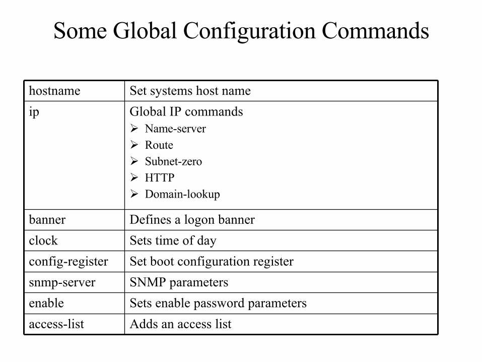
Some Global Configuration Commands
Adds an access listaccess-list
Sets enable password parametersenable
SNMP parameterssnmp-server
Set boot configuration registerconfig-register
Sets time of dayclock
Defines a logon bannerbanner
Global IP commands Name-server Route Subnet-zero HTTP Domain-lookup
ip
Set systems host namehostname
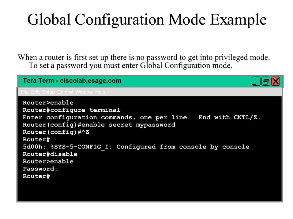
Global Configuration Mode Example
When a router is first set up there is no password to get into privileged mode. To set a password you must enter Global Configuration mode.
Tera Term - ciscolab.esage.com
File Edit Setup Control Window Help
Router>enableRouter#configure terminalEnter configuration commands, one per line. End with CNTL/Z.Router(config)#enable secret mypasswordRouter(config)#^ZRouter#5d00h: %SYS-5-CONFIG_I: Configured from console by consoleRouter#disableRouter>enablePassword:Router#

Interface configuration mode
• The commands entered in this mode effect to a particular interface.
• Router# configure terminal• Router(config)# interface ethernet 0• Router(config-if)#
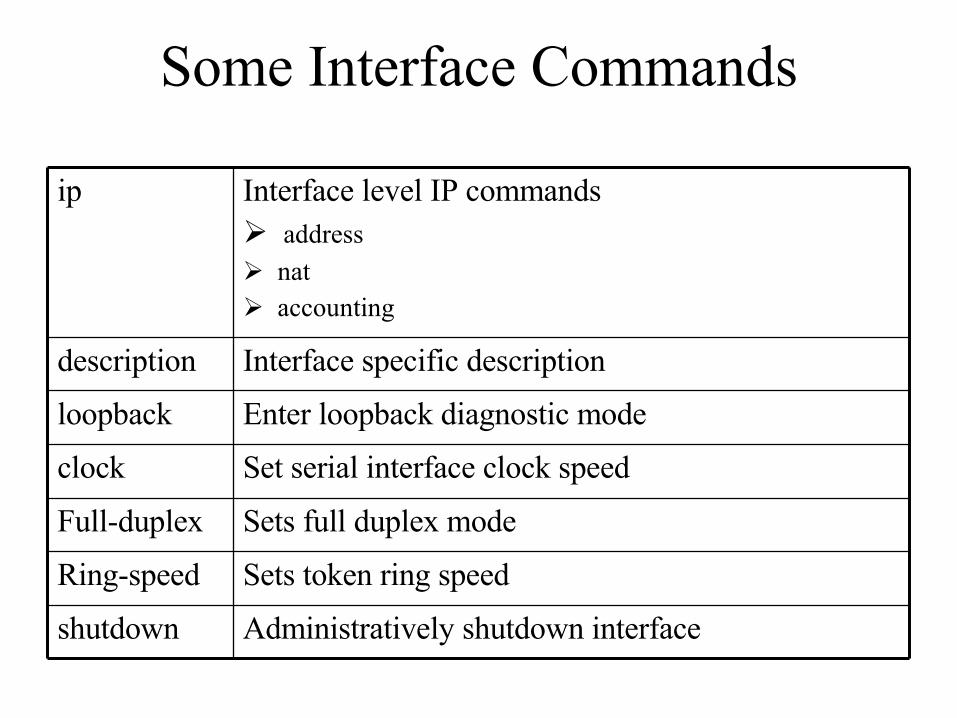
Some Interface Commands
Sets token ring speedRing-speed
Set serial interface clock speedclock
Sets full duplex modeFull-duplex
Administratively shutdown interfaceshutdown
Enter loopback diagnostic modeloopback
Interface specific descriptiondescription
Interface level IP commands address
nat accounting
ip
Interface Configuration ExampleTera Term - ciscolab.esage.com
File Edit Setup Control Window Help
tr1(config)#interface ethernet 0tr1(config-if)#ip address 10.0.10.1 255.255.255.0tr1(config-if)#no shutdown
5d01h: %LINK-5-CHANGED: Interface ethernet0, changed state to initializing5d01h: %LINK-3-UPDOWN: Interface ethernet0, changed state to up5d01h: %LINEPROTO-5-UPDOWN: Line protocol on Interface ethernet0, changed state to uptr1(config-if)#^Z5d01h: %SYS-5-CONFIG_I: Configured from console by consoletr1#ping 10.0.10.254Type escape sequence to abort.Sending 5, 100-byte ICMP Echos to 10.0.10.254, timeout is 2 seconds:!!!!!Success rate is 100 percent (5/5), round-trip min/avg/max = 4/9/32 mstr1#
System Maintenance
• Saving your configuration• Working with file system• ROM Monitor Mode• Mini-IOS (RXBOOT or bootloader)

Saving Your Configuration
• IOS uses NVRAM to save the router’s configuration. On most Cisco devices setting are not automatically saved to NVRAM
• To save you configuration use:copy running-config startup-config
Abbreviate to copy run start
Or write memory
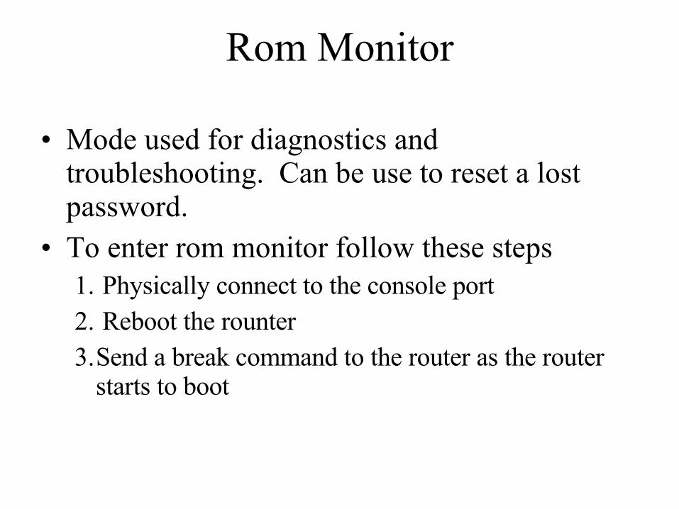
Rom Monitor
• Mode used for diagnostics and troubleshooting. Can be use to reset a lost password.
• To enter rom monitor follow these steps1. Physically connect to the console port2. Reboot the rounter3.Send a break command to the router as the router
starts to boot
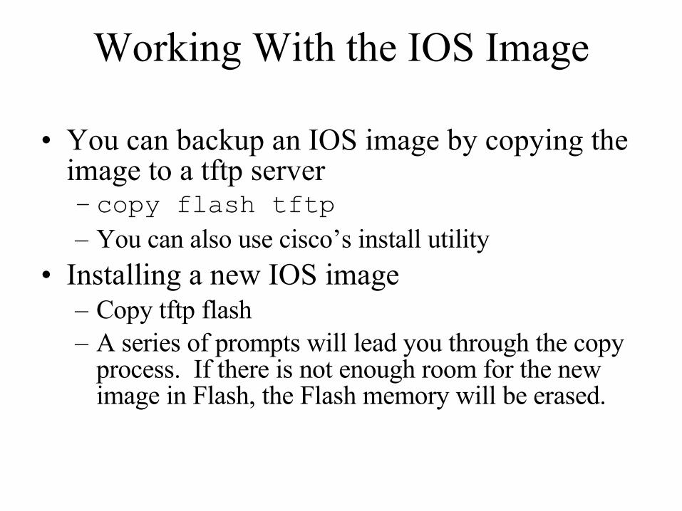
Working With the IOS Image
• You can backup an IOS image by copying the image to a tftp server– copy flash tftp– You can also use cisco’s install utility
• Installing a new IOS image– Copy tftp flash– A series of prompts will lead you through the copy
process. If there is not enough room for the new image in Flash, the Flash memory will be erased.

ROUTING
What is a ROUTE?
• A ROUTE is a path from the sending device to the receiving device.
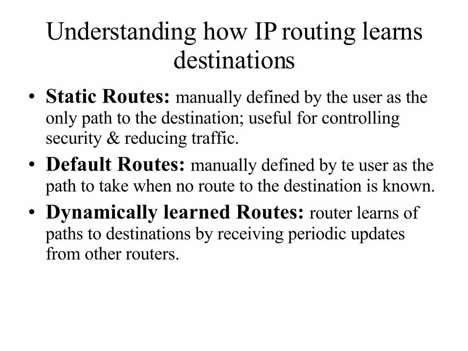
Understanding how IP routing learns destinations
• Static Routes: manually defined by the user as the only path to the destination; useful for controlling security & reducing traffic.
• Default Routes: manually defined by te user as the path to take when no route to the destination is known.
• Dynamically learned Routes: router learns of paths to destinations by receiving periodic updates from other routers.
Static Routing
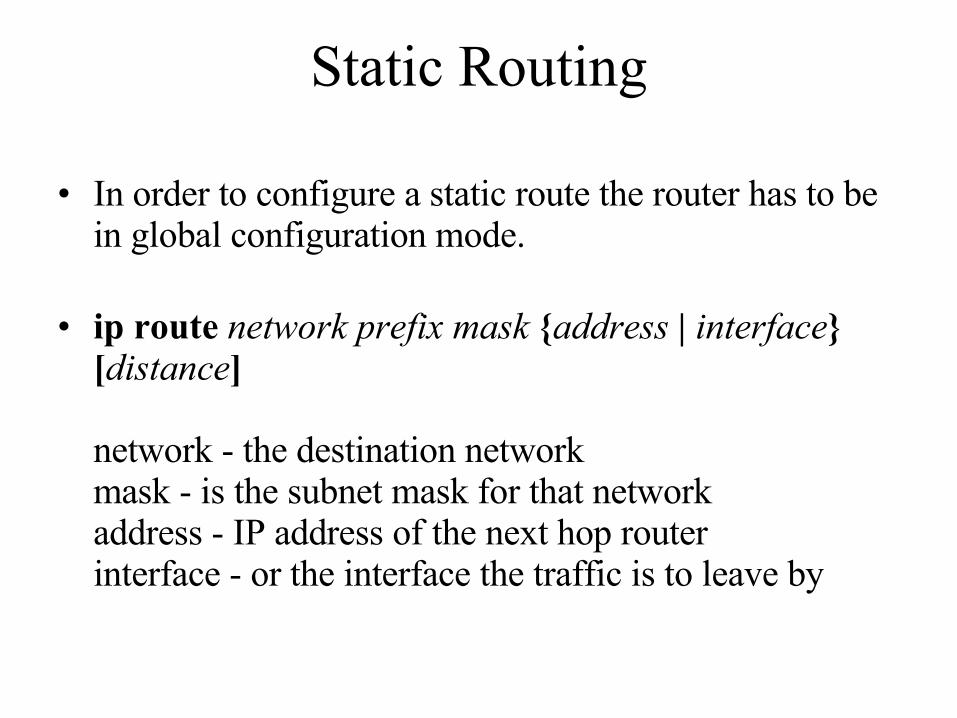
• In order to configure a static route the router has to be in global configuration mode.
• ip route network prefix mask {address | interface} [distance]
network - the destination networkmask - is the subnet mask for that networkaddress - IP address of the next hop routerinterface - or the interface the traffic is to leave by
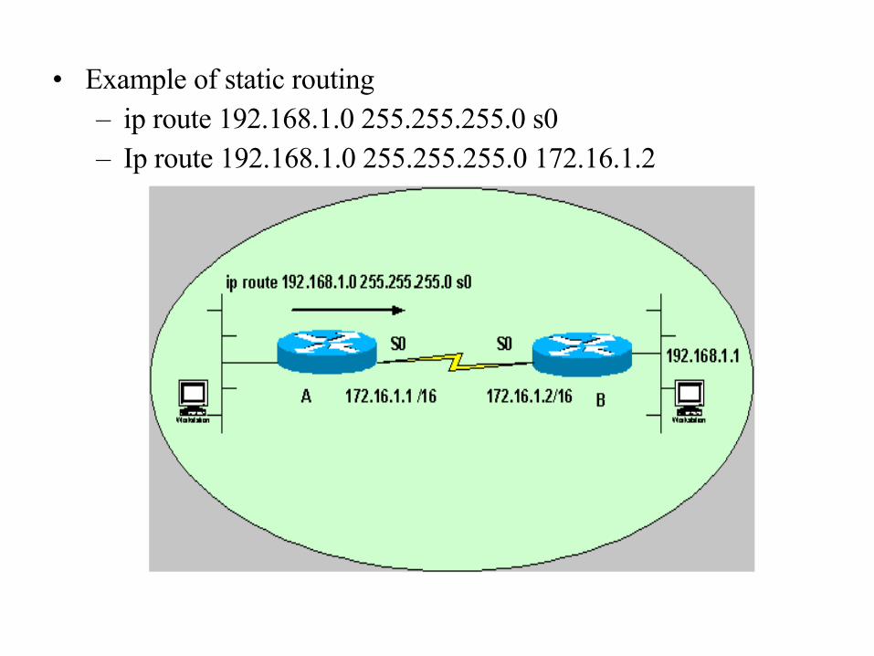
• Example of static routing– ip route 192.168.1.0 255.255.255.0 s0– Ip route 192.168.1.0 255.255.255.0 172.16.1.2
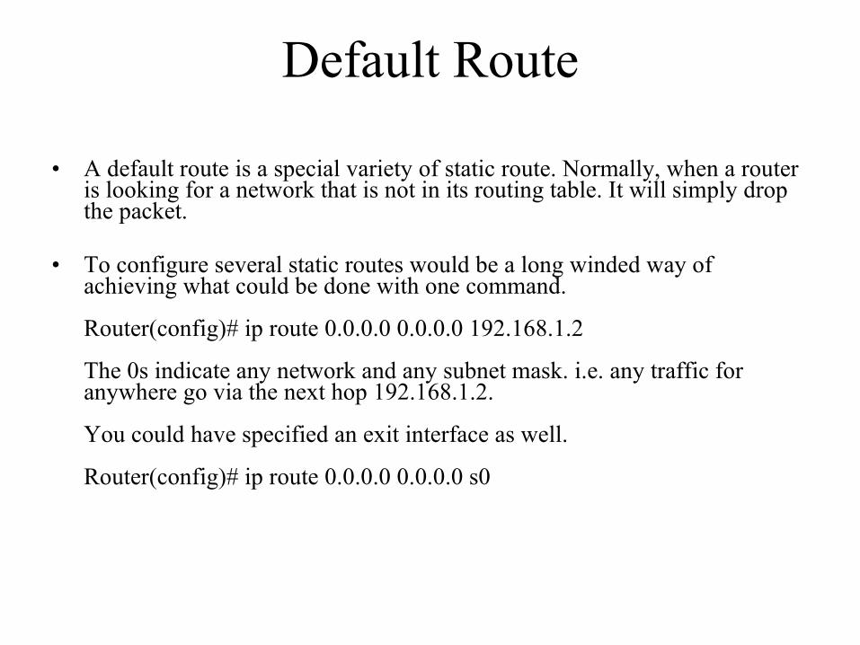
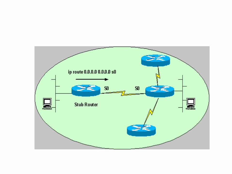
Default Route
• A default route is a special variety of static route. Normally, when a router is looking for a network that is not in its routing table. It will simply drop the packet.
• To configure several static routes would be a long winded way of achieving what could be done with one command.
Router(config)# ip route 0.0.0.0 0.0.0.0 192.168.1.2
The 0s indicate any network and any subnet mask. i.e. any traffic for anywhere go via the next hop 192.168.1.2.
You could have specified an exit interface as well.
Router(config)# ip route 0.0.0.0 0.0.0.0 s0

Understanding IP addressing
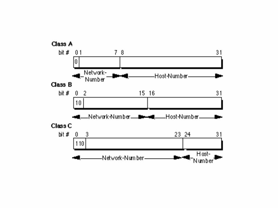
Every computer that communicates over the Internet is assigned an IP address that uniquely identifies the device and distinguishes it from other computers on the Internet. An IP address consists of 32 bits, often shown as 4 octets of numbers from 0-255 represented in decimal form.

• An IP address consists of two parts:– one identifying the network number.– one identifying the node, or host.
• The Class of the address determines which part belongs to the network address and which part belongs to the node address. All nodes on a given network share the same network prefix but must have a unique host number.
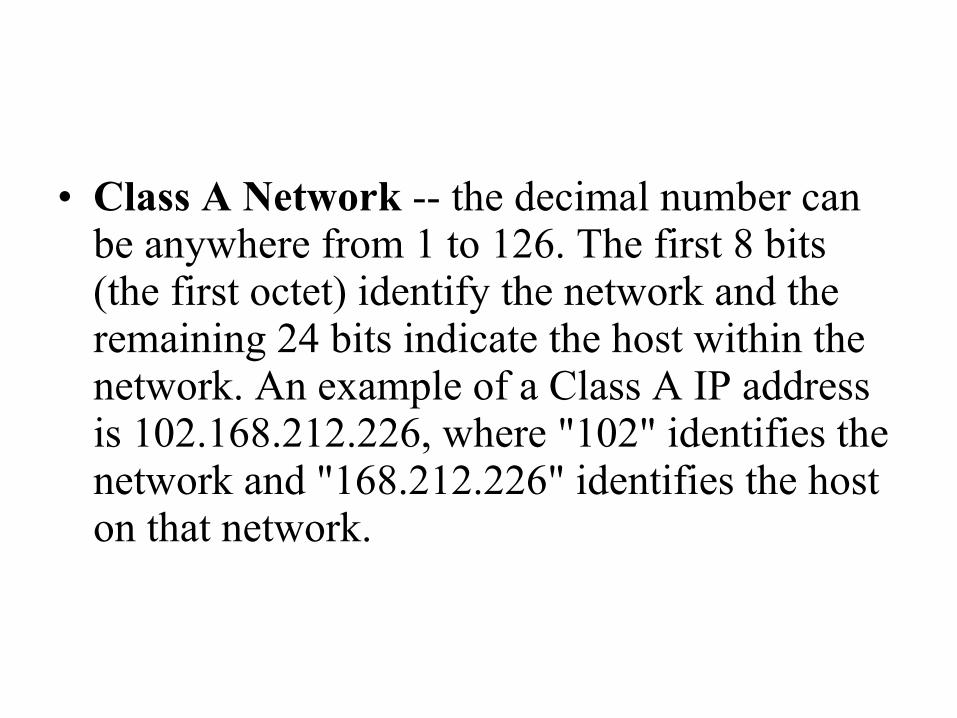
• Class A Network -- the decimal number can be anywhere from 1 to 126. The first 8 bits (the first octet) identify the network and the remaining 24 bits indicate the host within the network. An example of a Class A IP address is 102.168.212.226, where "102" identifies the network and "168.212.226" identifies the host on that network.
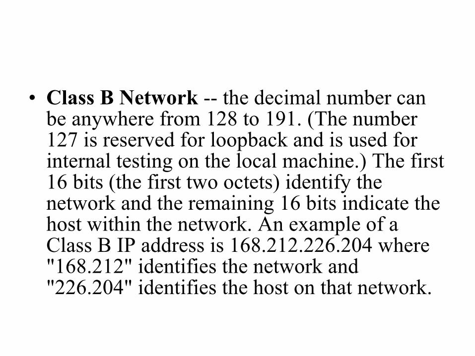
• Class B Network -- the decimal number can be anywhere from 128 to 191. (The number 127 is reserved for loopback and is used for internal testing on the local machine.) The first 16 bits (the first two octets) identify the network and the remaining 16 bits indicate the host within the network. An example of a Class B IP address is 168.212.226.204 where "168.212" identifies the network and "226.204" identifies the host on that network.
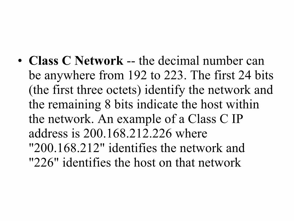
• Class C Network -- the decimal number can be anywhere from 192 to 223. The first 24 bits (the first three octets) identify the network and the remaining 8 bits indicate the host within the network. An example of a Class C IP address is 200.168.212.226 where "200.168.212" identifies the network and "226" identifies the host on that network

Wide Area Networking
WAN Definition
Wide Area Network. A computer network which spans great distances. Usually connects many LANs together.

WAN Technologies
• PSTN Network.• Radios.• VSATs.• Frame-Relay.
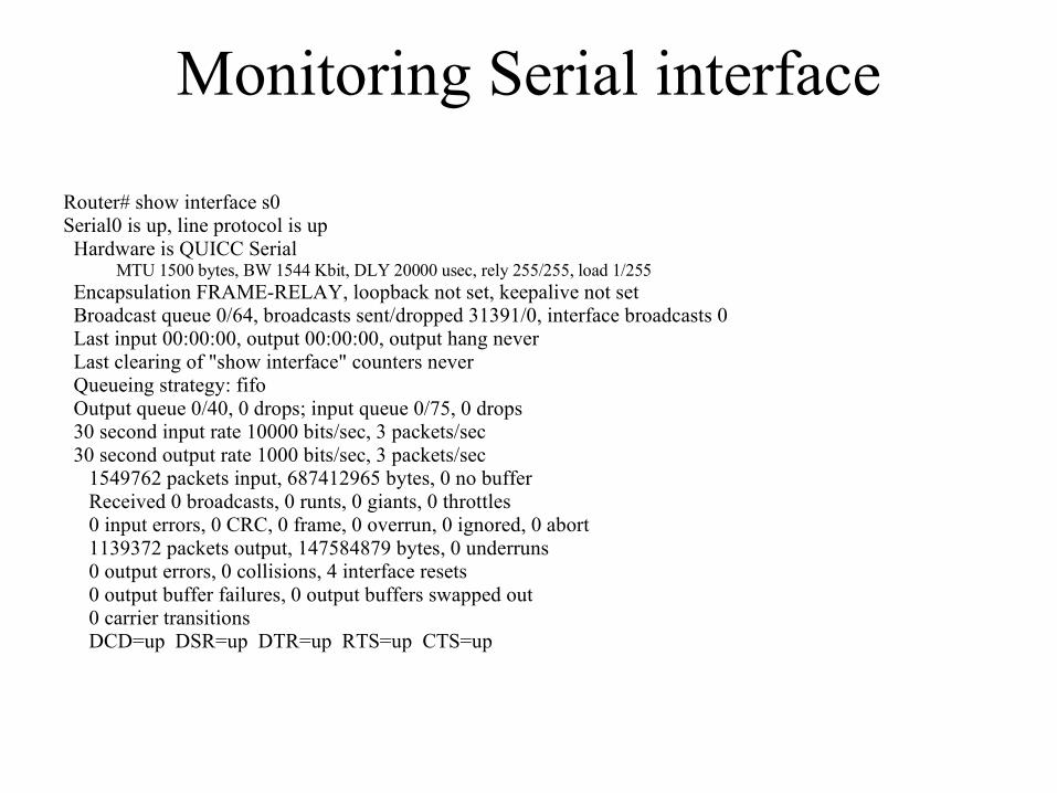
Monitoring Serial interface
Router# show interface s0Serial0 is up, line protocol is up Hardware is QUICC Serial
MTU 1500 bytes, BW 1544 Kbit, DLY 20000 usec, rely 255/255, load 1/255 Encapsulation FRAME-RELAY, loopback not set, keepalive not set Broadcast queue 0/64, broadcasts sent/dropped 31391/0, interface broadcasts 0 Last input 00:00:00, output 00:00:00, output hang never Last clearing of "show interface" counters never Queueing strategy: fifo Output queue 0/40, 0 drops; input queue 0/75, 0 drops 30 second input rate 10000 bits/sec, 3 packets/sec 30 second output rate 1000 bits/sec, 3 packets/sec 1549762 packets input, 687412965 bytes, 0 no buffer Received 0 broadcasts, 0 runts, 0 giants, 0 throttles 0 input errors, 0 CRC, 0 frame, 0 overrun, 0 ignored, 0 abort 1139372 packets output, 147584879 bytes, 0 underruns 0 output errors, 0 collisions, 4 interface resets 0 output buffer failures, 0 output buffers swapped out 0 carrier transitions DCD=up DSR=up DTR=up RTS=up CTS=up
VoIP
• VoIP stands for "Voice over Internet Protocol". A (VoIP) application meets the challenges of combining legacy voice networks and packet networks by allowing both voice and signaling information to be transported over the packet network.
An overview of VoIP
The public telephone network and the equipment that makes it possible are taken for granted in most parts of the world. Availability of a telephone and access to a low-cost, high-quality worldwide network is considered to be essential in modern society (telephones are even expected to work when the power is off). Anything that would jeopardize this is usually treated with suspicion. There is, however, a paradigm shift beginning to occur since more and more communications is in digital form and transported via packet networks such as IP, ATM cells, and Frame Relay frames. Since data traffic is growing much faster than telephone traffic, there has been considerable interest in transporting voice over data networks (as opposed to the more traditional data over voice networks).
Reasons of popularity
• Low-cost, flat rate pricing of the public Internet.
• Convergence of the voice, video, and data communications industries.
• Huge savings on long distance calls