Embed Size (px)
Citation preview

HVAC | Slide 1 of 31 May 2006
Heating, Ventilation and Air- Conditioning (HVAC)
Part 1 (b):
Introduction and overview
Supplementary Training Modules on Good Manufacturing Practice
WHO Technical Report Series, No. 937, 2006. Annex 2
HVAC | Slide 2 of 31 May 2006
HVAC
Objectives
To continue from Part 1(a), now focus on:
Air filtration
The role of HVAC in dust control
HVAC system design and its components (part 2)
Commissioning, qualification and maintenance (part 3)
HVAC | Slide 3 of 31 May 2006
HVAC
Air Filtration
Degree of filtration is important to prevent contamination
Type of filters to be used dependent on the quality of ambient air, return air and air change rates
Manufacturer to determine, select and prove appropriate filters for use considering level of ambient air contamination, national requirements, product specific requirements
4.2.1, 4.2.3
HVAC | Slide 4 of 31 May 2006
HVAC
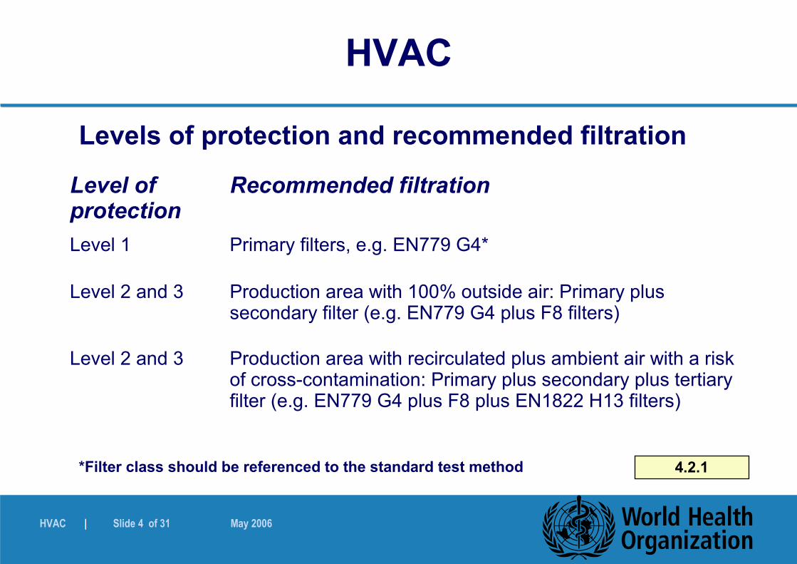
Levels of protection and recommended filtration
*Filter class should be referenced to the standard test method 4.2.1
Level of protection
Recommended filtration
Level 1 Primary filters, e.g. EN779 G4*
Level 2 and 3 Production area with 100% outside air: Primary plus secondary filter (e.g. EN779 G4 plus F8 filters)
Level 2 and 3 Production area with recirculated plus ambient air with a risk of cross-contamination: Primary plus secondary plus tertiary filter (e.g. EN779 G4 plus F8 plus EN1822 H13 filters)

HVAC | Slide 5 of 31 May 2006
HVAC
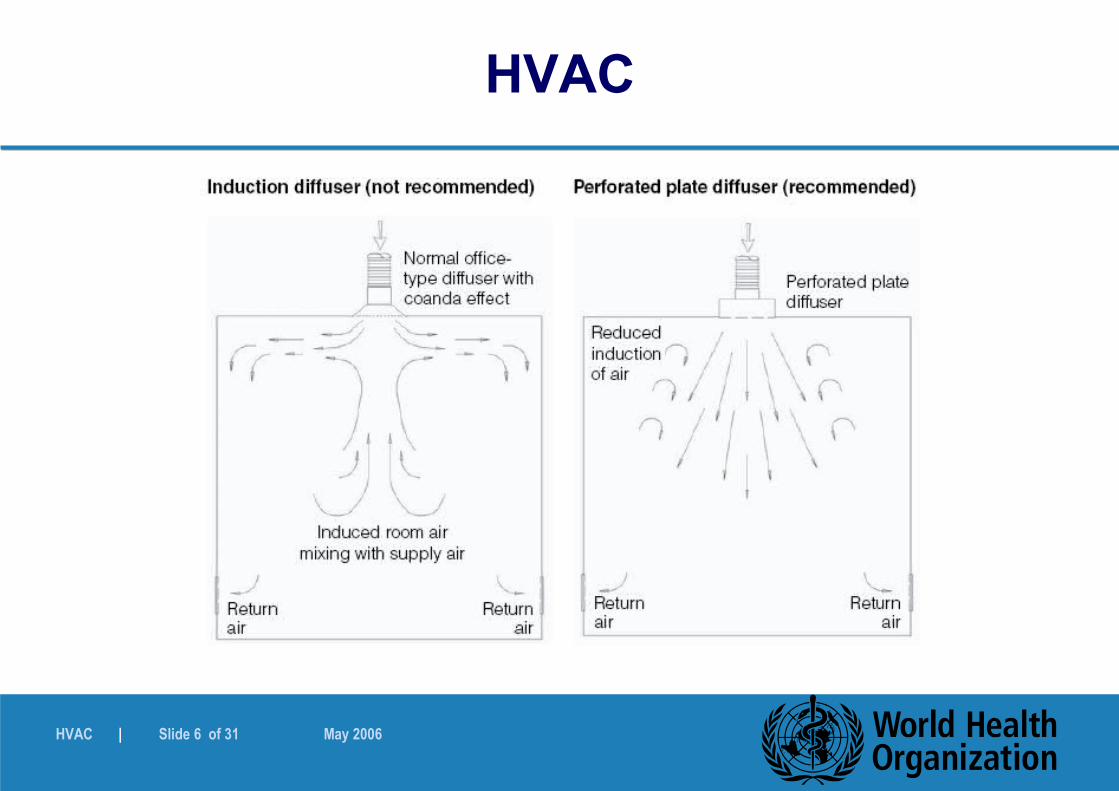
Contamination should be prevented through appropriate:
Materials for components and construction
Design and appropriate access to dampers, filters and other components
Personnel operations
Airflow direction
Air distribution component design and installation and location
Type of diffusers (non-induction type recommended)
Air exhaust (normally from a low level) 4.2.4 – 4.2.10
HVAC | Slide 6 of 31 May 2006
HVAC

HVAC | Slide 7 of 31 May 2006
HVAC
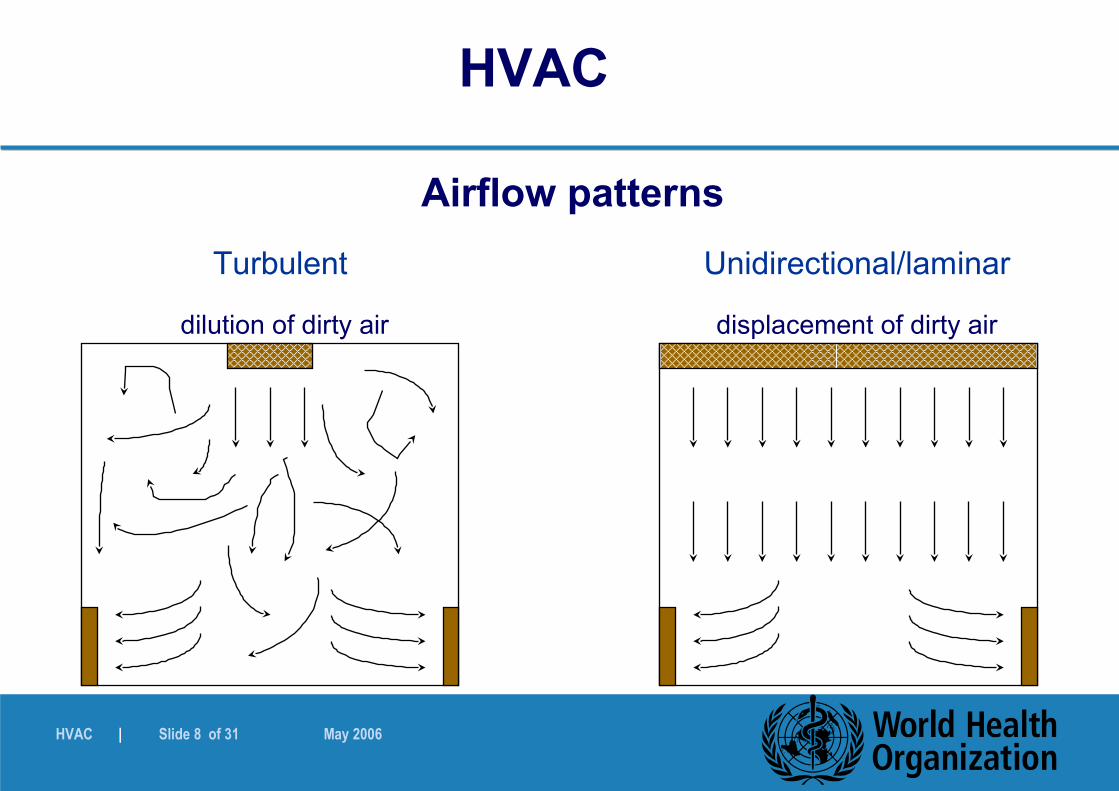
Airflow patterns
Filtered air entering a production room or covering a process can be
� turbulent, or� unidirectional (laminar)
� GMP aspect � economical aspect
Other technologies: barrier technology/isolator technology.
HVAC | Slide 8 of 31 May 2006
Unidirectional/laminar
displacement of dirty air
Turbulent
dilution of dirty air
Airflow patterns
HVAC
HVAC | Slide 9 of 31 May 2006
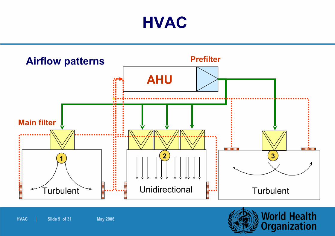
PrefilterAirflow patterns
AHU
Main filter
Unidirectional TurbulentTurbulent
1 2 3
HVAC

HVAC | Slide 10 of 31 May 2006
Workbench (vertical) Cabin/booth Ceiling
Airflow patterns (4)
HVAC
HVAC | Slide 11 of 31 May 2006
HVAC
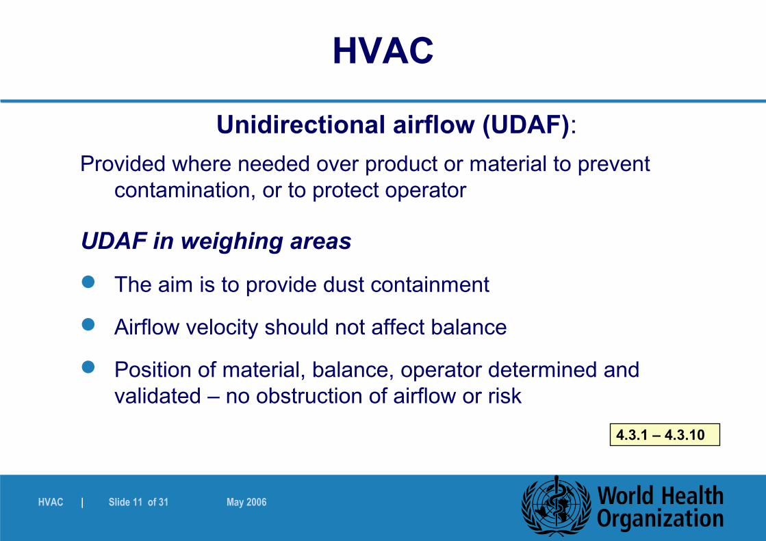
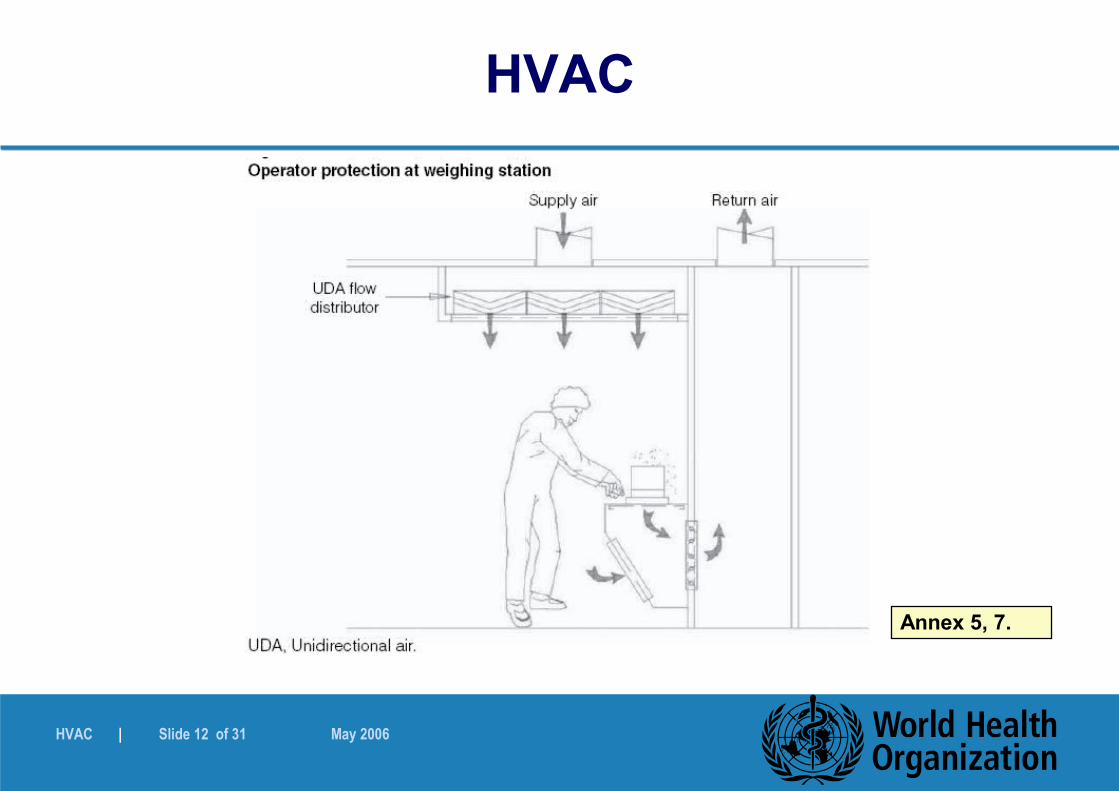
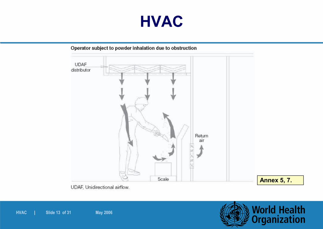
Unidirectional airflow (UDAF):
Provided where needed over product or material to prevent contamination, or to protect operator
UDAF in weighing areas
The aim is to provide dust containment
Airflow velocity should not affect balance
Position of material, balance, operator determined and validated – no obstruction of airflow or risk
4.3.1 – 4.3.10
HVAC | Slide 12 of 31 May 2006
HVAC
Annex 5, 7.
HVAC | Slide 13 of 31 May 2006
HVAC
Annex 5, 7.
HVAC | Slide 14 of 31 May 2006
HVAC
Infiltration
Facilities normally under positive pressure to the outside
Prevent infiltration of unfiltered, contaminated air from outside
Some cases - negative pressure (e.g. penicillin manufacture). Special precautions to be taken
4.4.1 – 4.4.4
HVAC | Slide 15 of 31 May 2006
HVAC
Cross-contamination
General aspects and concepts
Displacement concept
– low pressure differential, high airflow
Pressure differential concept
– high pressure differential, low airflow
Physical barrier concept4.5
HVAC | Slide 16 of 31 May 2006
HVAC
General aspects
Multiproduct OSD manufacturing, prevent movement of dust between areas where different products are processed
Directional air movement and pressure cascade can be helpful – dust containment
Normally, corridor at higher pressure than cubicles, cubicles at higher pressure than atmosphere
4.5.1 – 4.5.3
HVAC | Slide 17 of 31 May 2006
HVAC
Containment concepts
Pressure cascade regime influenced by:– Product and product group, e.g. highly potent products (in
some cases, pressure cascade regime negative to atmosphere)
– Processing methods
Building structure should be considered including airtight ceilings and walls, close fitting doors, sealed light fittings
4.5.4 – 4.5.9
HVAC | Slide 18 of 31 May 2006
HVAC
Displacement concept
Air supplied to the corridor, through the doors (grilles) to the cubicles
Air extracted at the back of the cubicle
Velocity high enough to prevent turbulence in doorway
Requires large air quantities
(Not preferred method) 4.5.10 – 4.5.12
HVAC | Slide 19 of 31 May 2006
HVAC
Pressure differential concept
Concept can include high pressure differential, low airflow, and airlocks in the design
Airlock types include: Cascade, sink and bubble type
Sufficient pressure differential required to ensure containment and prevent flow reversal – but not so high as to create turbulence
Consider effect of other items such as equipment and extraction systems in cubicles
Operating limits and tolerances 4.5.13 – 4.5.18, 4.5.22
HVAC | Slide 20 of 31 May 2006
HVAC
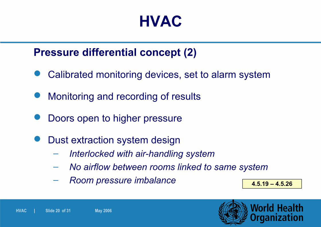
Pressure differential concept (2)
Calibrated monitoring devices, set to alarm system
Monitoring and recording of results
Doors open to higher pressure
Dust extraction system design– Interlocked with air-handling system
– No airflow between rooms linked to same system
– Room pressure imbalance 4.5.19 – 4.5.26
HVAC | Slide 21 of 31 May 2006
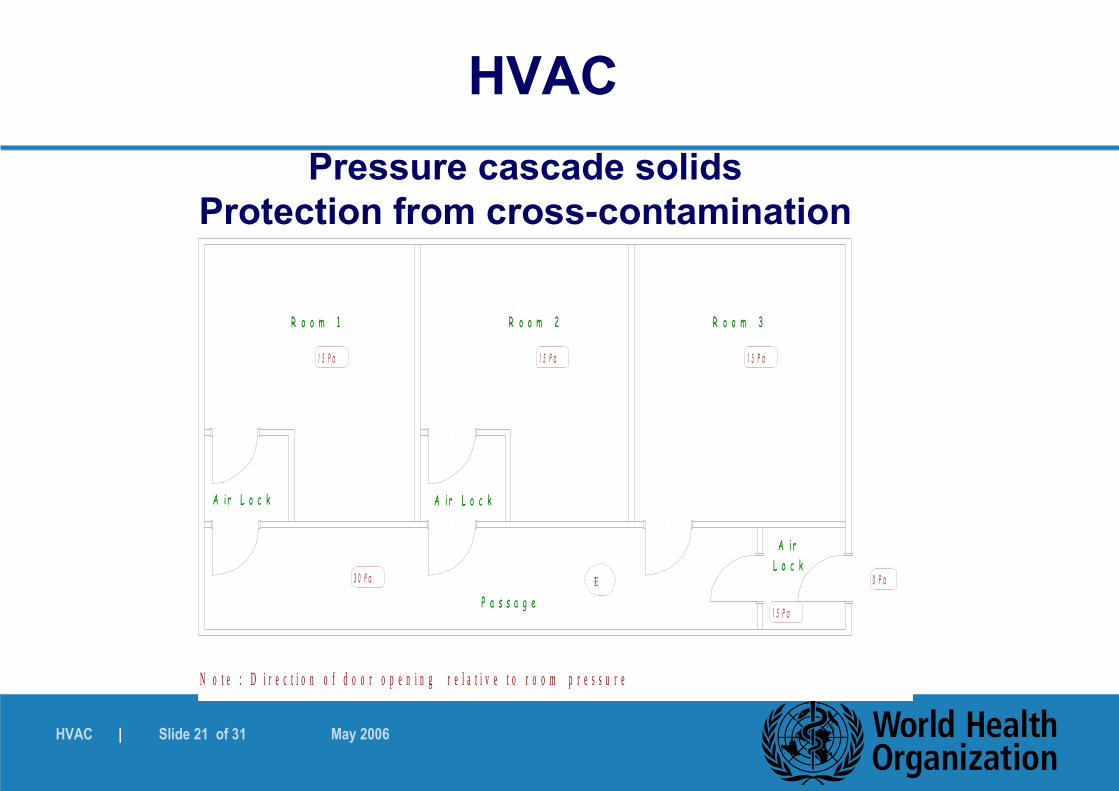
Pressure cascade solidsProtection from cross-contamination
Note : Direction of door opening relative to room pressure 15 Pa15 Pa15 P aE30 PaPassage 0 PaAirLock Room 3 Room 2 Room 115 PaAir LockAir Lock
N o t e : D i r e c t i o n o f d o o r o p e n i n g r e l a t i v e t o r o o m p r e s s u r e
1 5 P a
1 5 P a1 5 P a
E3 0 P a
P a s s a g e0 P a
A i rL o c k
R o o m 3 R o o m 2 R o o m 1
1 5 P a
A i r L o c kA i r L o c k
HVAC

HVAC | Slide 22 of 31 May 2006
HVAC
Physical barrier concept
In some cases, impervious barriers are used to prevent cross-contamination
Spot ventilation
Capture hoods
4.5.27 – 4.5.28
HVAC | Slide 23 of 31 May 2006
HVAC
Temperature and relative humidity (RH)
Controlled, monitored and recorded where relevant
Materials and product requirements, operator comfort
Minimum and maximum limits
Premises design appropriate, e.g. low humidity areas, well sealed and airlocks where necessary
HVAC design – also prevent moisture migration4.6.1. – 4.6.6
HVAC | Slide 24 of 31 May 2006
HVAC
Temperature and relative humidity (RH) (2)
Remove moisture, or add moisture as necessary
Dehumidification– Refrigerated dehumidifiers with cooling media
– Chemical dehumidifiers
Humidifiers should not be sources of contamination
– Use of pure steam or clean steam
– No chemicals added to boiler system if these can have a detrimental effect on product (e.g. some corrosion inhibitors/chelating agents)
4.6.7. – 4.6.11
HVAC | Slide 25 of 31 May 2006
HVAC
Temperature and relative humidity (RH) (3)
Humidification systems: Design should be such that the system does not become the source of contamination:
No accumulation of condensate
Avoid evaporative systems, atomizers, water-mist sprays
Suitable duct material, insulation of cold surfaces
Air filters not immediately downstream of humidifiers
Chemical driers – used if not sources of contamination
4.6.12. – 4.6.18

HVAC | Slide 26 of 31 May 2006
HVAC
Dust Control
Dust and vapour removed at source
Point of use extraction – fixed points or movable hood – plus general directional airflow in room
Ensure sufficient transfer velocity to prevent dust settling in ducting
Risk analysis – airflow direction, hazards, operator
5.1. – 5.7
HVAC | Slide 27 of 31 May 2006
HVAC
Dust Control (2)
Normally air supplied through ceiling diffusers, and air extracted from low level – aids flushing effect
Extraction of vapours – consider density of vapour
Handling harmful products – additional steps needed– e.g. barrier technology, glove boxes
– totally enclosed garments with air-breathing systems
Fresh air rate supply– comfort, odour and fume removal, leakage, pressure control, etc.
5.8. – 5.14
HVAC | Slide 28 of 31 May 2006
HVAC
Protection of the environment (Exhaust air dust)
Exhaust air from equipment and some areas of production carry heavy loads of dust (e.g. FBD, coating, weighing)
Filtration needed to prevent ambient contamination
Not highly potent material
– EN779 F9 filter recommended
Harmful substances (e.g. hormones)– EN1822 H12 (HEPA) filter recommended
– In some cases two banks of HEPA filters
– Safe change filter housings ("bag-in bag-out" filters)6.1.1 – 6.1.5

HVAC | Slide 29 of 31 May 2006
HVAC
Protection of the environment (Exhaust air dust) (2)
Filter banks provided with pressure differential indication gauges
Limits indicated, results monitored at regular intervals– Manual, Building Management Systems, Building
Automated Systems, System Control and Data Acquisition systems
Automated systems provided with alarm or similar system to indicate OOS
6.1.6 – 6.1.10
HVAC | Slide 30 of 31 May 2006
HVAC
Protection of the environment (Exhaust air dust) (3)
Reverse pulse dust collectors– Should be equipped with cartridge filters with compressed air
lance,– Continuous operation – no interruption of airflow
Dust collectors with mechanical shakers– Used in a manner not to become source of contamination– Switched off at times resulting in loss of airflow, and disruption of
pressure cascade
Wet scrubbers– Use suitable drainage system for dust slurry
Determine exhaust air quality to verify filtration efficiency
6.1.11 – 6.1.15
HVAC | Slide 31 of 31 May 2006
HVAC
Protection of the environment (Fume removal)
Appropriate design, installation, and operation of fume, dust, effluent control
Wet scrubbers
– Added chemicals for increased adsorption efficiency
Deep bed scrubbers
– Activated carbon or chemical adsorption granular media
– Specific to type of effluent
– Type and volume prepared6.2.1 – 6.2.5