Embed Size (px)
Citation preview
The Creately Blog
Features Examples Pricing Community
1 March 2012 Nishadha
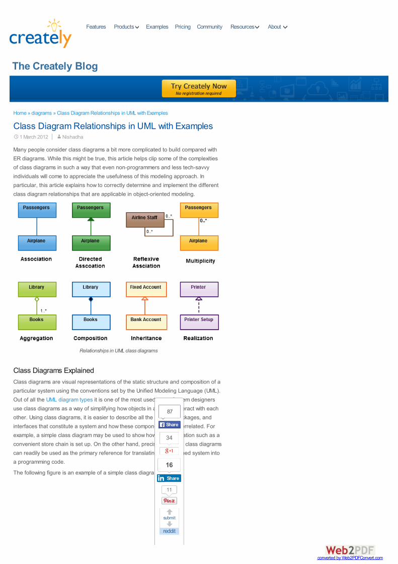
Many people consider class diagrams a bit more complicated to build compared withER diagrams. While this might be true, this article helps clip some of the complexitiesof class diagrams in such a way that even non-programmers and less tech-savvyindividuals will come to appreciate the usefulness of this modeling approach. Inparticular, this article explains how to correctly determine and implement the differentclass diagram relationships that are applicable in object-oriented modeling.
Relationships in UML class diagrams
Class Diagrams ExplainedClass diagrams are visual representations of the static structure and composition of aparticular system using the conventions set by the Unified Modeling Language (UML).Out of all the UML diagram types it is one of the most used ones. System designersuse class diagrams as a way of simplifying how objects in a system interact with eachother. Using class diagrams, it is easier to describe all the classes, packages, andinterfaces that constitute a system and how these components are interrelated. Forexample, a simple class diagram may be used to show how an organization such as aconvenient store chain is set up. On the other hand, precisely detailed class diagramscan readily be used as the primary reference for translating the designed system intoa programming code.
The following figure is an example of a simple class diagram:
Home » diagrams » Class Diagram Relationships in UML with Examples
Class Diagram Relationships in UML with Examples
AboutProducts Resources
34
submit
87
ShareShare
16
ShareShare
11
converted by Web2PDFConvert.com
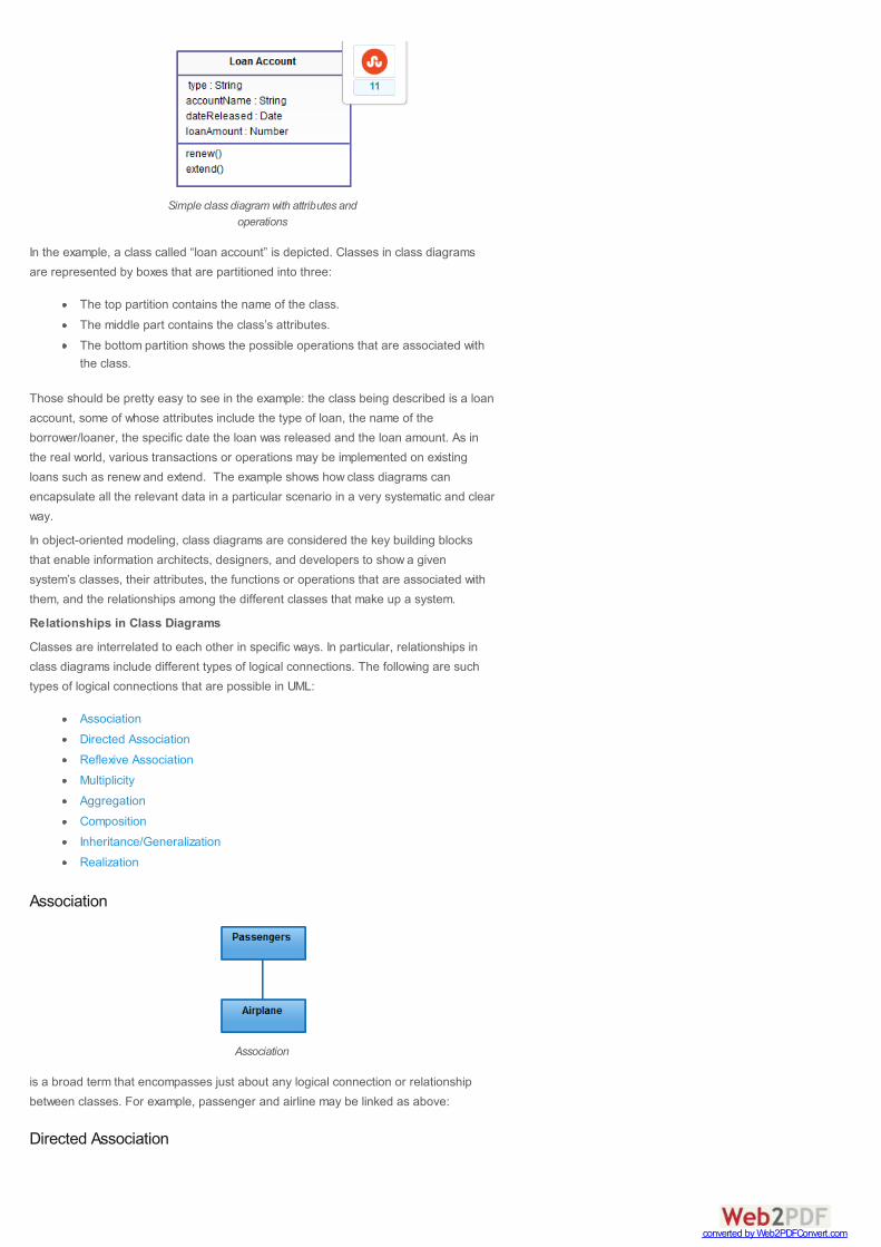
Simple class diagram with attributes andoperations
In the example, a class called “loan account” is depicted. Classes in class diagramsare represented by boxes that are partitioned into three:
The top partition contains the name of the class.The middle part contains the class’s attributes.The bottom partition shows the possible operations that are associated withthe class.
Those should be pretty easy to see in the example: the class being described is a loanaccount, some of whose attributes include the type of loan, the name of theborrower/loaner, the specific date the loan was released and the loan amount. As inthe real world, various transactions or operations may be implemented on existingloans such as renew and extend. The example shows how class diagrams canencapsulate all the relevant data in a particular scenario in a very systematic and clearway.
In object-oriented modeling, class diagrams are considered the key building blocksthat enable information architects, designers, and developers to show a givensystem’s classes, their attributes, the functions or operations that are associated withthem, and the relationships among the different classes that make up a system.
Relationships in Class Diagrams
Classes are interrelated to each other in specific ways. In particular, relationships inclass diagrams include different types of logical connections. The following are suchtypes of logical connections that are possible in UML:
AssociationDirected AssociationReflexive AssociationMultiplicityAggregationCompositionInheritance/GeneralizationRealization
Association
Association
is a broad term that encompasses just about any logical connection or relationshipbetween classes. For example, passenger and airline may be linked as above:
Directed Association
11
converted by Web2PDFConvert.com
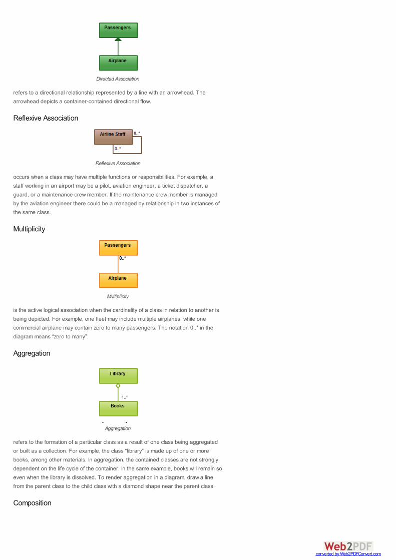
Directed Association
refers to a directional relationship represented by a line with an arrowhead. Thearrowhead depicts a container-contained directional flow.
Reflexive Association
Reflexive Association
occurs when a class may have multiple functions or responsibilities. For example, astaff working in an airport may be a pilot, aviation engineer, a ticket dispatcher, aguard, or a maintenance crew member. If the maintenance crew member is managedby the aviation engineer there could be a managed by relationship in two instances ofthe same class.
Multiplicity
Multiplicity
is the active logical association when the cardinality of a class in relation to another isbeing depicted. For example, one fleet may include multiple airplanes, while onecommercial airplane may contain zero to many passengers. The notation 0..* in thediagram means “zero to many”.
Aggregation
Aggregation
refers to the formation of a particular class as a result of one class being aggregatedor built as a collection. For example, the class “library” is made up of one or morebooks, among other materials. In aggregation, the contained classes are not stronglydependent on the life cycle of the container. In the same example, books will remain soeven when the library is dissolved. To render aggregation in a diagram, draw a linefrom the parent class to the child class with a diamond shape near the parent class.
Composition
converted by Web2PDFConvert.com
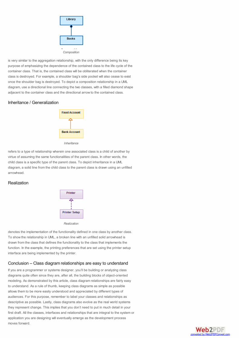
Composition
is very similar to the aggregation relationship, with the only difference being its keypurpose of emphasizing the dependence of the contained class to the life cycle of thecontainer class. That is, the contained class will be obliterated when the containerclass is destroyed. For example, a shoulder bag’s side pocket will also cease to existonce the shoulder bag is destroyed. To depict a composition relationship in a UMLdiagram, use a directional line connecting the two classes, with a filled diamond shapeadjacent to the container class and the directional arrow to the contained class.
Inheritance / Generalization
Inheritance
refers to a type of relationship wherein one associated class is a child of another byvirtue of assuming the same functionalities of the parent class. In other words, thechild class is a specific type of the parent class. To depict inheritance in a UMLdiagram, a solid line from the child class to the parent class is drawn using an unfilledarrowhead.
Realization
Realization
denotes the implementation of the functionality defined in one class by another class.To show the relationship in UML, a broken line with an unfilled solid arrowhead isdrawn from the class that defines the functionality to the class that implements thefunction. In the example, the printing preferences that are set using the printer setupinterface are being implemented by the printer.
Conclusion – Class diagram relationships are easy to understandIf you are a programmer or systems designer, you’ll be building or analyzing classdiagrams quite often since they are, after all, the building blocks of object-orientedmodeling. As demonstrated by this article, class diagram relationships are fairly easyto understand. As a rule of thumb, keeping class diagrams as simple as possibleallows them to be more easily understood and appreciated by different types ofaudiences. For this purpose, remember to label your classes and relationships asdescriptive as possible. Lastly, class diagrams also evolve as the real world systemsthey represent change. This implies that you don’t need to put in much detail in yourfirst draft. All the classes, interfaces and relationships that are integral to the system orapplication you are designing will eventually emerge as the development processmoves forward.
converted by Web2PDFConvert.com
← Use Shared Projects as Libraries for FasterDiagramming
→Creately Diagramming Plugin Now Supports
FogBugz on Demand
To make your job a lot easier, you can check out the online diagramming applicationoffered on the Creately site. Besides being easy to use, the platform provides acomprehensive range of UML templates among other diagramming services. Inaddition, the platform supports collaboration and may be integrated into an existingcompany wiki or Intranet to keep diagrams well documented and updated. Having sucha tool on your side will greatly improve your company’s development initiatives and willhelp your team meet its targets.
Now that you understand class diagram relationships it’s time to draw some, getstarted with this easy to use class diagram templates.
References:
1. UML basics: The class diagram An introduction to structure diagrams in UML 2 byDonald Bell
2. Class diagram as published on the Wikipedia website
3. The UML Class Diagram Part 1 as published in the website developer.com
4. The Class Diagram from Visual Case Tool – UML Tutorial as published on VisualCase website
5. Associations as published on the Sybase website
More related articles...
Download article as PDF
Tags : aggregation, association, class diagram relationships, class diagrams,inheritance, realization, UML
About the Author
UnderstandingUML ClassDiagramRelationships
Class DiagramTemplates toInstantly CreateClass Diagrams
Guidelines forUML ClassDiagrams ~ part1
Creately UMLOnline KeepsGetting Better
PART 1: Whattype of UMLdiagram shouldyou be using?
converted by Web2PDFConvert.com

About NishadhaSoftware engineer turned tech evangelist. I handle marketing stuff hereat Creately including writing blog posts and handling social mediaaccounts. In my spare time I love to read and travel. Check out mypersonal blog Rumbling Lankan where I write about online marketing
stuff. View all posts by Nishadha →
32 thoughts on “Class Diagram Relationships in UML with Examples”
noway
24 April 2012 at 6:22 am
aggregation an composition in a class diagramm are shown by the diamond onthe aggregate calss side . It means the “Library” calss will have the diamondand not the “Books”. Very common mistake, most if the beginners make.thanks noway
Reply
Nishadha
24 April 2012 at 3:43 pm
Hi noway,You’re correct. We have corrected the mistake now. Thanks for taking the time topoint that out.
Reply
iraj osolli
10 May 2012 at 12:18 am
thank uvery nice…………..
Reply
WimalPerera
10 May 2012 at 5:57 pm
Hi Nishi, its a great blog man. I just accidently came across this when browsingweb.Great work!! Keep it up.
Reply
RajasekharReddy
12 September 2012 at 8:50 pm
Hi Nishada,your explanation is very clear to understand,can you send me theclass modelling example of hospitality management system.
Reply
Nishadha
13 September 2012 at 3:33 pm
Hi Rajasekhar,You can browse through our UML class diagrams examples and find a goodone that matches your needs.
Reply
sid
25 September 2012 at 8:52 pm
Hi Nishadha, your explanation was very informative,can you send me the classmodellind diagram for bill splitting applications
Reply
converted by Web2PDFConvert.com

amal
31 October 2012 at 12:49 am
nice effort to help people… i appreciate
Reply
Agecoat
5 January 2013 at 1:41 am
Your explanation of the reflexive association strikes me as odd.Your explation of reflexive depicts an association class between ‘airport’ and‘staff’ in which the association depicts the ‘multiple roles’ of the particular ‘staff’in regard to the ‘airport’.The reflexive association, to me, depicts the situation of a relation betweenequally typed instances, for example, like in a mesh network or in a(genealogical) parent – child construction of type Person.Also consider adding the association class as a conceptual class relationshipconstruct.
Reply
Nishadha
7 January 2013 at 5:27 pm
Hi Agecoat,Thanks for visiting and leaving a comment. I think the example is valid but abetter job could be done by adding an example. I have added an example tomake it more clear.
Reply
aliy
24 May 2014 at 3:01 am
thank for your effort i need some help in terms of this diagram am a studentat kampala uganda i have a scenario but i want come along with classdiagram , state chart, use case diagram and collaboration with sequencediagram i need your assistance,1CASE STUDYMental Health Care Patient Management System(MHCPMS)This case study is based on a real system that is in use in a number ofhospitals.For reasons of commercial confidentiality, I have changed the name of thesystem and have not included information about any specific systemfeatures.1. BackgroundA regional health authority wishes to procure an information system to helpmanage the care of patients suffering from mental health problems. Theoverallgoals of the system are twofold:1. To generate management information that allows health service managerstoassess performance against local and government targets.2. To provide medical staff with timely information to facilitate the treatmentof patients.The health authority has a number of clinics that patients may attend indifferent hospitals and in local health centres. Patients need not alwaysattendthe same clinic and some clinics may support ‘drop in’ as well as pre-arrangedappointments.The nature of mental health problems is such that patients are oftendisorganised so may miss appointments, deliberately or accidentally loseprescriptions and medication, forget instructions and make unreasonabledemands on medical staff. In a minority of cases, they may be a danger tothemselves or to other people. They may regularly change address and maybehomeless on a long-term or short-term basis. Where patients aredangerous,
converted by Web2PDFConvert.com

they may need to be ‘sectioned’ – confined to a secure hospital for treatmentand observation.Users of the system include clinical staff (doctors, nurses, health visitors),receptionists who make appointments and medical records staff. Reportsaregenerated for hospital management by medical records staff. Managementhaveno direct access to the system.The system is affected by two pieces of legislation (in the UK, Acts ofParliament). These are the Data Protection Act that governs the confidentialityMHCPMS Case Study 2of personal information and the Mental Health Act that governs thecompulsorydetention of patients deemed to be a danger to themselves or others.The system is NOT a complete medical records system where all informationabout a patients’ medical treatment is maintained. It is solely intended tosupport mental health care so if a patient is suffering from some otherunrelatedcondition (such as high blood pressure) this would not be formally recordedinthe system.
Reply
adeyeni
17 June 2014 at 1:25 am
mail me lets discuss, im also doin an hospital management system
Reply
AbhasTandon
12 February 2013 at 1:39 am
Thanks a lot.. I was little confused about simple and directed associations butyour post cleared my doubt.
Reply
satish
14 March 2013 at 11:56 pm
hey hii can you help us out in making er diagram for our project…
Reply
Nishadha
15 March 2013 at 9:07 pm
Hi Satish,Maybe you can refer our ER diagram tutorial to help with your project.
Reply
AkashAgrawal
12 April 2013 at 7:46 am
nice points which u have clear to me….can u have explain class diagram ofonline examination….
Reply
UzmaPathan
7 May 2013 at 4:45 pm
Hi, I have a query. Can realization relationship exist between a Package and anInterface? Can we draw a realization relation (Empty head arrow) between aPackage and an Interface in UML?
Reply
converted by Web2PDFConvert.com

Saad Malik
30 May 2013 at 9:31 am
Out of curiosity, in the Airplane to Passengers Multiplicity example, shouldn’t thisrelationship be a Aggregation? In general, could you please give an example ofwhen an association is more apt than an aggregation/composition with multipleobjects?
Reply
Prashanth
24 June 2013 at 2:52 pm
The example you’ve given for inheritance/generalization should be the other wayround. Bank Account should be the Parent. Fixed, Savings accounts should bethe children. Bank account will hold the general attributes/ methods where asthe Fixed account will have specific attributes/ methods inheriting the rest fromthe Bank account.
Reply
priyansh
13 August 2013 at 3:42 am
how do i show primary key in class diagram????
Reply
mcr1234
20 August 2013 at 1:41 pm
very useful, thank you very much ̂ ^
Reply
Thashreef
22 August 2013 at 2:44 am
What is the Relationship between Employee and Employee_Dependent Class
Reply
accountingsoftware
3 September 2013 at 8:17 pm
Large number of individuals looks for these details but they will not get effectiveone. I truly several thanks for discussing it
Reply
DarrenBruce
25 September 2013 at 8:04 pm
Good summary, just one thing, you have the wrong example in Composition.You should Library and Books again (as per Aggregation) and then talk aboutShoulder Bag and Shoulder Bag Pocket in the text. Basically you need to relabelthe diagram example. Cheers
Reply
Blazyprince
23 January 2014 at 11:10 am
on Directed association ,how does planer be the contained ofpassenger(container) I think it is wrong if not explain to me please!!!
Reply
26 February 2014 at 4:15 am
Interesting the concept of aggregation and composition. Got few insights more
converted by Web2PDFConvert.com

Name *
Email *
Website
Leave a Reply
Your email address will not be published. Required fields are marked *
Jimmie to enrich my point of view frame.Thanks fir sharing Nishadha, have a nice day.Jim
Reply
aya
31 March 2014 at 10:26 am
can you tell me more examples with explanations
Reply
yousuf
2 April 2014 at 2:08 pm
in composition diagram above, do you think the books wouldn’t survive thelibrary-death??. A more fitting example would be human and leg OR bulb andfilament OR current and voltage, etc.
Reply
Mohsen
2 July 2014 at 10:26 am
very good but, you can summarize your words in few words
Reply
MananaDero
1 August 2014 at 9:45 pm
thks so much.i got to understand class diagrams the lay man’s way.big up
Reply
shereeff
31 December 2014 at 7:09 pm
Thanks you so much
Reply
indhumathi
17 February 2015 at 3:34 pm
explanation is good and when u give with example it will be easy forbeginners………
Reply
converted by Web2PDFConvert.com
Comment
You may use these HTML tags and attributes: <a href="" title=""> <abbr title="">
<acronym title=""> <b> <blockquote cite=""> <cite> <code> <del datetime=""> <em> <i> <q
cite=""> <strike> <strong>
Post Comment
Confirm you are NOT a spammer
Notify me of replies to my commentThis blog uses premium CommentLuv which allows you to put yourkeywords with your name if you have had 9 approved comments. Useyour real name and then @ your keywords (maximum of 3)
About Creately
Frustrated with Visio? Creately is a web based diagramming software that's superior to Visio in many aspects. Use it to draw flowcharts, UML, mind maps and much moretogether with your friends.
Learn more about Creately
Search the Blog
Search …
Recent Posts
15 Tools to Launch Your Startup + Bonus Tips
Why People Miss Deadlines and How to Avoid Missing Them
Achieving User Experience in Website Builders
New Creately UI Experience for Confluence and JIRA Users
Use Case Diagram Tutorial ( Guide with Examples )
Useful Links
Flowchart Software
UML Diagram Software
Org Chart Software
converted by Web2PDFConvert.com

Creately
Creately Blog
Support
Terms of Service
Privacy
Resellers
Press Kit
Business / User InterfaceDiagrams
Online Flowchart Software
Organizational Chart Software
Mind Mapping Software
SWOT Analysis Software
Online Wireframe Software
Site Map drawing Software
Gantt Charts Drawing Software
Visio Alternative Online
Software and SystemDiagrams
UML Diagrams Creator
UML Sequence Diagrams
Use Case Diagrams
Class Diagrams Creator
Database Design Software
Venn Diagram Maker
Network Diagram Software
Educational Diagrams Creator
More
Copyright © 2008-2015 Cinergix Pty. Ltd. All Rights Reserved.
Venn Diagram Maker
Network Diagram Software
Guest Posting Guidelines
Recent Posts
15 Tools to Launch Your Startup +
Bonus Tips
Why People Miss Deadlines and How
to Avoid Missing Them
Achieving User Experience in Website
Builders
New Creately UI Experience for
Confluence and JIRA Users
Use Case Diagram Tutorial ( Guide
with Examples )
converted by Web2PDFConvert.com