Embed Size (px)
Citation preview

CONTENTS
dummyheaddummyhead
GENERAL INFORMATION 1
BODY PANELS/EXHAUST SYSTEM 2
MAINTENANCE 3
PGM-FI SYSTEM 4
IGNITION SYSTEM 5
ELECTRIC STARTER SYSTEM 6
FUEL SYSTEM 7
LUBRICATION SYSTEM 8
CYLINDER HEAD/VALVES 9
CYLINDER/PISTON 10
CLUTCH/GEARSHIFT LINKAGE 11
ALTERNATOR/STARTER CLUTCH 12
CRANKCASE/TRANSMISSION/CRANKSHAFT 13
ENGINE REMOVAL/INSTALLATION 14
FRONT WHEEL/SUSPENSION/STEERING 15
REAR WHEEL/SUSPENSION 16
HYDRAULIC BRAKE 17
BATTERY/CHARGING SYSTEM 18
LIGHTS/METERS/SWITCHES 19
WIRING DIAGRAMS 20
INDEX
61K26000.book Page 4 Friday, July 12, 2013 3:51 PM

MEMO
dummyheaddummyhead
61K26000.book Page 5 Friday, July 12, 2013 3:51 PM

0-1
dummyheaddummyhead
HOW TO USE THIS MANUALHOW TO USE THIS MANUAL
A Few Words About SafetyService InformationThe service and repair information contained in this manual is intended for use by qualified, professional technicians. Attemptingservice or repairs without the proper training, tools, and equipment could cause injury to you or others. It could also damage thevehicle or create an unsafe condition.
This manual describes the proper methods and procedures for performing service, maintenance and repairs. Some proceduresrequire the use of specially designed tools and dedicated equipment. Any person who intends to use a replacement part, serviceprocedure or a tool that is not recommended by Honda, must determine the risks to their personal safety and the safe operation ofthe vehicle.
If you need to replace a part, use Genuine Honda parts with the correct part number or an equivalent part. We strongly recommendthat you do not use replacement parts of inferior quality.
For Your Customer’s SafetyProper service and maintenance are essential to the customer’s safety and the reliability of the vehicle. Any error or oversight whileservicing a vehicle can result in faulty operation, damage to the vehicle, or injury to others.
For Your SafetyBecause this manual is intended for the professional service technician, we do not provide warnings about many basic shop safetypractices (e.g., Hot parts–wear gloves). If you have not received shop safety training or do not feel confident about your knowledgeof safe servicing practice, we recommended that you do not attempt to perform the procedures described in this manual.
Some of the most important general service safety precautions are given below. However, we cannot warn you of every conceivable hazard that can arise in performing service and repair procedures. Only you can decide whether or not you shouldperform a given task.
Important Safety PrecautionsMake sure you have a clear understanding of all basic shop safety practices and that you are wearing appropriate clothing andusing safety equipment. When performing any service task, be especially careful of the following:
• Read all of the instructions before you begin, and make sure you have the tools, the replacement or repair parts, and the skillsrequired to perform the tasks safely and completely.
• Protect your eyes by using proper safety glasses, goggles or face shields any time you hammer, drill, grind, pry or work aroundpressurized air or liquids, and springs or other stored-energy components. If there is any doubt, put on eye protection.
• Use other protective wear when necessary, for example gloves or safety shoes. Handling hot or sharp parts can cause severeburns or cuts. Before you grab something that looks like it can hurt you, stop and put on gloves.
• Protect yourself and others whenever you have the vehicle up in the air. Any time you lift the vehicle, either with a hoist or a jack,make sure that it is always securely supported. Use jack stands.
Make sure the engine is off before you begin any servicing procedures, unless the instruction tells you to do otherwise. This willhelp eliminate several potential hazards:
• Carbon monoxide poisoning from engine exhaust. Be sure there is adequate ventilation whenever you run the engine. • Burns from hot parts or coolant. Let the engine and exhaust system cool before working in those areas. • Injury from moving parts. If the instruction tells you to run the engine, be sure your hands, fingers and clothing are out of the way.
Gasoline vapors and hydrogen gases from batteries are explosive. To reduce the possibility of a fire or explosion, be careful whenworking around gasoline or batteries.
• Use only a nonflammable solvent, not gasoline, to clean parts. • Never drain or store gasoline in an open container. • Keep all cigarettes, sparks and flames away from the battery and all fuel-related parts.
Improper service and repairs can create an unsafe condition that can cause your customer to be seriously hurt or killed.
Follow the procedures and precautions in this manual and other service materials carefully.
Failure to properly follow instructions and precautions can cause you to be seriously hurt or killed.
Follow the procedures and precautions in this manual carefully.
61K26000.book Page 1 Friday, July 12, 2013 3:51 PM

0-2
dummyheaddummyhead
HOW TO USE THIS MANUAL
How To Use This ManualThis manual describes the service procedures for the GROM125.
Sections 1 and 3 apply to the whole vehicle. Section 2 illustrates procedures for removal/installation of components that may berequired to perform service described in the following sections.Section 4 through 20 describe parts of the motorcycle, grouped according to location.
Follow the Maintenance Schedule recommendations to ensure that the vehicle is in peak operating condition.Performing the first scheduled maintenance is very important. It compensates for the initial wear that occurs during the break-inperiod.
Find the section you want on this page, then turn to the table of contents on the first page of the section.
Most sections start with an assembly or system illustration, service information and troubleshooting for the section. The subsequentpages give detailed procedure.
As you read this manual, you will find information that is preceded by a symbol. The purpose of this message is to help prevent damage to your vehicle, other property, or the environment.
© Honda Motor Co., Ltd.SERVICE PUBLICATION OFFICE
Date of Issue: August., 2013
Your safety, and the safety of others, is very important. To help you make informed decisions we have provided safety messages and other information throughout this manual. Of course, it is not practical or possible to warn you about all the hazards associated with servicing this vehicle.You must use your own good judgement.You will find important safety information in a variety of forms including: • Safety Labels – on the vehicle • Safety Messages – preceded by a safety alert symbol and one of three signal words, DANGER, WARNING, or CAUTION.
These signal words mean:
You WILL be KILLED or SERIOUSLY HURT if you don’t follow instructions.
You CAN be KILLED or SERIOUSLY HURT if you don’t follow instructions.
You CAN be HURT if you don’t follow instructions. • Instructions – how to service this vehicle correctly and safely.
ALL INFORMATION, ILLUSTRATIONS, DIRECTIONS AND SPECIFICATIONS INCLUDED IN THIS PUBLICATION ARE BASED ON THE LATEST PRODUCT INFORMATION AVAILABLE AT THE TIME OF APPROVAL FOR PRINTING. Honda Motor Co., Ltd. RESERVES THE RIGHT TO MAKE CHANGES AT ANY TIME WITHOUT NOTICE AND WITHOUT INCURRING ANY OBLIGATION WHATSOEVER. NO PART OF THIS PUBLICATION MAY BE REPRODUCED WITHOUT WRITTEN PERMISSION. THIS MANUAL IS WRITTEN FOR PERSONS WHO HAVE ACQUIRED BASIC KNOWLEDGE OF MAINTENANCE ON Honda MOTORCYCLES, MOTOR SCOOTERS OR ATVS.
61K26000.book Page 2 Friday, July 12, 2013 3:51 PM

0-3
dummyheaddummyhead
HOW TO USE THIS MANUAL
SYMBOLSThe symbols used throughout this manual show specific service procedures. If supplementary information is required pertaining tothese symbols, it would be explained specifically in the text without the use of the symbols.
Replace the part(s) with new one(s) before assembly.
Use the recommend engine oil, unless otherwise specified.
Use molybdenum oil solution (mixture of the engine oil and molybdenum grease in a ratio of 1:1).
Use multi-purpose grease (lithium based multi-purpose grease NLGI #2 or equivalent).
Use molybdenum disulfide grease (containing more than 3% molybdenum disulfide, NLGI #2 or equivalent).Example: • Molykote® BR-2 plus manufactured by Dow Corning U.S.A. • Multi-purpose M-2 manufactured by Mitsubishi Oil, Japan
Use molybdenum disulfide paste (containing more than 40% molybdenum disulfide, NLGI #2 or equivalent).Example: • Molykote® G-n Paste manufactured by Dow Corning U.S.A. • Honda Moly 60 (U.S.A. only) • Rocol ASP manufactured by Rocol Limited, U.K. • Rocol Paste manufactured by Sumico Lubricant, Japan
Use silicone grease.
Apply a locking agent. Use a medium strength locking agent unless otherwise specified.
Apply sealant.
Use DOT 3 or DOT 4 brake fluid. Use the recommended brake fluid unless otherwise specified.
Use fork or suspension fluid.
61K26000.book Page 3 Friday, July 12, 2013 3:51 PM

1-1
1
dummytext
1. GENERAL INFORMATION
SERVICE RULES ··········································1-2
MODEL IDENTIFICATION ····························1-3
SPECIFICATIONS·········································1-5
TORQUE VALUES ······································1-10
LUBRICATION & SEAL POINTS ··············· 1-13
CABLE & HARNESS ROUTING················· 1-15
TECHNICAL FEATURES···························· 1-23
EMISSION CONTROL SYSTEMS ·············· 1-25
61K26000.book Page 1 Friday, July 12, 2013 3:51 PM

1-2
dummyheaddummyhead
GENERAL INFORMATIONGENERAL INFORMATION
SERVICE RULES1. Use Honda genuine or Honda-recommended parts and lubricants or their equivalents. Parts that do not meet Honda's design
specifications may cause damage to the motorcycle.2. Use the special tools designed for this product to avoid damage and incorrect assembly.3. Use only metric tools when servicing the motorcycle. Metric bolts, nuts and screws are not interchangeable with English
fasteners.4. Install new gaskets, O-rings, cotter pins, and lock plates when reassembling.5. When tightening bolts or nuts, begin with the larger diameter or inner bolt first. Then tighten to the specified torque diagonally in
incremental steps unless a particular sequence is specified.6. Clean parts in cleaning solvent upon disassembly. Lubricate any sliding surfaces before reassembly.7. After reassembly, check all parts for proper installation and operation.8. Route all electrical wires as shown in the Cable and Harness Routing (page 1-15).9. Do not bend or twist control cables. Damaged control cables will not operate smoothly and may stick or bind.
ABBREVIATIONThroughout this manual, the following abbreviations are used to identify the respective parts or systems.
DESTINATION CODEThroughout this manual, the following codes are used to identify individual types for each region.
Abbrev. term Full termCKP sensor Crankshaft Position sensorDLC Data Link ConnectorDTC Diagnostic Trouble CodeECM Engine Control ModuleEOT sensor Engine Oil Temperature sensorIAT sensor Intake Air Temperature sensorMIL Malfunction Indicator LampMCS Motorcycle Communication SystemPGM-FI Programmed Fuel InjectionSCS connector Service Check Short connectorTP sensor Throttle Position sensorVS sensor Vehicle Speed sensor
DESTINATION CODE REGIONAC 50 STATE meets CaliforniaCM Canada
61K26000.book Page 2 Friday, July 12, 2013 3:51 PM
1-3
dummyheaddummyhead
GENERAL INFORMATION
MODEL IDENTIFICATION
61K26000.book Page 3 Friday, July 12, 2013 3:51 PM

1-4
dummyheaddummyhead
GENERAL INFORMATION
SERIAL NUMBERS AND LABELS
Emission information label
Vehicle Identification Number (V.I.N) Engine serial number
Throttle body identification number
Color label
Safety certification label
61K26000.book Page 4 Friday, July 12, 2013 3:51 PM

1-5
dummyheaddummyhead
GENERAL INFORMATION
SPECIFICATIONSGENERAL SPECIFICATIONS
ITEM SPECIFICATIONDIMENSIONS Overall length 1,760 mm (69.3 in)
Overall width 755 mm (29.7 in)Overall height 1,010 mm (39.8 in)Wheelbase 1,200 mm (47.2 in)Seat height 765 mm (30.1 in)Footpeg height 286 mm (11.3 in)Ground clearance 160 mm (6.3 in)Curb weight 102 kg (225 lbs)Maximum weight capacity 140 kg (309 lbs)
FRAME Frame type Back bone typeFront suspension Telescopic forkFront axle travel 100 mm (3.9 in)Rear suspension SwingarmRear axle travel 103 mm (4.1 in)Tire size Front 120/70-12 51L
Rear 130/70-12 56LTire brand Front V119C (VEE RUBBER)
Rear V119C (VEE RUBBER)Front brake Hydraulic single discRear brake Hydraulic single discCaster angle 25° 00’Trail length 81 mm (3.2 in)Fuel tank capacity 5.5 liters (1.45 US gal, 1.21 Imp gal)
ENGINE Cylinder arrangement Single cylinder inclined 80° from verticalBore and stroke 52.4 x 57.9 mm (2.06 - 2.28 in)Displacement 124.9 cm3
Compression ratio 9.3:1 Valve train Chain driven, OHCIntake valve opens at 1.0 mm lift 2° BTDC
closes at 1.0 mm lift 25° ABDCExhaust valve opens at 1.0 mm lift 34° BBDC
closes at 1.0 mm lift 0° TDCLubrication system Forced pressure and wet sumpOil pump type TrochoidCooling system Air cooledAir filtration Viscous paper elementEngine dry weight 23.4 kg (52 lbs)
FUEL DELIVERY SYSTEM
Type PGM-FIThrottle bore 24 mm (1.06 in)
DRIVE TRAIN Clutch system Multi-plate, wetClutch operation system Cable operatingTransmission Constant mesh, 4 speedsPrimary reduction 3.350 (67/20)Final reduction 2.266 (34/15)Gear ratio 1st 2.500 (35/14)
2nd 1.550 (31/20)3rd 1.150 (23/20) 4th 0.923 (24/26)
Gearshift pattern Left foot operated return system,1 - N - 2 - 3 - 4
ELECTRICAL Ignition system Computer-controlled digital transistorized with electric advance
Starting system Electric starter motorCharging system Single phase output alternatorRegulator/rectifier SCR opened, single phase half-wave
rectificationLighting system Alternator
61K26000.book Page 5 Friday, July 12, 2013 3:51 PM

1-6
dummyheaddummyhead
GENERAL INFORMATION
PGM-FI SYSTEM SPECIFICATIONS
IGNITION SYSTEM SPECIFICATIONS
ELECTRIC STARTER SYSTEM SPECIFICATIONSUnit: mm (in)
FUEL SYSTEM SPECIFICATIONS
LUBRICATION SYSTEM SPECIFICATIONSUnit: mm (in)
ITEM SPECIFICATIONSEngine idle speed 1,400 ± 100 min-1 (rpm)IAT sensor resistance (40°C/104°F) 21.2 – 16.4 kΩEOT sensor resistance (20°C/68°F) 2.5 – 2.8 kΩ
(100°C/212°F) 0.21 – 0.22 kΩFuel injector resistance (20°C/68°F) 11 – 13 Ω
ITEM SPECIFICATIONSSpark plug Standard CPR6EA-9 (NGK) U20EPR9 (DENSO)
Optional CPR7EA-9 (NGK) U22EPR9 (DENSO)Spark plug gap 0.8 – 0.9 mm (0.03 - 0.04 in)Ignition coil peak voltage 100 V minimumCKP sensor peak voltage 0.7 V minimumIgnition timing 12° BTDC at idle speed
ITEM STANDARD SERVICE LIMITStarter motor brush length 6.7 – 7.3 (0.26 - 0.29) 3.5 (0.14)
ITEM SPECIFICATIONSThrottle body identification number GQY9AIdle air screw standard opening 2 turns out from the fully seated positionThrottle grip freeplay 2 – 6 mm (0.08 - 0.24 in)Fuel pressure at idle 270 - 323 kPa (2.75 - 3.29 kgf/cm2, 39 - 47 psi)Fuel pump flow (at 12 V) 162 cm3 minimum/10 seconds
ITEM STANDARD SERVICE LIMITEngine oil capacity At draining 0.9 liter (0.96 US Qt, 0.20 Imp gal)
At disassembly 1.1 liters (1.16 US Qt, 0.24 Imp gal)Recommended engine oil Pro Honda GN4 4-stroke oil (U.S.A. &
Canada) or equivalent motorcycle oilAPI service classification: SG or higher (except oils labeled as energy conserving on the circular API service label)JASO T903 standard: MAViscosity: SAE 10W-30
Oil pump rotor Tip clearance 0.15 (0.006)Body clearance 0.15 0.21 (0.006 - 0.008) 0.26 (0.010)Side clearance 0.03 0.09 (0.001 - 0.004) 0.15 (0.006)
61K26000.book Page 6 Friday, July 12, 2013 3:51 PM

1-7
dummyheaddummyhead
GENERAL INFORMATION
CYLINDER HEAD/VALVES SPECIFICATIONSUnit: mm (in)
CYLINDER/PISTON SPECIFICATIONSUnit: mm (in)
ITEM STANDARD SERVICE LIMITCylinder compression 1.1 MPa (11.2 kgf/cm2, 160 psi) at
600 min-1 (rpm) –
Cylinder head warpage – 0.05 (0.002)Camshaft Cam lobe height IN 32.657 – 32.897 (1.2857 - 1.2952) 32.33 (1.2728)
EX 32.481 – 32.721 (1.2788 - 1.2882) 31.78 (1.2512)Valve, valve guide
Valve clearance IN 0.10 ± 0.02 (0.004 ± 0.001) – EX 0.17 ± 0.02 (0.007 ± 0.001) –
Valve stem O.D. IN 4.975 – 4.990 (0.1959 - 0.1965) 4.965 (0.1955)EX 4.955 – 4.970 (0.1951 - 0.1957) 4.945 (0.1947)
Valve guide I.D. IN/EX 5.000 – 5.012 (0.1969 - 0.1973) 5.03 (0.198)Stem-to-guide clearance IN 0.010 – 0.037 (0.0004 - 0.0015) 0.065 (0.003)
EX 0.030 – 0.057 (0.0012 - 0.0022) 0.085 (0.003)Valve guide projection IN/EX 10.1 – 10.3 (0.40 - 0.41) – Valve seat width IN/EX 1.0 (0.04) 1.6 (0.06)
Valve spring free length IN/EX 33.14 (1.305) 31.5 (1.240)Cam chain tensioner
Push rod O.D. 11.985 – 12.000 (0.4718 - 0.4724) 11.94 (0.470)Spring free length 111.3 (4.38) 109 (4.29)
ITEM STANDARD SERVICE LIMITCylinder I.D. 52.405 – 52.415 (2.0632 - 2.0636) 52.445 (2.0648)
Out-of-round – 0.10 (0.004)Taper – 0.10 (0.004)Warpage – 0.05 (0.002)
Piston, piston rings, piston pin
Piston O.D. 52.380 – 52.395 (2.0622 - 2.0628) 52.310 (2.0594)Piston O.D. measurement point 10 mm from bottom of skirt –Piston pin bore I.D. 13.002 – 13.008 (0.5119 - 0.5121) 13.03 (0.5130)Piston pin O.D. 12.994 – 13.000 (0.5116 - 0.5118) 12.98 (0.5110)Piston-to-piston pin clearance 0.002 – 0.014 (0.0001 - 0.0005) 0.05 (0.002)Piston ring-to-ring groove clearance (RIKEN)
Top 0.030 – 0.065 (0.0012 - 0.0026) 0.100 (0.0039)
Second 0.015 – 0.050 (0.0006 - 0.0020) 0.090 (0.0035)
Piston ring-to-ring groove clearance (TEIKOKU)
Top 0.015 – 0.050 (0.0006 - 0.0020) 0.090 (0.0035)
Second 0.015 – 0.050 (0.0006 - 0.0020) 0.090 (0.0035)
Piston ring end gap (RIKEN)
Top 0.10 – 0.25 (0.004 - 0.010) 0.50 (0.020)Second 0.10 – 0.30 (0.004 - 0.012) 0.60 (0.024)Oil (side rail) 0.20 – 0.70 (0.008 - 0.028) 1.10 (0.043)
Piston ring end gap (TEIKOKU)
Top 0.10 – 0.25 (0.004 - 0.010) 0.50 (0.020)Second 0.35 – 0.50 (0.014 - 0.020) 0.75 (0.030)Oil (side rail) 0.10 – 0.35 (0.004 - 0.014) 1.10 (0.043)
Cylinder-to-piston clearance 0.010 – 0.035 (0.0004 - 0.0014) 0.10 (0.004)Connecting rod small end I.D. 13.010 – 13.028 (0.5122 - 0.5129) 13.05 (0.514)Connecting rod-to-piston pin clearance 0.010 – 0.034 (0.0004 - 0.0013) 0.07 (0.003)
61K26000.book Page 7 Friday, July 12, 2013 3:51 PM

1-8
dummyheaddummyhead
GENERAL INFORMATION
CLUTCH/GEARSHIFT LINKAGE SPECIFICATIONSUnit: mm (in)
ALTERNATOR/STARTER CLUTCH SPECIFICATIONSUnit: mm (in)
CRANKCASE/TRANSMISSION/CRANKSHAFT SPECIFICATIONSUnit: mm (in)
FRONT WHEEL/SUSPENSION/STEERING SPECIFICATIONSUnit: mm (in)
ITEM STANDARD SERVICE LIMITManual clutch Disc thickness 2.50 – 2.70 (0.099 - 0.106) 2.2 (0.09)
Plate warpage – 0.20 (0.008)Clutch spring free length 27.4 (1.08) -Clutch outer I.D. 23.000 – 23.013 (0.9055 - 0.9060) 23.06 (0.908)Clutch outer guide I.D. 16.991 – 17.009 (0.6689 - 0.6696) 17.049 (0.6712)
O.D. 22.959 – 22.980 (0.9039 - 0.9047) 22.940 (0.9031)Mainshaft O.D. at clutch outer guide 16.966 – 16.984 (0.6680 - 0.6687) 16.87 (0.66)
ITEM STANDARD SERVICE LIMITStarter driven gear boss O.D. 45.660 – 45.673 (1.7976 - 1.7981) 45.642 (1.7969)
ITEM STANDARD SERVICE LIMITCrankshaft Connecting rod side clearance 0.10 – 0.35 (0.004 - 0.0138) 0.60 (0.024)
Connecting rod radial clearance 0.004 – 0.016 (0.0002 - 0.0006) 0.05 (0.002)Runout – 0.10 (0.004)
Transmission Gear I.D. M2, M3 17.000 – 17.018 (0.6693 - 0.6700) 17.04 (0.671)C1 18.000 – 18.018 (0.7087 - 0.7094) 18.04 (0.710)C4 20.000 – 20.021 (0.7874 - 0.7882) 20.04 (0.789)
Bushing O.D. C1 17.966 – 17.984 (0.7073 - 0.7080) 17.94 (0.706)Bushing I.D. C1 15.000 – 15.018 (0.5906 - 0.5913) 15.04 (0.592)Gear-to-bushing clearance
C1 0.016 – 0.052 (0.0006 - 0.0020) 0.10 (0.004)
Mainshaft O.D. at M3 16.966 – 16.984 (0.6680 - 0.6687) 16.95 (0.667)Countershaft O.D. at C1
bushing 14.966 – 14.984 (0.5892 - 0.5899) 14.95 (0.589)
Gear-to-shaft clearance M3 0.016 – 0.052 (0.0006 - 0.0020) 0.09 (0.004)Bushing-to-shaft clearance C1 0.016 – 0.052 (0.0006 - 0.0020) 0.09 (0.004)
Shift fork/ Shift drum
Shift fork I.D. 10.000 – 10.018 (0.3937 - 0.3944) 10.07 (0.397)Shift fork claw thickness 4.93 – 5.00 (0.194 - 0.197) 4.90 (0.193)Shift fork shaft O.D. 9.986 – 9.995 (0.3931 - 0.3935) 9.93 (0.391)Shift drum journal I.D. Left 24.000 – 24.033 (0.9449 - 0.9462) 24.07 (0.948)
Right 28.000 – 28.021 (1.1024 - 1.1032) 28.08 (1.106)
ITEM STANDARD SERVICE LIMITMinimum tire tread depth – To indicatorCold tire pressure Driver only 200 kPa (2.00 kgf/cm2, 29 psi) –
Driver and passenger 200 kPa (2.00 kgf/cm2, 29 psi) –Axle runout – 0.2 (0.01)Wheel rim runout Radial – 2.0 (0.08)
Axial – 2.0 (0.08)Fork Pipe runout – 0.20 (0.010)
Recommended fork fluid Pro Honda Suspension Fluid SS-8 (10W) –Fluid level 75 (2.95) –Fluid capacity 221.0 ± 1.5 cm3 –
61K26000.book Page 8 Friday, July 12, 2013 3:51 PM

1-9
dummyheaddummyhead
GENERAL INFORMATION
REAR WHEEL/SUSPENSION SPECIFICATIONSUnit: mm (in)
HYDRAULIC BRAKE SPECIFICATIONSUnit: mm (in)
BATTERY/CHARGING SYSTEM SPECIFICATIONS
LIGHTS/METERS/SWITCHES SPECIFICATIONS
ITEM STANDARD SERVICE LIMITMinimum tire tread depth – To indicatorCold tire pressure Driver only 200 kPa (2.00 kgf/cm2, 29 psi) –
Driver and passenger 200 kPa (2.00 kgf/cm2, 29 psi) –Axle runout – 0.2 (0.01)Wheel rim runout Radial – 2.0 (0.08)
Axial – 2.0 (0.08)Drive chain Size/link 420/106 –
Slack 30 – 40 (1.2 - 1.6) –
ITEM STANDARD SERVICE LIMITFront Specified brake fluid Honda DOT 4 brake fluid –
Brake pad wear indicator – To grooveBrake disc thickness 3.3 – 3.7 (0.13 - 0.15) 3.0 (0.12)Brake disc warpage – 0.30 (0.012)Master cylinder I.D. 12.700 – 12.743 (0.5000 - 0.5017) 12.755 (0.5022)Master piston O.D. 12.657 – 12.684 (0.4983 - 0.4994) 12.640 (0.4976)Caliper cylinder I.D. 25.400 – 25.450 (1.0000 - 1.0020) 25.460 (1.0024)Caliper piston O.D. 25.318 – 25.368 (0.9968 - 0.9987) 25.310 (0.9965)
Rear Specified brake fluid DOT 3 or DOT 4 –Brake pad wear indicator – To grooveBrake disc thickness 3.8 – 4.2 (0.15 - 0.17) 3.5 (0.14)Brake disc warpage – 0.30 (0.011)Master cylinder I.D. 14.000 – 14.043 (0.5512 - 0.5529) –Master piston O.D. 13.957 – 13.984 (0.5495 - 0.5506) –Caliper cylinder I.D. 27.000 – 27.050 (1.0630 - 1.0650) –Caliper piston O.D. 26.935 – 26.968 (1.0604 - 1.0617) –
ITEM SPECIFICATIONSBattery Type YTZ5S
Capacity 12 V - 3.5 Ah (10 HR)Current leakage 0.01 mAVoltage(20°C/68°F)
Fully charged 13.0 – 13.2 VNeeds charging Below 12.4 V
Charging current Normal 0.5 A/5 – 10 hQuick 2.5 A/1 h
Alternator Capacity 0.18 kW/5,000 min-1 (rpm)Charging coil resistance (20°C/68°F) 0.2 – 1.0 Ω
ITEM SPECIFICATIONBulbs Headlight (High/Low) 12 V - 35/35 W
Brake/tail light LEDTurn signal light Front 12 V - 21/5 W x 2
Rear 12 V - 21 W x 2 License light 12 V - 5 WMeter light LEDTurn signal indicator LEDHigh beam indicator LEDNeutral indicator LED
Fuse Main fuse 15 ASub fuse 10 A
61K26000.book Page 9 Friday, July 12, 2013 3:51 PM

1-10
dummyheaddummyhead
GENERAL INFORMATION
TORQUE VALUESSTANDARD TORQUE VALUES
ENGINE & FRAME TORQUE VALUES • Torque specifications listed below are for important fasteners. • Others should be tightened to standard torque values listed above.
BODY PANELS/EXHAUST SYSTEM
MAINTENANCE
PGM-FI SYSTEM
FASTENER TYPETORQUE
FASTENER TYPETORQUE
N·m (kgf·m, lbf·ft) N·m (kgf·m, lbf·ft)5 mm bolt and nut 5.2 (0.5, 3.8) 5 mm screw 4.2 (0.4, 3.1)6 mm bolt and nut(Include SH flange bolt)
10 (1.0, 7) 6 mm screw 9.0 (0.9, 6.6)6 mm flange bolt 12 (1.2, 9)
8 mm bolt and nut 22 (2.2, 16) (Include NSHF) and nut10 mm bolt and nut 34 (3.5, 25) 8 mm flange bolt and nut 27 (2.8, 20)12 mm bolt and nut 54 (5.5, 40) 10 mm flange bolt and nut 39 (4.0, 29)
ITEM Q'TYTHREAD TORQUE
REMARKSDIA. (mm) N·m (kgf·m, lbf·ft)
Body cover and tailcover mounting screw 4 4 0.9 (0.1, 0.7)Exhaust pipe cover bolt 2 6 14 (1.4, 10)Exhaust pipe mounting nut 2 8 27 (2.8, 20)Exhaust pipe mounting bolt 1 8 27 (2.8, 20)Exhaust pipe stud bolt 2 8 – See page 2-10Front fender mounting bolt 6 6 12 (1.2, 9)Front cowl mounting bolt 4 6 12 (1.2, 9)Muffler band bolt 1 8 20 (2.0, 15)Muffler mounting bolt 1 8 27 (2.8, 20)Muffler mounting nut 1 8 27 (2.8, 20)Muffler protector bolt 1 6 14 (1.4, 10)Rear fender stay bolt 2 8 31 (3.2, 23)Seat lock bracket bolt 2 6 14 (1.4, 10)Shroud screw 3 5 4.2 (0.4, 3.1)Shroud tapping screw 20 4 0.9 (0.1, 0.7)Sidestand lock nut 1 10 30 (3.1, 22) U-nut Sidestand pivot bolt 1 10 10 (1.0, 7)Sidestand switch bolt 1 6 10 (1.0, 7) ALOC bolt; replace
with a new one.
ITEM Q'TYTHREAD TORQUE
REMARKSDIA. (mm) N·m (kgf·m, lbf·ft)
Air cleaner cover screw 8 5 1.1 (0.1,0.8)Air cleaner element screw 1 5 1.1 (0.1,0.8)Spark plug 1 10 16 (1.6, 12)Crankshaft hole cap 1 30 8.0 (0.8, 5.9)Oil drain bolt 1 12 24 (2.4, 18)
ITEM Q'TYTHREAD TORQUE
REMARKSDIA. (mm) N·m (kgf·m, lbf·ft)
Bank angle sensor mounting nut 2 6 10 (1.0, 7)Fuel injector joint mounting bolt 2 5 12 (1.2, 9)EOT sensor 1 10 14.5 (1.5, 11) Apply engine oil to the
threads and seating surface.
O2 sensor 1 12 24.5 (2.5, 18)
61K26000.book Page 10 Friday, July 12, 2013 3:51 PM

1-11
dummyheaddummyhead
GENERAL INFORMATION
LUBRICATION SYSTEM
FUEL SYSTEM
ENGINE REMOVAL/INSTALLATION
CYLINDER HEAD/VALVES
CYLINDER/PISTON
CLUTCH/GEARSHIFT LINKAGE
ITEM Q'TYTHREAD TORQUE
REMARKSDIA. (mm) N·m (kgf·m, lbf·ft)
Oil centrifugal filter cover bolt 3 6 12 (1.2, 9) Apply locking agent to the threads.
Oil pump assembly bolt 2 5 5.2 (0.5, 3.8)
ITEM Q'TYTHREAD TORQUE
REMARKSDIA. (mm) N·m (kgf·m, lbf·ft)
Fuel filter stay nut 2 6 12 (1.2, 9) For tightening sequence See page 7-5
Fuel pump setting plate nut 2 6 12 (1.2, 9)Fuel pump setting plate special nut 2 6 12 (1.2, 9)Throttle cable stay screw 1 5 3.4 (0.3, 2.5)Connecting hose band screw 1 4 1.5 (0.2, 1.1)
ITEM Q'TYTHREAD TORQUE
REMARKSDIA. (mm) N·m (kgf·m, lbf·ft)
Engine hanger nut (upper) 1 10 54 (5.5, 40)(lower) 1 10 54 (5.5, 40)(front) 1 10 54 (5.5, 40)
Drive sprocket fixing plate bolt 2 6 12 (1.2, 9)Step holder mounting bolt 2 8 31 (3.2, 23)
ITEM Q'TYTHREAD TORQUE
REMARKSDIA. (mm) N·m (kgf·m, lbf·ft)
Cylinder head cap bolt 4 8 24 (2.4, 18) Apply engine oil to the threads and seating surface.
Cam sprocket bolt 1 8 27 (2.8, 20) Apply engine oil to the threads and seating surface.
Tappet adjust nut 2 5 9.0 (0.9, 6.6) Apply engine oil to the threads and seating surface.
Cam chain tensioner sealing bolt 1 14 22 (2.2, 16)Cam chain tensioner arm pivot bolt 1 8 16 (1.6, 12)Cam chain guide lower roller pivot bolt 1 6 10 (1.0, 7)Timing hole cap 1 14 6.0 (0.6, 4.4)Crankshaft hole cap 1 30 8.0 (0.8, 5.9)
ITEM Q'TYTHREAD TORQUE
REMARKSDIA. (mm) N·m (kgf·m, lbf·ft)
Cam chain guide roller pin bolt 1 8 10 (1.0, 7)Cylinder stud bolt 4 8 – See page 10-7
ITEM Q'TYTHREAD TORQUE
REMARKSDIA. (mm) N·m (kgf·m, lbf·ft)
Clutch center lock nut 1 14 64 (6.5, 47) Apply engine oil to the threads and seating surface.
Clutch lifter plate bolt 3 6 12 (1.2, 9)Gearshift cam plate socket bolt 1 6 10 (1.0, 7) Apply locking agent to
the threads.Gearshift return spring pin 1 8 30 (3.1, 22)Oil filter rotor lock nut 1 14 64 (6.5, 47) Apply engine oil to the
threads and seating surface.
Right crankcase cover protector bolt 3 6 12 (1.2, 9)Shift drum stopper arm bolt 1 6 12 (1.2, 9) Apply locking agent to
the threads.
61K26000.book Page 11 Friday, July 12, 2013 3:51 PM
1-12
dummyheaddummyhead
GENERAL INFORMATION
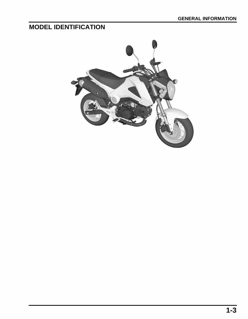
ALTERNATOR
FRONT WHEEL/SUSPENSION/STEERING
REAR WHEEL/SUSPENSION
HYDRAULIC BRAKE
ITEM Q'TYTHREAD TORQUE
REMARKSDIA. (mm) N·m (kgf·m, lbf·ft)
Flywheel nut 1 12 64 (6.5, 47) Apply engine oil to the threads and seating surface.
ITEM Q'TYTHREAD TORQUE
REMARKSDIA. (mm) N·m (kgf·m, lbf·ft)
Front axle nut 1 12 54 (5.5, 40) U-nutFront brake disc bolt 4 8 42 (4.3, 31) ALOC bolt; replace
with a new one.Fork bolt 2 36 30 (3.1, 22)Fork socket bolt 2 8 20 (2.0, 15) Apply locking agent to
the threads.Steering stem nut 1 24 88 (9.0, 65) See page 15-22Steering stem adjusting nut 1 26 1.5 (0.2, 1.1) See page 15-22Top bridge pinch bolt 2 8 27 (2.8, 20)Bottom bridge pinch bolt 4 8 27 (2.8, 20)Handlebar holder bolt 2 8 27 (2.8, 20)Handlebar holder mounting nut 2 8 27 (2.8, 20)Handlebar weight screw 2 6 9.0 (0.9, 6.6) ALOC screw; replace
with a new one.Left handlebar switch screw 2 5 2.5 (0.3, 1.8)Right handlebar switch screw 2 5 2.5 (0.3, 1.8)Clutch lever pivot bolt 1 6 1.0 (0.1, 0.7)Clutch lever pivot nut 1 6 5.9 (0.6, 4.4)
ITEM Q'TYTHREAD TORQUE
REMARKSDIA. (mm) N·m (kgf·m, lbf·ft)
Rear axle nut 1 12 59 (6.0, 44) U-nutDriven sprocket nut 4 8 32 (3.3, 24) U-nutRear brake disc bolt 4 8 42 (4.3, 31) ALOC bolt; replace
with a new one.Shock absorber upper mounting nut 1 10 44 (4.5, 32) U-nutShock absorber lower mounting nut 1 10 44 (4.5, 32) U-nutSwingarm pivot nut 1 12 54 (5.5, 40) U-nutDrive chain slider screw 2 5 6.0 (0.6, 4.4)Driven sprocket stud bolt 4 8 – See page 16-7
ITEM Q'TYTHREAD TORQUE
REMARKSDIA. (mm) N·m (kgf·m, lbf·ft)
Brake hose oil bolt 4 10 34 (3.5, 25)Master cylinder reservoir cover screw 4 4 1.5 (0.2, 1.1)Front brake light switch screw 1 4 1.2 (0.1, 0.2)Brake lever pivot bolt 1 6 1.0 (0.1, 0.7)Brake lever pivot nut 1 6 5.9 (0.6, 4.4)Front brake caliper mounting bolt 2 8 30 (3.1, 22) ALOC bolt; replace
with a new one.Front brake caliper pin bolt 1 8 17 (1.7, 13)Brake pad hanger pin 2 10 17 (1.7, 13)Brake caliper bleed valve 2 8 5.4 (0.6, 4.0)Rear master cylinder push rod lock nut 1 8 17 (1.7, 13)Rear master cylinder hose joint screw 1 4 1.5 (0.2, 1.1) Apply locking agent to
the threads.Step holder mounting bolt 2 8 31 (3.2, 23)Front master cylinder holder bolt 2 6 10 (1.0, 7)Rear master cylinder oil cap mounting bolt 1 6 10 (1.0, 7)Rear master cylinder mounting bolt 2 6 12 (1.2, 9) ALOC bolt; replace
with a new one.
61K26000.book Page 12 Friday, July 12, 2013 3:51 PM

1-13
dummyheaddummyhead
GENERAL INFORMATION
LIGHTS/METERS/SWITCHES
LUBRICATION & SEAL POINTSENGINE
ITEM Q'TYTHREAD TORQUE
REMARKSDIA. (mm) N·m (kgf·m, lbf·ft)
Tail light unit mounting nut 2 6 10 (1.0, 7)Combination meter screw 8 3 1.0 (0.1, 0.7)
MATERIAL LOCATION REMARKSEngine oil Cylinder bore
Piston outer sliding area and piston ring groovesPiston pin hole inner surfacePiston pin outer surfacePiston ring whole surfaceConnecting rod small end inner surfaceConnecting rod big end 1 – 2 cm3
IN/EX valve stem outer surface and stem endCamshaft whole surfaceCam chain whole surfaceRocker arm shaft hole inner surfaceRocker arm shaft whole surfaceRocker arm roller rolling areaOil pump inner and outer rotor sliding areaClutch outer guide outer surfaceClutch disc whole surfaceGearshift spindle journalShift fork shaft whole surfaceShift drum whole surfaceCam chain tensioner push rod inside 4.0 cm3 minimumStarter reduction gear both journal areaStarter reduction gear shaft whole surfaceStarter clutch rolling surfaceEach bearing rolling surfaceEach O-ring
Locking agent Mainshaft bearing set plate bolt threadsShift drum stopper plate bolt threadsShift drum stopper arm pivot bolt threadsOil filter cover bolt threadsStarter clutch outer socket bolt threads
Molybdenum disulfide oil (a mixture of 1/2 engine oil and 1/2 molybdenum disulfide grease)
Decompressor cam and arm sliding areaEach transmission rotating gear inner surfaceC1 gear bushing whole surfaceM4, C3 gear shift fork grooveClutch lever shaft outer surfaceClutch lifter rod surface
Sealant (Three bond 1215 /1207B or equivalent)
Left crankcase mating surface See page 13-6Alternator wire grommet seating surface
Multi-purpose grease Gearshift spindle oil seal lipCountershaft oil seal lip
Degreasing Flywheel and left crankshaft contact areas
61K26000.book Page 13 Friday, July 12, 2013 3:51 PM

1-14
dummyheaddummyhead
GENERAL INFORMATION
FRAME
MATERIAL LOCATION REMARKSUrea based multi-purpose grease with extreme pressure NLGI#2 (example: ALVANIA EP2 manufactured by Shell or EXCELITE EP2 manufactured by Kyodo Yushi CO., LTD.or equivalent)
Steering head bearing rolling surface 3.0 g minimum eachSteering head bearing dust seal lips 3.0 g minimum
Multi-purpose grease Axle rolling surface Swingarm pivot bolt sliding surfaceSidestand pivot sliding areaGearshift pedal pivot sliding areaGearshift tie rod sliding areaSeat lock cam sliding area 1.5 g minimumThrottle grip pipe flange sliding areaClutch lever pivot bolt sliding areaBrake pedal pivot sliding areaWheel dust seal lipMain step pivot pin sliding areaPillion step pivot pin sliding areaGearshift pedal pivot bolts sliding areaGearshift tie-rod ball jointRear wheel dust seal lipEach dust seal lipsEach O-ring
Silicone grease Brake caliper pin bolt sliding surface 0.4 g minimumBrake caliper dust sealBrake pad hanger pin O-ringBrake lever pivot bolt sliding surface 0.1 gBrake lever contacting area (master piston) 0.1 gRear master cylinder push rod contacting area (master cylinder piston and boot)
0.1 g each
Honda DOT 4 brake fluid Brake master piston sliding areaBrake caliper piston sliding area and piston seal
Locking agent Fork socket bolt threadsDriven sprocket stud bolt threadsRear master cylinder hose joint screw threads
Fork fluid Fork bolt O-ringFork oil seal lips
Honda Bond A or Honda Hand Grip Cement (U.S.A. only)
Left handlebar grip rubber insideAir cleaner connecting hose mating surface
61K26000.book Page 14 Friday, July 12, 2013 3:51 PM

1-15
dummyheaddummyhead
GENERAL INFORMATION
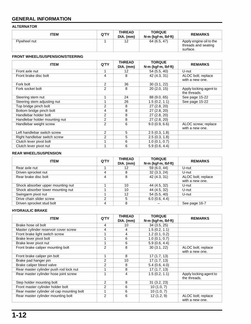
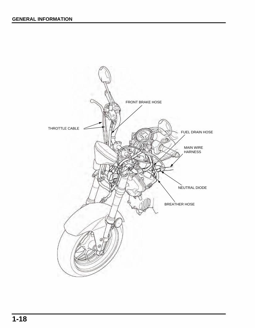
CABLE & HARNESS ROUTING
FRONT BRAKE HOSE
THROTTLE CABLE
CLUTCH CABLE COMBINATION METER CONNECTOR
HANDLEBARHANDLEBARHANDLEBAR
LEFT HANDLEBAR SWITCH WIRE
RIGHT HANDLEBAR SWITCH WIRE
Front Front
UpUp
TURN SIGNAL RELAY CONNECTOR
RIGHT TURN SIGNAL LIGHT WIRE CONNECTOR
LEFT TURN SIGNAL LIGHT WIRE CONNECTOR
HEADLIGHT BULB CONNECTOR
61K26000.book Page 15 Friday, July 12, 2013 3:51 PM

1-16
dummyheaddummyhead
GENERAL INFORMATION
LEFT HANDLEBAR SWITCH WIRE
HORN WIRE CONNECTOR
IGNITION SWITCH WIRE
RIGHT HANDLEBAR SWITCH WIRE
FRONT BRAKE HOSE
CLUTCH CABLE
FRONT BRAKE HOSE
RIGHT HANDLEBAR SWITCH WIRE
THROTTLE CABLE
HORN WIRE CONNECTOR
61K26000.book Page 16 Friday, July 12, 2013 3:51 PM

1-17
dummyheaddummyhead
GENERAL INFORMATION
O2 SENSOR WIRE
SPARK PLUG WIRESPARK PLUG WIRE
THROTTLE CABLE
FRONT BRAKE HOSE
RIGHT HANDLEBAR SWITCH WIRE
CLUTCH CABLE
0° – 10°
LEFT HANDLEBAR SWITCH WIRE
61K26000.book Page 17 Friday, July 12, 2013 3:51 PM
1-18
dummyheaddummyhead
GENERAL INFORMATION
MAIN WIRE HARNESS
FUEL DRAIN HOSE
BREATHER HOSE
NEUTRAL DIODE
THROTTLE CABLE
FRONT BRAKE HOSE
61K26000.book Page 18 Friday, July 12, 2013 3:51 PM

1-19
dummyheaddummyhead
GENERAL INFORMATION
CONNECTORS-VS SENSOR PULSE 1P -VS SENSOR 3P-NEUTRAL SWITCH 1P-ALTERNATOR 4P
FUEL FILTER
ALTERNATOR WIRE
NEUTRAL SWITCH WIRE
FUEL INJECTOR 2P CONNECTOR
ECM 33P CONNECTOR
VS SENSOR CONNECTOR
BANK ANGLE SENSOR 2P CONNECTOR
GROUND POINT
EOT SENSOR 2P CONNECTOR
SIDESTAND SWITCH WIRE
90°20°
90° - 110°
61K26000.book Page 19 Friday, July 12, 2013 3:51 PM

1-20
dummyheaddummyhead
GENERAL INFORMATION
IAT SENSOR CONNECTOR
CRANKCASE BREATHER HOSE (To Air cleaner housing)
FUEL PUMP 5P CONNECTOR
REGULATOR RECTIFIER 6P CONNECTOR
O2 SENSOR 1P CONNECTOR
BATTERY NEGATIVE (-) CABLE
SEAT LOCK CABLE
DLC
LICENSE/ REAR TURN SIGNAL LIGHT 4P CONNECTOR
BATTERY POSITIVE (+) CABLE
WIRE HARNESS (To fuse)
61K26000.book Page 20 Friday, July 12, 2013 3:51 PM

1-21
dummyheaddummyhead
GENERAL INFORMATION
TAIL LIGHT 3P CONNECTOR
LICENSE/ REAR TURN SIGNAL LIGHT 4P CONNECTOR
FUEL HOSE
CLUTCH CABLE
DLC
CRANKCASE BREATHER HOSE (To Air cleaner housing)
REAR BRAKE HOSE
REAR BRAKE LIGHT SWITCH
REAR MASTER CYLINDER
REAR MASTER CYLINDER RESERVOIR
61K26000.book Page 21 Friday, July 12, 2013 3:51 PM

1-22
dummyheaddummyhead
GENERAL INFORMATION
8 -10 mm
20°
REAR
CANISTER-to-EVAP PURGE CONTROL SOLENOID VALVE HOSE
FUEL TANK CHARGE HOSE
EVAP CANISTER DRAIN HOSE
PURGE CONTROL SOLENOID VALVE
PURGE HOSE
AIR INLET HOSE
40 mm
61K26000.book Page 22 Friday, July 12, 2013 3:51 PM

1-23
dummyheaddummyhead
GENERAL INFORMATION
TECHNICAL FEATURESPGM-FI SYSTEM WITHOUT MAP SENSOR AND IACVSYSTEM COMPONENTS
The PGM-FI system of this model consists of the following components:
– Injector [1]– Fuel pump unit [2]– ECM [3]– CKP sensor [4]– TP sensor [5]– EOT sensor [6]– IAT sensor [7]– O2 sensor [8]– Throttle body [9]– Idle air screw [10]
For PGM-FI system diagram (page 4-4).
[5]
[2]
[3]
[4]
[1]
[6]
[10]
[9]
[8]
[7]
61K26000.book Page 23 Friday, July 12, 2013 3:51 PM

1-24
dummyheaddummyhead
GENERAL INFORMATION
SYSTEM OUTLINE
This model's PGM-FI system eliminates the need of a MAP (Manifold Absolute Pressure) sensor and IACV (Idle Air Control Valve).
The system uses feedback from the O2 (Oxygen) and CKP (Crankshaft Position) sensors to compensate for the functions usuallycompleted by the MAP sensor.
The basic fuel discharge duration maps, which are programmed into the ECM, are constantly revised based on the O2 sensorfeedback.
As crankshaft speed slows slightly during the compression stroke, the CKP sensor signal allows the ECM to determine the exacttiming of the combustion process. This information would normally be provided by the MAP sensor.
IDLE AIR SCREW
The idle air screw [1] is located on the throttle body [2]. The idle air passage [3] provides equired air flow during idle speedoperation.The idle air passage is designed in a crank shape, which is not easily affected by deposits generated by reverse flow from thecombustion chamber. The volume of air flow can be adjusted by turning the idle air screw to increase/decrease the gap betweenthe screw and idle air passage wall in the throttle body.
TP SENSOR
CKP SENSOR
EOT SENSOR
O2 SENSOR
Basic fuel discharge duration Map selection
Fuel discharge duration management
Rich or Lean?
O2 feedback coefficients revision in each driving condition
INJECTOR
ECM
Constant revision
Throttle Map selection
IAT SENSOR
[1]
[3]
[1]
Adjustable area
[2]
[3]
61K26000.book Page 24 Friday, July 12, 2013 3:51 PM

1-25
dummyheaddummyhead
GENERAL INFORMATION
EMISSION CONTROL SYSTEMSSOURCE OF EMISSIONSThe combustion process produces carbon monoxide (CO), oxides of nitrogen (NOx) and hydrocarbons (HC). Control of carbonmonoxide, oxides of nitrogen and hydrocarbons is very important because, under certain conditions, they react to formphotochemical smog when subject to sunlight. Carbon monoxide does not react in the same way, but it is toxic.
CRANKCASE EMISSION CONTROL SYSTEMThe engine is equipped with a closed crankcase system to prevent discharging crankcase emissions into the atmosphere. Blow-bygas is returned to the combustion chamber through the crankcase breather hose [1], air cleaner [2] and throttle body [3].
THREE-WAY CATALYTIC CONVERTER This motorcycle is equipped with a three-way catalytic converter.
The three-way catalytic converter is in the exhaust system. Through chemical reactions, they convert HC, CO and NOx in theengine’s exhaust to carbon dioxide (CO2), nitrogen (N2) and water vapor.
No adjustment to these systems should be made although periodic inspection of the components is recommended.
NOISE EMISSION CONTROL SYSTEMTAMPERING WITH THE NOISE CONTROL SYSTEM IS PROHIBITED: Local law may prohibit the following acts or the causingthereof: (1) The removal or rendering inoperative by any person, other than for purposes of maintenance, repair or replacement, ofany device or element of design incorporated into any vehicle for the purpose of noise control prior to its sale or delivery to theultimate customer or while it is in use; (2) the use of the vehicle after such device or element of design has been removed orrendered inoperative by any person.
AMONG THOSE ACTS PRESUMED TO CONSTITUTE TAMPERING ARE THE ACTS LISTED BELOW:
1. Removal of, or puncturing of the muffler, baffles, header pipes or any other component which conducts exhaust gases.2. Removal of, or puncturing of any part of the intake system.3. Lack of proper maintenance.4. Removing or disabling any emissions compliance component, or replacing any compliance component with a non-compliant
component.
[3]
[1]
BLOW-BY GAS
FRESH AIR
[2]
61K26000.book Page 25 Friday, July 12, 2013 3:51 PM

MEMO
dummyheaddummyhead
61K26000.book Page 26 Friday, July 12, 2013 3:51 PM

10-1
10
dummytext
10. CYLINDER/PISTON
SERVICE INFORMATION···························10-2
TROUBLESHOOTING·································10-2
CYLINDER/PISTON ···································· 10-3
61K26000.book Page 1 Friday, July 12, 2013 3:51 PM

10-2
dummyheaddummyhead
CYLINDER/PISTON
CYLINDER/PISTON
SERVICE INFORMATIONGENERAL • This section covers service of the cylinder and piston. These services can be performed with the engine installed in the frame. • Take care not to damage the cylinder wall and piston. • Be careful not to damage the mating surfaces when removing the cylinder. Do not tap the cylinder too hard during removal. • When disassembling, mark and store the disassembled parts to ensure that they are reinstalled in their original locations. • Clean all disassembled parts with cleaning solvent and dry them by blowing them off with compressed air before inspection.
SPECIFICATIONSUnit: mm (in)
TORQUE VALUES
CYLINDER/PISTON
TROUBLESHOOTINGCompression too low, hard starting or poor performance at low speed • Leaking cylinder head gasket • Worn, stuck or broken piston ring • Worn or damaged cylinder and piston • Bent connecting rod
Compression too high, overheating or knocking • Excessive carbon built-up on piston head or combustion chamber
Excessive smoke • Worn cylinder, piston or piston rings • Improper installation of piston rings • Scored or scratched piston or cylinder wall • Cylinder head/valve problem (page 10-7)
Abnormal noise • Worn piston pin or piston pin hole • Worn cylinder, piston or piston rings • Worn connecting rod small end
ITEM STANDARD SERVICE LIMITCylinder I.D. 52.405 – 52.415 (2.0632 - 2.0636) 52.445 (2.0648)
Out-of-round – 0.10 (0.004)Taper – 0.10 (0.004)Warpage – 0.05 (0.002)
Piston, piston rings, piston pin
Piston O.D. 52.380 – 52.395 (2.0622 - 2.0628) 52.310 (2.0594)Piston O.D. measurement point 10 mm from bottom of skirt –Piston pin bore I.D. 13.002 – 13.008 (0.5119 - 0.5121) 13.03 (0.5130)Piston pin O.D. 12.994 – 13.000 (0.5116 - 0.5118) 12.98 (0.5110)Piston-to-piston pin clearance 0.002 – 0.014 (0.0001 - 0.0005) 0.05 (0.002)Piston ring-to-ring groove clearance (RIKEN)
Top 0.030 – 0.065 (0.0012 - 0.0026) 0.100 (0.0039)
Second 0.015 – 0.050 (0.0006 - 0.0020) 0.090 (0.0035)
Piston ring-to-ring groove clearance (TEIKOKU)
Top 0.015 – 0.050 (0.0006 - 0.0020) 0.090 (0.0035)
Second 0.015 – 0.050 (0.0006 - 0.0020) 0.090 (0.0035)
Piston ring end gap (RIKEN)
Top 0.10 – 0.25 (0.004 - 0.010) 0.50 (0.020)Second 0.10 – 0.30 (0.004 - 0.012) 0.60 (0.024)Oil (side rail) 0.20 – 0.70 (0.008 - 0.028) 1.10 (0.043)
Piston ring end gap (TEIKOKU)
Top 0.10 – 0.25 (0.004 - 0.010) 0.50 (0.020)Second 0.35 – 0.50 (0.014 - 0.020) 0.75 (0.030)Oil (side rail) 0.10 – 0.35 (0.004 - 0.014) 1.10 (0.043)
Cylinder-to-piston clearance 0.010 – 0.035 (0.0004 - 0.0014) 0.10 (0.004)Connecting rod small end I.D. 13.010 – 13.028 (0.5122 - 0.5129) 13.05 (0.514)Connecting rod-to-piston pin clearance 0.010 – 0.034 (0.0004 - 0.0013) 0.07 (0.003)
ITEM Q'TYTHREAD TORQUE
REMARKSDIA. (mm) N·m (kgf·m, lbf·ft)
Cam chain guide roller pin bolt 1 8 10 (1.0, 7)Cylinder stud bolt 4 8 – See page 10-7
61K26000.book Page 2 Friday, July 12, 2013 3:51 PM

10-3
dummyheaddummyhead
CYLINDER/PISTON
CYLINDER/PISTON
TOP RING
SECOND RING
SPACER
120°
120°120°
SECOND RING MARKING*
20 mm OR MORE
SIDE RAILS
TOP RING MARKING*
10 N·m (1.0 kgf·m, 7 lbf·ft)
Do not align the piston pin clip end gap with the piston cutout.
*Markings facing up
Apply engine oil:
- Cylinder bore
- Piston outer sliding area and piston ring grooves
- Piston pin hole inner surface
- Piston pin outer surface
- Piston ring whole surface
- Connecting rod small end inner surface
- Connecting rod big end
TOP RING MARKINGS:
RIKEN: R
TEIKOKU: N/T,T
SECOND RING MARKINGS:
RIKEN: RS
TEIKOKU: T2, A2
[5]
"IN" mark facing the intake sidePISTON PIN CLIP
[6]
[2] [1][3]
[4]
61K26000.book Page 3 Friday, July 12, 2013 3:51 PM

10-4
dummyheaddummyhead
CYLINDER/PISTON
REMOVAL
• Cylinder and piston can be serviced with the engineinstalled on the frame.
• Perform the ECM initializing procedure (page 4-24) ifthe cylinder is replaced or is overhauled.
Remove the cylinder head (page 9-9).
Disconnect the EOT sensor 2P connector (page 4-27).
Remove the cam chain guide roller pin bolt [1], sealingwasher [2] and guide roller [3]
Remove the cylinder.
Remove the gasket [1] and dowel pins [2].
Remove the piston pin clip [1] with pliers.
Push the piston pin [2] out of the piston [3] andconnecting rod, and remove the piston.
Be careful not todrop the guide rollerinto the crankcase.
[1]/[2]
[3]
[1]
[2]
Place a clean shoptowel over the
crankcase toprevent the clip from
falling into thecrankcase.
[1][3]
[2]
61K26000.book Page 4 Friday, July 12, 2013 3:51 PM

10-5
dummyheaddummyhead
CYLINDER/PISTON
INSTALLATIONInstall the dowel pins [1] and a new gasket [2].
Apply oil to the cylinder bore, piston sliding area, pistonring grooves and piston rings whole surface.
Route the cam chain [1] through the cylinder [2].
Install the cylinder over the piston while compressingthe piston rings with your fingers.
Be careful not todrop the guide rollerinto the crankcase.
Install the cam chain guide roller [1], new sealingwasher [2] and cam chain guide roller pin bolt [3].Tighten the roller pin bolt to the specified torque.
Connect the EOT sensor 2P connector (page 4-27).
Install the cylinder head (page 9-10).
• Perform the ECM initializing procedure (page 4-24)if the cylinder is replaced or is overhauled.
[2]
[1]
Be careful not todamage the pistonrings and cylinder
bore.
[1]
[2]
TORQUE:10 N·m (1.0 kgf·m, 7 lbf·ft)
[3][1]
[2]
61K26000.book Page 5 Friday, July 12, 2013 3:51 PM

10-6
dummyheaddummyhead
CYLINDER/PISTON
Clean the piston heads, ring grooves and skirts.Carefully install the piston rings onto the piston withtheir markings facing up.
• Be careful not to damage the piston and piston ringsduring installation.
• Do not confuse the top and second rings. • When installing the oil ring, install the spacer first
and then the side rails.
Stagger the piston ring end gaps 120 degrees apartfrom each other as shown.Stagger the side rails gaps as shown.
After installation, the piston rings should be free torotate in the groove.
Place a clean shop towel over the crankcase to preventthe dirt, dust or piston pin clips from entering thecrankcase.
Clean the gasket mating surfaces of the crankcase andcylinder thoroughly.
Apply oil to the connecting rod small end inner surface.
Apply oil to the piston [1] pin hole inner surface andpiston pin [2] outer surface.Install the piston with the "IN" mark [3] facing the intakeside.Instal the piston pin.
TOP RING MARKINGS:RIKEN: RTEIKOKU: N/T,T
SECOND RING MARKINGS:RIKEN: RSTEIKOKU: A2, T2
Do not align thegaps of the oil ring
side rails.
TOP RING
SECOND RING
SPACER
120°
120°120°
SECOND RING MARKING
20 mm (0.8 in) OR MORE
SIDE RAILS
TOP RING MARKING
Be careful not todamage the gasket
mating surfaces.
[1]
[3] [2]
61K26000.book Page 6 Friday, July 12, 2013 3:51 PM

10-7
dummyheaddummyhead
CYLINDER/PISTON
Install the new piston pin clip [1].
• Make sure the piston pin clips are seated securely. • Do not align the piston pin clip end gap with the
piston cutout. • Perform the ECM initializing procedure (page 4-24)
if the piston is replaced or is overhauled.
CYLINDER STUD BOLT REPLACEMENTIf replacing the cylinder stud bolts, be sure to installthem as shown.
Thread two nuts onto the stud bolt, and tighten themtogether, then use a wrench on them to turn the studbolt out.
Install and tighten new stud bolts to the specifiedtorque.
After tightening the stud bolts, check that the lengthfrom the bolt head to the crankcase surface is withinspecification.
INSPECTIONInspect the following parts for scratch, damage,abnormal wear, deformation, burning or clogs in oilpassages.
– Cylinder– Piston– Piston rings– Piston pin– Connecting rod small end
Measure each part and calculate the clearanceaccording to CYLINDER/PISTON SPECIFICATIONS(page 1-7).Replace any part if it is out of service limit.
[1]
TORQUE:11 N·m (1.1 kgf·m, 8 lbf·ft)175.0 ± 1.0 mm(6.89 ± 0.03 in)
61K26000.book Page 7 Friday, July 12, 2013 3:51 PM

MEMO
dummyheaddummyhead
61K26000.book Page 8 Friday, July 12, 2013 3:51 PM

11-1
11
dummytext
11. CLUTCH/GEARSHIFT LINKAGE
SERVICE INFORMATION···························11-2
TROUBLESHOOTING·································11-4
COMPONENT LOCATION··························11-5
RIGHT CRANKCASE COVER···················· 11-6
CLUTCH ······················································ 11-7
GEARSHIFT LINKAGE····························· 11-10
61K26000.book Page 1 Friday, July 12, 2013 3:51 PM

11-2
dummyheaddummyhead
CLUTCH/GEARSHIFT LINKAGECLUTCH/GEARSHIFT LINKAGE
SERVICE INFORMATIONGENERAL • This section covers service of the clutch and gearshift linkage. These service can be done with the engine installed in the frame. • Engine oil viscosity, oil level and the use of oil additives have an effect on clutch operation. Oil additives of any kind are
specifically not recommended. When the clutch does not disengage or the motorcycle creeps with clutch disengaged, inspectthe engine oil and oil level before servicing the clutch system.
SPECIFICATIONSUnit: mm (in)
TORQUE VALUESCLUTCH/GEARSHIFT LINKAGE
ITEM STANDARD SERVICE LIMITManual clutch Disc thickness 2.50 – 2.70 (0.099 - 0.106) 2.2 (0.09)
Plate warpage – 0.20 (0.008)Clutch spring free length 27.4 (1.08) -Clutch outer I.D. 23.000 – 23.013 (0.9055 - 0.9060) 23.06 (0.908)Clutch outer guide I.D. 16.991 – 17.009 (0.6689 - 0.6696) 17.049 (0.6712)
O.D. 22.959 – 22.980 (0.9039 - 0.9047) 22.940 (0.9031)Mainshaft O.D. at clutch outer guide 16.966 – 16.984 (0.6680 - 0.6687) 16.87 (0.66)
ITEM Q'TYTHREAD TORQUE
REMARKSDIA. (mm) N·m (kgf·m, lbf·ft)
Clutch center lock nut 1 14 64 (6.5, 47) Apply engine oil to the threads and seating surface.
Clutch lifter plate bolt 3 6 12 (1.2, 9)Gearshift cam plate socket bolt 1 6 10 (1.0, 7) Apply locking agent to
the threads.Gearshift return spring pin 1 8 30 (3.1, 22)Oil filter rotor lock nut 1 14 64 (6.5, 47) Apply engine oil to the
threads and seating surface.
Right crankcase cover protector bolt 3 6 12 (1.2, 9)Shift drum stopper arm bolt 1 6 12 (1.2, 9) Apply locking agent to
the threads.
61K26000.book Page 2 Friday, July 12, 2013 3:51 PM

11-3
dummyheaddummyhead
CLUTCH/GEARSHIFT LINKAGE
TOOLS
Locknut Wrench 5.5 x 2.5/30 mm07716-0020100
Extension Bar/Handle07716-0020500
Gear Holder M2.5 mm07724-0010100
07724-001A100 (U.S.A. only)
Holder Fly Wheel07725-0040001
Remover Weight07741-0010201
07936-371020A or 07936-3710200
Pilot 12 mm07746-0040200
Driver07749-0010000
Locknut Wrench 5.5 x 30 mm07916-6390001
Bearing Remover Shaft Set, 12 mm07936-1660101
07936-166010A (U.S.A. only)
Remover Head, 12 mm07936-1660110
Not available in U.S.A.
Remover Shaft, 12 mm07936-1660120
Not available in U.S.A.
Attachment, 28 x 3007946-1870100
61K26000.book Page 3 Friday, July 12, 2013 3:51 PM
11-4
dummyheaddummyhead
CLUTCH/GEARSHIFT LINKAGE
TROUBLESHOOTINGFaulty clutch operation can usually be corrected by adjusting the clutch system.
Clutch slips when accelerating • Incorrect clutch adjustment • Worn clutch disc • Weak clutch spring • Faulty clutch weight • Molybdenum or graphite additive
Motorcycle creeps • Faulty clutch weight • Faulty clutch weight spring • Incorrect idle air screw adjustment
Hard to shift • Damaged gearshift spindle • Damaged stopper plate and pin • Loose stopper plate bolt • Incorrect clutch adjustment • Loose gearshift cam plate bolt
Transmission jumps out of gear • Damaged stopper arm • Damaged gearshift cam plate • Loose gearshift cam plate bolt
Gearshift pedal will not return • Weak or broken gearshift spindle return spring • Bent gearshift spindle
Remover Handle07936-3710100
61K26000.book Page 4 Friday, July 12, 2013 3:51 PM

11-5
dummyheaddummyhead
CLUTCH/GEARSHIFT LINKAGE
COMPONENT LOCATION
64 N·m (6.5 kgf·m, 47 lbf·ft)
64 N·m (6.5 kgf·m, 47 lbf·ft)
12 N·m (1.2 kgf·m, 9 lbf·ft)
12 N·m (1.2 kgf·m, 9 lbf·ft)
10 N·m (1.0 kgf·m, 7 lbf·ft)
61K26000.book Page 5 Friday, July 12, 2013 3:51 PM

11-6
dummyheaddummyhead
CLUTCH/GEARSHIFT LINKAGE
RIGHT CRANKCASE COVERREMOVAL/INSTALLATION
• Clutch system can be serviced with the engineinstalled on the frame.
Drain the engine oil.
Remove the right step holder.
Loosen the bolts [1] in a crisscross pattern in severalsteps.
Remove the bolts, two clamps [2] and right crankcasecover.
Remove the dowel pins [1], orifice [2] and gasket [3].
Installation is in the reverse order of removal.
RIGHT CRANKCASE COVER PROTECTORRemove the three bolts [1] and right crankcase coverprotector.
Installation is in the reverse order of removal.
[1]
[2]
[1][1]
[2]
[3]
TORQUE:Right crankcase cover protector bolt12 N·m (1.2 kgf·m, 9 lbf·ft)
[1]
61K26000.book Page 6 Friday, July 12, 2013 3:51 PM

11-7
dummyheaddummyhead
CLUTCH/GEARSHIFT LINKAGE
CRANKSHAFT BEARING REPLACEMENTRemove the crankshaft bearing [1] using the specialtools as shown.
Install a new crankshaft bearing [1] with its sealed sidefacing down until it is fully seated using the specialtools.
CLUTCHREMOVAL/INSTALLATION
• Clutch system can be serviced with the engineinstalled on the frame.
Remove the following:
– Right crankcase cover (page 11-6)– Centrifugal oil filter (page 8-5)
Hold the primary drive and driven gear, then remove thecentrifugal filter rotor lock nut using the special tools.
Remove the washer and centrifugal filter rotor.
TOOLS:[2] Bearing remover set, 12mm 07936-1660101
Bearing remover shaft, 12 mm 07936-1660120Bearing remover head, 12mm 07936-1660110
[3] Remover weight 07741-0010201U.S.A. TOOLS:Bearing remover, 12 mm 07936-166010ARemover weight 07936-371020A or
07936-3710200Bearing handle 07936-3710100 [2]
[1][3]
TOOLS:[2] Driver 07749-0010000[3] Attachment, 28 x 30 mm 07946-1870100[4] Pilot, 12 mm 07746-0040200
[1][3]/[4]
[2]
TOOLS:[1] Lock nut wrench, 5.5 x 30 mm07916-6390001[2] Gear holder 2.5mm 07724-0010100 or
07724-001A100 (U.S.A. only)
[1] [2]
61K26000.book Page 7 Friday, July 12, 2013 3:51 PM

11-8
dummyheaddummyhead
CLUTCH/GEARSHIFT LINKAGE
Remove the clutch lifter bearing.
If the bearing cannot be removed by hand, use the toolslisted below and replace the bearing upon reinstallation.
Hold the primary drive and driven gear, then remove theclutch center lock nut [1] using the special tools thenremove the washer [2].
Remove the bolts [5] then remove the clutch assemblyand oil separator plate [6].
Remove the clutch outer guide [1] and collar [2] fromthe mainshaft.Remove the primary drive gear [3],woodruff key, andspacer from the crankshaft.
Installation is in the reverse order of removal.
• Apply engine oil to the each gear and collar. • Apply engine oil to the clutch center lock nut and
centrifugal filter rotor lock nut threads and seatingsurface then tighten it to the specified torque usingthe special tools.
MANUAL CLUTCH DISASSEMBLY/ASSEMBLYHold the clutch outer using the special tool and loosenthe bolts [1] in several steps.
Remove the bolts, clutch lifter plate [3] and clutchsprings [4].
TOOLS:Bearing remover, 10mm 07936-GEOA000Remover handle 07736-3710100Remover weight 07736-371020A
TOOLS:Gear holder 2.5mm 07724-0010100 or
07724-001A100 (U.S.A. only)
[3] Lock nut wrench, 20 x 24 mm 07716-0020100[4] Extension bar 07716-0020500 or
commercially available in U.S.A.
[1]/[2]
[5][6]
[3]/[4]
TORQUE:Clutch center lock nut 64 N·m (6.5 kgf·m,
47 lbf·ft)Centrifugal filter rotor lock nut
64 N·m (6.5 kgf·m, 47 lbf·ft)
[3]
[1]
[2]
TOOL:[2] Flywheel holder 07725-0040001
[2][1]/[4]
[3]
61K26000.book Page 8 Friday, July 12, 2013 3:51 PM

11-9
dummyheaddummyhead
CLUTCH/GEARSHIFT LINKAGE
Remove the clutch center assembly from the clutchouter.
Remove the following:
– Clutch center– Clutch discs– Clutch plates– Springs
INSPECTIONInspect the following parts for scratch, damage,abnormal wear and deformation. Replace if necessary.
– Clutch lifter bearing– Clutch springs– Clutch center– Clutch discs/plates– Clutch outer– Clutch outer guide– Mainshaft– Centrifugal filter rotor– Primary drive gear (page 13-7)
Measure each part according to CLUTCH/GEARSHIFTLINKAGE SPECIFICATIONS (page 1-8).Replace any part if it is out of service limit.
• Replace the clutch springs as a set. • Replace the clutch discs and plates as a set.
WASHER
LIFTER BEARING
BOLTLIFTER PLATE
CLUTCH SPRINGS
CLUTCH CENTER LOCK NUT
CLUTCH CENTER
COLLAR
CLUTCH OUTER
CLUTCH OUTER GUIDE
WASHER
PRESSURE PLATE
12 N·m (1.2 kgf·m, 9 lbf·ft)
CLUTCH PLATES
CLUTCH DISCS
61K26000.book Page 9 Friday, July 12, 2013 3:51 PM

11-10
dummyheaddummyhead
CLUTCH/GEARSHIFT LINKAGE
GEARSHIFT LINKAGEREMOVALRemove the following:
– Clutch (page 11-7)– Gearshift pedal (page 12-4)
Clean the gearshift spindle thoroughly to prevent thedirt or dust from entering the engine.
Remove the gearshift spindle [1] by holding down thegearshift arm [2] as shown.
Remove the gearshift cam plate bolt [3] and washer [4].
Lower and hold the stopper arm [1], then remove thegearshift cam plate [2].Remove the gearshift drum pins [3].Remove the bolt, stopper arm, washer [4] and returnspring [5].
INSPECTIONInspect the following parts for scratch, damage,abnormal wear and deformation. Replace if necessary.
– Gearshift spindle– Gearshift arm spring– Gearshift arm– Gearshift spindle oil seal
Measure each part according to CLUTCH/GEARSHIFTLINKAGE SPECIFICATIONS (page 1-8).Replace any part if it is out of service limit.
[2]
[1]
[3]/[4]
[2]
[1]
[3] [4]
[5]
61K26000.book Page 10 Friday, July 12, 2013 3:51 PM

11-11
dummyheaddummyhead
CLUTCH/GEARSHIFT LINKAGE
INSTALLATIONApply grease to the gearshift spindle oil seal [1] lips.
Apply locking agent to the threads of the shift drumstopper arm bolt [1].
Install the return spring [2], washer [3], stopper arm [4]and bolt.
Tighten the shift drum stopper arm bolt to the specifiedtorque.
Install the gearshift drum pins [1] into the holes on thegearshift drum.Hold the stopper arm [2] then install the gearshift camplate [3] by aligning the holes in the plate with thegearshift drum pins.
Apply locking agent to the threads of the gearshift camplate socket bolt [1].Install the washer [2] and bolt.Tighten the bolt to the specified torque.
Install the gearshift spindle [3] by aligning its returnspring ends with the shift return spring pin.
Install the following:
– Clutch (page 11-7)– Gearshift pedal
[1]
TORQUE:12 N·m (1.2 kgf·m, 9 lbf·ft)
[2]
[4]
[1]
[3]
[1] [3]
[2]
TORQUE:10 N·m (1.0 kgf·m, 7 lbf·ft)
Be careful not todamage the oil seal.
[2]
[1]
61K26000.book Page 11 Friday, July 12, 2013 3:51 PM

MEMO
dummyheaddummyhead
61K26000.book Page 12 Friday, July 12, 2013 3:51 PM

12-1
12
dummytext
12. ALTERNATOR/STARTER CLUTCH
SERVICE INFORMATION···························12-2
COMPONENT LOCATION··························12-3
LEFT CRANKCASE COVER ······················12-4
STATOR ······················································ 12-4
FLYWHEEL/STARTER CLUTCH ··············· 12-5
61K26000.book Page 1 Friday, July 12, 2013 3:51 PM

12-2
dummyheaddummyhead
ALTERNATOR/STARTER CLUTCHALTERNATOR/STARTER CLUTCH
SERVICE INFORMATIONGENERAL • These services can be done with the engine installed in the frame.
SPECIFICATIONSUnit: mm (in)
TORQUE VALUESALTERNATOR
TOOLS
ITEM STANDARD SERVICE LIMITStarter driven gear boss O.D. 45.660 – 45.673 (1.7976 - 1.7981) 45.642 (1.7969)
ITEM Q'TYTHREAD TORQUE
REMARKSDIA. (mm) N·m (kgf·m, lbf·ft)
Flywheel nut 1 12 64 (6.5, 47) Apply engine oil to the threads and seating surface.
Holder Fly Wheel07725-0040001
Inside Screw Puller 30 x 1.507KMC-HE00100
61K26000.book Page 2 Friday, July 12, 2013 3:51 PM

12-3
dummyheaddummyhead
ALTERNATOR/STARTER CLUTCH
COMPONENT LOCATION
64 N·m (6.5 kgf·m, 47 lbf·ft)
61K26000.book Page 3 Friday, July 12, 2013 3:51 PM

12-4
dummyheaddummyhead
ALTERNATOR/STARTER CLUTCH
LEFT CRANKCASE COVER • Alternator/starter clutch can be serviced with the
engine installed on the frame.
REMOVAL/INSTALLATIONDrain the engine oil (page 3-7).
Remove the following:
– Left shroud (page 2-4)– Gearshift pedal
Disconnect the alternator 4P connector.
Loosen the bolts [1] in a crisscross pattern in severalsteps.Remove the bolts and EOT sensor wire clamps [2].
Remove the left crankcase cover [3].
The left crankcase cover (stator) is magneticallyattached to the flywheel, be careful during removal.
Remove the gasket [1] and dowel pins [2].
Installation is in the reverse order of removal.
– Apply engine oil to the starter reduction gear journal[3].
– Install the gearshift pedal arm onto the gearshiftspindle, while aligning its slit with the punch mark.
STATORREMOVAL/INSTALLATIONRemove the left crankcase cover (page 12-4).
Remove the CKP sensor mounting bolts [1] and releasethe wire grommet [2] from the left crankcase cover.
[3]
[1]
[1]/[2]
[1]
[2]
[3]
[2]
[1]
61K26000.book Page 4 Friday, July 12, 2013 3:51 PM

12-5
dummyheaddummyhead
ALTERNATOR/STARTER CLUTCH
Remove the stator mounting bolts [1], then remove thestator [2] from the left crankcase cover.
Installation is in the reverse order of removal.
• Apply liquid sealant (THREE BOND 1215/1207B orequivalent) to the wire grommet seating surface andinstall the grommet into the cover groove.
FLYWHEEL/STARTER CLUTCHREMOVALRemove the left crankcase cover (page 12-4).
Remove the shaft [1], collar [2] and starter reductiongear [3].
Remove the flywheel nut [1] and washer [2] using thespecial tool.
Remove the flywheel/starter clutch [1] using the specialtool.
[1]
[2]
[1]
[3][2]
TOOL:[3] Flywheel holder 07725-0040001
[3]
[1]/[2]
TOOL:[2] Flywheel puller, 30 mm 07KMC-HE00100
[2]
[1]
61K26000.book Page 5 Friday, July 12, 2013 3:51 PM

12-6
dummyheaddummyhead
ALTERNATOR/STARTER CLUTCH
Remove the needle bearing [1].Remove the woodruff key [2].
INSTALLATIONInstall the woodruff key in the crankshaft key groove.
Apply engine oil to the starter clutch rolling surface ofthe crankshaft and needle bearing whole surface.Install the needle bearing to the crankshaft.
Wipe any oil off the mating surface of the crankshaftand flywheel.
Install the flywheel/starter clutch [1] to the crankshaft,aligning the key way with the woodruff key.
Install the washer [1].Apply engine oil to the flywheel nut [2] threads andseating surface, then install it.Hold the flywheel using the special tool and tighten theflywheel nut to the specified torque.
Apply engine oil to the starter reduction gear [1] journalarea and gear teeth.Install the starter reduction gear by aligning with thestarter drive gear [2] and starter driven gear [3].
During woodruff keyremoval/installation,
be careful not todamage the key
groove orcrankshaft.
[1]
[2]
[1]
Align
TOOL:[3] Flywheel holder 07725-0040001
TORQUE: 64 N·m (6.5 kgf·m, 47 lbf·ft)
[3]
[1]/[2]
[2]
[3]
[1]
61K26000.book Page 6 Friday, July 12, 2013 3:51 PM

12-7
dummyheaddummyhead
ALTERNATOR/STARTER CLUTCH
Apply engine oil to the starter reduction gear shaft [1]whole surface.Install the shaft and collar [2] into the reduction gear.
Install the left crankcase cover (page 12-4).
STARTER CLUTCH DISASSEMBLYCheck the operation of the one way clutch by turningthe driven gear.You should be able to turn the driven gear [1]counterclockwise smoothly, but the gear should not turnclockwise.
Remove the starter driven gear from the flywheel/starterclutch while turning the driven gear counterclockwise.
Hold the flywheel using the special tool and remove thestarter clutch outer mounting torx bolts [1].
Remove the starter clutch assembly [3].
Remove the starter clutch cover [1], rollers [2] andsprings [3] from the starter clutch outer [4].
[1]
[2]
[1]
TOOL:[2] Flywheel holder 07725-0040001
[2]
[1] [3]
[2]
[3][4]
[1]
61K26000.book Page 7 Friday, July 12, 2013 3:51 PM

12-8
dummyheaddummyhead
ALTERNATOR/STARTER CLUTCH
INSPECTIONInspect the following parts for scratch, damage,abnormal wear and deformation. Replace if necessary.
– Starter driven gear– Rollers, springs and starter clutch outer– Starter reduction gear and shaft– Starter driven gear needle bearing
Measure each part according to ALTERNATOR/STARTER CLUTCH SPECIFICATIONS (page 1-8).Replace any part if it is out of service limit.
STARTER CLUTCH ASSEMBLY
Install the springs [1] and rollers [2] into the starterclutch outer [3] as shown.
Install the starter clutch cover [4] while aligning its tabswith the holes in the starter clutch outer.
STARTER DRIVEN GEAR
FLYWHEEL
STARTER CLUTCH OUTER
TORX BOLT
STARTER CLUTCH COVER
ROLLER
SPRING
16 N·m (1.6 kgf·m, 12 lbf·ft)
[2]
[1][3]
[4]Align
61K26000.book Page 8 Friday, July 12, 2013 3:51 PM

12-9
dummyheaddummyhead
ALTERNATOR/STARTER CLUTCH
Install the starter clutch assembly [1] onto the flywheel[2].
Apply locking agent to the starter clutch outer mountingtorx bolt [1] threads as specified.Hold the flywheel using the special tool and tighten thebolts to the specified torque.
Apply engine oil to the starter clutch rolling surface ofthe driven gear [1].
Install the starter driven gear [1] to the flywheel/starterclutch while turning it counterclockwise.
Make sure that the starter driven gear turnscounterclockwise smoothly and does not turnclockwise.
Install the flywheel/starter clutch (page 12-6).
[1]
[2]
TOOL:[2] Flywheel holder 07725-0040001
TORQUE: 16 N·m (1.6 kgf·m, 12 lbf·ft)
[2]
[1]
Coating width: 6.5 ± 1.0 mm from tip
[1]
[1]
61K26000.book Page 9 Friday, July 12, 2013 3:51 PM

MEMO
dummyheaddummyhead
61K26000.book Page 10 Friday, July 12, 2013 3:51 PM

13-1
13
dummytext
13. CRANKCASE/TRANSMISSION/CRANKSHAFT
SERVICE INFORMATION···························13-2
TROUBLESHOOTING·································13-4
COMPONENT LOCATION··························13-5
CRANKCASE·············································· 13-6
CRANKSHAFT············································ 13-7
TRANSMISSION ······································· 13-10
61K26000.book Page 1 Friday, July 12, 2013 3:51 PM

13-2
dummyheaddummyhead
CRANKCASE/TRANSMISSION/CRANKSHAFT
CRANKCASE/TRANSMISSION/CRANKSHAFT
SERVICE INFORMATIONGENERAL • The crankcase must be separated to service the crankshaft, transmission. • The following parts must be removed before separating the crankcase.
– Engine (page 14-4)– Cylinder head (page 9-9)– Cam chain tensioner (page 9-15)– Flywheel (page 12-5)– Clutch/gearshift linkage (page 11-7)– Cylinder/piston (page 10-3)– Oil pump (page 8-4)– Starter motor (page 6-4)– Gear position switch (page 19-10)
• Be careful not to damage the crankcase mating surfaces when servicing. • Prior to assembling the crankcase halves, apply sealant to the mating surface. Wipe off excess sealant thoroughly.
SPECIFICATIONSUnit: mm (in)
ITEM STANDARD SERVICE LIMITCrankshaft Connecting rod side clearance 0.10 – 0.35 (0.004 - 0.0138) 0.60 (0.024)
Connecting rod radial clearance 0.004 – 0.016 (0.0002 - 0.0006) 0.05 (0.002)Runout – 0.10 (0.004)
Transmission Gear I.D. M2, M3 17.000 – 17.018 (0.6693 - 0.6700) 17.04 (0.671)C1 18.000 – 18.018 (0.7087 - 0.7094) 18.04 (0.710)C4 20.000 – 20.021 (0.7874 - 0.7882) 20.04 (0.789)
Bushing O.D. C1 17.966 – 17.984 (0.7073 - 0.7080) 17.94 (0.706)Bushing I.D. C1 15.000 – 15.018 (0.5906 - 0.5913) 15.04 (0.592)Gear-to-bushing clearance
C1 0.016 – 0.052 (0.0006 - 0.0020) 0.10 (0.004)
Mainshaft O.D. at M3 16.966 – 16.984 (0.6680 - 0.6687) 16.95 (0.667)Countershaft O.D. at C1
bushing 14.966 – 14.984 (0.5892 - 0.5899) 14.95 (0.589)
Gear-to-shaft clearance M3 0.016 – 0.052 (0.0006 - 0.0020) 0.09 (0.004)Bushing-to-shaft clearance C1 0.016 – 0.052 (0.0006 - 0.0020) 0.09 (0.004)
Shift fork/ Shift drum
Shift fork I.D. 10.000 – 10.018 (0.3937 - 0.3944) 10.07 (0.397)Shift fork claw thickness 4.93 – 5.00 (0.194 - 0.197) 4.90 (0.193)Shift fork shaft O.D. 9.986 – 9.995 (0.3931 - 0.3935) 9.93 (0.391)Shift drum journal I.D. Left 24.000 – 24.033 (0.9449 - 0.9462) 24.07 (0.948)
Right 28.000 – 28.021 (1.1024 - 1.1032) 28.08 (1.106)
61K26000.book Page 2 Friday, July 12, 2013 3:51 PM

13-3
dummyheaddummyhead
CRANKCASE/TRANSMISSION/CRANKSHAFT
TOOLS
Bearing Separator Set07631-0010000
Commercially available in U.S.A.
Remover Weight07741-0010201
07936-371020A or 07936-3710200 U.S.A. only
Attachment, 32 x 35 mm07746-0010100
Attachment, 37 x 40 mm07746-0010200
Attachment, 52 x 55 mm07746-0010400
Pilot 12 mm07746-0040200
Pilot 17 mm07746-0040400
Pilot 22 mm07746-0041000
Driver07749-0010000
Special Nut07931-HB3020A
Installer Shaft07931-ME4010B
Bearing Remover Shaft Set, 12 mm07936-1660101
07936-1660100A U.S.A. only
61K26000.book Page 3 Friday, July 12, 2013 3:51 PM

13-4
dummyheaddummyhead
CRANKCASE/TRANSMISSION/CRANKSHAFT
TROUBLESHOOTINGHard to shift • Incorrect clutch adjustment • Bent shift forks • Bent gearshift spindle • Damaged shift drum cam grooves • Incorrect engine oil viscosity
Transmission jumps out of gear • Worn gear dogs and dog holes • Broken shift drum stopper arm • Broken drum stopper arm spring • Broken gearshift spindle return spring • Worn or bent shift forks • Worn gear shifter groove
Excessive noise • Worn connecting rod big end bearing • Worn crankshaft bearing • Worn transmission bearing • Worn or damaged transmission gears
Remover Head, 12 mm07936-1660110
Not available in the U.S.A.
Remover Shaft, 12 mm07936-1660120
Not available in the U.S.A.
Remover Handle07936-3710100
Attachment, 28 x 3007946-1870100
Threaded adapter07AMF-K26A100
Shaft/Case Disassembly Set 1407JMF-KW70100
Collar 30.1 x 34 x 15 mm07YMF-KPB0100
61K26000.book Page 4 Friday, July 12, 2013 3:51 PM

13-5
dummyheaddummyhead
CRANKCASE/TRANSMISSION/CRANKSHAFT
COMPONENT LOCATION
61K26000.book Page 5 Friday, July 12, 2013 3:51 PM

13-6
dummyheaddummyhead
CRANKCASE/TRANSMISSION/CRANKSHAFT
CRANKCASESEPARATION/ASSEMBLYRefer to Service Information (page 13-2) for removal ofnecessary parts before separating the crankcase.
Remove the cam chain [1] from the timing sprocket.
Remove the bolt [1], holder plate [2], spring [3] andbearing push plug [4].
Loosen and remove the crankcase bolts [5] in acrisscross pattern in several steps.
Place the left crankcase [1] up.Carefully separate the left crankcase from the rightcrankcase [2] while tapping them at several locationswith a soft hammer.
Remove the dowel pins.
Clean off the sealant from the left and right crankcasemating surfaces.
[1]
[1]
[2]
[3]
[4]
[5]
[1]
[2]
61K26000.book Page 6 Friday, July 12, 2013 3:51 PM

13-7
dummyheaddummyhead
CRANKCASE/TRANSMISSION/CRANKSHAFT
CRANKCASE SEALANT
Clean off the sealant from the left and right crankcasemating surfaces.
Install the dowel pins to the right crankcase.
Apply light but thorough coating of sealant (THREEBOND 1215/1207B or equivalent) to the left crankcasemating surface except the oil passage area as shown.Mate the crankcase halves, install the bolts, and tightenthem in a crisscross pattern.
PRIMARY DRIVE GEAR SELECTIONThe primary drive gear has ID mark [1] on the gearsurface.
If the primary drive gear is replaced with a new one,select the same marked gear as the original gear.
If the crankcase replaced a new one, select the "B"marked gear.
CRANKSHAFTREMOVALRemove the transmission (page 13-10).
Remove the oil pump drive gear.
Remove the crankshaft [1] from the right crankcase [2]using a hydraulic press.
[1]
Be careful not todrop the crankshaft.
[2][1]
61K26000.book Page 7 Friday, July 12, 2013 3:51 PM

13-8
dummyheaddummyhead
CRANKCASE/TRANSMISSION/CRANKSHAFT
If the crankshaft bearing [1] remains on the crankshaft,remove it using a special tool as shown.
If the bearing [1] remains in the right crankcase, drive itout from the outside.
Discard the crankshaft bearing.
INSPECTIONInspect the following parts for scratch, damage,abnormal wear and deformation. Replace if necessary.
– Connecting rod– Timing sprocket
Measure each part according to CRANKCASE/CRANKSHAFT/TRANSMISSION BALANCERSPECIFICATIONS (page 1-8).Replace any part if it is out of service limit.
SIDE CLEARANCE
Measure the side clearance by inserting the feelergauge [1] between the crankshaft and connecting rodbig end.
TOOL:[2] Universal bearing puller 07631-0010000
or equivalent commercially available
U.S.A. TOOLS:Installer shaft 07931-ME4010BSpecial nut 07931-HB3010AThreaded adapter 07AMF-K26A100Assembly collar 07YMF-KPB0100
[1]
[2]
Do not reuse thecrankshaft bearing.
RIGHT CRANKCASE:
[1]
SERVICE LIMIT: 0.60 mm (0.024 in)
[1]
61K26000.book Page 8 Friday, July 12, 2013 3:51 PM

13-9
dummyheaddummyhead
CRANKCASE/TRANSMISSION/CRANKSHAFT
RADIAL CLEARANCE
Set the crankshaft on V-blocks and measure theconnecting rod big end radial clearance.
CRANKSHAFT
Place the crankshaft on a stand or V-blocks andmeasure the runout using a dial gauge.
The measuring locations are shown in the illustration.
Check the timing sprocket [1] for wear or damage.
Turn the outer race of the left crankshaft bearing [2]with your finger.The bearing should turn smoothly and quietly.Also check that the bearing inner race fits tightly on thecrankshaft.
Replace the crankshaft if the outer race does not turnsmoothly, quietly, or if inner race fits loosely on thecrankshaft.
CRANKSHAFT BEARING REPLACEMENTApply oil to a new right crankshaft bearing [1] rollingsurface.
Drive in the right crankshaft bearing with its markedside facing up until it is fully seated, using the specialtools.
For transmission bearing replacement (page 13-13).
SERVICE LIMIT: 0.05 mm (0.002 in)
SERVICE LIMIT: 0.10 mm (0.004 in)
46 mm
30 mm
120 mm
[1]
[2]
Be careful not todamage thecrankcase.
TOOLS:[2] Driver 07749-0010000[3] Attachment, 52 x 55 mm 07746-0010400[4] Pilot, 22 mm 07746-0041000
[2]
[1] [3]/[4]
61K26000.book Page 9 Friday, July 12, 2013 3:51 PM

13-10
dummyheaddummyhead
CRANKCASE/TRANSMISSION/CRANKSHAFT
INSTALLATIONApply 1 – 2 cm3 of oil to the connecting rod [1] big end.
Draw the crankshaft [2] into the right crankcase [3]bearing inner race using the special tool.
Install the transmission (page 13-10).
Assemble the crankcase (page 13-6).
TRANSMISSIONREMOVAL/INSTALLATIONSeparate the crankcase (page 13-6).
Remove the gearshift linkage (page 11-10)
Remove the shift fork shaft [1], shift forks [2] and shiftdrum [3].
Remove the mainshaft and countershaft as anassembly.
Remove the countershaft oil seal [1] from the leftcrankcase.
Be sure that theconnecting rod is
located in thecrankcase opening. TOOL:
[4] Assembly set, 14 mm 07JMF-KW70100U.S.A. TOOLS:
[2]
[3]
[1]
[4]
[2]
[3][1]
LEFT CRANKCASE:
[1]
61K26000.book Page 10 Friday, July 12, 2013 3:51 PM

13-11
dummyheaddummyhead
CRANKCASE/TRANSMISSION/CRANKSHAFT
INSPECTIONInspect the following parts for scratch, damage,abnormal wear and deformation. Replace if necessary.
– Transmission gears– Transmission bushings– Transmission bearings– Shift drum/journal– Shift forks– Shift fork shaft– Mainshaft– Countershaft– Gear shift spindle journal– Oil passages
Measure each part and calculate the clearanceaccording to CRANKCASE/CRANKSHAFT/TRANS-MISSION/BALANCER SPECIFICATIONS (page 1-8).Replace any part if it is out of service limit.
ASSEMBLYClean all parts in solvent and dry them thoroughly.
Apply molybdenum disulfide oil to the each rotatinggear inner surface and C1 bushing whole surface toensure initial lubrication.
Assemble all parts into their original positions.
• Check the gears for freedom of movement orrotation on the shaft.
• Install the washers and snap rings with thechamfered edges facing the thrust load side.
• Do not reuse a worn snap ring which could easilyspin in the groove.
• Check that the snap rings are seated in the groovesand align their end gaps with the grooves of thespline.
• Check the special washers are seated in the shaftgrooves.
61K26000.book Page 11 Friday, July 12, 2013 3:51 PM

13-12
dummyheaddummyhead
CRANKCASE/TRANSMISSION/CRANKSHAFT
MAINSHAFT:
COUNTERSHAFT:
SPECIAL WASHER
MAINSHAFT M1 GEAR (14T)
M2 GEAR (20T)
M3 GEAR (20T)
M4 GEAR (26T)
SPLINE WASHER
SPLINE WASHER
SNAP RING
: Gear teeth
: Rotating gear inner surface : Shift fork groove
C2 GEAR (31T)
C1 GEAR (35T)
COLLAR
SPECIAL WASHER
SNAP RING
THRUST WASHER
SPLINE WASHER
C4 GEAR (24T)
C1 BUSHING
C3 GEAR (23T)
SNAP RING
COUNTERSHAFT
: Gear teeth
: Rotating gear inner surface: Shift fork groove: C1 bushing whole surface
SPLINE WASHER
61K26000.book Page 12 Friday, July 12, 2013 3:51 PM

13-13
dummyheaddummyhead
CRANKCASE/TRANSMISSION/CRANKSHAFT
TRANSMISSION BEARING REPLACEMENTRemove the crankshaft (page 13-7).
Remove the bolts [1] and mainshaft bearing set plates[2].
Drive out the mainshaft bearing [3] and countershaftbearing [4] from the right crankcase.
Drive out the countershaft bearing [1] from the leftcrankcase.
Remove the mainshaft bearing [1] from the leftcrankcase using the special tools.
RIGHT CRANKCASE:
[4]
[3]
[1]/[2]
LEFT CRANKCASE:
[1]
TOOLS:[2] Bearing remover set, 12 mm 07936-1660101
Bearing remover shaft, 12 mm 07936-1660120Bearing remover head, 12 mm 07936-1660110
[3] Remover weight 07741-0010201U.S.A. TOOLS:Bearing remover, 12 mm 07936-1660100ARemover weight 07936-371020A or
07936-3710200Remover handle 07936-3710100
LEFT CRANKCASE:
[2]
[3]
[1]
61K26000.book Page 13 Friday, July 12, 2013 3:51 PM

13-14
dummyheaddummyhead
CRANKCASE/TRANSMISSION/CRANKSHAFT
Apply engine oil to the new bearing cavities.Drive new bearings into the crankcase with theirmarked side facing up until they are fully seated usingthe special tools.
Coating width6.5 ± 1.0 mm
(0.26 ± 0.04 in)from the tip.
Apply locking agent to the threads of the mainshaftbearing set plate bolt [1].
Install the mainshaft bearing set plates [2] and bolts tothe right crankcase and tighten the bolts securely.
Install the crankshaft (page 13-10).
TOOLS:[1] Left crankcase mainshaft bearing:
[2] Driver 07749-0010000[3] Attachment, 28 x 30 mm 07946-1870100[4] Pilot, 12 mm 07746-0040200
Left crankcase countershaft bearing:Driver 07749-0010000Attachment, 37 x 40 mm 07746-0010200Pilot, 17 mm 07746-0040400
Right crankcase mainshaft bearing:Driver 07749-0010000Attachment, 37 x 40 mm 07746-0010200Pilot, 17 mm 07746-0040400
Right crankcase countershaft bearing:Driver 07749-0010000Attachment, 32 x 35 mm 07746-0010100Pilot, 12 mm 07746-0040200
[2]
[3]/[4][1]
RIGHT CRANKCASE:
[2]
[1]
61K26000.book Page 14 Friday, July 12, 2013 3:51 PM

14-1
14
dummytext
14. ENGINE REMOVAL/INSTALLATION
SERVICE INFORMATION···························14-2
COMPONENT LOCATION··························14-3
ENGINE REMOVAL ···································· 14-4
61K26000.book Page 1 Friday, July 12, 2013 3:51 PM

14-2
dummyheaddummyhead
ENGINE REMOVAL/INSTALLATIONENGINE REMOVAL/INSTALLATION
SERVICE INFORMATIONGENERAL • During engine removal and installation, place the motorcycle a level surface. • Support the engine using a jack or other adjustable support to ease of engine hanger bolts removal. • The following components can be serviced with the engine installed in the frame.
– Alternator (page 12-5)– Manual clutch (page 11-7)– Gearshift linkage (page 11-10)– Cylinder head (page 9-9)– Cylinder/piston (page 10-3)– Oil pump (page 8-4)
• The following components require engine removal for service.– Crankshaft/transmission (page 13-6)– Shift forks/shift drum (page 13-10)
TORQUE VALUES
ENGINE REMOVAL/INSTALLATION
ITEM Q'TYTHREAD TORQUE
REMARKSDIA. (mm) N·m (kgf·m, lbf·ft)
Engine hanger nut (upper) 1 10 54 (5.5, 40)(lower) 1 10 54 (5.5, 40)(front) 1 10 54 (5.5, 40)
Drive sprocket fixing plate bolt 2 6 12 (1.2, 9)Step holder mounting bolt 2 8 31 (3.2, 23)
61K26000.book Page 2 Friday, July 12, 2013 3:51 PM

14-3
dummyheaddummyhead
ENGINE REMOVAL/INSTALLATION
COMPONENT LOCATION
54 N·m (5.5 kgf·m, 40 lbf·ft)
31 N·m (3.2 kgf·m, 23 lbf·ft)
54 N·m (5.5 kgf·m, 40 lbf·ft)
31 N·m (3.2 kgf·m, 23 lbf·ft)
12 N·m (1.2 kgf·m, 9 lbf·ft)
61K26000.book Page 3 Friday, July 12, 2013 3:51 PM

14-4
dummyheaddummyhead
ENGINE REMOVAL/INSTALLATION
ENGINE REMOVALSupport the motorcycle on its sidestand or with asuitable service stand.
Drain the engine oil (page 3-7).
Remove the following:
– Shroud (page 2-4)– Exhaust pipe (page 2-10)– Throttle drum cover (page 7-8)– Clutch cable receiver [1] and cable from the clutch
arm.– Starter motor cable [2]– Starter motor ground [3]
Disconnect the following:
– Spark plug cap [4]– O2 sensor shield, and connector [5] and release the
wire from the clamps– IAT sensor connector [6]
Loosen the lock nuts, drive chain adjusting nuts andaxle nut then, push the rear wheel forward.
Remove the following:
– Rear crankcase cover, disconnecting the wires fromthe wire clamp.
– Sprocket [1]– Breather hose [2]– Pull back the rubber boot of the gearshift shaft/
gearshift arm, remove the split pin, and disconnectthe shaft from the arm, then remove the gearshiftarm [3] from the gearshift spindle
– Intake pipe mounting bolts [4]
Disconnect the following and remove all wires from theirclamps:
– EOT sensor connector [5] and release the wire fromthe clamps
– Alternator connector [6]– VS sensor connector [7]– Neutral switch connector [8]
Remove the swingarm pivot nut [1], right step holdermounting bolt [2] and right step holder [3].
Install the swingarm pivot nut [1] to the swingarm pivotshaft temporality.
[1]
[2]
[4]
[3]
[5][6]
[5] [1]
[2][6]/[7]/[8]
[4]
[3]
[3]
[2]
[1][1]
61K26000.book Page 4 Friday, July 12, 2013 3:51 PM

14-5
dummyheaddummyhead
ENGINE REMOVAL/INSTALLATION
Remove the left step holder mounting bolt [1].
Pull the left step holder out by 200 mm, remove thecirclip and gearshift lever, and rotate the step holder toallow removal of the rear lower engine hanger nut.
Support the engine using a jack or other adjustablesupport.
Remove the front engine hanger nut [1], rear upperengine hanger nut [2] and rear lower engine hanger nut[3].
Remove the engine hanger bolts [4] and engine fromthe frame.
Installation is in the reverse order of removal.
Fill the recommended engine oil up to the proper level(page 3-7).Adjust the drive chain slack (page 3-9).
[1]
TORQUE:Rear upper engine hanger nut: 54 N·m (5.5 kgf·m,
40 lbf·ft)Rear lower engine hanger nut: 54 N·m (5.5 kgf·m,
40 lbf·ft)Front engine hanger nut: 54 N·m (5.5 kgf·m,
40 lbf·ft)Drive sprocket fixing plate bolt:12 N·m (1.2 kgf·m,
9 lbf·ft)Step holder mounting bolt: 31 N·m (3.2 kgf·m,
23 lbf·ft)Swingarm pivot nut: 54 N·m (5.5 kgf·m,
40 lbf·ft)
[1]/[4]
[2]/[4]
[3]/[4]
61K26000.book Page 5 Friday, July 12, 2013 3:51 PM

MEMO
dummyheaddummyhead
61K26000.book Page 6 Friday, July 12, 2013 3:51 PM

15-1
15
dummytext
15. FRONT WHEEL/SUSPENSION/STEERING
SERVICE INFORMATION···························15-2
TROUBLESHOOTING·································15-4
COMPONENT LOCATION··························15-5
FRONT WHEEL···········································15-6
FORK··························································· 15-8
HANDLEBAR ············································ 15-16
STEERING STEM ····································· 15-20
61K26000.book Page 1 Friday, July 12, 2013 3:51 PM

15-2
dummyheaddummyhead
FRONT WHEEL/SUSPENSION/STEERINGFRONT WHEEL/SUSPENSION/STEERING
SERVICE INFORMATIONGENERAL
• This section covers the front wheel, fork, handlebar and steering stem. • When servicing the front wheel, fork or steering stem, support the motorcycle using a jack or other support. • A contaminated brake disc or pad reduces stopping power. Discard contaminated pads and clean a contaminated disc with a
high quality brake degreasing agent. • After the front wheel installation, check the brake operation by applying the brake lever.
SPECIFICATIONSUnit: mm (in)
TORQUE VALUESFRONT WHEEL/SUSPENSION/STEERING
Frequent inhalation of brake pad dust, regardless of material composition could be hazardous to your health. • Avoid breathing dust particles. • Never use an air hose or brush to clean brake assemblies. Use an OSHA-approved vacuum cleaner.
ITEM STANDARD SERVICE LIMITMinimum tire tread depth – To indicatorCold tire pressure Driver only 200 kPa (2.00 kgf/cm2, 29 psi) –
Driver and passenger 200 kPa (2.00 kgf/cm2, 29 psi) –Axle runout – 0.2 (0.01)Wheel rim runout Radial – 2.0 (0.08)
Axial – 2.0 (0.08)Fork Pipe runout – 0.20 (0.010)
Recommended fork fluid Pro Honda Suspension Fluid SS-8 (10W) –Fluid level 75 (2.95) –Fluid capacity 221.0 ± 1.5 cm3 –
ITEM Q'TY THREAD TORQUE REMARKSDIA. (mm) N·m (kgf·m, lbf·ft)
Front axle nut 1 12 54 (5.5, 40) U-nutFront brake disc bolt 4 8 42 (4.3, 31) ALOC bolt; replace
with a new one.Fork bolt 2 36 30 (3.1, 22)Fork socket bolt 2 8 20 (2.0, 15) Apply locking agent to
the threads.Steering stem nut 1 24 88 (9.0, 65) See page 15-22Steering stem adjusting nut 1 26 1.5 (0.2, 1.1) See page 15-22Top bridge pinch bolt 2 8 27 (2.8, 20)Bottom bridge pinch bolt 4 8 27 (2.8, 20)Handlebar holder bolt 2 8 27 (2.8, 20)Handlebar holder mounting nut 2 8 27 (2.8, 20)Handlebar weight screw 2 6 9.0 (0.9, 6.6) ALOC screw; replace
with a new one.Left handlebar switch screw 2 5 2.5 (0.3, 1.8)Right handlebar switch screw 2 5 2.5 (0.3, 1.8)Clutch lever pivot bolt 1 6 1.0 (0.1, 0.7)Clutch lever pivot nut 1 6 5.9 (0.6, 4.4)
61K26000.book Page 2 Friday, July 12, 2013 3:51 PM

15-3
dummyheaddummyhead
FRONT WHEEL/SUSPENSION/STEERING
TOOLS
Fork Seal Driver 31mm070MD-K200100
or 070MD-K20A100 (U.S.A. only)
Attachment, 37 x 40 mm07746-0010200
Fork Seal Driver Attachment 27.2 mm07747-0010300
Pilot 12 mm07746-0040200
Bearing Remover Shaft 9 x 200L07746-0050100
Remover Head 12 mm07746-0050300
Driver07749-0010000
Locknut Wrench 5.7 x 5007916-3710101
Shaft Installer07WMF-GCM0100
or 07931-ME9010 (U.S.A. only)
Head Base07WMF-GCM0200
07WMF-GCMA200 (U.S.A. only)
Base07WMF-GCM0300
07WMF-GCMA300 (U.S.A. only)
Driver Attachment 48.5 mm07WMF-GCM0400
07WMF-GCMA400 (U.S.A. only)
61K26000.book Page 3 Friday, July 12, 2013 3:51 PM
15-4
dummyheaddummyhead
FRONT WHEEL/SUSPENSION/STEERING
TROUBLESHOOTINGHard steering • Insufficient tire pressure • Faulty tire • Steering stem lock nut too tight • Faulty steering head bearing • Faulty steering head bearing race • Bent steering stem
Steers to one side or does not track straight • Bent front axle • Wheel installed incorrectly • Worn or damaged front wheel bearings • Bent fork • Worn or damaged engine mounting bushings • Bent frame • Faulty steering head bearing
Front wheel wobbles • Loose front axle fasteners • Bent rim • Worn or damaged front wheel bearings
Front wheel turns hard • Front brake drag • Bent front axle • Faulty front wheel bearings
Soft suspension • Low tire pressure • Deteriorated fork fluid • Incorrect fork fluid weight • Insufficient fluid in fork • Weak fork spring
Hard suspension • High tire pressure • Too much fluid in fork • Incorrect fork fluid weight • Bent fork pipes • Clogged fork fluid passage
Suspension noisy • Bent fork slider • Insufficient fluid in fork • Loose fork fasteners
Remover 35mm07WMF-GCM0600
07WMF-GCMA600 (U.S.A. only)
61K26000.book Page 4 Friday, July 12, 2013 3:51 PM

15-5
dummyheaddummyhead
FRONT WHEEL/SUSPENSION/STEERING
COMPONENT LOCATION
54 N·m (5.5 kgf·m, 40 lbf·ft)
88 N·m (9.0 kgf·m, 65 lbf·ft)
27 N·m (2.8 kgf·m, 20 lbf·ft)
27 N·m (2.8 kgf·m, 20 lbf·ft)
30 N·m (3.1 kgf·m, 22 lbf·ft)
27 N·m (2.8 kgf·m, 20 lbf·ft)
27 N·m (2.8 kgf·m, 20 lbf·ft)
61K26000.book Page 5 Friday, July 12, 2013 3:51 PM

15-6
dummyheaddummyhead
FRONT WHEEL/SUSPENSION/STEERING
FRONT WHEEL
Support the motorcycle securely using a safety stand orhoist and raise the front wheel off the ground.
REMOVALLoosen the front axle nut [1].
Remove the front axle nut.
Remove the front axle out and remove the front wheel.
Remove the side collar from the wheel.
INSPECTIONInspect the following parts for damage, abnormal wear,deformation, looseness, smoothly operation or bend.
– Front axle– Wheel rim– Wheel bearing
Replace the bearings in pairs.
TIRE
Wheel balance directly affects stability, handling andoverall safety of the motorcycle. Always check balancewhen the tire has been removed from the rim.
Note the rotating direction mark [1] on the tire.
When installing the tires align the balance mark [2] ofthe tire and valve [3] of the rim within 50 mm.
Do not operate thebrake lever after
removing the frontwheel.
[1]
[2] [1]
[3]
61K26000.book Page 6 Friday, July 12, 2013 3:51 PM

15-7
dummyheaddummyhead
FRONT WHEEL/SUSPENSION/STEERING
DISASSEMBLY/ASSEMBLY
BEARING REPLACEMENT
Install the bearing remover head into the bearing.From the opposite side, install the bearing removershaft and drive the bearing out of the wheel hub.Remove the distance collar and drive out the otherbearing.
Pack all bearing cavities with grease.
Drive in a new left bearing [1] squarely with its sealedside facing up until it is fully seated.
Tighten the bolts in a criss-cross pattern in 2 or 3 steps.
Install the brake disc with its marked side facing up.
BRAKE DISC
WHEEL BEARING (6301U)
WHEEL BEARING (6301U)
DUST SEALDUST SEAL
DUST SEAL
DISTANCE COLLAR
54 N·m (5.5 kgf·m, 40 lbf·ft)
42 N·m (4.3 kgf·m, 31 lbf·ft)
TOOLS:Remover head, 12 mm [1] 07746-0050300Bearing remover shaft [2] 07746-0050100
[2]
[1]
TOOLS:Driver [2] 07749-0010000Attachment, 37 x 40 mm [3] 07746-0010200Pilot, 12 mm [4] 07746-0040200
[4]
[2]
[3]
[1]
61K26000.book Page 7 Friday, July 12, 2013 3:51 PM

15-8
dummyheaddummyhead
FRONT WHEEL/SUSPENSION/STEERING
WHEEL CENTER ADJUSTMENT
Apply thin coat of grease to the distance collar [1] andinstall it.
Drive in a new right bearing [2] squarely with its sealedside facing up until its inner race is seated on thedistance collar.
INSTALLATIONInstall the axle nut [1] and tighten it to the specifiedtorque.
FORKREMOVALRemove the following:
– Front fender (page 2-3)– Front wheel (page 15-6)
Remove the bolt [1] and front brake caliper from the leftfork leg.
Loosen the fork top bridge pinch bolt [1].
Loosen the fork bolt.
Loosen the bottom fork pinch bolt [2] and remove thefork leg from the steering stem.
TOOLS:Driver 07749-0010000Attachment, 37 x 40 mm 07746-0010200Pilot, 12 mm 07746-0040200
[2]
[1]
TORQUE:54 N·m (5.5 kgf·m, 40 lbf·ft)
[1]
Support the frontbrake caliper with apiece of wire so that
it does not hangfrom the front brake
hose.Do not twist the
brake hose.
[1]
In case of front forkdisassembly only:
[1]
[2]
61K26000.book Page 8 Friday, July 12, 2013 3:51 PM

15-9
dummyheaddummyhead
FRONT WHEEL/SUSPENSION/STEERING
DISASSEMBLYRemove the fork cap [1].
Install the special tool as shown.
To protect the dust seal from damage keep the specialtool in the shown position until outer tube [1] isremoved.
Completely loosen the fork bolt [1].
Pour out the fork fluid by pumping the fork pipe severaltimes.
Do not let the outer tube fall down as it can damage thedust seal.
Wrap the shop towel [1] around piston rod and hold itwith a pliers [2] as shown
Remove the bolt [3] and sealing washer [4].
[1]
TOOL:Oil seal driver, 31mm [2] 070MD-K200100 or
070MD-K20A100 (U.S.A. only)
[2]
[1]
[1]
[1]
[3]/[4]
[2]
61K26000.book Page 9 Friday, July 12, 2013 3:51 PM

15-10
dummyheaddummyhead
FRONT WHEEL/SUSPENSION/STEERING
Remove the fork bolt [1] and o-ring [2].
Remove the stopper rubber [1] and seat [2].
Remove the stopper ring [1].
Be careful not toscratch the damper
assembly slidingsurface.
Remove the dust seal [1] using the screw driver.
[2][1]
[1][2]
[1]
[1]
61K26000.book Page 10 Friday, July 12, 2013 3:51 PM
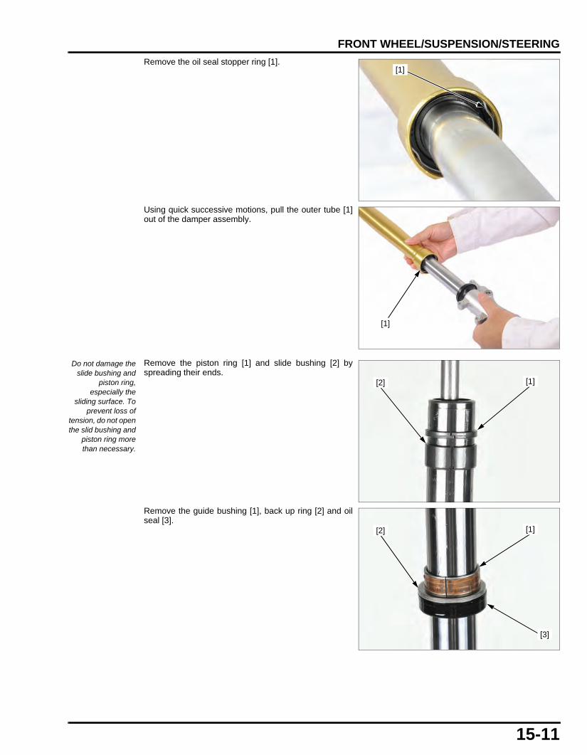
15-11
dummyheaddummyhead
FRONT WHEEL/SUSPENSION/STEERING
Remove the oil seal stopper ring [1].
Using quick successive motions, pull the outer tube [1]out of the damper assembly.
Remove the piston ring [1] and slide bushing [2] byspreading their ends.
Remove the guide bushing [1], back up ring [2] and oilseal [3].
[1]
[1]
Do not damage theslide bushing and
piston ring,especially the
sliding surface. Toprevent loss of
tension, do not openthe slid bushing and
piston ring morethan necessary.
[1][2]
[2] [1]
[3]
61K26000.book Page 11 Friday, July 12, 2013 3:51 PM

15-12
dummyheaddummyhead
FRONT WHEEL/SUSPENSION/STEERING
INSPECTIONInspect the following parts for damage, abnormal wear,bend, deformation and scoring.
– Fork pipe– Outer tube– Slide bushing– Guide bushing– Back up ring
ASSEMBLY
Before assembly, wash all parts with high flash point ornon-flammable solvent and wipe them dry.
Install the guide bushing [1], back up ring [2] and newoil seal [3].
DUST SEAL
OIL SEAL
GUIDE BUSHING
SLIDE BUSH
STOPPER RING
OUTER TUBE
FORK CAP
20 N·m (2.0 kgf·m, 15 lbf·ft)
SEALINGWASHER
FORK BOLT
STOPPER RUBBER
SEAT
PISTON RING
BACK UP RING
OIL SEAL STOPPER RING
DAMPER ASSEMBLY
BOLT
O-RING
30 N·m (3.1 kgf·m, 22 lbf·ft)
[2] [1]
[3]
61K26000.book Page 12 Friday, July 12, 2013 3:51 PM

15-13
dummyheaddummyhead
FRONT WHEEL/SUSPENSION/STEERING
Install the piston ring [1] and slide bushing [2] byspreading their ends.
Install the outer tube [1].
Drive the new oil seal [1] into the outer tube [2] by usingthe special tool.
Install the oil seal stopper ring [1].
[1][2]
[1]
TOOL:Oil seal driver, 31mm [3] 070MD-K200100 or
070MD-K20A100 (U.S.A. only)
[2]
[1]
[3]
[1]
61K26000.book Page 13 Friday, July 12, 2013 3:51 PM
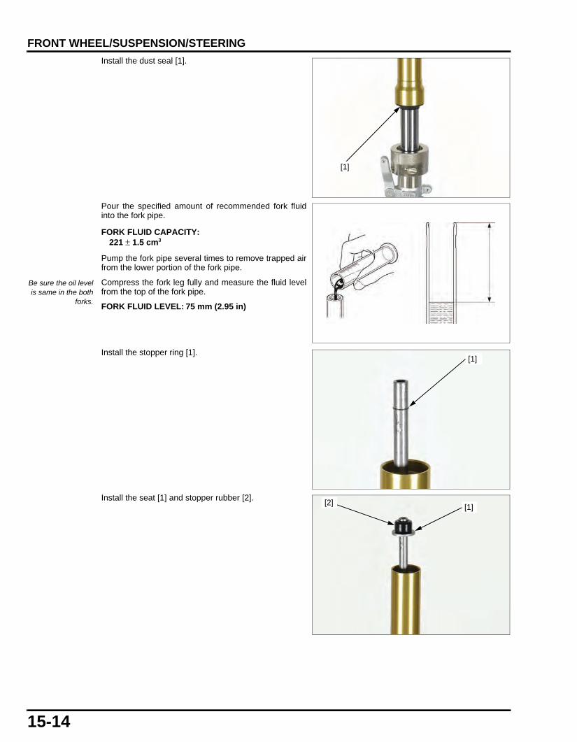
15-14
dummyheaddummyhead
FRONT WHEEL/SUSPENSION/STEERING
Install the dust seal [1].
Pour the specified amount of recommended fork fluidinto the fork pipe.
Pump the fork pipe several times to remove trapped airfrom the lower portion of the fork pipe.
Compress the fork leg fully and measure the fluid levelfrom the top of the fork pipe.
Install the stopper ring [1].
Install the seat [1] and stopper rubber [2].
[1]
FORK FLUID CAPACITY:221 ± 1.5 cm3
Be sure the oil levelis same in the both
forks.FORK FLUID LEVEL: 75 mm (2.95 in)
[1]
[2][1]
61K26000.book Page 14 Friday, July 12, 2013 3:51 PM

15-15
dummyheaddummyhead
FRONT WHEEL/SUSPENSION/STEERING
Install the fork bolt [1] and new o-ring [2].
Wrap the shop towel [1] around piston rod and hold itwith a pliers [2] as shown
Apply a locking agent to the fork socket bolt [3] threadsand install with a new sealing washer [4].
Tighten the fork socket bolt.
Tighten the fork bolt loosely and Install the fork cap [1].
INSTALLATIONInstall the fork leg into the bottom and top bridge.
Align the top of the outer tube with the upper surface ofthe top bridge.
Tighten the bottom bridge pinch bolts [1] to thespecified torque.
Tighten the top bridge pinch bolts [2] loosely.
[2]
[1]
TORQUE:20 N·m (2.0 kgf·m, 15 lbf·ft)
[1]
[3]
[2][4]
[1]
TORQUE:27 N·m (2.8 kgf·m, 20 lbf·ft)
[2]
[1]
61K26000.book Page 15 Friday, July 12, 2013 3:51 PM

15-16
dummyheaddummyhead
FRONT WHEEL/SUSPENSION/STEERING
Tighten the fork bolt [1] to the specified torque.
Tighten the top bridge pinch bolts [1] to the specifiedtorque.
Install the front brake caliper and new mounting bolts [1]to the left fork leg, then tighten them to the specifiedtorque.
Install the following:
– Front wheel (page 15-8)– Front fender (page 2-3)
HANDLEBARREMOVAL
The rearview mirrorlock nuts has left
hand threads.
Remove the rearview mirrors and wire bands.
Remove the screws [1] and left handlebar switch [2].
TORQUE: 30 N·m (3.1 kgf·m, 22 lbf·ft)
[1]
TORQUE:27 N·m (2.8 kgf·m, 20 lbf·ft)[1]
TORQUE:30 N·m (3.1 kgf·m, 22 lbf·ft)[1]
[1]
[2]
61K26000.book Page 16 Friday, July 12, 2013 3:51 PM

15-17
dummyheaddummyhead
FRONT WHEEL/SUSPENSION/STEERING
Slide the clutch switch cover off.
Disconnect the clutch switch connector.
Remove the bolts [1], holder and clutch lever bracket[2].
Disconnect the front brake switch connector [1].
Remove the bolts and front master cylinder holder [2].
Remove the four caps, four socket bolts [1], upperholders [2] and handlebar.
Remove the right handlebar switch and throttle pipe [1]from the handlebar.
Disconnect the throttle cable [2] from the throttle pipe.
[1]
[2]
[2]
[1]
[1]
[2]
[1]
[2]
61K26000.book Page 17 Friday, July 12, 2013 3:51 PM

15-18
dummyheaddummyhead
FRONT WHEEL/SUSPENSION/STEERING
INSTALLATIONIf the left handle grip [1] were removed, apply HondaBond A or equivalent to the inside of the grip and to theclean surfaces of the left handlebar [2].
Wait 3 – 5 minutes and install the grip.
Rotate the grip for even application of the adhesive.
Apply grease to the throttle cable ends [1] and cableguide grooves of the throttle pipe [2].
Connect the throttle cable ends to the throttle pipe.
Install the right handlebar switch and throttle pipe ontothe handlebar.
Install the handlebar onto the lower holders by aligningthe punch mark on the handlebar with the top edge ofthe lower holder.
Install the upper holders [1] with the punch marks facingforward.
Tighten the forward bolts first, then tighten the rear boltsto the specified torque.
Install the right handlebar switch [1] aligning its locatingpin with the hole on the handlebar.
Install the right handlebar switch screws [2].
Tighten the forward screw first, then the rear screw.
Allow the adhesiveto dry for 1 hour
before using.
[2]
[1]
[2]
[1]
Align the punchmark [2] on the
handlebar with themating surface of
the upper and lowerholders.
TORQUE:27 N·m (2.8 kgf·m, 20 lbf·ft)
[2]
[1]
[2]
[1]
61K26000.book Page 18 Friday, July 12, 2013 3:51 PM

15-19
dummyheaddummyhead
FRONT WHEEL/SUSPENSION/STEERING
Install the front master cylinder, holder ("UP" markfacing up) and bolts [1].
Align the end of the master cylinder with the punchmark on the handlebar and tighten the upper bolt first,then the lower bolt to the specified torque.
Align the end of the clutch lever bracket with the punchmark on the handlebar and tighten the upper bolt [2]first, then the lower bolt to the specified torque.
Connect the clutch switch connector.
Install the left handlebar switch [1] aligning its locatingpin with the hole on the handlebar.
Install the left handlebar switch screws [2].Tighten the forward screw first, then the rear screw.
Install the four caps, wire bands and mirrors.
TORQUE:10 N·m (1.0 kgf·m, 7 lbf·ft)
[1]
Align
TORQUE:10 N·m (1.0 kgf·m, 7 lbf·ft)Align
[2]
[1]
61K26000.book Page 19 Friday, July 12, 2013 3:51 PM

15-20
dummyheaddummyhead
FRONT WHEEL/SUSPENSION/STEERING
STEERING STEMREMOVALRemove the headlight assembly (page 2-7).
Disconnect the following:
– Right handlebar switch connector [1]– Left handlebar switch connector [2]– Combination meter connector [3]– Ignition switch connector [4]– Horn connector [5]
Remove the horn harness clip from the stay [6]
Remove the handlebar (page 15-16).
Remove the top bridge pinch bolt [1], steering stem nut[2], washer [3] and top bridge.
Remove the fork [1] (page 15-8).Remove the front brake hose clamp from the steeringstem.Remove the headlight/meter assembly bracket from thesteering stem.
Loosen the steering stem adjusting nut using a specialtool.
Hold the steering stem and remove the steering stemadjusting nut.
Remove the following:
– Upper inner race– Upper bearing– Steering stem– Lower bearing
[1]/[4]
[3]
[2]
[5]
[6]
[1]
[2]/[3]
TOOL:Steering stem socket [2] 07916-3710101
[1]
[2]
61K26000.book Page 20 Friday, July 12, 2013 3:51 PM

15-21
dummyheaddummyhead
FRONT WHEEL/SUSPENSION/STEERING
BEARING REPLACEMENTOUTER RACE
• Always replace the steel bearings and races as aset.
Replace the outer races using the special tools:
TOOL:
[1] Shaft installer 07WMF-GCM0100
[2] Head base 07WMF-GCM0200
[3] Base 07WMF-GCM0300
[4] Driver attachment 48.5 mm (2 pieces)
07WMF-GCM0400
[5] Remover 35 mm 07WMF-GCM0600
U.S.A. TOOLS:
Installer shaft 07WMF-KZ30200
Head base 07WMF-GCMA200
Base 07WMF-GCMA300
Driver attachment 48.5 mm 07WMF-GCMA400
Remover 35 mm 07WMF-GCMA600
UPPER OUTER RACE
Tighten
[3]
[2]
[1]
[5]
[4]
[3]
UPPER OUTER RACE INSTALLATION
UPPER OUTER RACE INSTALLATION
LOWER OUTER RACE REMOVAL
UPPER OUTER RACE REMOVAL
[1]
[5]
Tighten
LOWER OUTER RACE
[2]
[3]
[4]
[4]
UPPER OUTER RACE
LOWER OUTER RACE
LOWER OUTER RACE[1]
[4]
[4]
Tighten
[1]
Tighten
61K26000.book Page 21 Friday, July 12, 2013 3:51 PM

15-22
dummyheaddummyhead
FRONT WHEEL/SUSPENSION/STEERING
LOWER INNER RACE
Removal: Temporarily install the steering stem nut onto the stemto prevent the threads from being damaged whenremoving the lower inner race from the steering stem.
Remove the dust seal and washer.
Remove the lower bearing inner race with a chisel orequivalent tool being careful not to damage the stem.
Install the washer and new dust seal to the steeringstem.
Install a new lower bearing inner race [1] using thefollowing tool and hydraulic press.
INSTALLATION • Always replace the steel balls and races as a set.
Installation:
TOOL:Steering stem driver attachment 07946-KA6000A
[1][2]
TOP BRIDGE
CAP NUT
UPPER BEARING
LOWER BEARING
LOWER INNER RACE
WASHER
UPPER OUTER RACE
UPPER INNER RACE
TOP THREAD
STEERING STEM
grease with extreme pressure agent (recommended: EXCELITE EP2 manufactured by KYODO YUSHI, Japan or Shell ALVANIA EP2 or equivalent)
DUST SEAL
LOWER OUTER RACE
WASHER
HEADLIGHT BRACKET
HORN STAY
: BEARING
: BEARING RACE
: DUST SEAL
: BEARING
: INNER RACE
: OUTER RACE
: DUST SEAL
61K26000.book Page 22 Friday, July 12, 2013 3:51 PM

15-23
dummyheaddummyhead
FRONT WHEEL/SUSPENSION/STEERING
Install the top thread.Hold the steering stem and tighten the stem top thread[1] to the initial torque using the special tool.
Turn the steering stem lock-to-lock several times toseat the bearing.
Loosen the top thread [1].
Hold the steering stem and tighten the stem top thread[1] to the initial torque using the special tool.
Install the fork (page 15-15).
Install the top bridge, washer and tighten the stem nut[1] to the specified torque.
Make sure the steering stem moves smoothly withoutplay or binding.
Install the handlebar (page 15-16).
TOOL:Steering stem socket [2] 07916-3710101
TORQUE:27 N·m (2.8 kgf·m, 20 lbf·ft)
[2]
[1]
TOOL:Steering stem socket 07916-3710101
TORQUE:1.5 N·m (0.2 kgf·m, 1.1 lbf·ft)
[1]
TORQUE:88 N·m (9.0 kgf·m, 65 lbf·ft)
[1]
61K26000.book Page 23 Friday, July 12, 2013 3:51 PM

15-24
dummyheaddummyhead
FRONT WHEEL/SUSPENSION/STEERING
Connect the following:
– Right handlebar switch connector [1]– Left handlebar switch connector [2]– Combination meter connector [3]– Ignition switch connector [4]– Horn connector [5]– horn harness clip to the stay [6]– Horn
Install the headlight assembly (page 2-7).
[1]/[4]
[3]
[2]
[5]
[6]
61K26000.book Page 24 Friday, July 12, 2013 3:51 PM

16-1
16
dummytext
16. REAR WHEEL/SUSPENSION
SERVICE INFORMATION···························16-2
TROUBLESHOOTING·································16-3
COMPONENT LOCATION··························16-4
REAR WHEEL············································· 16-5
SHOCK ABSORBER ·································· 16-7
SWINGARM ················································ 16-8
61K26000.book Page 1 Friday, July 12, 2013 3:51 PM

16-2
dummyheaddummyhead
REAR WHEEL/SUSPENSIONREAR WHEEL/SUSPENSION
SERVICE INFORMATIONGENERAL • When servicing the rear wheel and suspension, support the motorcycle using a safety stand or hoist. • A contaminated brake disc or pad reduces stopping power. Discard contaminated pads and clean a contaminated disc with a
high quality brake degreasing agent. • After the rear wheel installation, check the brake operation by applying the brake pedal. • Use only tires marked "TUBELESS" and tubeless valves on rim marked "TUBELESS TIRE APPLICABLE". • Use genuine Honda replacement bolts and nuts for all suspension pivot and mounting point. • For brake system information (page 17-2).
SPECIFICATIONSUnit: mm (in)
TORQUE VALUESREAR WHEEL/SUSPENSION
TOOLS
ITEM STANDARD SERVICE LIMITMinimum tire tread depth – To indicatorCold tire pressure Driver only 200 kPa (2.00 kgf/cm2, 29 psi) –
Driver and passenger 200 kPa (2.00 kgf/cm2, 29 psi) –Axle runout – 0.2 (0.01)Wheel rim runout Radial – 2.0 (0.08)
Axial – 2.0 (0.08)Drive chain Size/link 420/106 –
Slack 30 – 40 (1.2 - 1.6) –
ITEM Q'TYTHREAD TORQUE
REMARKSDIA. (mm) N·m (kgf·m, lbf·ft)
Rear axle nut 1 12 59 (6.0, 44) U-nutDriven sprocket nut 4 8 32 (3.3, 24) U-nutRear brake disc bolt 4 8 42 (4.3, 31) ALOC bolt; replace
with a new one.Shock absorber upper mounting nut 1 10 44 (4.5, 32) U-nutShock absorber lower mounting nut 1 10 44 (4.5, 32) U-nutSwingarm pivot nut 1 12 54 (5.5, 40) U-nutDrive chain slider screw 2 5 6.0 (0.6, 4.4)Driven sprocket stud bolt 4 8 – See page 16-7
Attachment, 32 x 35 mm07746-0010100
Attachment, 37 x 40 mm07746-0010200
Pilot 12 mm07746-0040200
Pilot 17 mm07746-0040400
Bearing Remover Shaft 9 x 200L07746-0050100
Remover Head 12 mm07746-0050300
61K26000.book Page 2 Friday, July 12, 2013 3:51 PM

16-3
dummyheaddummyhead
REAR WHEEL/SUSPENSION
TROUBLESHOOTINGSteers to one side or does not track straight • Drive chain adjusters not adjusted equally • Bent axle • Bent frame • Worn swingarm pivot components
Rear wheel wobbling • Bent rim • Worn wheel bearing • Worn driven flange bearing • Faulty tire • Bent frame or swingarm • Axle not tightened properly • Unbalanced tire and wheel • Insufficient tire pressure
Wheel hard to turn • Brake drag • Faulty wheel bearing • Faulty driven flange bearing • Bent axle • Drive chain too tight
Soft suspension • Weak shock absorber spring • Oil leakage from damper unit • Insufficient tire pressure
Stiff suspension • Bent shock absorber damper rod • Damaged suspension or swingarm pivot bushing • Bent swingarm pivot or frame
Rear suspension noisy • Loose suspension fasteners • Faulty shock absorber
Driver07749-0010000
61K26000.book Page 3 Friday, July 12, 2013 3:51 PM
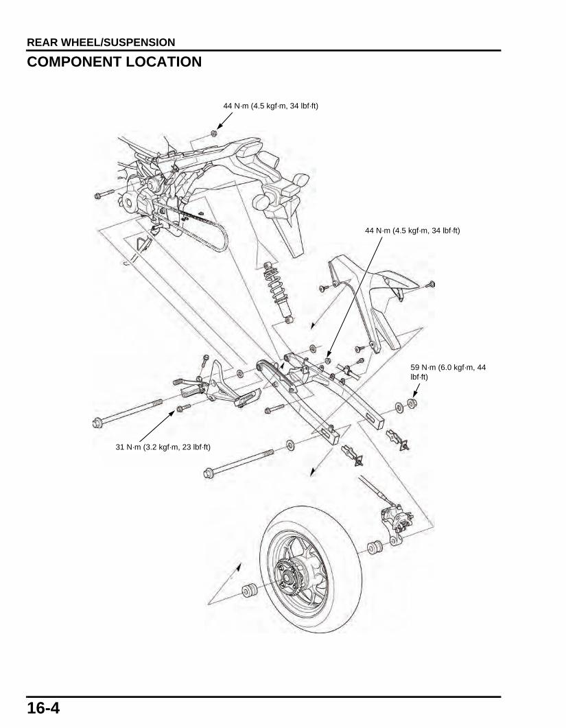
16-4
dummyheaddummyhead
REAR WHEEL/SUSPENSION
COMPONENT LOCATION
59 N·m (6.0 kgf·m, 44 lbf·ft)
44 N·m (4.5 kgf·m, 34 lbf·ft)
31 N·m (3.2 kgf·m, 23 lbf·ft)
44 N·m (4.5 kgf·m, 34 lbf·ft)
61K26000.book Page 4 Friday, July 12, 2013 3:51 PM

16-5
dummyheaddummyhead
REAR WHEEL/SUSPENSION
REAR WHEELREMOVALSupport the motorcycle using a safety stand or hoist,raise the rear wheel off the ground.
Loosen the rear axle nut [1], both lock nuts [2] andadjusting nut [3].
Push the rear wheel forward.Derail the drive chain from the driven sprocket.
Remove the axle nut, axle and rear wheel.
INSPECTIONInspect the following parts for damage, abnormal wear,deformation, looseness, smoothly operation or bend.
– Rear axle– Wheel rim– Tire– Wheel and driven flange bearings
Replace the bearings in pairs.
DISASSEMBLY/ASSEMBLY
[1][3]
[2]
BEARING (6203U)
DAMPER RUBBER
BEARING (6301U)
DUST SEAL
DUST SEAL
59 N·m (6.0 kgf·m, 44 lbf·ft)
32 N·m (3.3 kgf·m, 24 lbf·ft)
42 N·m (4.3 kgf·m, 31 lbf·ft)
O-RING
DISTANCE COLLAR
BEARING (6301U)
61K26000.book Page 5 Friday, July 12, 2013 3:51 PM

16-6
dummyheaddummyhead
REAR WHEEL/SUSPENSION
WHEEL BEARING REPLACEMENT
Install the bearing remover head into the bearing.From the opposite side, install the bearing removershaft and drive the bearing out of the wheel hub.Remove the distance collar and drive out the otherbearing.
Pack all bearing cavities with grease.
Drive in a new left bearing [1] squarely with its sealedside facing up until it is fully seated.
DRIVEN FLANGE
Remove the driven flange collar [1].
Drive out the driven flange bearing [2].
Never install the oldbearing, once thebearing has been
removed, thebearing must be
replaced with newones.
Drive in a new driven flange bearing squarely until it isfully seated.
TOOLS:Remover head, 12 mm [1] 07746-0050300Bearing remover shaft [2] 07746-0050100
[2]
[1]
Never install the oldbearings. Once the
bearings have beenremoved, the
bearings must bereplaced with new
ones.
TOOLS:Driver [2] 07749-0010000Attachment, 32 x 35 mm [3] 07746-0010100Pilot, 12 mm [4] 07746-0040200
[4]
[2]
[3]
[1]
[2]
[1]
TOOLS:Driver 07749-0010000Attachment, 37 x 40 mm 07746-0010200Pilot, 17 mm 07746-0040400
DRIVER ATTACHMENT
PILOT BEARING
61K26000.book Page 6 Friday, July 12, 2013 3:51 PM

16-7
dummyheaddummyhead
REAR WHEEL/SUSPENSION
DRIVEN FLANGE STUD BOLT REPLACEMENT
Check that the length from the bolt head to the drivenflange surface is within specifications.
When removing the driven flange stud bolts, install andtighten new stud bolts into the driven flange so that thelength from the bolt head to the driven flange surface iswithin specifications.
INSTALLATIONCheck the slot [1] of the brake caliper/bracket assemblyis installed to the boss [2] of the swingarm.
Install the rear wheel in the swingarm aligning the brakedisc between the brake pads.
Install the drive chain over the driven sprocket.
Apply a thin coat of grease to the axle rolling surface.
Install the axle from the left side through the axlewasher, swingarm, rear wheel and collar.
Install the axle washer and axle nut.
Adjust the drive chain slack (page 3-9).
Tighten the axle nut to the specified torque.
SHOCK ABSORBERREMOVAL/INSTALLATIONSupport the motorcycle using a safety stand or hoist,raise the rear wheel off the ground.
Remove the following:
– Right shroud (page 2-4)– Drive chain cover (page 2-9)– Rear brake fluid reserver from the frame– Regulator/rectifier stay from the frame
Remove the shock absorber lower/upper mounting boltand nut.
STANDARD:12.2 – 13.2 mm (0.48 – 0.52 in)
STUD BOLT
12.2 - 13.2 mm(0.48 – 0.52 in)
[2]
[1]
TORQUE:59 N·m (6.0 kgf·m, 44 lbf·ft)
[1] [2]
61K26000.book Page 7 Friday, July 12, 2013 3:51 PM

16-8
dummyheaddummyhead
REAR WHEEL/SUSPENSION
INSPECTIONVisually inspect the shock absorber for wear ordamage.
Check the following:
– Damper rod for bend or damage– Damper unit for deformation or oil leaks– Bushings for wear or damage– Rubber bumper for wear or damage
Replace the shock absorber as an assembly ifnecessary.
SWINGARMREMOVAL/INSTALLATIONSupport the motorcycle using a safety stand or hoist,raise the rear wheel off the ground.
Remove the following:
– Rear wheel (page 16-5)– Drive chain cover (page 2-9)
Remove the bolt [1] and brake hose guides.
Remove the shock absorber lower mounting bolt andnut.
Remove the swingarm pivot nut [1], right step holdermounting bolt [2] and right step holder [3].
Install the swingarm pivot nut [1] to the swingarm pivotshaft.
TORQUE:Upper mounting nut [1]: 44 N·m (4.5 kgf·m,
34 lbf·ft)Lower mounting nut [2]: 44 N·m (4.5 kgf·m,
34 lbf·ft)
BUSHINGS
[1]
[3]
[2]
[1][1]
61K26000.book Page 8 Friday, July 12, 2013 3:51 PM

16-9
dummyheaddummyhead
REAR WHEEL/SUSPENSION
Remove the swingarm pivot nut [1], right step holdermounting bolt [2] and right step holder [3].
Installation is in the reverse order of removal.
Adjust the drive chain slack.
DISASSEMBLY/ASSEMBLY
Bushings are not replaceable. If the bushings are wornor damaged, replace the swingarm.
TORQUE:Swingarm pivot nut 54 N·m (5.5 kgf·m,
40 lbf·ft)Step holder mounting bolt 31 N·m (3.2 kgf·m,
23 lbf·ft)
[3]
[2]
[1]
6.0 N·m (0.6 kgf·m, 4.4 lbf·ft)
54 N·m (5.5 kgf·m, 40 lbf·ft)
61K26000.book Page 9 Friday, July 12, 2013 3:51 PM

MEMO
dummyheaddummyhead
61K26000.book Page 10 Friday, July 12, 2013 3:51 PM

17-1
17
dummytext
17. HYDRAULIC BRAKE
SERVICE INFORMATION···························17-2
TROUBLESHOOTING·································17-3
COMPONENT LOCATION··························17-4
BRAKE FLUID REPLACEMENT/AIR BLEEDING ···········································17-5
BRAKE PAD/DISC ······································17-7
FRONT MASTER CYLINDER····················· 17-8
REAR MASTER CYLINDER ······················· 17-9
FRONT BRAKE CALIPER························ 17-11
REAR BRAKE CALIPER ·························· 17-13
BRAKE PEDAL········································· 17-14
61K26000.book Page 1 Friday, July 12, 2013 3:51 PM

17-2
dummyheaddummyhead
HYDRAULIC BRAKEHYDRAULIC BRAKE
SERVICE INFORMATIONGENERAL
Spilling brake fluid will severely damage instrument lenses and painted surface. It is also harmful to some rubber parts. Be carefulwhenever you remove the reservoir cap; make sure the front reservoir is horizontal first.
• A contaminated brake disc or pad reduces stopping power. Discard contaminated pads and clean a contaminated disc with ahigh quality brake degreasing agent.
• Check the brake system by applying the brake lever or pedal after the air bleeding. • Never allow contaminates (dirt, water, etc.) to get into an open reservoir. • Once the hydraulic system has been opened, or if the brake feels spongy, the system must be bled. • Always use fresh DOT 3 or DOT 4 brake fluid from a sealed container when servicing the system. Do not mix different types of
fluid, they may not be compatible. • Always check brake operation before riding the motorcycle.
SPECIFICATIONSUnit: mm (in)
Frequent inhalation of brake pad dust, regardless of material composition, could be hazardous to your health. • Avoid breathing dust particles. • Never use an air hose or brush to clean brake assemblies. Use an OSHA-approved vacuum cleaner.
ITEM STANDARD SERVICE LIMITFront Specified brake fluid Honda DOT 4 brake fluid –
Brake pad wear indicator – To grooveBrake disc thickness 3.3 – 3.7 (0.13 - 0.15) 3.0 (0.12)Brake disc warpage – 0.30 (0.012)Master cylinder I.D. 12.700 – 12.743 (0.5000 - 0.5017) 12.755 (0.5022)Master piston O.D. 12.657 – 12.684 (0.4983 - 0.4994) 12.640 (0.4976)Caliper cylinder I.D. 25.400 – 25.450 (1.0000 - 1.0020) 25.460 (1.0024)Caliper piston O.D. 25.318 – 25.368 (0.9968 - 0.9987) 25.310 (0.9965)
Rear Specified brake fluid DOT 3 or DOT 4 –Brake pad wear indicator – To grooveBrake disc thickness 3.8 – 4.2 (0.15 - 0.17) 3.5 (0.14)Brake disc warpage – 0.30 (0.011)Master cylinder I.D. 14.000 – 14.043 (0.5512 - 0.5529) –Master piston O.D. 13.957 – 13.984 (0.5495 - 0.5506) –Caliper cylinder I.D. 27.000 – 27.050 (1.0630 - 1.0650) –Caliper piston O.D. 26.935 – 26.968 (1.0604 - 1.0617) –
61K26000.book Page 2 Friday, July 12, 2013 3:51 PM

17-3
dummyheaddummyhead
HYDRAULIC BRAKE
TORQUE VALUES
HYDRAULIC BRAKE
TROUBLESHOOTINGBrake lever/pedal soft or spongy • Air in hydraulic system • Leaking hydraulic system • Contaminated brake pad/disc • Worn caliper piston seal • Worn master cylinder piston cups • Worn brake pad/disc • Contaminated caliper • Contaminated master cylinder • Caliper not sliding properly • Low brake fluid level • Clogged fluid passage • Warped/deformed brake disc • Sticking/worn caliper piston • Sticking/worn master cylinder piston • Bent brake lever/pedal
Brake lever/pedal hard • Clogged/restricted hydraulic system • Sticking/worn caliper piston • Caliper not sliding properly • Worn caliper piston seal • Sticking/worn master cylinder piston • Bent brake lever/pedal
Brake drags • Contaminated brake pad/disc • Misaligned wheel • Badly worn brake pad/disc • Warped/deformed brake disc • Caliper not sliding properly • Clogged/restricted hydraulic system • Sticking/worn caliper piston • Clogged restricted fluid passage • Sticking caliper piston
ITEM Q'TY THREAD TORQUE REMARKSDIA. (mm) N·m (kgf·m, lbf·ft)
Brake hose oil bolt 4 10 34 (3.5, 25)Master cylinder reservoir cover screw 4 4 1.5 (0.2, 1.1)Front brake light switch screw 1 4 1.2 (0.1, 0.2)Brake lever pivot bolt 1 6 1.0 (0.1, 0.7)Brake lever pivot nut 1 6 5.9 (0.6, 4.4)Front brake caliper mounting bolt 2 8 30 (3.1, 22) ALOC bolt; replace
with a new one.Front brake caliper pin bolt 1 8 17 (1.7, 13)Brake pad hanger pin 2 10 17 (1.7, 13)Brake caliper bleed valve 2 8 5.4 (0.6, 4.0)Rear master cylinder push rod lock nut 1 8 17 (1.7, 13)Rear master cylinder hose joint screw 1 4 1.5 (0.2, 1.1) Apply locking agent to
the threads.Step holder mounting bolt 2 8 31 (3.2, 23)Front master cylinder holder bolt 2 6 10 (1.0, 7)Rear master cylinder oil cap mounting bolt 1 6 10 (1.0, 7)Rear master cylinder mounting bolt 2 6 12 (1.2, 9) ALOC bolt; replace
with a new one.
61K26000.book Page 3 Friday, July 12, 2013 3:51 PM

17-4
dummyheaddummyhead
HYDRAULIC BRAKE
COMPONENT LOCATION10 N·m (1.0 kgf·m, 7 lbf·ft)
34 N·m (3.5 kgf·m, 25 lbf·ft)
30 N·m (3.1 kgf·m, 22 lbf·ft)
34 N·m (3.5 kgf·m, 25 lbf·ft)
54 N·m (5.5 kgf·m, 40 lbf·ft)
31 N·m (3.2 kgf·m, 23 lbf·ft)
12 N·m (1.2 kgf·m, 9 lbf·ft)
34 N·m (3.5 kgf·m, 25 lbf·ft)
61K26000.book Page 4 Friday, July 12, 2013 3:51 PM

17-5
dummyheaddummyhead
HYDRAULIC BRAKE
BRAKE FLUID REPLACEMENT/AIR BLEEDING
BRAKE FLUID FILLING/AIR BLEEDINGFill the reservoir with DOT 3 or DOT 4 brake fluid from asealed container.
• Use only DOT 3 or DOT 4 brake fluid from a sealedcontainer.
• Do not mix different types of fluid. There are notcompatible.
• Be sure that each parts is free from the dust or dirtbefore reassembly.
• When using a brake bleeding tool, follow themanufacturer’s operating instructions.
Remove the bolt[1].
Install the reservoir and bolt to shroud mounting staytemporality [2].
Remove the screws, diaphragm, set plate, reservoircover.
Connect a automatic refill system to the reservoir.
If an automatic refill system is not used, add fluid whenthe fluid level in the reservoir is low.
Connect a commercially available brake bleeder to thebleed valve.Operate the brake bleeder and loosen the bleed valve.
Perform the bleeding procedure until the system iscompletely flushed/bled.Close the bleed valve and operate the brake lever/pedal. If it still feels spongy, bleed the system again.
After bleeding the system completely, tighten the brakecaliper bleed valve to the specified torque.
[1] [2]
Check the fluid leveloften while bleedingthe brake to prevent
air from beingpumped into the
system.
FRONT: REAR:
If air enters thebleeder from
around the bleedvalve threads, seal
the threads withteflon tape.
TORQUE:5.4 N·m (0.6 kgf·m, 4.0 lbf·ft)
BLEED VALVE
FRONT: REAR:
61K26000.book Page 5 Friday, July 12, 2013 3:51 PM

17-6
dummyheaddummyhead
HYDRAULIC BRAKE
If the brake bleeder is not available, perform thefollowing procedure.
Pump up the system pressure with the brake lever/pedal until the lever/pedal resistance is felt.
Connect a bleed hose to the bleed valve.
1. Squeeze the brake lever/pedal all the way andloosen the bleed valve 1/2 turn. Wait severalseconds and then close the bleed valve.
• Do not release the brake lever/pedal until the bleedvalve has been closed.
2. Release the brake lever/pedal slowly and waitseveral seconds after it reaches the end of its travel.
3. Repeat the steps 1 and 2 until there are no airbubbles in the bleed hose.
After bleeding the system completely, tighten the brakecaliper bleed valve to the specified torque.
Do not mix differenttypes of fluid. Theyare not compatible.
Add the reservoir with DOT 3 or DOT 4 brake fluid tothe casting ledge/upper level line.
Install the diaphragm, set plate, reservoir cover andreservoir cover screws, then tighten the screws to thespecified torque.
Rear reservoir: Install the reservoir and bolt [1] to the specified torque.
TORQUE:5.4 N·m (0.6 kgf·m, 4.0 lbf·ft)
BLEED VALVE
FRONT: REAR:
TORQUE:1.5 N·m (0.2 kgf·m, 1.1 lbf·ft)
FRONT: REAR:
TORQUE:12 N·m (1.2 kgf·m, 9 lbf·ft)
[1]
61K26000.book Page 6 Friday, July 12, 2013 3:51 PM

17-7
dummyheaddummyhead
HYDRAULIC BRAKE
BRAKE PAD/DISCFRONT BRAKE PAD REPLACEMENTREMOVAL/INSPECTION
Do not operate thebrake lever after
removing the brakepads.
Remove the brake pad hanger pin [1] and brake pads.
Check that the O-ring [2] is in good condition, replace ifnecessary.
INSTALLATION
Make sure that the retainer is installed to the brakecaliper.
Apply silicone grease to the brake pad hanger pin O-ring and install it to the hanger pin groove.
Install the brake pad hanger pin by pushing the padsagainst the pad spring to align the hanger pin holes inthe pads and brake caliper.
Tighten the brake pad hanger pin to the specifiedtorque.
Operate the brake lever to seat the caliper pistonsagainst the pads.
REAR BRAKE PAD REPLACEMENTDo not operate the
brake pedal afterremoving the brake
pads.
Remove the rubber plug [1], hanger pin [2], and brakepads [3].
Check that the O-ring is in good condition, replace it ifnecessary.
Make sure that the retainer is installed to the brakecaliper.
Install brake pads to the brake caliper so their ends seatagainst the retainer.
Apply silicone grease to the brake pad hanger pin O-ring and install it to the pad pin groove.
Install the brake pad hanger pin by pushing the padsagainst the pad spring to align the hanger pin holes inthe pads and brake caliper.
Tighten the brake pad hanger pin to the specifiedtorque.
Install the rubber plug.
Operate the brake pedal to seat the caliper pistonsagainst the pads.
BRAKE DISC INSPECTIONVisually inspect the brake discs for damage or crack.
Measure the brake disc according to BRAKE SYSTEMSPECIFICATIONS (page 1-9) and replace if necessary.
TORQUE:17 N·m (1.7 kgf·m, 13 lbf·ft)
[1]/[2]
TORQUE:17 N·m (1.7 kgf·m, 13 lbf·ft)
[1]/[2]/[3]
61K26000.book Page 7 Friday, July 12, 2013 3:51 PM

17-8
dummyheaddummyhead
HYDRAULIC BRAKE
FRONT MASTER CYLINDERREMOVALDrain the brake fluid from the hydraulic system (page17-5).
Disconnect the brake light switch connectors.
Remove the brake hose oil bolt [1], sealing washers [2]and brake hose eyelet.
Remove the bolts [3], holder and master cylinder.
DISASSEMBLY/ASSEMBLY
INSPECTIONInspect the following parts for scoring, scratchesdeterioration or damage.
– master cylinder– master piston– piston cups
Replace the piston, cups and washer as a set.
Measure the brake disc according to BRAKE SYSTEMSPECIFICATIONS (page 1-9) and replace if necessary.
When removing theoil bolt, cover theend of the brakehose to preventcontamination.
[3]
[1]
[2]
SNAP RING
RESERVOIR COVER
DIAPHRAGM
MASTER PISTON
1.0 N·m (0.1 kgf·m, 0.7 lbf·ft)
BOOT
SPRING
1.5 N·m (0.2 kgf·m, 1.1 lbf·ft)
SET PLATE
MASTER CYLINDER
1.2 N·m (0.1 kgf·m, 0.9 lbf·ft)
BRAKE LIGHT SWITCH
5.9 N·m (0.6 kgf·m, 4.4 lbf·ft)BRAKE LEVER
CUPS
61K26000.book Page 8 Friday, July 12, 2013 3:51 PM
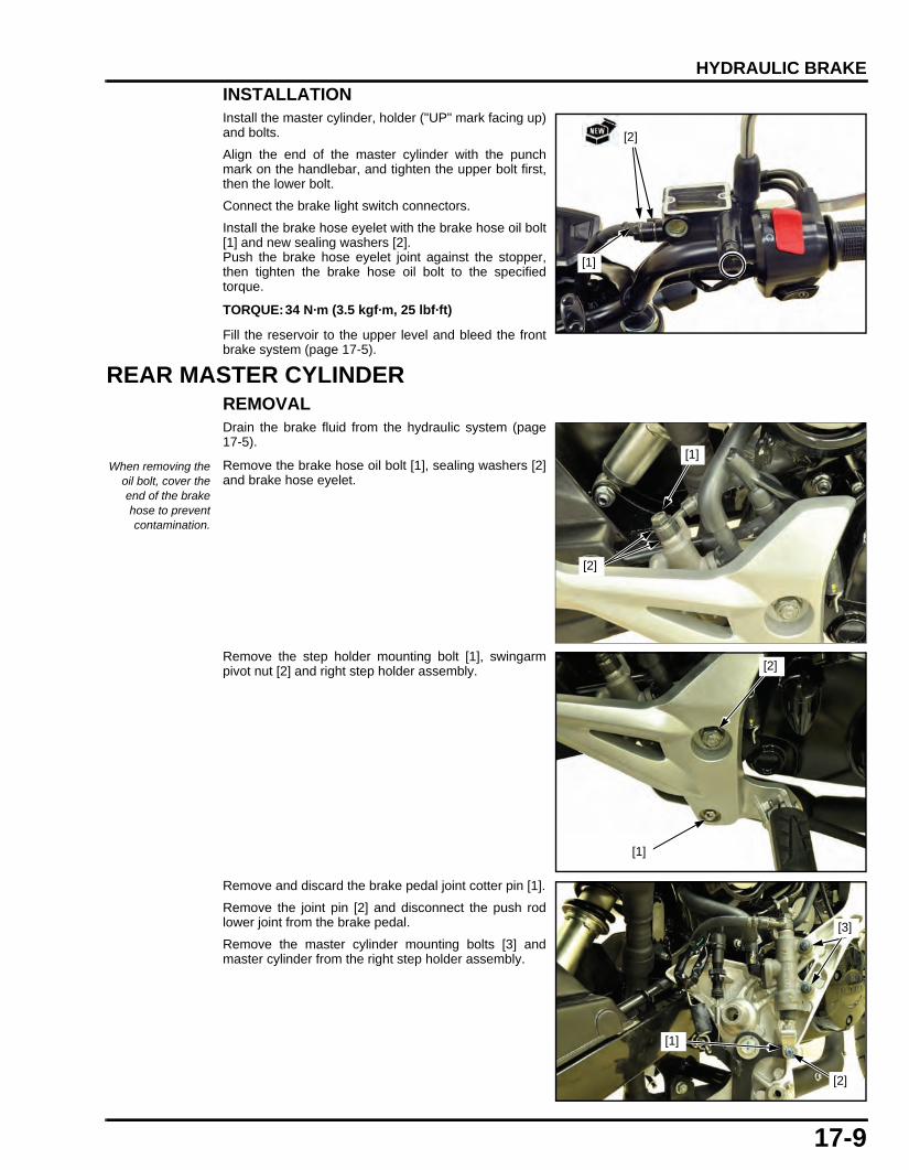
17-9
dummyheaddummyhead
HYDRAULIC BRAKE
INSTALLATIONInstall the master cylinder, holder ("UP" mark facing up)and bolts.
Align the end of the master cylinder with the punchmark on the handlebar, and tighten the upper bolt first,then the lower bolt.
Connect the brake light switch connectors.
Install the brake hose eyelet with the brake hose oil bolt[1] and new sealing washers [2].Push the brake hose eyelet joint against the stopper,then tighten the brake hose oil bolt to the specifiedtorque.
Fill the reservoir to the upper level and bleed the frontbrake system (page 17-5).
REAR MASTER CYLINDERREMOVALDrain the brake fluid from the hydraulic system (page17-5).
Remove the brake hose oil bolt [1], sealing washers [2]and brake hose eyelet.
Remove the step holder mounting bolt [1], swingarmpivot nut [2] and right step holder assembly.
Remove and discard the brake pedal joint cotter pin [1].
Remove the joint pin [2] and disconnect the push rodlower joint from the brake pedal.
Remove the master cylinder mounting bolts [3] andmaster cylinder from the right step holder assembly.
TORQUE:34 N·m (3.5 kgf·m, 25 lbf·ft)
[2]
[1]
When removing theoil bolt, cover theend of the brakehose to preventcontamination.
[1]
[2]
[1]
[2]
[1]
[2]
[3]
61K26000.book Page 9 Friday, July 12, 2013 3:51 PM

17-10
dummyheaddummyhead
HYDRAULIC BRAKE
DISASSEMBLY/ASSEMBLY
Apply silicone grease to the boot groove of the pushrod.
Install the boot securely.
If the push rod joint is reinstalled, adjust the push rodlength so that the distance from the center of the mastercylinder lower mounting hole to the center of the jointpin hole is 64 – 66 mm (2.5 – 2.6 in) as shown.
After adjustment tighten the push rod lock nut to thespecified torque.
PUSH ROD
1.5 N·m (0.2 kgf·m, 1.1 lbf·ft)
HOSE JOINT
SNAP RING
BOOT
17 N·m (1.7 kgf·m, 13 lbf·ft)
BRAKE ROD JOINT
MASTER CYLINDER
RESERVOIR
SPRING
SET PLATE
MASTER PISTON
DIAPHRAGMO-RING
RESERVOIR COVER1.5 N·m (0.2 kgf·m, 1.1 lbf·ft)
BOOT
TORQUE:17 N·m (1.7 kgf·m, 13 lbf·ft)
LOCK NUT
64 – 66 mm(2.5 – 2.6 in)
61K26000.book Page 10 Friday, July 12, 2013 3:51 PM

17-11
dummyheaddummyhead
HYDRAULIC BRAKE
INSPECTIONInspect the following parts for scoring, scratchesdeterioration or damage.
– master cylinder– master piston– piston cups– push rod– Boot– Rod joint
Replace the piston, cups and washer as a set.
Measure the brake disc according to BRAKE SYSTEMSPECIFICATIONS (page 1-9) and replace if necessary.
INSTALLATIONInstall and tighten the master cylinder and mastercylinder mounting bolts [1] to the right step holderassembly.
Connect the push rod lower joint to the brake pedal.Install the joint pin [2] and new cotter pin [3].
Install the right step holder assembly, swingarm pivotnut step holder mounting bolts.Tighten the bolts to the specified torque.
Install the brake hose eyelet with the brake hose oil boltand new sealing washers [1].Push the brake hose eyelet joint against the stopper,then tighten the brake hose oil bolt [2] to the specifiedtorque.
Fill the reservoir to the upper level and bleed the rearbrake system (page 17-5).
FRONT BRAKE CALIPERREMOVAL/INSTALLATIONDrain the brake fluid from the hydraulic system (page17-5).Remove the brake pads (page 17-7).
Remove the brake hose oil bolt [1], sealing washers [2]and brake hose eyelet.
Remove the brake caliper mounting bolts [3] and brakecaliper/bracket assembly.
Install the brake caliper/bracket assembly.
Install new mounting bolts [3] and tighten them to thespecified torque.
TORQUE:Swing arm pivot nut: 54 N·m (5.5 kgf·m,
40 lbf·ft)Step holder mounting bolt: 31 N·m (3.2 kgf·m,
23 lbf·ft)
[2]
[3]
[1]
TORQUE:34 N·m (3.5 kgf·m, 25 lbf·ft)
[2]
[1]
When removing theoil bolt, cover the
end of brake hose toprevent
contamination.
TORQUE:30 N·m (3.1 kgf·m, 22 lbf·ft)
[1][3]
[2]
61K26000.book Page 11 Friday, July 12, 2013 3:51 PM

17-12
dummyheaddummyhead
HYDRAULIC BRAKE
Install the brake hose eyelet between the stoppers withbrake hose oil bolt and new sealing washers [2].Tighten the brake hose oil bolt [1] to the specifiedtorque.
Install the brake pads (page 17-7).
Fill the reservoir to the upper level and bleed the frontbrake system (page 17-5).
DISASSEMBLY/ASSEMBLY
• Do not use high pressure air or bring the nozzle tooclose to the inlet.
• Be careful not to damage the piston sliding surface.
INSPECTIONInspect the following parts for scoring, scratches ordamage.
– caliper cylinders– caliper pistons
Measure the brake disc according to BRAKE SYSTEMSPECIFICATIONS (page 1-9) and replace if necessary.
TORQUE:34 N·m (3.5 kgf·m, 25 lbf·ft)
CALIPER BODY
17 N·m (1.7 kgf·m, 13 lbf·ft)
CALIPER BRACKET
BRAKE PADS
BOOT
CALIPER PISTON
DUST SEAL
PISTON SEAL5.4 N·m (0.6 kgf·m, 4.0 lbf·ft)
O-RING
PAD SPRING
17 N·m (1.7 kgf·m, 13 lbf·ft)
61K26000.book Page 12 Friday, July 12, 2013 3:51 PM

17-13
dummyheaddummyhead
HYDRAULIC BRAKE
REAR BRAKE CALIPERREMOVAL/INSTALLATIONDrain the brake fluid from the hydraulic system (page17-5).Remove the brake pads (page 17-7).
Remove the brake hose oil bolt [1] and sealing washers[2].
Remove the rear wheel (page 16-5).
Remove the brake caliper/bracket assembly.
Install the rear wheel (page 16-7).
Install the brake hose eyelet between the stoppers withbrake hose oil bolt [1] and new sealing washers [2].Tighten the brake hose oil bolt [1] to the specifiedtorque.
Install the brake pads (page 17-7).
Fill the reservoir to the upper level and breed the rearbrake system (page 17-5).
DISASSEMBLY/ASSEMBLY
• Do not use high pressure air or bring the nozzle tooclose to the inlet.
• Be careful not to damage the piston sliding surface.
When removing theoil bolt, cover the
end of brake hose toprevent
contamination.
TORQUE:34 N·m (3.5 kgf·m, 25 lbf·ft)
[1]
[2]
5.4 N·m (0.6 kgf·m, 4.0 lbf·ft)
PAD SPRING
O-RING
17 N·m (1.7 kgf·m, 13 lbf·ft)
RUBBER PLUG
DUST SEAL
PISTON SEAL
CALIPER PISTON
BOOTS
BRAKE PADS
CALIPER BRACKET
CALIPER BODY
61K26000.book Page 13 Friday, July 12, 2013 3:51 PM

17-14
dummyheaddummyhead
HYDRAULIC BRAKE
INSPECTIONInspect the following parts for scoring, scratches ordamage.
– caliper cylinder– caliper piston
Measure the brake disc according to BRAKE SYSTEMSPECIFICATIONS (page 1-9) and replace if necessary.
BRAKE PEDALREMOVAL/INSTALLATIONRemove the step holder mounting bolts [1] andswingarm pivot nut [2] and right step holder assembly.
Unhook the brake light switch spring [1] from the brakepedal return spring [2].
Remove the snap ring [3], washer and brake pedal.
[1]
[2]
[2]
[3]
[1]
61K26000.book Page 14 Friday, July 12, 2013 3:51 PM
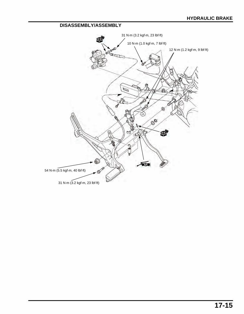
17-15
dummyheaddummyhead
HYDRAULIC BRAKE
DISASSEMBLY/ASSEMBLY
54 N·m (5.5 kgf·m, 40 lbf·ft)
31 N·m (3.2 kgf·m, 23 lbf·ft)
31 N·m (3.2 kgf·m, 23 lbf·ft)
10 N·m (1.0 kgf·m, 7 lbf·ft)
12 N·m (1.2 kgf·m, 9 lbf·ft)
61K26000.book Page 15 Friday, July 12, 2013 3:51 PM

MEMO
dummyheaddummyhead
61K26000.book Page 16 Friday, July 12, 2013 3:51 PM

18-1
18
dummytext
18. BATTERY/CHARGING SYSTEM
SERVICE INFORMATION···························18-2
TROUBLESHOOTING·································18-3
SYSTEM LOCATION···································18-4
SYSTEM DIAGRAM ···································18-4
BATTERY···················································· 18-5
CHARGING SYSTEM INSPECTION ·········· 18-5
ALTERNATOR CHARGING COIL·············· 18-6
REGULATOR/RECTIFIER ·························· 18-7
61K26000.book Page 1 Friday, July 12, 2013 3:51 PM

18-2
dummyheaddummyhead
BATTERY/CHARGING SYSTEMBATTERY/CHARGING SYSTEM
SERVICE INFORMATIONGENERAL
• Always turn OFF the ignition switch before disconnecting any electrical component. • Some electrical components may be damaged if terminals or connectors are connected or disconnected while the ignition switch
is ON position and current is present.
• For extended storage, remove the battery, give it a full charge, and store it in a cool, dry space. For maximum service life,charge the stored battery every two weeks.
• For a battery remaining in a stored motorcycle, disconnect the negative battery cable from the battery terminal. • The maintenance free (MF) battery must be replaced when it reaches the end of its service life. • The battery can be damaged if overcharged or undercharged, or if left to discharge for long period. These same conditions
contribute to shortening the "life span" of the battery. Even under normal use, the performance of the battery deteriorates after 2– 3 years.
• Battery voltage may recover after battery charging, but under heavy load, the battery voltage will drop quickly and eventually dieout. For this reason, the charging system is often suspected as the problem. Battery overcharge often results from problems inthe battery itself, which may appear to be an overcharging symptom. If one of the battery cells is shorted and battery voltagedoes not increase, the regulator/rectifier supplies excess voltage to the battery. Under these conditions, the electrolyte levelgoes down quickly.
• Before troubleshooting the charging system, check for proper use and maintenance of the battery. Check if the battery isfrequently under heavy load, such as having the turn signal and brake lights on for long periods of time without riding themotorcycle.
• The battery will self-discharge when the motorcycle is not in use. For this reason, charge the battery every two weeks to preventsulfation from occurring.
• When checking the charging system, always follow the steps in the troubleshooting.
BATTERY CHARGING
• Turn power ON/OFF at the charger, not at the battery terminal. • For battery charging, do not exceed the charging current and time specified on the battery. Using excessive current or extending
the charging time may damage the battery. • Quick charging should only be done in an emergency; slow charging is preferred.
BATTERY TESTING
Refer to the instruction of the Operation Manual for the recommended battery tester for details about battery testing. Therecommended battery tester puts a "load" on the battery so that the actual battery condition during load can be measured.
• The battery gives off explosive gases; keep sparks, flames and cigarettes away. Provide adequate ventilation when charging.
• The battery contains sulfuric acid (electrolyte). Contact with skin or eyes may cause severe burns. Wear protective clothing and a face shield.– If electrolyte gets on your skin, flush with water.– If electrolyte gets in your eyes, flush with water for at least 15 minutes and call a physician immediately.
• Electrolyte is poisonous.– If swallowed, drink large quantities of water or milk and call your local Poison Control Center or a call a physician
immediately.
Recommended battery tester: BM-210 or BATTERY MATE or equivalent
61K26000.book Page 2 Friday, July 12, 2013 3:51 PM

18-3
dummyheaddummyhead
BATTERY/CHARGING SYSTEM
SPECIFICATIONS
TROUBLESHOOTING
ITEM SPECIFICATIONSBattery Type YTZ5S
Capacity 12 V - 3.5 Ah (10 HR)Current leakage 0.01 mAVoltage(20°C/68°F)
Fully charged 13.0 – 13.2 VNeeds charging Below 12.4 V
Charging current Normal 0.5 A/5 – 10 hQuick 2.5 A/1 h
Alternator Capacity 0.18 kW/5,000 min-1 (rpm)Charging coil resistance (20°C/68°F) 0.2 – 1.0 Ω
Unusual condition Probable cause (Check in numerical order)Battery Battery is damaged or weak 1. Faulty battery
2. Current leakage higher than specified value– Faulty ignition switch– Shorted wire harness
3. Faulty alternator charging coil4. Faulty regulator/rectifier5. Open circuit or loose connection in the wire harness
61K26000.book Page 3 Friday, July 12, 2013 3:51 PM

18-4
dummyheaddummyhead
BATTERY/CHARGING SYSTEM
SYSTEM LOCATION
SYSTEM DIAGRAM
ALTERNATOR
BATTERY
REGULATOR/RECTIFIER
MAIN FUSE 15 A
G:R:W:Y:
GreenRedWhiteYellowRG
G R/Y
BATTERY
ALTERNATOR
MAIN FUSE 15 A
REGULATOR/RECTIFIER
R W Y
To IGNITION SWITCH
To LIGHTSSWITCH
61K26000.book Page 4 Friday, July 12, 2013 3:51 PM

18-5
dummyheaddummyhead
BATTERY/CHARGING SYSTEM
BATTERYREMOVAL/INSTALLATION • Always turn the ignition switch OFF before removing
the battery. • Always disconnect the negative terminal first. • Connect the positive (+) cable to the battery first,
then connect the negative (–) cable.
Remove the seat (page 2-3).
Remove the bolt [1] and battery holder plate [2] andbattery.
Installation is in the reverse order of removal.
• Install the battery holder plate by aligning its hookwith the slit of the rear fender.
• For digital clock setting procedure (page 19-6).
VOLTAGE INSPECTIONMeasure the battery voltage using a commerciallyavailable digital multimeter.
• When measuring the battery voltage after charging,leave it for least 30 minutes, or the accurate resultscannot be obtained because the battery voltagefluctuates just after charging.
BATTERY TESTINGRefer to the instructions that are appropriate to thebattery testing equipment available to you.
CHARGING SYSTEM INSPECTIONCURRENT LEAKAGE TESTRemove the seat (page 2-3).
Turn the ignition switch OFF and disconnect thenegative (–) cable [1] from the battery.Connect the ammeter (+) probe to the negative cableand the ammeter (–) probe to the battery (–) terminal.With the ignition switch OFF, check for current leakage.
• When measuring current using a tester, set it to ahigh range, and then bring the range down to anappropriate level. Current flow higher than the rangeselected may blow the fuse in the tester.
• While measuring current, do not turn the ignitionswitch ON, A sudden surge of current may blow thefuse in the tester.
[1][2]
VOLTAGE (20°C/68°F):Fully charged: 13.0 – 13.2 VNeeds charging:Below 12.4 V
(–)(+)
TOOL:Battery tester BM-210, BATTERY MATE or
equivalent
[1]
(–)
(+)
61K26000.book Page 5 Friday, July 12, 2013 3:51 PM

18-6
dummyheaddummyhead
BATTERY/CHARGING SYSTEM
If current leakage exceeds the specified value (page 1-9), a shorted circuit is the probable cause.Locate the short by disconnecting connections one byone and measuring the current.
CHARGING VOLTAGE INSPECTIONRemove the seat (page 2-3).
Make sure the battery is in good condition beforeperforming this inspection.
Warm up the engine to normal operating temperature.Stop the engine and connect the multimeter as shown.
To prevent a short, make absolutely certain which arethe positive and negative terminals or cables.
Connect a tachometer according to its manufacturer’sinstructions.
Restart the engine.Measure the voltage on the multimeter when the engineruns at 5,000 min-1 (rpm).
ALTERNATOR CHARGING COILINSPECTIONRemove the right shroud (page 2-4).
Disconnect the alternator connector [1].
Check the resistance between the alternator 4Pconnector [1] White and Green wire terminals of thealternator side.
Replace the stator if the resistance is out ofspecification.
Install the right shroud (page 2-4).
Do not disconnectthe battery or any
cable in thecharging system
without firstswitching OFF the
ignition switch.Failure to follow this
precaution candamage the tester
or electricalcomponents.
STANDARD: Measured BV < Measured CV < 15.5 V • BV = Battery Voltage (page 18-5) • CV = Charging Voltage
(–)(+)
[1]
STANDARD: 0.2 – 1.0 Ω (at 20°C/68°F)
[1]
W G
61K26000.book Page 6 Friday, July 12, 2013 3:51 PM

18-7
dummyheaddummyhead
BATTERY/CHARGING SYSTEM
REGULATOR/RECTIFIERSYSTEM INSPECTIONRemove the shroud (page 2-4).
Turn the ignition switch OFF.Disconnect the regulator/rectifier connector 6P [1].
Check it for loose contact or corroded terminals.
If the charging voltage reading (page 18-6) is out of thespecification, inspect the regulator/rectifier connectorterminals (wire harness side) as follows:
If all components of the charging system is normal andthere are no loose connections at the regulator/rectifierconnector, replace the regulator/rectifier unit.
Install the right shroud (page 2-4).
REMOVAL/INSTALLATIONRemove the shroud (page 2-4).
Turn the ignition switch OFF.
Disconnect the regulator/rectifier connector 6P [1].
Remove the bolts [2] and regulator/rectifier from theframe.
Installation is in the reverse order of removal.
Item Terminal SpecificationBattery charging line
Red/yellow (+) and Ground (–)
Battery voltage should appear
Charging coil line
White and Green 0.2 – 1.0 Ω(at 20°C/68°F)
Ground line Green and Ground Continuityshould exist
[1]
[2]
[1]
61K26000.book Page 7 Friday, July 12, 2013 3:51 PM

MEMO
dummyheaddummyhead
61K26000.book Page 8 Friday, July 12, 2013 3:51 PM

19-1
19
dummytext
19. LIGHTS/METERS/SWITCHES
SERVICE INFORMATION···························19-2
SYSTEM LOCATION···································19-3
HEADLIGHT ················································19-4
TURN SIGNAL LIGHT·································19-4
BRAKE/TAILLIGHT·····································19-4
LICENSE LIGHT··········································19-5
HORN···························································19-5
COMBINATION METER······························19-6
FUEL GAUGE/FUEL LEVEL SENSOR······························· 19-7
IGNITION SWITCH······································ 19-8
HANDLEBAR SWITCHES ·························· 19-9
BRAKE LIGHT SWITCH ····························· 19-9
NEUTRAL SWITCH ·································· 19-10
SIDESTAND SWITCH······························· 19-10
VS SENSOR·············································· 19-11
TURN SIGNAL RELAY ····························· 19-11
61K26000.book Page 1 Friday, July 12, 2013 3:51 PM

19-2
dummyheaddummyhead
LIGHTS/METERS/SWITCHESLIGHTS/METERS/SWITCHES
SERVICE INFORMATIONGENERAL • Be sure to install the dust cover after replacing the bulb. • Check the battery condition before performing any inspection that requires proper battery voltage. • A continuity test can be made with the switches installed on the motorcycle. • The following color codes are used throughout this section.
SPECIFICATIONS
TORQUE VALUESLIGHTS/METERS/SWITCHES
Bu = Blue G = Green Lg = Light green R = RedBl = Black Gr = Gray O = Orange W = WhiteBr = Brown Lb = Light blue P = Pink Y = Yellow
ITEM SPECIFICATIONBulbs Headlight (High/Low) 12 V - 35/35 W
Brake/tail light LEDTurn signal light Front 12 V - 21/5 W x 2
Rear 12 V - 21 W x 2 License light 12 V - 5 WMeter light LEDTurn signal indicator LEDHigh beam indicator LEDNeutral indicator LED
Fuse Main fuse 15 ASub fuse 10 A
ITEM Q'TYTHREAD TORQUE
REMARKSDIA. (mm) N·m (kgf·m, lbf·ft)
Tail light unit mounting nut 2 6 10 (1.0, 7)Combination meter screw 8 3 1.0 (0.1, 0.7)
61K2600019.fm Page 2 Monday, July 15, 2013 10:09 AM

19-3
dummyheaddummyhead
LIGHTS/METERS/SWITCHES
SYSTEM LOCATION
FRONT BRAKE LIGHT SWITCH
HORN
FUEL LEVEL SENSOR
SPEEDOMETER
TURN SIGNAL LIGHT SWITCH
STARTER SWITCH
REAR BRAKE LIGHT SWITCH
HORN SWITCH
TURN SIGNAL RELAY
61K2600019.fm Page 3 Monday, July 15, 2013 10:09 AM

19-4
dummyheaddummyhead
LIGHTS/METERS/SWITCHES
HEADLIGHTHEADLIGHT BULB REPLACEMENTRemove the headlight assembly (page 2-7).
Disconnect the headlight connector.
Remove the dust cover [1].Unhook the bulb retainer [2] and remove the headlightbulb [3].Remove the socket and headlight bulb [3].
• Wear clean gloves while replacing the bulb. Do notput fingerprints on the headlight bulb, as they maycreate hot spots on the bulb and cause it to fail.
• If you touch the bulb with your bare hands, clean itwith a cloth moistened with alcohol to prevent itsearly failure.
Installation is in the reverse order of the removal.
TURN SIGNAL LIGHTBULB REPLACEMENTRemove the screw [1] and turn signal light lens [2] byreleasing its tab.
While pushing in the bulb [3], turn it counterclockwise toremove it.
Installation is in the reverse order of removal.
BRAKE/TAILLIGHTREMOVAL/INSTALLATIONRemove the body cover (page 2-6).
Disconnect the brake/taillight connector and release thewire from the clamps.
Remove the two nuts [1], washers [2] and brake/taillightunit [3] by releasing its boss from the grommet of therear fender.
Installation is in the reverse order of removal.
[2]
[3]
[1]
[3]
[1]
[2]
[1]/[2]
[3]
61K2600019.fm Page 4 Monday, July 15, 2013 10:09 AM

19-5
dummyheaddummyhead
LIGHTS/METERS/SWITCHES
LICENSE LIGHTBULB REPLACEMENTRemove the two screws [1], license light lens [2] andbulb [3].
Install a new bulb in the reverse order of removal.
HORNINSPECTIONDisconnect the horn wire connectors [1].Connect the 12 V battery to the horn terminals.
The horn is normal if it sounds when the 12 V battery isconnected to the horn terminals.
REMOVAL/INSTALLATIONDisconnect the horn wire connectors [1].
Remove the following:
– Bolt [2]– Horn
Installation is in the reverse order of removal.
[2]
[1]
[3]
[1]
[1]
[2]
61K2600019.fm Page 5 Monday, July 15, 2013 10:09 AM

19-6
dummyheaddummyhead
LIGHTS/METERS/SWITCHES
COMBINATION METERREMOVAL/INSTALLATIONRemove the headlight assembly (page 2-7):
Remove the three screws [1] and combination meter.
Disconnect the meter connector [2].
DISASSEMBLY/ASSEMBLYRemove the combination meter screw then, disassemble the combination meter.
DIGITAL CLOCK SET PROCEDURE1. Turn the ignition switch on.2. Press and hold the SEL [1] and SET [2] buttons until
the hour digits [3] start blinking.3. Press the SEL button until the desired hour is
displayed.4. Press and hold to advance the hour fast.5. Press the SET button. The minute digits start
blinking.6. Press the SEL button until the desired minute is
displayed.7. Press and hold to advance the minute fast.8. Press the SET button. The clock is set.
• The adjustment can also be set by turning theignition switch off.
• If the SET button was not pressed during theadjustment, and no buttons were pressed for about30 seconds, the display will stop blinkingautomatically and the adjustment will be cancelled.
[1]
[2]
0.5 N·m (0.1 kgf·m, 0.4 lbf·ft)
[2][1] [3]
61K2600019.fm Page 6 Monday, July 15, 2013 10:09 AM

19-7
dummyheaddummyhead
LIGHTS/METERS/SWITCHES
FUEL GAUGE/FUEL LEVEL SENSORFUEL LEVEL SENSOR REMOVAL/INSTALLATIONRemove the fuel pump unit.
Disconnect the fuel level sensor Red [1] and Black [2]wire connectors.
Release the wires from the guides [3] of the fuel pumpunit.
Remove the fuel level sensor [1] from the fuel pump unitby releasing the three hooks [2].
Installation is in the reverse order of removal.
FUEL LEVEL SENSOR INSPECTIONRemove the fuel level sensor.
Connect the ohmmeter to the fuel level sensor wireterminals.
Inspect the resistance of the float at the full and emptypositions.
Replace the fuel level sensor if it is out of specification.
Install the fuel level sensor.
[1] [2]
[3]
[1]
[2]
Float position: FULL EMPTYResistance: 6 – 10 Ω 266 – 274 Ω
Empty
Full
61K2600019.fm Page 7 Monday, July 15, 2013 10:09 AM

19-8
dummyheaddummyhead
LIGHTS/METERS/SWITCHES
IGNITION SWITCHINSPECTIONRemove the headlight assembly.
Turn the ignition switch "OFF".
Disconnect the ignition switch connector 4P [1].
Check for continuity between the switch side connectorterminals in each switch position according to the chart(page 20-2).
Connect the ignition switch connector 4P [1].
Install the headlight assembly.
REMOVAL/INSTALLATIONRemove the headlight assembly (page 2-7).
Disconnect the ignition switch connector [1].
Loosen the top bridge pinch bolts [1].
Remove the steering stem nut [2], washer [3] and topbridge.
Remove the screw [1] and ignition switch [2].
Install the ignition switch and tighten the new screw.
Installation is in the reverse order of removal.
[1]
[1]
[1]
[2]/[3]
TORQUE:Steering stem nut: 88 N·m (9.0 kgf·m, 65 lbf·ft)Top bridge pinch bolt: 27 N·m (2.8 kgf·m, 20 lbf·ft)
[1]
[2]
61K2600019.fm Page 8 Monday, July 15, 2013 10:09 AM

19-9
dummyheaddummyhead
LIGHTS/METERS/SWITCHES
HANDLEBAR SWITCHESRIGHT HANDLEBAR SWITCHCheck for continuity between the switch side connectorterminals in each switch position.
Continuity should exist between the color coded wire asshown in the wiring diagram.
LEFT HANDLEBAR SWITCHCheck for continuity between the switch side connectorterminals in each switch position.
Continuity should exist between the color coded wire asshown in the wiring diagram.
BRAKE LIGHT SWITCHFRONTDisconnect the front brake light switch wire connectorsand check for continuity between the switch terminals[1].
There should be continuity with the brake leversqueezed and no continuity with the lever released.
[1]
[2]
[3]
[1]
[2]
[1]
61K2600019.fm Page 9 Monday, July 15, 2013 10:09 AM

19-10
dummyheaddummyhead
LIGHTS/METERS/SWITCHES
REARDisconnect the rear brake light switch wire connectors[1].
Check for continuity between the switch side connectorterminals.
There should be continuity with the brake pedal appliedand no continuity with the pedal released.
NEUTRAL SWITCHINSPECTIONCheck the operation of neutral indicator at each gearposition.If the indicator bulbs are normal check as follows:
Disconnect the neutral switch connector [1].
Check the continuity between the neutral switchconnector and ground.
There should be continuity with the gear is neutral andno continuity with the any gear position.
REMOVAL/INSTALLATIONRemove the bolt, spring cap, and neutral switch.
Installation is the reverse of removal.
SIDESTAND SWITCHINSPECTIONDisconnect the sidestand switch 3P connector.
Check the continuity at the sidestand 3P connector ofthe switch side connector.
There should be continuity with the sidestand retractedand no continuity with the sidestand lowered.
[1]
[1]
61K2600019.fm Page 10 Monday, July 15, 2013 10:09 AM

19-11
dummyheaddummyhead
LIGHTS/METERS/SWITCHES
REMOVAL/INSTALLATIONRemove the bolt [1] and sidestand switch [2].
Install the sidestand switch and tighten the new bolt.
Align the sidestand switch groove with the frame pin.
VS SENSORCheck for loose or poor contact of the VS sensorconnector.
Disconnect the VS sensor connector.
Turn the ignition switch ON and engine stop switch " ".
Measure the voltage between the VS sensor terminalsat the wire side.
If the battery voltage appears, replace the VS sensor.
If there is no voltage, check the following:
– Pink wire open circuit– Green wire open circuit– Combination meter
TURN SIGNAL RELAYINSPECTIONCheck the following:
– Battery condition– Ignition switch and turn signal light switch function– Loose connectors– Fuse
If above items are all normal, check the following:
Remove the headlight assembly(page 2-7).
Disconnect the turn signal relay 2P connector [1].Remove the turn signal relay [2] from the speedometer.
TORQUE:Sidestand switch bolt: 10 N·m (1.0 kgf·m, 7 lbf·ft) [1]
[2]
Align
CONNETION: Pink (+) - Green (-)STANDARD: Battery voltage
[1]
[2]
61K2600019.fm Page 11 Monday, July 15, 2013 10:09 AM

19-12
dummyheaddummyhead
LIGHTS/METERS/SWITCHES
Short the Black and Gray terminals of the harness side2P connector [1] with the jumper wire.
Turn the ignition switch ON.Check the turn signal light by moving the turn signallight switch [2] to the right and left.
• If the turn signal light does not come on, there isopen circuit in wire harness.
• If the lights come on, the circuit is normal.Replace the turn signal relay.
Install the removed parts in the reverse order ofremoval.
[1]
From IGNITION SWITCH
[2]
Bl Gr O
Lb
G
61K2600019.fm Page 12 Monday, July 15, 2013 10:09 AM

2-1
2
dummytext
2. BODY PANELS/EXHAUST SYSTEM
SERVICE INFORMATION·····························2-2
TROUBLESHOOTING···································2-2
FRONT FENDER···········································2-3
SEAT······························································2-3
SHROUD························································2-4
BODY COVER/TAIL COVER ························2-6
FUEL TANK COVER·····································2-6
HEADLIGHT·················································· 2-7
REAR INNER FENDER································· 2-7
REAR FENDER A/REAR FENDER STAY ·································· 2-8
REAR FENDER B ········································· 2-9
DRIVE CHAIN COVER·································· 2-9
EXHAUST PIPE/MUFFLER ························ 2-10
61K26000.book Page 1 Friday, July 12, 2013 3:51 PM

2-2
dummyheaddummyhead
BODY PANELS/EXHAUST SYSTEMBODY PANELS/EXHAUST SYSTEM
SERVICE INFORMATIONGENERAL • Serious burns may result if the exhaust system is not allowed to cool before components are removed or serviced. • When installing the exhaust system, loosely install all of the exhaust pipe fasteners. Always tighten the exhaust pipe joint nuts
first, then tighten the mounting bolt and nut. • Always inspect the exhaust system for leaks after installation.
TORQUE VALUESBODY PANELS/EXHAUST SYSTEM
TROUBLESHOOTINGExcessive exhaust noise • Broken exhaust system • Exhaust gas leak
Poor performance • Deformed exhaust system • Exhaust gas leak • Clogged muffler
ITEM Q'TYTHREAD TORQUE
REMARKSDIA. (mm) N·m (kgf·m, lbf·ft)
Body cover and tailcover mounting screw 4 4 0.9 (0.1, 0.7)Exhaust pipe cover bolt 2 6 14 (1.4, 10)Exhaust pipe mounting nut 2 8 27 (2.8, 20)Exhaust pipe mounting bolt 1 8 27 (2.8, 20)Exhaust pipe stud bolt 2 8 – See page 2-10Front fender mounting bolt 6 6 12 (1.2, 9)Front cowl mounting bolt 4 6 12 (1.2, 9)Muffler band bolt 1 8 20 (2.0, 15)Muffler mounting bolt 1 8 27 (2.8, 20)Muffler mounting nut 1 8 27 (2.8, 20)Muffler protector bolt 1 6 14 (1.4, 10)Rear fender stay bolt 2 8 31 (3.2, 23)Seat lock bracket bolt 2 6 14 (1.4, 10)Shroud screw 3 5 4.2 (0.4, 3.1)Shroud tapping screw 20 4 0.9 (0.1, 0.7)Sidestand lock nut 1 10 30 (3.1, 22) U-nut Sidestand pivot bolt 1 10 10 (1.0, 7)Sidestand switch bolt 1 10 10 (1.0, 7) ALOC bolt; replace
with a new one.
61K26000.book Page 2 Friday, July 12, 2013 3:51 PM

2-3
dummyheaddummyhead
BODY PANELS/EXHAUST SYSTEM
FRONT FENDERREMOVAL/INSTALLATIONRemove the following:
– Cap nut [1] and brake hose clamp [2]– Bolts [3], collars [4]/[5] and grommets [6]
Remove the front fender from the fork legs.
Installation is in the reverse order of removal.
Remove the nut [1] and reflector [2].
Remove the nut [3] and reflector stay [4].
SEATREMOVAL/INSTALLATIONREMOVAL
Insert the ignition key into the seat lock.
Turn it clockwise, then pull the seat up and back.
INSTALLATION
Insert the prongs into the stays on the frame.
Push forward and down on the rear of the seat until itlocks in place.
[1][2]
[6]
[3]
[5]
[4]
61K26000.book Page 3 Friday, July 12, 2013 3:51 PM
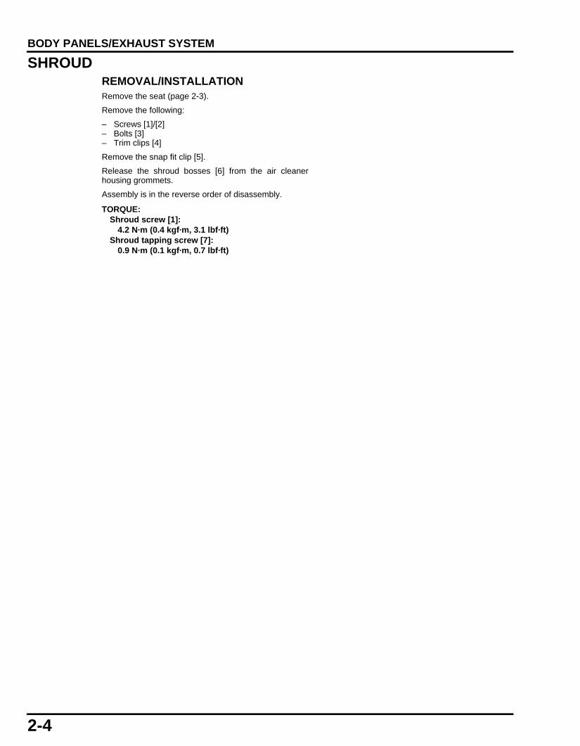
2-4
dummyheaddummyhead
BODY PANELS/EXHAUST SYSTEM
SHROUDREMOVAL/INSTALLATIONRemove the seat (page 2-3).
Remove the following:
– Screws [1]/[2]– Bolts [3]– Trim clips [4]
Remove the snap fit clip [5].
Release the shroud bosses [6] from the air cleanerhousing grommets.
Assembly is in the reverse order of disassembly.
TORQUE:Shroud screw [1]:
4.2 N·m (0.4 kgf·m, 3.1 lbf·ft)Shroud tapping screw [7]:
0.9 N·m (0.1 kgf·m, 0.7 lbf·ft)
61K26000.book Page 4 Friday, July 12, 2013 3:51 PM

2-5
dummyheaddummyhead
BODY PANELS/EXHAUST SYSTEM
[4]
[4]
[1]
[2][3]
[1]
[1]
[4]
[1]
[1]
[1]
[1]
[6]
[6]
[5]
[5]
[7]
61K26000.book Page 5 Friday, July 12, 2013 3:51 PM

2-6
dummyheaddummyhead
BODY PANELS/EXHAUST SYSTEM
BODY COVER/TAIL COVERREMOVAL/INSTALLATION Remove the following:
– Shroud (page 2-4)– Bolts [1]– Screws [2]/[3]– Trim clips [4]– Body cover
Remove the screws and separate the body cover andtail cover [5].
Installation is in the reverse order of removal.
FUEL TANK COVERREMOVAL/INSTALLATIONRemove the shroud (page 2-4).
Remove the four screws[1] and fuel tank cover [2].
Installation is in the reverse order of removal.
TORQUE:Body cover/tail cover mounting screw [2]:
0.9 N·m (0.1 kgf·m, 0.7 lbf·ft)
[5]
[3]
[1]
[1]
[4]
[2]
[1]
[2]
61K26000.book Page 6 Friday, July 12, 2013 3:51 PM

2-7
dummyheaddummyhead
BODY PANELS/EXHAUST SYSTEM
HEADLIGHT
REMOVAL/INSTALLATIONRemove the bolts [1].
Disconnect the headlight connector [2] then, remove theheadlight assembly.
DISASSEMBLY/ASSEMBLY– Aiming adjust screw (page 3-12)– Headlight form the headlight cover [4]– Front turn signal light
REAR INNER FENDERREMOVAL/INSTALLATIONRemove the screws [1] and rear inner fender.
Installation is in the reverse order of removal.
[1]
[1]
[2]
TORQUE:Front cowl mounting screw [1]:
12 N·m (1.2 kgf·m, 9 lbf·ft)
TORQUE: 0.9 N·m (0.1 kgf·m, 0.7 lbf·ft)
[1]
61K26000.book Page 7 Friday, July 12, 2013 3:51 PM

2-8
dummyheaddummyhead
BODY PANELS/EXHAUST SYSTEM
REAR FENDER A/REAR FENDER STAYREMOVAL/INSTALLATIONRemove the following:
– Rear inner fender (page 2-7)– Body cover (page 2-6)
Disconnect the license light wire connectors [1] and rearturn signal light connectors [2].
Remove the bolts[3], rear fender assembly.
Remove the bolts [4] and rear turn signal light.
Remove the bolt [5] then, separate the fender A [6] fromthe rear fender stay [7].
Installation is in the reverse order of removal.
DISASSEMBLY/ASSEMBLYRemove the nut [1], collar [2] and license light [3].
Remove the nut [4] and reflector [5] from the rear fenderA.
Assembly is in the reverse order of disassembly.
Align the reflector tab with the hole of the rear fender A.
[3]
[6]
[7]
[1][2]
[5]
31 N·m (3.2 kgf·m, 23 lbf·ft)
[4]
[4][5]
[1][2]
[3]
61K26000.book Page 8 Friday, July 12, 2013 3:51 PM

2-9
dummyheaddummyhead
BODY PANELS/EXHAUST SYSTEM
REAR FENDER BREMOVAL/INSTALLATIONRemove the following:
– Battery – Rear fender A/rear fender stay (page 2-8)
Disconnect the tail light connector [1].
Release the fuse box from the rear fender B.
Remove the battery cover by releasing the tabs fromthe slots of the rear fender B.
Remove the bolts and release the tab of the rear fenderB from the slot of the seat lock bracket.Remove the rear fender B by pulling it rearward.
Installation is in the reverse order of removal.
Install the rear fender B by aligning its front lowergroove with the seat rail brace.
DRIVE CHAIN COVERREMOVAL/INSTALLATIONRemove the bolts and drive chain cover by pulling itrearward and releasing the tabs [1] from the slots [2] onthe swingarm.
Installation is in the reverse order of removal.
[1]
[1][2]
61K26000.book Page 9 Friday, July 12, 2013 3:51 PM

2-10
dummyheaddummyhead
BODY PANELS/EXHAUST SYSTEM
EXHAUST PIPE/MUFFLERREMOVAL/INSTALLATIONLoosen the bolt [1].
Remove the following:
– Bolt [2]– Nut [3]– Muffler [4]– Exhaust pipe mounting nut [5]– Bolt [6]– Exhaust pipe [7].
Installation is in the reverse order of removal.
EXHAUST PIPE STUD BOLT REPLACEMENTThread two nuts to the stud bolt and tighten themtogether, then use a wrench on them to turn the studbolt out.
Install and tighten new stud bolts into the cylinder headto the specified torque.
After tightening the stud bolts, check that the lengthfrom the bolt head to the cylinder head surface is withinspecification.
GASKETGASKET
WASHER
[2]
[3]
WASHER
RUBBER[4]
RUBBER
14 N·m (1.4 kgf·m, 10 lbf·ft)
27 N·m (2.8 kgf·m, 20 lbf·ft)
27 N·m (2.8 kgf·m, 20 lbf·ft)
[1] 20 N·m (2.0 kgf·m, 15 lbf·ft)
27 N·m (2.8 kgf·m, 20 lbf·ft)
27 N·m (2.8 kgf·m, 20 lbf·ft)
14 N·m (1.4 kgf·m, 10 lbf·ft)
[6]
[7]
[5]
MUFFLER PROTECTOR
MUFFLER COVER
WASHER
TORQUE:11 N·m (1.1 kgf·m, 8 lbf·ft)
27.5 ± 1.0 mm(1.08 ± 0.04 in)
61K26000.book Page 10 Friday, July 12, 2013 3:51 PM

20-1
20
dummytext
20. WIRING DIAGRAMS
WIRING DIAGRAM······································20-2
61K26000.book Page 1 Friday, July 12, 2013 3:51 PM

20-2
dummyheaddummyhead
WIRING DIAGRAMSWIRING DIAGRAMS
WIRING DIAGRAM
14P
4P
3P (Lb)
3P (O)
6P
2P
16P
9P
4P
2P
5P
3P(G)
6P
2P
3P (Bl)
4P
4P
4P(R)
1P3P
2P2P
33P
2P5P
3P
BATST
BATIG
BAT1
UP
DO
WN
VO1
BAT2VO2
BAT
HO
LOPL
PRP
HL
HI
A-1IGPA-2LGA-3O2A-4SG1(TH)A-5THLA-6VCCA-7PRCA-8FFPA-9PG1
A-10PG2A-11IGPLSA-12PCPA-13-A-14TAA-15SCSA-16INJA-17-A-18-A-19PCSA-20SOL VA-21-A-22FI-IND2A-23PCMA-24TO
VCCTHR
BATHO
SG
A-25SSTANDA-26BAA-27-A-28TACHOA-29NLSWA-30K-LINEA-31SG2(TO)A-32SG3(TA)A-33-
SP
EE
D IN
PU
TFU
EL IN
PU
TTU
RN
LN
EU
TRA
LH
IGH
-BE
AMTA
TUR
N R
BATT
IGN
(VC
C) FI
SP S
EN
SO
R 12V
SP S
EN
SO
R G
ND
GN
D
12345678910111213141516
R
LW
N
Gr
LbO
CO
LOR
OFF
ON
RB
l/YC
OLO
R
WR
LV
O1
BAT1
R/Y
Bl/R
VO
2B
AT2
(N)
Bl
Lb/WO
/W
FRE
E
PU
SH
Bl/W
Bl/B
u
CO
LOR
CO
LOR
CO
LOR
Y/R
Bl/B
u
YB
uW
PP
RP
LH
LLO
HI
IGS
TB
ATB
AT
FRE
E
PU
SH
Bl
CO
LOR
Lg
HO
BAT
2P(Gr)
2P
Bl/BuBl/WY/R
G/Y
R G/RY/R R/W
G/Bl
G G
G G
G
G/Bl
Bl/R R/YBl/Y R
Bl/R R/Y
G G/W G G/W
Bl/Y R
Bl G/Y Bl G/Y
Bl/W Bl/WBl/Y
Bl Bl
R R
G
G
RR/Y
Bl/R
G
R/W
G
R/W
Bl
R/YG
RY
WY
Lg/RLg/RG/R
G GG GG G
Bl/BuBl/WY/R Bl/Bu
G/YBl
BrY/RY G/OBl/O
Bu/YP/Bu GG
P/GBu
R/BuY/BuW/Y
Y/Bl
W/Bu
W/Bu
Y/O
G/O YG/O
G/R Y/G
G/BlBl/Bu
Y/G
Lb Bu
Lg/RO
GW
/Bu
P
Bl
R/Y
G/B
l
Y/W
W/R
G/Y
GB
l
Lb G Y
O
G/Y
GB
l
Lb G
O G
Y
YG
GLb
GO
OLb W
G BuO
Bl
Gr
Lb/WO
/W
Lb WG BuO
Lb/WG
OG
G
OG
Lb
O/W
Lb
O/W
Bl
Gr
WG Bu
Bl
Gr
O/W Lb/WLbO
LgBlBu YW
GW/R
GLg
Bl/WG/Bl Y/W
P
Bl/BuP/G
Bl/BuBl/Bu
Bl/WP/Bu
Br
G/RG/W
O/W Lb/WLb
LgBlBu YW
GW/RP
G/RG/W
O/W BlLb/WLb GrO
LgBlBu YW
G/RG/W
GW
Lg/R Lg/R
Bu/YW/Y
GW Bu/YW/Y
Bl/OBl/OG
G/O YY/R
Bl/WY/O
R/BuBl/Bu
G/BlBu YBl/W
G
G
G
W
Bu/YW/Y
G/OY/Bu
W/BuG/O
Lb/W
GrO GrO
Lb/WO
/W
G/W
Bl/WY/Bl
EC
M
HO
RN
BA
NK
AN
GLE
SE
NS
OR
NE
UTR
AL
SW
ITCH
FUE
L PU
MP
FUE
LIN
JEC
TOR
IGN
ITION
CO
ILS
TP SE
NS
OR
IAT SE
NS
OR
ALTE
RN
ATOR
CK
P SE
NS
OR
DLC
CO
MB
INATIO
N M
ETE
R
FRO
NT B
RA
KE
LIGH
T SW
ITCH
STA
RTE
R S
WITC
HE
NG
INE
STO
P SW
ITCH
IGN
ITION
SW
ITCH
SID
ES
TAN
DS
WITC
H
MA
IN FU
SE
(15A)
FI FUS
E(10A
)
DC
FUS
E(10A
)
BATTE
RY
12V 3.5A
H
RE
AR
BR
AK
ELIG
HT S
WITC
HRE
GU
LATOR
/R
EC
TIFIER
DIO
DE
CLU
TCH
SW
ITCH
HO
RN
SW
ITCH
DIM
ME
R S
WITC
HTU
RN
SIG
NA
L SW
ITCH
BR
AK
E/TA
ILLIGH
T (LED
)
LICE
NS
E LIG
HT
12V 5W
LEFT R
EA
RTU
RN
SIG
NA
L LIGH
T12V
21W
RIG
HT R
EA
RTU
RN
SIG
NA
L LIGH
T12V
21W
TUR
N S
IGN
AL
RE
LAY
RIG
HT FR
ON
T TUR
N S
IGN
AL LIG
HT
12V 21/5W
LEFT FR
ON
T TUR
N S
IGN
AL LIG
HT
12V 21/5W
HE
AD
LIGH
T 12V
35W/35W
SW
ITCH
CN
OTN
UITIY
IGN
ITION
SW
ITCH
TUR
N S
IGN
AL S
WITC
HD
IMM
ER
SW
ITCH
EN
GIN
E S
TOP S
WITC
HS
TAR
TER
SW
ITCH
HO
RN
SW
ITCH
STA
RTE
RR
ELAY
SW
ITCH
STA
RTE
RM
OTO
R
BLA
CK
LY
ELLO
WL
BLU
EG
RE
EN
RE
DW
HITE
Bl
YBu
GRWTWO
CO
LOR
ED
WIR
E (E
XA
MP
LE: Y
ELLO
W/R
ED
)
Br
OLbLgPGr
::::::
::::::
BR
OW
NO
RA
NG
ELIG
HT B
LUE
LIGH
T GR
EE
NP
INK
GR
AY
FRA
ME
GR
OU
ND
FAS
T IDLE
SO
LEN
OID
VALV
E
O2
SE
NS
OR
EO
T SE
NS
OR
VS
SE
NS
OR
EVA
P PU
RG
E C
ON
TRO
LS
OLE
NO
ID VA
LVE
61K26000.book Page 2 Friday, July 12, 2013 3:51 PM

MEMO
Copy of 61KRN50000.fm Page 5 Tuesday, August 4, 2009 11:58 AM

MEMO
61KRN500.book 5 ページ 2009年7月1日 水曜日 午後2時54分

MEMO
Copy of 61KRN50000.fm Page 5 Tuesday, August 4, 2009 11:58 AM

MEMO
61KRN500.book 5 ページ 2009年7月1日 水曜日 午後2時54分

3-1
3
dummytext
3. MAINTENANCE
SERVICE INFORMATION·····························3-2
MAINTENANCE SCHEDULE························3-3
THROTTLE OPERATION······························3-4
AIR CLEANER···············································3-4
CRANKCASE BREATHER ···························3-5
SPARK PLUG················································3-5
VALVE CLEARANCE····································3-6
ENGINE OIL ··················································3-7
ENGINE IDLE SPEED···································3-8
DRIVE CHAIN················································3-9
BRAKE PADS WEAR ·································3-10
BRAKE FLUID ············································ 3-11
BRAKE SYSTEM ········································ 3-11
BRAKE LIGHT SWITCH ····························· 3-12
HEADLIGHT AIM ········································ 3-12
CLUTCH SYSTEM ······································ 3-12
SIDESTAND ················································ 3-13
SUSPENSION ············································· 3-13
NUTS, BOLTS, FASTENERS ····················· 3-14
WHEELS/TIRES·········································· 3-14
STEERING HEAD BEARINGS ··················· 3-14
61K26000.book Page 1 Friday, July 12, 2013 3:51 PM

3-2
dummyheaddummyhead
MAINTENANCEMAINTENANCE
SERVICE INFORMATIONGENERAL • Place the motorcycle on a level ground before starting any work. • Gasoline is extremely flammable and is explosive under certain conditions. • Work in a well ventilated area. Smoking or allowing flames or sparks in the work area or where the gasoline is stored can cause
a fire or explosion. • The exhaust contains poisonous carbon monoxide gas that may cause loss of consciousness and may lead to death. Run the
engine in and open area or with an exhaust evacuation system in and enclosed area.
TORQUE VALUES
MAINTENANCE
TOOLS
ITEM Q'TY THREAD TORQUE REMARKSDIA. (mm) N·m (kgf·m, lbf·ft)
Air cleaner cover screw 8 5 1.1 (0.1,0.8)Air cleaner element screw 1 5 1.1 (0.1,0.8)Spark plug 1 10 16 (1.6, 12)Crankshaft hole cap 1 30 8.0 (0.8, 5.9)Oil drain bolt 1 12 24 (2.4, 18)
Locknut Wrench 8 x 9 mm07708-0030100
Commercially available in the U.S.A.
Tappet Adjusting Wrench07708-0030400
07908-3290200 (U.S.A. only)
61K26000.book Page 2 Friday, July 12, 2013 3:51 PM
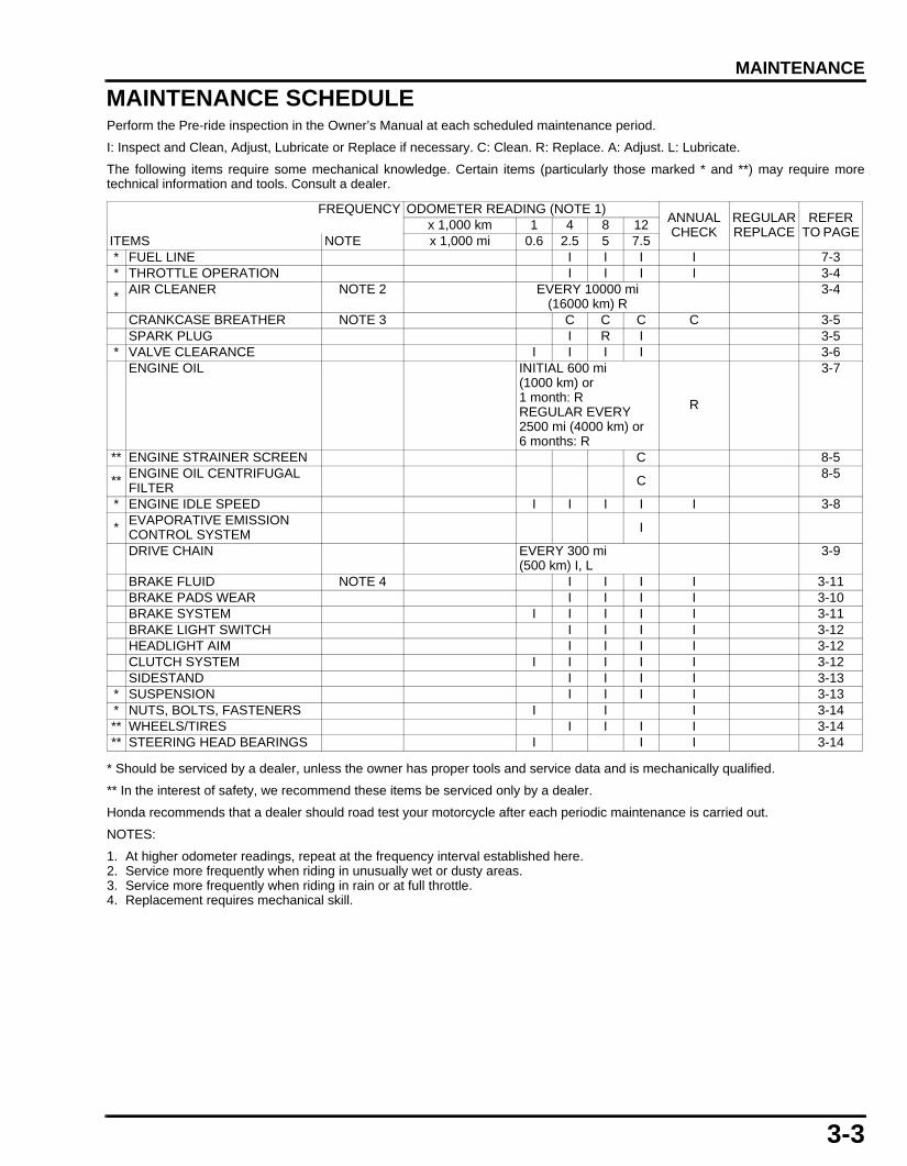
3-3
dummyheaddummyhead
MAINTENANCE
MAINTENANCE SCHEDULEPerform the Pre-ride inspection in the Owner’s Manual at each scheduled maintenance period.
I: Inspect and Clean, Adjust, Lubricate or Replace if necessary. C: Clean. R: Replace. A: Adjust. L: Lubricate.
The following items require some mechanical knowledge. Certain items (particularly those marked * and **) may require moretechnical information and tools. Consult a dealer.
* Should be serviced by a dealer, unless the owner has proper tools and service data and is mechanically qualified.
** In the interest of safety, we recommend these items be serviced only by a dealer.
Honda recommends that a dealer should road test your motorcycle after each periodic maintenance is carried out.
NOTES:
1. At higher odometer readings, repeat at the frequency interval established here.2. Service more frequently when riding in unusually wet or dusty areas.3. Service more frequently when riding in rain or at full throttle.4. Replacement requires mechanical skill.
FREQUENCY ODOMETER READING (NOTE 1)ANNUAL CHECK
REGULAR REPLACE
REFER TO PAGEx 1,000 km 1 4 8 12
ITEMS NOTE x 1,000 mi 0.6 2.5 5 7.5* FUEL LINE I I I I 7-3* THROTTLE OPERATION I I I I 3-4
*AIR CLEANER NOTE 2 EVERY 10000 mi
(16000 km) R3-4
CRANKCASE BREATHER NOTE 3 C C C C 3-5SPARK PLUG I R I 3-5
* VALVE CLEARANCE I I I I 3-6ENGINE OIL INITIAL 600 mi
(1000 km) or1 month: RREGULAR EVERY 2500 mi (4000 km) or6 months: R
R
3-7
** ENGINE STRAINER SCREEN C 8-5
**ENGINE OIL CENTRIFUGAL FILTER C
8-5
* ENGINE IDLE SPEED I I I I I 3-8
* EVAPORATIVE EMISSION CONTROL SYSTEM I
DRIVE CHAIN EVERY 300 mi(500 km) I, L
3-9
BRAKE FLUID NOTE 4 I I I I 3-11BRAKE PADS WEAR I I I I 3-10BRAKE SYSTEM I I I I I 3-11BRAKE LIGHT SWITCH I I I I 3-12HEADLIGHT AIM I I I I 3-12CLUTCH SYSTEM I I I I I 3-12SIDESTAND I I I I 3-13
* SUSPENSION I I I I 3-13* NUTS, BOLTS, FASTENERS I I I 3-14** WHEELS/TIRES I I I I 3-14** STEERING HEAD BEARINGS I I I 3-14
61K26000.book Page 3 Friday, July 12, 2013 3:51 PM

3-4
dummyheaddummyhead
MAINTENANCE
THROTTLE OPERATIONINSPECTIONCheck for any deterioration or damage to the throttlecable. Check the throttle grip for smooth operation.Check that the throttle opens and automatically closesin all steering positions.
If the throttle grip does not return properly, overhaul andlubricate the throttle grip housing.
If the throttle grip still does not return properly, replacethe throttle cable.
With the engine idling, turn the handlebar all the way tothe right and left to ensure that the idle speed does notchange. If idle speed increases, check the throttle gripfreeplay and throttle cable connection.
Measure the throttle grip freeplay at the grip flange.
If the freeplay is out of specification, adjust as follows.
ADJUSTMENTRemove the right shroud (page 2-4).
Remove the bolt [1] and throttle drum cover [2]
Loosen the lock nut [3], turn the adjuster [4] as requiredand tighten the lock nut while holding the adjuster.
Recheck the throttle operation and replace anydamaged parts, if necessary.
Installation is in the reverse order of removal.
AIR CLEANERREMOVAL/INSTALLATIONRemove the eight screws and air cleaner housing cover[1].
Remove screw and air cleaner element.
Discard the air cleaner element in accordance with themaintenance schedule (page 3-3).
Replace the element if it is excessively dirty ordamaged.
Install the removed parts in the reverse order ofremoval.
FREEPLAY:2 – 6 mm (0.08 - 0.24 in)
2 – 6 mm(0.08 - 0.24 in)
[1]
[2] [4]
[3]
Make sure the sealsare properly
positioned in thegrooves on the air
cleaner housingand cover.
TORQUE: Air cleaner housing cover screw1.1 N·m (0.1 kgf·m, 0.8 lbf·ft)
[1]
61K26000.book Page 4 Friday, July 12, 2013 3:51 PM

3-5
dummyheaddummyhead
MAINTENANCE
CRANKCASE BREATHER
Service more frequently when ridden in rain, at fullthrottle, or after the motorcycle is washed. Service if thedeposit level can be seen in the drain cap.
Remove the shroud (page 2-4).
Check the crankcase breather hose for deterioration,damage or leakage.
Install the removed parts in the reverse order ofremoval.
SPARK PLUGINSPECTIONDisconnect the spark plug cap.
Remove the spark plug [1].
Inspect or replace as described in the maintenanceschedule (page 3-3).
Clean the spark plug electrodes with a wire brush orspecial plug cleaner.Check the insulator for cracks or damage, and theelectrodes for wear, fouling or discoloration.
Measure the spark gap between the center and sideelectrodes with a feeler gauge.
If necessary, adjust the gap by bending the sideelectrode carefully.
Install and hand tighten the spark plug to the cylinderhead, then tighten the spark plug to the specifiedtorque.
Connect the spark plug cap.
Clean around thespark plug base
with compressed airbefore removing theplug and make sureno debris enters the
combustionchamber.
RECOMMENDED SPARK PLUG:STANDARD: CPR6EA-9 (NGK)
U20EPR9 (DENSO)
SPARK PLUG GAP: 0.8 – 0.9 mm (0.03 - 0.04 in)
TORQUE:16 N·m (1.6 kgf·m, 12 lbf·ft)
[1]
61K26000.book Page 5 Friday, July 12, 2013 3:51 PM

3-6
dummyheaddummyhead
MAINTENANCE
VALVE CLEARANCE
• Inspect and adjust the valve clearance while theengine is cold (below 35°C/95°F).
INSPECTIONRemove the bolts [1], valve adjusting hole caps and O-rings.
Remove the crankshaft hole cap and timing hole capfrom the left crankcase cover.
Rotate the crankshaft counterclockwise until the "T"mark [1] on the flywheel is aligned with the index notch[2] on the left crankcase cover.
Make sure that the piston is at TDC (Top Dead Center)on the compression stroke.
This position can be obtained by confirming that there isslack in the rocker arms. If there is no slack, turn thecrankshaft again until the correct position is obtained.
Check each valve clearance by inserting a feeler gauge[1] between the valve adjusting screw and valve stem.
ADJUSTMENTAdjust by loosening the lock nut and turning theadjusting screw until there is a slight drag on a feelergauge.
Apply engine oil to the lock nut.Hold the adjusting screw and tighten the lock nut to thespecified torque.
Recheck the valve clearance.
[1]
[2]
[1]
VALVE CLEARANCE: IN: 0.10 ± 0.02 mm (0.004 ± 0.001 in)EX: 0.17 ± 0.02 mm (0.007 ± 0.001 in)
TOOLS:Valve adjusting wrench 07708-0030400 or
07908-3290200 (U.S.A. only)
Lock nut wrench, 8 x 9 07708-0030100Commercially available in the U.S.A.
TORQUE:9.0 N·m (0.9 kgf·m, 6.6 lbf·ft)
61K26000.book Page 6 Friday, July 12, 2013 3:51 PM

3-7
dummyheaddummyhead
MAINTENANCE
Apply engine oil to a new crankshaft hole cap O-ringand timing hole cap O-ring, then install them to thecaps.Install and tighten the crankshaft hole cap and timinghole cap to the specified torque.
Install the new O-ring into grooves of the valve adjustinghole caps.
Install the valve adjusting hole caps to the cylinder headand tighten the bolts.
ENGINE OILOIL LEVEL INSPECTIONStart the engine and let it idle for 3 – 5 minutes.Stop the engine and wait 2 – 3 minutes.Hold the motorcycle in an upright position.Remove the oil filler cap/dipstick [1] and wipe oil fromthe dipstick with a clean cloth.Insert the oil filler cap/dipstick without screwing it in,remove it and check the oil level.
If the level is below or near the lower level line [2] on thedipstick, add the recommended oil to the upper levelline [3].
Install the oil filler cap/dipstick.
ENGINE OIL CHANGEWarm up the engine.Stop the engine, remove the oil filler cap/dipstick andwipe oil from the dipstick with a clean cloth.
Remove the drain bolt [1] and sealing washer [2].Drain oil completely.
Install the oil drain bolt with a new sealing washer andtighten it to the specified torque.
Fill the engine with recommended engine oil.
Check that the O-ring on the oil filler cap is in goodcondition, and replace it if necessary.Install the oil filler cap/dipstick.
Make sure there are no oil leaks.
Check the engine oil level (page 3-7).
TORQUE:Crankshaft hole cap 8.0 N·m (0.8 kgf·m, 5.9 lbf·ft)Timing hole cap 6.0 N·m (0.6 kgf·m, 4.4 lbf·ft)
RECOMMENDED ENGINE OIL:Pro Honda GN4 4-stroke oil (U.S.A. & Canada) or equivalent motorcycle oilAPI service classification: SG or higher (except oils labeled as energy conserving on the circular API service label)JASO T903 standard: MAViscosity: SAE 10W-30
TORQUE:24 N·m (2.4 kgf·m, 18 lbf·ft)
ENGINE OIL CAPACITY:0.9 liter (0.96 US Qt, 0.20 Imp gal) at draining1.1 liters (1.16 US Qt, 0.24 Imp gal) at disassembly
[2]
[1]
[3]
[1]
[2]
61K26000.book Page 7 Friday, July 12, 2013 3:51 PM

3-8
dummyheaddummyhead
MAINTENANCE
ENGINE IDLE SPEED
Failure to properly follow instructions can cause therough idling or the engine stall.
• Before checking the engine idle speed, inspectfollowing items.– No MIL blinking– Spark plug condition (page 3-5)– Air cleaner condition (page 3-4)
• Inspect and adjust the engine idle speed after allother engine maintenance items have beenperformed and are within specifications.
• Use a tachometer with graduations of 50 min-1 (rpm)or smaller that will accurately indicate a 50 min-1
(rpm) change.
Start the engine and let it idle 20 minutes.Check the engine idle speed.
If adjustment is necessary, turn the idle air screw [1] toobtain the specified engine idle speed.
• The idle air screw can be turned up to a 1/4 rotationper turn. Leave the engine idling for 10 seconds ormore to confirm the idle speed after adjustment.
• If the idling speed is still not in the specified engineidle speed, repeat the steps above.
ENGINE IDLE SPEED: 1,400 ± 100 min-1 (rpm)
IDLE AIR SCREW STANDARD OPENING:2 turns out from the fully seated position
[1]
61K26000.book Page 8 Friday, July 12, 2013 3:51 PM

3-9
dummyheaddummyhead
MAINTENANCE
DRIVE CHAIN
INSPECTIONDRIVE CHAIN SLACK INSPECTION
Support the motorcycle with its sidestand and shift thetransmission into neutral.
Measure the drive chain slack, on the chain run midwaybetween the sprockets.
Excessive chain slack, 50 mm or more, may damagethe frame.
CLEANING, LUBRICATION AND INSPECTION
Clean the chain with non-flammable or high flash pointsolvent [1] and wipe it dry.Be sure the chain has dried completely beforelubricating.Inspect the drive chain for possible damage or wear.Replace any chain that has damaged rollers, loosefitting links, or otherwise appears unserviceable.Installing a new chain on badly worn sprockets willcause the new chain to wear quickly.Inspect and replace the sprocket as necessary.
Lubricate the drive chain with #80 – 90 gear oil or drivechain lubricant. Wipe off any excess oil or chainlubricant.
Measure the distance between a span of 41 pins (40links) from pin center to pin center by holding so that alllinks are straight.
SPROCKET INSPECTION
Inspect the drive and driven sprocket teeth for wear ordamage, replace them if necessary.
Never use a new drive chain on worn sprockets.Both chain and sprockets must be in good condition, orthe new replacement chain will wear rapidly.
Never inspect and adjust the drive chain while the engine is running.
CHAIN SLACK: 30 – 40 mm (1.2 – 1.6 in)
DRIVE CHAIN LENGTH (41 pins/40 links)SERVICE LIMIT:518 mm (20.4 in)
Wipe and dry
Clean
[1]
DAMAGE
WEAR
NORMAL
61K26000.book Page 9 Friday, July 12, 2013 3:51 PM

3-10
dummyheaddummyhead
MAINTENANCE
ADJUSTMENTLoosen the rear axle nut [1] and both lock nuts [2].
Turn both drive chain adjusting nuts [3] until the correctdrive chain slack is obtained.
Make sure the same index lines of both adjusters arealigned with the hole ends on the swingarm.
Tighten the rear axle nut [1] to the specified torque.
Tighten the both drive chain adjusting nuts [3] and locknuts [2] securely.
Recheck the drive chain slack and free wheel rotation.
REMOVAL/INSTALLATIONSupport the motorcycle with its sidestand and shift thetransmission into neutral.
If the drive chain becomes extremely dirty, it should beremoved and cleaned prior to lubrication.
Remove the left crankcase rear cover.
Carefully remove the retaining clip [1] with pliers.Remove the master link [2] and link plate [3], anddisconnect the drive chain.Remove the drive chain.
Install in reverse order of removal.
Adjust the drive chain slack (page 3-10).
BRAKE PADS WEARCheck the brake pads for wear.Replace the brake pads if either pad is worn to the wearlimit groove [1].
For front brake pad replacement (page 17-7).
TORQUE:59 N·m (6.0 kgf·m, 44 lbf·ft)
[1][3]
[2]
[3]
[2]Drive
[1]
Always replace thebrake pads as a setto assure even disc
pressure.
[1]
61K26000.book Page 10 Friday, July 12, 2013 3:51 PM

3-11
dummyheaddummyhead
MAINTENANCE
BRAKE FLUID
Spilled fluid can damage painted, plastic or rubberparts. Place a rag over these parts whenever thesystem is serviced.
• Do not mix different types of fluid, as they are notcompatible with each other.
• Do not allow foreign material to enter the systemwhen filling the reservoir.
Check the front and rear brake fluid level.
If the level is near the lower level line [1], check thebrake pad wear (page 3-10).A low fluid level may be due to wear of the brake pads.If the brake pads are worn the caliper pistons arepushed out, and this accounts for a low reservoir level.If the brake pads are not worn and the fluid level is low,check the entire system for leaks (page 3-11).
BRAKE SYSTEMBRAKE INSPECTIONFirmly apply the brake lever and pedal check that no airhas entered the system.
If the lever feels soft or spongy when operated, bleedthe air from the system.
Inspect the brake hose [1] and fittings for deterioration,cracks and signs of leakage. Tighten any loose fittings.Replace hoses and fittings as required.
BRAKE PEDAL HEIGHT ADJUSTMENTMeasure the rear brake pedal freeplay (page 17-10).
[1]
[1]
61K26000.book Page 11 Friday, July 12, 2013 3:51 PM

3-12
dummyheaddummyhead
MAINTENANCE
BRAKE LIGHT SWITCH
• The front brake light switch cannot be adjusted. Ifthe front brake light switch actuation and brakeengagement are not synchronized, either replacethe switch unit or the malfunctioning parts of thesystem.
Check that the brake light comes on just prior to thebrake actually being engaged.
If the light fails to come on, adjust the switch [1] byturning the adjusting nut [2] so that the light comes on atthe proper time.
Recheck the brake light switch operation.
HEADLIGHT AIMPlace the motorcycle on a level surface.
Adjust the headlight beam vertically by loosening thebolt [1] and moving the headlight unit, then tighten thebolt.
CLUTCH SYSTEMMeasure the clutch lever freeplay at the end of theclutch lever.
Hold the switchbody and turn the
adjusting nut.Do not turn the
switch body whileturning the
adjusting nut.
[1]
[2]
Adjust the headlightbeam as specifiedby local laws and
regulations.
[1]
FREEPLAY:10 – 20 mm (0.4 - 0.8 in)
10 – 20 mm(0.4 - 0.8 in)
61K26000.book Page 12 Friday, July 12, 2013 3:51 PM

3-13
dummyheaddummyhead
MAINTENANCE
The adjuster maybe damaged if it ispositioned too far
out, leaving minimalthread
engagement.
Minor adjustment is made with the upper adjuster at theclutch lever.
Loosen the lock nut [1] and turn the adjuster [2].
Tighten the lock nut while holding the adjuster.
Recheck the clutch lever freeplay.
If the adjuster is threaded out near its limit and thecorrect freeplay cannot be obtained, turn the adjuster allthe way in and back out one turn, then perform theadjustment at major adjuster as follows.
Major adjustment is made with the lower adjust nut [1]at the clutch lifter lever.
Loosen the lock nut [2] and turn the adjust nut to adjustthe freeplay.Tighten the lock nut while holding the adjust nut.
If proper freeplay cannot be obtained, or the clutch slipsduring test ride, disassemble and inspect the clutch(page 11-9).
SIDESTANDSupport the motorcycle using a safety stand or hoist.
Check the sidestand springs for damage or loss oftension.Check the sidestand assembly for freedom ofmovement and lubricate the sidestand pivot ifnecessary.
SUSPENSIONFRONT SUSPENSION INSPECTIONCheck the action of the forks by operating the frontbrake and compressing the front suspension severaltimes.Check the entire assembly for signs of leaks, damageor loose fasteners.
Loose, worn ordamaged
suspension partsimpair motorcycle
stability and control.
Replace damaged components which cannot berepaired.
Tighten all nuts and bolts.
REAR SUSPENSION INSPECTIONCheck the action of the rear shock absorbers bycompressing them several times.Check the entire shock absorber assembly for signs ofleaks, damage or loose fasteners.Tighten all nuts and bolts.
Place the motorcycle on a level surface.
Check for worn swingarm bushings by grabbing the rearends of the swingarm and attempting to move theswingarm side to side.
Replace the swingarm bushings if any looseness isnoted.
[1]
[2]
[1]
[2]
61K26000.book Page 13 Friday, July 12, 2013 3:51 PM

3-14
dummyheaddummyhead
MAINTENANCE
NUTS, BOLTS, FASTENERSCheck that all chassis nuts and bolts are tightened totheir correct torque values (page 1-10).Check that all cotter pins, safety clips, hose clamps andcable stays are in place and properly secured.
WHEELS/TIRESSupport the motorcycle securely and raise the frontwheel off the ground.
Hold the fork leg and move the front wheel sidewayswith force to see if the wheel bearings are worn.
Check for worn wheel bearings by holding the swingarmand move the rear wheel sideways.
Replace the wheel bearings if any looseness is noted.
– Front wheel – Rear wheel
Check the tire pressure with a tire pressure gauge whenthe tires are cold.
Check the tires for cuts, embedded nails, or otherdamage.
Check the front and rear wheels for trueness.
Measure the tread depth at the center of the tires.Replace the tires when the tread depth reaches thefollowing limits.
STEERING HEAD BEARINGSSupport the motorcycle securely and raise the frontwheel off the ground.
Check that the handlebar moves freely from side toside. Make sure the control cables do not interfere withhandlebar rotation.
Check for steering stem bearings by grabbing the forklegs and attempting to move the front fork side to side.
If the handlebar moves unevenly, binds, or has verticalmovement, inspect the steering head bearings.
MINIMUM TIRE TREAD DEPTH: To indicator
61K26000.book Page 14 Friday, July 12, 2013 3:51 PM

4-1
4
dummytext
4. PGM-FI SYSTEM
SERVICE INFORMATION·····························4-2
SYSTEM LOCATION·····································4-3
SYSTEM DIAGRAM ······································4-4
PGM-FI SYMPTOM TROUBLESHOOTING···································4-5
PGM-FI TROUBLESHOOTING INFORMATION··············································4-6
DTC INDEX····················································4-9
DTC TROUBLESHOOTING ························4-10
MIL CIRCUIT INSPECTION ························ 4-22
TP SENSOR RESET PROCEDURE ··········· 4-23
ECM INITIALIZING PROCEDURE·············· 4-24
ALTITUDE SETTING ·································· 4-25
ECM····························································· 4-26
EOT SENSOR ············································· 4-27
BANK ANGLE SENSOR····························· 4-27
O2 SENSOR················································ 4-28
61K26000.book Page 1 Friday, July 12, 2013 3:51 PM

4-2
dummyheaddummyhead
PGM-FI SYSTEMPGM-FI SYSTEM
SERVICE INFORMATIONGENERAL • A faulty PGM-FI system is often related to poorly connected or corroded connectors. Check those connections before
proceeding. • Use a digital tester for PGM-FI system inspection. • The following color codes are used throughout this section.
SPECIFICATIONS
TORQUE VALUES
PGM-FI SYSTEM
TOOLS
Bu = Blue G = Green Lb = Light Blue O = Orange R = Red Y = YellowBl = Black Gr = Gray Lg = Light Green P = Pink W = White Br = Brown
ITEM SPECIFICATIONSEngine idle speed 1,400 ± 100 min-1 (rpm)IAT sensor resistance (40°C/104°F) 21.2 – 16.4 kΩEOT sensor resistance (20°C/68°F) 2.5 – 2.8 kΩ
(100°C/212°F) 0.21 – 0.22 kΩFuel injector resistance (20°C/68°F) 11 – 13 Ω
ITEM Q'TYTHREAD TORQUE
REMARKSDIA. (mm) N·m (kgf·m, lbf·ft)
Bank angle sensor mounting nut 2 6 10 (1.0, 7)Injector joint mounting bolt 2 5 12 (1.2, 9)EOT sensor 1 10 14.5 (1.5, 11) Apply engine oil to the
threads and seating surface.
O2 sensor 1 12 24.5 (2.5, 18)
SCS Service Connector070PZ-ZY30100
Pin Prove Male (2 pack)07ZAJ-RDJA110
61K26000.book Page 2 Friday, July 12, 2013 3:51 PM

4-3
dummyheaddummyhead
PGM-FI SYSTEM
SYSTEM LOCATION
EOT SENSOR
ECM
FUEL PUMP UNIT
FUEL INJECTOR
TP SENSOR
DLC O2 SENSORVS SENSOR
BANK ANGLE SENSOR
CKP SENSOR
IAT SENSOR
61K26000.book Page 3 Friday, July 12, 2013 3:51 PM

4-4
dummyheaddummyhead
PGM-FI SYSTEM
SYSTEM DIAGRAM
Y
G/O
Y/R
R
Y/Bu
Bl/OBl/O
P/G
G/O
W/Bu
G/O
Bu
Y
G/Bl
W
W
Bu/Y
W/Y
Br
Bl/Y
Y/G
W/Bu
GG G/Bl
Bl/Bu
Bl/Bu
R/Bu
R/Y
Bl
Bl
P/G
R
G
G
G
G
R
R
Y/R
G
G
R/W G/R
G/R G/R
G/R
G/W G/W
Lg/R
Lg/RLg/R
R/Y
R/YR/Y Bl/R
Bl/W Bl/W
Bl/W
Bl/W
Bl/W
Bl/W
Bl/WBl/W
Bl/W
Bl/Bu
Bl/Bu
Bl/Y
BlYBuGRW
: Black: Yellow: Blue: Green: Red: White
BrOLgPGr
: Brown: Orange: Light green: Pink: Gray
Bl
Y/Bl Bl/W
Y/O Bl/W
TPSENSOR
(8)
DLC
ALTERNATORCKPSENSOR
MIL
1
23
12
11
33
22
STARTERSWITCH
10AFI FUSE
NEUTRAL INDICATOR
BATTERY
15AMAIN FUSE
SCSCONNECTOR
EOTSENSOR
(7)
O2
SENSOR
(21)
BANK ANGLESENSOR
(54)
FUEL INJECTOR
ENGINE STOPSWITCH
(12)
SPARKPLUG
IGNITIONCOIL
COMBINATION METER
FUEL PUMP
L blinks( ) : Number of MIL blinks
: The engine does not start if there is mulfunction
ECM 33P CONNECTOR
ECM side of the male terminals
NEUTRALSWITCH
SIDESTANDSWITCH
IGNITIONSWITCH
STARTERRELAY
STARTERMOTOR
10ADC FUSE
THL5
SG14
VCC6
TO24
3 O2
SG231
IATSENSOR
(9)TA14
SG332
29 NLSW
25 SSTAND
15 SCS
30 K-LINE
PCM23
PCP12
1IGP
8FFL
16INJ
26BA
11IGPLS
28TACHO
22FI-IND
109 PG2PG1 2LG
(33)ECM
REGULATOR/RECTIFIER
CLUTCHSWITCH
19
20
PCS
SOL V
EVAP PURGE CONTROL SOLENOID VALVE
FAST IDLE SOLENOID VALVE
61K26000.book Page 4 Friday, July 12, 2013 3:51 PM

4-5
dummyheaddummyhead
PGM-FI SYSTEM
PGM-FI SYMPTOM TROUBLESHOOTINGWhen the motorcycle has one of these symptoms, check the MIL blinking, refer to the DTC index (page 4-9) and begin theappropriate troubleshooting procedure. If there are no MIL blinking stored in the ECM memory, do the diagnostic procedure for thesymptom, in sequence listed below, until you find cause.
Symptom Diagnosis procedure Also check forEngine cranks but won’t start(No DTC and MIL blinking)
1. ECM initializing (page 4-24).2. Check the spark plug condition (page 3-5).3. Inspect the ignition system (page 5-5).4. Check the cylinder compression
(page 9-6).5. Check the idle air port/screw (page 7-8).6. Check the fuel supply system (page 7-3).
• No fuel to fuel injector– Clogged fuel filter– Clogged fuel filler cap breather hole– Pinched or clogged fuel feed hose– Faulty fuel pump– Faulty fuel pump circuits
• Intake air leak • Contaminated/deteriorated fuel • Faulty fuel injector
Engine cranks but won’t start(No fuel pump operation sound when turning the ignition ON)
1. ECM power/ground line malfunction (page 4-26).
2. Check the fuel supply system (page 7-3).
• Faulty main fuse 15 A • Faulty sub fuse 10 A (FI,DC)
Engine stalls, hard to start, rough idling
1. ECM initializing (page 4-24).2. Check the engine idle speed (page 3-8).3. Check the idle air port/screw (page 7-8).4. Inspect the fuel supply system (page 7-3).5. Inspect the battery charging system (page
18-5).6. Inspect the ignition system (page 5-5).
• Restricted fuel feed hose • Clogged fuel filler cap breather hole • Contaminated/deteriorated fuel • Intake air leak
Backfiring or misfiring during acceleration
Inspect the ignition system (page 5-5).
Poor performance (driveability) and poor fuel economy
1. Check the fuel supply system (page 7-3).2. Check the air cleaner element (page 3-4).3. Inspect the ignition system (page 5-5).
• Pinched or clogged fuel feed hose • Faulty pressure regulator (fuel pump) • Faulty fuel injector
Engine idle speed is below specifications
1. Check the engine idle speed (page 3-8).2. Check the idle air port/screw (page 7-8).3. Inspect the ignition system (page 5-5).4. Check the fuel supply system (page 7-3).
Engine idle speed is above specifications
1. Check the engine idle speed (page 3-8).2. Check the idle air port/screw (page 7-8).3. Inspect the ignition system (page 5-5).4. Check the throttle operation and freeplay
(page 3-4).5. Check the air cleaner element (page 3-4).
• Intake air leak • Engine top-end problem
MIL stays ON or MIL never comes ON at all (Engine operates normally)
Inspect the MIL circuit (page 4-22).
MIL stays ON(Engine operates normally and No DTC set)
1. Inspect the MIL circuit (page 4-22).2. Inspect the DLC circuit.
61K26000.book Page 5 Friday, July 12, 2013 3:51 PM

4-6
dummyheaddummyhead
PGM-FI SYSTEM
PGM-FI TROUBLESHOOTING INFORMATIONGENERAL TROUBLESHOOTINGINTERMITTENT FAILURE
The term "intermittent failure" means a system may have had a failure, but it checks OK now. If the MIL does not come on, checkfor poor contact or loose pins at all connectors related to the circuit. If the MIL was on, but then went out, the original problem maybe intermittent.
OPENS AND SHORTS
"Opens" and "Shorts" are common electrical terms. An open is a break in a wire or at a connection. A short is an accidentalconnection of a wire to ground or to another wire. In simple electronics, this usually means something will not work at all. WithECMs this can sometimes mean something works, but not the way it’s supposed to.
If the Engine has problem, and MIL comes on
Refer to DTC READOUT (page 4-7).
If the Engine has problem, but MIL does not stay on or blink
Refer to the SYMPTOM TROUBLESHOOTING (page 4-5).
SYSTEM DESCRIPTIONSELF-DIAGNOSIS SYSTEM
The PGM-FI system is equipped with the self-diagnostic system. When any abnormality occurs in the system, the ECM turns on theMIL (Malfunction Indicator Lamp) and stores a DTC in its erasable memory.
CURRENT DTC/STORED DTC
The DTC is indicated in two ways according to the failure status.
• In case the ECM detects the problem at present, the MIL will start blinking as its DTC. It is possible to read out the MIL blinkpattern as the current DTC.
• In case the ECM does not detect any problem at present but has a problem stored in its memory, the MIL will not blink. If it isnecessary to retrieve the past problem, read out the stored DTC by following the DTC readout procedure (page 4-7).
MIL BLINK PATTERN
• DTC can be read by the MIL blink pattern. • In case the ECM does not detect any problem at present, when the ignition switch is turned "ON", the MIL will stay on for a few
seconds, then go off. • In case the ECM detects the problem at present, when the ignition switch is turned "ON", the MIL will stay on for a few seconds
and go off, then the MIL blinks as its DTC. • The MIL has two types of blinks, a long blink and short blink. The long blinking lasts for 1.3 seconds, the short blinking lasts for
0.3 seconds. One long blink is the equivalent to ten short blinks. For example, when two long blinks are followed by five shortblinks, the MIL is 25 (two long blinks = 20 blinks, plus five short blinks).
• The MIL will start blinking when the ignition switch is "ON" or engine revs are below 1800 min-1 (rpm). In any other conditions,the MIL will illuminate and stay on.
MIL CIRCUIT CHECK
If the MIL does not come on or stays on when the ignition switch is turned "ON", inspect the MIL circuit (page 4-22).
FAIL-SAFE FUNCTION
The PGM-FI system is provided with a fail-safe function to secure a minimum running capability even when there is trouble in thesystem. When any abnormality is detected by the self-diagnosis function, running capability is maintained by pre-programed valuein the simulated program map. When any abnormality is detected in the fuel injector and/or crankshaft position (CKP) sensor, thefail-safe function stops the engine to protect it from damage.
61K26000.book Page 6 Friday, July 12, 2013 3:51 PM

4-7
dummyheaddummyhead
PGM-FI SYSTEM
MCS INFORMATION • The MCS can readout the DTC, freeze data, current data and other ECM condition.
How to connect the MCS
Turn the ignition switch "OFF".
Remove the seat (page 2-3).
Remove the connector cover from the DLC [1] and connect the MCS to theDLC.
• Freeze data indicates the engine conditions when the first malfunctionwas detected.
DTC READOUTCURRENT DTC
Place the motorcycle on a level surface and check the MIL.
• When the ignition switch is turned "ON", the MIL will stay on for a few seconds, then go off.
If the MIL stays on or blinks, note how many times the MIL blinks and determine the cause of the problem.
If the MIL does not blink, the system is normal at present. If you wish to read the stored DTC, perform the following:
TO READ THE STORED DTC
Turn the ignition switch "OFF".
Remove the seat (page 2-3).
Remove the connector cover from the DLC [1] and short the DLC terminalsusing the special tool.
If the ECM has no stored DTC, the MIL will illuminate, when you turn the ignition switch "ON".
If the ECM has stored DTC, the MIL will illuminate 0.3 seconds and go off, then start blinking as its DTC when you turn the ignitionswitch "ON".
Note how many times the MIL blinks, and determine the cause of the problem.
[1]
TOOL:[2] SCS connector 070PZ-ZY30100CONNECTION: Blue – Green/black
[2]
[1]
61K26000.book Page 7 Friday, July 12, 2013 3:51 PM

4-8
dummyheaddummyhead
PGM-FI SYSTEM
ERASING DTCConnect the MCS to the DLC.
Erase the DTC with the MCS while the engine is stopped.
To erase the DTC without MCS, refer to the following procedure.
How to erase the DTC with SCS service connector
1. Turn the ignition switch "OFF".
2. Remove the front body cover (page 2-6).
3. Remove the connector cover from the DLC [1] and short the DLCterminals using the special tool.
4. Turn the ignition switch "ON".
5. Disconnect the SCS connector [1] from the DLC [2].
Connect the DLC short connector to the DLC again while the MIL staysON about 5 seconds (reset receiving pattern).
6. The stored DTC is erased if the MIL goes off and starts blinking(successful pattern).
• The DLC must be jumped while the MIL lights. If not, the MIL will go off and stay on (unsuccessful pattern). In that case, turn theignition switch to "OFF" and try again from step 3.
• Note that the self-diagnostic memory cannot be erased if the ignition switch is turned “OFF” before the MIL starts blinking.
CIRCUIT INSPECTIONINSPECTION AT ECM AND SENSOR UNIT CONNECTOR
• Always clean around and keep any foreign material away from the connector before disconnecting it. • A faulty PGM-FI system is often related to poorly connected or corroded connections. Check those connections before
proceeding. • When testing at connector (wire harness side) terminal, always use the test probe [1]. Insert the test probe into the connector
terminal, then connect the digital multimeter probe to the test probe.
TOOL:[2] SCS connector 070PZ-ZY30100CONNECTION: Blue – Green/black
[2]
[1]
TOOL:[1] Test probe 07ZAJ-RDJA110
[1]
61K26000.book Page 8 Friday, July 12, 2013 3:51 PM

4-9
dummyheaddummyhead
PGM-FI SYSTEM
DTC INDEX
• If not using the MCS, perform all inspections according to the relevant main code.
DTC Function Failure Symptom/Fail-safe function Refer to
7-1 EOT sensor circuit low voltage (less than 0.07 V) • EOT sensor or its circuit malfunction
• Hard start at a low temperature • Pre-program value: 100°C/212°F
4-10
7-2EOT sensor circuit high voltage (more than 4.93 V) • Loose or poor contact of the EOT sensor connector • EOT sensor or its circuit malfunction
• Hard start at a low temperature • Pre-program value: 100°C/212°F 4-11
8-1TP sensor circuit low voltage (less than 0.3 V) • Loose or poor contact of the TP sensor connector • TP sensor or its circuit malfunction
• Poor engine acceleration • Pre-program value: 0° 4-12
8-2TP sensor circuit high voltage (more than 4.93 V) • TP sensor or its circuit malfunction
• Poor engine acceleration • Pre-program value: 0° 4-14
9-1IAT sensor circuit low voltage (more than 0.07 V) • IAT sensor or its circuit malfunction
• Engine operates normally • Pre-program value: 35°C/95°F 4-15
9-2IAT sensor circuit high voltage (less than 4.93 V) • Loose or poor contact of the IAT sensor connector • IAT sensor or its circuit malfunction
• Engine operates normally • Pre-program value: 35°C/95°F 4-16
12-1Fuel injector malfunction • Loose or poor contact of the fuel injector connector • Fuel injector or its circuit malfunction
• Engine does not start • Fuel injector, fuel pump and
ignition coil shut down4-17
21-1O2 sensor malfunction • Loose or poor contact of the O2 sensor connector • O2 sensor or its circuit malfunction
• Engine operates normally4-18
33-2EEPROM malfunction • Engine stalls, hard to start, rough
idling 4-19
54-1
Bank angle sensor circuit low voltage (less than 0.02 V) • Loose or poor contact of the bank angle sensor
connector • Bank angle sensor or its circuit malfunction
• Engine operates normally • Bank angle sensor does not
operate.(The engine keeps running when the vehicle falls.)
4-20
54-2
Bank angle sensor circuit high voltage (more than 4.98 V) • Loose or poor contact of the bank angle sensor
connector • Bank angle sensor or its circuit malfunction
• Engine operates normally • Bank angle sensor does not
operate.(The engine keeps running when the vehicle falls.)
4-21
61K26000.book Page 9 Friday, July 12, 2013 3:51 PM

4-10
dummyheaddummyhead
PGM-FI SYSTEM
DTC TROUBLESHOOTINGDTC 7 (EOT SENSOR) • Before starting the inspection, check for loose or poor contact on the EOT sensor 2P connector and ECM
33P (Black) connector and recheck the MIL blinking.
Probable cause • Open or short circuit in Yellow/blue wire between the
EOT sensor and ECM • Open circuit in Green/Orange wire between the EOT
sensor and ECM • Faulty EOT sensor • Faulty ECM
DTC 7-1 (EOT SENSOR LOW VOLTAGE)
1. EOT Sensor System Inspection
Turn the ignition switch "ON" and engine stop switch" ".Check the EOT sensor withe the MCS.
Is about 0 V indicated?
YES – GO TO STEP 2.
NO – Intermittent failure
2. EOT Sensor Inspection
Turn the ignition switch "OFF".Disconnect the EOT sensor 2P connector.Turn the ignition switch "ON" and engine stop switch" ".Check the EOT sensor with the MCS.
Is about 0 V indicated?
YES – GO TO STEP 4.
NO – GO TO STEP 3.
3. EOT Sensor Resistance Inspection
Turn the ignition switch "OFF".Measure the resistance at the sensor side of theEOT sensor 2p connector terminals.
Is the resistance within 2.5 – 2.8 kΩ?
YES – Replace the ECM with a known good one,and recheck.
NO – Faulty EOT sensor
Y/Bu
G/O
5 V
ECM
EOT SENSOR
CONNECTION: Yellow/blue – Green/orangeSTANDARD: 2.5 – 2.8 kΩ (20°C/68°F)
G/O Y/Bu
61K26000.book Page 10 Friday, July 12, 2013 3:51 PM

4-11
dummyheaddummyhead
PGM-FI SYSTEM
4. EOT Sensor Output Line Short CircuitInspection
Turn the ignition switch "OFF".Check the continuity between the EOT sensor 2pconnector of the wire harness side and ground.
Is there continuity?
YES – Short circuit Green/orange wire
NO – Replace the ECM with a known good one,and recheck.
DTC 7-2 (EOT SENSOR HIGH VOLTAGE)
1. EOT sensor System Inspection
Turn the ignition switch ON and engine stop switch" ".
Check the EOT sensor with the MCS.
Is about 5 V indicated?
YES – GO TO STEP 2.
NO – Intermittent failure
2. EOT sensor Inspection
Turn the ignition switch "OFF".Disconnect the EOT sensor 2P connector [1].
Connect the EOT sensor 2P connector terminals atthe wire side with a jumper wire.
Turn the ignition switch "ON" and engine stop switch" ".
Check the EOT sensor with the MCS.
Is about 0 V indicated?
YES – Faulty EOT sensor
NO – GO TO STEP 3.
3. EOT sensor Output Line Circuit Inspection
Turn the ignition switch "OFF".Remove the jumper wire.Disconnect the ECM 33P connectors.
Check for continuity between the EOT sensor 2Pconnector and ECM 33P connectors at the wireharness side.
Is there continuity?
YES – Replace the ECM with a known good one,and recheck
NO – • Open circuit in Yellow/blue wire • Open circuit in Green/orange wire
CONNECTION: Yellow/blue – Ground
Y/Bu
CONNECTION: Yellow/blue – Green/orange
G/OY/Bu
CONNECTION: 24 – Yellow/blue31 – Green/orange
TOOL:Pin Probe Male (2 pack) 07ZAJ-RDJA110
G/O
Y/Bu
61K26000.book Page 11 Friday, July 12, 2013 3:51 PM

4-12
dummyheaddummyhead
PGM-FI SYSTEM
DTC 8 BLINKS (TP SENSOR) • Before starting the inspection, check for loose or poor contact on the TP sensor 3P connector and ECM 33P
(Black) connector and recheck the MIL blinking.
Probable cause • Open circuit in Yellow/red wire between the TP
sensor and ECM • Open or short circuit in Yellow wire between the TP
sensor and ECM • Open circuit in Green/orange wire between the TP
sensor and ECM • Faulty TP sensor • Faulty ECM
DTC 8-1 (TP SENSOR LOW VOLTAGE)
1. TP Sensor System Inspection
Turn the ignition switch "ON" and engine stop switch" ".Check the TP sensor withe the MCS when thethrottle is fully closed.
Is about 0 V indicated?
YES – GO TO STEP 3.
NO – GO TO STEP 2.
2. TP Sensor Inspection
Check that the TP sensor voltage increases?continuously when moving the throttle from fully?closed to fully opened using the data list menu ofthe? MCS.
Does the voltage increase continuously?
YES – Intermittent failure
NO – Faulty TP sensor
Y/R
G/O
5 V
ECM
TP SENSOR
Y
61K26000.book Page 12 Friday, July 12, 2013 3:51 PM

4-13
dummyheaddummyhead
PGM-FI SYSTEM
3. TP Sensor Resistance Inspection
Turn the ignition switch "OFF".Disconnect the TP sensor 3P connector (page 7-8).Measure the resistance at the sensor side of the TPsensor 3P connector terminals.
Is the resistance within 0.5 – 1.5 kΩ (20°C/68°F)?
YES – GO TO STEP 4.
NO – Faulty TP sensor
4. TP Sensor Output Line Open Circuit Inspection
Turn the ignition switch OFF.Disconnect the ECM 33P (Gray) connector.Check for continuity between the TP sensor 3Pconnector and ECM 33P (Gray) connector at thewire harness side.
Is there continuity?
YES – GO TO STEP 5.
NO – Open circuit in yellow wire
5. TP Sensor Output Line Short Circuit Inspection
Check for continuity between the TP sensor 3Pconnector at the wire side and ground.
Is there continuity?
YES – Short circuit in yellow wire
NO – GO TO STEP 6.
6. TP Sensor Power Input Voltage Inspection
Turn the ignition switch "OFF".Disconnect the TP sensor 3P connector (page 7-8).
Turn the ignition switch "ON" and engine stop switch" ".Measure the voltage at the TP sensor 3P connectorof the wire harness side.
Is the voltage within 4.75 – 5.25 V?
YES – Faulty TP sensor
NO – GO TO STEP 7.
CONNECTION: Yellow – Green/orange
YY/R
CONNECTION: 5 – Yellow Y
CONNECTION: Yellow – Ground
Y
CONNECTION: Yellow/red (+) – Green/orange (–)STANDARD: 4.75 – 5.25 V
Y/RG/O
[1]
61K26000.book Page 13 Friday, July 12, 2013 3:51 PM

4-14
dummyheaddummyhead
PGM-FI SYSTEM
7. TP Sensor Input Line Circuit Inspection
Turn the ignition switch "OFF".Disconnect the ECM 33P (Black) connector (page4-26).
Check for continuity between the TP sensor 3Pconnector and ECM 33P (Black) connector of thewire harness side.
Are there continuity?
YES – Replace the ECM with a known good one,and recheck.
NO – • Open circuit in Yellow/red wire • Open circuit in Green/orange wire
DTC 8-2 (TP SENSOR HIGH VOLTAGE)
1. TP Sensor System Inspection
Turn the ignition switch "ON" and engine stop switch" ".Check the TP sensor withe the MCS when thethrottle is fully closed.
Is about 0 V indicated?
YES – GO TO STEP 3.
NO – GO TO STEP 2.
2. TP sensor Inspection
Check that the TP sensor voltage increasescontinuously when moving the throttle from fullyclosed to fully opened using the data list menu of theMCS.
Does the voltage increase continuously?
YES – Intermittent failure
NO – Faulty TP sensor
3. TP Sensor Resistance Inspection
Turn the ignition switch "OFF".Disconnect the TP sensor 3P connector (page 7-8).Measure the resistance at the sensor side of the TPsensor 3P connector terminals.
Is the resistance within 0.5 - 1.5 kΩ (20°C/68°F)?
YES – GO TO STEP 4.
NO – Faulty TP sensor
TOOL:Test probe 07ZAJ-RDJA110
CONNECTION: 6 - Yellow/red4 - Green/orange
Y/R
G/O
CONNECTION: Yellow/red – Green/orange
Y/R G/O
61K26000.book Page 14 Friday, July 12, 2013 3:51 PM

4-15
dummyheaddummyhead
PGM-FI SYSTEM
4. TP Sensor Input Voltage Inspection
Turn the ignition switch ON and engine stop switch" ".
Measure the voltage at the wire side of the TPsensor 3P connector terminals.
Is the voltage within 4.75 – 5.25 V?
YES – Replace the ECM with a known good one,and recheck
NO – Open circuit in Yellow/red or Green/orangewire
DTC 9 (IAT SENSOR) • Before starting the inspection, check for loose or poor contact on the IAT sensor 2P (Black) connector and
ECM 33P connectors, then recheck the DTC.
Probable cause • Open or short circuit in Gray/blue wire between the
IAT sensor and ECM • Open circuit in Light green/red wire between the IAT
sensor and ECM • Faulty IAT sensor • Faulty ECM
DTC 9-1 (IAT SENSOR LOW VOLTAGE)
1. IAT Sensor System Inspection
Turn the ignition switch ON and engine stop switch" ".
Check the IAT sensor with the MCS.
Is about 0 V indicated?
YES – GO TO STEP 2.
NO – Intermittent failure
2. IAT Sensor Inspection
Turn the ignition switch OFF.Disconnect the IAT sensor 2P (Black) connector.
Turn the ignition switch ON and engine stop switch" ".Check the IAT sensor with the MCS.
Is about 0 V indicated?
YES – GO TO STEP 3.
NO – Faulty IAT sensor
Connection: Yellow/red – Green/orangeY/RG/O
W/Bu
G/O
5 V
ECMIAT SENSOR
61K26000.book Page 15 Friday, July 12, 2013 3:51 PM

4-16
dummyheaddummyhead
PGM-FI SYSTEM
3. IAT Sensor Output Line Short Circuit Inspection
Turn the ignition switch OFF.
Check for continuity between the IAT sensor 2Pconnector at the wire harness side and ground.
Is there continuity?
YES – Short circuit in White/blue wire
NO – Replace the ECM with a known good one,and recheck
DTC 9-2 (IAT SENSOR HIGH VOLTAGE)
1. IAT Sensor System Inspection
Turn the ignition switch ON and engine stop switch" ".
Check the IAT sensor with the MCS.
Is about 5 V indicated?
YES – GO TO STEP 2.
NO – Intermittent failure
2. IAT Sensor Inspection
Turn the ignition switch OFF.Disconnect the IAT sensor 2P connector.
Connect the IAT sensor 2P connector terminals atthe wire harness side with a jumper wire.
Turn the ignition switch ON and engine stop switch" ".
Check the IAT sensor with the MCS.
Is about 0 V indicated?
YES – Faulty IAT sensor
NO – GO TO STEP 3.
3. IAT Sensor Line Inspection
Turn the ignition switch OFF.Remove the jumper wire.Disconnect the ECM 33P connectors.
Check for continuity between the IAT sensor 2Pconnector and ECM 33P and connectors at the wireharness side.
Is there continuity?
YES – Replace the ECM with a known good one,and recheck
NO – • Open circuit in White/blue wire • Open circuit in Green/orange wire
Connection: White/blue – GroundW/Bu
Connection: White/blue – Green/orange
G/O W/Bu
Connection: 14 – White/blue32 – Green/orange
TOOL:Pin Probe Male (2 pack) 07ZAJ-RDJA110
W/Bu
G/O
61K26000.book Page 16 Friday, July 12, 2013 3:51 PM
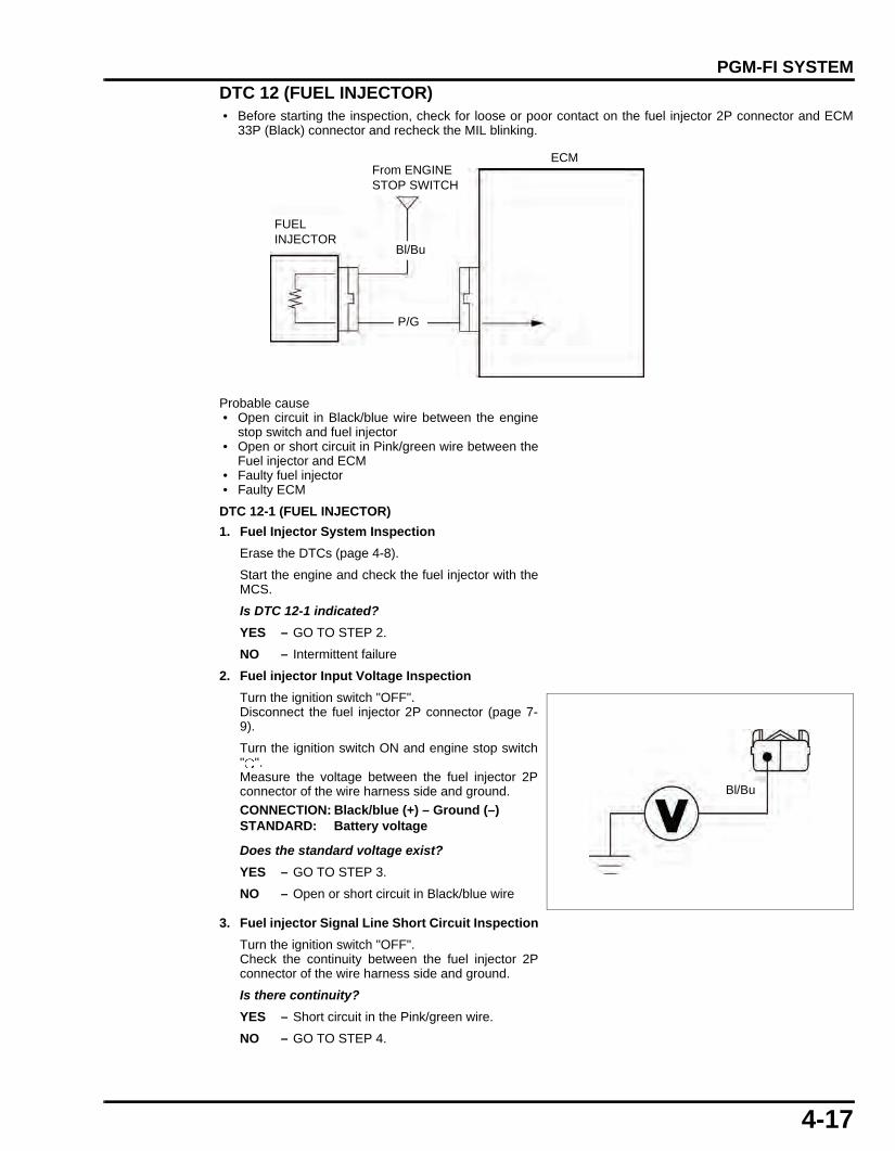
4-17
dummyheaddummyhead
PGM-FI SYSTEM
DTC 12 (FUEL INJECTOR) • Before starting the inspection, check for loose or poor contact on the fuel injector 2P connector and ECM
33P (Black) connector and recheck the MIL blinking.
Probable cause • Open circuit in Black/blue wire between the engine
stop switch and fuel injector • Open or short circuit in Pink/green wire between the
Fuel injector and ECM • Faulty fuel injector • Faulty ECM
DTC 12-1 (FUEL INJECTOR)
1. Fuel Injector System Inspection
Erase the DTCs (page 4-8).
Start the engine and check the fuel injector with theMCS.
Is DTC 12-1 indicated?
YES – GO TO STEP 2.
NO – Intermittent failure
2. Fuel injector Input Voltage Inspection
Turn the ignition switch "OFF".Disconnect the fuel injector 2P connector (page 7-9).
Turn the ignition switch ON and engine stop switch" ".Measure the voltage between the fuel injector 2Pconnector of the wire harness side and ground.
Does the standard voltage exist?
YES – GO TO STEP 3.
NO – Open or short circuit in Black/blue wire
3. Fuel injector Signal Line Short Circuit Inspection
Turn the ignition switch "OFF".Check the continuity between the fuel injector 2Pconnector of the wire harness side and ground.
Is there continuity?
YES – Short circuit in the Pink/green wire.
NO – GO TO STEP 4.
Bl/Bu
ECM
FUEL INJECTOR
From ENGINE STOP SWITCH
P/G
CONNECTION: Black/blue (+) – Ground (–)STANDARD: Battery voltage
Bl/Bu
61K26000.book Page 17 Friday, July 12, 2013 3:51 PM

4-18
dummyheaddummyhead
PGM-FI SYSTEM
4. Fuel injector Resistance Inspection
Measure the resistance between the terminals ofthe fuel injector side 2P connector.
Is the resistance within 11 - 13 Ω (20°C/68°F)?
YES – GO TO STEP 5.
NO – Faulty fuel injector
5. Fuel injector Signal Line Open Circuit Inspection
Turn the ignition switch "OFF".Disconnect the ECM 33P (Black) connector (page4-26).
Check the continuity between the ECM 33Pconnector and injector 2P connector of the wireharness side.
Are the above inspections normal?
YES – Replace the ECM with a known good one,and recheck.
NO – Open circuit in Pink/green wire
DTC 21 (O2 SENSOR) • Before starting the inspection, check for loose or poor contact on the O2 sensor cap, O2 sensor 1P connector
and ECM 33P (Black) connector and recheck the MIL blinking.
Probable cause • Open or short circuit in Black/orange wire between
the O2 sensor and ECM • Faulty O2 sensor • Faulty ECM
STANDARD: 11 - 13 Ω (20°C/68°F)
Bl/BuP/G
TOOL:Pin Probe Male (2 pack) 07ZAJ-RDJA110
CONNECTION: 16 – Pink/GreenSTANDARD: Continuity
P/G
ECM
O2 SENSOR
Bl/O Bl/O
61K26000.book Page 18 Friday, July 12, 2013 3:51 PM

4-19
dummyheaddummyhead
PGM-FI SYSTEM
DTC 21-1 (O2 SENSOR)
1. O2 Sensor Open Circuit Inspection
Turn the ignition switch "OFF".Disconnect the ECM 33P (Black) connector (page4-26) and O2 sensor cap.
Check the continuity between the terminal of the O2
sensor cap and ECM 33P connector of the wireharness side.
Is there continuity?
YES – GO TO STEP 2.
NO – Open circuit in Black/orange wire
2. O2 Sensor Short Circuit Inspection
Turn the ignition switch "OFF".Disconnect the ECM 33P connector (page 4-26)and O2 sensor cap.
Check the continuity between the terminal of the O2
sensor cap and ground.
Is there continuity?
YES – Short circuit in Black/orange wire
NO – GO TO STEP 3.
3. O2 Sensor Inspection
Replace the O2 sensor with a known good one(page 4-28).Perform the ECM initializing procedure (page 4-24).Erase the self diagnosis memory data from the ECM(page 4-8).
Start the engine and warm it up.Test-ride the motorcycle and recheck the O2 sensorwith the MCS.
Does the DTC21-1 indicated?
YES – Replace the ECM with a known good one,and recheck.
NO – Faulty original O2 sensor
DTC 33 BLINKS (EEPROM)DTC 33-2 (EEPROM)
1. Recheck MIL
Erase the DTC (page 4-8).Perform the ECM initializing procedure (page 4-24).
Is DTC 33-2 indicated?
YES – Replace the ECM with a known good one,and recheck.
NO – Intermittent failure
CONNECTION: O2 sensor cap terminal – 3
CONNECTION: O2 sensor cap terminal – Ground
61K26000.book Page 19 Friday, July 12, 2013 3:51 PM

4-20
dummyheaddummyhead
PGM-FI SYSTEM
DTC 54 BLINKS (BANK ANGLE SENSOR)
Before starting the inspection, check for loose or poor contact on the bank angle sensor 2P connector andrecheck the MIL blinking.
Probable cause • Open circuit in Black/blue wire between the engine
stop switch and bank angle sensor • Open or short circuit in Red/blue wire between the
bank angle sensor and ECM • Faulty bank angle sensor • Faulty ECM
DTC 54-1 (BANK ANGLE SENSOR LOW VOLTAGE)
1. BANK ANGLE SENSOR SYSTEM INSPECTION
Erase the DTCs (page 4-8).Check the bank angle sensor with the HDS pockettester.
Is about 0 V indicated?
YES – GO TO STEP 2.
NO – Intermittent failure
2. BANK ANGLE SENSOR POWER INPUT LINEOPEN INSPECTION
Turn the ignition switch OFF.Disconnect the bank angle sensor 2P connector.Turn the ignition switch ON.Measure the voltage between the wire harness sidebank angle sensor 2P connector terminal andground.
Is there battery voltage?
YES – GO TO STEP 3.
NO – Open circuit in the Black wire
From ENGINE STOP SWITCH
ECM
BANK ANGLE SENSOR
Bl/Bu
R/Bu
Connection: Black/blue – Ground (–)Bl/Bu
61K26000.book Page 20 Friday, July 12, 2013 3:51 PM

4-21
dummyheaddummyhead
PGM-FI SYSTEM
3. BANK ANGLE SENSOR OUTPUT LINE SHORTINSPECTION
Turn the ignition switch OFF.Disconnect the ECM 33P connector.Check for continuity between the wire harness sidebank angle sensor 2P connector terminal andground.
Is there continuity?
YES – Short circuit in the Black/blue wire
NO – GO TO STEP 4.
4. BANK ANGLE SENSOR OUTPUT LINE OPENCIRCUIT INSPECTION
Disconnect the bank angle sensor connector.Check for continuity between the wire harness sideECM 33P connector and bank angle sensor 2Pconnector terminals.
Is there continuity?
YES – GO TO STEP 5.
NO – Open circuit in the Black/blue wire
5. BANK ANGLE SENSOR INSPECTION
Replace the bank angle sensor with a known goodone (page 4-27).Connect the bank angle sensor 2P connector andECM 33P connector.Erase the DTCs (page 4-8).Check the bank angle sensor with the MCS.
Is DTC 54-1 indicated?
YES – Replace the ECM with a known good one,and recheck.
NO – Faulty original bank angle sensor
DTC 54-2 (BANK ANGLE SENSOR HIGH VOLTAGE)
1. BANK ANGLE SENSOR SYSTEM INSPECTION
Erase the DTCs (page 4-8).Check the bank angle sensor with the MCS.
Does the battery voltage exist?
YES – GO TO STEP 2.
NO – Intermittent failure
Connection: Black/blue – Ground
Bl/Bu
Connection: 26 – Black/blue
TOOL:Test probe 07ZAJ-RDJA110
Bl/Bu
61K26000.book Page 21 Friday, July 12, 2013 3:51 PM

4-22
dummyheaddummyhead
PGM-FI SYSTEM
2. BANK ANGLE SENSOR INSPECTION
Replace the bank angle sensor with a known goodone (page 4-27).Erase the DTCs (page 4-8).Check the bank angle sensor with the MCS.
Is DTC 54-2 indicated?
YES – Replace the ECM with a known good one,and recheck.
NO – Faulty original bank angle sensor
MIL CIRCUIT INSPECTIONWHEN THE IGNITION SWITCH IS TURNED ON, THE MIL DOES NOT COME ONTurn the ignition switch "OFF".Disconnect the ECM 33P (Black) connector (page 4-26).
Ground the ECM 33P (Black) connector terminal of thewire harness side with a jumper wire.
Turn the ignition switch "ON", the MIL should come on.
• If the MIL comes on, replace the ECM with a newone, and recheck.
• If the MIL does not come on, check for open circuitin the White/blue wire between the speedometerand ECM.
WHEN THE IGNITION SWITCH IS TURNED ON, THE MIL DOES NOT GO OFF WITHIN A FEW SECONDS (ENGINE STARTS)Turn the ignition switch "OFF".Disconnect the ECM 33P (Black) connector (page 4-26).
Turn the ignition switch "ON", the MIL should turn off.
• If the MIL comes on, check for short circuit in theWhite/blue wire between the speedometer andECM.
• If the MIL turns off, check the following.
Check for continuity between the ECM 33P (Black)connector and ground.
• If there is continuity, check for short circuit in theBlue wire between the DLC and ECM.
• If there is no continuity, replace the ECM with a newone, and recheck.
CONNECTION: White/blue – Ground
TOOL:Test probe 07ZAJ-RDJA110
CONNECTION: Blue – GroundSTANDARD: No continuity
TOOL:Test probe 07ZAJ-RDJA110
Bu
61K26000.book Page 22 Friday, July 12, 2013 3:51 PM

4-23
dummyheaddummyhead
PGM-FI SYSTEM
TP SENSOR RESET PROCEDURE
• Make sure that DTC is not stored in ECM. If the DTCis stored in ECM, TP sensor reset mode won’t startby following the procedure below.
• Perform this procedure when throttle body isreplaced with a new one.
1. Turn the ignition switch "OFF".
Remove the seat (page 2-3).
2. Remove the connector cover from the DLC andshort the DLC terminals using the special tool (page 4-7).
3. Disconnect the EOT sensor 2P (Black) connector[1].
Short the wire side connector terminals with jumperwire.
4. Turn the ignition switch "ON" then disconnect thejumper wire from the EOT sensor 2P (Black)connector while the MIL is blinking (reset receivingpattern) for 10 seconds.
5. Check if the MIL blinks.
After disconnection of the jumper wire, the MILshould start blinking. (successful pattern)
If the jumper wire is connected for more than 10seconds, the MIL will stay "ON" (unsuccessfulpattern). Try again from the step 3.
6. Turn the ignition switch "OFF".
7. Connect the EOT sensor 2P (Black) connector.
8. Disconnect the special tool from the DLC.
Install the dummy connector to the DLC.
9. Turn the idle air screw to specified opening (page 3-8).
10.If altitude is higher than 2,000 m, perform the altitudesetting.
11.Check the engine idle speed (page 3-8).
Install the removed parts in the reverse order ofremoval.
CONNECTION: Yellow/blue – Green/orange
[1]
Y/Bu G/O
61K26000.book Page 23 Friday, July 12, 2013 3:51 PM

4-24
dummyheaddummyhead
PGM-FI SYSTEM
ECM INITIALIZING PROCEDURE
• Make sure no DTC is stored in the ECM. If the DTCis stored in the ECM, ECM initializing mode won’tstart by following the procedure below.
• Perform this procedure when any of the followingfuel related part is replaced with a new one.– Idle air screw– Fuel pump (page 7-5)– Fuel filter (page 7-5)– Fuel injector (page 7-9)– O2 sensor (page 4-28)
• Perform this procedure when any of the followingengine part is replaced or is overhauled.– Cylinder head (page 9-9)– Valves/valve guides/valve seats (page 9-9)– Cylinder/piston/piston rings (page 10-3)
1. Turn the ignition switch "OFF".Remove the seat (page 2-3).
Remove the connector cover from the DLC [1] andshort the DLC terminals using the special tool [2](page 4-7).
2. Open the throttle grip fully and hold.Turn the ignition switch "ON".
The MIL should come on and then start blinkingrapidly.Within 5 seconds after rapid blink starts, close thethrottle grip and hold for more than 3 seconds.
• If the MIL does not start blinking rapidly, turn theignition switch "OFF" and try again.
• If you can not restart the procedure, recheck if theDTC is not stored in ECM.If the DTC is not stored but you still can not restartthe procedure, replace the ECM with a known-goodone and try again.
When the ECM initializing successfully, the MIL willrepeat one short blink.If the successful pattern is indicated, turn the ignitionswitch "OFF".
3. Disconnect the special tool from the DLC.
Install the dummy connector to the DLC.
4. Turn the idle air screw to specified opening.
5. If altitude is higher than 2,000 m, perform thealtitude setting (page 4-25).
6. Check the engine idle speed (page 3-8).
Install the seat (page 2-3).
[2]
[1]
Open and hold. Turn ON.
MIL ON
Within 5 seconds after rapid blink starts, close and hold for more than 3 seconds.
Rapid blink
Successful pattern(One short blink repeats) Turn OFF.
61K26000.book Page 24 Friday, July 12, 2013 3:51 PM

4-25
dummyheaddummyhead
PGM-FI SYSTEM
ALTITUDE SETTING • Make sure no DTC is stored in the ECM. If stored,
the ECM cannot receive the setting mode. • The setting will fail if the engine is started during the
procedure.
Select the appropriate MODE which meets the situationdescribed below.
Turn the ignition switch "OFF".
Remove the seat (page 2-3).
Remove the connector cover from the DLC and shortthe DLC terminals using the special tool (page 4-7).
Open the throttle grip fully and hold.Turn the ignition switch "ON".
The MIL should come on and then start blinking rapidly.
Within 5 seconds after rapid blink starts, close thethrottle grip and hold for more than 3 seconds.
Within 5 seconds after rapid blink starts, snap thethrottle grip (close for 0.5 second/open for 0.5 second)as specified in the instructions to the right, then closeand hold for more than 3 seconds.
• If the MIL does not start blinking rapidly, turn theignition switch "OFF" and try again.
• If you can not restart the procedure, recheck if aDTC is not stored in ECM.If a DTC is not stored but you still cannot restart theprocedure, replace the ECM with a known-good oneand try again.
The MIL will repeat short blinks matching a number ofthe selected MODE.If the desired successful pattern is indicated, turn theignition switch "OFF".
• If the MIL starts blinking slowly during this stepbefore a successful pattern is indicated, turn theignition switch "OFF" and try again.
• If the number of MIL blinks and the number ofdesired MODE is different, turn the ignition switch"OFF" and try again.
Disconnect the special tool from the DLC.Install the dummy connector to the DLC.
Turn the idle air screw to specified opening and checkthe engine idle speed (page 3-8).
Install the seat (page 2-3).
MODE 1: 0 - 2,000 m above sea levelMODE 2: 2,000 – 2,500 m above sea levelMODE 3: 2,500 – 3,500 m above sea levelMODE 4: 3,500 m or higher above sea level
MODE 1:
MODE 2, 3, 4:
MODE 2: Snap 1 time MODE 3: Snap 2 timesMODE 4: Snap 3 times
MODE 2, 3, 4:
Open and hold. Turn ON.
MIL ON
Within 5 seconds after rapid blink starts, close and hold for more than 3 seconds.
Rapid blink
Successful patterns (Short blink repeats):
Turn OFF.
Within 5 seconds after rapid blink starts, snap (close 0.5 sec./open 0.5 sec.), close and hold for more than 3 seconds.
MODE 2: Snap 1 timeMODE 3: Snap 2 timesMODE 4: Snap 3 times
0.5 sec.
0.5 sec.
Close and hold.
MODE 2:
MODE 3:
MODE 4:
MODE 1:
MODE 1:
61K26000.book Page 25 Friday, July 12, 2013 3:51 PM

4-26
dummyheaddummyhead
PGM-FI SYSTEM
ECMREMOVAL/ INSTALLATIONRemove the body cover (page 2-6).
Release the rubber band from the hooks.Disconnect the ECM 33P (Black) connector.
Installation is in the reverse order of removal.
ECM POWER/GROUND LINE INSPECTION1. ECM Ground Line Inspection
• Before starting the inspection, check for loose orpoor contact on the ECM 33P (Black) connectorand recheck the MIL blinking.
• Make sure that the battery is fully charged.
Turn the ignition switch "OFF".
Disconnect the ECM 33P (Black) connector (page4-26).
Check for continuity between the ECM 33Pconnector [1] of the wire harness side and ground.
Is there continuity?
YES – GO TO STEP 2.
NO – • Open circuit in Green wire. • Open circuit in Green/black wire.
2. ECM Power Line Inspection
Turn the ignition switch "ON".
Measure the voltage between the ECM 33P (Black)connector [1] of the wire harness side and ground.
Does the battery voltage exist?
YES – Replace the ECM with a new one, andrecheck.
NO – Open circuit in Black/blue wire.
TOOL:Test probe 07ZAJ-RDJA110
CONNECTION: Green – GroundGreen/black – Ground
[1]
GG/Bl
G
TOOL:Test probe 07ZAJ-RDJA110
CONNECTION: Black/blue (+) – Ground (–)
[1]Bl/Bu
61K26000.book Page 26 Friday, July 12, 2013 3:51 PM

4-27
dummyheaddummyhead
PGM-FI SYSTEM
EOT SENSORREMOVAL/INSTALLATION • Replace the EOT sensor while the engine is cold.
Disconnect the EOT sensor 2P connector.Remove the EOT sensor [1] and sealing washer [2].
Apply engine oil to the EOT sensor threads and seatingsurface then install a new sealing washer and EOTsensor.Tighten the EOT sensor to the specified torque.
Connect the EOT sensor 2P connector.
Fill the engine with recommended engine oil (page 3-7).
INSPECTIONHeat the water with an electric heating element.
Suspend the EOT sensor [1] in heated water and checkthe continuity through the sensor as the water heats up.
• Soak the EOT sensor in water up to its threads withat least 40 mm from the bottom of the pan to thebottom of the switch.
• Keep temperature constant for 3 minutes beforetesting. A sudden change of temperature will resultin incorrect readings. Do not let the thermometerEOT sensor touch the pan.
Replace the EOT sensor if it is out of specifications.
Install the EOT sensor (page 4-27).
BANK ANGLE SENSORREMOVAL/INSTALLATIONRemove the fuel tank (page 7-4).
Disconnect the bank angle sensor connector [1].
Remove the bank angle sensor mounting bolts [2] andbank angle sensor [3].
Installation is in the reverse order of removal.
TORQUE:14.5 N·m (1.5 kgf·m)
[1]
[2]
Wear insulatedgloves and
adequate eyeprotection. Keep
flammable materialaway from the
burner.
Temperature 20°C/68°F 100°C/212°FResistance 2.5 – 2.8 kΩ 0.21 – 0.22 kΩ [1]
[1]
[3]
[2]
61K26000.book Page 27 Friday, July 12, 2013 3:51 PM

4-28
dummyheaddummyhead
PGM-FI SYSTEM
O2 SENSOR
• If the O2 sensor air hole or the inside of the O2
sensor cap gets grease, oil, water or other materialson it, replace it with a new one and do not reuse.
• Do not apply any cleaning agent to the inside of theO2 sensor cap when cleaning it.
• The O2 sensor may be damaged if dropped.Replace it with a new one, if dropped.
• Perform the ECM initializing procedure if the O2
sensor is replaced with a new one (page 4-24).
REMOVALRemove the right shroud (page 2-4).
Disconnect the O2 sensor 1P connector and release thewire from the clamps.
Remove the bolt and O2 sensor holder then remove theO2 sensor cap [1] from the O2 sensor.
Hold the center of the O2 sensor cap [1] as shown.Disconnect the cap from the sensor while slightlyturning it, less than 1/2 of a turn.
• Do not use pliers or other tools when disconnectingthe O2 sensor cap.
• Do not pull the O2 sensor wire.
Remove the O2
sensor while theengine is cold.
Remove the O2 sensor.
• Do not use an impact wrench when removing orinstalling the O2 sensor, or it may be damaged.
INSTALLATIONInstall the O2 sensor onto the cylinder head.Tighten the O2 sensor to the specified torque.
Connect the O2 sensor cap to the O2 sensor by pushingit straight as shown.
• Be careful not to tilt the O2 sensor cap whenconnecting the cap to the O2 sensor.
• Make sure that the gap between the O2 sensor andsensor cap is less than 2.0 mm.
Set the O2 sensor holder while aligning its stopper withthe cylinder head tab, then install and tighten the bolt.
Secure the wire with the clamps and connect the O2
sensor 1P connector
• Perform the ECM initializing procedure if the O2
sensor is replaced with a new one (page 4-24).
[1]
TORQUE:24.5 N·m (2.5 kgf·m, 18 lbf·ft)
Less than 2 mm
61K26000.book Page 28 Friday, July 12, 2013 3:51 PM

5-1
5
dummytext
5. IGNITION SYSTEM
SERVICE INFORMATION·····························5-2
TROUBLESHOOTING···································5-3
SYSTEM LOCATION·····································5-4
SYSTEM DIAGRAM ······································5-4
IGNITION SYSTEM INSPECTION ················ 5-5
IGNITION COIL ············································· 5-7
IGNITION TIMING ········································· 5-8
61K26000.book Page 1 Friday, July 12, 2013 3:51 PM

5-2
dummyheaddummyhead
IGNITION SYSTEMIGNITION SYSTEM
SERVICE INFORMATIONGENERAL • When servicing the ignition system, always follow the steps in the troubleshooting (page 5-3). • A faulty ignition system is often related to poorly connected or corroded connectors. Check those connections before
proceeding.
SPECIFICATIONS
TOOLS
ITEM SPECIFICATIONSSpark plug Standard CPR6EA-9 (NGK) U20EPR9 (DENSO)
Optional CPR7EA-9 (NGK) U22EPR9 (DENSO)Spark plug gap 0.8 – 0.9 mm (0.03 - 0.04 in)Ignition coil peak voltage 100 V minimumCKP sensor peak voltage 0.7 V minimumIgnition timing 12° BTDC at idle speed
Peak Voltage Adaptor07HGJ-0020100
Pin Prove Male (2 pack)07ZAJ-RDJA110
61K26000.book Page 2 Friday, July 12, 2013 3:51 PM

5-3
dummyheaddummyhead
IGNITION SYSTEM
TROUBLESHOOTING • Inspect the following before diagnosing the system.
– Faulty spark plug– Loose spark plug cap or spark plug wire connection– Water got into the spark plug cap (Leaking the ignition coil secondary voltage)
• If there is no spark at cylinder, temporarily exchange the ignition coil with a known-good one and perform the spark test. If thereis spark, the original ignition coil is faulty.
• "Initial voltage" of the ignition primary coil is the battery voltage with the ignition switch turned ON.
Unusual condition Probable cause (Check in numerical order)Ignition coil primary voltage
No initial voltage with the ignition switch turned ON and engine stop switch " " (Other electrical components are normal).
1. Faulty ignition switch2. An open circuit in Black/blue wire between the ignition coil
and engine stop switch3. An open circuit in Black/green or Black/red wires between
the engine stop switch and ignition switch4. Loose or poor connection of the primary terminal, or an
open circuit in the primary coil5. Faulty ECM (in case when the initial voltage is normal with
the ECM connector disconnected).6. Faulty engine stop switch
Initial voltage is normal, but it drops by 2 – 4 V while cranking the engine.
1. Incorrect peak voltage adaptor connections (System is normal if measured voltage is over the specifications with reverse connections).
2. Battery is undercharged (Voltage drops largely when the engine is started).
3. No voltage between the Black/blue (+) wire and body ground (–) at the ECM connector or poor connection of the ECM connector
4. An open circuit or loose connection in Green or Green/black wire at the ECM
5. An open circuit or loose connection in Green/red wire between the ignition coil and ECM
6. Faulty sidestand switch or neutral switch or related wires7. Faulty CKP sensor (Measure peak voltage)8. Faulty ECM (in case when above No. 1 through 7 are
normal).Initial voltage is normal but there is no peak voltage while cranking the engine.
1. Incorrect peak voltage adaptor connections2. Faulty peak voltage adaptor3. Faulty CKP sensor4. Faulty ECM (in case when above No. 1 through 3 are
normal).Initial voltage is normal but peak voltage is lower than the standard value.
1. The multimeter impedance is too low; below 10 MΩ/DCV.2. Cranking speed is too slow (Battery is undercharged).3. The sampling timing of the tester and measured pulse were
not synchronized (System is normal if measured voltage is over the standard voltage at least once).
4. Faulty ECM (in case when above No. 1 through 3 are normal).
Initial and peak voltages are normal but no spark jumps.
1. Faulty spark plug or leaking ignition coil secondary current2. Faulty ignition coil
CKP sensor Peak voltage is lower than standard value.
1. The multimeter impedance is too low; below 10 MΩ/DCV.2. Cranking speed is too low. (Battery is undercharged.)3. The sampling timing of the tester and measured pulse were
not synchronized (System is normal if measured voltage is over the standard voltage at least once).
4. Faulty CKP sensor (in case when above No.1 through 3 are normal).
No peak voltage 1. Faulty peak voltage adapter2. Faulty CKP sensor
61K26000.book Page 3 Friday, July 12, 2013 3:51 PM

5-4
dummyheaddummyhead
IGNITION SYSTEM
SYSTEM LOCATION
SYSTEM DIAGRAM
BATTERYMAIN FUSE 15 A
IGNITION COILSPARK PLUG
ECM
IGNITION SWITCH
REGULATOR/RECTIFIER
CKP SENSOR
G: GreenR: RedW: WhiteBl: BlackY: YellowBu: Blue
RG
R/Y G R
Bl/Bu
Bl/W
P/Bu
Bu/Y
W/Y
G/Bl
BATTERY
REGULATOR/RECTIFIER
IGNITION COIL
SPARK PLUG
CKP SENSOR
ECM
MAIN FUSE 15 A
IGNITION SWITCH
G
SUB FUSE 10A
ENGINE STOP SWITCH
61K26000.book Page 4 Friday, July 12, 2013 3:51 PM
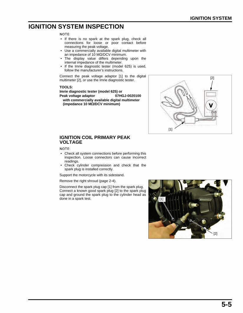
5-5
dummyheaddummyhead
IGNITION SYSTEM
IGNITION SYSTEM INSPECTION
• If there is no spark at the spark plug, check allconnections for loose or poor contact beforemeasuring the peak voltage.
• Use a commercially available digital multimeter withan impedance of 10 MΩ/DCV minimum.
• The display value differs depending upon theinternal impedance of the multimeter.
• If the Imrie diagnostic tester (model 625) is used,follow the manufacturer’s instructions.
Connect the peak voltage adaptor [1] to the digitalmultimeter [2], or use the Imrie diagnostic tester.
IGNITION COIL PRIMARY PEAK VOLTAGE
• Check all system connections before performing thisinspection. Loose connectors can cause incorrectreadings.
• Check cylinder compression and check that thespark plug is installed correctly.
Support the motorcycle with its sidestand.
Remove the right shroud (page 2-4).
Disconnect the spark plug cap [1] from the spark plug.Connect a known good spark plug [2] to the spark plugcap and ground the spark plug to the cylinder head asdone in a spark test.
TOOLS:Imrie diagnostic tester (model 625) orPeak voltage adaptor 07HGJ-0020100
with commercially available digital multimeter (impedance 10 MΩ/DCV minimum)
[1]
[2]
[2]
[1]
61K26000.book Page 5 Friday, July 12, 2013 3:51 PM

5-6
dummyheaddummyhead
IGNITION SYSTEM
Do not disconnectthe ignition coil
primary wire.
With the ignition coil primary wire connected, connectthe peak voltage adaptor or Imrie tester to the ignitioncoil primary terminal [1] and ground.
Turn the ignition switch ON.Shift the transmission into neutral.Check the initial voltage at this time.The battery voltage should be measured.If the initial voltage cannot be measured, follow thechecks in the troubleshooting table (page 5-3).
Crank the engine with the electric starter with thethrottle grip fully opened and read the ignition coilprimary peak voltage.
If the peak voltage is abnormal, refer to thetroubleshooting on page 5-3.
Install the removed parts in the reverse order ofremoval.
CKP SENSOR PEAK VOLTAGE
• Check cylinder compression and check that thespark plug is installed correctly.
Disconnect the ECM 33P (Black) connector.
Connect the peak voltage adaptor or Imrie diagnostictester to the ECM 33P (Black) connector [1] terminals.
Turn the ignition switch ON and shift the transmission inneutral.
Crank the engine with the electric starter and measurethe CKP sensor peak voltage.
If the peak voltage measured at the ECM connector isabnormal, measure the peak voltage at the CKP sensorwire connectors.
TOOLS:Imrie diagnostic tester (model 625) orPeak voltage adaptor 07HGJ-0020100
with commercially available digital multimeter (impedance 10 MΩ/DCV minimum)
CONNECTION:Pink/blue terminal (+) – Body ground (–)
Avoid touching thespark plug and
tester probes toprevent electric
shock. PEAK VOLTAGE: 100 V minimum
IGNITION COIL
(+)
(–)From IGNITION SWITCH
P/BuECM
TOOLS:Imrie diagnostic tester (model 625) orPeak voltage adaptor 07HGJ-0020100 with commercially available digital multimeter (impedance 10 MΩ/DCV minimum)Test probe 07ZAJ-RDJA110
CONNECTION: Blue/yellow (+) – White/yellow (–)
PEAK VOLTAGE: 0.7 V minimum
[1]
W/Y
Bu/Y
61K26000.book Page 6 Friday, July 12, 2013 3:51 PM

5-7
dummyheaddummyhead
IGNITION SYSTEM
Turn the ignition switch OFF.Disconnect the alternator 4P connector [1] and connectthe peak voltage tester or adaptor probes to theconnector terminals of the CKP sensor side.
In the same manner as at the ECM 33P (Black)connector, measure the peak voltage and compare it tothe voltage measured at the ECM 33P (Black)connector.
• If the peak voltage measured at the ECM isabnormal and the one measured at the CKP sensoris normal, the wire harness has an open circuit orloose connection.
• If the peak voltage of the CKP sensor side is lowerthan standard value, follow the checks described inthe troubleshooting on page 5-3.
If the CKP sensor is faulty, replace the CKP sensor.
Install the removed parts in the reverse order ofremoval.
IGNITION COILREMOVAL/INSTALLATIONRemove the right shroud (page 2-4).
Disconnect the spark plug cap from the spark plug.
Disconnect the ignition coil wire connectors [1].Remove the bolts [2] and ignition coil [3].
Installation is in the reverse order of removal.
CONNECTION: Blue/yellow (+) – White/yellow (–)
Bu/Y
CKP SENSOR
W/Y
(+)
(–)
[1]
[2]
[3]
61K26000.book Page 7 Friday, July 12, 2013 3:51 PM

5-8
dummyheaddummyhead
IGNITION SYSTEM
IGNITION TIMING • The ignition timing can not be adjusted since the
ECM is factory preset. • Before inspection, make sure that the engine idle
speed is within specification (page 3-8). If not, adjustthe idle air screw before proceeding.
Start the engine, let it idle until warmed up to the normaloperating temperature.
Stop the engine and connect a timing light to the sparkplug wire.
Remove the timing hole cap from the left crankcasecover.
Start the engine and let it idle.
If the engine idle speed is abnormal, inspect the idle airscrew before proceeding.
The ignition timing is correct if the index notch [1] on theleft crankcase cover aligns with the "F" mark [2] on theflywheel.
If the ignition timing is incorrect, perform the ECMinitializing procedure (page 4-24) and recheck theignition timing.
If the ignition timing is still incorrect, replace the ECMwith a known-good one and recheck.
Apply engine oil to a new timing hole cap O-ring.Install and tighten the timing hole cap to the specifiedtorque.
Read themanufacturer’sinstructions for
timing lightoperation.
IDLE SPEED:1,400 ± 100 min-1 (rpm)
TORQUE:6.0 N·m (0.6 kgf·m, 4.4 lbf·ft)
[1]
[2]
61K26000.book Page 8 Friday, July 12, 2013 3:51 PM

6-1
6
dummytext
6. ELECTRIC STARTER SYSTEM
SERVICE INFORMATION·····························6-2
TROUBLESHOOTING···································6-2
SYSTEM LOCATION·····································6-3
SYSTEM DIAGRAM······································ 6-3
STARTER MOTOR ······································· 6-4
STARTER RELAY········································· 6-9
61K26000.book Page 1 Friday, July 12, 2013 3:51 PM

6-2
dummyheaddummyhead
ELECTRIC STARTER SYSTEMELECTRIC STARTER SYSTEM
SERVICE INFORMATIONGENERAL • A weak battery may be unable to turn the starter motor quickly enough, or supply adequate ignition current. • When checking the starter system, always follow the steps in the troubleshooting.
SPECIFICATIONSUnit: mm (in)
TROUBLESHOOTING
ITEM STANDARD SERVICE LIMITStarter motor brush length 6.7 – 7.3 (0.26 - 0.29) 3.5 (0.14)
Unusual condition Probable cause (Check in numerical order)Starter motor Starter motor does not turn 1. Loose or poor contact on related connectors and terminals
2. Fuse3. Weak battery4. Faulty starter relay switch5. Faulty starter motor6. Loose connection, open or short circuit in starter motor
cable7. Faulty starter switch8. Open circuit in starter relay switch ground circuit9. Open or short circuit in starter relay switch power circuit
– Faulty engine stop switch– Faulty clutch switch– Faulty neutral switch– Faulty neutral diode
10.Loose contact or open circuit in related wiresStarter motor turns only when the transmission is in neutral (Starter motor does not turn when the transmission is in any gear with the sidestand retracted and clutch lever pulled in)
1. Loose or poor contact on related connectors and terminals2. Faulty clutch switch3. Loose contact or open circuit in related wires
Starter motor turns only when the transmission is in any gear with the sidestand retracted and clutch lever pulled in (Starter motor does not turn when the transmission is in neutral and clutch lever released)
1. Loose or poor contact on related connectors and terminals2. Faulty neutral diode3. Faulty neutral switch4. Loose contact or open circuit in related wires
Starter motor turns slowly 1. Low battery voltage2. Poorly connected battery terminal cable3. Poorly connected starter motor cable4. Faulty starter motor5. Poorly connected battery ground cable
Starter motor turns, but engine does not turn
1. Starter motor is running backwards– Case assembled improperly– Terminals connected improperly
2. Faulty starter clutch3. Damaged or faulty starter idle gear and/or reduction gear
Starter relay switch "Clicks", but engine does not turn over
1. Crankshaft does not turn due to engine problems
61K26000.book Page 2 Friday, July 12, 2013 3:51 PM
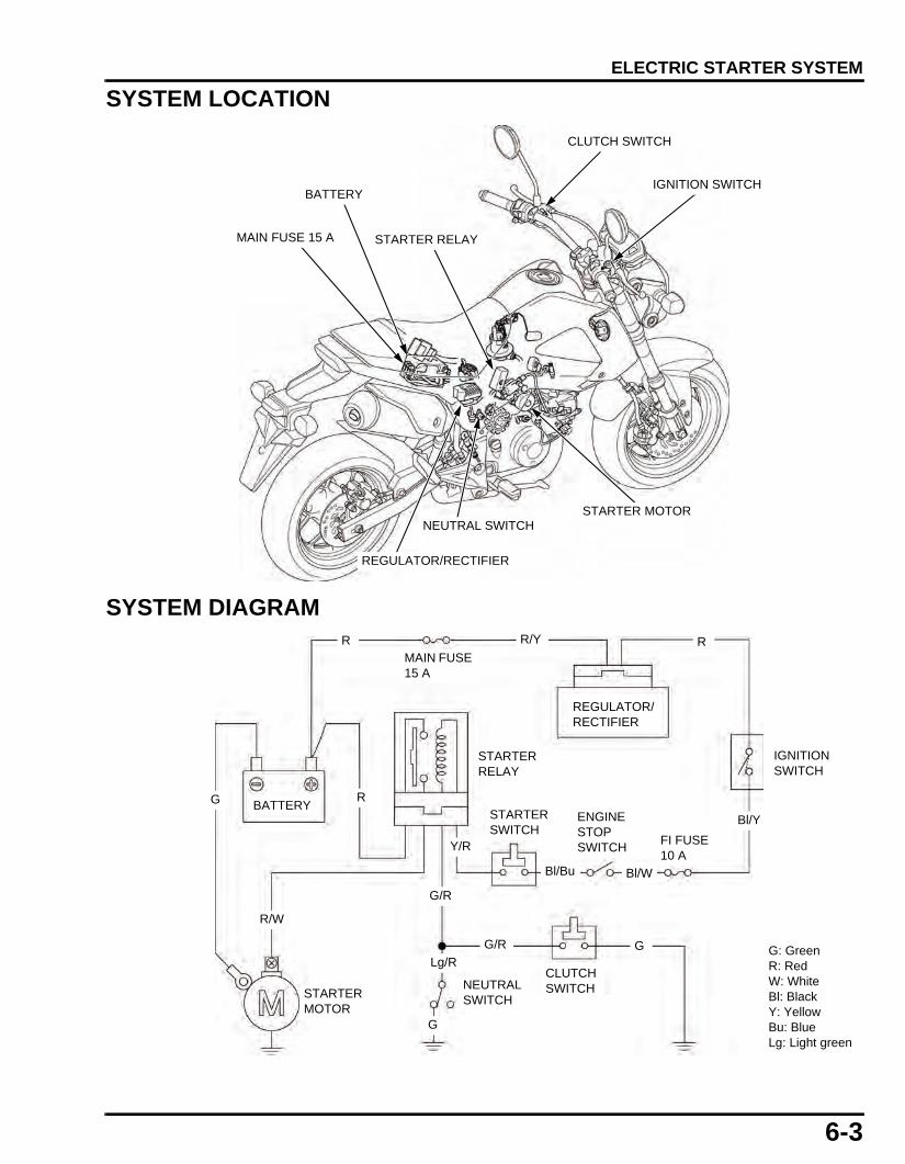
6-3
dummyheaddummyhead
ELECTRIC STARTER SYSTEM
SYSTEM LOCATION
SYSTEM DIAGRAM
STARTER MOTOR
REGULATOR/RECTIFIER
STARTER RELAY
BATTERY
MAIN FUSE 15 A
NEUTRAL SWITCH
CLUTCH SWITCH
IGNITION SWITCH
G: GreenR: RedW: WhiteBl: BlackY: YellowBu: BlueLg: Light green
RG
R/Y
Bl/Y
G/R
BATTERY
REGULATOR/RECTIFIER
STARTER MOTOR
IGNITION SWITCH
MAIN FUSE 15 A
R
CLUTCH SWITCH
G
R/W
STARTER RELAY
R
NEUTRAL SWITCH
G
Lg/R
G/R
FI FUSE 10 A
ENGINE STOP SWITCH
STARTER SWITCH
Bl/WBl/Bu
Y/R
61K26000.book Page 3 Friday, July 12, 2013 3:51 PM

6-4
dummyheaddummyhead
ELECTRIC STARTER SYSTEM
STARTER MOTORREMOVAL/INSTALLATIONRemove the right shroud (page 2-3).
Remove the rubber cap and terminal nut [1], thendisconnect the starter motor cable.
Remove the bolts [2], ground cable [3] and starter motorfrom the engine.
Remove the O-ring [1] from the starter motor.
Installation is in the reverse order of removal.
• Replace the O-ring with a new one. • Apply engine oil to the O-ring surface.
[1]
[2]
[3]
TORQUE:Starter motor terminal nut7.0 N·m (0.7 kgf·m, 5.2 lbf·ft)
[1]
61K26000.book Page 4 Friday, July 12, 2013 3:51 PM
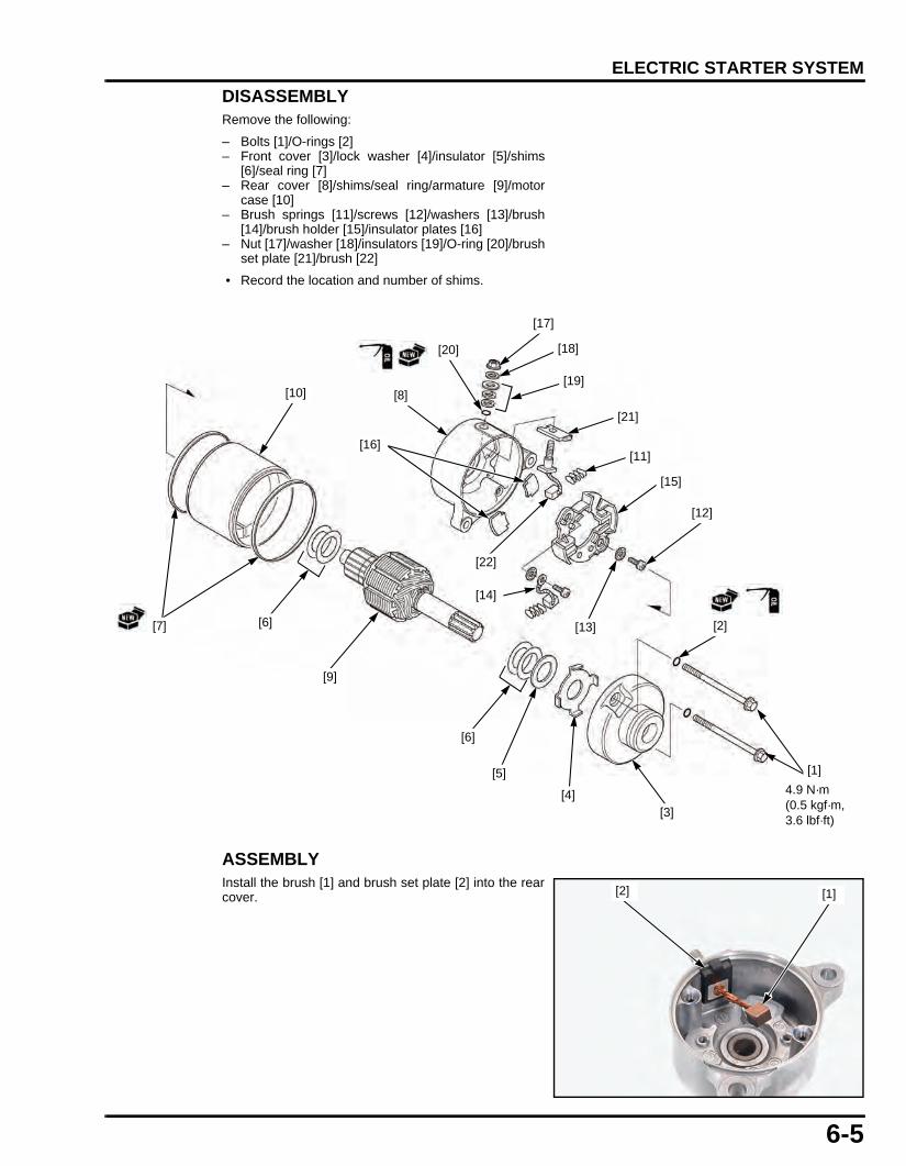
6-5
dummyheaddummyhead
ELECTRIC STARTER SYSTEM
DISASSEMBLYRemove the following:
– Bolts [1]/O-rings [2]– Front cover [3]/lock washer [4]/insulator [5]/shims
[6]/seal ring [7]– Rear cover [8]/shims/seal ring/armature [9]/motor
case [10]– Brush springs [11]/screws [12]/washers [13]/brush
[14]/brush holder [15]/insulator plates [16]– Nut [17]/washer [18]/insulators [19]/O-ring [20]/brush
set plate [21]/brush [22]
• Record the location and number of shims.
ASSEMBLYInstall the brush [1] and brush set plate [2] into the rearcover.
[20]
[17]
[18]
[10]
[6]
[3]
[2]
[9]
[15]
[11]
[8][19]
[4]
[21]
[22]
[13]
[12]
[7]
[5]
[6]
[16]
4.9 N·m (0.5 kgf·m, 3.6 lbf·ft)
[1]
[14]
[1][2]
61K26000.book Page 5 Friday, July 12, 2013 3:51 PM

6-6
dummyheaddummyhead
ELECTRIC STARTER SYSTEM
Install the insulator plates [1] onto the rear cover [2].
Install the brush holder [1], brush [2], washers [3] andscrews [4] into the rear cover [5] as shown.
Apply oil to the oil seal lips [1].
Install the armature [1] into the motor case [2] whileholding the armature shaft tightly to keep the magnet ofthe motor case from pulling the armature shaft againstit.
The coil may be damaged if the magnet pulls thearmature against the motor case.
[1]
[2]
[1]
[2]
[3]/[4][5]
[1]
[1] [2]
61K26000.book Page 6 Friday, July 12, 2013 3:51 PM

6-7
dummyheaddummyhead
ELECTRIC STARTER SYSTEM
Install the springs [1] and brushes [2] to the brushholder [3].
Install a new seal ring [1].
Install the shims [2] onto the armature shaft.
Install the rear cover [3] while pushing the brushes intothe brush holder and aligning the brush set plate tabwith the motor case groove.
Install the samenumber of shims inthe same locations
as noted duringdisassembly.
Install the shims [1], insulator [2] and a new seal ring[3].
Install the lock washer [4] to the front cover [5].
Install the front cover.
• When installing the front cover, take care to preventdamaging the oil seal lip with the armature shaft.
Align the index lines on the covers and motor case.
Apply oil to new O-rings [1] and install them onto themotor case bolts [2].
Install and tighten the starter motor case bolts to thespecified torque.
[1]
[2][3]
Install the samenumber of shims inthe same locations
as noted duringdisassembly.
Align [1][3]
[2]
[1] [2]
[3] [5]
[4]
TORQUE:4.9 N·m (0.5 kgf·m, 3.6 lbf·ft)
Align
[1]
[2]
61K26000.book Page 7 Friday, July 12, 2013 3:51 PM

6-8
dummyheaddummyhead
ELECTRIC STARTER SYSTEM
INSPECTIONCheck the oil seal [1] of the front cover [2] fordeterioration or damage, and needle bearing [3] forwear or damage.
Check the commutator bars [1] of the armature [2] fordiscoloration, wear or damage.
Clean the metallic debris off between commutator bars.
Replace the armature with a new one if necessary.
Check for continuity between pair of commutator bars[1].There should be continuity.
Check for continuity between each commutator bar [1]and the armature shaft [2].There should be no continuity.
[1] [2]
[3]
Do not use emery orsand paper on the
commutator.
[1]
[2]
CONTINUITY: [1]
NO CONTINUITY: [1]
[2]
61K26000.book Page 8 Friday, July 12, 2013 3:51 PM

6-9
dummyheaddummyhead
ELECTRIC STARTER SYSTEM
Check for continuity between the insulated brush [1]and cable terminal [2].There should be continuity.
Check for continuity between the insulated brush [1]and rear cover [2].There should be no continuity.
STARTER RELAYREMOVAL/INSTALLATIONRemove the right shroud (page 2-4).
Remove the starter relay [1] from the stay.Disconnect the starter relay 5P connector [2].
Installation is in the reverse order of removal.
OPERATION INSPECTIONRemove the right shroud (page 2-4).
Turn the ignition switch "ON".Push the starter switch.The system is normal if the starter relay clicks.
If you hear the relay "CLICK", but starter does not turnor If you don’t hear the relay "CLICK", inspect thestarter relay continuity (page 6-10).
CONTINUITY: [1]
[2]
NO CONTINUITY: [1]
[2]
[1]
[2]
61K26000.book Page 9 Friday, July 12, 2013 3:51 PM
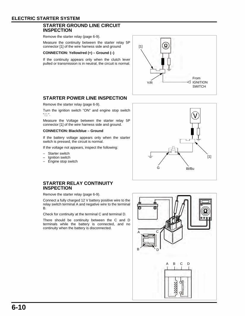
6-10
dummyheaddummyhead
ELECTRIC STARTER SYSTEM
STARTER GROUND LINE CIRCUIT INSPECTIONRemove the starter relay (page 6-9).
Measure the continuity between the starter relay 5Pconnector [1] of the wire harness side and ground
If the continuity appears only when the clutch leverpulled or transmission is in neutral, the circuit is normal.
STARTER POWER LINE INSPECTIONRemove the starter relay (page 6-9).
Turn the ignition switch "ON" and engine stop switch" ".
Measure the Voltage between the starter relay 5Pconnector [1] of the wire harness side and ground.
If the battery voltage appears only when the starterswitch is pressed, the circuit is normal.
If the voltage not appears, inspect the following:
– Starter switch– Ignition switch– Engine stop switch
STARTER RELAY CONTINUITY INSPECTIONRemove the starter relay (page 6-9).
Connect a fully charged 12 V battery positive wire to therelay switch terminal A and negative wire to the terminalB.
Check for continuity at the terminal C and terminal D.
There should be continuity between the C and Dterminals while the battery is connected, and nocontinuity when the battery is disconnected.
CONNECTION: Yellow/red (+) – Ground (–)
[1]
From IGNITION SWITCH
Y/R
CONNECTION: Black/blue – Ground
[1]
Bl/BuG
A B C D
CA
B D
61K26000.book Page 10 Friday, July 12, 2013 3:51 PM

7-1
7
dummytext
7. FUEL SYSTEM
SERVICE INFORMATION·····························7-2
FUEL LINE INSPECTION······························7-3
FUEL TANK···················································7-4
FUEL FILTER/FUEL PUMP UNIT ·················7-5
AIR CLEANER HOUSING·····························7-7
THROTTLE BODY ········································ 7-8
FUEL INJECTOR ·········································· 7-9
EVAP PURGE CONTROL SOLENOID VALVE ····································· 7-10
EVAP CANISTER········································ 7-11
61K26000.book Page 1 Friday, July 12, 2013 3:51 PM

7-2
dummyheaddummyhead
FUEL SYSTEMFUEL SYSTEM
SERVICE INFORMATIONGENERAL • Work in a well ventilated area. Smoking or allowing flames or sparks in the work area where gasoline is stored can cause a fire
or explosion. • Do not snap the throttle valve from full open to full close after the throttle cable has been removed. It may cause incorrect idle
operation. • Seal the intake port with tape or a clean cloth to keep dirt and debris from entering the engine after the throttle body has been
removed. • Do not damage the throttle body. It may cause incorrect throttle valve operation. • Prevent dirt and debris from entering the throttle bore and air passages after the throttle body has been removed. Clean them
using compressed air if necessary. • Do not loosen or tighten the white painted nut and screw of the throttle body. Loosening or tightening them can cause throttle
valve and idle control failure.
SPECIFICATIONS
TORQUE VALUES
FUEL SYSTEM
TOOLS
ITEM SPECIFICATIONSThrottle body identification number GQY9AIdle air screw standard opening 2 turns out from the fully seated positionThrottle grip freeplay 2 – 6 mm (0.08 - 0.24 in)Fuel pressure at idle 270 - 323 kPa (2.75 - 3.29 kgf/cm2, 39 - 47 psi)Fuel pump flow (at 12 V) 162 cm3 minimum/10 seconds
ITEM Q'TYTHREAD TORQUE
REMARKSDIA. (mm) N·m (kgf·m, lbf·ft)
Fuel filter stay nut 2 6 12 (1.2, 9) For tightening sequence See page 7-5
Fuel pump setting plate nut 2 6 12 (1.2, 9)Fuel pump setting plate special nut 2 6 12 (1.2, 9)Throttle cable stay screw 1 5 3.4 (0.3, 2.5)Connecting hose band screw 1 4 1.5 (0.2, 1.1)
Fuel Pressure Gauge Attachment Set070MJ-K260100
Fuel Adapter Male "B" 07AAJ-S6MA200, quantity 2. Use with fuel line P/N: 17570-K26-901 (U.S.A. only)
Fuel Pressure Gauge Set07406-0040004
07406-004000C or 07406-004000B (U.S.A. only)
61K26000.book Page 2 Friday, July 12, 2013 3:51 PM

7-3
dummyheaddummyhead
FUEL SYSTEM
FUEL LINE INSPECTIONCheck the fuel feed hose and quick connect fittingsconnecting area for deterioration, damage or leakage.Replace the fuel line if necessary.
Check the fuel pump unit mounting area for leakage.Replace the fuel pump packing and/or O-ring ifnecessary (page 7-5).
FUEL PRESSURE TESTRemove the left shroud (page 2-4).
Relieve the fuel pressure (page 7-4) and disconnect thefuel injector side quick connect fitting.
Attach the fuel pressure gauge, attachments.
Temporarily connect the fuel pump 5P connector andbattery cables.Start the engine and let it idle.Read the fuel pressure.
If the fuel pressure is out of specified, inspect thefollowing:
– Fuel line (page 7-3)– Fuel pump unit (page 7-5)– Fuel filter (page 7-5)
After inspection, relieve the fuel pressure (page 7-4).Remove the special tools from the fuel pump.Connect the quick connect fitting (page 7-5).
FUEL FLOW INSPECTIONRelieve the fuel pressure (page 7-4) and disconnect thefuel injector side quick connect fitting (page 7-5).
Place the end of the fuel hose into an approvedgasoline container.
Temporarily connect the fuel pump 5P connector andbattery cables.
Turn the ignition switch ON.Measure the amount of fuel flow.
• The fuel pump operates for 2 seconds. Repeat 5times to obtain the total measuring time.
• After the test, return the fuel to the fuel tank.
If fuel flow is less than specified, inspect the following:
– Fuel pump unit (page 7-5)– Fuel filter (page 7-5)
Connect the quick connect fitting (page 7-5).
TOOLS:[1]: Fuel pressure gauge 07406-0040004[2]: Pressure gauge attachment 070MJ-K260100U.S.A. TOOLS:Fuel Pressure Gauge, 0-0100 psi 07406-004000C or
07406-004000BFuel Adapter Male "B" 07AAJ-S6MA200, quantity 2. Use with fuel line P/N: 17570-K26-901 (U.S.A. only)
STANDARD: 270 – 323 kPa (2.75 - 3.29 kgf/cm2, 39 - 47 psi)
[1]
[2]
Wipe off spilled outgasoline.
Amount of fuel flow:162 cm3 minimum/10 seconds
61K26000.book Page 3 Friday, July 12, 2013 3:51 PM

7-4
dummyheaddummyhead
FUEL SYSTEM
FUEL TANKREMOVAL/INSTALLATION • Before disconnecting fuel feed hose, relieve
pressure from the system by following theprocedures below.
• This motorcycle uses resin in the manufacture of thefuel feed hose. Do not bend or twist the fuel feedhose.
Turn the ignition switch OFF.
To relieve the fuel pressure, start the engine anddisconnect the fuel pump connector.
Disconnect the battery negative (–) cable.
Remove the following:
– Shroud (page 2-4).– Fuel tank cover (page 2-6).
Remove the bolts [1]/[2] and nuts [3].
Release the fuel tank from the frame.
Disconnect the fuel pump 5P connector [1].
Check the fuel quick connect fitting [1] for dirt, andclean if necessary.
Disconnect the fuel feed hose [2] (page 7-5).
Install the removed parts in the reverse order ofremoval.
• The fuel pump will run for about 2 seconds, and fuelpressure will rise.
• Repeat 2 or 3 times, and check that there is noleakage in the fuel supply system.
[2]/[3]
[1]
Place a shop towelover the quickconnect fitting.
[1]
[2]
61K26000.book Page 4 Friday, July 12, 2013 3:51 PM

7-5
dummyheaddummyhead
FUEL SYSTEM
QUICK CONNECTOR FITTINGREMOVAL
1. Push the retainer [1] forward.
2. Press down the retainer [1] and hold.
Disconnect the connector [2] from the fuel pumpjoint/ fuel injector joint.
Check the retainer condition and replace it ifnecessary.
• Prevent the remaining fuel in the fuel feed hose fromflowing out, using a shop towel.
• Be careful not to damage the hose or other parts. • Do not use tools. • If the connector does not move, alternately pull and
push the connector until it comes off easily.
3. To prevent damage and keep foreign matter out,cover the disconnected connector and pipe end withthe plastic bags.
INSTALLATION
1. Press the connector [1] onto the fuel pump joint/fuelinjector joint until the retainer [2] locks with a"CLICK".
• Align the quick connect fitting with the pipe.
If it is hard to connect, put a small amount of engineoil on the pipe end.
2. Make sure the connection is secure; check visuallyand by pulling the connector.
FUEL FILTER/FUEL PUMP UNITREMOVAL • Clean around the fuel pump.
Remove the fuel tank (page 7-4).
Disconnect the fuel hoses [1] and remove the fuel filter.
Remove the nuts [2] and fuel pump guard.
[1]
[2]
[1]
[2]
[1]
Fuel pump side shown:
Place a shop towelover the fuel hose.
[1]
[2]
61K26000.book Page 5 Friday, July 12, 2013 3:51 PM

7-6
dummyheaddummyhead
FUEL SYSTEM
Loosen the four nut [1], washer [2], cap nut [3] andspecial nuts [4] in a criss-cross pattern in several steps.
Remove the nuts and set plates.
Remove the fuel pump.
Remove the outer packing [1] and inner packing [2]from the fuel pump unit grooves.
INSTALLATIONInstall a new inner packing onto the fuel pump unitgroove.
Install a new outer packing onto the fuel pump unitgroove by aligning the tab with the boss of the fuelpump unit.
Apply engine oil to the fuel pump packings seating areaof the fuel tank.
Set the setting plates [1] onto the fuel pump [2] byaligning the hole and boss.
Install fuel pump into the fuel tank by aligning thetriangle marks of the setting plate and fuel tank.
[1]/[2]
[4]
[3]
[1]
[2]
Align
[2]
Align
[1]
Align
61K26000.book Page 6 Friday, July 12, 2013 3:51 PM

7-7
dummyheaddummyhead
FUEL SYSTEM
See from the check hole, check that the outer packing[1] is installed properly.
Install and temporarily tighten the nut, washer, cap nutand special nuts.
Tighten the nuts and special nuts to the specified torquein the specified sequence as shown.
Install the fuel filter stay [1] and two nuts [2].
Tighten the nuts [2] to the specified torque while holdingthe special nut [3] securely.
Install the fuel filter assembly.
• Perform the ECM initializing procedure (page 4-24)if the fuel pump unit is replaced with a new one.
AIR CLEANER HOUSINGREMOVAL/INSTALLATIONRemove the shroud (page 2-4).
Disconnect the IAT sensor connector [1].
[1]
TORQUE:12 N·m (1.2 kgf·m, 9 lbf·ft)
4
3
2
1
TORQUE:12 N·m (1.2 kgf·m, 9 lbf·ft)
[3]
[1] [2]
[1]
61K26000.book Page 7 Friday, July 12, 2013 3:51 PM

7-8
dummyheaddummyhead
FUEL SYSTEM
Disconnect the crankcase breather hose [1] and fuelbreather hose [2].
Loosen the connecting hose band screw [3] anddisconnect the connecting hose from the throttle body.
Remove the bolts [4] and release the tab [5] from the aircleaner housing stay.
Installation is in the reverse order of removal.
Connect the connecting hose to the throttle body whilealigning its groove with the boss of the throttle body.
THROTTLE BODYREMOVAL • If the throttle body is to be disassembled, or
replaced with a new one, perform the TP sensorreset procedure (page 4-23).
Remove the shroud (page 2-4).
Remove the bolt and the throttle drum cover.
Loosen the throttle cable lock nut [1].Remove the throttle cable from the cable bracket andthrottle drum.
Loosen the connecting hose band screw [2] anddisconnect the air cleaner connecting hose.
Disconnect the TP sensor connector [1], fuel injectorconnector [2] and quick connector fitting [3].
Remove the bolts [4] and throttle body.
Installation is in the reverse order of removal.
If the throttle body is disassembled, or is replaced witha new one, perform the TP sensor reset procedure(page 4-23).
DISASSEMBLY/ASSEMBLY • The throttle body is factory pre-set. Do not
disassemble in a way other than shown in thismanual.
• Do not snap the throttle valve from full open to fullclose after the throttle cable has been removed. Itmay cause incorrect idle operation.
• Do not damage the throttle body. It may causeincorrect throttle valve operation.
• Do not loosen or tighten the white painted screw ornut. Removing them can cause throttle bodymalfunction.
[4]
[3] [5]
[2]
[1]
[4]
Be careful not todamage the threadsof the throttle cable.
[2]
[1]
[1]
[2]
[1]
[3]
[4]
[4]
61K26000.book Page 8 Friday, July 12, 2013 3:51 PM

7-9
dummyheaddummyhead
FUEL SYSTEM
Before removing the idle air screw [1], turn it in carefullyto count the number of turns until it seats lightly. Make anote to use as a reference when reinstalling the idle airscrew.
Remove the following:
– Idle air screw [1], spring and O-ring– Screw and throttle cable bracket [2]– Bolts and intake pipe– Torx screws [3], fast idle solenoid valve [4], spring,
valve seat [5] and O-ring
Assemble the throttle body in the reverse order ofdisassembly.
After installation, perform the following:
– Engine idle speed inspection (page 3-8)– TP sensor reset (page 4-23)
FUEL INJECTORREMOVAL/INSTALLATION • Perform the ECM initializing procedure if the fuel
injector is replaced with a new one (page 4-24). • Fuel injector can be serviced with the throttle body
installed on the engine.
Remove the right shroud (page 2-4).
Relieve the fuel pressure (page 7-4) and disconnect thefuel injector side quick connect fitting (page 7-5).
Disconnect the fuel injector 2P connector.
Remove the fuel injector joint mounting bolts and fuelinjector [1] /fuel injector joint [2] from the intake pipe.
Remove the following from the fuel injector.
– Fuel injector joint [2]– O-ring [3]– Seal ring [4]
Check the removed parts for wear or damage andreplace them if necessary.
Installation is in the reverse order of removal.
IDLE AIR SCREW STANDARD OPENING:2 turns out from the fully seated position
TORQUE:Idle solenoid valve torx screw [3]:
3.4 N·m (0.3 kgf·m, 2.5 lbf·ft)Throttle cable bracket screw:
3.4 N·m (0.3 kgf·m, 2.5 lbf·ft)
[2]
[1]
[5]
[3]
[4]
[1]
[4]
[3]
[2]12 N·m(1.2 kgf·m, 9 lbf·ft)
61K26000.book Page 9 Friday, July 12, 2013 3:51 PM
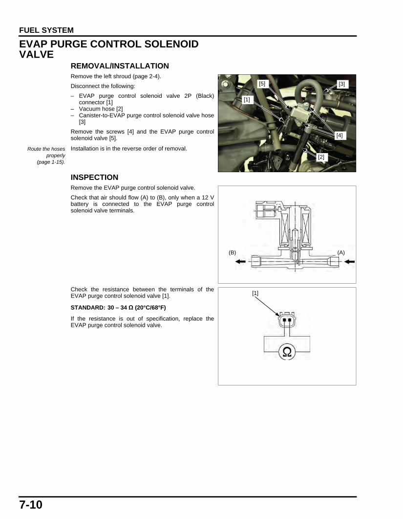
7-10
dummyheaddummyhead
FUEL SYSTEM
EVAP PURGE CONTROL SOLENOID VALVE
REMOVAL/INSTALLATIONRemove the left shroud (page 2-4).
Disconnect the following:
– EVAP purge control solenoid valve 2P (Black)connector [1]
– Vacuum hose [2]– Canister-to-EVAP purge control solenoid valve hose
[3]
Remove the screws [4] and the EVAP purge controlsolenoid valve [5].
Installation is in the reverse order of removal.
INSPECTIONRemove the EVAP purge control solenoid valve.
Check that air should flow (A) to (B), only when a 12 Vbattery is connected to the EVAP purge controlsolenoid valve terminals.
Check the resistance between the terminals of theEVAP purge control solenoid valve [1].
If the resistance is out of specification, replace theEVAP purge control solenoid valve.
Route the hosesproperly
(page 1-15).
[1]
[2]
[5] [3]
[4]
(B) (A)
STANDARD: 30 – 34 Ω (20°C/68°F)
[1]
61K26000.book Page 10 Friday, July 12, 2013 3:51 PM

7-11
dummyheaddummyhead
FUEL SYSTEM
EVAP CANISTERREMOVAL/INSTALLATIONRemove the left shroud (page 2-4).
Disconnect the following:
– Fuel tank breather hose (to fuel tank) [1]– Canister-to-EVAP purge control solenoid valve hose
[2]– EVAP canister breather hose [3]
Remove the EVAP canister [4] from the frame.
Installation is in the reverse order of removal.
[1][3]
[4]
[2]
61K26000.book Page 11 Friday, July 12, 2013 3:51 PM

MEMO
dummyheaddummyhead
61K26000.book Page 12 Friday, July 12, 2013 3:51 PM

8-1
8
dummytext
8. LUBRICATION SYSTEM
SERVICE INFORMATION·····························8-2
TROUBLESHOOTING···································8-2
LUBRICATION SYSTEM DIAGRAM ············8-3
OIL PUMP······················································8-4
OIL PUMP DRIVE GEAR ······························ 8-5
ENGINE OIL STRAINER SCREEN··············· 8-5
ENGINE OIL CENTRIFUGAL FILTER·········· 8-5
61K26000.book Page 1 Friday, July 12, 2013 3:51 PM

8-2
dummyheaddummyhead
LUBRICATION SYSTEMLUBRICATION SYSTEM
SERVICE INFORMATIONGENERAL
• The oil pump can be serviced with the engine installed in the frame. • The service procedures in this section must be performed with the engine oil drained. • When removing and installing the oil pump, use care not to allow dust or dirt to enter the engine. • If any portion of the oil pump is worn beyond the specified service limits, replace the oil pump as an assembly. • After the oil pump has been installed, check that there are no oil leaks.
SPECIFICATIONSUnit: mm (in)
TORQUE VALUES
LUBRICATION SYSTEM
TROUBLESHOOTINGEngine oil level too low • Oil consumption • External oil leak • Worn piston rings • Improperly installed piston rings • Worn valve guide or stem seal • Worn cylinder
Oil contamination • Worn piston rings • Improperly installed piston rings • Worn valve guide or stem seal • Oil not changed frequently enough • Clogged oil strainer screen
Used engine oil may cause skin cancer if repeatedly left in contact with the skin for prolonged periods. Although this is unlikely unless you handle used oil on a daily basis, it is still advisable to thoroughly wash your hands with soap and water as soon as possible after handling used oil.
ITEM STANDARD SERVICE LIMITEngine oil capacity At draining 0.9 liter (0.96 US Qt, 0.20 Imp gal) –
At disassembly 1.1 liters (1.16 US Qt, 0.24 Imp gal) –Recommended engine oil Pro Honda GN4 4-stroke oil (U.S.A. &
Canada) or equivalent motorcycle oilAPI service classification: SG or higher (except oils labeled as energy conserving on the circular API service label)JASO T903 standard: MAViscosity: SAE 10W-30
–
Oil pump rotor Tip clearance – 0.15 (0.006)Body clearance 0.15 – 0.21 (0.006 - 0.008) 0.26 (0.010)Side clearance 0.03 – 0.09 (0.001 - 0.004) 0.15 (0.006)
ITEM Q'TY THREAD TORQUE REMARKSDIA. (mm) N·m (kgf·m, lbf·ft)
Oil centrifugal filter cover bolt 3 6 12 (1.2, 9) Apply locking agent to the threads.
Oil pump assembly bolt 2 5 5.2 (0.5, 3.8)
61K26000.book Page 2 Friday, July 12, 2013 3:51 PM

8-3
dummyheaddummyhead
LUBRICATION SYSTEM
LUBRICATION SYSTEM DIAGRAM
CRANKSHAFT
OIL STRAINER SCREEN
OIL PUMP
CAMSHAFT
OIL CENTRIFUGAL FILTER
COUNTERSHAFT
MAINSHAFT
PISTON
61K26000.book Page 3 Friday, July 12, 2013 3:51 PM
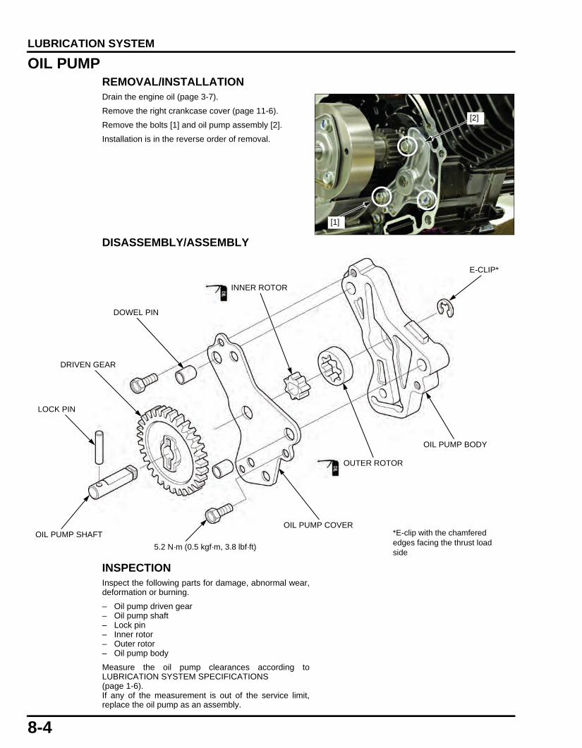
8-4
dummyheaddummyhead
LUBRICATION SYSTEM
OIL PUMPREMOVAL/INSTALLATIONDrain the engine oil (page 3-7).
Remove the right crankcase cover (page 11-6).
Remove the bolts [1] and oil pump assembly [2].
Installation is in the reverse order of removal.
DISASSEMBLY/ASSEMBLY
INSPECTIONInspect the following parts for damage, abnormal wear,deformation or burning.
– Oil pump driven gear– Oil pump shaft– Lock pin– Inner rotor– Outer rotor– Oil pump body
Measure the oil pump clearances according toLUBRICATION SYSTEM SPECIFICATIONS (page 1-6).If any of the measurement is out of the service limit,replace the oil pump as an assembly.
[2]
[1]
INNER ROTOR
DRIVEN GEAR
OIL PUMP SHAFT
LOCK PIN
5.2 N·m (0.5 kgf·m, 3.8 lbf·ft)
OUTER ROTOR
OIL PUMP BODY
E-CLIP*
DOWEL PIN
OIL PUMP COVER*E-clip with the chamfered edges facing the thrust load side
61K26000.book Page 4 Friday, July 12, 2013 3:51 PM

8-5
dummyheaddummyhead
LUBRICATION SYSTEM
OIL PUMP DRIVE GEARREMOVAL/INSTALLATIONRemove the clutch assembly (page 11-7).
Remove the oil pump drive gear [1] and pin [2].Check the oil pump drive gear for damage, replace it ifnecessary.
Installation is in the reverse order of removal.
• Install the oil pump drive gear by aligning the geargroove with the pin.
ENGINE OIL STRAINER SCREENRemove the right crankcase cover (page 11-6).
Remove the oil strainer screen [1] and clean it in non-flammable or high flash point solvent.
Install the oil strainer screen with its tapered side facingthe crankcase side and thinner edge facing up asshown.
Install the right crankcase cover (page 11-6).
ENGINE OIL CENTRIFUGAL FILTERCLEANINGRemove the right crankcase cover (page 11-6).
Remove the bolts [1], oil centrifugal filter cover [2] andgasket [3].
Clean the oil centrifugal filter cover and inside of thedrive plate using a clean lint-free cloth.
Install a new gasket [1] with its sealed side facing the oilcentrifugal filter cover.
Apply locking agent to the oil centrifugal filter cover boltthreads as specified.
Install the oil centrifugal filter cover and bolts.Tighten the bolts to the specified torque.
Install the right crankcase cover (page 11-6).
Be careful not todrop the pin into the
crankcase.
[2] [1]
Align
[1]
TORQUE:12 N·m (1.2 kgf·m, 9 lbf·ft)
[2]
[1]
[2]
[3]
CLEAN
61K26000.book Page 5 Friday, July 12, 2013 3:51 PM

MEMO
dummyheaddummyhead
61K26000.book Page 6 Friday, July 12, 2013 3:51 PM

9-1
9
dummytext
9. CYLINDER HEAD/VALVES
SERVICE INFORMATION·····························9-2
TROUBLESHOOTING···································9-4
COMPONENT LOCATION····························9-5
CYLINDER COMPRESSION TEST···············9-6
CAMSHAFT/ROCKER ARM························· 9-6
CYLINDER HEAD ········································· 9-9
CAM CHAIN TENSIONER ·························· 9-15
61K26000.book Page 1 Friday, July 12, 2013 3:51 PM

9-2
dummyheaddummyhead
CYLINDER HEAD/VALVESCYLINDER HEAD/VALVES
SERVICE INFORMATIONGENERAL • This section covers service of the cylinder head, valves, camshaft and cam chain tensioner. • The cylinder head, valves, camshaft and cam chain tensioner services can be done with the engine installed in the frame. • When disassembling, mark and store the disassembled parts to ensure that they are reinstalled in their original locations. • Clean all disassembled parts with cleaning solvent and dry them by blowing them off with compressed air before inspection. • Camshaft lubricating oil is fed through oil passages in the cylinder head. Clean the oil passages before assembling cylinder
head. • Be careful not to damage the mating surfaces when removing the cylinder head.
SPECIFICATIONSUnit: mm (in)
TORQUE VALUESCYLINDER HEAD/VALVES
ITEM STANDARD SERVICE LIMITCylinder compression 1.1 MPa (11.2 kgf/cm2, 160 psi) at
600 min-1 (rpm)–
Cylinder head warpage – 0.05 (0.002)Camshaft Cam lobe height IN 32.657 – 32.897 (1.2857 - 1.2952) 32.33 (1.2728)
EX 32.481 – 32.721 (1.2788 - 1.2882) 31.78 (1.2512)Valve, valve guide
Valve clearance IN 0.10 ± 0.02 (0.004 ± 0.001) – EX 0.17 ± 0.02 (0.007 ± 0.001) –
Valve stem O.D. IN 4.975 – 4.990 (0.1959 - 0.1965) 4.965 (0.1955)EX 4.955 – 4.970 (0.1951 - 0.1957) 4.945 (0.1947)
Valve guide I.D. IN/EX 5.000 – 5.012 (0.1969 - 0.1973) 5.03 (0.198)Stem-to-guide clearance IN 0.010 – 0.037 (0.0004 - 0.0015) 0.065 (0.003)
EX 0.030 – 0.057 (0.0012 - 0.0022) 0.085 (0.003)Valve guide projection IN/EX 10.1 – 10.3 (0.40 - 0.41) – Valve seat width IN/EX 1.0 (0.04) 1.6 (0.06)
Valve spring free length IN/EX 33.14 (1.305) 31.5 (1.240)Cam chain tensioner
Push rod O.D. 11.985 – 12.000 (0.4718 - 0.4724) 11.94 (0.470)Spring free length 111.3 (4.38) 109 (4.29)
ITEM Q'TYTHREAD TORQUE
REMARKSDIA. (mm) N·m (kgf·m, lbf·ft)
Cylinder head cap bolt 4 8 24 (2.4, 18) Apply engine oil to the threads and seating surface.
Cam sprocket bolt 1 8 27 (2.8, 20) Apply engine oil to the threads and seating surface.
Tappet adjust nut 2 5 9.0 (0.9, 6.6) Apply engine oil to the threads and seating surface.
Cam chain tensioner sealing bolt 1 14 22 (2.2, 16)Cam chain tensioner arm pivot bolt 1 8 16 (1.6, 12)Cam chain guide lower roller pivot bolt 1 6 10 (1.0, 7)Timing hole cap 1 14 6.0 (0.6, 4.4)Crankshaft hole cap 1 30 8.0 (0.8, 5.9)
61K26000.book Page 2 Friday, July 12, 2013 3:51 PM
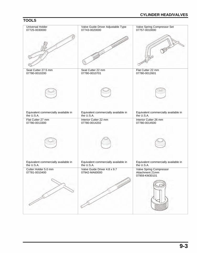
9-3
dummyheaddummyhead
CYLINDER HEAD/VALVES
TOOLS
Universal Holder07725-0030000
Valve Guide Driver Adjustable Type07743-0020000
Valve Spring Compressor Set07757-0010000
Seat Cutter 27.5 mm07780-0010200
Equivalent commercially available in the U.S.A.
Seat Cutter 22 mm07780-0010701
Equivalent commercially available in the U.S.A.
Flat Cutter 22 mm07780-0012601
Equivalent commercially available in the U.S.A.
Flat Cutter 27 mm07780-0013300
Equivalent commercially available in the U.S.A.
Interior Cutter 22 mm07780-0014202
Equivalent commercially available in the U.S.A.
Interior Cutter 26 mm07780-0014500
Equivalent commercially available in the U.S.A.
Cutter Holder 5.0 mm07781-0010400
Valve Guide Driver 4.8 x 9.707942-MA60000
Valve Spring Compressor Attachment 21mm07959-KM30101
61K26000.book Page 3 Friday, July 12, 2013 3:51 PM

9-4
dummyheaddummyhead
CYLINDER HEAD/VALVES
TROUBLESHOOTING • Engine top-end problems usually affect engine performance. These problem can be diagnosed by a compression test or by
tracing engine noises to the top-end with a sounding rod stethoscope. • If the performance is poor at low speeds, check for white smoke in the crankcase breather hose. If the hose is smoky, check for
a seized piston ring.
Compression too low, hard starting or poor performance at low speed • Valves:
– Incorrect valve clearance– Burned or bent valves– Incorrect valve timing– Broken valve spring– Valve stuck open
• Cylinder head:– Uneven valve seating– Leaking or damaged cylinder head gasket– Warped or cracked cylinder head
• Worn cylinder, piston or piston rings
Compression too high, overheating or knocking • Excessive carbon build-up on piston head or combustion chamber
Excessive smoke • Cylinder head:
– Worn valve stem or valve guide– Damaged stem seal
• Worn cylinder, piston or piston rings
Excessive noise • Cylinder head:
– Incorrect valve clearance– Sticking valve or broken valve spring– Damaged or worn camshaft– Loose or worn cam chain– Worn or damaged cam chain guide roller/sprocket– Worn or damaged cam chain tensioner– Worn cam sprocket teeth– Worn rocker arm and/or shaft– Faulty cam chain tensioner
• Worn cylinder, piston or piston rings
Rough idle • Low cylinder compression • Faulty fuel system
Valve Guide Reamer 5.01007984-MA60001
07984-MA6000D (U.S.A. only)
61K26000.book Page 4 Friday, July 12, 2013 3:51 PM

9-5
dummyheaddummyhead
CYLINDER HEAD/VALVES
COMPONENT LOCATION
24 N·m (2.4 kgf·m, 18 lbf·ft)
16 N·m (1.6 kgf·m, 12 lbf·ft)
22 N·m (2.2 kgf·m, 16 lbf·ft)
27 N·m (2.8 kgf·m, 20 lbf·ft)
10 N·m (1.0 kgf·m, 7 lbf·ft)
61K26000.book Page 5 Friday, July 12, 2013 3:51 PM

9-6
dummyheaddummyhead
CYLINDER HEAD/VALVES
CYLINDER COMPRESSION TESTWarm up the engine to normal operating temperature.
Stop the engine and disconnect the spark plug cap.
Remove the spark plug (page 3-5).
Install the compression gauge [1] in the spark plug hole.
Turn the ignition switch ON.Shift the transmission into neutral.
Open the throttle all the way and crank the engine withthe electric starter until the gauge reading stops rising.
If compression is high, it indicates that carbon depositshave accumulated on the combustion chamber and/orthe piston head.
If compression is low, pour 3 – 5 cc of engine oil into thecylinder through the spark plug hole and recheck thecompression.
If the compression increases from the previous value,check the cylinder, piston and piston rings for thefollowing:
– Leaking cylinder head gasket– Worn piston ring– Worn cylinder and piston
If the compression is the same as the previous value,check the valves for leakage.
CAMSHAFT/ROCKER ARMREMOVALRemove the Shroud (page 2-4).
Remove the valve adjusting hole caps and set thepiston to the TDC (Top Dead Center) on thecompression stroke.
Remove the bolt [1] and sealing washer [2].
Remove the bolts [1], cam sprocket cover [2] and O-ring[3].
STANDARD:1.1 MPa (11.2 kgf/cm2, 160 psi) at 600 min-1 (rpm)
[1]
[1]/[2]
[3]
[2]
[1]
61K26000.book Page 6 Friday, July 12, 2013 3:51 PM

9-7
dummyheaddummyhead
CYLINDER HEAD/VALVES
Hold the cam sprocket [1] by using the special tool.
Remove the washer bolt [3], cam sprocket from thecamshaft and cam chain [4] off the cam sprocket.
Attach a piece of wire to the cam chain to prevent itfrom falling into the crankcase.
Remove the bolt [1] and rocker arm shaft set plate [2]from the cylinder head.
Remove the rocker arm shafts [3], rocker arms andneedle bearings.
Remove the camshaft [1] from the cylinder head whileturning so its groove [2] is facing up as shown.
INSTALLATIONApply engine oil to the camshaft whole surface.Apply molybdenum disulfide oil to the decompressorcam [3] and arm sliding area.
Install the camshaft into the cylinder head with itsgroove facing upward as shown.
Apply engine oil to the sliding surfaces of the rockerarm shafts [1] and needle bearings [2].
Apply engine oil to the inner surfaces of the rocker arms[3] and sliding surfaces of the rollers [4].
• The exhaust rocker arm shaft is longer than theintake rocker arm shaft.
TOOLS:[2] Universal holder 07725-0030000
[1]
[3]
[2][4]
[1]
[2][3]
[3]
[1]
[2]
[3]
[1][3]
[2]
[4]
61K26000.book Page 7 Friday, July 12, 2013 3:51 PM

9-8
dummyheaddummyhead
CYLINDER HEAD/VALVES
Install the rocker arms, needle bearings and rocker armshafts into the cylinder head.
Install the rocker arm shaft set plate [1] with its "OUT"mark [2] facing out as shown.
Install and tighten the bolt [3].
Rotate the crankshaft counterclockwise until the "T"mark [1] on the flywheel is aligned with the index notch[2] on the left crankcase cover.
Apply engine oil to the cam chain [1] and cam sprocket[2] teeth.
Install the cam chain on the cam sprocket with its "O"mark [3] facing out as shown by aligning its tab with thegroove of the camshaft.Install the cam sprocket to the camshaft.
Hold the cam sprocket [1] by using the special tool.
Apply engine oil to the cam sprocket washer bolt [3]threads and seating surface.
Install and tighten the cam sprocket washer bolt tospecified torque.
[3]
[1]
[2]
[2]
[1]
[1]
[2][3]
Align
TOOL:[2] Universal Holder 07725-0030000
TORQUE:27 N·m (2.8 kgf·m, 20 lbf·ft)
[1]
[3]
[2]
61K26000.book Page 8 Friday, July 12, 2013 3:51 PM

9-9
dummyheaddummyhead
CYLINDER HEAD/VALVES
Apply engine oil to a new O-ring [1] and install it into thecam sprocket cover [2] groove.
Install the cam sprocket cover and tighten the bolts [3].
Pour 4.0 cc minimum of engine oil into the push rod.
Install a new sealing washer [1] and bolt [2], thentighten it.
Apply engine oil to the new crankshaft hole cap O-ringand timing hole cap O-ring, then install them to thecaps.Install the crankshaft hole cap and timing hole cap tothe left crankcase cover.
Install the following:
– Valve adjusting hole caps (page 3-6).– Shroud (page 2-4).
INSPECTIONInspect the following parts for damage, abnormal wear,deformation, burning or clogs in oil passages.
– Rocker arms/shafts/needle bearings– Cam sprocket– Camshaft– Camshaft bearings– Cam chain guide B– Cam sprocket– Decompressor system
Measure each part according to CYLINDER HEAD/VALVES SPECIFICATIONS (page 1-7).Replace any part if it is out of service limit.
CYLINDER HEADREMOVALPerform the ECM initializing procedure if the cylinderhead is replaced or is overhauled (page 4-24).
Remove the following:
– Cam sprocket (page 9-6)– Exhaust pipe/muffler (page 2-10)– O2 sensor cap– Intake manifold mounting bolts/holder plate/O-ring
Disconnect the spark plug cap.
Remove the cylinder head bolts [1].Loosen the cylinder head nuts in a crisscross pattern intwo or three steps.Remove the four nuts, sealing washer [2] and threewashers [3].
Remove the cylinder head.
[1]
[2]
[3]
TORQUE:Crankshaft hole cap 8.0 N·m (0.8 kgf·m, 5.9 lbf·ft)Timing hole cap 6.0 N·m (0.6 kgf·m, 4.4 lbf·ft)
[1]
[2]
[2]
[3][1]
61K26000.book Page 9 Friday, July 12, 2013 3:51 PM

9-10
dummyheaddummyhead
CYLINDER HEAD/VALVES
Remove the gasket [1] and dowel pins [2].
INSTALLATIONClean the cylinder and cylinder head mating surface.Install the dowel pins and a new gasket onto thecylinder.
Install the cylinder head onto the cylinder.
Apply engine oil to the seating surface and threads ofthe cylinder head nuts.Install new sealing washer [1], three washers [2] andtighten the cylinder head nuts to the specified torque ina crisscross pattern.
Install and tighten the cylinder head mounting bolts [3].
Connect the spark plug cap.
Install the following:
– Cam sprocket (page 9-7)– Exhaust pipe/muffler (page 2-10)– O2 sensor cap– Intake manifold mounting bolts/holder plate/O-ring
Perform the ECM initializing procedure if the cylinderhead is replaced or is overhauled (page 4-24).
DISASSEMBLYRemove the following:
– Spark plug (page 3-5)– Camshaft/rocker arm (page 9-6)– O2 sensor
Remove the valve cotters [1] using the special tools.
Remove the valve spring compressor and remove thefollowing:
– Valve spring retainers– Valve springs– Valve spring seats– Valves– Valve stem seals
[2]
[1]
TORQUE:24 N·m (2.4 kgf·m, 18 lbf·ft)
[1]
[2][3]
To prevent loss oftension, do not
compress the valvesprings more than
necessary toremove the cotters.
TOOLS:[2] Valve spring compressor 07757-0010000[3] Valve spring compressor attachment
07959-KM30101
Mark all parts duringdisassembly so
they can be placedback in their original
locations.
[2]
[3]
[1]
61K26000.book Page 10 Friday, July 12, 2013 3:51 PM

9-11
dummyheaddummyhead
CYLINDER HEAD/VALVES
Avoid damaging themating surface and
valve seat surfaces.
Remove the carbon deposits form the combustionchamber [1] and clean off the cylinder head gasketsurface.
INSPECTIONInspect the following parts for damage, abnormal wear,deformation, burning or clogs in oil passages.
– Cylinder head– Valve spring– Valves– Valve guides
Measure each part and clearance according toCYLINDER HEAD/VALVES SPECIFICATIONS (page1-7).Replace any part if it is out of service limit.
ASSEMBLY
[1]
SPRING RETAINER
BOLT
CAMSHAFT
VALVE
ROCKER ARM
SPRING SEAT
VALVE SPRING
VALVE STEM SEAL
ROCKER ARM SHAFT
VALVE COTTERS
SET PLATE
CLIP
VALVE GUIDE
NEEDLE BEARING
61K26000.book Page 11 Friday, July 12, 2013 3:51 PM

9-12
dummyheaddummyhead
CYLINDER HEAD/VALVES
Blow through the oil passage in the cylinder head withcompressed air.Install the valve spring seats [1].Apply engine oil to the new valve stem seals [2] andinstall them.
Apply engine oil to the valve stem [3] outer surface andstem end.Insert the valves into the valve guides while turningthem slowly to avoid damage to the valve stem seals.
Install the valve springs with the tightly wound coilsfacing the combustion chamber.
Install the valve spring retainer [1].
Install the valve cotters [2] using the special tools.
Support the cylinderhead above the
work bench surfaceto prevent valve
damage.
Place a suitable tool [1] onto the valve stem [2].
Tap the tool gently to seat the cotters [3] firmly using aplastic hammer.
Install the following:
– Camshaft/rocker arm (page 9-7)– Spark plug (page 3-5)– O2 sensor (page 4-28)
[1]
[2]
[3]
To combustion chamber
To prevent loss oftension, do not
compress the valvespring more than
necessary to installthe cotters.
TOOLS:[3] Valve spring compressor 07757-0010000[4] Valve spring compressor attachment
07959-KM30101
[3]
[4]
[1]/[2]
[1]
[2]
[3]
61K26000.book Page 12 Friday, July 12, 2013 3:51 PM

9-13
dummyheaddummyhead
CYLINDER HEAD/VALVES
VALVE GUIDE REPLACEMENTChill new valve guides in a freezer for about 1 hour.
• Be sure to wear heavy gloves to avoid burns whenhandling the heated cylinder head.
• Using a torch to heat the cylinder head may causewarpage.
• Drive new guides from the camshaft side while thecylinder head is still heated.
• Perform the TP sensor reset/ECM initializingprocedure if the valve guide is replaced with a newone.
Heat the cylinder head to 130 – 140°C (275 – 290°F)with a hot plate or oven. Do not heat the cylinder headbeyond 150°C (300°F). Use temperature indicatorsticks, available from welding supply stores, to be surethe cylinder head is heated to the proper temperature.
Support the cylinder head and drive the valve guides [1]out of the cylinder head from the combustion chamberside.
Take out new valve guides from the freezer.
Drive new clips [1] and valve guides [2] into the cylinderhead to the specified height from the cylinder head.
Let the cylinder head cool to room temperature.
Ream new valve guides after installation.
• Take care not to tilt or lean the reamer in the guidewhile reaming.
• Use cutting oil on the reamer during this operation.
Insert the reamer from the combustion chamber side ofthe cylinder head and always rotate the reamerclockwise.
Clean the cylinder head thoroughly to remove anymetal particles after reaming and reface the valve seat.
TOOL:[2] Valve guide driver, 5.0 mm 07942-MA60000
[2]
[1]
TOOL:[3] Valve guide adjusting driver 07743-0020000
VALVE GUIDE PROJECTION:IN/EX: 10.1 – 10.3 mm (0.40 – 0.41 in)
[3]
[1]/[2]
10.1 – 10.3 mm(0.40 – 0.41 in)
TOOL:[1] Valve guide reamer, 5.0 mm 07984-MA60001
or 07984-MA6000D (U.S.A. only)
[1]
61K26000.book Page 13 Friday, July 12, 2013 3:51 PM

9-14
dummyheaddummyhead
CYLINDER HEAD/VALVES
VALVE SEAT INSPECTION/REFACINGINSPECTION
Clean the intake and exhaust valves thoroughly toremove carbon deposits.
Apply a light coat of Prussian Blue to the valve seats.Tap the valve against the valve seat several times usinga hand-lapping tool [1], without rotating the valve tomake a clear pattern.
Remove the valve and inspect the valve seat facewidth.
Inspect the valve seat face for:
• Damaged face:– Replace the valve and reface the valve seat
• Uneven seat width:– Bent or collapsed valve stem; Replace the valve
and reface the valve seat • Contact area (too low or too high area):
– Reface the valve seat
REFACING
Reface the valve seat using the following tools.
• Follow the refacer manufacturer’s operatinginstructions.
• Be careful not to grind the seat more thannecessary.
1. Use a 45° seat cutter, remove any roughness orirregularities from the seat.
2. Use a 32° flat cutter, remove the top 1/4 of theexisting valve seat material.
3. Use a 60° interior cutter, remove the bottom 1/4 ofthe existing valve seat material.
4. Using a 45° seat cutter, cut the seat to the properwidth.
5. After cutting the seat, apply lapping compound to thevalve face, and lap the valve using light pressure.
• Excessive lapping pressure may deform or damagethe seat.
• Change the angle of lapping tool [1] frequently toprevent uneven seat wear.
• Do not allow lapping compound to enter the guides.
After lapping, wash any residual compound off thecylinder head and valve and recheck the seat contact.
Equivalentcommercially
available in theU.S.A.
TOOLS:Cutter holder, 5.0 mm 07781-0010400Seat cutter, 27.5 mm (45° IN) 07780-0010200Seat cutter, 22 mm (45° EX) 07780-0010701Flat cutter, 27 mm (32° IN) 07780-0013300Flat cutter, 22 mm (32° EX) 07780-0012601Interior cutter, 26 mm (60° IN) 07780-0014500Interior cutter, 22 mm (60° EX) 07780-0014202
VALVE SEAT WIDTH: 1.0 mm (0.04 in)
[1]
Old seat width
32°
60°
Old seat width
[1]
61K26000.book Page 14 Friday, July 12, 2013 3:51 PM

9-15
dummyheaddummyhead
CYLINDER HEAD/VALVES
CAM CHAIN TENSIONERREMOVALRemove the flywheel (page 12-5).
Remove the following:
– Cam chain tensioner sealing bolt [1] and washer [2]– Tensioner spring [3]– Push rod [4]
Remove the following:
– Pivot bolt/washer [1]– Tensioner arm/upper roller [2] and collar [3]– Bolt [4] and lower roller [5]
INSTALLATIONInstall the cam chain tensioner lower roller [1] andtighten the pivot bolt [2] to the specified torque.
Install the cam chain tensioner arm/upper roller [3],collar [4], and pivot bolt/washer [5], then tighten it to thespecified torque.
Install the following:
– Push rod [1]– Tensioner spring [2]
Install and tighten the sealing bolt [3] with a new sealingwasher [4] to the specified torque.
[1]/[2]
[4]
[3]
[4]
[1][2]
[5]
[3]
TORQUE: 10 N·m (1.0 kgf·m, 7 lbf·ft)
TORQUE: 16 N·m (1.6 kgf·m, 12 lbf·ft)
[2] [1]
[3][4]
[5]
TORQUE: 22 N·m (2.2 kgf·m, 16 lbf·ft)
[3]
[1]
[2]
[4]
61K26000.book Page 15 Friday, July 12, 2013 3:51 PM

9-16
dummyheaddummyhead
CYLINDER HEAD/VALVES
Remove the bolt [1] and sealing washer [2].Pour 4.0 cc minimum of engine oil into the push rod.
Install and tighten the bolt with a new sealing washer.
Install the flywheel (page 12-6).
INSPECTIONInspect the following parts for damage, abnormal wear,deformation, burning or clogs in oil passages.
– Tensioner spring– Push rod/check valve– Valves– Valve guides
Measure each part and clearance according toCYLINDER HEAD/VALVES SPECIFICATIONS (page1-7).Replace any part if it is out of service limit.
[1]
[2]
61K26000.book Page 16 Friday, July 12, 2013 3:51 PM

21-1
21
dummytext
INDEXAAIR CLEANER ································································3-4AIR CLEANER HOUSING
FUEL SYSTEM···························································7-7ALTERNATOR CHARGING COIL ································18-6ALTITUDE SETTING ····················································4-25BBANK ANGLE SENSOR···············································4-27BATTERY······································································18-5BODY COVER/TAIL COVER··········································2-6BRAKE FLUID·······························································3-11BRAKE FLUID REPLACEMENT/AIR BLEEDING ········17-5BRAKE LIGHT SWITCH
LIGHTS/METERS/SWITCHES·································19-9MAINTENANCE ·······················································3-12
BRAKE PAD/DISC ························································17-7BRAKE PADS WEAR ···················································3-10BRAKE PEDAL ···························································17-14BRAKE SYSTEM ··························································3-11BRAKE/TAILLIGHT·······················································19-4CCABLE & HARNESS ROUTING ···································1-15CAM CHAIN TENSIONER ············································9-15CAMSHAFT/ROCKER ARM ···········································9-6CHARGING SYSTEM INSPECTION ····························18-5CLUTCH········································································11-7CLUTCH SYSTEM························································3-12COMPONENT LOCATION
ALTERNATOR/STARTER CLUTCH ························12-3CLUTCH/GEARSHIFT LINKAGE·····························11-5CRANKCASE/TRANSMISSION/KICKSTARTER/CRANKSHAFT ·························································13-5CYLINDER HEAD/VALVES ·······································9-5ENGINE REMOVAL/INSTALLATION·······················14-3FRONT WHEEL/SUSPENSION/STEERING ···········15-5HYDRAULIC BRAKE················································17-4REAR WHEEL/SUSPENSION ·································16-4
CRANKCASE································································13-6CRANKCASE BREATHER ·············································3-5CRANKSHAFT······························································13-7CYLINDER COMPRESSION TEST································9-6CYLINDER HEAD···························································9-9CYLINDER/PISTON······················································10-3DDRIVE CHAIN ·································································3-9DRIVE CHAIN COVER ···················································2-9EECM ··············································································4-26ECM INITIALIZING PROCEDURE ·······························4-24EMISSION CONTROL SYSTEMS································1-25ENGINE IDLE SPEED ····················································3-8ENGINE OIL····································································3-7ENGINE OIL CENTRIFUGAL FILTER····························8-5ENGINE OIL STRAINER SCREEN ································8-5ENGINE REMOVAL······················································14-4EOT SENSOR·······························································4-27EVAP CANISTER ·························································7-11EVAP PURGE CONTROL SOLENOID VALVE ············7-10EXHAUST PIPE/MUFFLER··········································2-10FFLYWHEEL/STARTER CLUTCH ·································12-5FORK ············································································15-8FRONT BRAKE CALIPER ··········································17-11FRONT FENDER····························································2-3FRONT MASTER CYLINDER·······································17-8FRONT WHEEL ····························································15-6FUEL GAUGE/FUEL LEVEL SENSOR ························19-7FUEL INJECTOR····························································7-9FUEL LINE INSPECTION···············································7-3FUEL PUMP UNIT ··························································7-5FUEL TANK
FUEL SYSTEM···························································7-4FUEL TANK COVER·······················································2-6GGEARSHIFT LINKAGE ···············································11-10HHANDLEBAR ······························································15-16
HANDLEBAR SWITCHES············································ 19-9HEADLIGHT ··························································· 2-7,19-4HEADLIGHT AIM·························································· 3-12HORN ··········································································· 19-5IIGNITION COIL
IGNITION SYSTEM ··················································· 5-7IGNITION SWITCH······················································· 19-8IGNITION SYSTEM INSPECTION
IGNITION SYSTEM ··················································· 5-5IGNITION TIMING
IGNITION SYSTEM ··················································· 5-8LLEFT CRANKCASE COVER········································ 12-4LICENSE LIGHT··························································· 19-5LUBRICATION & SEAL POINTS·································· 1-13LUBRICATION SYSTEM DIAGRAM······························ 8-3MMAINTENANCE SCHEDULE········································· 3-3MIL CIRCUIT INSPECTION ········································· 4-22MIL CODE INDEX ·························································· 4-9MIL TROUBLESHOOTING··········································· 4-10MODEL IDENTIFICATION ············································· 1-3NNEUTRAL SWITCH···················································· 19-10NUTS, BOLTS, FASTENERS······································· 3-14OO2 SENSOR································································· 4-28OIL PUMP ······································································ 8-4OIL PUMP DRIVE GEAR ··············································· 8-5PPGM-FI SYMPTOM TROUBLESHOOTING··················· 4-5PGM-FI TROUBLESHOOTING INFORMATION············ 4-6RREAR BRAKE CALIPER ············································ 17-13REAR FENDER A··························································· 2-8REAR FENDER B··························································· 2-9REAR MASTER CYLINDER········································· 17-9REAR UNDER COVER ·················································· 2-7REAR WHEEL······························································ 16-5REGULATOR/RECTIFIER ··········································· 18-7RIGHT CRANKCASE COVER ····································· 11-6SSEAT ·············································································· 2-3SERVICE INFORMATION
ALTERNATOR STARTER CLUTCH························ 12-2BATTERY/CHARGING SYSTEM ···························· 18-2BODY PANELS/EXHAUST SYSTEM························ 2-2CLUTCH/GEARSHIFT LINKAGE ···························· 11-2CRANKCASE/TRANSMISSION/KICKSTARTER/CRANKSHAFT························································· 13-2CYLINDER HEAD/VALVES······································· 9-2CYLINDER/PISTON················································· 10-2ELECTRIC STARTER SYSTEM································ 6-2ENGINE REMOVAL/INSTALLATION ······················ 14-2FRONT WHEEL/SUSPENSION/STEERING··········· 15-2FUEL SYSTEM ·························································· 7-2HYDRAULIC BRAKE ··············································· 17-2IGNITION SYSTEM ··················································· 5-2LIGHTS/METERS/SWITCHES ································ 19-2LUBRICATION SYSTEM ··········································· 8-2MAINTENANCE························································· 3-2PGM-FI SYSTEM······················································· 4-2REAR WHEEL/SUSPENSION································· 16-2
SERVICE RULES··························································· 1-2SHOCK ABSORBER···················································· 16-7SHROUD ········································································ 2-4SIDESTAND
MAINTENANCE······················································· 3-13SIDESTAND SWITCH················································ 19-10SPARK PLUG································································· 3-5SPECIFICATIONS·························································· 1-5SPEEDOMETER ·························································· 19-6STARTER MOTOR························································· 6-4STARTER RELAY ·························································· 6-9STATOR ······································································· 12-4STEERING HEAD BEARINGS····································· 3-14
INDEX
61K26000.book Page 1 Friday, July 12, 2013 3:51 PM

21-2
dummytext
INDEX
STEERING STEM ······················································ 15-20SUSPENSION······························································ 3-13SWINGARM ································································· 16-8SYSTEM DIAGRAM
BATTERY/CHARGING SYSTEM ···························· 18-4ELECTRIC STARTER SYSTEM································ 6-3IGNITION SYSTEM ··················································· 5-4PGM-FI SYSTEM······················································· 4-4
SYSTEM LOCATIONBATTERY/CHARGING SYSTEM ···························· 18-4ELECTRIC STARTER SYSTEM································ 6-3IGNITION SYSTEM ··················································· 5-4LIGHTS/METERS/SWITCHES ································ 19-3PGM-FI SYSTEM······················································· 4-3
TTECHNICAL FEATURES············································· 1-23THROTTLE BODY ························································· 7-8THROTTLE OPERATION ·············································· 3-4TORQUE VALUES······················································· 1-10TP SENSOR RESET PROCEDURE···························· 4-23TRANSMISSION ························································ 13-10
TROUBLESHOOTINGBATTERY/CHARGING SYSTEM·····························18-3BODY PANELS/EXHAUST SYSTEM ························ 2-2CLUTCH/GEARSHIFT LINKAGE·····························11-4CRANKCASE/TRANSMISSION/KICKSTARTER/CRANKSHAFT ·························································13-4CYLINDER HEAD/VALVES ······································· 9-4CYLINDER/PISTON·················································10-2ELECTRIC STARTER SYSTEM ································ 6-2FRONT WHEEL/SUSPENSION/STEERING ···········15-4HYDRAULIC BRAKE ···············································17-3IGNITION SYSTEM···················································· 5-3LUBRICATION SYSTEM ··········································· 8-2REAR WHEEL/SUSPENSION ·································16-3
TURN SIGNAL LIGHT ··················································19-4TURN SIGNAL RELAY ···············································19-11VVALVE CLEARANCE ····················································· 3-6VS SENSOR ·······························································19-11WWHEELS/TIRES ···························································3-14WIRING DIAGRAM·······················································20-2
61K26000.book Page 2 Friday, July 12, 2013 3:51 PM

MEMO
Copy of 61KRN50000.fm Page 5 Tuesday, August 4, 2009 11:58 AM

MEMO
61KRN500.book 5 ページ 2009年7月1日 水曜日 午後2時54分