Embed Size (px)
Citation preview

2003 ENGINE
Engine Mechanical - 2.2L (L61) - Saturn L Series
SPECIFICATIONS
FASTENER TIGHTENING SPECIFICATIONS
Fastener Tightening Specifications
ApplicationSpecification
Metric EnglishA/C Compressor-to-Block Bolt 25 N.m 18 lb ftAir Pipe Bolts 25 N.m 18 lb ftAir Pipe Nut 16 N.m 11 lb ftBalance Shaft Chain Guide (Adjustable) Bolt 10 N.m 89 lb inBalance Shaft Chain Guide (Fixed) Bolts 10 N.m 89 lb inBalance Shaft Chain Guide (Upper) Bolts 10 N.m 89 lb inBalance Shaft Chain Tensioner Bolts 10 N.m 89 lb inBalance Shaft Drive Sprockets 55 N.m 41 lb ftBalance Shaft Retaining Bolts 10 N.m 89 lb inBall Stud-to-Steering Knuckle Nuts 100 N.m 74 lb ftBattery Terminal Bolts 17 N.m 13 lb ftCam Cover Bolts-to-Hold J 43649 . See Special Tools and Equipment.
10 N.m 89 lb in
Camshaft Bearing Cap Bolts 10 N.m 89 lb inCamshaft Cover Bolts 10 N.m 89 lb inCamshaft Cover Ground Strap Fastener 10 N.m 89 lb inCamshaft Sprocket Bolts
First Pass 85 N.m 63 lb ft
Final Pass 30 degrees
Connecting Rod Bolts
First Pass 25 N.m 18 lb ft
Final Pass 100 degrees
Coolant Jacket Plug 20 N.m 15 lb inCrankshaft Bearing Cap Initial Torque (Lower Crankcase-to-Block Bolts)
First Pass 20 N.m 15 lb ft
Final Pass 70 degrees
Crankshaft Damper Pulley Bolt
First Pass 100 N.m 74 lb ft
Final Pass 75 degrees
2003 Saturn L200
2003 ENGINE Engine Mechanical - 2.2L (L61) - Saturn L Series
2003 Saturn L200
2003 ENGINE Engine Mechanical - 2.2L (L61) - Saturn L Series
steve
Monday, May 09, 2011 12:51:59 PM Page 1 © 2006 Mitchell Repair Information Company, LLC.
steve
Monday, May 09, 2011 12:52:16 PM Page 1 © 2006 Mitchell Repair Information Company, LLC.

Crankshaft Position Sensor Bolt 10 N.m 89 lb inCrankshaft Pulley Bolt
First Pass 100 N.m 74 lb ft
Final Pass 75 degrees
Cylinder Head Air Bleed Tube Fastener 15 N.m 11 lb inCylinder Head Bolts
First Pass 30 N.m 22 lb ft
Final Pass 155 degrees
Cylinder Head Front Bolts 35 N.m 26 lb ftCylinder Head Front Chaincase Bolts 20 N.m 15 lb ftCylinder Head Oil Gallery Plug 35 N.m 26 lb ftDegas Hose Bracket Bolt 10 N.m 89 lb inDrive Belt Tensioner Bolt 45 N.m 33 lb ftEGR Cover Bolts 25 N.m 18 lb ftEngine Coolant Temperature Sensor 20 N.m 15 lb ftEngine Harness Bracket Bolts 10 N.m 89 lb inEngine Mount Bracket-to-Engine Bolts 90 N.m 66 lb ftEngine Mount-to-Body Bolts 55 N.m 41 lb ftEngine Mount-to-Engine Mount Bracket Bolts 55 N.m 41 lb ftExhaust Manifold Heat Shield Bolts 25 N.m 18 lb ftExhaust Manifold Pipe-to-Exhaust Manifold Nuts 30 N.m 22 lb ftExhaust Manifold Pipe-to-Resonator Bolts 20 N.m 15 lb ftExhaust Manifold Studs-to-Cylinder Head 10 N.m 89 lb inExhaust Manifold-to-Cylinder Head Nuts 12 N.m 9 lb ftFlywheel Bolt
First Pass 53 N.m 39 lb ft
Final Pass 25 degrees
Front Cover-to-Block Bolts 25 N.m 18 lb ftFuel Line Bolt 10 N.m 89 lb inFuel Rail Bracket Stud 10 N.m 89 lb inIgnition Coil-to-Camshaft Cover Bolts 8 N.m 71 lb inIntake Camshaft Rear Bearing Cap Bolts 25 N.m 18 lb ftIntake Manifold Studs 6 N.m 56 lb inIntake Manifold-to-Cylinder Head Bolts 10 N.m 89 lb inIntake Manifold-to-Cylinder Head Nuts 10 N.m 89 lb inIntake Manifold-to-Cylinder Head Studs 6 N.m 60 lb inKnock Sensor Bolt 25 N.m 18 lb inKnock Sensor-to-Engine Block Bolt 25 N.m 18 lb ftLower Crankcase-to-Block Peripheral Bolts 25 N.m 18 lb ft
2003 Saturn L200
2003 ENGINE Engine Mechanical - 2.2L (L61) - Saturn L Series
steve
Monday, May 09, 2011 12:51:59 PM Page 2 © 2006 Mitchell Repair Information Company, LLC.

Lower Engine-to-Transmission Bell Housing Bolts 65 N.m 48 lb ftOil Drain Plug 25 N.m 18 lb ftOil Filter Cap 25 N.m 18 lb ftOil Gallery Plug 35 N.m 26 lb ftOil Gallery Plug (Rear) 60 N.m 44 lb ftOil Level Indicator Tube-to-Intake Manifold Bolt 10 N.m 89 lb inOil Pan-to-Block Bolts 25 N.m 18 lb ftOil Pressure Switch 10 N.m 89 lb inOil pump Gerotor Cover Bolts 6 N.m 53 lb inOil Pump Pressure Relief Valve Plug 40 N.m 3 lb inOxygen Sensor Bolts 30 N.m 22 lb ftPower Steering Pump Bolts 25 N.m 18 lb ftShift Control Rod Pinch Bolt
First Pass 12 N.m 9 lb ft
Final Pass 180 degrees
Spark Plugs 20 N.m 15 lb ftStabilizer Link-to-Strut Assembly 65 N.m 50 lb ftSteering Gear-to-Intermediate Shaft Pinch Bolt 30 N.m 22 lb ftSupport Plate-to-Engine Block 10 N.m 89 lb inSuspension Support Bolts
First Pass 100 N.m 74 lb ft
Final Pass 45 degrees
Thermostat Housing-to-Block Bolts 10 N.m 89 lb inThrottle Body Bolts 10 N.m 89 lb inThrottle Body Nuts 10 N.m 89 lb inThrottle Body Studs-to-Cylinder Head 6 N.m 60 lb inTie Rod end Linkage Installer 45 N.m 35 lb ftTie Rod Nut 60 N.m 45 lb ftTiming Chain Guide (Adjustable) Bolt 10 N.m 89 lb inTiming Chain Guide (Fixed) Bolts 10 N.m 89 lb inTiming Chain Guide (Upper) Bolts 10 N.m 89 lb inTiming Chain Guide Bolt Access Hole Plug 40 N.m 30 lb ftTiming Chain Oil Nozzle Bolt 10 N.m 89 lb inTiming Chain Tensioner Bolts 75 N.m 55 lb ftTorque Converter Bolts 75 N.m 55 lb ftTransmission Nose Bracket Bolts 35 N.m 26 lb ftUpper Bell Housing Bolts 65 N.m 48 lb ftWater Pump Bolts 25 N.m 18 lb ftWheel Bolts (Final Torque) 125 N.m 92 lb ftWheel Bolts (Initial Torque) 63 N.m 46 lb ft
2003 Saturn L200
2003 ENGINE Engine Mechanical - 2.2L (L61) - Saturn L Series
steve
Monday, May 09, 2011 12:51:59 PM Page 3 © 2006 Mitchell Repair Information Company, LLC.
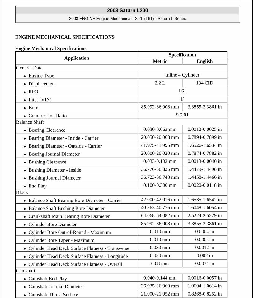
ENGINE MECHANICAL SPECIFICATIONS
Engine Mechanical Specifications
ApplicationSpecification
Metric EnglishGeneral Data
Engine Type Inline 4 Cylinder
Displacement 2.2 L 134 CID
RPO L61
Liter (VIN) F
Bore 85.992-86.008 mm 3.3855-3.3861 in
Compression Ratio 9.5:01
Balance Shaft
Bearing Clearance 0.030-0.063 mm 0.0012-0.0025 in
Bearing Diameter - Inside - Carrier 20.050-20.063 mm 0.7894-0.7899 in
Bearing Diameter - Outside - Carrier 41.975-41.995 mm 1.6526-1.6534 in
Bearing Journal Diameter 20.000-20.020 mm 0.7874-0.7882 in
Bushing Clearance 0.033-0.102 mm 0.0013-0.0040 in
Bushing Diameter - Inside 36.776-36.825 mm 1.4479-1.4498 in
Bushing Journal Diameter 36.723-36.743 mm 1.4458-1.4466 in
End Play 0.100-0.300 mm 0.0020-0.0118 in
Block
Balance Shaft Bearing Bore Diameter - Carrier 42.000-42.016 mm 1.6535-1.6542 in
Balance Shaft Bushing Bore Diameter 40.763-40.776 mm 1.6048-1.6054 in
Crankshaft Main Bearing Bore Diameter 64.068-64.082 mm 2.5224-2.5229 in
Cylinder Bore Diameter 85.992-86.008 mm 3.3855-3.3861 in
Cylinder Bore Out-of-Round - Maximum 0.010 mm 0.0004 in
Cylinder Bore Taper - Maximum 0.010 mm 0.0004 in
Cylinder Head Deck Surface Flatness - Transverse 0.030 mm 0.0012 in
Cylinder Head Deck Surface Flatness - Longitude 0.050 mm 0.002 in
Cylinder Head Deck Surface Flatness - Overall 0.08 mm 0.0031 in
Camshaft
Camshaft End Play 0.040-0.144 mm 0.0016-0.0057 in
Camshaft Journal Diameter 26.935-26.960 mm 1.0604-1.0614 in
Camshaft Thrust Surface 21.000-21.052 mm 0.8268-0.8252 in
2003 Saturn L200
2003 ENGINE Engine Mechanical - 2.2L (L61) - Saturn L Series
steve
Monday, May 09, 2011 12:51:59 PM Page 4 © 2006 Mitchell Repair Information Company, LLC.

Connecting Rod
Connecting Rod Bearing Clearance 0.029-0.069 mm 0.0011-0.0027 in
Connecting Rod Bore Diameter - Bearing End 52.118-52.134 mm 2.0519-2.05252 in
Connecting Rod Bore Diameter - Pin End 20.007-20.021 mm 0.7877-0.7882 in
Connecting Rod Side Clearance 0.070-0.370 mm 0.0028-0.0146 in
Connecting Rod Straightness - Bend - Maximum 0.021 mm 0.0083 in
Connecting Rod Straightness - Twist - Maximum 0.04 mm 0.0157 in
Crankshaft
Connecting Rod Journal Diameter 49.000-49.014 mm 1.9291-1.9297 in
Crankshaft End Play 0.050-0.380 mm 0.0012-0.0150 in
Crankshaft Main Bearing Clearance 0.031-0.067 mm 0.0012-0.0026 in
Crankshaft Main Journal Diameter 55.994-56.008 mm 2.2045-2.2050 in
Cylinder Head
Surface Flatness - Block Deck - Transverse 0.030 mm 0.0012 in
Surface Flatness - Block Deck - Longitude 0.050 mm 0.002 in
Surface Flatness - Block Deck - Overall 0.1 mm 0.004 in
Valve Guide Bore - Exhaust 6.000-6.012 mm 0.2362-0.2367 in
Valve Guide Bore - Intake 6.000-6.012 mm 0.2362-0.2367 in
Valve Lifter Bore Diameter - Stationary Lash Adjusters
12.013-12.037 mm 0.4730-0.4739 in
Lubrication System
Oil Pressure - Minimum - @1000 RPM 344.75-551.60 kPa 50-80 psi
Piston Rings
Piston Ring End Gap - First Compression Ring 0.20-0.40 mm 0.008-0.016 in
Piston Ring End Gap - Second Compression Ring 0.35-0.55 mm 0.014-0.022 in
Piston Ring End Gap - Oil Control Ring - Rails 0.25-0.76 mm 0.010-0.030 in
Piston Ring to Groove Clearance - First Compression Ring
0.04-0.08 mm 0.0015-0.0031 in
Piston Ring to Groove Clearance - Second Compression Ring
0.030-0.069 mm 0.0012-0.0027 in
Piston Ring to Groove Clearance - Oil Control Ring 0.090-0.106 mm 0.0035-0.0042 in
Piston Ring Thickness - First Compression Ring 1.170-1.190 mm 0.0461-0.0469 in
Piston Ring Thickness - Second Compression Ring 1.471-1.490 mm 0.0579-0.0587 in
Piston Ring Thickness - Oil Control Ring - Rail - Maximum
0.43 mm 0.0169 in
2003 Saturn L200
2003 ENGINE Engine Mechanical - 2.2L (L61) - Saturn L Series
steve
Monday, May 09, 2011 12:51:59 PM Page 5 © 2006 Mitchell Repair Information Company, LLC.

SEALERS, ADHESIVES, AND LUBRICANTS
Sealers, Adhesives, and Lubricants
Piston Ring Thickness - Oil Control Ring - Spacer 1.574-1.651 mm 0.0620-0.0650 in
Pistons and Pins
Piston - Piston Diameter - @14.5 mm up 85.967-85.982 mm 3.3845-3.3851 in
Piston - Piston Pin Bore Diameter 20.002-20.007 mm 0.07875-0.7877 in
Piston - Piston Ring Grove Width - Top 1.23-1.25 mm 0.0484-0.0492 in
Piston - Piston Ring Grove Width - Second 1.52-1.54 mm 0.0598-0.0606 in
Piston - Piston Ring Grove Width - Oil Control 2.52-2.54 mm 0.0992-0.1000 in
Piston - Piston To Bore Clearance 0.010-0.041 mm 0.0004-0.0016 in
Pin - Piston Pin Clearance to Connecting Rod Bore 0.007-0.026 mm 0.0003-0.0010 in
Pin - Piston Pin Clearance to Piston Pin Bore 0.002-0.012 mm 0.0001-0.0005 in
Pin - Piston Pin Diameter 19.995-20.000 mm 0.7872-0.7874 in
Pin - Piston Pin End Play 0.19-1.16 mm 0.0075-0.0461 in
Valve System
Valves - Valve Face Runout - Maximum 0.04 mm 0.0016 in
Valves - Valve Seat Runout - Maximum 0.05 mm 0.0020 in
Valves - Valve Stem Diameter - Intake 5.955-5.970 mm 0.2344-0.2355 in
Valves - Valve Stem Diameter - Exhaust 5.935-5.950 mm 0.2337-0.2343 in
Valves - Valve Stem to Guide Clearance - Intake 0.030-0.057 mm 0.0012-0.0022 in
Valves - Valve Stem to Guide Clearance - Exhaust 0.050-0.077 mm 0.0020-0.0026 in
Valve Lifters - Valve Lifter Diameter - Stationary Lash Adjuster
11.986-12.000 mm 0.0005-0.0020 in
Valve Lifters - Valve Lifter-to-Bore Clearance - Stationary Lash Adjuster
0.013-0.051 mm 3.2210-3.2299 in
Valve Springs - Valve Spring Load - Closed - @32.5 mm
245.0-271.0 N. - Eng Spec.
Valve Springs - Valve Spring Load - Open - @32.5 mm
525.0-575.0 N. - Eng Spec.
Application Type of Material Part Number
# 6 Intake Rear Camshaft Cap SealantPermatex® Anaerobic Gasket
Maker 51813Balance Shaft Lobes Lubricant 5 W 30 or equivalentCam Lobes Lubricant Engine Oil SupplementConnecting Rod Bearings Lubricant 5 W 30 or equivalent
2003 Saturn L200
2003 ENGINE Engine Mechanical - 2.2L (L61) - Saturn L Series
steve
Monday, May 09, 2011 12:51:59 PM Page 6 © 2006 Mitchell Repair Information Company, LLC.
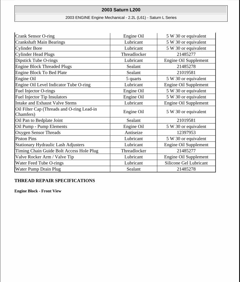
THREAD REPAIR SPECIFICATIONS
Engine Block - Front View
Crank Sensor O-ring Engine Oil 5 W 30 or equivalentCrankshaft Main Bearings Lubricant 5 W 30 or equivalentCylinder Bore Lubricant 5 W 30 or equivalentCylinder Head Plugs Threadlocker 21485277Dipstick Tube O-rings Lubricant Engine Oil SupplementEngine Block Threaded Plugs Sealant 21485278Engine Block To Bed Plate Sealant 21019581Engine Oil 5 quarts 5 W 30 or equivalentEngine Oil Level Indicator Tube O-ring Lubricant Engine Oil SupplementFuel Injector O-rings Engine Oil 5 W 30 or equivalentFuel Injector Tip Insulators Engine Oil 5 W 30 or equivalentIntake and Exhaust Valve Stems Lubricant Engine Oil SupplementOil Filter Cap (Threads and O-ring Lead-in Chamfers)
Engine Oil 5 W 30 or equivalent
Oil Pan to Bedplate Joint Sealant 21019581Oil Pump - Pump Elements Engine Oil 5 W 30 or equivalentOxygen Sensor Threads Antiseize 12397953Piston Pins Lubricant 5 W 30 or equivalentStationary Hydraulic Lash Adjusters Lubricant Engine Oil SupplementTiming Chain Guide Bolt Access Hole Plug Threadlocker 21485277Valve Rocker Arm / Valve Tip Lubricant Engine Oil SupplementWater Feed Tube O-rings Lubricant Silicone Gel LubricantWater Pump Drain Plug Sealant 21485278
2003 Saturn L200
2003 ENGINE Engine Mechanical - 2.2L (L61) - Saturn L Series
steve
Monday, May 09, 2011 12:51:59 PM Page 7 © 2006 Mitchell Repair Information Company, LLC.
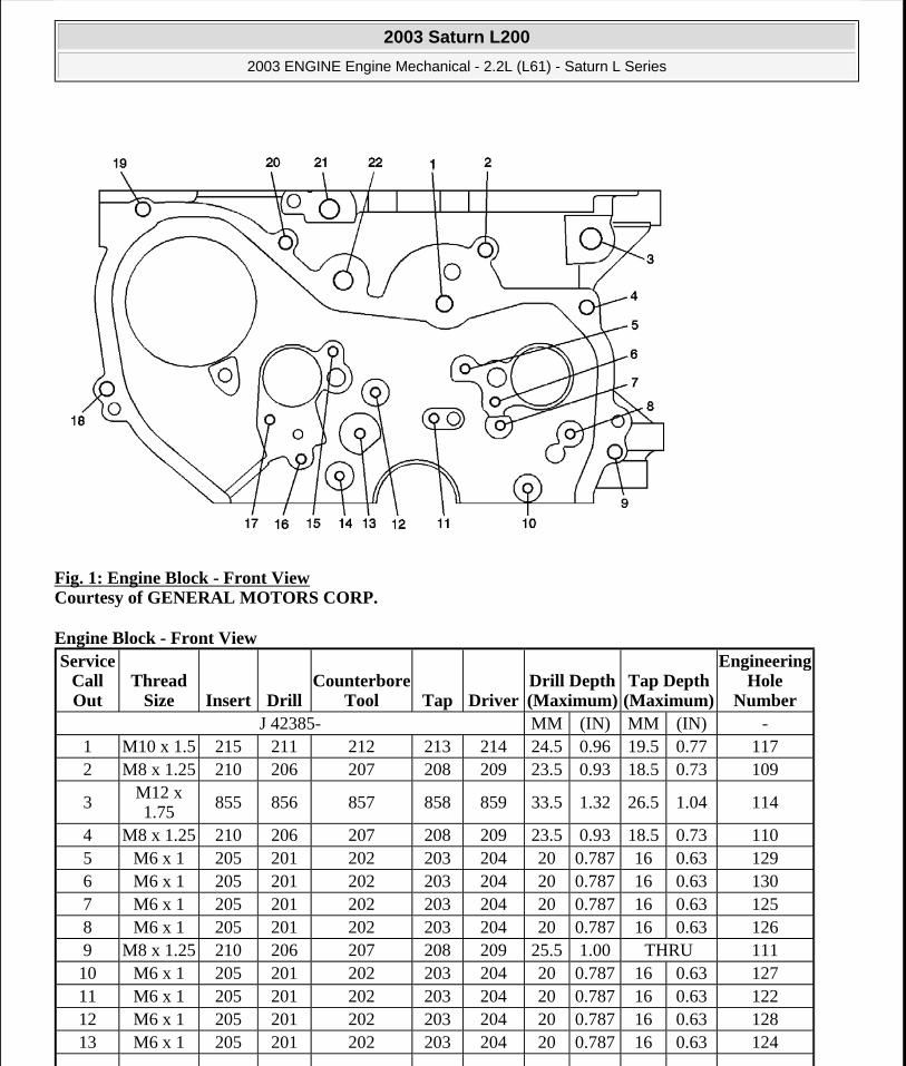
Fig. 1: Engine Block - Front View Courtesy of GENERAL MOTORS CORP.
Engine Block - Front View Service
Call Out
Thread Size Insert Drill
Counterbore Tool Tap Driver
Drill Depth (Maximum)
Tap Depth (Maximum)
Engineering Hole
NumberJ 42385- MM (IN) MM (IN) -
1 M10 x 1.5 215 211 212 213 214 24.5 0.96 19.5 0.77 1172 M8 x 1.25 210 206 207 208 209 23.5 0.93 18.5 0.73 109
3M12 x 1.75 855 856 857 858 859 33.5 1.32 26.5 1.04 114
4 M8 x 1.25 210 206 207 208 209 23.5 0.93 18.5 0.73 1105 M6 x 1 205 201 202 203 204 20 0.787 16 0.63 1296 M6 x 1 205 201 202 203 204 20 0.787 16 0.63 1307 M6 x 1 205 201 202 203 204 20 0.787 16 0.63 1258 M6 x 1 205 201 202 203 204 20 0.787 16 0.63 1269 M8 x 1.25 210 206 207 208 209 25.5 1.00 THRU 11110 M6 x 1 205 201 202 203 204 20 0.787 16 0.63 12711 M6 x 1 205 201 202 203 204 20 0.787 16 0.63 12212 M6 x 1 205 201 202 203 204 20 0.787 16 0.63 12813 M6 x 1 205 201 202 203 204 20 0.787 16 0.63 124
2003 Saturn L200
2003 ENGINE Engine Mechanical - 2.2L (L61) - Saturn L Series
steve
Monday, May 09, 2011 12:51:59 PM Page 8 © 2006 Mitchell Repair Information Company, LLC.

Engine Block - Back View
Fig. 2: Engine Block - Back View Courtesy of GENERAL MOTORS CORP.
Engine Block - Back View
14 M6 x 1 205 201 202 203 204 20 0.787 16 0.63 12315 M6 x 1 205 201 202 203 204 20 0.787 16 0.63 13116 M6 x 1 205 201 202 203 204 20 0.787 16 0.63 11917 M6 x 1 205 201 202 203 204 20 0.787 16 0.63 12018 M8 x 1.25 210 206 207 208 209 23.5 0.93 18.5 0.73 10619 M8 x 1.25 210 206 207 208 209 55 2.17 THRU 11220 M8 x 1.25 210 206 207 208 209 23.5 0.93 18.5 0.73 108
21M12 x 1.75 855 856 857 858 859 33.5 1.32 26.5 1.04 116
22M12 x 1.75
855 856 857 858 859 33.5 1.32 26.5 1.04 115
Service Call Out
Thread Size Insert Drill
Counterbore Tool Tap Driver
Drill Depth (Maximum)
Tap Depth (Maximum)
Engineering Hole
NumberJ 42385- MM (IN) MM (IN) -
M12 x
2003 Saturn L200
2003 ENGINE Engine Mechanical - 2.2L (L61) - Saturn L Series
steve
Monday, May 09, 2011 12:51:59 PM Page 9 © 2006 Mitchell Repair Information Company, LLC.

Engine Block - Left Side View
Fig. 3: Engine Block - Left Side View Courtesy of GENERAL MOTORS CORP.
Engine Block - Left Side View
1 1.75 855 856 857 858 859 39 1.535 33.5 1.32 2042 M16 x 1.5 860 861 862 863 864 21 0.827 15 0.59 2143 M10 x 1.5 215 211 212 213 214 29 1.161 THRU 2064 M8 x 1.25 210 206 207 208 209 18 0.709 THRU 209
5 M8 x 1.25854 No
Flange206 207 208 209 18 0.709 THRU 208
6 M16 x 1.5 860 861 862 863 864 21 0.827 15 0.59 213
7M12 x 1.75
855 856 857 858 859 39 1.535 33.5 1.32 203
Service Call Out
Thread Size Insert Drill
Counterbore Tool Tap Driver
Drill Depth (Maximum)
Tap Depth (Maximum)
Engineering Hole
NumberJ 42385- MM (IN) MM (IN) -
1 M12 x 1.75
865 856 857 858 859 19.50 0.768 12.5 0.49 515
2003 Saturn L200
2003 ENGINE Engine Mechanical - 2.2L (L61) - Saturn L Series
steve
Monday, May 09, 2011 12:51:59 PM Page 10 © 2006 Mitchell Repair Information Company, LLC.
Engine Block - Bottom View
Fig. 4: Engine Block - Bottom View Courtesy of GENERAL MOTORS CORP.
Engine Block - Bottom View
2 M6 x 1.0 205 201 202 203 204 - - - - -
3M12 x 1.75 865 856 857 858 859 19.50 0.768 12.5 0.49 514
4 M10 x 1.5 215 211 212 213 214 23.50 0.925 18.5 0.73 5215 M10 x 1.5 215 211 212 213 214 23.50 0.925 18.5 0.73 5196 M6 x 1.0 205 201 202 203 204 20.50 0.807 16.0 0.63 5137 M6 x 1.0 205 201 202 203 204 20.50 0.807 16.0 0.63 5128 M6 x 1.0 205 201 202 203 204 20.50 0.807 16.0 0.63 5119 M6 x 1.0 205 201 202 203 204 - - - - -
10M12 x 1.75
865 856 857 858 859 19.50 0.768 12.5 0.49 516
2003 Saturn L200
2003 ENGINE Engine Mechanical - 2.2L (L61) - Saturn L Series
steve
Monday, May 09, 2011 12:51:59 PM Page 11 © 2006 Mitchell Repair Information Company, LLC.

Engine Block - Right Side View
Service Call Out
Thread Size Insert Drill
Counterbore Tool Tap Driver
Drill Depth (Maximum)
Tap Depth (Maximum)
Engineering Hole
NumberJ 42385- MM (IN) MM (IN) -
1 M10 x 1.5 514 511 N/A 512 513 60 2.362 53.5 2.11 14152 M10 x 1.5 514 511 N/A 512 513 60 2.362 53.5 2.11 14083 M8 x 1.25 210 206 207 208 209 28 1.102 22 0.87 14254 M10 x 1.5 514 511 N/A 512 513 60 2.362 53.5 2.11 14165 M10 x 1.5 514 511 N/A 512 513 60 2.362 53.5 2.11 14096 M8 x 1.25 210 206 207 208 209 28 1.102 22 0.87 14267 M8 x 1.25 210 206 207 208 209 28 1.102 22 0.87 14328 M10 x 1.5 514 511 N/A 512 513 60 2.362 53.5 2.11 14049 M10 x 1.5 514 511 N/A 512 513 60 2.362 53.5 2.11 141710 M10 x 1.5 514 511 N/A 512 513 60 2.362 53.5 2.11 142211 M10 x 1.5 514 511 N/A 512 513 60 2.362 53.5 2.11 140612 M8 x 1.25 210 206 207 208 209 28 1.102 22 0.87 143113 M8 x 1.25 210 206 207 208 209 28 1.102 22 0.87 143014 M10 x 1.5 514 511 N/A 512 513 60 2.362 53.5 2.11 141215 M10 x 1.5 514 511 N/A 512 513 60 2.362 53.5 2.11 142116 M8 x 1.25 210 206 207 208 209 28 1.102 22 0.87 142917 M10 x 1.5 514 511 N/A 512 513 60 2.362 53.5 2.11 141118 M10 x 1.5 514 511 N/A 512 513 60 2.362 53.5 2.11 142019 M8 x 1.25 210 206 207 208 209 28 1.102 22 0.87 142820 M10 x 1.5 514 511 N/A 512 513 60 2.362 53.5 2.11 141021 M10 x 1.5 514 511 N/A 512 513 60 2.362 53.5 2.11 141922 M8 x 1.25 210 206 207 208 209 28 1.102 22 0.87 142723 M10 x 1.5 514 511 N/A 512 513 60 2.362 53.5 2.11 140524 M10 x 1.5 514 511 N/A 512 513 60 2.362 53.5 2.11 141825 M10 x 1.5 514 511 N/A 512 513 60 2.362 53.5 2.11 141326 M10 x 1.5 514 511 N/A 512 513 60 2.362 53.5 2.11 140327 M8 x 1.25 210 206 207 208 209 28 1.102 22 0.87 142328 M10 x 1.5 514 511 N/A 512 513 60 2.362 53.5 2.11 141429 M10 x 1.5 514 511 N/A 512 513 60 2.362 53.5 2.11 140730 M8 x 1.25 210 206 207 208 209 28 1.102 22 0.87 1424
2003 Saturn L200
2003 ENGINE Engine Mechanical - 2.2L (L61) - Saturn L Series
steve
Monday, May 09, 2011 12:51:59 PM Page 12 © 2006 Mitchell Repair Information Company, LLC.

Fig. 5: Engine Block - Right Side View Courtesy of GENERAL MOTORS CORP.
Engine Block - Right Side View Service
Call Out
Thread Size Insert Drill
Counterbore Tool Tap Driver
Drill Depth (Maximum)
Tap Depth (Maximum)
Engineering Hole
NumberJ 42385- MM (IN) MM (IN) -
1M12 x 1.75
865 856 857 858 859 19.50 0.778 12.5 0.49 613
2M12 x 1.75
865 856 857 858 859 19.50 0.778 12.5 0.49 612
3 M6 x 1.0 205 201 202 203 204 20.50 0.807 16.5 .065 610
4 M12 x 1.75
865 856 857 858 859 15.50 0.610 12.5 0.49 606
5 M8 x 1.25 210 206 207 208 209 23.50 0.925 18.0 0.71 6096 M8 x 1.25 210 206 207 208 209 23.50 0.925 18.0 0.71 6087 M8 x 1.25 210 206 207 208 209 23.50 0.925 18.0 0.71 607
8M12 x 1.75
855 856 857 858 859 33.50 1.319 26.5 1.04 617
9 M8 x 1.25 210 206 207 208 209 30.50 1.201 22.5 0.89 60410 M8 x 1.25 210 206 207 208 209 30.50 1.201 22.5 0.89 60511 M8 x 1.25 210 206 207 208 209 30.50 1.201 22.5 0.89 60312 M8 x 1.25 210 206 207 208 209 30.50 1.201 22.5 0.89 601
2003 Saturn L200
2003 ENGINE Engine Mechanical - 2.2L (L61) - Saturn L Series
steve
Monday, May 09, 2011 12:51:59 PM Page 13 © 2006 Mitchell Repair Information Company, LLC.
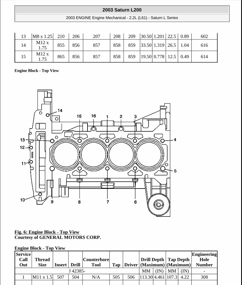
Engine Block - Top View
Fig. 6: Engine Block - Top View Courtesy of GENERAL MOTORS CORP.
Engine Block - Top View
13 M8 x 1.25 210 206 207 208 209 30.50 1.201 22.5 0.89 602
14M12 x 1.75 855 856 857 858 859 33.50 1.319 26.5 1.04 616
15M12 x 1.75
865 856 857 858 859 19.50 0.778 12.5 0.49 614
Service Call Out
Thread Size Insert Drill
Counterbore Tool Tap Driver
Drill Depth (Maximum)
Tap Depth (Maximum)
Engineering Hole
NumberJ 42385- MM (IN) MM (IN) -
1 M11 x 1.5 507 504 N/A 505 506 113.30 4.461 107.3 4.22 308
2003 Saturn L200
2003 ENGINE Engine Mechanical - 2.2L (L61) - Saturn L Series
steve
Monday, May 09, 2011 12:51:59 PM Page 14 © 2006 Mitchell Repair Information Company, LLC.

Lower Crankcase - Front View
Fig. 7: Identifying Front Lower Crankcase Thread Sizes Courtesy of GENERAL MOTORS CORP.
Lower Crankcase - Front View
2M12 x 1.75
865 856 857 858 859 13.50 0.531 12.5 0.49 317
3 M11 x 1.5 507 504 N/A 505 506 113.30 4.461 107.3 4.22 3094 M11 x 1.5 507 504 N/A 505 506 113.30 4.461 107.3 4.22 3105 M11 x 1.5 507 504 N/A 505 506 113.30 4.461 107.3 4.22 3026 M11 x 1.5 507 504 N/A 505 506 113.30 4.461 107.3 4.22 3057 M11 x 1.5 507 504 N/A 505 506 113.30 4.461 107.3 4.22 3048 M11 x 1.5 507 504 N/A 505 506 113.30 4.461 107.3 4.22 3039 M11 x 1.5 507 504 N/A 505 506 113.30 4.461 107.3 4.22 30110 M8 x 1.25 210 206 207 208 209 23.50 0.925 18.5 0.73 31311 M8 x 1.25 210 206 207 208 209 23.50 0.925 18.5 0.73 31112 M8 x 1.25 210 206 207 208 209 23.50 0.925 18.5 0.73 31213 M11 x 1.5 507 504 N/A 505 506 113.30 4.461 107.3 4.22 30614 M8 x 1.25 210 206 207 208 209 23.50 0.925 18.5 0.73 31415 M11 x 1.5 507 504 N/A 505 506 113.30 4.461 107.3 4.22 307
16M12 x 1.75
865 856 857 858 859 13.50 0.531 12.5 0.49 316
Service Call Out
Thread Size Insert Drill
Counterbore Tool Tap Driver
Drill Depth (Maximum)
Tap Depth (Maximum)
Engineering Hole
NumberJ 42385- MM (IN) MM (IN) -
1 M8 x 1.25 210 206 207 208 209 23.50 0.925 18.5 0.73 1382 M8 x 1.25 210 206 207 208 209 30.50 1.201 25.5 1.00 139
2003 Saturn L200
2003 ENGINE Engine Mechanical - 2.2L (L61) - Saturn L Series
steve
Monday, May 09, 2011 12:51:59 PM Page 15 © 2006 Mitchell Repair Information Company, LLC.

Lower Crankcase - Back View
Fig. 8: Identifying Rear Lower Crankcase Thread Sizes Courtesy of GENERAL MOTORS CORP.
Lower Crankcase - Back View
Lower Crankcase - Bottom View
3 M8 x 1.25 210 206 207 208 209 30.50 1.201 25.5 1.00 1404 M8 x 1.25 210 206 207 208 209 23.50 0.925 18.5 0.73 141
Service Call Out
Thread Size Insert Drill
Counterbore Tool Tap Driver
Drill Depth (Maximum)
Tap Depth (Maximum)
Engineering Hole
NumberJ 42385- MM (IN) MM (IN) -
1 M10 x 1.5 215 211 212 213 214 29.50 1.161 THRU 207
2003 Saturn L200
2003 ENGINE Engine Mechanical - 2.2L (L61) - Saturn L Series
steve
Monday, May 09, 2011 12:51:59 PM Page 16 © 2006 Mitchell Repair Information Company, LLC.

Fig. 9: Identifying Lower Bottom Crankcase Thread Sizes Courtesy of GENERAL MOTORS CORP.
Lower Crankcase - Bottom View Service
Call Out
Thread Size Insert Drill
Counterbore Tool Tap Driver
Drill Depth (Maximum)
Tap Depth (Maximum)
Engineering Hole
NumberJ 42385- MM (IN) MM (IN) -
1 M8 x 1.25 210 206 207 208 209 23.50 0.925 18.5 0.73 4152 M8 x 1.25 210 206 207 208 209 23.50 0.925 18.5 0.73 4163 M8 x 1.25 210 206 207 208 209 23.50 0.925 18.5 0.73 4174 M8 x 1.25 210 206 207 208 209 23.50 0.925 18.5 0.73 4185 M8 x 1.25 210 206 207 208 209 23.50 0.925 18.5 0.73 4196 M8 x 1.25 210 206 207 208 209 23.50 0.925 18.5 0.73 4057 M8 x 1.25 210 206 207 208 209 23.50 0.925 18.5 0.73 4068 M8 x 1.25 210 206 207 208 209 23.50 0.925 18.5 0.73 4079 M8 x 1.25 210 206 207 208 209 23.50 0.925 18.5 0.73 40810 M8 x 1.25 210 206 207 208 209 23.50 0.925 18.5 0.73 40911 M8 x 1.25 210 206 207 208 209 23.50 0.925 18.5 0.73 410
2003 Saturn L200
2003 ENGINE Engine Mechanical - 2.2L (L61) - Saturn L Series
steve
Monday, May 09, 2011 12:52:00 PM Page 17 © 2006 Mitchell Repair Information Company, LLC.
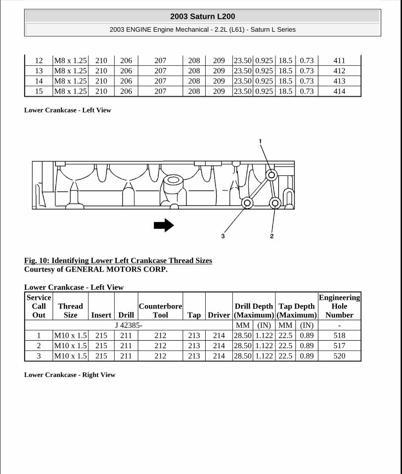
Lower Crankcase - Left View
Fig. 10: Identifying Lower Left Crankcase Thread Sizes Courtesy of GENERAL MOTORS CORP.
Lower Crankcase - Left View
Lower Crankcase - Right View
12 M8 x 1.25 210 206 207 208 209 23.50 0.925 18.5 0.73 41113 M8 x 1.25 210 206 207 208 209 23.50 0.925 18.5 0.73 41214 M8 x 1.25 210 206 207 208 209 23.50 0.925 18.5 0.73 41315 M8 x 1.25 210 206 207 208 209 23.50 0.925 18.5 0.73 414
Service Call Out
Thread Size Insert Drill
Counterbore Tool Tap Driver
Drill Depth (Maximum)
Tap Depth (Maximum)
Engineering Hole
NumberJ 42385- MM (IN) MM (IN) -
1 M10 x 1.5 215 211 212 213 214 28.50 1.122 22.5 0.89 5182 M10 x 1.5 215 211 212 213 214 28.50 1.122 22.5 0.89 5173 M10 x 1.5 215 211 212 213 214 28.50 1.122 22.5 0.89 520
2003 Saturn L200
2003 ENGINE Engine Mechanical - 2.2L (L61) - Saturn L Series
steve
Monday, May 09, 2011 12:52:00 PM Page 18 © 2006 Mitchell Repair Information Company, LLC.

Fig. 11: Identifying Lower Right Crankcase Thread Sizes Courtesy of GENERAL MOTORS CORP.
Lower Crankcase - Right View
Cylinder Head - Top View
Service Call Out
Thread Size Insert Drill
Counterbore Tool Tap Driver
Drill Depth (Maximum)
Tap Depth (Maximum)
Engineering Hole
NumberJ 42385- MM (IN) MM (IN) -
1 M8 x 1.25
210 211 212 213 214 30.50 1.201 22.5 0.886 615
2003 Saturn L200
2003 ENGINE Engine Mechanical - 2.2L (L61) - Saturn L Series
steve
Monday, May 09, 2011 12:52:00 PM Page 19 © 2006 Mitchell Repair Information Company, LLC.

Fig. 12: Cylinder Head - Top View Courtesy of GENERAL MOTORS CORP.
Cylinder Head - Top View Service
Call Out
Thread Size Insert Drill
Counterbore Tool Tap Driver
Drill Depth (Maximum)
Tap Depth (Maximum)
Engineering Hole
NumberJ 42385- MM (IN) MM (IN) -
1 M6 x 1.0 205 852 N/A 203 204 24 0.945 20 0.787 25152 M6 x 1.0 205 852 N/A 203 204 24 0.945 20 0.787 25143 M6 x 1.0 205 201 202 203 204 20 0.787 16 0.630 28124 M6 x 1.0 205 201 202 203 204 20 0.787 16 0.630 28205 M6 x 1.0 205 201 202 203 204 20 0.787 16 0.630 27106 M6 x 1.0 205 852 N/A 203 204 24 0.945 20 0.787 25137 M6 x 1.0 205 852 N/A 203 204 24 0.945 20 0.787 2512
8 M8 x 1.25854 No
Flange206 207 208 209 THRU THRU 2980
9 M6 x 1.0 205 201 202 203 204 20 0.787 16 0.630 281110 M6 x 1.0 205 201 202 203 204 20 0.787 16 0.630 281011 M6 x 1.0 205 852 N/A 203 204 24 0.945 20 0.787 251012 M6 x 1.0 205 852 N/A 203 204 24 0.945 20 0.787 251113 M6 x 1.0 205 201 202 203 204 16 0.630 THRU 291014 M6 x 1.0 205 201 202 203 204 16 0.630 THRU 2911
2003 Saturn L200
2003 ENGINE Engine Mechanical - 2.2L (L61) - Saturn L Series
steve
Monday, May 09, 2011 12:52:00 PM Page 20 © 2006 Mitchell Repair Information Company, LLC.

Cylinder Head - Intake Manifold Deck View
15 M6 x 1.0 205 852 N/A 203 204 24 0.945 20 0.787 252016 M6 x 1.0 205 852 N/A 203 204 24 0.945 20 0.787 252117 M6 x 1.0 205 201 202 203 204 20 0.787 16 0.630 281518 M6 x 1.0 205 201 202 203 204 20 0.787 16 0.630 281619 M6 x 1.0 205 852 N/A 203 204 24 0.945 20 0.787 252320 M6 x 1.0 205 852 N/A 203 204 24 0.945 20 0.787 252221 M6 x 1.0 205 201 202 203 204 20 0.787 16 0.630 281722 M6 x 1.0 205 852 N/A 203 204 24 0.945 20 0.787 252523 M6 x 1.0 205 852 N/A 203 204 24 0.945 20 0.787 252424 M6 x 1.0 205 201 202 203 204 20 0.787 16 0.630 282125 M6 x 1.0 205 852 N/A 203 204 24 0.945 20 0.787 252726 M6 x 1.0 205 852 N/A 203 204 24 0.945 20 0.787 252627 M6 x 1.0 205 201 202 203 204 20 0.787 16 0.630 281828 M6 x 1.0 205 201 202 203 204 20 0.787 16 0.630 282229 M6 x 1.0 205 852 N/A 203 204 24 0.945 20 0.787 252930 M6 x 1.0 205 852 N/A 203 204 24 0.945 20 0.787 252831 M6 x 1.0 205 201 202 203 204 20 0.787 16 0.630 281932 M6 x 1.0 205 201 202 203 204 20 0.787 16 0.630 282333 M8 x 1.25 210 206 207 208 209 25 0.984 20 0.787 262134 M8 x 1.25 210 206 207 208 209 25 0.984 20 0.787 2622
35 M8 x 1.25854 No
Flange853 N/A 208 209 25 0.984 20 0.787 2541
36 M8 x 1.25854 No
Flange853 N/A 208 209 25 0.984 20 0.787 2540
37 M6 x 1.0 210 206 207 208 209 20 0.787 16 0.630 281438 M6 x 1.0 205 852 N/A 203 204 24 0.945 20 0.787 251939 M6 x 1.0 205 852 N/A 203 204 24 0.945 20 0.787 251840 M6 x 1.0 210 206 207 208 209 20 0.787 16 0.630 271141 M6 x 1.0 210 206 207 208 209 20 0.787 16 0.630 281342 M6 x 1.0 205 852 N/A 203 204 24 0.945 20 0.787 251743 M6 x 1.0 205 852 N/A 203 204 24 0.945 20 0.787 2516
2003 Saturn L200
2003 ENGINE Engine Mechanical - 2.2L (L61) - Saturn L Series
steve
Monday, May 09, 2011 12:52:00 PM Page 21 © 2006 Mitchell Repair Information Company, LLC.

Fig. 13: Cylinder Head - Intake Manifold Deck View Courtesy of GENERAL MOTORS CORP.
Cylinder Head - Intake Manifold Deck View
Cylinder Head - Exhaust Manifold Deck View
Service Call Out
Thread Size Insert Drill
Counterbore Tool Tap Driver
Drill Depth (Maximum)
Tap Depth (Maximum)
Engineering Hole
NumberJ 42385- MM (IN) MM (IN) -
1 M6 x 1.0 205 201 202 203 204 20 0.787 16 0.630 41172 M6 x 1.0 205 201 202 203 204 20 0.787 16 0.630 41163 M6 x 1.0 205 201 202 203 204 20 0.787 16 0.630 41154 M6 x 1.0 205 201 202 203 204 20 0.787 16 0.630 41145 M6 x 1.0 205 201 202 203 204 20 0.787 16 0.630 41136 M6 x 1.0 205 201 202 203 204 20 0.787 16 0.630 41127 M6 x 1.0 205 201 202 203 204 20 0.787 16 0.630 41118 M6 x 1.0 205 201 202 203 204 20 0.787 16 0.630 41109 M6 x 1.0 205 201 202 203 204 20 0.787 16 0.630 4118
2003 Saturn L200
2003 ENGINE Engine Mechanical - 2.2L (L61) - Saturn L Series
steve
Monday, May 09, 2011 12:52:00 PM Page 22 © 2006 Mitchell Repair Information Company, LLC.
Fig. 14: Cylinder Head - Exhaust Manifold Deck View Courtesy of GENERAL MOTORS CORP.
Cylinder Head - Exhaust Manifold Deck View
Cylinder Head - Front View
Service Call Out
Thread Size Insert Drill
Counterbore Tool Tap Driver
Drill Depth (Maximum)
Tap Depth (Maximum)
Engineering Hole
NumberJ 42385- MM (IN) MM (IN) -
1 M8 x 1.25 210 206 207 208 209 25 0.984 20 0.78 31182 M8 x 1.25 210 206 207 208 209 25 0.984 20 0.78 31193 M8 x 1.25 210 206 207 208 209 25 0.984 20 0.78 32104 M27 x 2.0 N/A N/A N/A N/A N/A THRU 12 0.78 38105 M8 x 1.25 210 206 207 208 209 25 0.984 20 0.78 31106 M8 x 1.25 210 206 207 208 209 25 0.984 20 0.78 31117 M8 x 1.25 210 206 207 208 209 25 0.984 20 0.78 31128 M8 x 1.25 210 206 207 208 209 25 0.984 20 0.78 31139 M8 x 1.25 210 206 207 208 209 25 0.984 20 0.78 311410 M8 x 1.25 210 206 207 208 209 25 0.984 20 0.78 311511 M6 x 1.0 205 201 202 203 204 20 0.78 16 0.630 331012 M8 x 1.25 210 206 207 208 209 25 0.984 20 0.78 311613 M8 x 1.25 210 206 207 208 209 25 0.984 20 0.78 361014 M8 x 1.25 210 206 207 208 209 25 0.984 20 0.78 3117
2003 Saturn L200
2003 ENGINE Engine Mechanical - 2.2L (L61) - Saturn L Series
steve
Monday, May 09, 2011 12:52:00 PM Page 23 © 2006 Mitchell Repair Information Company, LLC.

Fig. 15: Cylinder Head - Front View Courtesy of GENERAL MOTORS CORP.
Cylinder Head - Front View
Cylinder Head - Back View
Service Call Out
Thread Size Insert Drill
Counterbore Tool Tap Driver
Drill Depth (Maximum)
Tap Depth (Maximum)
Engineering Hole
NumberJ 42385- MM (IN) MM (IN) -
1 M8 x 1.25 210 206 207 208 209 25 0.984 20 0.787 63102 M6 x 1.0 205 201 202 203 204 20 0.787 16 0.630 6210
2003 Saturn L200
2003 ENGINE Engine Mechanical - 2.2L (L61) - Saturn L Series
steve
Monday, May 09, 2011 12:52:00 PM Page 24 © 2006 Mitchell Repair Information Company, LLC.

Fig. 16: Cylinder Head - Back View Courtesy of GENERAL MOTORS CORP.
Cylinder Head - Back View Service
Call Out
Thread Size Insert Drill
Counterbore Tool Tap Driver
Drill Depth (Maximum)
Tap Depth (Maximum)
Engineering Hole
NumberJ 42385- MM (IN) MM (IN) -
1 M12 x 1.75
865 856 857 858 859 17 0.670 14 0.551 5011
2M12 x 1.75 865 856 857 858 859 17 0.670 14 0.551 5010
3 M8 x 1.25 210 206 207 208 209 25 0.984 20 0.787 50314 M8 x 1.25 210 206 207 208 209 25 0.984 20 0.787 5030
5M12 x 1.75 865 856 857 858 859 17 0.670 14 0.551 5310
6M12 x 1.75
865 856 857 858 859 17 0.670 14 0.551 5020
7 M8 x 1.25 210 206 207 208 209 25 0.984 THRU 5111
8 M8 x 1.25854 No
Flange206 207 208 209 25 0.984 THRU 5110
2003 Saturn L200
2003 ENGINE Engine Mechanical - 2.2L (L61) - Saturn L Series
steve
Monday, May 09, 2011 12:52:00 PM Page 25 © 2006 Mitchell Repair Information Company, LLC.

Note: 1, 2, 5, 6 holes are oil passages.
Cylinder Head - Bottom View
Fig. 17: Cylinder Head - Bottom View Courtesy of GENERAL MOTORS CORP.
Cylinder Head - Bottom View
COMPONENT LOCATOR
DISASSEMBLED VIEWS
Service Call Out
Thread Size Insert Drill
Counterbore Tool Tap Driver
Drill Depth (Maximum)
Tap Depth (Maximum)
Engineering Hole
NumberJ 42385- MM (IN) MM (IN) -
1M12 x 1.75
865 856 857 858 859 17 0.670 14 0.551 1510
2 N/A N/A N/A N/A N/A N/A N/A N/A N/A N/A 12133 N/A N/A N/A N/A N/A N/A N/A N/A N/A N/A 12124 N/A N/A N/A N/A N/A N/A N/A N/A N/A N/A 12115 N/A N/A N/A N/A N/A N/A N/A N/A N/A N/A 1210
2003 Saturn L200
2003 ENGINE Engine Mechanical - 2.2L (L61) - Saturn L Series
steve
Monday, May 09, 2011 12:52:00 PM Page 26 © 2006 Mitchell Repair Information Company, LLC.

Fig. 18: Cylinder Head and Components Courtesy of GENERAL MOTORS CORP.
Callouts For Fig. 18 Callout Component Name
1 Engine Oil Fill Cap2 Ignition Module and Coil Housing Assembly Bolt3 Ignition Module and Coil Housing Assembly4 Camshaft Cover5 Camshaft Cover Gasket
2003 Saturn L200
2003 ENGINE Engine Mechanical - 2.2L (L61) - Saturn L Series
steve
Monday, May 09, 2011 12:52:00 PM Page 27 © 2006 Mitchell Repair Information Company, LLC.

6 Camshaft Bearing Cap Bolt7 Camshaft Bearing Cap8 Fuel Rail Assembly Bolt9 Fuel Line Assembly10 Injector Wiring Harness11 Fuel Rail Assembly (with Fuel Injectors)12 Cylinder Head13 Front Engine Lift Bracket14 Engine Lift Bracket Bolt15 Cylinder Head Bolt16 Oil Flow Check Valve17 Exhaust Manifold Stud18 Exhaust Valve19 Intake Valve20 Camshaft Cover Grounding Strap Bolt21 Cylinder Head Oil Passage Plug22 Cylinder Head Oil Passage Plug23 Spark Plug24 Valve Stem Seal25 Valve Spring26 Valve Spring Retainer27 Valve Keys28 Hydraulic Lash Adjuster29 Roller Finger Follower30 Rear Engine Lift Bracket Bolt31 Rear Engine Lift Bracket32 EGR Port Cover Gasket33 EGR Port Cover34 EGR Port Cover Bolt35 Camshaft Bearing Cap36 Camshaft Bearing Cap Bolt37 Camshaft Bearing Cap38 Camshaft Bearing Cap Bolt39 Exhaust Camshaft40 Intake Camshaft41 Camshaft Cover Grounding Strap42 Camshaft Cover Grounding Strap Bolt43 Camshaft Cover Bolt
2003 Saturn L200
2003 ENGINE Engine Mechanical - 2.2L (L61) - Saturn L Series
steve
Monday, May 09, 2011 12:52:00 PM Page 28 © 2006 Mitchell Repair Information Company, LLC.
Fig. 19: Engine Block and Components Courtesy of GENERAL MOTORS CORP.
Callouts For Fig. 19
2003 Saturn L200
2003 ENGINE Engine Mechanical - 2.2L (L61) - Saturn L Series
steve
Monday, May 09, 2011 12:52:00 PM Page 29 © 2006 Mitchell Repair Information Company, LLC.

Callout Component Name1 Thermostat Housing2 Thermostat Housing to Engine Block Seal3 Water Transfer Pipe4 Water Transfer Pipe to Water Pump Seal5 Water Pump Bolt6 Water Pump7 Water Pump to Engine Block Seal8 Water Pump Bolt9 Oil Filter Cap10 Oil Filter11 Oil Filter to Engine Block Seal12 Cylinder Head Alignment Pin13 Intake Balance Shaft Rear Bearing14 Intake Balance Shaft15 Intake Balance Shaft Bearing Carrier16 Intake Balance Shaft Drive Sprocket17 Intake Balance Shaft Drive Sprocket Bolt18 Exhaust Balance Shaft Drive Sprocket Bolt19 Exhaust Balance Shaft Drive Sprocket20 Exhaust Balance Shaft Bearing Carrier Bolt21 Exhaust Balance Shaft22 Exhaust Balance Shaft Rear Bearing Engine23 Front Cover Alignment Pin24 Engine Oil Passage Plug25 Engine Oil Passage Plug26 Top Compression Piston Ring27 Second Compression Piston Ring28 Piston Oil Ring Assembly29 Piston30 Piston Pin31 Piston Pin Retainer32 Connecting Rod33 Connecting Rod Cap Bolt34 Connecting Rod Bearing35 Crankshaft Thrust Bearing36 Crankshaft Bearing37 Crankshaft Damper Alignment Key38 Crankshaft39 Crankshaft Rear Seal40 Starter Ring Gear
2003 Saturn L200
2003 ENGINE Engine Mechanical - 2.2L (L61) - Saturn L Series
steve
Monday, May 09, 2011 12:52:00 PM Page 30 © 2006 Mitchell Repair Information Company, LLC.

Flywheel42 Flywheel to Crankshaft Bolt43 Engine Oil Pan Baffle44 Engine Oil Pan45 Pan Drain Plug46 Engine Oil Pan Nut47 Engine Oil Pan Stud48 Engine Oil Pan Bolt49 Engine Oil Pickup50 Lower Crankcase to Engine Block Bolt51 Lower Crankcase to Engine Block Bolt52 Crankshaft Bearing Bolt53 Lower Crankcase to Engine Block Bolt54 Lower Crankcase55 Lower Crankcase Alignment Pin56 Lower Crankcase Alignment Pin57 Engine Block58 Water Jacket Plug59 Engine Block to Transmission Alignment Pin60 Cylinder Head to Engine Block Bolt61 Water Jacket Drain Plug62 Water Pump to Engine Block Bolt63 Thermostat Housing to Engine Block Bolt64 Thermostat Housing to Engine Block Bolt65 Thermostat Gasket66 Thermostat
2003 Saturn L200
2003 ENGINE Engine Mechanical - 2.2L (L61) - Saturn L Series
steve
Monday, May 09, 2011 12:52:00 PM Page 31 © 2006 Mitchell Repair Information Company, LLC.

Fig. 20: Timing Chain and Components Courtesy of GENERAL MOTORS CORP.
Callouts For Fig. 20 Callout Component Name
1 Upper Timing Chain Guide Bolt2 Upper Timing Chain Guide3 Timing Chain4 Intake Camshaft Sprocket5 Intake Camshaft Sprocket to Camshaft Bolt6 Fixed Timing Chain Guide Bolt7 Fixed Timing Chain Guide8 Fixed Timing Chain Guide Bolt9 Oil Pump Cover Bolt10 Oil Pump Cover11 Oil Pump Inner Gerotor12 Oil Pump Outer Gerotor13 Engine Front Cover Gasket14 Engine Front Cover15 Engine Front Cover Access Plate Bolt16 Front Crankshaft Seal17 Crankshaft Damper
2003 Saturn L200
2003 ENGINE Engine Mechanical - 2.2L (L61) - Saturn L Series
steve
Monday, May 09, 2011 12:52:00 PM Page 32 © 2006 Mitchell Repair Information Company, LLC.

18 Crankshaft Damper Bolt19 Engine Front Cover Bolt20 Oil Pressure Relief Valve Plunger21 Oil Pressure Relieve Valve Spring22 Oil Pressure Relief Valve Plug23 Crankshaft Sprocket Alignment Key24 Timing Chain Oil Nozzle25 Exhaust Camshaft Sprocket to Camshaft Bolt26 Timing Chain Drive Sprocket27 Adjustable Timing Chain Guide Bolt28 Adjustable Timing Chain Guide29 Timing Chain Tensioner Seal30 Timing Chain Tensioner31 Drive Chain Guide Bolt32 Balance Shaft Drive Chain Guide33 Balance Shaft Drive Sprocket34 Adjustable Balance Shaft Drive Chain Guide Bolt35 Adjustable Balance Shaft Drive Chain Guide36 Balance Shaft Drive Chain Tensioner Assembly37 Water Pump38 Water Pump Drive Sprocket Bolt39 Balance Shaft Drive Chain Guide40 Balance Shaft Drive Chain Guide Bolt41 Engine Front Cover Access Plate Seal42 Engine Front Cover Access Plate
2003 Saturn L200
2003 ENGINE Engine Mechanical - 2.2L (L61) - Saturn L Series
steve
Monday, May 09, 2011 12:52:00 PM Page 33 © 2006 Mitchell Repair Information Company, LLC.

Fig. 21: Intake Manifold and Components Courtesy of GENERAL MOTORS CORP.
Callouts For Fig. 21
2003 Saturn L200
2003 ENGINE Engine Mechanical - 2.2L (L61) - Saturn L Series
steve
Monday, May 09, 2011 12:52:00 PM Page 34 © 2006 Mitchell Repair Information Company, LLC.
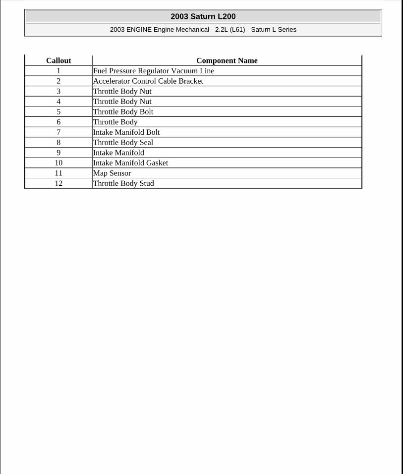
Callout Component Name1 Fuel Pressure Regulator Vacuum Line2 Accelerator Control Cable Bracket3 Throttle Body Nut4 Throttle Body Nut5 Throttle Body Bolt6 Throttle Body7 Intake Manifold Bolt8 Throttle Body Seal9 Intake Manifold10 Intake Manifold Gasket11 Map Sensor12 Throttle Body Stud
2003 Saturn L200
2003 ENGINE Engine Mechanical - 2.2L (L61) - Saturn L Series
steve
Monday, May 09, 2011 12:52:00 PM Page 35 © 2006 Mitchell Repair Information Company, LLC.

2003 Saturn L200
2003 ENGINE Engine Mechanical - 2.2L (L61) - Saturn L Series
steve
Monday, May 09, 2011 12:52:00 PM Page 36 © 2006 Mitchell Repair Information Company, LLC.
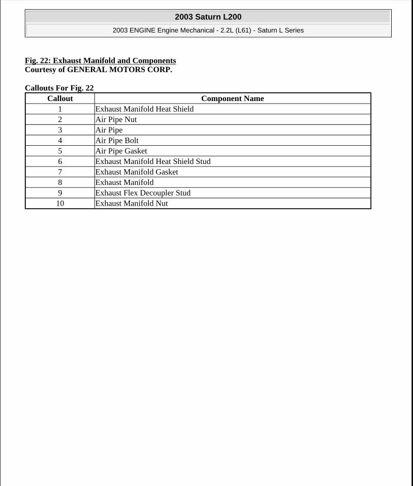
Fig. 22: Exhaust Manifold and ComponentsCourtesy of GENERAL MOTORS CORP.
Callouts For Fig. 22 Callout Component Name
1 Exhaust Manifold Heat Shield2 Air Pipe Nut3 Air Pipe4 Air Pipe Bolt5 Air Pipe Gasket6 Exhaust Manifold Heat Shield Stud7 Exhaust Manifold Gasket8 Exhaust Manifold9 Exhaust Flex Decoupler Stud10 Exhaust Manifold Nut
2003 Saturn L200
2003 ENGINE Engine Mechanical - 2.2L (L61) - Saturn L Series
steve
Monday, May 09, 2011 12:52:00 PM Page 37 © 2006 Mitchell Repair Information Company, LLC.

Fig. 23: Accessory and Engine Drive Belt Components Courtesy of GENERAL MOTORS CORP.
Callouts For Fig. 23 Callout Component Name
2003 Saturn L200
2003 ENGINE Engine Mechanical - 2.2L (L61) - Saturn L Series
steve
Monday, May 09, 2011 12:52:00 PM Page 38 © 2006 Mitchell Repair Information Company, LLC.

DIAGNOSTIC INFORMATION AND PROCEDURES
DRIVE BELT AND TENSIONER COMPLAINT/CONDITION CHART
Drive Belt and Tensioner Complaint/Condition Chart
1 Power Steering Pump2 Power Steering Pressure Line3 Generator Bolt4 Generator Pulley5 Accessory Drive Belt6 Air Compressor Bolt7 Air Conditioning Compressor8 Accessory Drive Belt Tensioner Bolt9 Accessory Drive Belt Tensioner10 Generator Assembly11 Starter Assembly12 Power Steering Pump Bolt13 Starter Assembly to Engine Block Bolt
Complaint/Condition Possible Cause(s) Correction(s)
Tension too High
Wrong belt. Belt routing and alignment on pulleys.
Replace belt, check belt, and pulleys for proper belt installation and alignment in grooves.
Wrong pulley.Check pulley diameters against another vehicle or good parts.
Tensioner inoperative. Replace tensioner.
Tension too Low
Wrong belt. Replace belt.Worn belt. Replace belt.Tensioner inoperative or broken internal spring.
Replace tensioner. (Do not attempt to repair)
Wrong pulley.Check pulley diameters against another vehicle or good parts.
Belt Chirp
Wrong belt. Check belt tension.Belt misaligned. Check pulley alignment.
Belt installed incorrectly. Check for belt alignment in grooves.
Tensioner inoperative. Check belt tensioner motion.Tensioner partially seized. Check tensioner movement.Tensioner inoperative. Check belt tension.
Tensioner/idler pulley bearing.Check tensioner/idler pulley bearings.
Tensioner inoperative. Check belt tension.
2003 Saturn L200
2003 ENGINE Engine Mechanical - 2.2L (L61) - Saturn L Series
steve
Monday, May 09, 2011 12:52:00 PM Page 39 © 2006 Mitchell Repair Information Company, LLC.

DIAGNOSTIC STARTING POINT - ENGINE MECHANICAL
Begin the system diagnosis by reviewing the Disassembled Views, Engine Component Description, Lubrication Description, and New Product Information in Engine Unit Repair. Reviewing the description and operation information will help you determine the correct symptom diagnostic procedure when a malfunction exists. Reviewing the description and operation information will also help you determine if the condition described by the customer is normal operation. Refer to Symptoms - Engine Mechanical in order to identify the correct procedure for diagnosing the system and where the procedure is located.
SYMPTOMS - ENGINE MECHANICAL
Strategy Based Diagnostics
1. Perform the DIAGNOSTIC STARTING POINT -- ENGINE CONTROLS in Self-Diagnostics - 2.2L in Engine Performance before using the symptom tables, if applicable.
2. Review the system operations in order to familiarize yourself with the system functions. Refer to Disassembled Views, Engine Component Description, and Lubrication Description in Engine Unit
Intermittent Squeal or Whistle Noise Notice: Diagnosis is difficult. Requires accessory drive belt removal and engine cold starts to validate concern. Do not run engine for more than 3 minutes with accessory drive belt off.
Tensioner/idler pulley bearing.Check tensioner/idler pulley bearings.
Wrong belt. Check for proper belt.
Worn belt.Inspect belt for wear and check tension.
Excessive pulley radial/axial runout.
Replace pulley.
Belt misaligned. Check pulley alignment.Water pump, power steering pump, generator, A/C compressor, tensioner or idler bearing/loads.
Check all accessories for bearing/component seizure.
Oil pump pressure regulator.Replace oil pump pressure regulator valve.
Accessory Drive Growl with A/C On During Acceleration and/or Growl from Belt Tensioner.
Belt tensioner (internal).
IMPORTANT:
Do not disassemble the belt tensioner. Check belt tensioner movement.
Check belt tension.
Water pump, power steering pump, generator, A/C compressor, tensioner, or idler bearing.
Replace faulty component.
Hoot or Growl Noise Idler pulley bearing. Replace idler pulley bearing.
IMPORTANT: Saturn service tool SA9217NE Chassis Ear Tool (or equivalent) should be used to locate source(s) of noises caused by vibration(s).
2003 Saturn L200
2003 ENGINE Engine Mechanical - 2.2L (L61) - Saturn L Series
steve
Monday, May 09, 2011 12:52:00 PM Page 40 © 2006 Mitchell Repair Information Company, LLC.
Repair.
All diagnosis on a vehicle should follow a logical process. Strategy based diagnostics is a uniform approach for repairing all systems. The diagnostic flow may always be used in order to resolve a system condition. The diagnostic flow is the place to start when repairs are necessary.
Visual/Physical Inspection
Inspect for aftermarket devices which could affect the operation of the engine.
Inspect the easily accessible or visible system components for obvious damage or conditions which could cause the symptom.
Check for the correct oil level, proper oil viscosity, and correct filter application.
Verify the exact operating conditions under which the concern exists. Note factors such as engine RPM, ambient temperature, engine temperature, amount of engine warm-up time, and other specifics.
Compare the engine sounds, if applicable, to a known good engine and make sure you are not trying to correct a normal condition.
Intermittent
Test the vehicle under the same conditions that the customer reported in order to verify the system is operating properly.
Symptom List
Refer to a symptom diagnostic procedure from the following list in order to diagnose the symptom:
Base Engine Misfire without Internal Engine Noises
Base Engine Misfire with Abnormal Internal Lower Engine Noises
Base Engine Misfire with Abnormal Valve Train Noise
Base Engine Misfire with Coolant Consumption
Base Engine Misfire with Excessive Oil Consumption
Engine Compression Test
Engine Noise on Start-Up, but Only Lasting a Few Seconds
Upper Engine Noise, Regardless of Engine Speed
Lower Engine Noise, Regardless of Engine Speed
Engine Noise Under Load
Engine Will Not Crank - Crankshaft Will Not Rotate
Oil Consumption Diagnosis
Oil Pressure Diagnosis and Testing
Oil Leak Diagnosis
Coolant in Combustion Chamber
Coolant in Engine Oil
2003 Saturn L200
2003 ENGINE Engine Mechanical - 2.2L (L61) - Saturn L Series
steve
Monday, May 09, 2011 12:52:00 PM Page 41 © 2006 Mitchell Repair Information Company, LLC.
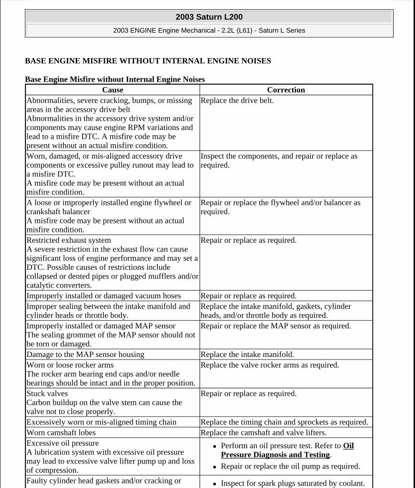
BASE ENGINE MISFIRE WITHOUT INTERNAL ENGINE NOISES
Base Engine Misfire without Internal Engine Noises Cause Correction
Abnormalities, severe cracking, bumps, or missing areas in the accessory drive belt Abnormalities in the accessory drive system and/or components may cause engine RPM variations and lead to a misfire DTC. A misfire code may be present without an actual misfire condition.
Replace the drive belt.
Worn, damaged, or mis-aligned accessory drive components or excessive pulley runout may lead to a misfire DTC. A misfire code may be present without an actual misfire condition.
Inspect the components, and repair or replace as required.
A loose or improperly installed engine flywheel or crankshaft balancer A misfire code may be present without an actual misfire condition.
Repair or replace the flywheel and/or balancer as required.
Restricted exhaust system A severe restriction in the exhaust flow can cause significant loss of engine performance and may set a DTC. Possible causes of restrictions include collapsed or dented pipes or plugged mufflers and/or catalytic converters.
Repair or replace as required.
Improperly installed or damaged vacuum hoses Repair or replace as required.Improper sealing between the intake manifold and cylinder heads or throttle body.
Replace the intake manifold, gaskets, cylinder heads, and/or throttle body as required.
Improperly installed or damaged MAP sensor The sealing grommet of the MAP sensor should not be torn or damaged.
Repair or replace the MAP sensor as required.
Damage to the MAP sensor housing Replace the intake manifold.Worn or loose rocker arms The rocker arm bearing end caps and/or needle bearings should be intact and in the proper position.
Replace the valve rocker arms as required.
Stuck valves Carbon buildup on the valve stem can cause the valve not to close properly.
Repair or replace as required.
Excessively worn or mis-aligned timing chain Replace the timing chain and sprockets as required.Worn camshaft lobes Replace the camshaft and valve lifters.Excessive oil pressure A lubrication system with excessive oil pressure may lead to excessive valve lifter pump up and loss of compression.
Perform an oil pressure test. Refer to Oil Pressure Diagnosis and Testing.
Repair or replace the oil pump as required.
Faulty cylinder head gaskets and/or cracking or Inspect for spark plugs saturated by coolant.
2003 Saturn L200
2003 ENGINE Engine Mechanical - 2.2L (L61) - Saturn L Series
steve
Monday, May 09, 2011 12:52:00 PM Page 42 © 2006 Mitchell Repair Information Company, LLC.

BASE ENGINE MISFIRE WITH ABNORMAL INTERNAL LOWER ENGINE NOISES
Base Engine Misfire with Abnormal Internal Lower Engine Noises
other damage to the cylinder heads and engine block cooling system passages Coolant consumption may or may not cause the engine to overheat.
Inspect the cylinder heads, engine block, and/or head gaskets.
Repair or replace as required.
Worn piston rings Oil consumption may or may not cause the engine to misfire.
Inspect the spark plugs for oil deposits.
Inspect the cylinders for a loss of compression. Refer to Engine Compression Test.
Perform cylinder leak down and compression testing to identify the cause.
Repair or replace as required. A damaged crankshaft reluctor wheel A damaged crankshaft reluctor wheel can result in different symptoms depending on the severity and location of the damage.
Systems with electronic communications, DIS or coil per cylinder, and severe reluctor ring damage may exhibit periodic loss of crankshaft position, stop delivering a signal, and then re-sync the crankshaft position.
Systems with electronic communication, DIS or coil per cylinder, and slight reluctor ring damage may exhibit no loss of crankshaft position and no misfire may occur. However, a P0300 DTC may be set.
Systems with mechanical communications, high voltage switch, and severe reluctor ring damage may cause additional pulses and effect fuel and spark delivery to the point of generating a P0300 DTC or P0336.
Replace the sensor and/or crankshaft as required.
Cause CorrectionAbnormalities, severe cracking, bumps or missing areas in the accessory drive belt Abnormalities in the accessory drive system and/or components may cause engine RPM variations, noises similar to a faulty lower engine, and also lead to a misfire condition. A misfire code may be present without an actual misfire condition.
Replace the drive belt.
Worn, damaged, or mis-aligned accessory drive components or excessive pulley runout
Inspect the components, repair or replace as required.
2003 Saturn L200
2003 ENGINE Engine Mechanical - 2.2L (L61) - Saturn L Series
steve
Monday, May 09, 2011 12:52:00 PM Page 43 © 2006 Mitchell Repair Information Company, LLC.

BASE ENGINE MISFIRE WITH ABNORMAL VALVE TRAIN NOISE
Base Engine Misfire with Abnormal Valve Train Noise
BASE ENGINE MISFIRE WITH COOLANT CONSUMPTION
Base Engine Misfire with Coolant Consumption
A misfire code may be present without an actual misfire condition.Loose or improperly installed engine flywheel or crankshaft balancer A misfire code may be present without an actual misfire condition.
Repair or replace the flywheel and/or balancer as required.
Worn piston rings Oil consumption may or may not cause the engine to misfire.
Inspect the spark plugs for oil deposits.
Inspect the cylinders for a loss of compression. Refer to Engine Compression Test.
Perform cylinder leak down and compression testing to determine the cause.
Repair or replace as required. Worn crankshaft thrust bearings Severely worn thrust surfaces on the crankshaft and/or thrust bearing may permit fore and aft movement of the crankshaft, and create a DTC without an actual misfire condition.
Replace the crankshaft and bearings as required.
Cause CorrectionWorn or loose rocker arms The rocker arm bearing end caps and/or needle bearings should intact within the rocker arm assembly.
Replace the valve rocker arms as required.
Stuck valves Carbon buildup on the valve stem can cause the valve to not close properly.
Repair or replace as required.
Excessively worn or mis-aligned timing chain Replace the timing chain and sprockets as required.Worn camshaft lobes Replace the camshaft and valve lifters.Sticking lifters Replace as required.
Cause CorrectionFaulty cylinder head gaskets and/or cracking, or other damage to the cylinder heads and engine block cooling system passages. Coolant consumption may or may not cause the engine to overheat.
Inspect for spark plugs saturated by coolant.
Perform a cylinder leak down test.
Inspect the cylinder heads and engine block for damage to the coolant passages and/or a faulty head gasket.
2003 Saturn L200
2003 ENGINE Engine Mechanical - 2.2L (L61) - Saturn L Series
steve
Monday, May 09, 2011 12:52:00 PM Page 44 © 2006 Mitchell Repair Information Company, LLC.

BASE ENGINE MISFIRE WITH EXCESSIVE OIL CONSUMPTION
Base Engine Misfire with Excessive Oil Consumption
ENGINE NOISE ON START-UP, BUT ONLY LASTING A FEW SECONDS
Engine Noise on Start-Up, but Only Lasting a Few Seconds
UPPER ENGINE NOISE, REGARDLESS OF ENGINE SPEED
Upper Engine Noise, Regardless of Engine Speed
Repair or replace as required.
Cause CorrectionWorn valves, valve guides and/or valve stem oil seals
Inspect the spark plugs for oil deposits.
Repair or replace as required. Worn piston rings Oil consumption may or may not cause the engine to misfire.
Inspect the spark plugs for oil deposits.
Inspect the cylinders for a loss of compression. Refer to Engine Compression Test.
Perform cylinder leak down and compression testing to determine the cause.
Repair or replace as required.
Cause CorrectionIncorrect oil filter without anti-drainback feature Install the correct oil filter.Incorrect oil viscosity 1. Drain the oil.
2. Install the correct viscosity oil. High valve lifter leak down rate Replace the lifters as required.Worn crankshaft thrust bearing Inspect the thrust bearing and crankshaft.
Repair or replace as required. Damaged or faulty oil filter by-pass valve Inspect the oil filter by-pass valve for proper
operation.
Repair or replace as required.
Cause CorrectionLow oil pressure Perform an oil pressure test. Refer to Oil
Pressure Diagnosis and Testing.
Repair or replace as required. Loose and/or worn valve rocker arm attachments Inspect the valve rocker arm stud, nut or bolt.
Repair or replace as required. Worn valve rocker arm Replace the valve rocker arm.
2003 Saturn L200
2003 ENGINE Engine Mechanical - 2.2L (L61) - Saturn L Series
steve
Monday, May 09, 2011 12:52:00 PM Page 45 © 2006 Mitchell Repair Information Company, LLC.

LOWER ENGINE NOISE, REGARDLESS OF ENGINE SPEED
Lower Engine Noise, Regardless of Engine Speed
Improper lubrication to the valve rocker arms Inspect the following components, and repair or replace as required:
The valve rocker arm
The valve lifter
The oil filter bypass valve
The oil pump and pump screen
The engine block oil galleries Broken valve spring Replace the valve spring.Worn or dirty valve lifters Replace the valve lifters.Stretched or broken timing chain and/or damaged sprocket teeth
Replace the timing chain and sprockets.
Worn, damaged, or faulty timing chain tensioners Replace tensionersWorn engine camshaft lobes Inspect the engine camshaft lobes.
Replace the camshaft and valve lifters as required.
Worn valve guides or valve stems Inspect the following components, and repair as required:
The valves
The valve guides Stuck valves Carbon on the valve stem or valve seat may cause the valve to stay open.
Inspect the following components, and repair as required:
The valves
The valve guides
Cause CorrectionLow oil pressure Perform an oil pressure test. Refer to Oil
Pressure Diagnosis and Testing.
Repair or replace damaged components as required.
Worn accessory drive components Abnormalities, such as severe cracking, bumps, or missing areas in the accessory drive belt and/or misalignment of system components
Inspect the accessory drive system.
Repair or replace as required.
Loose or damaged crankshaft balancer Inspect the crankshaft balancer.
Repair or replace as required. Detonation or spark knock Verify the correct operation of the ignition system.
2003 Saturn L200
2003 ENGINE Engine Mechanical - 2.2L (L61) - Saturn L Series
steve
Monday, May 09, 2011 12:52:00 PM Page 46 © 2006 Mitchell Repair Information Company, LLC.

ENGINE NOISE UNDER LOAD
Engine Noise Under Load
Refer to DETONATION/SPARK KNOCK in Troubleshooting No Codes - 2.2L in Engine Performance.
Loose torque converter bolts Inspect the torque converter bolts and flywheel.
Repair or replace as required. Loose or damaged flywheel Repair or replace the flywheel.Damaged oil pan, contacting the oil pump screen An oil pan that has been damaged, may improperly position the oil pump screen, preventing proper oil flow to the oil pump.
Inspect the oil pan.
Inspect the oil pump screen.
Repair or replace as required.
Oil pump screen loose, damaged or restricted Inspect the oil pump screen.
Repair or replace as required. Worn or damaged balance shafts or bushings Inspect the balance shaft and bushings.
Replace as required. Excessive piston-to-cylinder bore clearance Inspect the piston and cylinder bore.
Repair as required. Excessive piston pin-to-bore clearance Inspect the piston, piston pin, and the
connecting rod.
Repair or replace as required. Excessive connecting rod bearing clearance Inspect the following components, and repair as
required:
The connecting rod bearings
The connecting rods
The crankshaft
The crankshaft journals Excessive crankshaft bearing clearance Inspect the following components, and repair as
required:
The crankshaft bearings
The crankshaft journals Incorrect piston, piston pin, and connecting rod installation Pistons must be installed with the mark or dimple on the top of the piston, facing the front of the engine. Piston pins must be centered in the connecting rod pin bore.
Verify the pistons, piston pins and connecting rods are installed correctly.
Repair as required.
2003 Saturn L200
2003 ENGINE Engine Mechanical - 2.2L (L61) - Saturn L Series
steve
Monday, May 09, 2011 12:52:00 PM Page 47 © 2006 Mitchell Repair Information Company, LLC.

ENGINE WILL NOT CRANK - CRANKSHAFT WILL NOT ROTATE
Engine Will Not Crank - Crankshaft Will Not Rotate
Cause CorrectionLow oil pressure Perform an oil pressure test. Refer to Oil
Pressure Diagnosis and Testing.
Repair or replace as required. Detonation or spark knock Verify the correct operation of the ignition. Refer to
DETONATION/SPARK KNOCK in Troubleshooting No Codes - 2.2L in Engine Performance.
Loose torque converter bolts Inspect the torque converter bolts and flywheel.
Repair as required. Cracked flywheel, automatic transmission Inspect the flywheel bolts and flywheel.
Repair as required. Excessive connecting rod bearing clearance Inspect the following components, and repair as
required:
The connecting rod bearings
The connecting rods
The crankshaft Excessive crankshaft bearing clearance Inspect the following components, and repair as
required:
The crankshaft bearings
The crankshaft journals
The cylinder block crankshaft bearing bore
Cause CorrectionSeized accessory drive system component 1. Remove accessory drive belts.
2. Rotate crankshaft by hand at the balancer or flywheel location.
Hydraulically locked cylinder
Coolant/antifreeze in cylinder
Oil in cylinder
Fuel in cylinder
1. Remove spark plugs and check for fluid.
2. Inspect for broken head gasket.
3. Inspect for cracked engine block or cylinder head.
4. Inspect for a sticking fuel injector.
5. Inspect for cracked cylinder wall. Seized automatic transmission torque converter 1. Remove the torque converter bolts.
2003 Saturn L200
2003 ENGINE Engine Mechanical - 2.2L (L61) - Saturn L Series
steve
Monday, May 09, 2011 12:52:00 PM Page 48 © 2006 Mitchell Repair Information Company, LLC.

COOLANT IN COMBUSTION CHAMBER
Coolant in Combustion Chamber
2. Rotate crankshaft by hand at the balancer or flywheel location.
Seized manual transmission 1. Disengage the clutch.
2. Rotate crankshaft by hand at the balancer or flywheel location.
Refer to Unit Repair Manual - Manual Transmission.
Broken timing chain and/or gears Inspect timing chain and gears.
Repair as required. Seized balance shaft Inspect balance shaft.
Repair as required. Material in cylinder
Broken valve
Piston material
Foreign material
Cracked cylinder wall
Inspect cylinder for damaged components and/or foreign materials.
Inspect for fallen cylinder wall.
Repair or replace as required.
Seized crankshaft or connecting rod bearings Inspect crankshaft and connecting rod bearings.
Inspect for fallen cylinder wall.
Repair as required. Bent or broken connecting rod Inspect connecting rods.
Repair as required. Broken crankshaft Inspect crankshaft.
Repair as required.
Cause Correction
DEFINITION: Excessive white smoke and/or coolant type odor coming from the exhaust pipe may indicate coolant in the combustion chamber. Low coolant levels, an inoperative cooling fan, or a faulty thermostat may lead to an "overtemperature" condition which may cause engine component damage.
1. A slower than normal cranking speed may indicate coolant entering the combustion chamber. Refer to Engine Will Not Crank - Crankshaft Will Not Rotate.
2. Remove the spark plugs and inspect for spark plugs saturated by coolant or coolant in the cylinder bore.
3. Inspect by performing a cylinder leak-down test. During this test, excessive air bubbles within the
2003 Saturn L200
2003 ENGINE Engine Mechanical - 2.2L (L61) - Saturn L Series
steve
Monday, May 09, 2011 12:52:00 PM Page 49 © 2006 Mitchell Repair Information Company, LLC.

COOLANT IN ENGINE OIL
Coolant in Engine Oil
ENGINE COMPRESSION TEST
Perform the following steps in order to conduct a compression test for the L61.
1. Conduct the following steps in order to check cylinder compression.
coolant may indicate a faulty gasket or damaged component.
4. Inspect by performing a cylinder compression test. Two cylinders "side-by-side" on the engine block, with low compression, may indicate a failed cylinder head gasket. Refer to Engine Compression Test.
Faulty cylinder head gasket Replace the head gasket and components as required. Refer to Cylinder Head Cleaning and Inspection and Cylinder Head Replacement.
Warped cylinder head Replace the cylinder head and gasket. Refer to Cylinder Head Cleaning and Inspection.
Cracked cylinder head Replace the cylinder head and gasket.Cracked cylinder sleeve Replace the components as required.Cylinder head or block porosity Replace the components as required.
Cause CorrectionDEFINITION: Foamy or discolored oil or an engine oil "overfill" condition may indicate coolant entering the engine crankcase. Low coolant levels, an inoperative cooling fan, or a faulty thermostat may lead to an "overtemperature" condition which may cause engine component damage. Contaminated engine oil and oil filter should be changed.
1. Inspect the oil for excessive foaming or an overfill condition. Oil diluted by coolant may not properly lubricate the crankshaft bearings and may lead to component damage. Refer to Lower Engine Noise, Regardless of Engine Speed.
2. Inspect by performing a cylinder leak-down test. During this test, excessive air bubbles within the cooling system may indicate a faulty gasket or damaged component.
3. Inspect by performing a cylinder compression test. Two cylinders "side-by-side" on the engine block with low compression may indicate a failed cylinder head gasket. Refer to Engine Compression Test.
Faulty cylinder head gasket Replace the head gasket and components as required. Refer to Cylinder Head Cleaning and Inspection and Cylinder Head Replacement.
Warped cylinder head Replace the cylinder head and gasket. Refer to Cylinder Head Cleaning and Inspection.
Cracked cylinder head Replace the cylinder head and gasket.Cracked cylinder sleeve Replace the components as required.Cylinder head or block porosity Replace the components as required.
2003 Saturn L200
2003 ENGINE Engine Mechanical - 2.2L (L61) - Saturn L Series
steve
Monday, May 09, 2011 12:52:00 PM Page 50 © 2006 Mitchell Repair Information Company, LLC.

1. Engine should be at room temperature.
2. Disconnect wiring from the ignition module.
3. Remove the spark plugs.
4. Throttle body valve should be wide open.
5. Battery should be at or near full charge.
2. For each cylinder, crank engine through four compression strokes.
3. The lowest reading cylinder should not be less than 70% of the highest.
4. No cylinder reading should be less than 689 kPa (100 psi).
Normal - Compression builds up quickly and evenly to specified compression on each cylinder.
Piston Rings - Compression low on first stroke. Tends to build up on following strokes but does not reach normal. Improves considerably with addition of oil.
Valves - Compression low on first stroke. Does not tend to build up on the following strokes. Does not improve much with the addition of oil. Use approximately three squirts from a plunger-type oiler.
CYLINDER LEAKAGE TEST
Tools Required
J 35667-A Cylinder Head Leakdown Tester or equivalent. See Special Tools and Equipment.
Worn or burnt valves
Broken valve springs
Stuck valve lifters
Incorrect valve lash/adjustment
Damaged piston
Worn piston rings
Worn or scored cylinder bore
Damaged cylinder head gasket
Cracked or damaged cylinder head
Cracked or damaged engine block
IMPORTANT: The results of a compression test will fall into the following categories:
IMPORTANT: A leakage test may be performed in order to measure cylinder/combustion chamber leakage. High leakage may indicate one or more of the following:
CAUTION: Refer to BATTERY DISCONNECT CAUTION in Cautions and Notices.
2003 Saturn L200
2003 ENGINE Engine Mechanical - 2.2L (L61) - Saturn L Series
steve
Monday, May 09, 2011 12:52:00 PM Page 51 © 2006 Mitchell Repair Information Company, LLC.

1. Disconnect the battery ground negative cable.
2. Remove the spark plugs. Refer to SPARK PLUGS - 2.2L in Removal and Installation in Engine Performance.
3. Rotate the crankshaft to place the piston in the cylinder being tested at Top Dead Center (TDC) of the compression stroke.
4. Install the J 35667-A or equivalent. See Special Tools and Equipment.
5. Apply shop air pressure to the J 35667-A and adjust according to the manufacturers instructions. See Special Tools and Equipment.
6. Record the cylinder leakage value. Cylinder leakage that exceeds 25 percent in considered excessive and may require component service. In excessive leakage situations, inspect for the following conditions:
Air leakage sounds at the throttle body or air inlet hose that may indicate a worn or burnt intake valve or a broken valve spring.
Air leakage sounds at the exhaust system tailpipe that may indicate a worn or burnt exhaust valve or a broken valve spring.
Air leakage sounds from the crankcase, oil level indicator tube, or oil fill tube that may indicate worn piston rings, a damaged piston, a worn or scored cylinder bore, a damaged engine block or a damaged cylinder head.
Air bubbles in the cooling system may indicate a damaged cylinder head or a damaged cylinder head gasket.
7. Perform the leakage test on the remaining cylinders and record the values.
OIL CONSUMPTION DIAGNOSIS
Excessive oil consumption (not due to leaks) is the use of 0.9L (1 qt) or more of engine oil within 3 200kilometers (2,000 miles). The causes of excessive oil consumption include the following conditions:
External oil leaks. Tighten bolts and/or replace gaskets and oil seals as necessary.
Incorrect oil level or improper reading of oil level indicator. With the vehicle on a level surface, allow adequate drain down time and check for the correct oil level.
Improper oil viscosity. Use recommended SAE viscosity for the prevailing temperatures.
Continuous high speed driving and/or severe usage.
Crankcase ventilation system restrictions or malfunctioning components.
Valve guides and/or valve stem oil seals worn, or the seal omitted. Ream guides and install oversize service valves and/or new valve stem oil seals.
Piston rings broken, improperly installed, worn, or not seated properly. Allow adequate time for rings to seat. Replace broken or worn rings as necessary.
Piston improperly installed.
IMPORTANT: It may be necessary to hold the crankshaft balancer bolt to prevent the engine from rotating.
2003 Saturn L200
2003 ENGINE Engine Mechanical - 2.2L (L61) - Saturn L Series
steve
Monday, May 09, 2011 12:52:00 PM Page 52 © 2006 Mitchell Repair Information Company, LLC.

Oil Consumption Test Procedure
1. Check the engine for external oil leakage and the air intake and PCV systems for excessive oil pull over.
2. Change the engine oil and filter.
3. Warm the engine up and check the oil level after approximately 10 minutes with vehicle on a level surface. Note exactly where the dipstick reads, relative to the dipstick MAX mark.
4. Inform the customer an oil consumption test is now in progress and any oil added must be documented.
5. Record the vehicle's mileage, date of oil change and exact location of oil level on the Customer Service Order.
6. Have customer check the engine oil level at each fuel fill and return the vehicle if oil level is at the "MIN" mark. If the oil level remains in the "CROSS HATCH" area, have the customer continue operating the vehicle for a minimum of 3,200 kilometers (2,000 miles) before returning the vehicle for final oil consumption verification.
7. If the engine uses more than one quart of oil in 3,200 kilometers (2,000 miles), after the initial 4,800 kilometers (3,000 miles) break in period, document the oil consumption usage on the Customer Service Order and continue with the following checks.
8. If the engine is using oil, perform a compression test. Refer to "Engine Compression Test" procedure in this section of the service manual.
If cylinder compression is found within acceptable limits, replace the valve stem seals.
If compression is not found within acceptable limits, perform an engine cylinder leakage test, crankcase pressure check, and repair as necessary.
Valve Train Diagnosis
A light tapping at one-half engine speed, or any varying frequency, can indicate a valve train problem. These tapping noises increase with engine speed.
Before attempting to judge the valve train noises, thoroughly warm up the engine. By doing this you will bring all engine components to a normal state of expansion. Also, run the engine at various speeds and listen for engine noises with the hood closed while sitting in the driver's seat. The causes of the valve train noise include the following conditions:
Low oil pressure
Broken valve springs
Sticking valves
Lifters worn, dirty or failed
Worn valve guides
Excessive valve stem to guide clearance
IMPORTANT: Complaints of high engine oil consumption are not always thoroughly investigated before major repairs are performed. During initial engine break in, it is normal for the engine to use from one to three quarts of oil during the first 4,800-9600 kilometers (3,000-6,000miles), depending on driving conditions.
2003 Saturn L200
2003 ENGINE Engine Mechanical - 2.2L (L61) - Saturn L Series
steve
Monday, May 09, 2011 12:52:00 PM Page 53 © 2006 Mitchell Repair Information Company, LLC.

Failed oil drain back valve
Vehicle Speed Sensitive Vibration Diagnosis
Definition: Vehicle speed sensitive vibrations can be heard or felt as the speed of the vehicle (mph) varies.
The operating speed of the engine (rpm) does not effect a vehicle speed sensitive vibration.
OIL PRESSURE DIAGNOSIS AND TESTING
Tools Required
J 44953 Oil Pressure Gage Adapter. See Special Tools and Equipment.
With the vehicle on a level surface, allow adequate drain down time of 2-3 minutes and measure for a low oil level.
Add the recommended grade engine oil and fill the crankcase until the oil level measures full on the oil level indicator.
Run the engine, and verify low, or no oil pressure on the vehicle gage or light. Listen for a noisy valve train or a knocking noise.
Inspect for the following:
Oil diluted by moisture or unburned fuel mixtures
Improper oil viscosity for the expected temperature
Incorrect or malfunctioning oil pressure sender
Incorrect or malfunctioning oil pressure gage
Plugged oil filter
Malfunctioning oil bypass valve
Remove the oil pressure sender or another engine block oil gallery plug.
Install J 44953 and an oil pressure gage and measure the engine oil pressure. See Special Tools and Equipment.
Compare the readings to specifications. Refer to Engine Mechanical Specifications.
If the engine oil pressure is below specifications, inspect the engine for one or more of the following:
Oil pump worn or dirty
Refer to Oil Pump Disassemble.
Oil pump-to-engine front cover bolts loose
Refer to Engine Front Cover and Oil Pump Installation.
Oil pump screen loose, plugged, or damaged
2003 Saturn L200
2003 ENGINE Engine Mechanical - 2.2L (L61) - Saturn L Series
steve
Monday, May 09, 2011 12:52:00 PM Page 54 © 2006 Mitchell Repair Information Company, LLC.

Oil pump screen O-ring seal missing or damaged
Malfunctioning oil pump pressure regulator valve
Excessive bearing clearance
Refer to Crankshaft and Bearings Cleaning and Inspection.
Cracked, porous or restricted oil galleries
Oil gallery plugs missing or incorrectly installed
Refer to Engine Block Assemble.
Broken lash adjusters
OIL LEAK DIAGNOSIS
DEFINITION: You can repair most fluid leaks by first visually locating the leak, repairing or replacing the component, or by resealing the gasket surface. Once the leak is identified, determine the cause of the leak. Repair the cause of the leak as well as the leak itself.
Oil Leak Diagnosis Step Action Value(s) Yes No
1
1. Operate the vehicle until it reaches normal operating temperature.
2. Refer to Engine Mechanical Specifications in this service manual.
3. Park the vehicle on a level surface, over a large sheet of paper or other clean surface.
4. Wait 15 minutes.
5. Check for drippings.
Are drippings present?
-
Go to Step 2 System OK
2Can you identify the type of fluid and the approximate location of the leak?
-Go to Step 10 Go to Step 3
3
1. Visually inspect the suspected area. Use a small mirror to assist in looking at hard to see areas.
2. Check for leaks at the following locations:
Sealing surfaces
Fittings
Cracked or damaged components
Can you identify the type of fluid and the approximate location of the leak?
- - -
2003 Saturn L200
2003 ENGINE Engine Mechanical - 2.2L (L61) - Saturn L Series
steve
Monday, May 09, 2011 12:52:00 PM Page 55 © 2006 Mitchell Repair Information Company, LLC.

- - Go to Step 10 Go to Step 4
4
1. Completely clean the entire engine and surrounding components.
2. Operate the vehicle for several miles at normal operating temperature and at varying speeds.
3. Park the vehicle on a level surface, over a large sheet of paper or other clean surface.
4. Wait (15 minutes).
5. Identify the type of fluid, and the approximate location of the leak.
- - -
Can you identify the type of fluid and the approximate location of the leak?
-Go to Step 10 Go to Step 5
5
1. Visually inspect the suspected area. Use a small mirror to assist in looking at hard to see areas.
2. Check for leaks at the following locations:
Sealing surfaces
Fittings
Cracked or damaged components
- - -
Can you identify the type of fluid and the approximate location of the leak?
-Go to Step 10 Go to Step 6
6
1. Completely clean the entire engine and surrounding components.
2. Apply an aerosol-type powder (baby powder, foot powder, etc.) to the suspected area.
3. Operate the vehicle for several miles at normal operating temperature and at varying speeds.
4. Identify the type of fluid, and the approximate location of the leak, from the discolorations in the powder surface.
- - -
Can you identify the type of fluid and the approximate location of the leak?
-Go to Step 10 Go to Step 7
7
1. Visually inspect the suspected area. Use a small mirror to assist in looking at hard to see areas.
2. Check for leaks at the following locations:
Sealing surfaces
Fittings
Cracked or damaged components
- - -
Can you identify the type of fluid and the approximate location of the leak?
-Go to Step 10 Go to Step 8
Use J28428E Dye and Light Kit in order to identify the type of fluid, and the approximate location of the leak.
2003 Saturn L200
2003 ENGINE Engine Mechanical - 2.2L (L61) - Saturn L Series
steve
Monday, May 09, 2011 12:52:00 PM Page 56 © 2006 Mitchell Repair Information Company, LLC.

CRANKCASE VENTILATION SYSTEM FUNCTIONAL TEST
Functional Check of the Positive Crankcase Ventilation (PCV) System
1. Disconnect the PCV hose.
2. Start the engine.
3. Check for vacuum at the hose. If there is no vacuum, check for a plugged hose or manifold port.
4. Check for a hose that collapses when blocked (vacuum applied). Replace the plugged or deteriorated hoses.
5. Allow the engine to idle at the normal operating temperature.
8
Refer to the manufacturer's instructions when using the tool.
- - -
Can you identify the type of fluid and the approximate location of the leak? - Go to Step 10 Go to Step 9
9
1. Visually inspect the suspected area. Use a small mirror to assist in looking at hard to see areas.
2. Check for leaks at the following locations:
Sealing surfaces
Fittings
Cracked or damaged components
- - -
Can you identify the type of fluid and the approximate location of the leak?
-Go to Step 10 System OK
10
1. Inspect the engine for mechanical damage. Special interest should be shown to the following areas:
Higher than recommended fluid levels
Higher than recommended fluid pressures
Plugged or malfunctioning fluid filters or pressure bypass valves
Plugged or malfunctioning engine ventilation system
Improperly tightened or damaged fasteners
Cracked or porous components
Improper sealants or gaskets where required
Improper sealant or gasket installation
Damaged or worn gaskets or seals
Damaged or worn sealing surfaces
2. Inspect the engine for customer modifications.
- - -
Is there mechanical damage, or customer modifications to the engine?
-Go to Step 11 System OK
11 Repair or replace all damaged or modified components. - Go to Step 1 -
2003 Saturn L200
2003 ENGINE Engine Mechanical - 2.2L (L61) - Saturn L Series
steve
Monday, May 09, 2011 12:52:00 PM Page 57 © 2006 Mitchell Repair Information Company, LLC.

6. Remove the engine oil dipstick and install a vacuum gage on the dipstick tube.
7. Block off the PCV system fresh air intake passage.
8. Run the engine at 1500 RPM for 30 seconds, then read the vacuum gage while the engine is running at 1500 RPM.
If a vacuum is present, this indicates that the crankcase ventilation system is functioning properly. No vacuum indicates that the engine may not be sealed and is drawing in outside air. Check the valve covers, oil pan gasket, or other sealing areas for leaks. If the vacuum gage registers a positive pressure through the dipstick tube, check for a plugged hose or engine blow-by.
Results of Incorrect Operation
A plugged PCV hose may cause the following conditions:
A rough idle
Stalling or a slow idle speed
Oil leaks
Sludge in the engine
A leaking hose would cause the following conditions:
A rough idle
Stalling
A high idle speed
Theory of Operation
The positive crankcase ventilation system (PCV) flows fresh air into the engine crankcase to dilute the unburned hydrocarbons present and route them into the intake manifold where they are consumed during the combustion process.
DRIVE BELT EXCESSIVE WEAR DIAGNOSIS
2003 Saturn L200
2003 ENGINE Engine Mechanical - 2.2L (L61) - Saturn L Series
steve
Monday, May 09, 2011 12:52:00 PM Page 58 © 2006 Mitchell Repair Information Company, LLC.

Fig. 24: Minor Cracks DO NOT Warrant Drive Belt Replacement Courtesy of GENERAL MOTORS CORP.
Minor cracks in the belt rib are normal. They are the result of reverse bending around a backside pulley. Do not replace belts for minor cracks.
2003 Saturn L200
2003 ENGINE Engine Mechanical - 2.2L (L61) - Saturn L Series
steve
Monday, May 09, 2011 12:52:00 PM Page 59 © 2006 Mitchell Repair Information Company, LLC.
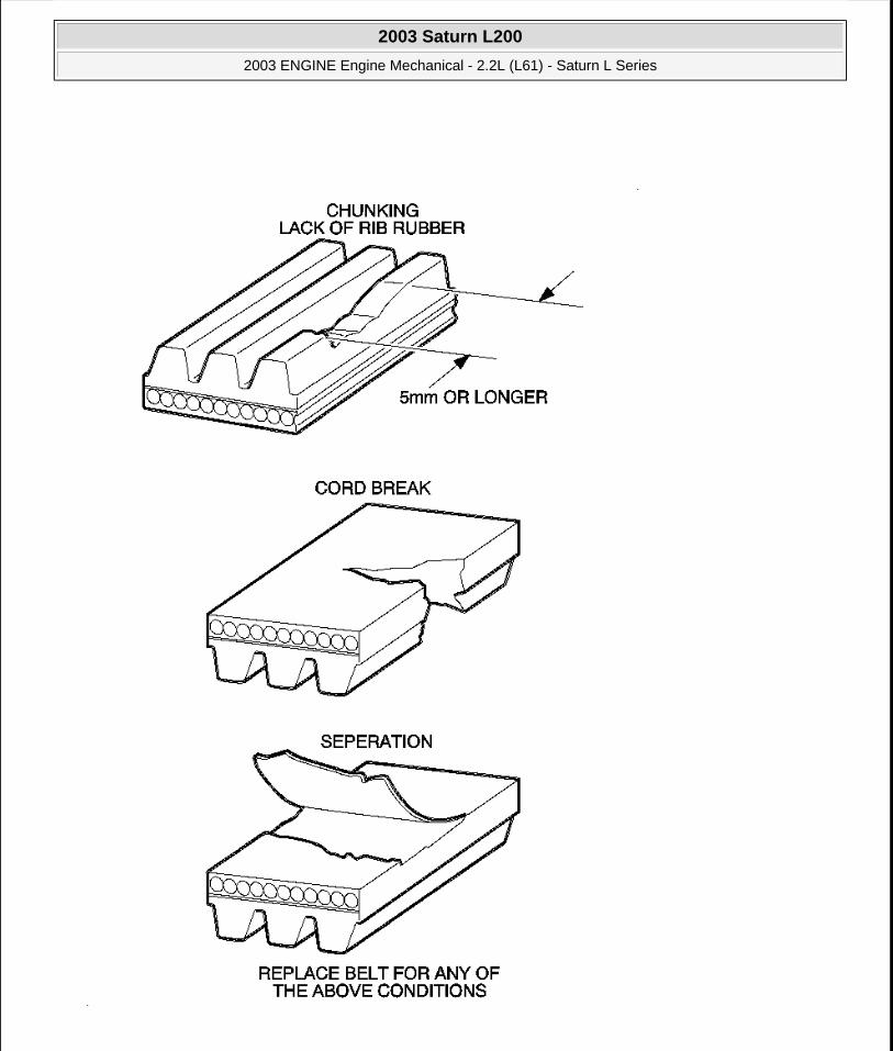
2003 Saturn L200
2003 ENGINE Engine Mechanical - 2.2L (L61) - Saturn L Series
steve
Monday, May 09, 2011 12:52:00 PM Page 60 © 2006 Mitchell Repair Information Company, LLC.

Fig. 25: Chunking, Cord Breakage Or Separation DO Warrant Drive Belt Replacement Courtesy of GENERAL MOTORS CORP.
Belts that have chunking longer than 5 mm (13/16 in) in one or more places should be replaced.
Belts should also be replaced if cord breakage or fabric separation is observed.
DRIVE BELT TENSIONER DIAGNOSIS
Drive Belt Tensioner Diagnosis
REPAIR INSTRUCTIONS
DRIVE BELT REPLACEMENT
Removal Procedure
Step Action Yes No
1Remove the drive belt. Inspect the drive belt tensioner pulley. Is the drive belt tensioner pulley loose or misaligned? Go to Step 4 Go to Step 2
2Rotate the drive belt tensioner. Does the tensioner rotate without any unusual resistance or binding? Go to Step 3 Go to Step 4
3
1. Use a torque wrench in order to measure the torque required to move the tensioner off of the stop.
2. Use a torque wrench on a known good tensioner in order to measure the torque required to move the tensioner off of the stop.
Is the first torque reading within 10 percent of the second torque reading? System OK Go to Step 4
4Replace the drive belt tensioner. Refer to Drive Belt Tensioner Replacement. Is the repair complete? System OK
-
2003 Saturn L200
2003 ENGINE Engine Mechanical - 2.2L (L61) - Saturn L Series
steve
Monday, May 09, 2011 12:52:00 PM Page 61 © 2006 Mitchell Repair Information Company, LLC.
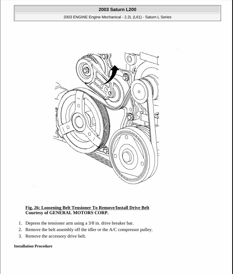
Fig. 26: Loosening Belt Tensioner To Remove/Install Drive Belt Courtesy of GENERAL MOTORS CORP.
1. Depress the tensioner arm using a 3/8 in. drive breaker bar.
2. Remove the belt assembly off the idler or the A/C compressor pulley.
3. Remove the accessory drive belt.
Installation Procedure
2003 Saturn L200
2003 ENGINE Engine Mechanical - 2.2L (L61) - Saturn L Series
steve
Monday, May 09, 2011 12:52:00 PM Page 62 © 2006 Mitchell Repair Information Company, LLC.

Fig. 27: Loosening Belt Tensioner To Remove/Install Drive Belt Courtesy of GENERAL MOTORS CORP.
1. Route the belt around all of the pulleys, except for the idler pulley.
2. Depress the tensioner arm using a 3/8 in. drive breaker bar.
3. Slip the belt over the idler pulley.
DRIVE BELT TENSIONER REPLACEMENT
Removal Procedure
IMPORTANT: Make sure that the belt is properly aligned on the pulleys.
2003 Saturn L200
2003 ENGINE Engine Mechanical - 2.2L (L61) - Saturn L Series
steve
Monday, May 09, 2011 12:52:00 PM Page 63 © 2006 Mitchell Repair Information Company, LLC.

Fig. 28: Loosening Belt Tensioner To Remove/Install Drive Belt Courtesy of GENERAL MOTORS CORP.
1. Remove the accessory drive belt.
CAUTION: The tensioner assembly's internal parts are not serviceable. To avoid injury, do not disassemble the tensioner.
2003 Saturn L200
2003 ENGINE Engine Mechanical - 2.2L (L61) - Saturn L Series
steve
Monday, May 09, 2011 12:52:00 PM Page 64 © 2006 Mitchell Repair Information Company, LLC.

Fig. 29: Removing & Installing Belt Tensioner Bolt Courtesy of GENERAL MOTORS CORP.
2. Remove the belt tensioner bolt.
3. Remove the belt tensioner.
Installation Procedure
2003 Saturn L200
2003 ENGINE Engine Mechanical - 2.2L (L61) - Saturn L Series
steve
Monday, May 09, 2011 12:52:00 PM Page 65 © 2006 Mitchell Repair Information Company, LLC.
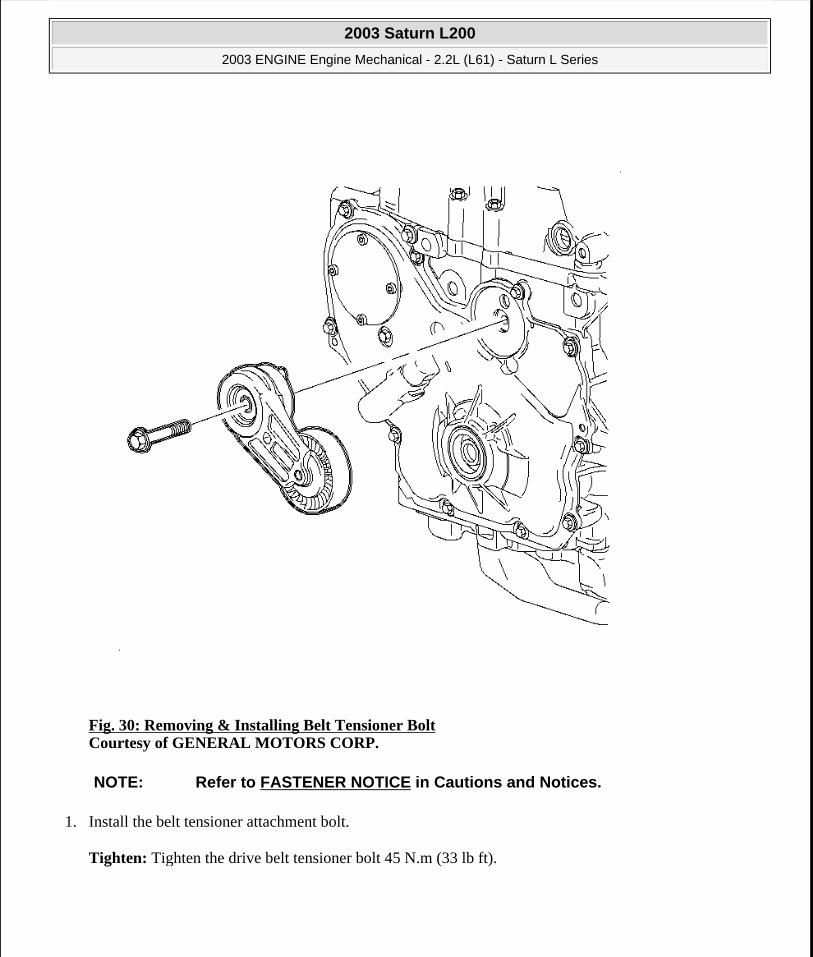
Fig. 30: Removing & Installing Belt Tensioner Bolt Courtesy of GENERAL MOTORS CORP.
1. Install the belt tensioner attachment bolt.
Tighten: Tighten the drive belt tensioner bolt 45 N.m (33 lb ft).
NOTE: Refer to FASTENER NOTICE in Cautions and Notices.
2003 Saturn L200
2003 ENGINE Engine Mechanical - 2.2L (L61) - Saturn L Series
steve
Monday, May 09, 2011 12:52:00 PM Page 66 © 2006 Mitchell Repair Information Company, LLC.

Fig. 31: Loosening Belt Tensioner To Remove/Install Drive Belt Courtesy of GENERAL MOTORS CORP.
2. Install the accessory drive belt.
ENGINE OIL PRESSURE SENSOR AND/OR SWITCH REPLACEMENT
Removal Procedure
2003 Saturn L200
2003 ENGINE Engine Mechanical - 2.2L (L61) - Saturn L Series
steve
Monday, May 09, 2011 12:52:00 PM Page 67 © 2006 Mitchell Repair Information Company, LLC.
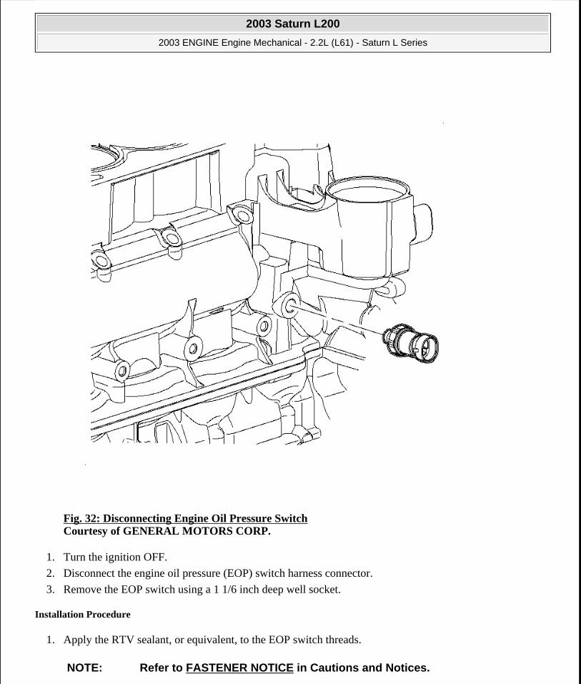
Fig. 32: Disconnecting Engine Oil Pressure Switch Courtesy of GENERAL MOTORS CORP.
1. Turn the ignition OFF.
2. Disconnect the engine oil pressure (EOP) switch harness connector.
3. Remove the EOP switch using a 1 1/6 inch deep well socket.
Installation Procedure
1. Apply the RTV sealant, or equivalent, to the EOP switch threads.
NOTE: Refer to FASTENER NOTICE in Cautions and Notices.
2003 Saturn L200
2003 ENGINE Engine Mechanical - 2.2L (L61) - Saturn L Series
steve
Monday, May 09, 2011 12:52:00 PM Page 68 © 2006 Mitchell Repair Information Company, LLC.

2. Install the EOP switch.
Tighten: Tighten the engine oil pressure switch to 10 N.m (89 lb in).
3. Connect the EOP switch harness connector. Push in the connector until a click is heard, then pull back to confirm a positive engagement.
4. Check the oil level and fill if low.
5. Start the engine and check the engine for leaks.
ENGINE MOUNT INSPECTION
1. Support the engine.
2. Observe the engine mount while raising the engine. Raising the engine removes the weight from the engine mount and creates slight tension on the rubber.
3. Replace the engine mount if the engine mount exhibits any of the following conditions:
The hard rubber is covered with heat check cracks.
The rubber is separated from the metal plate of the engine mount.
The rubber is split through the center of the engine mount.
The engine mount itself is leaking fluid.
4. For engine mount replacement. Refer to Engine Mount Replacement.
POWERTRAIN MOUNT BALANCE PROCEDURE - TOTAL MOUNT (W/AUTOMATIC TRANSAXLE)
1. Raise and support the vehicle. Refer to Lifting and Jacking the Vehicle in General Information.
IMPORTANT: Before replacing any engine mount due to suspected fluid loss, verify that the source of the fluid is the engine mount, not the engine or accessories.
IMPORTANT: Follow the balance procedure in the order listed in the following steps. Powertrain mounts must be tightened in sequence.
2003 Saturn L200
2003 ENGINE Engine Mechanical - 2.2L (L61) - Saturn L Series
steve
Monday, May 09, 2011 12:52:00 PM Page 69 © 2006 Mitchell Repair Information Company, LLC.
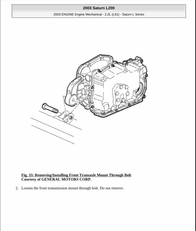
Fig. 33: Removing/Installing Front Transaxle Mount Through Bolt Courtesy of GENERAL MOTORS CORP.
2. Loosen the front transmission mount through bolt. Do not remove.
2003 Saturn L200
2003 ENGINE Engine Mechanical - 2.2L (L61) - Saturn L Series
steve
Monday, May 09, 2011 12:52:00 PM Page 70 © 2006 Mitchell Repair Information Company, LLC.

Fig. 34: Removing & Installing Rear Exhaust Manifold Heat Shield Courtesy of GENERAL MOTORS CORP.
3. Loosen the rear transmission mount through bolt. Do not remove.
4. Position two floor jacks with wood blocks under the engine and transmission to support the powertrain assembly.
2003 Saturn L200
2003 ENGINE Engine Mechanical - 2.2L (L61) - Saturn L Series
steve
Monday, May 09, 2011 12:52:00 PM Page 71 © 2006 Mitchell Repair Information Company, LLC.

Fig. 35: Locating Transmission Mount-To-Transmission Bolts Courtesy of GENERAL MOTORS CORP.
5. From the engine compartment, loosen the transmission mount to transmission bolts.
2003 Saturn L200
2003 ENGINE Engine Mechanical - 2.2L (L61) - Saturn L Series
steve
Monday, May 09, 2011 12:52:00 PM Page 72 © 2006 Mitchell Repair Information Company, LLC.

Fig. 36: Locating Engine Mount-To-Intermediate Bracket Bolts Courtesy of GENERAL MOTORS CORP.
6. Loosen the engine mount to intermediate bracket bolts.
7. Reposition the floor jacks to allow a 1/8 inch gap between the mount and mount bracket.
2003 Saturn L200
2003 ENGINE Engine Mechanical - 2.2L (L61) - Saturn L Series
steve
Monday, May 09, 2011 12:52:00 PM Page 73 © 2006 Mitchell Repair Information Company, LLC.
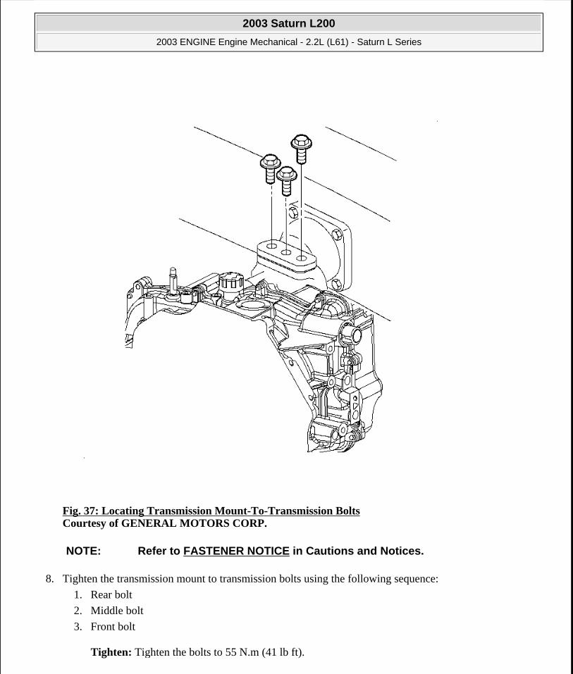
Fig. 37: Locating Transmission Mount-To-Transmission Bolts Courtesy of GENERAL MOTORS CORP.
8. Tighten the transmission mount to transmission bolts using the following sequence:
1. Rear bolt
2. Middle bolt
3. Front bolt
Tighten: Tighten the bolts to 55 N.m (41 lb ft).
NOTE: Refer to FASTENER NOTICE in Cautions and Notices.
2003 Saturn L200
2003 ENGINE Engine Mechanical - 2.2L (L61) - Saturn L Series
steve
Monday, May 09, 2011 12:52:00 PM Page 74 © 2006 Mitchell Repair Information Company, LLC.

Fig. 38: Locating Engine Mount-To-Intermediate Bracket Bolts Courtesy of GENERAL MOTORS CORP.
9. Tighten the engine mount to intermediate bracket bolts starting with the center bolt.
Tighten: Tighten the bolts to 55 N.m (41 lb ft).
10. Remove the floor jacks.
11. Shake the powertrain vigorously from front to rear and allow the powertrain to settle.
2003 Saturn L200
2003 ENGINE Engine Mechanical - 2.2L (L61) - Saturn L Series
steve
Monday, May 09, 2011 12:52:00 PM Page 75 © 2006 Mitchell Repair Information Company, LLC.

Fig. 39: Locating Rear Transmission Mount Through-Bolt - Automatic Transaxle Courtesy of GENERAL MOTORS CORP.
12. Tighten the rear transmission mount through bolt.
Tighten: Tighten the bolts to 90 N.m (66 lb ft).
2003 Saturn L200
2003 ENGINE Engine Mechanical - 2.2L (L61) - Saturn L Series
steve
Monday, May 09, 2011 12:52:00 PM Page 76 © 2006 Mitchell Repair Information Company, LLC.

Fig. 40: Removing/Installing Front Transaxle Mount Through Bolt Courtesy of GENERAL MOTORS CORP.
13. Tighten the front transmission mount through bolt.
Tighten: Tighten the bolts to 60 N.m (44 lb ft).
14. Lower the vehicle.
POWERTRAIN MOUNT BALANCE PROCEDURE - TOTAL MOUNT (W/MANUAL TRANSAXLE)
IMPORTANT: Follow the balance procedure in the order listed in the following steps. Powertrain mounts must be tightened in sequence.
2003 Saturn L200
2003 ENGINE Engine Mechanical - 2.2L (L61) - Saturn L Series
steve
Monday, May 09, 2011 12:52:00 PM Page 77 © 2006 Mitchell Repair Information Company, LLC.

1. Raise and support the vehicle. Refer to Lifting and Jacking the Vehicle in General Information.
Fig. 41: Locating Front Transmission Mount Through-Bolt - Manual Transaxle Courtesy of GENERAL MOTORS CORP.
2. Loosen the front transmission mount through bolt. Do not remove.
2003 Saturn L200
2003 ENGINE Engine Mechanical - 2.2L (L61) - Saturn L Series
steve
Monday, May 09, 2011 12:52:00 PM Page 78 © 2006 Mitchell Repair Information Company, LLC.

Fig. 42: Locating Rear Transmission Mount Through-Bolt - Manual Transaxle Courtesy of GENERAL MOTORS CORP.
3. Loosen the rear transmission mount through bolt. Do not remove.
4. Position two floor jacks with wood blocks under the engine and transmission to support the powertrain assembly.
2003 Saturn L200
2003 ENGINE Engine Mechanical - 2.2L (L61) - Saturn L Series
steve
Monday, May 09, 2011 12:52:00 PM Page 79 © 2006 Mitchell Repair Information Company, LLC.

Fig. 43: Locating Transmission Mount-To-Transmission Bolts Courtesy of GENERAL MOTORS CORP.
5. From the engine compartment, loosen the transmission mount to transmission bolts.
2003 Saturn L200
2003 ENGINE Engine Mechanical - 2.2L (L61) - Saturn L Series
steve
Monday, May 09, 2011 12:52:00 PM Page 80 © 2006 Mitchell Repair Information Company, LLC.
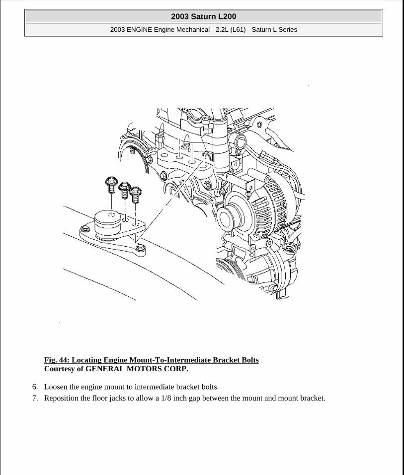
Fig. 44: Locating Engine Mount-To-Intermediate Bracket Bolts Courtesy of GENERAL MOTORS CORP.
6. Loosen the engine mount to intermediate bracket bolts.
7. Reposition the floor jacks to allow a 1/8 inch gap between the mount and mount bracket.
2003 Saturn L200
2003 ENGINE Engine Mechanical - 2.2L (L61) - Saturn L Series
steve
Monday, May 09, 2011 12:52:00 PM Page 81 © 2006 Mitchell Repair Information Company, LLC.

Fig. 45: Locating Transmission Mount-To-Transmission Bolts Courtesy of GENERAL MOTORS CORP.
8. Tighten the transmission mount to transmission bolts using the following sequence:
1. Rear bolt
2. Middle bolt
3. Front bolt
Tighten: Tighten the bolts to 55 N.m (41 lb ft).
NOTE: Refer to FASTENER NOTICE in Cautions and Notices.
2003 Saturn L200
2003 ENGINE Engine Mechanical - 2.2L (L61) - Saturn L Series
steve
Monday, May 09, 2011 12:52:00 PM Page 82 © 2006 Mitchell Repair Information Company, LLC.

Fig. 46: Locating Engine Mount-To-Intermediate Bracket Bolts Courtesy of GENERAL MOTORS CORP.
9. Tighten the engine mount to intermediate bracket bolts starting with the center bolt.
Tighten: Tighten the bolts to 55 N.m (41 lb ft).
10. Remove the floor jacks.
11. Shake the powertrain vigorously from front to rear and allow the powertrain to settle.
2003 Saturn L200
2003 ENGINE Engine Mechanical - 2.2L (L61) - Saturn L Series
steve
Monday, May 09, 2011 12:52:00 PM Page 83 © 2006 Mitchell Repair Information Company, LLC.

Fig. 47: Locating Rear Transmission Mount Through-Bolt - Manual Transaxle Courtesy of GENERAL MOTORS CORP.
12. Tighten the rear transmission mount through bolt.
Tighten: Tighten the bolts to 60 N.m (44 lb ft).
2003 Saturn L200
2003 ENGINE Engine Mechanical - 2.2L (L61) - Saturn L Series
steve
Monday, May 09, 2011 12:52:00 PM Page 84 © 2006 Mitchell Repair Information Company, LLC.
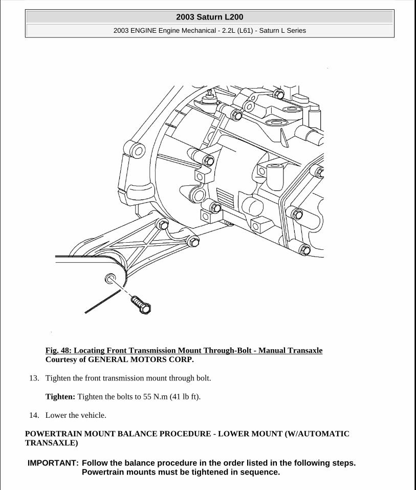
Fig. 48: Locating Front Transmission Mount Through-Bolt - Manual Transaxle Courtesy of GENERAL MOTORS CORP.
13. Tighten the front transmission mount through bolt.
Tighten: Tighten the bolts to 55 N.m (41 lb ft).
14. Lower the vehicle.
POWERTRAIN MOUNT BALANCE PROCEDURE - LOWER MOUNT (W/AUTOMATIC TRANSAXLE)
IMPORTANT: Follow the balance procedure in the order listed in the following steps. Powertrain mounts must be tightened in sequence.
2003 Saturn L200
2003 ENGINE Engine Mechanical - 2.2L (L61) - Saturn L Series
steve
Monday, May 09, 2011 12:52:01 PM Page 85 © 2006 Mitchell Repair Information Company, LLC.
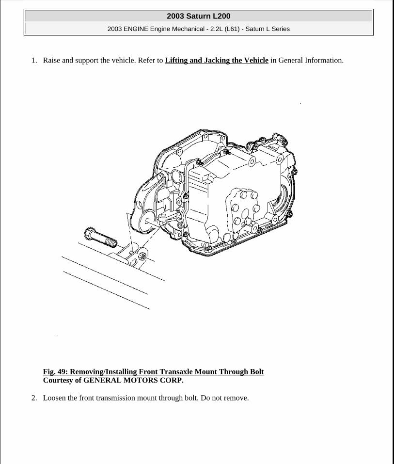
1. Raise and support the vehicle. Refer to Lifting and Jacking the Vehicle in General Information.
Fig. 49: Removing/Installing Front Transaxle Mount Through Bolt Courtesy of GENERAL MOTORS CORP.
2. Loosen the front transmission mount through bolt. Do not remove.
2003 Saturn L200
2003 ENGINE Engine Mechanical - 2.2L (L61) - Saturn L Series
steve
Monday, May 09, 2011 12:52:01 PM Page 86 © 2006 Mitchell Repair Information Company, LLC.

Fig. 50: Locating Rear Transmission Mount Through-Bolt - Automatic Transaxle Courtesy of GENERAL MOTORS CORP.
3. Loosen the rear transmission mount through bolt. Do not remove.
4. Shake the powertrain vigorously from front to rear and allow powertrain to settle.
5. Tighten the rear transmission mount through bolt.
Tighten: Tighten the bolt to 90 N.m (66 lb ft).
NOTE: Refer to FASTENER NOTICE in Cautions and Notices.
2003 Saturn L200
2003 ENGINE Engine Mechanical - 2.2L (L61) - Saturn L Series
steve
Monday, May 09, 2011 12:52:01 PM Page 87 © 2006 Mitchell Repair Information Company, LLC.

Fig. 51: Removing/Installing Front Transaxle Mount Through Bolt Courtesy of GENERAL MOTORS CORP.
6. Tighten the front transmission mount through bolt.
Tighten: Tighten the bolt to 60 N.m (44 lb ft).
7. Lower the vehicle.
POWERTRAIN MOUNT BALANCE PROCEDURE - LOWER MOUNT (W/MANUAL TRANSAXLE)
IMPORTANT: Follow the balance procedure in the order listed in the following steps. Powertrain mounts must be tightened in sequence.
2003 Saturn L200
2003 ENGINE Engine Mechanical - 2.2L (L61) - Saturn L Series
steve
Monday, May 09, 2011 12:52:01 PM Page 88 © 2006 Mitchell Repair Information Company, LLC.

1. Raise and support the vehicle. Refer to Lifting and Jacking the Vehicle in General Information.
Fig. 52: Locating Front Transmission Mount Through-Bolt - Manual Transaxle Courtesy of GENERAL MOTORS CORP.
2. Loosen the front transmission mount through bolt. Do not remove.
2003 Saturn L200
2003 ENGINE Engine Mechanical - 2.2L (L61) - Saturn L Series
steve
Monday, May 09, 2011 12:52:01 PM Page 89 © 2006 Mitchell Repair Information Company, LLC.
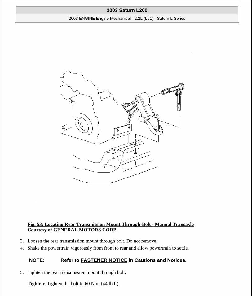
Fig. 53: Locating Rear Transmission Mount Through-Bolt - Manual Transaxle Courtesy of GENERAL MOTORS CORP.
3. Loosen the rear transmission mount through bolt. Do not remove.
4. Shake the powertrain vigorously from front to rear and allow powertrain to settle.
5. Tighten the rear transmission mount through bolt.
Tighten: Tighten the bolt to 60 N.m (44 lb ft).
NOTE: Refer to FASTENER NOTICE in Cautions and Notices.
2003 Saturn L200
2003 ENGINE Engine Mechanical - 2.2L (L61) - Saturn L Series
steve
Monday, May 09, 2011 12:52:01 PM Page 90 © 2006 Mitchell Repair Information Company, LLC.

Fig. 54: Locating Front Transmission Mount Through-Bolt - Manual Transaxle Courtesy of GENERAL MOTORS CORP.
6. Tighten the front transmission mount through bolt.
Tighten: Tighten the bolt to 55 N.m (41 lb ft).
7. Lower the vehicle.
ENGINE MOUNT BRACKET REPLACEMENT
Removal Procedure
2003 Saturn L200
2003 ENGINE Engine Mechanical - 2.2L (L61) - Saturn L Series
steve
Monday, May 09, 2011 12:52:01 PM Page 91 © 2006 Mitchell Repair Information Company, LLC.
Fig. 55: Exploded View Of Engine Mount Assembly Courtesy of GENERAL MOTORS CORP.
1. Remove the engine mount. Refer to Engine Mount Replacement.
2003 Saturn L200
2003 ENGINE Engine Mechanical - 2.2L (L61) - Saturn L Series
steve
Monday, May 09, 2011 12:52:01 PM Page 92 © 2006 Mitchell Repair Information Company, LLC.
Fig. 56: Removing & Installing Engine Mount Bracket Courtesy of GENERAL MOTORS CORP.
2. Remove the engine mount bracket to engine bolts.
3. Remove the engine mount bracket from the engine.
Installation Procedure
NOTE: Refer to FASTENER NOTICE in Cautions and Notices.
2003 Saturn L200
2003 ENGINE Engine Mechanical - 2.2L (L61) - Saturn L Series
steve
Monday, May 09, 2011 12:52:01 PM Page 93 © 2006 Mitchell Repair Information Company, LLC.

Fig. 57: Removing & Installing Engine Mount Bracket Courtesy of GENERAL MOTORS CORP.
1. Install the engine mount bracket to the engine.
Tighten: Tighten the engine mount bracket to engine bolts to 90 N.m (66 lb ft).
2003 Saturn L200
2003 ENGINE Engine Mechanical - 2.2L (L61) - Saturn L Series
steve
Monday, May 09, 2011 12:52:01 PM Page 94 © 2006 Mitchell Repair Information Company, LLC.
Fig. 58: Exploded View Of Engine Mount Assembly Courtesy of GENERAL MOTORS CORP.
2. Install the engine mount. Refer to Engine Mount Replacement.
ENGINE MOUNT REPLACEMENT
Removal Procedure
2003 Saturn L200
2003 ENGINE Engine Mechanical - 2.2L (L61) - Saturn L Series
steve
Monday, May 09, 2011 12:52:01 PM Page 95 © 2006 Mitchell Repair Information Company, LLC.

Fig. 59: Removing & Installing Air Cleaner Assembly Courtesy of GENERAL MOTORS CORP.
1. Remove the air cleaner assembly.
2003 Saturn L200
2003 ENGINE Engine Mechanical - 2.2L (L61) - Saturn L Series
steve
Monday, May 09, 2011 12:52:01 PM Page 96 © 2006 Mitchell Repair Information Company, LLC.

Fig. 60: Identifying Properly Installed Engine Support Fixture Courtesy of GENERAL MOTORS CORP.
2. Support the engine.
2003 Saturn L200
2003 ENGINE Engine Mechanical - 2.2L (L61) - Saturn L Series
steve
Monday, May 09, 2011 12:52:01 PM Page 97 © 2006 Mitchell Repair Information Company, LLC.

Fig. 61: Locating Engine Mount-To-Intermediate Bracket Bolts Courtesy of GENERAL MOTORS CORP.
3. Remove the engine mount to bracket bolts.
2003 Saturn L200
2003 ENGINE Engine Mechanical - 2.2L (L61) - Saturn L Series
steve
Monday, May 09, 2011 12:52:01 PM Page 98 © 2006 Mitchell Repair Information Company, LLC.

Fig. 62: Removing & Installing Engine Mount Assembly Courtesy of GENERAL MOTORS CORP.
4. Remove the engine mount to body bolts.
5. Remove the engine mount from the vehicle.
2003 Saturn L200
2003 ENGINE Engine Mechanical - 2.2L (L61) - Saturn L Series
steve
Monday, May 09, 2011 12:52:01 PM Page 99 © 2006 Mitchell Repair Information Company, LLC.

Fig. 63: Exploded View Of Engine Mount Assembly Courtesy of GENERAL MOTORS CORP.
6. Remove the bolt the retains the mount to the engine mount body bracket.
7. Remove the mount from the mount bracket and isolation pad.
Installation Procedure
IMPORTANT: Retain the isolation pad for assembly.
2003 Saturn L200
2003 ENGINE Engine Mechanical - 2.2L (L61) - Saturn L Series
steve
Monday, May 09, 2011 12:52:01 PM Page 100 © 2006 Mitchell Repair Information Company, LLC.

Fig. 64: Exploded View Of Engine Mount Assembly Courtesy of GENERAL MOTORS CORP.
1. Assemble the engine mount, engine mount bracket and isolation pad.
Tighten: Tighten the engine mount to bracket bolt to 90 N.m (66 lb ft).
NOTE: Refer to FASTENER NOTICE in Cautions and Notices.
IMPORTANT: The isolation must be attached to the engine mount. Replace the isolation pad if necessary.
2003 Saturn L200
2003 ENGINE Engine Mechanical - 2.2L (L61) - Saturn L Series
steve
Monday, May 09, 2011 12:52:01 PM Page 101 © 2006 Mitchell Repair Information Company, LLC.

Fig. 65: Removing & Installing Engine Mount Assembly Courtesy of GENERAL MOTORS CORP.
2. Install the engine mount to the vehicle. Hand tighten the bolts at this time.
2003 Saturn L200
2003 ENGINE Engine Mechanical - 2.2L (L61) - Saturn L Series
steve
Monday, May 09, 2011 12:52:01 PM Page 102 © 2006 Mitchell Repair Information Company, LLC.
Fig. 66: Locating Engine Mount-To-Intermediate Bracket Bolts Courtesy of GENERAL MOTORS CORP.
3. Install the engine mount to engine bracket bolts.
Tighten:
Tighten the engine mount to bracket bolts to 55 N.m (41 lb ft).
Tighten the engine mount to vehicle bolts to 55 N.m (41 lb ft).
4. Remove the engine support fixture.
5. Balance the engine mounts. Refer to Powertrain Mount Balance Procedure - Total Mount (W/Automatic Transaxle) or Powertrain Mount Balance Procedure - Total Mount (W/Manual
2003 Saturn L200
2003 ENGINE Engine Mechanical - 2.2L (L61) - Saturn L Series
steve
Monday, May 09, 2011 12:52:01 PM Page 103 © 2006 Mitchell Repair Information Company, LLC.
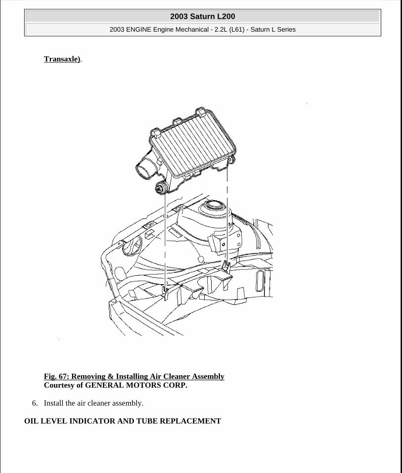
Transaxle).
Fig. 67: Removing & Installing Air Cleaner Assembly Courtesy of GENERAL MOTORS CORP.
6. Install the air cleaner assembly.
OIL LEVEL INDICATOR AND TUBE REPLACEMENT
2003 Saturn L200
2003 ENGINE Engine Mechanical - 2.2L (L61) - Saturn L Series
steve
Monday, May 09, 2011 12:52:01 PM Page 104 © 2006 Mitchell Repair Information Company, LLC.

Fig. 68: Removing & Installing Oil Level Indicator & Tube Courtesy of GENERAL MOTORS CORP.
1. Remove the tube bracket to intake manifold bolt.
2. Remove the tube from the engine block.
CRANKCASE VENTILATION HOSES/PIPES REPLACEMENT
Removal Procedure
2003 Saturn L200
2003 ENGINE Engine Mechanical - 2.2L (L61) - Saturn L Series
steve
Monday, May 09, 2011 12:52:01 PM Page 105 © 2006 Mitchell Repair Information Company, LLC.

Fig. 69: Connecting Crankcase Ventilation Hose To Camshaft Cover Courtesy of GENERAL MOTORS CORP.
1. Disconnect the crankcase ventilation hose from the camshaft cover.
2. Disconnect the crankcase ventilation hose from the intake manifold.
Installation Procedure
2003 Saturn L200
2003 ENGINE Engine Mechanical - 2.2L (L61) - Saturn L Series
steve
Monday, May 09, 2011 12:52:01 PM Page 106 © 2006 Mitchell Repair Information Company, LLC.

Fig. 70: Connecting Crankcase Ventilation Hose To Camshaft Cover Courtesy of GENERAL MOTORS CORP.
1. Connect the crankcase ventilation hose to the camshaft cover.
2. Connect the crankcase ventilation hose to the intake manifold.
INTAKE MANIFOLD REPLACEMENT
Removal Procedure
1. Remove the air cleaner outlet resonator.
2. Remove the throttle body. Refer to THROTTLE BODY in Removal and Installation in Engine Performance.
3. Disconnect the PCV hose.
4. Disconnect the purge solenoid tube.
2003 Saturn L200
2003 ENGINE Engine Mechanical - 2.2L (L61) - Saturn L Series
steve
Monday, May 09, 2011 12:52:01 PM Page 107 © 2006 Mitchell Repair Information Company, LLC.

5. Disconnect the brake booster hose.
6. Remove the oil level indicator tube bolt.
7. Remove the fuel rail. Refer to FUEL RAIL & INJECTORS in Removal and Installation in Engine Performance.
8. Disconnect the knock sensor electrical connector.
Fig. 71: View Of Knock Sensor Connector Courtesy of GENERAL MOTORS CORP.
9. Remove the knock sensor harness connector from the intake manifold.
2003 Saturn L200
2003 ENGINE Engine Mechanical - 2.2L (L61) - Saturn L Series
steve
Monday, May 09, 2011 12:52:01 PM Page 108 © 2006 Mitchell Repair Information Company, LLC.
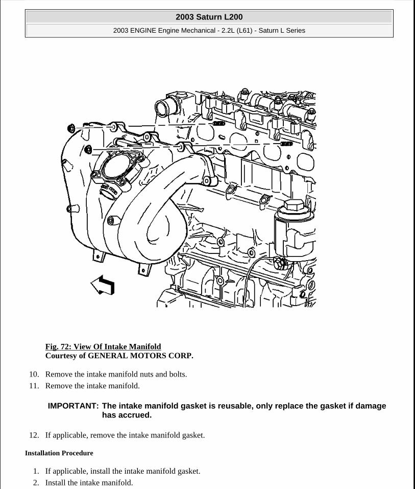
Fig. 72: View Of Intake Manifold Courtesy of GENERAL MOTORS CORP.
10. Remove the intake manifold nuts and bolts.
11. Remove the intake manifold.
12. If applicable, remove the intake manifold gasket.
Installation Procedure
1. If applicable, install the intake manifold gasket.
2. Install the intake manifold.
IMPORTANT: The intake manifold gasket is reusable, only replace the gasket if damage has accrued.
2003 Saturn L200
2003 ENGINE Engine Mechanical - 2.2L (L61) - Saturn L Series
steve
Monday, May 09, 2011 12:52:01 PM Page 109 © 2006 Mitchell Repair Information Company, LLC.
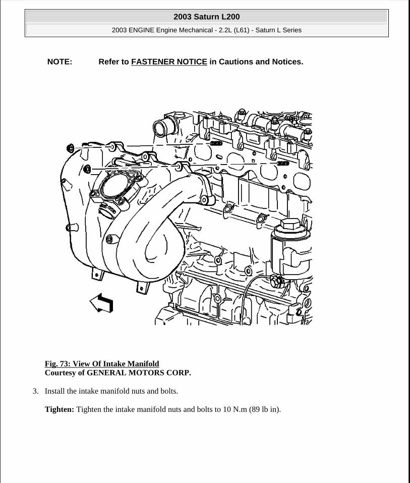
Fig. 73: View Of Intake Manifold Courtesy of GENERAL MOTORS CORP.
3. Install the intake manifold nuts and bolts.
Tighten: Tighten the intake manifold nuts and bolts to 10 N.m (89 lb in).
NOTE: Refer to FASTENER NOTICE in Cautions and Notices.
2003 Saturn L200
2003 ENGINE Engine Mechanical - 2.2L (L61) - Saturn L Series
steve
Monday, May 09, 2011 12:52:01 PM Page 110 © 2006 Mitchell Repair Information Company, LLC.

Fig. 74: View Of Knock Sensor Connector Courtesy of GENERAL MOTORS CORP.
4. Install the knock sensor harness connector to the intake manifold.
5. Connect the knock sensor electrical connector.
6. Install the fuel rail. Refer to FUEL RAIL & INJECTORS in Removal and Installation in Engine Performance.
7. Install the throttle body.
8. Install the oil level indicator tube bolt.
Tighten: Tighten the oil level indicator tube bolt to 10 N.m (89 lb in).
2003 Saturn L200
2003 ENGINE Engine Mechanical - 2.2L (L61) - Saturn L Series
steve
Monday, May 09, 2011 12:52:01 PM Page 111 © 2006 Mitchell Repair Information Company, LLC.

9. Connect the brake booster hose.
10. Connect the purge solenoid tube.
11. Connect the PCV hose.
12. Install the throttle body. Refer to THROTTLE BODY in Removal and Installation in Engine Performance.
13. Install the air cleaner outlet resonator.
CRANKSHAFT BALANCER REPLACEMENT
Tools Required
J 38122-A Harmonic Balancer Holder
Removal Procedure
2003 Saturn L200
2003 ENGINE Engine Mechanical - 2.2L (L61) - Saturn L Series
steve
Monday, May 09, 2011 12:52:01 PM Page 112 © 2006 Mitchell Repair Information Company, LLC.

Fig. 75: Removing & Installing Harmonic Balancer Using Holder On Damper Assembly Courtesy of GENERAL MOTORS CORP.
1. Install the J 38122-A onto the damper assembly.
2. Remove and discard the damper retaining bolt and washer. Use the J 38122-A and breaker bar in order to prevent the crankshaft from rotating when loosening the bolt.
2003 Saturn L200
2003 ENGINE Engine Mechanical - 2.2L (L61) - Saturn L Series
steve
Monday, May 09, 2011 12:52:01 PM Page 113 © 2006 Mitchell Repair Information Company, LLC.
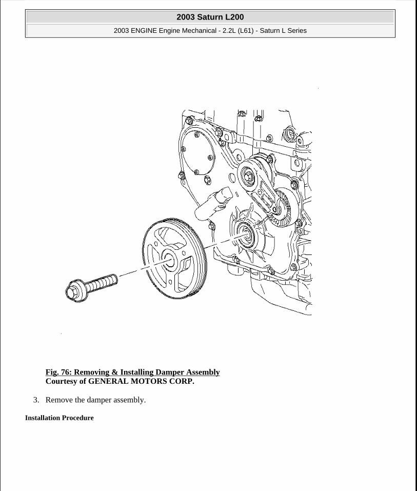
Fig. 76: Removing & Installing Damper Assembly Courtesy of GENERAL MOTORS CORP.
3. Remove the damper assembly.
Installation Procedure
2003 Saturn L200
2003 ENGINE Engine Mechanical - 2.2L (L61) - Saturn L Series
steve
Monday, May 09, 2011 12:52:01 PM Page 114 © 2006 Mitchell Repair Information Company, LLC.

Fig. 77: Removing & Installing Damper Assembly Courtesy of GENERAL MOTORS CORP.
1. Lubricate the front oil seal and seal surface of the crankshaft balancer with an engine oil supplement.
2. Install the damper onto the crankshaft indexing keyway. Use care to properly align the keyway and flats on the damper with the oil pump drive.
NOTE: Misalignment of the keyway may cause damage to the oil pump.
2003 Saturn L200
2003 ENGINE Engine Mechanical - 2.2L (L61) - Saturn L Series
steve
Monday, May 09, 2011 12:52:01 PM Page 115 © 2006 Mitchell Repair Information Company, LLC.

Fig. 78: Removing & Installing Harmonic Balancer Using Holder On Damper Assembly Courtesy of GENERAL MOTORS CORP.
3. Install the new retaining bolt and washer using the J 38122-A and a breaker bar to hold the crankshaft.
Tighten: Tighten the crankshaft pulley bolt to 100 N.m (74 lb ft) plus 75 degrees.
ENGINE FRONT COVER REPLACEMENT (WITH OIL PUMP ASSEMBLY)
Tools Required
NOTE: Refer to FASTENER NOTICE in Cautions and Notices.
2003 Saturn L200
2003 ENGINE Engine Mechanical - 2.2L (L61) - Saturn L Series
steve
Monday, May 09, 2011 12:52:01 PM Page 116 © 2006 Mitchell Repair Information Company, LLC.

J 38122-A Crankshaft Pulley Holder
SA9105E Engine Support Fixture (3-Bar). See Special Tools and Equipment.
J 43405 Engine Support Fixture Adapter
Removal Procedure
Fig. 79: Removing & Installing Air Cleaner Assembly Courtesy of GENERAL MOTORS CORP.
1. Disconnect the negative battery cable.
2. Remove the air cleaner assembly.
2003 Saturn L200
2003 ENGINE Engine Mechanical - 2.2L (L61) - Saturn L Series
steve
Monday, May 09, 2011 12:52:01 PM Page 117 © 2006 Mitchell Repair Information Company, LLC.
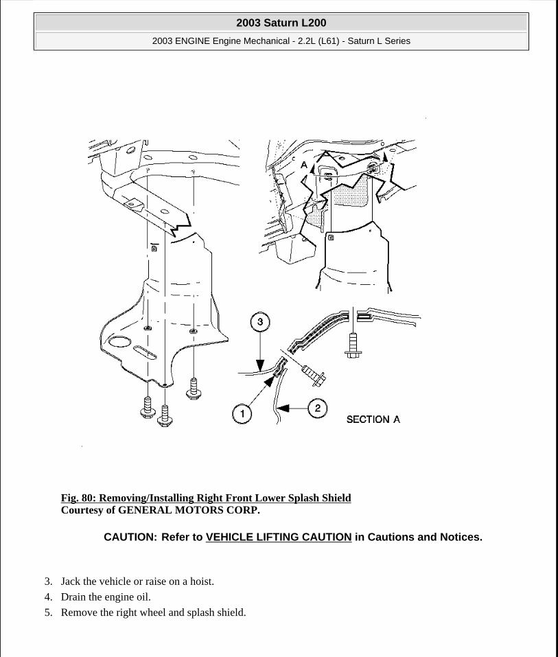
Fig. 80: Removing/Installing Right Front Lower Splash Shield Courtesy of GENERAL MOTORS CORP.
3. Jack the vehicle or raise on a hoist.
4. Drain the engine oil.
5. Remove the right wheel and splash shield.
CAUTION: Refer to VEHICLE LIFTING CAUTION in Cautions and Notices.
2003 Saturn L200
2003 ENGINE Engine Mechanical - 2.2L (L61) - Saturn L Series
steve
Monday, May 09, 2011 12:52:01 PM Page 118 © 2006 Mitchell Repair Information Company, LLC.

Fig. 81: Loosening Belt Tensioner To Remove/Install Drive Belt Courtesy of GENERAL MOTORS CORP.
6. Remove the engine accessory drive belt.
2003 Saturn L200
2003 ENGINE Engine Mechanical - 2.2L (L61) - Saturn L Series
steve
Monday, May 09, 2011 12:52:01 PM Page 119 © 2006 Mitchell Repair Information Company, LLC.

Fig. 82: Removing & Installing Harmonic Balancer Using Holder On Damper Assembly Courtesy of GENERAL MOTORS CORP.
7. Install the J 38122-A .
2003 Saturn L200
2003 ENGINE Engine Mechanical - 2.2L (L61) - Saturn L Series
steve
Monday, May 09, 2011 12:52:01 PM Page 120 © 2006 Mitchell Repair Information Company, LLC.

Fig. 83: Removing & Installing Damper Assembly Courtesy of GENERAL MOTORS CORP.
8. Remove the crankshaft damper pulley and discard the bolt.
IMPORTANT: The crankshaft damper pulley bolt head and washer assembly prevents oil leakage at the center of the pulley. Do not damage the sealing surfaces. If the pulley cannot be removed by pulling with your hand, use a three jaw puller.
IMPORTANT: Do not pry against the cover.
2003 Saturn L200
2003 ENGINE Engine Mechanical - 2.2L (L61) - Saturn L Series
steve
Monday, May 09, 2011 12:52:01 PM Page 121 © 2006 Mitchell Repair Information Company, LLC.

Fig. 84: Removing & Installing Belt Tensioner Bolt Courtesy of GENERAL MOTORS CORP.
9. Remove the belt tensioner.
2003 Saturn L200
2003 ENGINE Engine Mechanical - 2.2L (L61) - Saturn L Series
steve
Monday, May 09, 2011 12:52:01 PM Page 122 © 2006 Mitchell Repair Information Company, LLC.

Fig. 85: Identifying Properly Installed Engine Support Fixture Courtesy of GENERAL MOTORS CORP.
10. Install the SA9105E and the J43405 respectively. See Special Tools and Equipment.
2003 Saturn L200
2003 ENGINE Engine Mechanical - 2.2L (L61) - Saturn L Series
steve
Monday, May 09, 2011 12:52:01 PM Page 123 © 2006 Mitchell Repair Information Company, LLC.

Fig. 86: Removing & Installing Engine Mount Bracket Courtesy of GENERAL MOTORS CORP.
11. Remove the right engine mount. Refer to Engine Mount and Bracket Replacement - Right.
2003 Saturn L200
2003 ENGINE Engine Mechanical - 2.2L (L61) - Saturn L Series
steve
Monday, May 09, 2011 12:52:01 PM Page 124 © 2006 Mitchell Repair Information Company, LLC.

Fig. 87: Removing Front Cover Assembly and Gasket Courtesy of GENERAL MOTORS CORP.
12. Remove the front cover assembly and gasket.
Installation Procedure
2003 Saturn L200
2003 ENGINE Engine Mechanical - 2.2L (L61) - Saturn L Series
steve
Monday, May 09, 2011 12:52:01 PM Page 125 © 2006 Mitchell Repair Information Company, LLC.

Fig. 88: Installing Engine Front Cover Courtesy of GENERAL MOTORS CORP.
1. Install the new front cover gasket and cover the assembly.
2. Install the front cover bolts.
Tighten: Tighten the front cover-to-block bolts to 25 N.m (18 lb ft).
NOTE: Refer to FASTENER NOTICE in Cautions and Notices.
2003 Saturn L200
2003 ENGINE Engine Mechanical - 2.2L (L61) - Saturn L Series
steve
Monday, May 09, 2011 12:52:01 PM Page 126 © 2006 Mitchell Repair Information Company, LLC.

Fig. 89: Removing & Installing Engine Mount Bracket Courtesy of GENERAL MOTORS CORP.
3. Install the right side engine mount. Refer to Engine Mount and Bracket Replacement - Right.
2003 Saturn L200
2003 ENGINE Engine Mechanical - 2.2L (L61) - Saturn L Series
steve
Monday, May 09, 2011 12:52:01 PM Page 127 © 2006 Mitchell Repair Information Company, LLC.
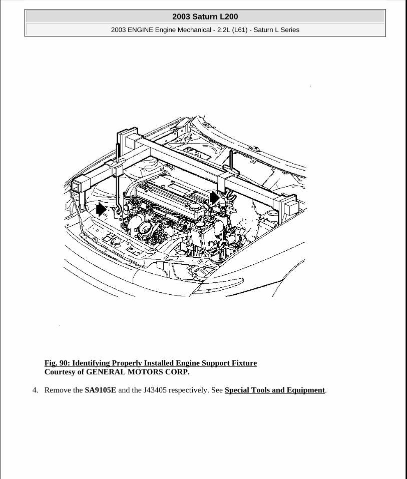
Fig. 90: Identifying Properly Installed Engine Support Fixture Courtesy of GENERAL MOTORS CORP.
4. Remove the SA9105E and the J43405 respectively. See Special Tools and Equipment.
2003 Saturn L200
2003 ENGINE Engine Mechanical - 2.2L (L61) - Saturn L Series
steve
Monday, May 09, 2011 12:52:01 PM Page 128 © 2006 Mitchell Repair Information Company, LLC.
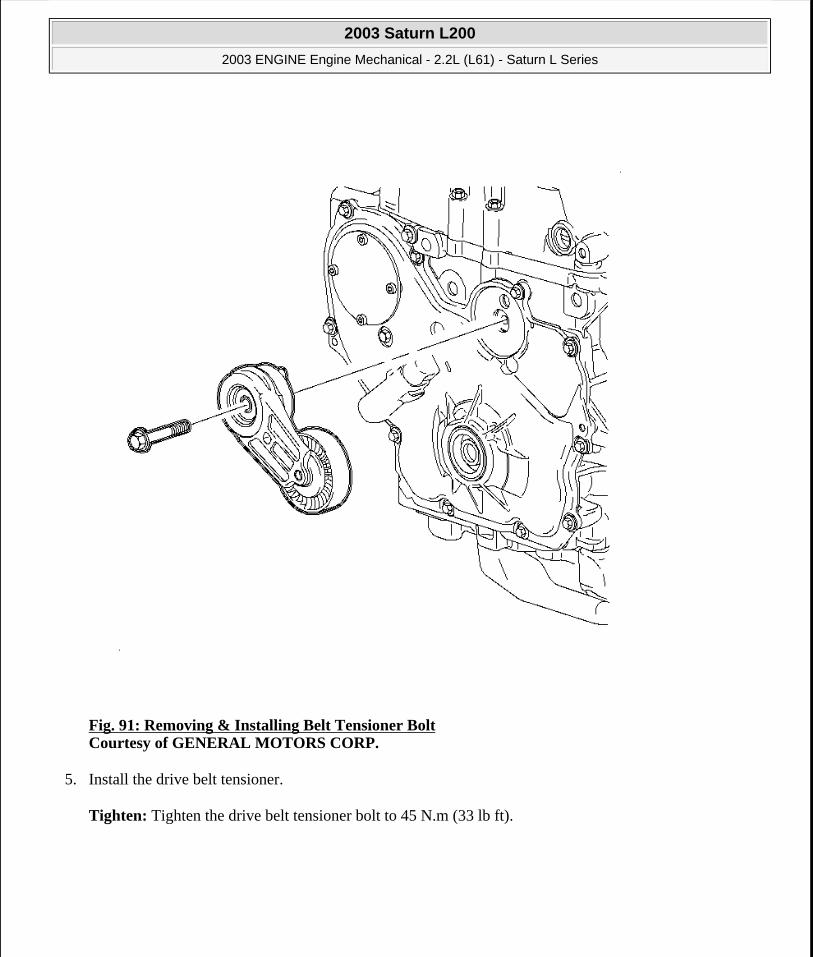
Fig. 91: Removing & Installing Belt Tensioner Bolt Courtesy of GENERAL MOTORS CORP.
5. Install the drive belt tensioner.
Tighten: Tighten the drive belt tensioner bolt to 45 N.m (33 lb ft).
2003 Saturn L200
2003 ENGINE Engine Mechanical - 2.2L (L61) - Saturn L Series
steve
Monday, May 09, 2011 12:52:01 PM Page 129 © 2006 Mitchell Repair Information Company, LLC.

Fig. 92: Removing & Installing Harmonic Balancer Using Holder On Damper Assembly Courtesy of GENERAL MOTORS CORP.
6. Install the crankshaft damper pulley.
1. Lubricate the front seal and sealing surface of the damper pulley with clean motor oil.
2. Install the damper onto the crankshaft indexing keyway. Use care to properly align the flats on the damper with the flats on the oil pump drive.
2003 Saturn L200
2003 ENGINE Engine Mechanical - 2.2L (L61) - Saturn L Series
steve
Monday, May 09, 2011 12:52:01 PM Page 130 © 2006 Mitchell Repair Information Company, LLC.
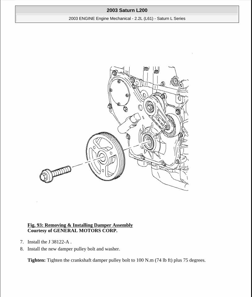
Fig. 93: Removing & Installing Damper Assembly Courtesy of GENERAL MOTORS CORP.
7. Install the J 38122-A .
8. Install the new damper pulley bolt and washer.
Tighten: Tighten the crankshaft damper pulley bolt to 100 N.m (74 lb ft) plus 75 degrees.
2003 Saturn L200
2003 ENGINE Engine Mechanical - 2.2L (L61) - Saturn L Series
steve
Monday, May 09, 2011 12:52:01 PM Page 131 © 2006 Mitchell Repair Information Company, LLC.

Fig. 94: Loosening Belt Tensioner To Remove/Install Drive Belt Courtesy of GENERAL MOTORS CORP.
9. Install the engine accessory drive belt.
2003 Saturn L200
2003 ENGINE Engine Mechanical - 2.2L (L61) - Saturn L Series
steve
Monday, May 09, 2011 12:52:01 PM Page 132 © 2006 Mitchell Repair Information Company, LLC.

Fig. 95: Removing/Installing Right Front Lower Splash Shield Courtesy of GENERAL MOTORS CORP.
10. Install the right wheel and splash shield.
11. Add the engine oil.
2003 Saturn L200
2003 ENGINE Engine Mechanical - 2.2L (L61) - Saturn L Series
steve
Monday, May 09, 2011 12:52:01 PM Page 133 © 2006 Mitchell Repair Information Company, LLC.

Fig. 96: Removing & Installing Air Cleaner Assembly Courtesy of GENERAL MOTORS CORP.
12. Install the air cleaner assembly.
13. Connect the negative battery cable.
Tighten: Tighten the battery terminal bolts to 17 N.m (13 lb ft).
TIMING CHAIN, SPROCKETS, AND/OR TENSIONER REPLACEMENT
Removal Procedure
2003 Saturn L200
2003 ENGINE Engine Mechanical - 2.2L (L61) - Saturn L Series
steve
Monday, May 09, 2011 12:52:01 PM Page 134 © 2006 Mitchell Repair Information Company, LLC.

Fig. 97: Pulling Camshafts Straight Up To Avoid Damaging The Cylinder Head Thrust Surfaces Courtesy of GENERAL MOTORS CORP.
1. Disconnect the negative battery cable.
2. Remove the front cover. Refer to Engine Front Cover Replacement (With Oil Pump Assembly).
2003 Saturn L200
2003 ENGINE Engine Mechanical - 2.2L (L61) - Saturn L Series
steve
Monday, May 09, 2011 12:52:01 PM Page 135 © 2006 Mitchell Repair Information Company, LLC.

Fig. 98: Removing & Installing Camshaft Cover Assembly Courtesy of GENERAL MOTORS CORP.
3. Remove the camshaft cover assembly. Refer to Camshaft Cover Replacement.
2003 Saturn L200
2003 ENGINE Engine Mechanical - 2.2L (L61) - Saturn L Series
steve
Monday, May 09, 2011 12:52:01 PM Page 136 © 2006 Mitchell Repair Information Company, LLC.

Fig. 99: Removing Timing Chain Tensioner Courtesy of GENERAL MOTORS CORP.
4. Remove timing chain tensioner.
IMPORTANT: The timing chain tensioner must be removed to unload the chain tension before the timing chain is removed. If it is not removed, the timing chain may become cocked and difficult to remove.
2003 Saturn L200
2003 ENGINE Engine Mechanical - 2.2L (L61) - Saturn L Series
steve
Monday, May 09, 2011 12:52:01 PM Page 137 © 2006 Mitchell Repair Information Company, LLC.

Fig. 100: Removing Upper Timing Chain Guide Courtesy of GENERAL MOTORS CORP.
5. Remove the upper timing chain guide.
2003 Saturn L200
2003 ENGINE Engine Mechanical - 2.2L (L61) - Saturn L Series
steve
Monday, May 09, 2011 12:52:01 PM Page 138 © 2006 Mitchell Repair Information Company, LLC.

Fig. 101: Removing Exhaust Camshaft Sprocket Courtesy of GENERAL MOTORS CORP.
6. Remove the exhaust camshaft sprocket and discard the bolt.
IMPORTANT: The camshaft sprocket bolt is not reusable. It is a torque-to-yield (TTY) bolt, and must be discarded to prevent premature failure.
2003 Saturn L200
2003 ENGINE Engine Mechanical - 2.2L (L61) - Saturn L Series
steve
Monday, May 09, 2011 12:52:01 PM Page 139 © 2006 Mitchell Repair Information Company, LLC.

Fig. 102: Removing Adjustable Timing Chain Guide Courtesy of GENERAL MOTORS CORP.
7. Remove the adjustable timing chain guide.
2003 Saturn L200
2003 ENGINE Engine Mechanical - 2.2L (L61) - Saturn L Series
steve
Monday, May 09, 2011 12:52:01 PM Page 140 © 2006 Mitchell Repair Information Company, LLC.

Fig. 103: Fixed Timing Chain Guide Access Plug Courtesy of GENERAL MOTORS CORP.
8. Remove the fixed timing chain guide access plug.
2003 Saturn L200
2003 ENGINE Engine Mechanical - 2.2L (L61) - Saturn L Series
steve
Monday, May 09, 2011 12:52:01 PM Page 141 © 2006 Mitchell Repair Information Company, LLC.

Fig. 104: Fixed Timing Chain Guide & Bolts Courtesy of GENERAL MOTORS CORP.
9. Remove the fixed timing chain guide.
2003 Saturn L200
2003 ENGINE Engine Mechanical - 2.2L (L61) - Saturn L Series
steve
Monday, May 09, 2011 12:52:01 PM Page 142 © 2006 Mitchell Repair Information Company, LLC.
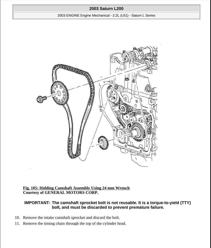
Fig. 105: Holding Camshaft Assembly Using 24 mm Wrench Courtesy of GENERAL MOTORS CORP.
10. Remove the intake camshaft sprocket and discard the bolt.
11. Remove the timing chain through the top of the cylinder head.
IMPORTANT: The camshaft sprocket bolt is not reusable. It is a torque-to-yield (TTY) bolt, and must be discarded to prevent premature failure.
2003 Saturn L200
2003 ENGINE Engine Mechanical - 2.2L (L61) - Saturn L Series
steve
Monday, May 09, 2011 12:52:01 PM Page 143 © 2006 Mitchell Repair Information Company, LLC.

Fig. 106: Installing Timing Chain Drive Sprocket Courtesy of GENERAL MOTORS CORP.
12. Remove the timing chain drive sprocket from the crankshaft.
2003 Saturn L200
2003 ENGINE Engine Mechanical - 2.2L (L61) - Saturn L Series
steve
Monday, May 09, 2011 12:52:01 PM Page 144 © 2006 Mitchell Repair Information Company, LLC.

Fig. 107: Removing & Installing Timing Chain Oiling Nozzle Courtesy of GENERAL MOTORS CORP.
13. Remove the timing chain oiling nozzle.
2003 Saturn L200
2003 ENGINE Engine Mechanical - 2.2L (L61) - Saturn L Series
steve
Monday, May 09, 2011 12:52:01 PM Page 145 © 2006 Mitchell Repair Information Company, LLC.

Fig. 108: Exploded View Of Timing Chain & Components Courtesy of GENERAL MOTORS CORP.
14. Inspect the timing chain guides for cracking or wear.
15. Inspect the timing chain tensioner shoe for wear.
16. Inspect the timing chain and sprockets for wear.
IMPORTANT: Replace the timing chain guides if wear exceeds 1.12 mm (0.045 in).
IMPORTANT: Replace the timing chain tensioner shoe if wear exceeds 1.12 mm (0.045 in).
2003 Saturn L200
2003 ENGINE Engine Mechanical - 2.2L (L61) - Saturn L Series
steve
Monday, May 09, 2011 12:52:01 PM Page 146 © 2006 Mitchell Repair Information Company, LLC.
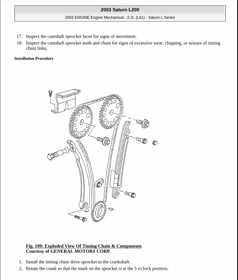
17. Inspect the camshaft sprocket faces for signs of movement.
18. Inspect the camshaft sprocket teeth and chain for signs of excessive wear, chipping, or seizure of timing chain links.
Installation Procedure
Fig. 109: Exploded View Of Timing Chain & Components Courtesy of GENERAL MOTORS CORP.
1. Install the timing chain drive sprocket to the crankshaft.
2. Rotate the crank so that the mark on the sprocket is at the 5 o'clock position.
2003 Saturn L200
2003 ENGINE Engine Mechanical - 2.2L (L61) - Saturn L Series
steve
Monday, May 09, 2011 12:52:01 PM Page 147 © 2006 Mitchell Repair Information Company, LLC.

Fig. 110: Positioning Intake Camshaft Courtesy of GENERAL MOTORS CORP.
3. Assemble the chain to the intake camshaft sprocket alignment copper link to the INT diamond timing mark on the camshaft sprocket.
2003 Saturn L200
2003 ENGINE Engine Mechanical - 2.2L (L61) - Saturn L Series
steve
Monday, May 09, 2011 12:52:01 PM Page 148 © 2006 Mitchell Repair Information Company, LLC.

Fig. 111: Rotating Assembly 90 Degrees To Allow The Chain To Fall Between The Cylinder Block Bosses Courtesy of GENERAL MOTORS CORP.
4. Lower the assembly through the chain housing opening on top of the cylinder head. Use care to make sure that the chain goes around both sides of the cylinder block bosses.
IMPORTANT: When lowering the timing chain rotate the assembly 90 degrees to allow the chain to fall between the cylinder block bosses, then rotate the assembly back so that the camshaft sprocket is facing forward.
2003 Saturn L200
2003 ENGINE Engine Mechanical - 2.2L (L61) - Saturn L Series
steve
Monday, May 09, 2011 12:52:01 PM Page 149 © 2006 Mitchell Repair Information Company, LLC.

Fig. 112: Setting Mark On The Timing Chain Drive Sprocket At 5 O'clock Position Courtesy of GENERAL MOTORS CORP.
5. Route the chain around the crankshaft sprocket and align the silver link to the timing mark.
6. Install the intake camshaft sprocket loosely onto the intake camshaft and install the new camshaft sprocket bolt finger tight. It is not necessary to align the sprocket-to-camshaft offset notch at this time.
IMPORTANT: The crankshaft sprocket timing mark will be at approximately the 5 o'clock position.
IMPORTANT: The camshaft sprocket bolt is not reusable. It is a torque-to-yield (TTY) bolt, and must be discarded to prevent premature failure.
2003 Saturn L200
2003 ENGINE Engine Mechanical - 2.2L (L61) - Saturn L Series
steve
Monday, May 09, 2011 12:52:01 PM Page 150 © 2006 Mitchell Repair Information Company, LLC.

Fig. 113: Removing Adjustable Timing Chain Guide Courtesy of GENERAL MOTORS CORP.
7. Install the adjustable timing chain guide through the opening on top of the cylinder head and install the chain guide bolt.
Tighten: Tighten the timing chain guide (adjustable) bolt to 10 N.m (89 lb in).
IMPORTANT: There is a 2nd design adjustable guide with a contact pad for the 2nd design notched tensioner. A 2nd design guide should be used only with 2nd design tensioner.
2003 Saturn L200
2003 ENGINE Engine Mechanical - 2.2L (L61) - Saturn L Series
steve
Monday, May 09, 2011 12:52:01 PM Page 151 © 2006 Mitchell Repair Information Company, LLC.

Fig. 114: Removing Exhaust Camshaft Sprocket Courtesy of GENERAL MOTORS CORP.
8. Install the exhaust camshaft sprocket loosely onto the exhaust camshaft with the timing mark on the sprocket aligned with the silver link and install the new camshaft sprocket bolt finger tight. It is not necessary to align the sprocket-to-camshaft offset notch at this time.
2003 Saturn L200
2003 ENGINE Engine Mechanical - 2.2L (L61) - Saturn L Series
steve
Monday, May 09, 2011 12:52:01 PM Page 152 © 2006 Mitchell Repair Information Company, LLC.

Fig. 115: Setting Mark On The Timing Chain Drive Sprocket At 5 O'clock Position Courtesy of GENERAL MOTORS CORP.
9. Align the camshaft sprocket-to-camshaft and tighten the camshaft bolt using the following procedure:
10. Ensure the sprocket timing mark is at the 5 o'clock position.
IMPORTANT: The camshaft sprocket bolt is not reusable. It is a torque-to-yield (TTY) bolt, and must be discarded to prevent premature failure.
NOTE: Do not rotate either camshaft more than half turn in either direction with crankshaft at top dead center (TDC). To do so may cause valve to piston contact resulting in a damaged valve and/or a damaged piston.
2003 Saturn L200
2003 ENGINE Engine Mechanical - 2.2L (L61) - Saturn L Series
steve
Monday, May 09, 2011 12:52:01 PM Page 153 © 2006 Mitchell Repair Information Company, LLC.

Fig. 116: Using 24 mm Wrench To Support The Camshaft Courtesy of GENERAL MOTORS CORP.
11. Rotate the intake camshaft using a 24 mm wrench on the flats of the camshaft until the sprocket-to-camshaft alignment notch seats.
12. When the sprocket seats on the camshaft, tighten the sprocket bolt finger tight.
13. Rotate the exhaust camshaft using a 24 mm wrench on the flats of the camshaft until the sprocket-to-camshaft alignment notch seats.
14. When the sprocket seats on the camshaft, tighten the sprocket bolt finger tight.
2003 Saturn L200
2003 ENGINE Engine Mechanical - 2.2L (L61) - Saturn L Series
steve
Monday, May 09, 2011 12:52:01 PM Page 154 © 2006 Mitchell Repair Information Company, LLC.
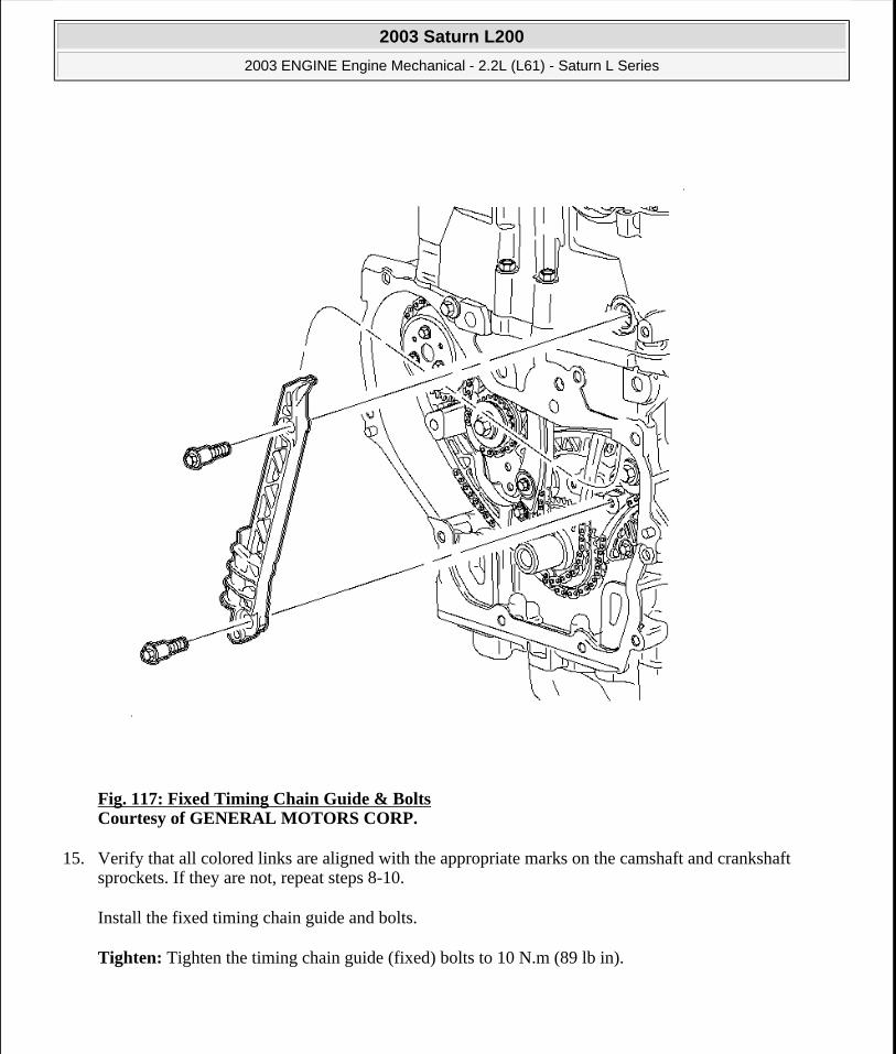
Fig. 117: Fixed Timing Chain Guide & Bolts Courtesy of GENERAL MOTORS CORP.
15. Verify that all colored links are aligned with the appropriate marks on the camshaft and crankshaft sprockets. If they are not, repeat steps 8-10.
Install the fixed timing chain guide and bolts.
Tighten: Tighten the timing chain guide (fixed) bolts to 10 N.m (89 lb in).
2003 Saturn L200
2003 ENGINE Engine Mechanical - 2.2L (L61) - Saturn L Series
steve
Monday, May 09, 2011 12:52:01 PM Page 155 © 2006 Mitchell Repair Information Company, LLC.

Fig. 118: Fixed Timing Chain Guide Access Plug Courtesy of GENERAL MOTORS CORP.
16. Install the fixed timing chain guide bolt access hole plug.
Tighten: Tighten the timing chain guide bolt access hole plug to 40 N.m (30 lb ft).
2003 Saturn L200
2003 ENGINE Engine Mechanical - 2.2L (L61) - Saturn L Series
steve
Monday, May 09, 2011 12:52:02 PM Page 156 © 2006 Mitchell Repair Information Company, LLC.
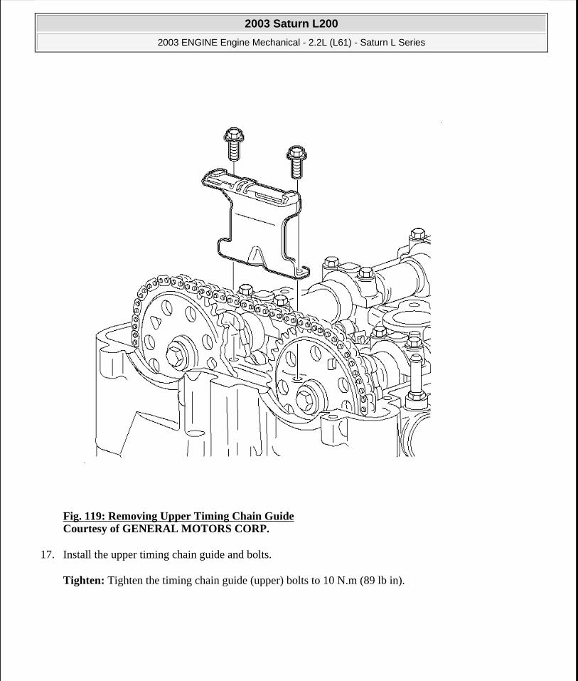
Fig. 119: Removing Upper Timing Chain Guide Courtesy of GENERAL MOTORS CORP.
17. Install the upper timing chain guide and bolts.
Tighten: Tighten the timing chain guide (upper) bolts to 10 N.m (89 lb in).
2003 Saturn L200
2003 ENGINE Engine Mechanical - 2.2L (L61) - Saturn L Series
steve
Monday, May 09, 2011 12:52:02 PM Page 157 © 2006 Mitchell Repair Information Company, LLC.

Fig. 120: Using 24 mm Wrench To Support The Camshaft Courtesy of GENERAL MOTORS CORP.
18. Tighten the intake and exhaust camshaft sprocket bolts.
Tighten: Tighten the camshaft sprocket bolts to 85 N.m (63 lb ft) +30 degrees.
NOTE: Use a 24 mm wrench to support the camshaft while applying torque to camshaft sprocket bolt. Do not torque camshaft bolts against timing chain, as it may damage the timing chain.
2003 Saturn L200
2003 ENGINE Engine Mechanical - 2.2L (L61) - Saturn L Series
steve
Monday, May 09, 2011 12:52:02 PM Page 158 © 2006 Mitchell Repair Information Company, LLC.

Fig. 121: Removing Timing Chain Tensioner Courtesy of GENERAL MOTORS CORP.
19. Install the sealing ring and tensioner assembly.
Tighten: Tighten the timing chain tensioner to 75 N.m (55 lb ft).
IMPORTANT: There is a 2nd design tensioner with a notch at the plunger end of the tensioner. This tensioner should be used only with the 2nd design adjustable guide.
2003 Saturn L200
2003 ENGINE Engine Mechanical - 2.2L (L61) - Saturn L Series
steve
Monday, May 09, 2011 12:52:02 PM Page 159 © 2006 Mitchell Repair Information Company, LLC.
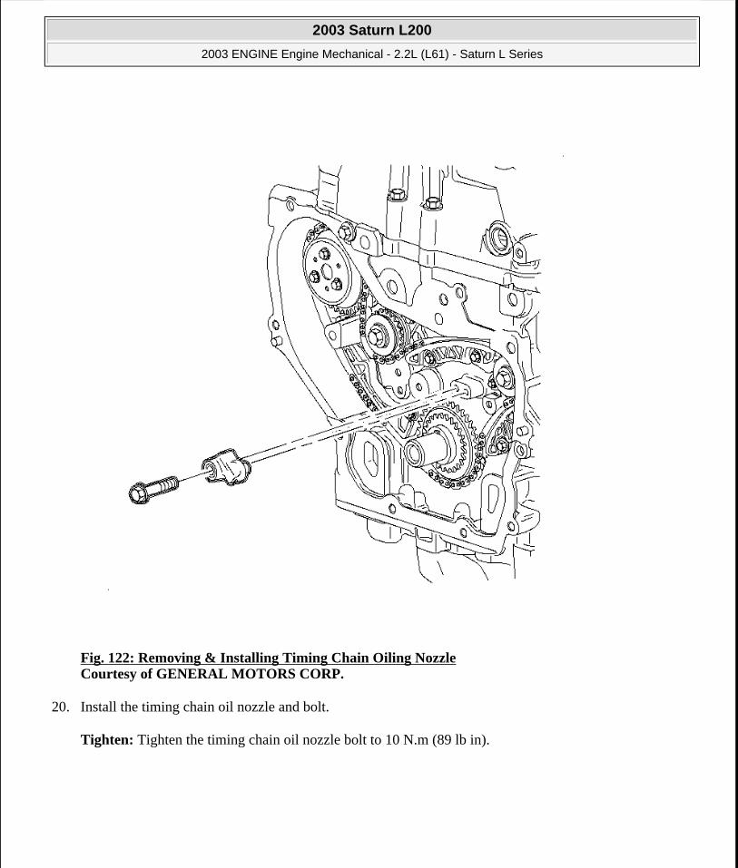
Fig. 122: Removing & Installing Timing Chain Oiling Nozzle Courtesy of GENERAL MOTORS CORP.
20. Install the timing chain oil nozzle and bolt.
Tighten: Tighten the timing chain oil nozzle bolt to 10 N.m (89 lb in).
2003 Saturn L200
2003 ENGINE Engine Mechanical - 2.2L (L61) - Saturn L Series
steve
Monday, May 09, 2011 12:52:02 PM Page 160 © 2006 Mitchell Repair Information Company, LLC.
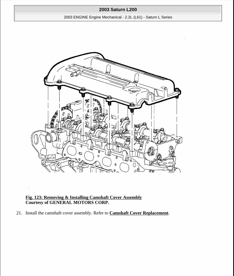
Fig. 123: Removing & Installing Camshaft Cover Assembly Courtesy of GENERAL MOTORS CORP.
21. Install the camshaft cover assembly. Refer to Camshaft Cover Replacement.
2003 Saturn L200
2003 ENGINE Engine Mechanical - 2.2L (L61) - Saturn L Series
steve
Monday, May 09, 2011 12:52:02 PM Page 161 © 2006 Mitchell Repair Information Company, LLC.

Fig. 124: Installing Engine Front Cover Courtesy of GENERAL MOTORS CORP.
22. Install the engine front cover. Refer to Engine Front Cover Replacement (With Oil Pump Assembly).
23. Connect the negative battery cable.
Tighten: Tighten the battery terminal bolts to 17 N.m (13 lb ft).
BALANCE SHAFT DRIVE TRAIN REPLACEMENT
Removal Procedure
2003 Saturn L200
2003 ENGINE Engine Mechanical - 2.2L (L61) - Saturn L Series
steve
Monday, May 09, 2011 12:52:02 PM Page 162 © 2006 Mitchell Repair Information Company, LLC.
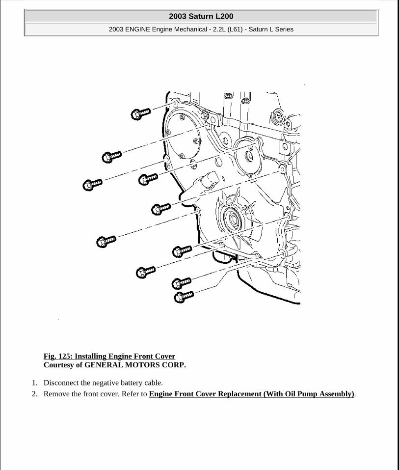
Fig. 125: Installing Engine Front Cover Courtesy of GENERAL MOTORS CORP.
1. Disconnect the negative battery cable.
2. Remove the front cover. Refer to Engine Front Cover Replacement (With Oil Pump Assembly).
2003 Saturn L200
2003 ENGINE Engine Mechanical - 2.2L (L61) - Saturn L Series
steve
Monday, May 09, 2011 12:52:02 PM Page 163 © 2006 Mitchell Repair Information Company, LLC.

Fig. 126: Removing & Installing Camshaft Cover Assembly Courtesy of GENERAL MOTORS CORP.
3. Remove the camshaft cover assembly. Refer to Camshaft Cover Replacement.
2003 Saturn L200
2003 ENGINE Engine Mechanical - 2.2L (L61) - Saturn L Series
steve
Monday, May 09, 2011 12:52:02 PM Page 164 © 2006 Mitchell Repair Information Company, LLC.

Fig. 127: Exploded View Of Timing Chain & Components Courtesy of GENERAL MOTORS CORP.
4. Remove the timing chain. Refer to Timing Chain, Sprockets, and/or Tensioner Replacement.
2003 Saturn L200
2003 ENGINE Engine Mechanical - 2.2L (L61) - Saturn L Series
steve
Monday, May 09, 2011 12:52:02 PM Page 165 © 2006 Mitchell Repair Information Company, LLC.

Fig. 128: Removing Balance Shaft Drive Chain Tensioner Courtesy of GENERAL MOTORS CORP.
5. Remove the balance shaft drive chain tensioner.
2003 Saturn L200
2003 ENGINE Engine Mechanical - 2.2L (L61) - Saturn L Series
steve
Monday, May 09, 2011 12:52:02 PM Page 166 © 2006 Mitchell Repair Information Company, LLC.

Fig. 129: Removing Adjustable Balance Shaft Chain Guise Courtesy of GENERAL MOTORS CORP.
6. Remove the adjustable balance shaft chain guide.
2003 Saturn L200
2003 ENGINE Engine Mechanical - 2.2L (L61) - Saturn L Series
steve
Monday, May 09, 2011 12:52:02 PM Page 167 © 2006 Mitchell Repair Information Company, LLC.

Fig. 130: Removing Small Balance Shaft Chain Guide Courtesy of GENERAL MOTORS CORP.
7. Remove the small balance shaft chain guide.
2003 Saturn L200
2003 ENGINE Engine Mechanical - 2.2L (L61) - Saturn L Series
steve
Monday, May 09, 2011 12:52:02 PM Page 168 © 2006 Mitchell Repair Information Company, LLC.
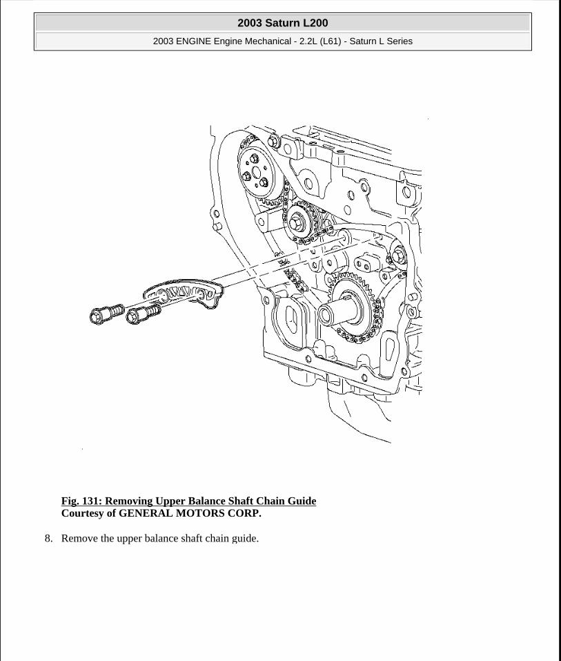
Fig. 131: Removing Upper Balance Shaft Chain Guide Courtesy of GENERAL MOTORS CORP.
8. Remove the upper balance shaft chain guide.
2003 Saturn L200
2003 ENGINE Engine Mechanical - 2.2L (L61) - Saturn L Series
steve
Monday, May 09, 2011 12:52:02 PM Page 169 © 2006 Mitchell Repair Information Company, LLC.

Fig. 132: Removing Balance Shaft Drive Chain Courtesy of GENERAL MOTORS CORP.
9. Remove the balance shaft drive chain.
10. Remove the crankshaft drive sprocket.
IMPORTANT: Push on the chain between the water pump and the camshaft sprockets so that all of the slack is between these 2 points. This will allow easier removal of the chain.
2003 Saturn L200
2003 ENGINE Engine Mechanical - 2.2L (L61) - Saturn L Series
steve
Monday, May 09, 2011 12:52:02 PM Page 170 © 2006 Mitchell Repair Information Company, LLC.

Fig. 133: View of Balance Shaft Drive Chain Guides Courtesy of GENERAL MOTORS CORP.
11. Inspect the balance shaft drive chain guides for cracking or wear.
12. Inspect the balance shaft drive chain tensioner shoe for excessive wear.
IMPORTANT: Replace the balance shaft drive chain guide if wear exceeds 1.12 mm (0.045 in).
IMPORTANT: Replace the balance shaft drive chain tensioner shoe if wear exceeds 1.12 mm (0.045 in).
2003 Saturn L200
2003 ENGINE Engine Mechanical - 2.2L (L61) - Saturn L Series
steve
Monday, May 09, 2011 12:52:02 PM Page 171 © 2006 Mitchell Repair Information Company, LLC.

13. Inspect the balance shaft drive chain and sprockets for wear.
14. Inspect the camshaft sprocket faces for signs of movement.
15. Inspect the alignment notch in the camshaft for cracking or damage.
16. Inspect the water pump, crankshaft, and balance shaft sprocket teeth and chain for signs of excessive wear, chipping, or seizure of the balance shaft drive chain links.
Installation Procedure
Fig. 134: Identifying Balance Shaft Timing Marks Courtesy of GENERAL MOTORS CORP.
IMPORTANT: If the balance shafts are not correctly timed to the crankshaft the engine
2003 Saturn L200
2003 ENGINE Engine Mechanical - 2.2L (L61) - Saturn L Series
steve
Monday, May 09, 2011 12:52:02 PM Page 172 © 2006 Mitchell Repair Information Company, LLC.

1. Orient the timing marks on the balance shafts.
1. The intake side balance shaft timing mark should be pointing up.
2. The exhaust side balance shaft timing mark should be pointing down.
2. With the balance shafts oriented, install the balance shaft crankcase sprocket onto the crankshaft.
3. Place the number 1 piston at top dead center (TDC).
may vibrate or make excessive noise.
IMPORTANT: The crankshaft keyway slot will be pointing up (12 o'clock position) when set at TDC.
2003 Saturn L200
2003 ENGINE Engine Mechanical - 2.2L (L61) - Saturn L Series
steve
Monday, May 09, 2011 12:52:02 PM Page 173 © 2006 Mitchell Repair Information Company, LLC.

Fig. 135: Identifying Balance Shaft Chain Colored LinksCourtesy of GENERAL MOTORS CORP.
4. Install the balance shaft chain with the colored links lined up with the marks on the balance shaft sprockets with the mark on the crankshaft sprocket.
1. Orient the chain so that the copper (1) and chrome (2) links are visible.
2. Place the copper colored link (1) onto the timing mark on the intake side balance shaft sprocket.
3. Working clockwise along the chain, place the first chrome link in line with the timing mark on the crankshaft sprocket.
4. Align the last chrome link with the timing mark on the exhaust side balance shaft sprocket.
IMPORTANT: There is 1 copper link (1) and 2 chrome links (2) on the balance shaft chain.
2003 Saturn L200
2003 ENGINE Engine Mechanical - 2.2L (L61) - Saturn L Series
steve
Monday, May 09, 2011 12:52:02 PM Page 174 © 2006 Mitchell Repair Information Company, LLC.

Fig. 136: Installing Upper Chain Guide & Bolt Courtesy of GENERAL MOTORS CORP.
5. Install the upper chain guide and bolt.
Tighten: Tighten the balance shaft chain guide (upper) bolts to 10 N.m (89 lb in).
2003 Saturn L200
2003 ENGINE Engine Mechanical - 2.2L (L61) - Saturn L Series
steve
Monday, May 09, 2011 12:52:02 PM Page 175 © 2006 Mitchell Repair Information Company, LLC.

Fig. 137: Installing Small Chain Guide & Bolts Courtesy of GENERAL MOTORS CORP.
6. Install the small chain guide and bolt.
7. Tighten the chain guide bolt.
Tighten: Tighten the balance shaft chain guide (fixed) bolts to 10 N.m (89 lb in).
2003 Saturn L200
2003 ENGINE Engine Mechanical - 2.2L (L61) - Saturn L Series
steve
Monday, May 09, 2011 12:52:02 PM Page 176 © 2006 Mitchell Repair Information Company, LLC.
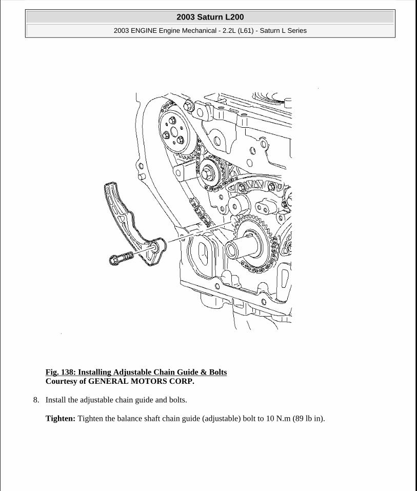
Fig. 138: Installing Adjustable Chain Guide & Bolts Courtesy of GENERAL MOTORS CORP.
8. Install the adjustable chain guide and bolts.
Tighten: Tighten the balance shaft chain guide (adjustable) bolt to 10 N.m (89 lb in).
2003 Saturn L200
2003 ENGINE Engine Mechanical - 2.2L (L61) - Saturn L Series
steve
Monday, May 09, 2011 12:52:02 PM Page 177 © 2006 Mitchell Repair Information Company, LLC.
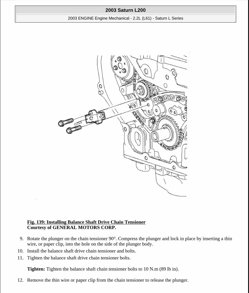
Fig. 139: Installing Balance Shaft Drive Chain Tensioner Courtesy of GENERAL MOTORS CORP.
9. Rotate the plunger on the chain tensioner 90°. Compress the plunger and lock in place by inserting a thin wire, or paper clip, into the hole on the side of the plunger body.
10. Install the balance shaft drive chain tensioner and bolts.
11. Tighten the balance shaft drive chain tensioner bolts.
Tighten: Tighten the balance shaft chain tensioner bolts to 10 N.m (89 lb in).
12. Remove the thin wire or paper clip from the chain tensioner to release the plunger.
2003 Saturn L200
2003 ENGINE Engine Mechanical - 2.2L (L61) - Saturn L Series
steve
Monday, May 09, 2011 12:52:02 PM Page 178 © 2006 Mitchell Repair Information Company, LLC.

Fig. 140: Exploded View Of Timing Chain & Components Courtesy of GENERAL MOTORS CORP.
13. Install the timing chain. Refer to Timing Chain, Sprockets, and/or Tensioner Replacement.
2003 Saturn L200
2003 ENGINE Engine Mechanical - 2.2L (L61) - Saturn L Series
steve
Monday, May 09, 2011 12:52:02 PM Page 179 © 2006 Mitchell Repair Information Company, LLC.

Fig. 141: Removing & Installing Camshaft Cover Assembly Courtesy of GENERAL MOTORS CORP.
14. Install the camshaft cover. Refer to Camshaft Cover Replacement.
Tighten: Tighten the camshaft cover bolts to 10 N.m (89 lb in).
2003 Saturn L200
2003 ENGINE Engine Mechanical - 2.2L (L61) - Saturn L Series
steve
Monday, May 09, 2011 12:52:02 PM Page 180 © 2006 Mitchell Repair Information Company, LLC.
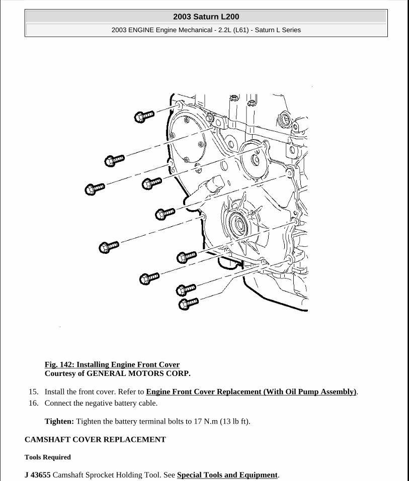
Fig. 142: Installing Engine Front Cover Courtesy of GENERAL MOTORS CORP.
15. Install the front cover. Refer to Engine Front Cover Replacement (With Oil Pump Assembly).
16. Connect the negative battery cable.
Tighten: Tighten the battery terminal bolts to 17 N.m (13 lb ft).
CAMSHAFT COVER REPLACEMENT
Tools Required
J 43655 Camshaft Sprocket Holding Tool. See Special Tools and Equipment.
2003 Saturn L200
2003 ENGINE Engine Mechanical - 2.2L (L61) - Saturn L Series
steve
Monday, May 09, 2011 12:52:02 PM Page 181 © 2006 Mitchell Repair Information Company, LLC.

The L61 engine camshafts, rocker arms, lash adjusters, valve springs, and seals can be serviced without removing the exhaust system, vibration damper, front mount, or front cover. The following procedure must be followed to prevent damage to the camshafts, lash adjusters, cylinder head, and lower timing chain guides.
Removal Procedure
Fig. 143: Removing & Installing Camshaft Cover Assembly Courtesy of GENERAL MOTORS CORP.
1. Disconnect the negative battery cable.
2. Remove the ignition coil, PCV fresh air hose, ground strap, fuel line, harness bracket, and cam cover assembly.
3. Remove the power steering pump if removing the intake camshaft.
NOTE: To avoid valve piston contact, No. 1 cylinder piston must be positioned at
2003 Saturn L200
2003 ENGINE Engine Mechanical - 2.2L (L61) - Saturn L Series
steve
Monday, May 09, 2011 12:52:02 PM Page 182 © 2006 Mitchell Repair Information Company, LLC.

4. Locate the No. 1 piston to approximately 60° before top dead center. The diamond shaped hole on the intake camshaft sprocket is at the 12 o'clock position. Spark plugs can be removed to ease the rotation effort.
5. Remove the upper timing chain guide.
6. Remove the front camshaft caps.
approximately 60 degrees before-top dead center (BTDC). Pistons are properly positioned when the diamond shaped hole on the intake camshaft sprocket is located at 12 o'clock.
IMPORTANT: To rotate the camshafts, use a 24 mm open-end wrench on the camshaft flats. Camshafts should be rotated in a clockwise direction only, facing the camshaft sprockets from the passenger side of the vehicle.
2003 Saturn L200
2003 ENGINE Engine Mechanical - 2.2L (L61) - Saturn L Series
steve
Monday, May 09, 2011 12:52:02 PM Page 183 © 2006 Mitchell Repair Information Company, LLC.

Fig. 144: Installing Camshaft Sprocket Holding Tool Courtesy of GENERAL MOTORS CORP.
7. Install the J 43655 through the sprocket holes from the timing chain side of the sprocket towards the rear of the engine. See Special Tools and Equipment.
8. With the guide pins installed in the sprocket, align the guide pins into the slot on the support head.
Tighten: Tighten the support plate-to-engine block to 10 N.m (89 lb in).
IMPORTANT: Lubricate the sprocket pins with clean motor oil. This will allow the sprockets to easily slide on the sprocket pins. Align the diamond shaped hole straight up on the intake camshaft.
2003 Saturn L200
2003 ENGINE Engine Mechanical - 2.2L (L61) - Saturn L Series
steve
Monday, May 09, 2011 12:52:02 PM Page 184 © 2006 Mitchell Repair Information Company, LLC.

9. Install the wing nuts and tighten.
Fig. 145: Holding Camshaft In Place Using A 24 mm Open End Wrench Courtesy of GENERAL MOTORS CORP.
10. Hold each camshaft in place using a 24 mm open end wrench and carefully remove the camshaft timing sprocket retaining bolts and washers. Discard the torque-to-yield (TTY) bolt.
2003 Saturn L200
2003 ENGINE Engine Mechanical - 2.2L (L61) - Saturn L Series
steve
Monday, May 09, 2011 12:52:02 PM Page 185 © 2006 Mitchell Repair Information Company, LLC.

Fig. 146: Removing Camshaft Bearing Cap Bolts Courtesy of GENERAL MOTORS CORP.
11. Slide the camshaft sprockets away from the camshaft.
12. To release the spring tension, rotate the camshaft being serviced.
13. Uniformly loosen and remove the remaining camshaft bearing cap bolts.
IMPORTANT: When sliding the timing chain and sprockets onto the guide pins, be sure the timing chain is positioned properly on the adjustable and fixed guide or guide damage will occur. Care should be taken when removing the camshaft sprockets from the camshafts.
2003 Saturn L200
2003 ENGINE Engine Mechanical - 2.2L (L61) - Saturn L Series
steve
Monday, May 09, 2011 12:52:02 PM Page 186 © 2006 Mitchell Repair Information Company, LLC.

Fig. 147: Pulling Camshafts Straight Up To Avoid Damaging The Cylinder Head Thrust Surfaces Courtesy of GENERAL MOTORS CORP.
14. Carefully pull the camshafts straight up to avoid damaging the cylinder head thrust surface when removing the camshafts.
Installation Procedure
IMPORTANT: Camshafts are spring loaded and may rotate.
2003 Saturn L200
2003 ENGINE Engine Mechanical - 2.2L (L61) - Saturn L Series
steve
Monday, May 09, 2011 12:52:02 PM Page 187 © 2006 Mitchell Repair Information Company, LLC.

Fig. 148: Aligning Camshaft Slot In Line With The Notch On The Sprockets Courtesy of GENERAL MOTORS CORP.
1. Lubricate the camshaft bearing journals with clean engine oil and install both camshafts and all bearing caps, except the front cap on each camshaft.
2. When installing camshafts, attempt to position the camshaft slot up with the notches on the camshaft sprockets.
3. Install all bearing caps except the front caps and the rear intake camshaft cap, if serviced. Tighten down the bearing caps uniformly.
NOTE: Refer to FASTENER NOTICE in Cautions and Notices.
2003 Saturn L200
2003 ENGINE Engine Mechanical - 2.2L (L61) - Saturn L Series
steve
Monday, May 09, 2011 12:52:02 PM Page 188 © 2006 Mitchell Repair Information Company, LLC.

Tighten: Tighten the camshaft bearing cap bolts to 10 N.m (89 lb in).
Fig. 149: Holding Camshaft In Place Using A 24 mm Open End Wrench Courtesy of GENERAL MOTORS CORP.
4. Slide the camshaft sprockets and the timing chain on the guide pins toward the camshafts. Rotate the camshafts with a 24 mm open-end wrench to properly align the camshafts and sprockets.
5. Install the new camshaft sprocket bolt and tighten. This will pull the camshaft sprockets into the cams. Hold the camshaft with a 24 mm open end wrench during tightening.
Tighten: Tighten the camshaft sprocket bolts to 85 N.m (63 lb ft) plus 30 degrees.
6. Remove the J 43655 . See Special Tools and Equipment.
2003 Saturn L200
2003 ENGINE Engine Mechanical - 2.2L (L61) - Saturn L Series
steve
Monday, May 09, 2011 12:52:02 PM Page 189 © 2006 Mitchell Repair Information Company, LLC.

7. Install the front camshaft caps.
Tighten: Tighten the camshaft bearing cap bolts to 10 N.m (89 lb in).
Fig. 150: Applying LOCTITE 242® & Installing Upper Timing Chain Guide Bolts Courtesy of GENERAL MOTORS CORP.
8. Install the upper timing chain guide.
Tighten: Tighten the timing chain guide (upper) bolts to 10 N.m (89 lb in).
IMPORTANT: Apply LOCTITE 242® to the upper timing chain guide bolts.
2003 Saturn L200
2003 ENGINE Engine Mechanical - 2.2L (L61) - Saturn L Series
steve
Monday, May 09, 2011 12:52:02 PM Page 190 © 2006 Mitchell Repair Information Company, LLC.

9. Install the rear intake camshaft bearing cap.
Tighten: Tighten the intake camshaft rear bearing cap bolts to 25 N.m (18 lb ft).
10. Install the power steering pump.
Tighten: Tighten the power steering pump bolts to 25 N.m (18 lb ft).
11. Install the ignition coil, PCV fresh air hose, ground strap, fuel line, harness bracket, and cam cover assembly.
12. Connect the negative battery cable.
VALVE ROCKER ARM AND VALVE LASH ADJUSTER REPLACEMENT
Tools Required
J 43655 Camshaft Sprocket Holding Tool. See Special Tools and Equipment.
2003 Saturn L200
2003 ENGINE Engine Mechanical - 2.2L (L61) - Saturn L Series
steve
Monday, May 09, 2011 12:52:02 PM Page 191 © 2006 Mitchell Repair Information Company, LLC.

Fig. 151: Pulling Camshafts Straight Up To Avoid Damaging The Cylinder Head Thrust Surfaces Courtesy of GENERAL MOTORS CORP.
The L61 engine camshafts, rocker arms, valve lash adjusters, valve springs, and seals can be serviced without removing the exhaust system, vibration damper, front mount, or front cover. The following procedure must be followed to prevent damage to the camshafts, lash adjusters, cylinder head, and lower timing chain guides.
Removal Procedure
IMPORTANT: The J 43655 Camshaft Sprocket Holding Tool must be used to remove one or both camshafts at the same time. The engine's crankshaft can not be rotated with the camshafts removed.
2003 Saturn L200
2003 ENGINE Engine Mechanical - 2.2L (L61) - Saturn L Series
steve
Monday, May 09, 2011 12:52:02 PM Page 192 © 2006 Mitchell Repair Information Company, LLC.
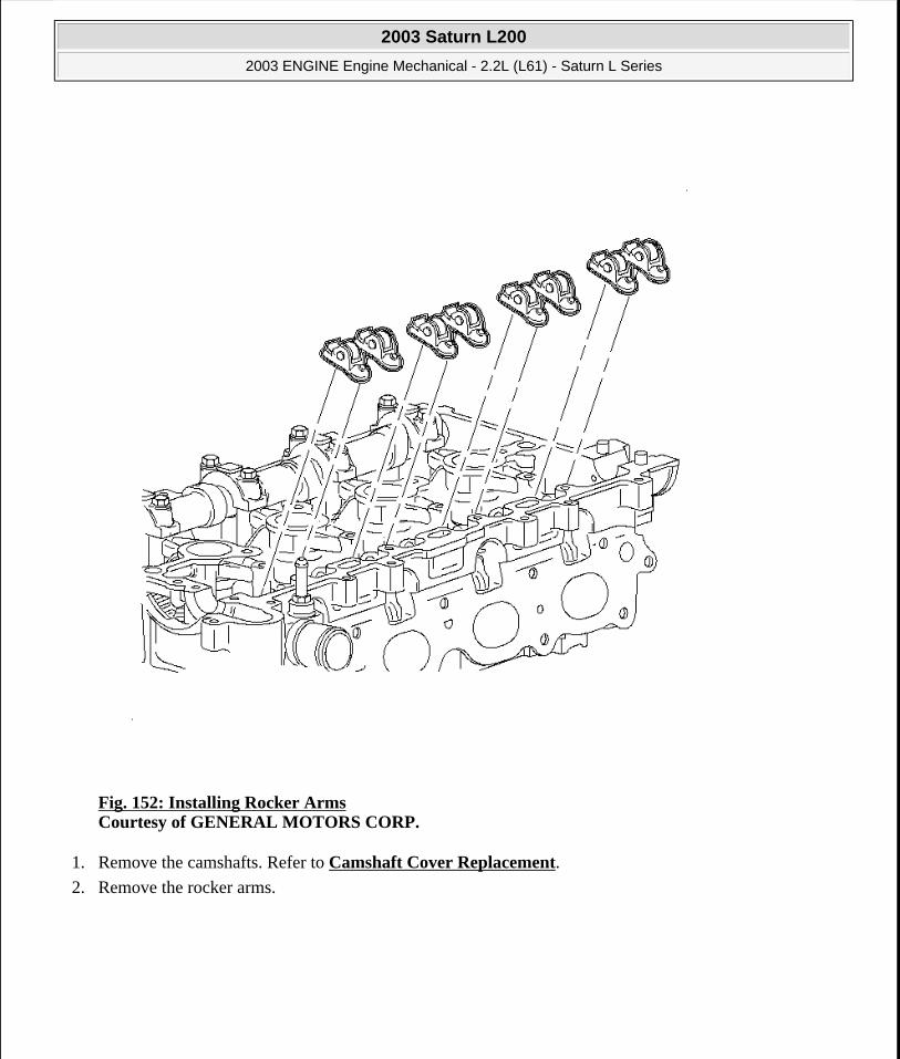
Fig. 152: Installing Rocker Arms Courtesy of GENERAL MOTORS CORP.
1. Remove the camshafts. Refer to Camshaft Cover Replacement.
2. Remove the rocker arms.
2003 Saturn L200
2003 ENGINE Engine Mechanical - 2.2L (L61) - Saturn L Series
steve
Monday, May 09, 2011 12:52:02 PM Page 193 © 2006 Mitchell Repair Information Company, LLC.

Fig. 153: Removing/Installing Lash Adjusters Courtesy of GENERAL MOTORS CORP.
3. Remove the valve lash adjusters.
Installation Procedure
2003 Saturn L200
2003 ENGINE Engine Mechanical - 2.2L (L61) - Saturn L Series
steve
Monday, May 09, 2011 12:52:02 PM Page 194 © 2006 Mitchell Repair Information Company, LLC.

Fig. 154: Installing Valve Lash Adjusters Courtesy of GENERAL MOTORS CORP.
1. Install the valve lash adjusters.
2003 Saturn L200
2003 ENGINE Engine Mechanical - 2.2L (L61) - Saturn L Series
steve
Monday, May 09, 2011 12:52:02 PM Page 195 © 2006 Mitchell Repair Information Company, LLC.

Fig. 155: Installing Rocker Arms Courtesy of GENERAL MOTORS CORP.
2. Install the rocker arms.
2003 Saturn L200
2003 ENGINE Engine Mechanical - 2.2L (L61) - Saturn L Series
steve
Monday, May 09, 2011 12:52:02 PM Page 196 © 2006 Mitchell Repair Information Company, LLC.

Fig. 156: Pulling Camshafts Straight Up To Avoid Damaging The Cylinder Head Thrust Surfaces Courtesy of GENERAL MOTORS CORP.
3. Install the camshafts. Refer to Camshaft Cover Replacement.
NOTE: After cylinder block, head, or lifter replacement, it will be necessary to allow the engine to idle for 3-5 minutes. If the lifters are noisy, warm the engine up at less than 200 RPM. After the coolant temperature has reached approximately 85°C (185°F), cycle the engine RPM from idle to 300 RPM for approximately 10 minutes or drive the vehicle 8 kilometers (5 miles) to purge the air. If the air cannot be purged, the faulty lifters will have to be replaced.
2003 Saturn L200
2003 ENGINE Engine Mechanical - 2.2L (L61) - Saturn L Series
steve
Monday, May 09, 2011 12:52:02 PM Page 197 © 2006 Mitchell Repair Information Company, LLC.
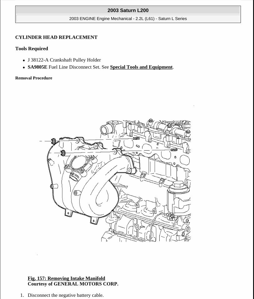
CYLINDER HEAD REPLACEMENT
Tools Required
J 38122-A Crankshaft Pulley Holder
SA9805E Fuel Line Disconnect Set. See Special Tools and Equipment.
Removal Procedure
Fig. 157: Removing Intake Manifold Courtesy of GENERAL MOTORS CORP.
1. Disconnect the negative battery cable.
2003 Saturn L200
2003 ENGINE Engine Mechanical - 2.2L (L61) - Saturn L Series
steve
Monday, May 09, 2011 12:52:02 PM Page 198 © 2006 Mitchell Repair Information Company, LLC.

2. Remove the intake manifold. Refer to Intake Manifold Replacement.
Fig. 158: Removing Exhaust Manifold Pipe Courtesy of GENERAL MOTORS CORP.
3. Remove the exhaust manifold flange bolts.
4. Remove the coolant reservoir cap.
5. Raise the vehicle. Refer to Lifting and Jacking the Vehicle in General Information.
6. Remove the exhaust manifold down pipe to catalytic convertor bolts.
7. Disconnect the exhaust down pipe from the exhaust manifold flange studs and secure the exhaust pipe to the under-carriage.
2003 Saturn L200
2003 ENGINE Engine Mechanical - 2.2L (L61) - Saturn L Series
steve
Monday, May 09, 2011 12:52:02 PM Page 199 © 2006 Mitchell Repair Information Company, LLC.
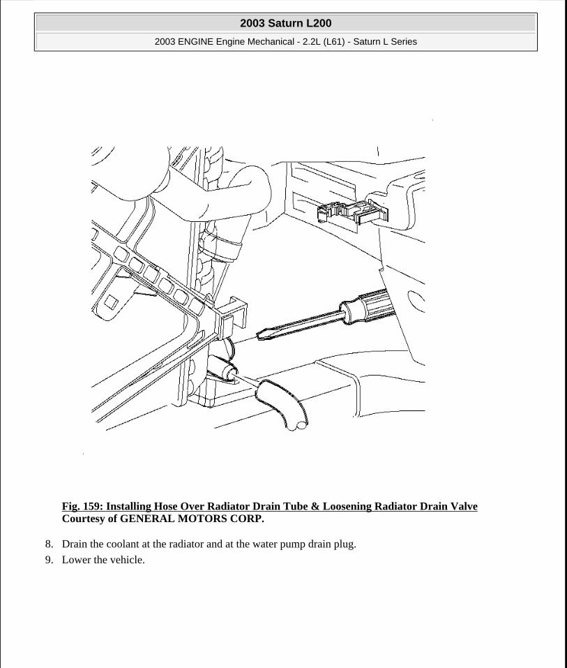
Fig. 159: Installing Hose Over Radiator Drain Tube & Loosening Radiator Drain Valve Courtesy of GENERAL MOTORS CORP.
8. Drain the coolant at the radiator and at the water pump drain plug.
9. Lower the vehicle.
2003 Saturn L200
2003 ENGINE Engine Mechanical - 2.2L (L61) - Saturn L Series
steve
Monday, May 09, 2011 12:52:02 PM Page 200 © 2006 Mitchell Repair Information Company, LLC.
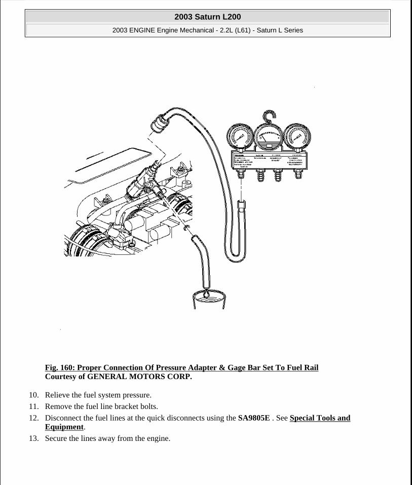
Fig. 160: Proper Connection Of Pressure Adapter & Gage Bar Set To Fuel Rail Courtesy of GENERAL MOTORS CORP.
10. Relieve the fuel system pressure.
11. Remove the fuel line bracket bolts.
12. Disconnect the fuel lines at the quick disconnects using the SA9805E . See Special Tools and Equipment.
13. Secure the lines away from the engine.
2003 Saturn L200
2003 ENGINE Engine Mechanical - 2.2L (L61) - Saturn L Series
steve
Monday, May 09, 2011 12:52:02 PM Page 201 © 2006 Mitchell Repair Information Company, LLC.
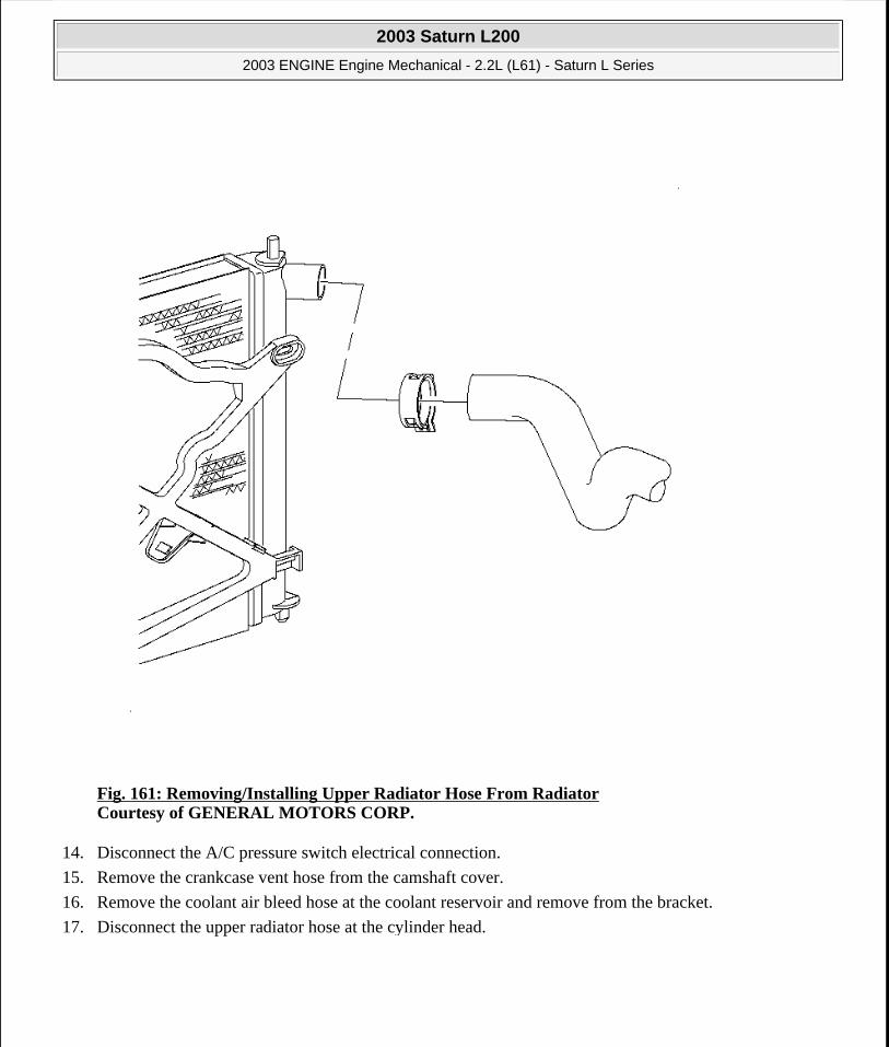
Fig. 161: Removing/Installing Upper Radiator Hose From Radiator Courtesy of GENERAL MOTORS CORP.
14. Disconnect the A/C pressure switch electrical connection.
15. Remove the crankcase vent hose from the camshaft cover.
16. Remove the coolant air bleed hose at the coolant reservoir and remove from the bracket.
17. Disconnect the upper radiator hose at the cylinder head.
2003 Saturn L200
2003 ENGINE Engine Mechanical - 2.2L (L61) - Saturn L Series
steve
Monday, May 09, 2011 12:52:02 PM Page 202 © 2006 Mitchell Repair Information Company, LLC.
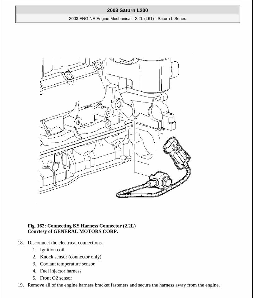
Fig. 162: Connecting KS Harness Connector (2.2L) Courtesy of GENERAL MOTORS CORP.
18. Disconnect the electrical connections.
1. Ignition coil
2. Knock sensor (connector only)
3. Coolant temperature sensor
4. Fuel injector harness
5. Front O2 sensor
19. Remove all of the engine harness bracket fasteners and secure the harness away from the engine.
2003 Saturn L200
2003 ENGINE Engine Mechanical - 2.2L (L61) - Saturn L Series
steve
Monday, May 09, 2011 12:52:02 PM Page 203 © 2006 Mitchell Repair Information Company, LLC.

Fig. 163: Installing Ignition Module Assembly Courtesy of GENERAL MOTORS CORP.
20. Remove the ignition coil.
21. Remove the power steering pump and secure away from the engine. Do not remove the hydraulic lines.
2003 Saturn L200
2003 ENGINE Engine Mechanical - 2.2L (L61) - Saturn L Series
steve
Monday, May 09, 2011 12:52:02 PM Page 204 © 2006 Mitchell Repair Information Company, LLC.
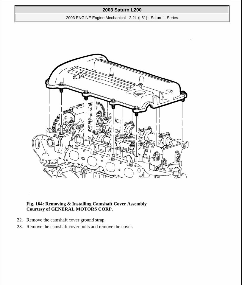
Fig. 164: Removing & Installing Camshaft Cover Assembly Courtesy of GENERAL MOTORS CORP.
22. Remove the camshaft cover ground strap.
23. Remove the camshaft cover bolts and remove the cover.
2003 Saturn L200
2003 ENGINE Engine Mechanical - 2.2L (L61) - Saturn L Series
steve
Monday, May 09, 2011 12:52:02 PM Page 205 © 2006 Mitchell Repair Information Company, LLC.

Fig. 165: Removing Upper Timing Chain Guide Courtesy of GENERAL MOTORS CORP.
24. Remove the upper timing chain guide.
2003 Saturn L200
2003 ENGINE Engine Mechanical - 2.2L (L61) - Saturn L Series
steve
Monday, May 09, 2011 12:52:02 PM Page 206 © 2006 Mitchell Repair Information Company, LLC.

Fig. 166: Removing Timing Chain Tensioner Courtesy of GENERAL MOTORS CORP.
25. Remove the upper timing chain tensioner.
IMPORTANT: The timing chain tensioner must be removed to unload the chain tension before the timing chain is removed. If it is not, the timing chain may become misaligned and difficult to remove.
2003 Saturn L200
2003 ENGINE Engine Mechanical - 2.2L (L61) - Saturn L Series
steve
Monday, May 09, 2011 12:52:02 PM Page 207 © 2006 Mitchell Repair Information Company, LLC.

Fig. 167: Removing Camshaft Sprockets Courtesy of GENERAL MOTORS CORP.
26. Remove the camshaft sprocket bolts using a 24 mm open-end wrench to counter-hold the camshaft while loosening the bolts. Discard the bolts.
27. Attach a medium size cable tie to the timing chain to prevent the chain from falling into the oil pan.
28. Remove the camshaft sprockets.
IMPORTANT: Do not allow any load onto the timing chain upon loosening the camshaft sprocket bolts.
2003 Saturn L200
2003 ENGINE Engine Mechanical - 2.2L (L61) - Saturn L Series
steve
Monday, May 09, 2011 12:52:02 PM Page 208 © 2006 Mitchell Repair Information Company, LLC.

Fig. 168: Fixed Timing Chain Guide Access Plug Courtesy of GENERAL MOTORS CORP.
29. Remove the plug to gain access to the fixed timing chain guide bolt.
2003 Saturn L200
2003 ENGINE Engine Mechanical - 2.2L (L61) - Saturn L Series
steve
Monday, May 09, 2011 12:52:02 PM Page 209 © 2006 Mitchell Repair Information Company, LLC.
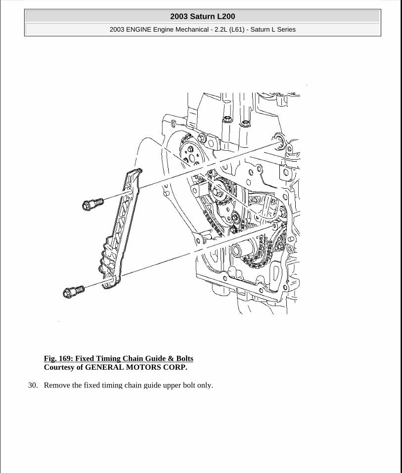
Fig. 169: Fixed Timing Chain Guide & Bolts Courtesy of GENERAL MOTORS CORP.
30. Remove the fixed timing chain guide upper bolt only.
2003 Saturn L200
2003 ENGINE Engine Mechanical - 2.2L (L61) - Saturn L Series
steve
Monday, May 09, 2011 12:52:02 PM Page 210 © 2006 Mitchell Repair Information Company, LLC.

Fig. 170: Removing Cylinder Head Bolts Using Loosening Sequence Courtesy of GENERAL MOTORS CORP.
31. Remove the cylinder head to block bolts using the loosening sequence.
2003 Saturn L200
2003 ENGINE Engine Mechanical - 2.2L (L61) - Saturn L Series
steve
Monday, May 09, 2011 12:52:02 PM Page 211 © 2006 Mitchell Repair Information Company, LLC.

Fig. 171: Inspecting Timing Chain Guide Courtesy of GENERAL MOTORS CORP.
32. Lift the cylinder head from the dowels on the engine block and place the cylinder head on wooden blocks or a bench. If the cylinder head is difficult to lift off, use a pry bar at the designated pry points.
NOTE: Be careful not to damage the aluminum the aluminum cylinder head and block gasket sealing surfaces when removing the cylinder head or during cleaning.
2003 Saturn L200
2003 ENGINE Engine Mechanical - 2.2L (L61) - Saturn L Series
steve
Monday, May 09, 2011 12:52:02 PM Page 212 © 2006 Mitchell Repair Information Company, LLC.

Fig. 172: Removing/Installing Right Front Lower Splash Shield Courtesy of GENERAL MOTORS CORP.
33. Raise the vehicle. Refer to Lifting and Jacking the Vehicle in General Information.
34. Remove the right front wheel.
35. Remove the lower splash shield.
2003 Saturn L200
2003 ENGINE Engine Mechanical - 2.2L (L61) - Saturn L Series
steve
Monday, May 09, 2011 12:52:02 PM Page 213 © 2006 Mitchell Repair Information Company, LLC.

Fig. 173: Loosening Belt Tensioner To Remove/Install Drive Belt Courtesy of GENERAL MOTORS CORP.
36. Remove the accessory drive belt.
2003 Saturn L200
2003 ENGINE Engine Mechanical - 2.2L (L61) - Saturn L Series
steve
Monday, May 09, 2011 12:52:02 PM Page 214 © 2006 Mitchell Repair Information Company, LLC.
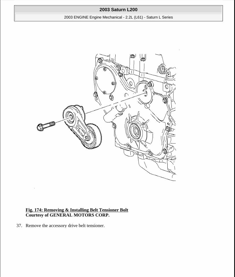
Fig. 174: Removing & Installing Belt Tensioner Bolt Courtesy of GENERAL MOTORS CORP.
37. Remove the accessory drive belt tensioner.
2003 Saturn L200
2003 ENGINE Engine Mechanical - 2.2L (L61) - Saturn L Series
steve
Monday, May 09, 2011 12:52:02 PM Page 215 © 2006 Mitchell Repair Information Company, LLC.

Fig. 175: Removing & Installing Harmonic Balancer Using Holder On Damper Assembly Courtesy of GENERAL MOTORS CORP.
38. Remove the suction liquid A/C line retaining clips from underneath the right side frame rail and position the line away to allow clearance to the crankshaft pulley bolt.
39. Position the crankshaft 60 degrees before top dead center (BTDC).
40. Install the J 38122-A .
2003 Saturn L200
2003 ENGINE Engine Mechanical - 2.2L (L61) - Saturn L Series
steve
Monday, May 09, 2011 12:52:02 PM Page 216 © 2006 Mitchell Repair Information Company, LLC.

Fig. 176: Removing & Installing Damper Assembly Courtesy of GENERAL MOTORS CORP.
41. Remove and discard the crankshaft damper pulley bolt.
42. Remove the crankshaft pulley.
IMPORTANT: The crankshaft damper pulley bolt head and washer assembly prevents oil leakage at the center of the pulley. Do not damage the sealing surfaces. If the pulley cannot be removed by hand, use a three jaw puller.
IMPORTANT: Do not pry against the cover.
2003 Saturn L200
2003 ENGINE Engine Mechanical - 2.2L (L61) - Saturn L Series
steve
Monday, May 09, 2011 12:52:02 PM Page 217 © 2006 Mitchell Repair Information Company, LLC.
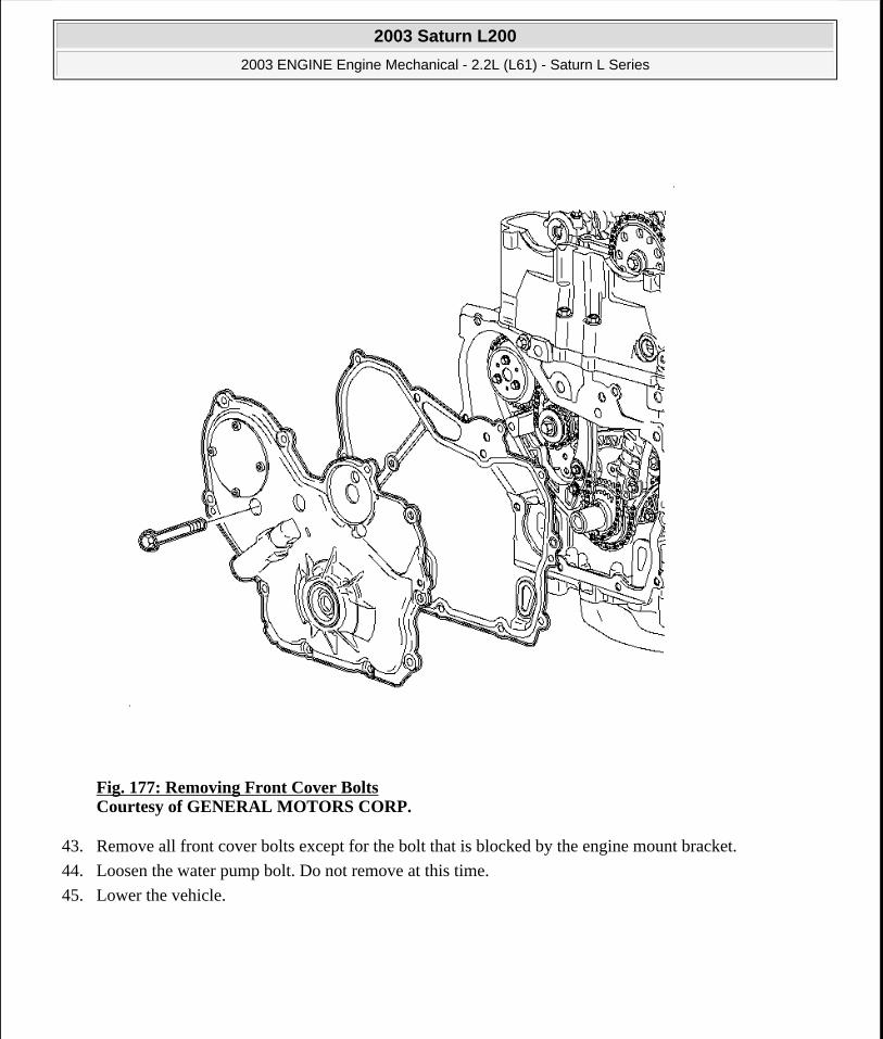
Fig. 177: Removing Front Cover Bolts Courtesy of GENERAL MOTORS CORP.
43. Remove all front cover bolts except for the bolt that is blocked by the engine mount bracket.
44. Loosen the water pump bolt. Do not remove at this time.
45. Lower the vehicle.
2003 Saturn L200
2003 ENGINE Engine Mechanical - 2.2L (L61) - Saturn L Series
steve
Monday, May 09, 2011 12:52:02 PM Page 218 © 2006 Mitchell Repair Information Company, LLC.

Fig. 178: Supporting Engine Weight With Floor Jack Courtesy of GENERAL MOTORS CORP.
46. Support the engine weight with the floor jack under the oil pan.
2003 Saturn L200
2003 ENGINE Engine Mechanical - 2.2L (L61) - Saturn L Series
steve
Monday, May 09, 2011 12:52:02 PM Page 219 © 2006 Mitchell Repair Information Company, LLC.
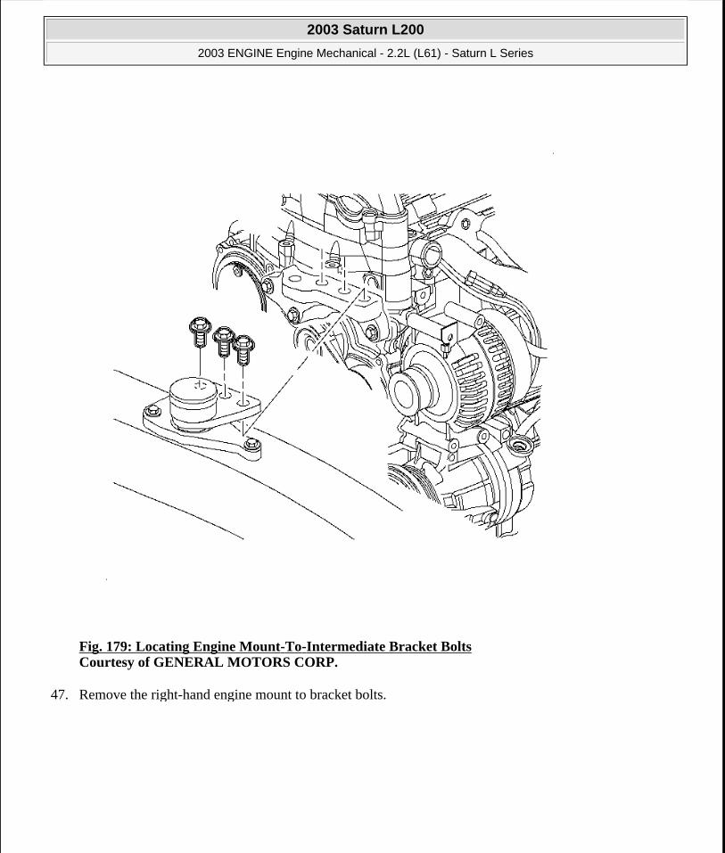
Fig. 179: Locating Engine Mount-To-Intermediate Bracket Bolts Courtesy of GENERAL MOTORS CORP.
47. Remove the right-hand engine mount to bracket bolts.
2003 Saturn L200
2003 ENGINE Engine Mechanical - 2.2L (L61) - Saturn L Series
steve
Monday, May 09, 2011 12:52:03 PM Page 220 © 2006 Mitchell Repair Information Company, LLC.

Fig. 180: Removing & Installing Engine Mount Assembly Courtesy of GENERAL MOTORS CORP.
48. Remove the engine mount to body bolts.
49. Remove the engine mount from the vehicle.
2003 Saturn L200
2003 ENGINE Engine Mechanical - 2.2L (L61) - Saturn L Series
steve
Monday, May 09, 2011 12:52:03 PM Page 221 © 2006 Mitchell Repair Information Company, LLC.

Fig. 181: Removing & Installing Engine Mount Bracket Courtesy of GENERAL MOTORS CORP.
50. Remove the engine mount bracket to engine bolts.
51. Remove the bracket from the vehicle.
2003 Saturn L200
2003 ENGINE Engine Mechanical - 2.2L (L61) - Saturn L Series
steve
Monday, May 09, 2011 12:52:03 PM Page 222 © 2006 Mitchell Repair Information Company, LLC.

Fig. 182: Removing Front Cover Courtesy of GENERAL MOTORS CORP.
52. Lower the engine.
53. Remove the crankshaft damper pulley and discard the bolt.
54. Remove the upper front cover bolt, behind the engine mount.
55. Raise the engine just enough to remove the water pump bolt.
56. Remove the front cover.
2003 Saturn L200
2003 ENGINE Engine Mechanical - 2.2L (L61) - Saturn L Series
steve
Monday, May 09, 2011 12:52:03 PM Page 223 © 2006 Mitchell Repair Information Company, LLC.

Fig. 183: Removing Adjustable Timing Chain Guide Courtesy of GENERAL MOTORS CORP.
57. Remove the adjustable timing chain guide.
2003 Saturn L200
2003 ENGINE Engine Mechanical - 2.2L (L61) - Saturn L Series
steve
Monday, May 09, 2011 12:52:03 PM Page 224 © 2006 Mitchell Repair Information Company, LLC.

Fig. 184: Fixed Timing Chain Guide & Bolts Courtesy of GENERAL MOTORS CORP.
58. Remove the fixed timing chain guide, lower bolt.
Installation Procedure
2003 Saturn L200
2003 ENGINE Engine Mechanical - 2.2L (L61) - Saturn L Series
steve
Monday, May 09, 2011 12:52:03 PM Page 225 © 2006 Mitchell Repair Information Company, LLC.

Fig. 185: Setting Mark On The Timing Chain Drive Sprocket At 5 O'clock Position Courtesy of GENERAL MOTORS CORP.
1. Set the crankshaft to 60 degrees before or after top dead center (TDC).
NOTE: Set crankshaft to 60 degrees before top-dead center or after TDC to prevent valve to piston contact.
2003 Saturn L200
2003 ENGINE Engine Mechanical - 2.2L (L61) - Saturn L Series
steve
Monday, May 09, 2011 12:52:03 PM Page 226 © 2006 Mitchell Repair Information Company, LLC.

Fig. 186: Inspecting Timing Chain Guide Courtesy of GENERAL MOTORS CORP.
2. Install the head gasket placing OBEN facing the top.
3. Install the cylinder head, aligning it on the dowels.
4. Lightly apply clean engine oil to the threads and to the bottom side of the flange of the head bolts and allow the oil to drain before installing.
IMPORTANT: Always use new cylinder head bolts.
2003 Saturn L200
2003 ENGINE Engine Mechanical - 2.2L (L61) - Saturn L Series
steve
Monday, May 09, 2011 12:52:03 PM Page 227 © 2006 Mitchell Repair Information Company, LLC.

Fig. 187: Cylinder Head Bolt Tightening Sequence Courtesy of GENERAL MOTORS CORP.
5. Install and tighten the cylinder head bolts in sequence.
Tighten: Tighten the cylinder head bolts to 30 N.m (22 lb ft) plus 155 degrees.
2003 Saturn L200
2003 ENGINE Engine Mechanical - 2.2L (L61) - Saturn L Series
steve
Monday, May 09, 2011 12:52:03 PM Page 228 © 2006 Mitchell Repair Information Company, LLC.

Fig. 188: View Of Front Cylinder Head Crankcase Bolts Courtesy of GENERAL MOTORS CORP.
6. Coat the front cylinder head bolts with LOCTITE 242®.
7. Install the front cylinder head bolts.
Tighten: Tighten the cylinder head front chain case bolts to 20 N.m (15 lb ft).
2003 Saturn L200
2003 ENGINE Engine Mechanical - 2.2L (L61) - Saturn L Series
steve
Monday, May 09, 2011 12:52:03 PM Page 229 © 2006 Mitchell Repair Information Company, LLC.
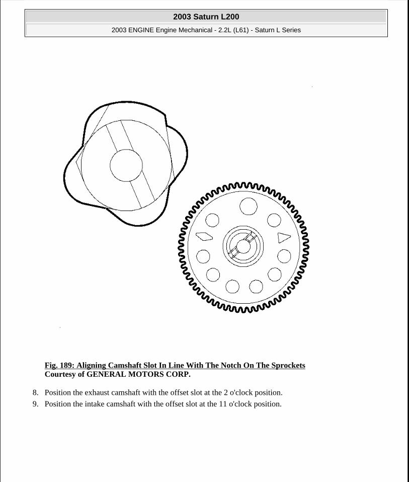
Fig. 189: Aligning Camshaft Slot In Line With The Notch On The Sprockets Courtesy of GENERAL MOTORS CORP.
8. Position the exhaust camshaft with the offset slot at the 2 o'clock position.
9. Position the intake camshaft with the offset slot at the 11 o'clock position.
2003 Saturn L200
2003 ENGINE Engine Mechanical - 2.2L (L61) - Saturn L Series
steve
Monday, May 09, 2011 12:52:03 PM Page 230 © 2006 Mitchell Repair Information Company, LLC.

Fig. 190: Positioning Intake Camshaft Courtesy of GENERAL MOTORS CORP.
10. Pull up the timing chain and install around the intake camshaft sprocket with the copper link lined up with the INT diamond timing mark.
11. Install the sprocket onto the camshaft and align with the offset slot.
12. Install the new camshaft sprocket bolt. Do not tighten.
NOTE: The camshaft sprocket bolts are not reusable, it is a torque-to-yield (TTY) bolt, and must be discarded to prevent premature failure.
2003 Saturn L200
2003 ENGINE Engine Mechanical - 2.2L (L61) - Saturn L Series
steve
Monday, May 09, 2011 12:52:03 PM Page 231 © 2006 Mitchell Repair Information Company, LLC.

Fig. 191: Setting Mark On The Timing Chain Drive Sprocket At 5 O'clock Position Courtesy of GENERAL MOTORS CORP.
13. Route the chain around the crankshaft sprockets and align the silver link to the timing mark.
IMPORTANT: There is a 2nd design adjustable guide with a contact pad for the 2nd design notched tensioner. A 2nd design guide should be used only with a 2nd design tensioner.
2003 Saturn L200
2003 ENGINE Engine Mechanical - 2.2L (L61) - Saturn L Series
steve
Monday, May 09, 2011 12:52:03 PM Page 232 © 2006 Mitchell Repair Information Company, LLC.
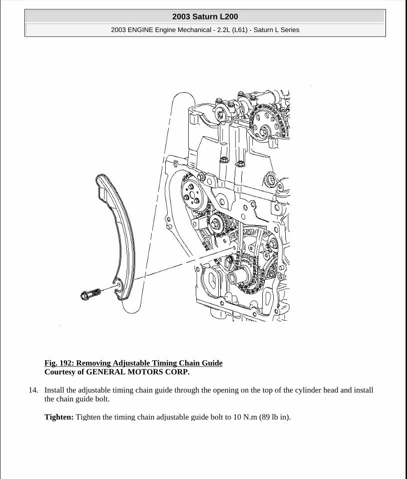
Fig. 192: Removing Adjustable Timing Chain Guide Courtesy of GENERAL MOTORS CORP.
14. Install the adjustable timing chain guide through the opening on the top of the cylinder head and install the chain guide bolt.
Tighten: Tighten the timing chain adjustable guide bolt to 10 N.m (89 lb in).
2003 Saturn L200
2003 ENGINE Engine Mechanical - 2.2L (L61) - Saturn L Series
steve
Monday, May 09, 2011 12:52:03 PM Page 233 © 2006 Mitchell Repair Information Company, LLC.

Fig. 193: Positioning Exhaust Camshaft Courtesy of GENERAL MOTORS CORP.
15. Route the timing chain around the exhaust camshaft sprocket with the silver link lined up with the offset slot.
16. Install the sprocket onto the camshaft and align with the offset slot.
17. Install the new camshaft sprocket bolt. Do not tighten.
NOTE: The camshaft sprocket bolts are not reusable, it is a torque-to-yield (TTY) bolt, and must be discarded to prevent premature failure.
2003 Saturn L200
2003 ENGINE Engine Mechanical - 2.2L (L61) - Saturn L Series
steve
Monday, May 09, 2011 12:52:03 PM Page 234 © 2006 Mitchell Repair Information Company, LLC.

Fig. 194: Using 24 mm Wrench To Support The Camshaft Courtesy of GENERAL MOTORS CORP.
18. Tighten the intake and exhaust camshaft sprocket bolts.
Tighten: Tighten the camshaft sprocket bolts to 85 N.m (63 lb ft) plus 30 degrees.
NOTE: Use a 24 mm wrench to support the camshaft while applying torque to camshaft sprocket bolt. Do not torque camshaft bolts against timing chain, as it may damage the timing chain.
IMPORTANT: Ensure that all the timing marks and colored links are aligned properly before proceeding to the next step.
2003 Saturn L200
2003 ENGINE Engine Mechanical - 2.2L (L61) - Saturn L Series
steve
Monday, May 09, 2011 12:52:03 PM Page 235 © 2006 Mitchell Repair Information Company, LLC.
Fig. 195: Fixed Timing Chain Guide & Bolts Courtesy of GENERAL MOTORS CORP.
19. Install the fixed guide and install the bolt.
Tighten: Tighten the timing chain fixed guide bolts to 10 N.m (89 lb in).
2003 Saturn L200
2003 ENGINE Engine Mechanical - 2.2L (L61) - Saturn L Series
steve
Monday, May 09, 2011 12:52:03 PM Page 236 © 2006 Mitchell Repair Information Company, LLC.

Fig. 196: Fixed Timing Chain Guide Access Plug Courtesy of GENERAL MOTORS CORP.
20. Apply LOCTITE PST565 to plug the threads.
21. Install the fixed timing chain guide bolt access hole plug.
Tighten: Tighten the timing chain guide bolt access hole plug to 40 N.m (30 lb ft).
2003 Saturn L200
2003 ENGINE Engine Mechanical - 2.2L (L61) - Saturn L Series
steve
Monday, May 09, 2011 12:52:03 PM Page 237 © 2006 Mitchell Repair Information Company, LLC.
Fig. 197: Removing Timing Chain Tensioner Courtesy of GENERAL MOTORS CORP.
22. Reset the timing chain tensioner by depressing the plunger.
23. Install the sealing ring onto the tensioner and install.
Tighten: Tighten the timing chain tensioner bolts to 75 N.m (55 lb ft).
24. Gently tap the top of the chain, between the camshaft sprockets, with your hand. This will engage the
IMPORTANT: There is a 2nd design tensioner with a notch at the plunger end of the tensioner. This tensioner should be used only with the 2nd design adjustable guide.
2003 Saturn L200
2003 ENGINE Engine Mechanical - 2.2L (L61) - Saturn L Series
steve
Monday, May 09, 2011 12:52:03 PM Page 238 © 2006 Mitchell Repair Information Company, LLC.
tensioner onto the adjustable chain guide.
Fig. 198: Removing Upper Timing Chain Guide Courtesy of GENERAL MOTORS CORP.
25. Install the upper timing chain guide and bolts.
Tighten: Tighten the timing chain upper guide bolts to 10 N.m (89 lb in).
2003 Saturn L200
2003 ENGINE Engine Mechanical - 2.2L (L61) - Saturn L Series
steve
Monday, May 09, 2011 12:52:03 PM Page 239 © 2006 Mitchell Repair Information Company, LLC.

Fig. 199: Installing Engine Front Cover Courtesy of GENERAL MOTORS CORP.
26. Install the front cover gasket and the front cover.
27. Install the front cover bolts.
Tighten: Tighten the front cover-to-block bolts to 25 N.m (18 lb ft).
IMPORTANT: Ensure that all of the timing marks and colored links are aligned properly before proceeding to the next step.
2003 Saturn L200
2003 ENGINE Engine Mechanical - 2.2L (L61) - Saturn L Series
steve
Monday, May 09, 2011 12:52:03 PM Page 240 © 2006 Mitchell Repair Information Company, LLC.

Fig. 200: Installing Water Pump Bolt Courtesy of GENERAL MOTORS CORP.
28. Install the water pump bolt.
Tighten: Tighten the water pump bolts to 25 N.m (18 lb ft).
2003 Saturn L200
2003 ENGINE Engine Mechanical - 2.2L (L61) - Saturn L Series
steve
Monday, May 09, 2011 12:52:03 PM Page 241 © 2006 Mitchell Repair Information Company, LLC.

Fig. 201: Removing & Installing Belt Tensioner Bolt Courtesy of GENERAL MOTORS CORP.
29. Install the drive belt tensioner and belt.
Tighten: Tighten the drive belt tensioner bolt to 45 N.m (33 lb ft).
2003 Saturn L200
2003 ENGINE Engine Mechanical - 2.2L (L61) - Saturn L Series
steve
Monday, May 09, 2011 12:52:03 PM Page 242 © 2006 Mitchell Repair Information Company, LLC.

Fig. 202: Removing & Installing Engine Mount Bracket Courtesy of GENERAL MOTORS CORP.
30. Install the engine mount bracket onto the engine and install the bolts.
Tighten: Tighten the engine mount bracket-to-engine bolts 90 N.m (66 lb ft).
2003 Saturn L200
2003 ENGINE Engine Mechanical - 2.2L (L61) - Saturn L Series
steve
Monday, May 09, 2011 12:52:03 PM Page 243 © 2006 Mitchell Repair Information Company, LLC.

Fig. 203: Removing & Installing Engine Mount Assembly Courtesy of GENERAL MOTORS CORP.
31. Install the engine mount assembly-to-side rail and install the fasteners.
Tighten: Tighten the engine mount-to-body bolts to 55 N.m (41 lb ft).
2003 Saturn L200
2003 ENGINE Engine Mechanical - 2.2L (L61) - Saturn L Series
steve
Monday, May 09, 2011 12:52:03 PM Page 244 © 2006 Mitchell Repair Information Company, LLC.
Fig. 204: Locating Engine Mount-To-Intermediate Bracket Bolts Courtesy of GENERAL MOTORS CORP.
32. Lower the engine and align the engine mount bolts.
33. Install the engine mount bolts-to-bracket bolts.
Tighten: Tighten the engine mount-to-engine mount bracket bolts to 55 N.m (41 lb ft).
34. Remove the floor jack.
2003 Saturn L200
2003 ENGINE Engine Mechanical - 2.2L (L61) - Saturn L Series
steve
Monday, May 09, 2011 12:52:03 PM Page 245 © 2006 Mitchell Repair Information Company, LLC.

Fig. 205: Removing & Installing Damper Assembly Courtesy of GENERAL MOTORS CORP.
35. Raise the vehicle.
36. Install the crankshaft damper.
37. Lubricate the front oil seal and the seal surface of the crankshaft balancer with an engine oil supplement.
38. Install the damper onto the crankshaft indexing keyway. Use care to properly align the keyway and flats on the damper with the oil pump drive.
NOTE: Misalignment of the keyway may cause damage to the oil pump.
2003 Saturn L200
2003 ENGINE Engine Mechanical - 2.2L (L61) - Saturn L Series
steve
Monday, May 09, 2011 12:52:03 PM Page 246 © 2006 Mitchell Repair Information Company, LLC.

Fig. 206: Removing & Installing Harmonic Balancer Using Holder On Damper Assembly Courtesy of GENERAL MOTORS CORP.
39. Install the new crankshaft damper pulley bolt.
Tighten: Tighten the crankshaft damper pulley bolt to 100 N.m (74 lb ft) plus 75 degrees.
IMPORTANT: It may be necessary to lower the engine slightly with a crow bar so that the bolt-head clears the frame rail.
2003 Saturn L200
2003 ENGINE Engine Mechanical - 2.2L (L61) - Saturn L Series
steve
Monday, May 09, 2011 12:52:03 PM Page 247 © 2006 Mitchell Repair Information Company, LLC.
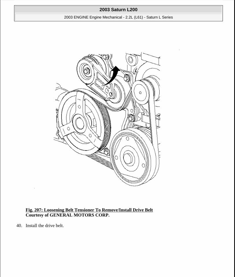
Fig. 207: Loosening Belt Tensioner To Remove/Install Drive Belt Courtesy of GENERAL MOTORS CORP.
40. Install the drive belt.
2003 Saturn L200
2003 ENGINE Engine Mechanical - 2.2L (L61) - Saturn L Series
steve
Monday, May 09, 2011 12:52:03 PM Page 248 © 2006 Mitchell Repair Information Company, LLC.

Fig. 208: Removing/Installing Right Front Lower Splash Shield Courtesy of GENERAL MOTORS CORP.
41. Install the A/C line clamps.
42. Install the right wheel splash shield.
2003 Saturn L200
2003 ENGINE Engine Mechanical - 2.2L (L61) - Saturn L Series
steve
Monday, May 09, 2011 12:52:03 PM Page 249 © 2006 Mitchell Repair Information Company, LLC.

Fig. 209: Removing & Installing Tire & Wheel Assembly Courtesy of GENERAL MOTORS CORP.
43. Install the tire/wheel.
1. Hand tighten all 5 wheel bolts.
2. Use a torque wrench to initial tighten wheel bolts using a crisscross pattern.
Tighten: Tighten the wheel bolts (initial torque) to 63 N.m (46 lb ft).
3. Use a torque wrench to final tighten wheel bolts using a crisscross pattern.
Tighten: Tighten the wheel bolts (final torque) to 125 N.m (92 lb ft).
2003 Saturn L200
2003 ENGINE Engine Mechanical - 2.2L (L61) - Saturn L Series
steve
Monday, May 09, 2011 12:52:03 PM Page 250 © 2006 Mitchell Repair Information Company, LLC.

44. Install the wheel cover.
Fig. 210: Removing & Installing Camshaft Cover Assembly Courtesy of GENERAL MOTORS CORP.
45. Lower the vehicle.
46. Install the camshaft cover. Ensure that the camshaft cover seals are properly seated in the cover.
47. Install the cover bolts and ground strap nut.
Tighten: Tighten the camshaft cover bolts to 10 N.m (89 lb in).
2003 Saturn L200
2003 ENGINE Engine Mechanical - 2.2L (L61) - Saturn L Series
steve
Monday, May 09, 2011 12:52:03 PM Page 251 © 2006 Mitchell Repair Information Company, LLC.
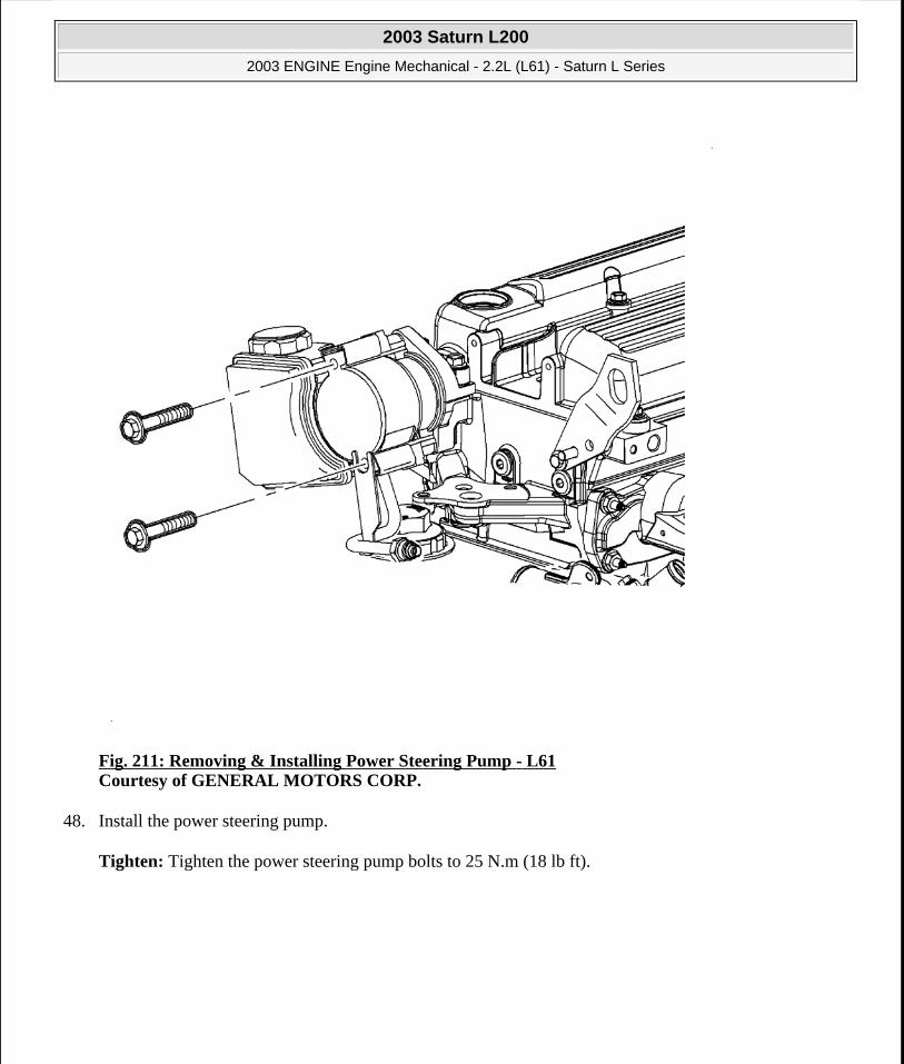
Fig. 211: Removing & Installing Power Steering Pump - L61 Courtesy of GENERAL MOTORS CORP.
48. Install the power steering pump.
Tighten: Tighten the power steering pump bolts to 25 N.m (18 lb ft).
2003 Saturn L200
2003 ENGINE Engine Mechanical - 2.2L (L61) - Saturn L Series
steve
Monday, May 09, 2011 12:52:03 PM Page 252 © 2006 Mitchell Repair Information Company, LLC.

Fig. 212: Installing Spark Plugs Courtesy of GENERAL MOTORS CORP.
49. Install the spark plugs.
Tighten: Tighten the spark plugs to 20 N.m (15 lb ft).
2003 Saturn L200
2003 ENGINE Engine Mechanical - 2.2L (L61) - Saturn L Series
steve
Monday, May 09, 2011 12:52:03 PM Page 253 © 2006 Mitchell Repair Information Company, LLC.

Fig. 213: Installing Ignition Module Assembly Courtesy of GENERAL MOTORS CORP.
50. Install the ignition coil and module assembly to the camshaft cover.
Tighten: Tighten the ignition coil-to-camshaft cover bolts to 8 N.m (71 lb in).
2003 Saturn L200
2003 ENGINE Engine Mechanical - 2.2L (L61) - Saturn L Series
steve
Monday, May 09, 2011 12:52:03 PM Page 254 © 2006 Mitchell Repair Information Company, LLC.

Fig. 214: Installing Intake Manifold Courtesy of GENERAL MOTORS CORP.
51. Install the intake manifold onto the intake manifold. The gasket may be reused if not damaged.
52. Install the intake manifold.
53. Install the intake manifold bolts and nuts. Tighten by starting from the center bolt and working outward.
Tighten:
Tighten the intake manifold-to-cylinder head bolts to 10 N.m (89 lb in).
Tighten the manifold-to-cylinder head nuts to 10 N.m (89 lb in).
2003 Saturn L200
2003 ENGINE Engine Mechanical - 2.2L (L61) - Saturn L Series
steve
Monday, May 09, 2011 12:52:03 PM Page 255 © 2006 Mitchell Repair Information Company, LLC.

Fig. 215: Removing & Installing Oil Level Indicator & Tube Courtesy of GENERAL MOTORS CORP.
54. Attach the wiring harness to the brackets located under the intake manifold.
55. Install the oil indicator tube assembly.
Tighten: Tighten the oil level indicator tube-to-intake manifold bolt to 10 N.m (89 lb in).
2003 Saturn L200
2003 ENGINE Engine Mechanical - 2.2L (L61) - Saturn L Series
steve
Monday, May 09, 2011 12:52:03 PM Page 256 © 2006 Mitchell Repair Information Company, LLC.

Fig. 216: Removing & Installing Throttle Body Assembly Courtesy of GENERAL MOTORS CORP.
56. Install the throttle body. The gasket may be reused if not damaged.
57. Install the throttle body mounting bolts and nuts. Install the throttle cable.
Tighten:
Tighten the throttle body bolts to 10 N.m (89 lb in).
Tighten the throttle body nuts to 10 N.m (89 lb in).
58. Position the engine harness and install the fasteners.
Tighten: Tighten the engine harness bracket bolts to 10 N.m (89 lb in).
59. Connect the electrical connections.
2003 Saturn L200
2003 ENGINE Engine Mechanical - 2.2L (L61) - Saturn L Series
steve
Monday, May 09, 2011 12:52:03 PM Page 257 © 2006 Mitchell Repair Information Company, LLC.

60. Install the camshaft cover ground strap.
Tighten: Tighten the camshaft cover ground strap fastener to 10 N.m (89 lb in).
Fig. 217: Removing & Installing Surge Tank Coolant Air Bleed Hose Courtesy of GENERAL MOTORS CORP.
61. Attach the cylinder head degas hose onto the coolant reservoir and attach to the harness retainers.
Tighten: Tighten the degas hose bracket bolts to 10 N.m (89 lb in).
62. Attach the hoses.
1. Upper radiator hose
2003 Saturn L200
2003 ENGINE Engine Mechanical - 2.2L (L61) - Saturn L Series
steve
Monday, May 09, 2011 12:52:03 PM Page 258 © 2006 Mitchell Repair Information Company, LLC.
2. Crankcase ventilation hose
3. Fuel pressure regulator hose
4. Brake booster hose
5. EVAP purge hose
63. Install the fuel lines. Ensure that the lines are routed correctly.
64. Clip the lines into place and install the fuel line bracket and bolt.
Tighten: Tighten the fuel line bolt to 10 N.m (89 lb in).
NOTE: Replace plastic fuel retainer whenever the fuel supply is disconnected at the fuel rail. Install the new retainer into the female cavity of the connection. Care must be taken to assure that the locking tab is centered in the window of the female cavity. Firmly press the female connection onto the male end until a click is heard, then pull back to confirm engagement. Pinched, kinked, or damaged fuel lines must be replaced.
2003 Saturn L200
2003 ENGINE Engine Mechanical - 2.2L (L61) - Saturn L Series
steve
Monday, May 09, 2011 12:52:03 PM Page 259 © 2006 Mitchell Repair Information Company, LLC.

Fig. 218: Removing Exhaust Manifold Pipe Courtesy of GENERAL MOTORS CORP.
65. Install the exhaust flange onto the exhaust flange.
66. Raise the vehicle. Refer to Lifting and Jacking the Vehicle in General Information.
67. Position the manifold down pipe onto the flange studs.
68. Install the flange nuts.
Tighten: Tighten the exhaust manifold pipe-to-exhaust manifold nuts to 30 N.m (22 lb ft).
2003 Saturn L200
2003 ENGINE Engine Mechanical - 2.2L (L61) - Saturn L Series
steve
Monday, May 09, 2011 12:52:03 PM Page 260 © 2006 Mitchell Repair Information Company, LLC.

Fig. 219: Removing & Installing Exhaust Manifold Pipe-To-Exhaust/Resonator Fasteners Courtesy of GENERAL MOTORS CORP.
69. Install the exhaust down pipe to the resonator bolts.
Tighten: Tighten the exhaust manifold pipe-to-resonator bolts to 20 N.m (15 lb ft).
70. Drain the oil.
Tighten: Tighten the oil drain plug to 25 N.m (18 lb ft).
2003 Saturn L200
2003 ENGINE Engine Mechanical - 2.2L (L61) - Saturn L Series
steve
Monday, May 09, 2011 12:52:03 PM Page 261 © 2006 Mitchell Repair Information Company, LLC.

Fig. 220: Removing & Installing Exhaust Manifold Heat Shield Courtesy of GENERAL MOTORS CORP.
71. Lower the vehicle.
72. Install the exhaust manifold heat shield and install the bolts.
Tighten: Tighten the exhaust manifold heat shield bolts to 25 N.m (18 lb ft).
2003 Saturn L200
2003 ENGINE Engine Mechanical - 2.2L (L61) - Saturn L Series
steve
Monday, May 09, 2011 12:52:03 PM Page 262 © 2006 Mitchell Repair Information Company, LLC.

Fig. 221: Removing & Installing Air Cleaner Assembly Courtesy of GENERAL MOTORS CORP.
73. Install the air cleaner and inlet tube assembly.
2003 Saturn L200
2003 ENGINE Engine Mechanical - 2.2L (L61) - Saturn L Series
steve
Monday, May 09, 2011 12:52:03 PM Page 263 © 2006 Mitchell Repair Information Company, LLC.

Fig. 222: View of Oil Cap Courtesy of GENERAL MOTORS CORP.
74. Add engine oil.
75. Check the level and install the oil cap.
2003 Saturn L200
2003 ENGINE Engine Mechanical - 2.2L (L61) - Saturn L Series
steve
Monday, May 09, 2011 12:52:03 PM Page 264 © 2006 Mitchell Repair Information Company, LLC.

Fig. 223: Removing Surge Tank Cap Courtesy of GENERAL MOTORS CORP.
76. Fill the coolant tank.
1. Add 50/50 DEX-COOL® and water.
Specifications:
The auto trans volume equals 6.9 quarts.
The manual trans volume equals 7 quarts.
2. Install the coolant surge cap.
77. Connect the battery cable.
2003 Saturn L200
2003 ENGINE Engine Mechanical - 2.2L (L61) - Saturn L Series
steve
Monday, May 09, 2011 12:52:03 PM Page 265 © 2006 Mitchell Repair Information Company, LLC.
78. Start the vehicle and inspect for leaks.
ENGINE FLYWHEEL REPLACEMENT
Removal Procedure
1. Remove the transmission. Refer to Transmission Replacement in Automatic Transaxle - 4T40-E/4T45-E.
NOTE: After cylinder block, head, or lifter replacement, it will be necessary to allow the engine to idle for 3-5 minutes. If the lifters are noisy, warm the engine up at less than 200 RPM. After the coolant temperature has reached approximately 85°C (185°F), cycle the engine RPM from idle to 300 RPM for approximately 10 minutes or drive the vehicle 8 kilometers (5 miles) to purge the air. If the air cannot be purged, the faulty lifters will have to be replaced.
2003 Saturn L200
2003 ENGINE Engine Mechanical - 2.2L (L61) - Saturn L Series
steve
Monday, May 09, 2011 12:52:03 PM Page 266 © 2006 Mitchell Repair Information Company, LLC.

Fig. 224: View Of Flywheel Courtesy of GENERAL MOTORS CORP.
2. Remove the flywheel bolts, and note the position of the flywheel to the crankshaft.
3. Remove the flywheel.
Installation Procedure
2003 Saturn L200
2003 ENGINE Engine Mechanical - 2.2L (L61) - Saturn L Series
steve
Monday, May 09, 2011 12:52:03 PM Page 267 © 2006 Mitchell Repair Information Company, LLC.

Fig. 225: View Of Flywheel Courtesy of GENERAL MOTORS CORP.
1. Position the flywheel on the crankshaft as previously noted.
2. Install the flywheel bolts.
Tighten: Tighten the flywheel bolts to 53 N.m (39 lb ft) plus 25 degrees.
3. Install the transmission. Refer to Transmission Replacement in Automatic Transaxle - 4T40-E/4T45-E.
ENGINE REPLACEMENT (MANUAL TRANSMISSION)
NOTE: Refer to FASTENER NOTICE in Cautions and Notices.
2003 Saturn L200
2003 ENGINE Engine Mechanical - 2.2L (L61) - Saturn L Series
steve
Monday, May 09, 2011 12:52:03 PM Page 268 © 2006 Mitchell Repair Information Company, LLC.

Tools Required
J 43628 Frame Alignment Fixture
J 44015 Steering Linkage Installer
Removal Procedure
1. Remove the steering gear-to-intermediate shaft pinch bolt. Access is from the inside of the vehicle at the front of the dash.
2. Remove the battery.
3. Disconnect the main wire feed to the fuse block.
4. Disconnect the main ground on the left fender well.
5. Remove the intake air temperature (IAT) electrical connector.
6. Remove the air cleaner lid and the inlet duct.
7. Remove the air box.
8. Disconnect the purge hose from the throttle body and route away from the engine.
9. Disconnect the following electrical connections:
1. The purge solenoid
2. The rear HO2S sensor
3. The main harness connector by the master cylinder
4. The transaxle back-up switch
10. Remove the front-of-dash cover.
11. Remove the PCM boot from the front of the dash.
12. Disconnect the PCM electrical connectors and secure to the engine.
13. Remove the fuse block.
14. Disconnect the engine harness main connector from the bottom of the fuse block.
15. Remove the battery tray and the fuse block tray.
16. Remove the cruise control and throttle cables.
17. Disconnect the brake assist vacuum line from the throttle body and route away from the engine.
18. Loosen the pinch bolt securing the control assembly rod to the control shaft lever assembly.
19. Remove the pin retaining control shaft lever to shift control shaft of the transaxle.
20. Remove the retaining clips holding the control shaft lever assembly to the transaxle and frame assembly brackets.
21. Remove the control shaft lever assembly by pulling straight up from the pivot pins.
22. Drain the coolant.
NOTE: The control shaft lever retaining pin has a spring loaded locking feature securing the pin in place. If this spring is not depressed before attempting to remove the pin, damage to the pin will result.
2003 Saturn L200
2003 ENGINE Engine Mechanical - 2.2L (L61) - Saturn L Series
steve
Monday, May 09, 2011 12:52:03 PM Page 269 © 2006 Mitchell Repair Information Company, LLC.

23. Remove the heater hoses from the front of the dash.
24. Remove the upper and lower radiator hoses from the radiator.
25. Relieve the fuel pressure.
26. Disconnect the fuel lines.
27. Secure the radiator to the upper radiator support.
28. Raise the vehicle on a hoist.
29. Remove both of the front wheels.
30. Remove the right front splash shield.
31. Remove the left front wheel liner push pin from the frame.
32. Install wood blocks between the transaxle case and frame.
33. Install wood blocks between the crank pulley and frame.
34. Lower the vehicle.
35. Disconnect the right engine and left transaxle mounts by removing the mount assembly-to-engine/transaxle bolts. The mount brackets will remain on the engine and transaxle.
36. Disconnect the rear oxygen sensor harness from the frame at the 2 attachment points.
37. Remove the exhaust manifold pipe from the catalytic converter forward.
38. Remove the A/C line to frame attachment clip at the front of the frame.
39. Remove the A/C compressor from the engine and secure to the cooling module.
40. Remove the tie rod-to-steering knuckle bolts and separate the tie rod from the steering knuckle assembly. Discard the tie rod bolts.
41. Remove the stabilizer bar links from the strut assembly.
42. Remove the lower ball stud bolt and separate the ball from the steering knuckle assembly.
43. Remove the suspension support assemblies.
44. Remove the suspension support cage nuts from the body. Discard the cage nuts.
45. Support the powertrain and frame with the powertrain lifting table and the J 43628 .
46. Remove the remaining 4 frame-to-body attachment fasteners.
47. Carefully lower the powertrain and frame assembly from the vehicle.
CAUTION: Ensure that the vehicle is properly supported and squarely positioned. To help avoid personal injury when a vehicle is on a hoist, provide additional support for the vehicle on the opposite end from which the components are being removed.
IMPORTANT: It is not necessary to disconnect the A/C lines.
NOTE: Do not attempt to separate the joint using a wedge-type tool because seal may be damaged.
2003 Saturn L200
2003 ENGINE Engine Mechanical - 2.2L (L61) - Saturn L Series
steve
Monday, May 09, 2011 12:52:03 PM Page 270 © 2006 Mitchell Repair Information Company, LLC.

48. Remove the remaining 4 cage nuts and discard.
Installation Procedure
Fig. 226: Identifying Engine Frame Alignment Fixture Courtesy of GENERAL MOTORS CORP.
1. Install the new cage nuts into the body as torque retention of the old nuts may not be sufficient.
2. Carefully raise the powertrain into the vehicle.
3. Install the 4 new frame-to-body bolts.
4. Install the suspension supports using the new bolt and tighten all of the frame bolts.
Tighten: Tighten the suspension support bolts to 100 N.m (74 lb ft).
5. Install the ball stud into the steering knuckle. Use the new ball stud nut.
Tighten: Tighten the ball stud-to-steering knuckle nuts to 100 N.m (74 lb ft).
IMPORTANT: Ensure that the J 43628 fully engages into all alignment holes.
IMPORTANT: Do not tighten the fasteners at this time.
2003 Saturn L200
2003 ENGINE Engine Mechanical - 2.2L (L61) - Saturn L Series
steve
Monday, May 09, 2011 12:52:03 PM Page 271 © 2006 Mitchell Repair Information Company, LLC.

6. Install the stabilizer link-to-strut assembly.
Tighten: Tighten the stabilizer link-to-strut assembly to 65 N.m (50 lb ft).
7. Install the tie rod into the steering knuckle.
8. Using the J 44015 , or equivalent, seat the tie rod end into the knuckle and tighten again.
Tighten: Tighten the tie rod end linkage installer to 45 N.m (35 lb ft).
9. Remove the linkage installer and install the new tie rod nut and tighten.
Tighten: Tighten the tie rod nut to 60 N.m (45 lb ft).
10. Install the exhaust manifold pipe.
11. Install the A/C compressor-to-engine mounting bolts.
Tighten: Tighten the A/C compressor-to-block bolt to 25 N.m (18 lb ft).
12. Install the A/C line-to-frame attachment clip at the front of the frame.
13. Route the rear oxygen sensor harness and attach to the attachment points.
14. Install the right engine mount bolts and install the left transaxle mount bolts.
Tighten:
Tighten the engine mount-to-engine mount bracket bolts to 55 N.m (41 lb ft).
Tighten the transaxle mount bolts to 55 N.m (41 lb ft).
15. Raise the vehicle.
16. Remove the wood blocks from the crank pulley and transaxle case.
17. Install the left front wheel liner push pin from the frame.
18. Install the right front splash shield.
19. Install both of the front wheels.
20. Lower the vehicle.
21. Remove the radiator from the upper radiator support.
22. Connect the fuel lines. Use new fuel line retainer clips.
IMPORTANT: Use a new tie rod nut. The torque retention of the old nut may not be sufficient.
CAUTION: Ensure that the vehicle is properly supported and squarely positioned. To help avoid personal injury when a vehicle is on a hoist, provide additional support for the vehicle on the opposite end from which the components are being removed.
2003 Saturn L200
2003 ENGINE Engine Mechanical - 2.2L (L61) - Saturn L Series
steve
Monday, May 09, 2011 12:52:03 PM Page 272 © 2006 Mitchell Repair Information Company, LLC.

23. Install the upper and lower radiator hoses from the radiator.
24. Install the heater hose.
25. Connect the brake assist vacuum lines to the brake booster.
26. Install and adjust the shift control rod as follows:
1. Install the shift rod into the shift linkage assembly.
2. Rotate the transaxle shift control shaft clockwise, toward the passenger side of the vehicle, and depress the spring loaded transaxle shift linkage lock pin on the transaxle case.
3. Pull up the shift lever boot.
4. Move the shift lever to 5th (reverse gate) using a 3/8 in. punch to hold in place.
5. Tighten the pinch bolt.
Tighten: Tighten the shift control rod pinch bolt to 12 N.m (9 lb ft) plus 180 degrees.
27. Attach the cruise control and throttle cables.
28. Install the battery tray and fuse block tray.
29. Connect the engine harness main connector on the bottom of the fuse block.
30. Install the fuse block.
31. Connect the PCM electrical connectors.
32. Install the PCM boot under the front-of-dash cover.
33. Install the front-of-dash cover.
34. Connect the following connections:
The purge solenoid
The rear oxygen sensor
The main harness connector by the master cylinder
The transaxle back-up switch
35. Connect the purge hose to the throttle body.
36. Install the air cleaner box.
37. Install the air cleaner lid and the inlet duct.
38. Connect the intake air temperature (IAT) electrical connection.
39. Connect the main ground on the left fender well.
40. Connect the main wire feed to the fuse block.
41. Install the battery.
42. Connect the steering gear-to-intermediate shaft pinch bolt and tighten.
Tighten: Tighten the steering gear-to-intermediate shaft pinch bolt to 30 N.m (22 lb ft).
43. Refill the coolant tank.
44. Add power steering fluid.
2003 Saturn L200
2003 ENGINE Engine Mechanical - 2.2L (L61) - Saturn L Series
steve
Monday, May 09, 2011 12:52:03 PM Page 273 © 2006 Mitchell Repair Information Company, LLC.

ENGINE REPLACEMENT (AUTOMATIC TRANSMISSION)
Removal Procedure
Fig. 227: Removing & Installing Engine - Automatic Transmission Courtesy of GENERAL MOTORS CORP.
1. Remove the battery.
2. Disconnect the main wire feed to the fuse block.
3. Disconnect the main ground on the left fender well.
4. Remove the intake air temperature (IAT) electrical connection.
5. Remove the air cleaner lid and the inlet duct.
6. Remove the air box.
7. Disconnect the purge hose from the throttle body and route away from the engine.
2003 Saturn L200
2003 ENGINE Engine Mechanical - 2.2L (L61) - Saturn L Series
steve
Monday, May 09, 2011 12:52:03 PM Page 274 © 2006 Mitchell Repair Information Company, LLC.

8. Disconnect the following electrical connections:
The purge solenoid electrical
The rear HO2S sensor
The main harness connector near the master cylinder
The generator
The A/C pressure switch
The transmission (3 connectors)
The right front speed sensor (disconnect and pull through the fender well)
9. Remove the cowl cover.
10. Remove the PCM boot from the cowl.
11. Disconnect the PCM electrical connectors and secure to the engine.
12. Remove the fuse block lid.
13. Disconnect the engine harness connectors from the fuse block.
14. Remove the battery tray and fuse block tray.
15. Disconnect the cruise control and throttle cables.
16. Remove the coolant reservoir cap.
17. Disconnect the brake assist vacuum line from the throttle body and route away from the engine.
18. Relieve the fuel pressure.
19. Disconnect the fuel lines and secure away from the engine.
20. Disconnect the EVAP purge hose at the EVAP purge solenoid.
21. Raise the vehicle.
22. Drain the engine coolant.
23. Remove the starter.
24. Remove the torque converter bolts.
25. Remove the exhaust system from the catalytic converter forward.
26. Disconnect the transmission nose bracket.
27. Remove the A/C compressor mounting bolts and secure to the frame rail.
28. Disconnect the lower engine to transmission bell housing bolts. Do not remove the upper bolts at this time.
29. Lower the vehicle.
CAUTION: Ensure that the vehicle is properly supported and squarely positioned. To help avoid personal injury when a vehicle is on a hoist, provide additional support for the vehicle on the opposite end from which the components are being removed.
IMPORTANT: It is not necessary to disconnect the A/C lines.
2003 Saturn L200
2003 ENGINE Engine Mechanical - 2.2L (L61) - Saturn L Series
steve
Monday, May 09, 2011 12:52:03 PM Page 275 © 2006 Mitchell Repair Information Company, LLC.

30. Disconnect the heater hoses at the lower cowl.
31. Remove the main hose to the coolant reservoir from the engine inlet adapter.
32. Remove the lower radiator hose from the engine.
33. Remove the upper radiator hose from the engine.
34. Drain the power steering fluid by removing the smaller hose from under the reservoir.
35. Disconnect the metal power steering line.
36. Attach the engine lift hoist to the lift hooks on the engine and support the engine weight.
37. Support the weight of the transaxle with the floor jack or jack stand.
38. Remove the right front engine mount from the wheel housing.
39. Remove the engine mount bracket from the engine.
40. Remove the upper bell housing bolts.
41. Lift the engine out of the vehicle.
Installation Procedure
2003 Saturn L200
2003 ENGINE Engine Mechanical - 2.2L (L61) - Saturn L Series
steve
Monday, May 09, 2011 12:52:03 PM Page 276 © 2006 Mitchell Repair Information Company, LLC.

Fig. 228: Removing & Installing Engine - Automatic Transmission Courtesy of GENERAL MOTORS CORP.
1. Support the transaxle with the floor jack or jack stand.
2. Lower the engine into the vehicle and guide to mate with the dowel pins on the transmission.
3. When the engine and transmission are aligned on the shuffle pins, install the upper bell housing bolts. Do not torque at this time.
4. Install the engine mount bracket onto the engine and install the bolts.
Tighten: Tighten the engine mount bracket-to-engine bolts to 90 N.m (66 lb ft).
5. Install the right front engine mount and install the bolts.
NOTE: Refer FASTENER NOTICE in Cautions and Notices.
2003 Saturn L200
2003 ENGINE Engine Mechanical - 2.2L (L61) - Saturn L Series
steve
Monday, May 09, 2011 12:52:03 PM Page 277 © 2006 Mitchell Repair Information Company, LLC.

Tighten: Tighten the engine mount-to-body bolts to 55 N.m (41 lb ft).
6. Install the transmission nose bracket bolts.
Tighten: Tighten the transmission nose bracket bolts to 35 N.m (26 lb ft).
7. Remove the engine lift hoist.
8. Attach the metal power steering line.
9. Attach the lower power steering hose to the bottom of the power steering reservoir.
10. Install the upper radiator hose.
11. Install the lower radiator hose.
12. Attach the main coolant reservoir hose to the engine.
13. Raise the vehicle.
14. Install the lower engine to transmission bell housing bolts and tighten.
Tighten: Tighten the lower engine-to-transmission bell housing bolts to 65 N.m (48 lb ft).
15. Install the torque convertor bolts.
Tighten: Tighten the torque convertor bolts to 45 N.m (33 lb ft).
16. Install the starter.
17. Connect the heater hoses at the lower cowl.
18. Install the A/C compressor to engine mounting bolts.
Tighten: Tighten the A/C compressor-to-block bolts to 25 N.m (18 lb ft).
19. Install the accessory drive belt.
20. Install the exhaust down pipes to the catalytic convertor.
21. Lower the vehicle.
22. Tighten the upper bell housing bolts.
Tighten: Tighten the upper bell housing bolts to 65 N.m (48 lb ft).
23. Connect the EVAP purge solenoid and EVAP purge hose.
24. Connect the fuel lines.
25. Connect the brake assist vacuum hose.
CAUTION: Ensure that the vehicle is properly supported and squarely positioned. To help avoid personal injury when a vehicle is on a hoist, provide additional support for the vehicle on the opposite end from which the components are being removed.
2003 Saturn L200
2003 ENGINE Engine Mechanical - 2.2L (L61) - Saturn L Series
steve
Monday, May 09, 2011 12:52:04 PM Page 278 © 2006 Mitchell Repair Information Company, LLC.

26. Install the cruise control and throttle cables.
27. Install the battery tray and fuse block tray.
28. Install the fuse block.
1. Install the fuse block mounting bolts.
2. Route the engine harness into the fuse block.
3. Connect the lower weather pack connector.
4. Connect the main engine harness under the fuse block panel.
5. Assemble the fuse block and install the fuse block cover.
29. Connect the PCM electrical connector.
30. Install the PCM boot to the cowl.
31. Install the cowl cover.
32. Connect the following electrical connections:
1. The main harness connector by the master cylinder
2. The rear HO2S sensor
3. The purge solenoid electrical
33. Connect the purge hose to the throttle body.
34. Install the air box.
35. Install the air cleaner lid and the inlet duct.
36. Install the intake air temperature (IAT) electrical connection.
37. Connect the main ground on the left fender wall.
38. Connect the main wire feed to the fuse block.
39. Install the battery.
40. Add coolant.
41. Add power steering fluid.
42. Start the engine and check for leaks.
ENGINE OIL AND OIL FILTER REPLACEMENT
Removal Procedure
2003 Saturn L200
2003 ENGINE Engine Mechanical - 2.2L (L61) - Saturn L Series
steve
Monday, May 09, 2011 12:52:04 PM Page 279 © 2006 Mitchell Repair Information Company, LLC.

Fig. 229: View of Oil Cap Courtesy of GENERAL MOTORS CORP.
NOTE: Do not use a universal type oil filter wrench to remove oil filter cap. Damage to the oil cap and the engine may result.
NOTE: The cylinder block sealing surface can be damaged if the oil filter cap is removed using a chisel or screwdriver.
IMPORTANT: Either a 68 mm (2.68 in) (14 Flute Oil Filter Wrench) or a 32 mm (.26 in) socket must be used to loosen the oil filter cap assembly.
2003 Saturn L200
2003 ENGINE Engine Mechanical - 2.2L (L61) - Saturn L Series
steve
Monday, May 09, 2011 12:52:04 PM Page 280 © 2006 Mitchell Repair Information Company, LLC.

1. Remove the engine oil filler cap.
Fig. 230: View Of Engine & Oil Filter Courtesy of GENERAL MOTORS CORP.
2. Using a 14-flat 68 mm (2.68 in) oil filter wrench or 32 mm (1.26 in) socket, fully unscrew the oil filter housing cap to allow the drain back of the oil contained in the housing.
IMPORTANT: Make sure the oil filter gasket is removed from the cylinder block. Do not tighten the oil filter.
2003 Saturn L200
2003 ENGINE Engine Mechanical - 2.2L (L61) - Saturn L Series
steve
Monday, May 09, 2011 12:52:04 PM Page 281 © 2006 Mitchell Repair Information Company, LLC.

Fig. 231: Removing/Installing Oil Pan Drain Plug Courtesy of GENERAL MOTORS CORP.
3. Remove the engine oil drain plug and drain the oil into an approved container.
2003 Saturn L200
2003 ENGINE Engine Mechanical - 2.2L (L61) - Saturn L Series
steve
Monday, May 09, 2011 12:52:04 PM Page 282 © 2006 Mitchell Repair Information Company, LLC.
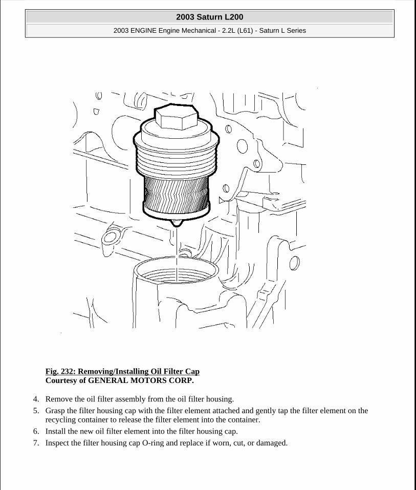
Fig. 232: Removing/Installing Oil Filter Cap Courtesy of GENERAL MOTORS CORP.
4. Remove the oil filter assembly from the oil filter housing.
5. Grasp the filter housing cap with the filter element attached and gently tap the filter element on the recycling container to release the filter element into the container.
6. Install the new oil filter element into the filter housing cap.
7. Inspect the filter housing cap O-ring and replace if worn, cut, or damaged.
2003 Saturn L200
2003 ENGINE Engine Mechanical - 2.2L (L61) - Saturn L Series
steve
Monday, May 09, 2011 12:52:04 PM Page 283 © 2006 Mitchell Repair Information Company, LLC.

Fig. 233: View Of Engine & Oil Filter Courtesy of GENERAL MOTORS CORP.
8. Using a 14-flat 68 mm (2.68 in) oil filter wrench or 32 mm (1.26 in) socket, install the oil filter assembly into the oil filter housing.
Tighten: Tighten the oil filter cap to 25 N.m (18 lb ft).
2003 Saturn L200
2003 ENGINE Engine Mechanical - 2.2L (L61) - Saturn L Series
steve
Monday, May 09, 2011 12:52:04 PM Page 284 © 2006 Mitchell Repair Information Company, LLC.
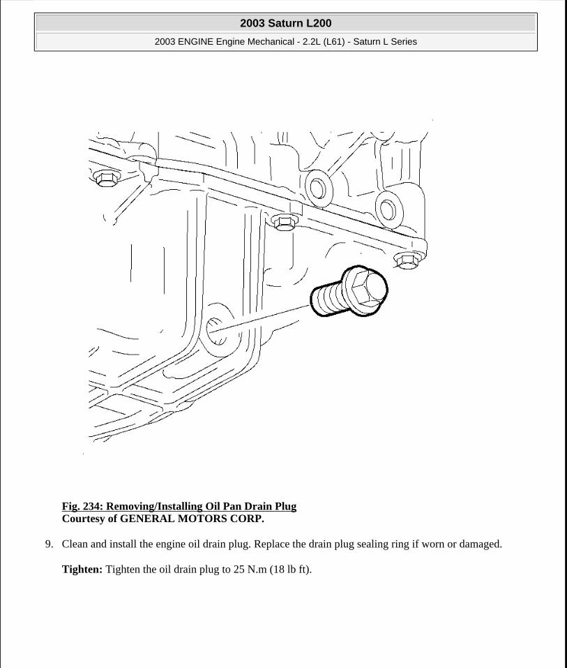
Fig. 234: Removing/Installing Oil Pan Drain Plug Courtesy of GENERAL MOTORS CORP.
9. Clean and install the engine oil drain plug. Replace the drain plug sealing ring if worn or damaged.
Tighten: Tighten the oil drain plug to 25 N.m (18 lb ft).
2003 Saturn L200
2003 ENGINE Engine Mechanical - 2.2L (L61) - Saturn L Series
steve
Monday, May 09, 2011 12:52:04 PM Page 285 © 2006 Mitchell Repair Information Company, LLC.

Fig. 235: View of Engine Oil Cap Courtesy of GENERAL MOTORS CORP.
10. Fill the engine with 4.73 L (5 quarts) of new 5W-30 engine oil.
11. Install the engine oil filler cap.
12. Start the engine and check for leaks.
2003 Saturn L200
2003 ENGINE Engine Mechanical - 2.2L (L61) - Saturn L Series
steve
Monday, May 09, 2011 12:52:04 PM Page 286 © 2006 Mitchell Repair Information Company, LLC.

Fig. 236: Installing Oil Level Indicator Tube Courtesy of GENERAL MOTORS CORP.
13. Check the engine oil level after the engine is OFF for 5 minutes. Add oil as necessary.
14. Reset the CHANGE OIL SOON telltale lamp.
ENGINE MOUNT AND BRACKET REPLACEMENT - RIGHT
Removal Procedure
2003 Saturn L200
2003 ENGINE Engine Mechanical - 2.2L (L61) - Saturn L Series
steve
Monday, May 09, 2011 12:52:04 PM Page 287 © 2006 Mitchell Repair Information Company, LLC.

Fig. 237: Removing & Installing Air Cleaner Element Courtesy of GENERAL MOTORS CORP.
1. Remove the air cleaner assembly.
2003 Saturn L200
2003 ENGINE Engine Mechanical - 2.2L (L61) - Saturn L Series
steve
Monday, May 09, 2011 12:52:04 PM Page 288 © 2006 Mitchell Repair Information Company, LLC.

Fig. 238: Removing/Installing Intake Hose Assembly Courtesy of GENERAL MOTORS CORP.
2. Remove the air cleaner lid:
1. Loosen the hose clamp at the throttle body.
2. Slide off the flexible inlet hose to the throttle body hose.
3. Unclamp the air cleaner lid.
4. Remove the air cleaner lid, and hose as an assembly.
3. Remove the air cleaner from the air box.
2003 Saturn L200
2003 ENGINE Engine Mechanical - 2.2L (L61) - Saturn L Series
steve
Monday, May 09, 2011 12:52:04 PM Page 289 © 2006 Mitchell Repair Information Company, LLC.

Fig. 239: Removing & Installing Air Cleaner Assembly Courtesy of GENERAL MOTORS CORP.
4. Remove the air box mount bolt.
5. Remove the air box.
2003 Saturn L200
2003 ENGINE Engine Mechanical - 2.2L (L61) - Saturn L Series
steve
Monday, May 09, 2011 12:52:04 PM Page 290 © 2006 Mitchell Repair Information Company, LLC.

Fig. 240: Supporting Engine With Floor Jack Courtesy of GENERAL MOTORS CORP.
6. Support the engine weight with the floor jack under the oil pan.
2003 Saturn L200
2003 ENGINE Engine Mechanical - 2.2L (L61) - Saturn L Series
steve
Monday, May 09, 2011 12:52:04 PM Page 291 © 2006 Mitchell Repair Information Company, LLC.
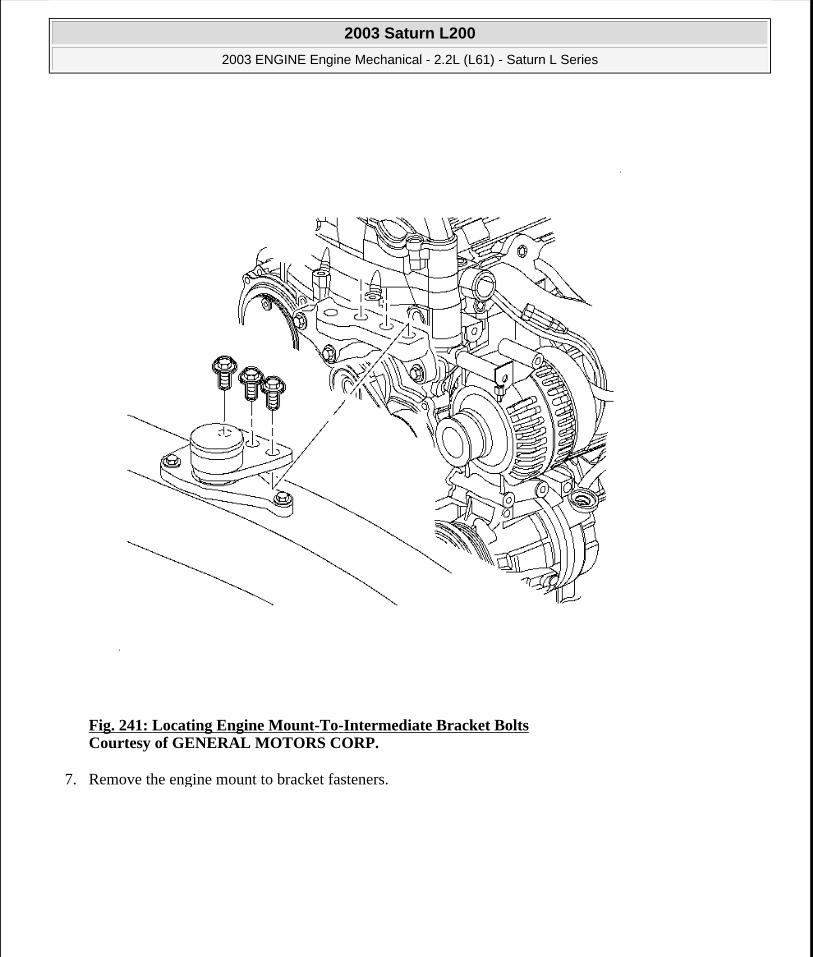
Fig. 241: Locating Engine Mount-To-Intermediate Bracket Bolts Courtesy of GENERAL MOTORS CORP.
7. Remove the engine mount to bracket fasteners.
2003 Saturn L200
2003 ENGINE Engine Mechanical - 2.2L (L61) - Saturn L Series
steve
Monday, May 09, 2011 12:52:04 PM Page 292 © 2006 Mitchell Repair Information Company, LLC.

Fig. 242: Removing & Installing Engine Mount Assembly Courtesy of GENERAL MOTORS CORP.
8. Remove the engine mount to body attachment fasteners.
9. Remove the engine mount from the vehicle.
2003 Saturn L200
2003 ENGINE Engine Mechanical - 2.2L (L61) - Saturn L Series
steve
Monday, May 09, 2011 12:52:04 PM Page 293 © 2006 Mitchell Repair Information Company, LLC.

Fig. 243: Removing & Installing Engine Mount Bracket Courtesy of GENERAL MOTORS CORP.
10. Remove the engine mount bracket to the engine fasteners.
11. Remove the bracket from the vehicle.
Installation Procedure
NOTE: Refer to FASTENER NOTICE in Cautions and Notices.
2003 Saturn L200
2003 ENGINE Engine Mechanical - 2.2L (L61) - Saturn L Series
steve
Monday, May 09, 2011 12:52:04 PM Page 294 © 2006 Mitchell Repair Information Company, LLC.

Fig. 244: Removing & Installing Engine Mount Bracket Courtesy of GENERAL MOTORS CORP.
1. Install the engine mount bracket into the vehicle and tighten the fasteners.
Tighten: Tighten the engine mount bracket-to-engine bolts to 90 N.m (66 lb ft).
2003 Saturn L200
2003 ENGINE Engine Mechanical - 2.2L (L61) - Saturn L Series
steve
Monday, May 09, 2011 12:52:04 PM Page 295 © 2006 Mitchell Repair Information Company, LLC.
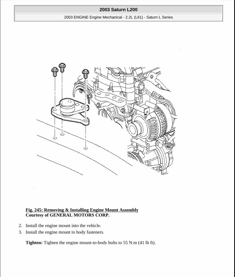
Fig. 245: Removing & Installing Engine Mount Assembly Courtesy of GENERAL MOTORS CORP.
2. Install the engine mount into the vehicle.
3. Install the engine mount to body fasteners.
Tighten: Tighten the engine mount-to-body bolts to 55 N.m (41 lb ft).
2003 Saturn L200
2003 ENGINE Engine Mechanical - 2.2L (L61) - Saturn L Series
steve
Monday, May 09, 2011 12:52:04 PM Page 296 © 2006 Mitchell Repair Information Company, LLC.
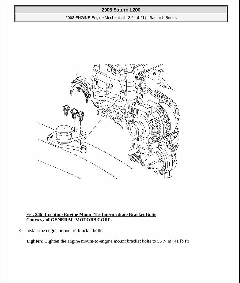
Fig. 246: Locating Engine Mount-To-Intermediate Bracket Bolts Courtesy of GENERAL MOTORS CORP.
4. Install the engine mount to bracket bolts.
Tighten: Tighten the engine mount-to-engine mount bracket bolts to 55 N.m (41 lb ft).
2003 Saturn L200
2003 ENGINE Engine Mechanical - 2.2L (L61) - Saturn L Series
steve
Monday, May 09, 2011 12:52:04 PM Page 297 © 2006 Mitchell Repair Information Company, LLC.

Fig. 247: Proper Installation Of Air Cleaner Assembly Courtesy of GENERAL MOTORS CORP.
5. Install the air cleaner assembly.
1. Install the air box. Ensure that the lower pin engages into the rubber mount grommet and that the lower duct fits into the resonator outlet.
2. Install the air box mount bolt.
3. Install the air cleaner.
2003 Saturn L200
2003 ENGINE Engine Mechanical - 2.2L (L61) - Saturn L Series
steve
Monday, May 09, 2011 12:52:04 PM Page 298 © 2006 Mitchell Repair Information Company, LLC.
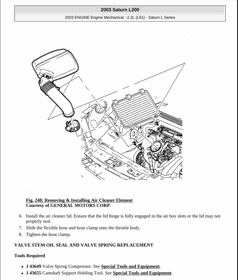
Fig. 248: Removing & Installing Air Cleaner Element Courtesy of GENERAL MOTORS CORP.
6. Install the air cleaner lid. Ensure that the lid hinge is fully engaged in the air box slots or the lid may not properly seal.
7. Slide the flexible hose and hose clamp onto the throttle body.
8. Tighten the hose clamp.
VALVE STEM OIL SEAL AND VALVE SPRING REPLACEMENT
Tools Required
J 43649 Valve Spring Compressor. See Special Tools and Equipment.
J 43655 Camshaft Support Holding Tool. See Special Tools and Equipment.
2003 Saturn L200
2003 ENGINE Engine Mechanical - 2.2L (L61) - Saturn L Series
steve
Monday, May 09, 2011 12:52:04 PM Page 299 © 2006 Mitchell Repair Information Company, LLC.

SA9102E-A Valve Seal Remover/Replacer. See Special Tools and Equipment.
SA9127E Gage Bar Set. See Special Tools and Equipment.
Removal Procedure
Fig. 249: Properly Installed Camshaft Support Holding Tool & Valve Spring Compressor Courtesy of GENERAL MOTORS CORP.
1. Remove the spark plugs, cam cover, and camshaft. Refer to Camshaft Cover Replacement.
2003 Saturn L200
2003 ENGINE Engine Mechanical - 2.2L (L61) - Saturn L Series
steve
Monday, May 09, 2011 12:52:04 PM Page 300 © 2006 Mitchell Repair Information Company, LLC.

Fig. 250: Installing Spark Plug Adapter Courtesy of GENERAL MOTORS CORP.
2. Install the J 43649 . Use 4 cam cover bolts to mount the supports to the cam cover threaded holes. See Special Tools and Equipment.
Tighten: Tighten the cam cover bolts-to-hold valve spring compressor to 10 N.m (89 lb in).
3. Install the spark plug adapter from the SA9127E in the respective cylinder. See Special Tools and Equipment.
IMPORTANT: During the camshaft removal procedure, the pistons are locked by the J 43655 and should not be rotated.
NOTE: Care should be used when servicing the valve spring, the retainer and the
2003 Saturn L200
2003 ENGINE Engine Mechanical - 2.2L (L61) - Saturn L Series
steve
Monday, May 09, 2011 12:52:04 PM Page 301 © 2006 Mitchell Repair Information Company, LLC.

4. Pressurize the cylinder being serviced to 690 kPa (100 psi).
5. Position the compressor assembly cover over the valve spring to be removed and turn the T-handle to compress the spring.
Fig. 251: Removing Valve Seal Courtesy of GENERAL MOTORS CORP.
6. Remove the valve spring cap, retainers, and release spring tension.
7. Remove the cap and spring.
8. Remove the valve stem seal using the SA9102E-A . See Special Tools and Equipment.
valve. If air pressure is lost, the valve(s) will drop into the cylinder.
2003 Saturn L200
2003 ENGINE Engine Mechanical - 2.2L (L61) - Saturn L Series
steve
Monday, May 09, 2011 12:52:04 PM Page 302 © 2006 Mitchell Repair Information Company, LLC.

Installation Procedure
Fig. 252: Inspecting Valve Seal Contact Area Courtesy of GENERAL MOTORS CORP.
NOTE: If a valve seal is removed after it has been installed, it must be discarded. The valve stem lock groove will cut the seal's lip during removal. Use extreme care when installing valve retainers and do not damage the valve stems.
IMPORTANT: Before each valve stem seal is installed, oil the valve stem seal and guide. If a valve stem seal is removed, it must be discarded.
2003 Saturn L200
2003 ENGINE Engine Mechanical - 2.2L (L61) - Saturn L Series
steve
Monday, May 09, 2011 12:52:04 PM Page 303 © 2006 Mitchell Repair Information Company, LLC.

1. Inspect the valve stem for scratches, scores, and scuffs. Spray the valve stem and guide with clean lubricating oil to remove any debris that may be present on the valve stem or the top of the guide.
Fig. 253: Installing Valve Stem Oil Seal Courtesy of GENERAL MOTORS CORP.
2. Oil the valve guide and valve stem. Install the valve stem oil seal with the SA9102E-A . See Special Tools and Equipment.
2003 Saturn L200
2003 ENGINE Engine Mechanical - 2.2L (L61) - Saturn L Series
steve
Monday, May 09, 2011 12:52:04 PM Page 304 © 2006 Mitchell Repair Information Company, LLC.

Fig. 254: Installing Valve Spring & Cap Courtesy of GENERAL MOTORS CORP.
3. Install the valve spring and cap.
2003 Saturn L200
2003 ENGINE Engine Mechanical - 2.2L (L61) - Saturn L Series
steve
Monday, May 09, 2011 12:52:04 PM Page 305 © 2006 Mitchell Repair Information Company, LLC.
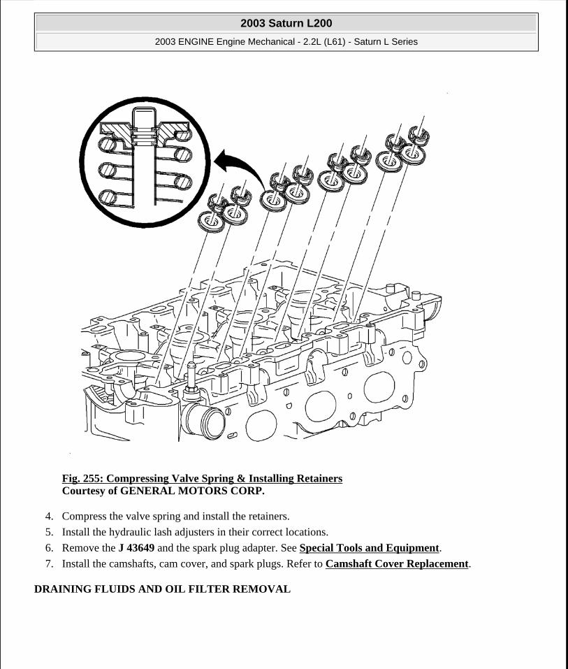
Fig. 255: Compressing Valve Spring & Installing Retainers Courtesy of GENERAL MOTORS CORP.
4. Compress the valve spring and install the retainers.
5. Install the hydraulic lash adjusters in their correct locations.
6. Remove the J 43649 and the spark plug adapter. See Special Tools and Equipment.
7. Install the camshafts, cam cover, and spark plugs. Refer to Camshaft Cover Replacement.
DRAINING FLUIDS AND OIL FILTER REMOVAL
2003 Saturn L200
2003 ENGINE Engine Mechanical - 2.2L (L61) - Saturn L Series
steve
Monday, May 09, 2011 12:52:04 PM Page 306 © 2006 Mitchell Repair Information Company, LLC.

Fig. 256: Identifying Oil Filter Housing Courtesy of GENERAL MOTORS CORP.
1. Remove the oil filter cap. Remove the oil pan drain plug and allow the oil to drain out.
2. Remove the oil filter from the cap and discard.
3. Clean the oil filter housing in the engine block.
4. Install the oil pan drain plug.
NOTE: Refer to FASTENER NOTICE in Cautions and Notices.
2003 Saturn L200
2003 ENGINE Engine Mechanical - 2.2L (L61) - Saturn L Series
steve
Monday, May 09, 2011 12:52:04 PM Page 307 © 2006 Mitchell Repair Information Company, LLC.

Tighten: Tighten the oil pan drain plug to 25 N.m (18 lb ft).
5. Remove the water pump drain plug from the water pump and allow the coolant to drain from the water pump.
6. Apply sealant P/N 21485278 to the water pump drain plug.
7. Install the water pump drain plug.
Tighten: Tighten the water pump drain plug to 20 N.m (15 lb ft).
8. If cleaning or repairing the engine block, it is not necessary to reinstall the plugs.
ENGINE FLYWHEEL REMOVAL
Tools Required
J 43653 Flywheel Holding Tool. See Special Tools and Equipment.
Removal Procedure
1. Remove the flywheel attaching bolts. Use the J 43653 to prevent crankshaft rotation. See Special Tools and Equipment.
IMPORTANT: It may be necessary to remove the chamfer (bevel) from the edge of an 18 mm socket in order to get full socket engagement on the thin headed flywheel bolts.
IMPORTANT: It is not necessary to orientate the flywheel to the crankshaft. It is balanced separately from the engine.
2003 Saturn L200
2003 ENGINE Engine Mechanical - 2.2L (L61) - Saturn L Series
steve
Monday, May 09, 2011 12:52:04 PM Page 308 © 2006 Mitchell Repair Information Company, LLC.
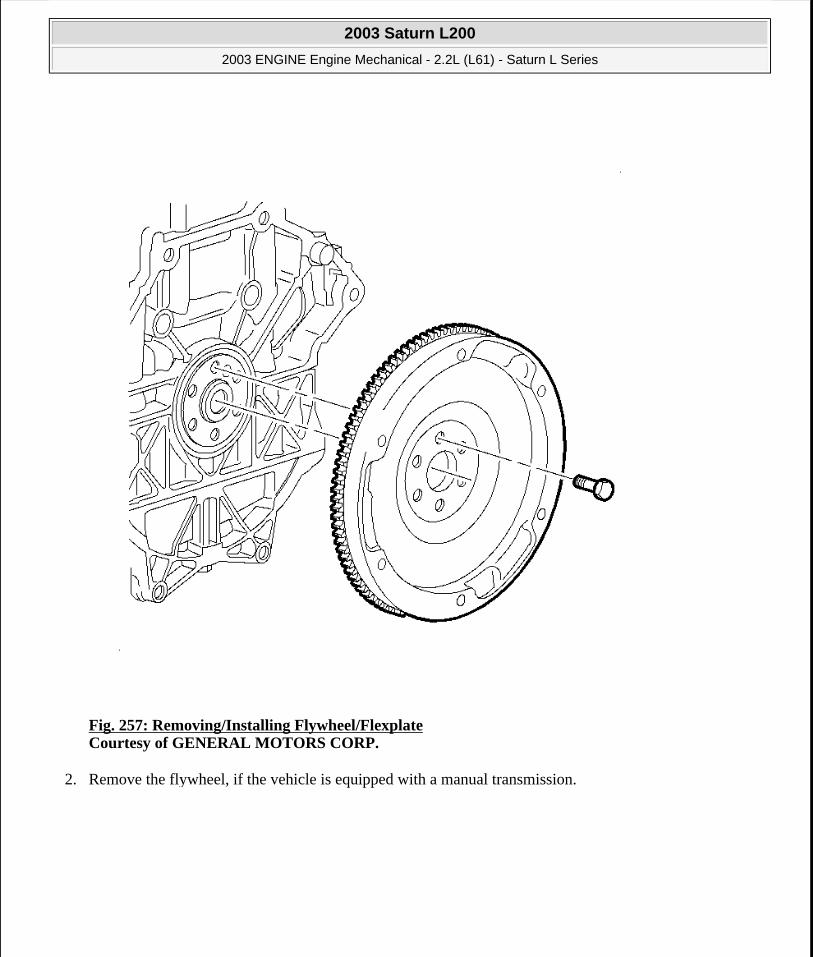
Fig. 257: Removing/Installing Flywheel/Flexplate Courtesy of GENERAL MOTORS CORP.
2. Remove the flywheel, if the vehicle is equipped with a manual transmission.
2003 Saturn L200
2003 ENGINE Engine Mechanical - 2.2L (L61) - Saturn L Series
steve
Monday, May 09, 2011 12:52:04 PM Page 309 © 2006 Mitchell Repair Information Company, LLC.
Fig. 258: Removing/Installing Flexplate/Flywheel Bolts Courtesy of GENERAL MOTORS CORP.
3. Remove the flywheel retainer and flywheel for vehicles equipped with an automatic transmission.
4. Clean the thread adhesive from the flywheel bolts. Use a nylon bristle brush to clean the bolt holes in the crankshaft.
EXHAUST MANIFOLD REMOVAL
Removal Procedure
2003 Saturn L200
2003 ENGINE Engine Mechanical - 2.2L (L61) - Saturn L Series
steve
Monday, May 09, 2011 12:52:04 PM Page 310 © 2006 Mitchell Repair Information Company, LLC.

Fig. 259: Identifying Air Pipe, Gasket, Bolts, & Nut Courtesy of GENERAL MOTORS CORP.
1. Remove the air pipe nut, if equipped.
2. Remove the air pipe bolts, if equipped.
3. Remove the air pipe, if equipped.
4. Remove the air pipe gasket, if equipped.
2003 Saturn L200
2003 ENGINE Engine Mechanical - 2.2L (L61) - Saturn L Series
steve
Monday, May 09, 2011 12:52:04 PM Page 311 © 2006 Mitchell Repair Information Company, LLC.

Fig. 260: Removing & Installing Exhaust Manifold & Gasket Courtesy of GENERAL MOTORS CORP.
5. Remove the exhaust manifold heat shield.
2003 Saturn L200
2003 ENGINE Engine Mechanical - 2.2L (L61) - Saturn L Series
steve
Monday, May 09, 2011 12:52:04 PM Page 312 © 2006 Mitchell Repair Information Company, LLC.

Fig. 261: Removing Engine Block Heater Courtesy of GENERAL MOTORS CORP.
6. Remove the engine block heater, if equipped.
7. Remove the heated oxygen sensor.
8. Remove the exhaust manifold to the cylinder head retaining nuts.
9. Remove the exhaust manifold.
10. Clean all sealing surfaces.
11. If the exhaust manifold is being replaced, transfer the following parts:
The exhaust manifold heat shield
The heated oxygen sensor
2003 Saturn L200
2003 ENGINE Engine Mechanical - 2.2L (L61) - Saturn L Series
steve
Monday, May 09, 2011 12:52:04 PM Page 313 © 2006 Mitchell Repair Information Company, LLC.

12. Replace the exhaust manifold nuts.
INTAKE MANIFOLD REMOVAL
Removal Procedure
Fig. 262: Disconnecting Fuel Pressure Regulator Hose Courtesy of GENERAL MOTORS CORP.
1. Disconnect the fuel pressure regulator hose from the throttle body and fuel rail.
2003 Saturn L200
2003 ENGINE Engine Mechanical - 2.2L (L61) - Saturn L Series
steve
Monday, May 09, 2011 12:52:04 PM Page 314 © 2006 Mitchell Repair Information Company, LLC.

Fig. 263: Removing & Installing Throttle Body Assembly Courtesy of GENERAL MOTORS CORP.
2. Remove the throttle body.
2003 Saturn L200
2003 ENGINE Engine Mechanical - 2.2L (L61) - Saturn L Series
steve
Monday, May 09, 2011 12:52:04 PM Page 315 © 2006 Mitchell Repair Information Company, LLC.

Fig. 264: Removing & Installing Fuel Rail Assembly Courtesy of GENERAL MOTORS CORP.
3. Remove the fuel pipes and clip.
4. Remove the fuel rail assembly.
2003 Saturn L200
2003 ENGINE Engine Mechanical - 2.2L (L61) - Saturn L Series
steve
Monday, May 09, 2011 12:52:04 PM Page 316 © 2006 Mitchell Repair Information Company, LLC.

Fig. 265: Removing Knock Sensor Courtesy of GENERAL MOTORS CORP.
5. Remove the knock sensor connector from the intake manifold.
6. Remove the knock sensor.
2003 Saturn L200
2003 ENGINE Engine Mechanical - 2.2L (L61) - Saturn L Series
steve
Monday, May 09, 2011 12:52:04 PM Page 317 © 2006 Mitchell Repair Information Company, LLC.

Fig. 266: Removing Intake Manifold Courtesy of GENERAL MOTORS CORP.
7. Remove the intake manifold retaining nuts and bolts.
8. Remove the intake manifold.
9. Remove the intake manifold gasket. The gasket is reusable if it is not damaged.
10. If the intake manifold needs to be replaced, transfer the following parts:
The throttle body
The body gasket. The manifold to throttle body gasket is reusable if it is not damaged.
CRANKSHAFT DAMPER REMOVAL
2003 Saturn L200
2003 ENGINE Engine Mechanical - 2.2L (L61) - Saturn L Series
steve
Monday, May 09, 2011 12:52:04 PM Page 318 © 2006 Mitchell Repair Information Company, LLC.

Tools Required
J 38122-A Crankshaft Pulley Holder
Removal Procedure
Fig. 267: Removing & Installing Harmonic Balancer Using Holder On Damper Assembly Courtesy of GENERAL MOTORS CORP.
1. Install the J 38122-A onto the damper assembly.
2. Remove and discard the damper retaining bolt and washer. Use the J 38122-A and breaker bar in order to prevent the crankshaft from rotating when loosening the bolt.
2003 Saturn L200
2003 ENGINE Engine Mechanical - 2.2L (L61) - Saturn L Series
steve
Monday, May 09, 2011 12:52:04 PM Page 319 © 2006 Mitchell Repair Information Company, LLC.
Fig. 268: Removing & Installing Damper Assembly Courtesy of GENERAL MOTORS CORP.
3. Remove the damper assembly.
CAMSHAFT COVER REMOVAL
Removal Procedure
2003 Saturn L200
2003 ENGINE Engine Mechanical - 2.2L (L61) - Saturn L Series
steve
Monday, May 09, 2011 12:52:04 PM Page 320 © 2006 Mitchell Repair Information Company, LLC.
Fig. 269: Removing Power Steering Pump Courtesy of GENERAL MOTORS CORP.
1. Remove the power steering pump, if equipped.
2003 Saturn L200
2003 ENGINE Engine Mechanical - 2.2L (L61) - Saturn L Series
steve
Monday, May 09, 2011 12:52:04 PM Page 321 © 2006 Mitchell Repair Information Company, LLC.

Fig. 270: Disconnecting/Connecting Ground Strap On The Camshaft Cover Assembly Courtesy of GENERAL MOTORS CORP.
2. Remove the camshaft cover grounding strap.
2003 Saturn L200
2003 ENGINE Engine Mechanical - 2.2L (L61) - Saturn L Series
steve
Monday, May 09, 2011 12:52:04 PM Page 322 © 2006 Mitchell Repair Information Company, LLC.

Fig. 271: Removing Front Lift Bracket Courtesy of GENERAL MOTORS CORP.
3. Remove the front lift bracket.
2003 Saturn L200
2003 ENGINE Engine Mechanical - 2.2L (L61) - Saturn L Series
steve
Monday, May 09, 2011 12:52:04 PM Page 323 © 2006 Mitchell Repair Information Company, LLC.
Fig. 272: Removing Rear Lift Bracket Courtesy of GENERAL MOTORS CORP.
4. Remove the rear lift bracket.
2003 Saturn L200
2003 ENGINE Engine Mechanical - 2.2L (L61) - Saturn L Series
steve
Monday, May 09, 2011 12:52:04 PM Page 324 © 2006 Mitchell Repair Information Company, LLC.

Fig. 273: Installing Ignition Module Assembly Courtesy of GENERAL MOTORS CORP.
5. Remove the ignition module and coil assembly.
2003 Saturn L200
2003 ENGINE Engine Mechanical - 2.2L (L61) - Saturn L Series
steve
Monday, May 09, 2011 12:52:04 PM Page 325 © 2006 Mitchell Repair Information Company, LLC.

Fig. 274: Removing & Installing Camshaft Cover Assembly Courtesy of GENERAL MOTORS CORP.
6. Remove the camshaft cover assembly.
ENGINE FRONT COVER AND OIL PUMP REMOVAL
2003 Saturn L200
2003 ENGINE Engine Mechanical - 2.2L (L61) - Saturn L Series
steve
Monday, May 09, 2011 12:52:04 PM Page 326 © 2006 Mitchell Repair Information Company, LLC.

Fig. 275: Removing & Installing Belt Tensioner Bolt Courtesy of GENERAL MOTORS CORP.
1. Remove the accessory drive belt tensioner.
2003 Saturn L200
2003 ENGINE Engine Mechanical - 2.2L (L61) - Saturn L Series
steve
Monday, May 09, 2011 12:52:04 PM Page 327 © 2006 Mitchell Repair Information Company, LLC.

Fig. 276: Installing Engine Front Cover Courtesy of GENERAL MOTORS CORP.
2. Remove the engine front cover bolts.
3. Remove the water pump bolt.
2003 Saturn L200
2003 ENGINE Engine Mechanical - 2.2L (L61) - Saturn L Series
steve
Monday, May 09, 2011 12:52:04 PM Page 328 © 2006 Mitchell Repair Information Company, LLC.

Fig. 277: Removing Engine Front Cover & Gaskets Courtesy of GENERAL MOTORS CORP.
4. Remove the engine front cover and gaskets.
5. Remove the crankshaft front cover oil seal using an oil seal removal tool.
TIMING CHAIN AND TENSIONER REMOVAL
Removal Procedure
2003 Saturn L200
2003 ENGINE Engine Mechanical - 2.2L (L61) - Saturn L Series
steve
Monday, May 09, 2011 12:52:04 PM Page 329 © 2006 Mitchell Repair Information Company, LLC.

Fig. 278: Removing Upper Timing Chain Guide Courtesy of GENERAL MOTORS CORP.
1. Remove the upper timing chain guide.
IMPORTANT: The timing chain tensioner must be removed to unload the chain tension before the timing chain is removed. If it is not, the timing chain will become misaligned and it will be difficult to remove.
2003 Saturn L200
2003 ENGINE Engine Mechanical - 2.2L (L61) - Saturn L Series
steve
Monday, May 09, 2011 12:52:04 PM Page 330 © 2006 Mitchell Repair Information Company, LLC.

Fig. 279: Removing Timing Chain Tensioner Courtesy of GENERAL MOTORS CORP.
2. Remove the timing chain tensioner plunger.
3. Locate the hex on the exhaust camshaft and hold with a 24 mm open-end wrench.
2003 Saturn L200
2003 ENGINE Engine Mechanical - 2.2L (L61) - Saturn L Series
steve
Monday, May 09, 2011 12:52:04 PM Page 331 © 2006 Mitchell Repair Information Company, LLC.

Fig. 280: Removing Exhaust Camshaft Sprocket Courtesy of GENERAL MOTORS CORP.
4. Remove the exhaust cam bolt and exhaust cam sprocket. Discard the bolt.
2003 Saturn L200
2003 ENGINE Engine Mechanical - 2.2L (L61) - Saturn L Series
steve
Monday, May 09, 2011 12:52:05 PM Page 332 © 2006 Mitchell Repair Information Company, LLC.

Fig. 281: Removing Adjustable Timing Chain Guide Courtesy of GENERAL MOTORS CORP.
5. Remove the adjustable timing chain guide.
2003 Saturn L200
2003 ENGINE Engine Mechanical - 2.2L (L61) - Saturn L Series
steve
Monday, May 09, 2011 12:52:05 PM Page 333 © 2006 Mitchell Repair Information Company, LLC.

Fig. 282: Fixed Timing Chain Guide Access Plug Courtesy of GENERAL MOTORS CORP.
6. Remove the plug to gain access to the fixed timing chain guide bolt.
2003 Saturn L200
2003 ENGINE Engine Mechanical - 2.2L (L61) - Saturn L Series
steve
Monday, May 09, 2011 12:52:05 PM Page 334 © 2006 Mitchell Repair Information Company, LLC.
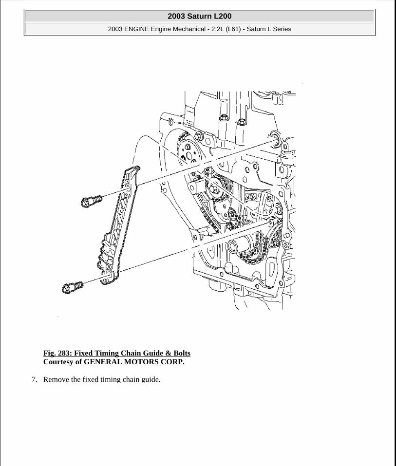
Fig. 283: Fixed Timing Chain Guide & Bolts Courtesy of GENERAL MOTORS CORP.
7. Remove the fixed timing chain guide.
2003 Saturn L200
2003 ENGINE Engine Mechanical - 2.2L (L61) - Saturn L Series
steve
Monday, May 09, 2011 12:52:05 PM Page 335 © 2006 Mitchell Repair Information Company, LLC.
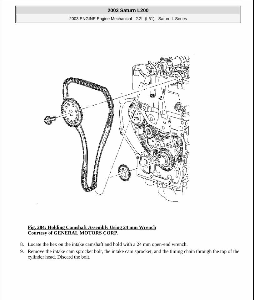
Fig. 284: Holding Camshaft Assembly Using 24 mm Wrench Courtesy of GENERAL MOTORS CORP.
8. Locate the hex on the intake camshaft and hold with a 24 mm open-end wrench.
9. Remove the intake cam sprocket bolt, the intake cam sprocket, and the timing chain through the top of the cylinder head. Discard the bolt.
2003 Saturn L200
2003 ENGINE Engine Mechanical - 2.2L (L61) - Saturn L Series
steve
Monday, May 09, 2011 12:52:05 PM Page 336 © 2006 Mitchell Repair Information Company, LLC.

Fig. 285: Installing Timing Chain Drive Sprocket Courtesy of GENERAL MOTORS CORP.
10. Remove the crankshaft sprocket.
2003 Saturn L200
2003 ENGINE Engine Mechanical - 2.2L (L61) - Saturn L Series
steve
Monday, May 09, 2011 12:52:05 PM Page 337 © 2006 Mitchell Repair Information Company, LLC.

Fig. 286: Removing & Installing Timing Chain Oiling Nozzle Courtesy of GENERAL MOTORS CORP.
11. Remove the oil nozzle and bolt.
INTAKE CAMSHAFT, FOLLOWER, AND ADJUSTER REMOVAL
Removal Procedure
2003 Saturn L200
2003 ENGINE Engine Mechanical - 2.2L (L61) - Saturn L Series
steve
Monday, May 09, 2011 12:52:05 PM Page 338 © 2006 Mitchell Repair Information Company, LLC.

Fig. 287: Removing Camshaft Bearing Caps Courtesy of GENERAL MOTORS CORP.
1. Mark the bearing caps to ensure they are installed in the same position.
2. Remove the intake camshaft bearing cap bolts.
3. Remove the camshaft bearing caps.
4. Remove the intake camshaft.
IMPORTANT: Remove each bolt on each cap 1 turn at a time until there is no spring tension on the camshaft.
2003 Saturn L200
2003 ENGINE Engine Mechanical - 2.2L (L61) - Saturn L Series
steve
Monday, May 09, 2011 12:52:05 PM Page 339 © 2006 Mitchell Repair Information Company, LLC.

Fig. 288: Installing Rocker Arms Courtesy of GENERAL MOTORS CORP.
5. Remove the intake camshaft roller finger followers.
IMPORTANT: Keep all of the roller finger followers and valve lash adjusters in order so that they can be reinstalled in their respective locations.
2003 Saturn L200
2003 ENGINE Engine Mechanical - 2.2L (L61) - Saturn L Series
steve
Monday, May 09, 2011 12:52:05 PM Page 340 © 2006 Mitchell Repair Information Company, LLC.

Fig. 289: Removing Hydraulic Element Adjusters Courtesy of GENERAL MOTORS CORP.
6. Remove the hydraulic element adjusters.
EXHAUST CAMSHAFT, FOLLOWER, AND ADJUSTER REMOVAL
Removal Procedure
2003 Saturn L200
2003 ENGINE Engine Mechanical - 2.2L (L61) - Saturn L Series
steve
Monday, May 09, 2011 12:52:05 PM Page 341 © 2006 Mitchell Repair Information Company, LLC.
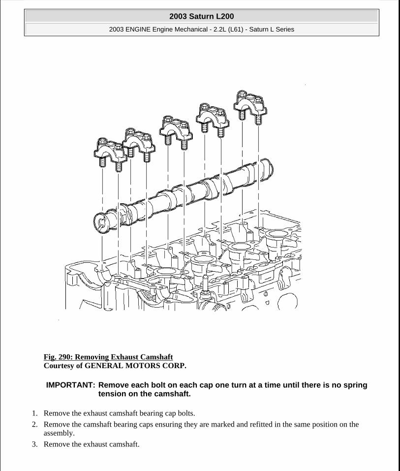
Fig. 290: Removing Exhaust Camshaft Courtesy of GENERAL MOTORS CORP.
1. Remove the exhaust camshaft bearing cap bolts.
2. Remove the camshaft bearing caps ensuring they are marked and refitted in the same position on the assembly.
3. Remove the exhaust camshaft.
IMPORTANT: Remove each bolt on each cap one turn at a time until there is no spring tension on the camshaft.
2003 Saturn L200
2003 ENGINE Engine Mechanical - 2.2L (L61) - Saturn L Series
steve
Monday, May 09, 2011 12:52:05 PM Page 342 © 2006 Mitchell Repair Information Company, LLC.
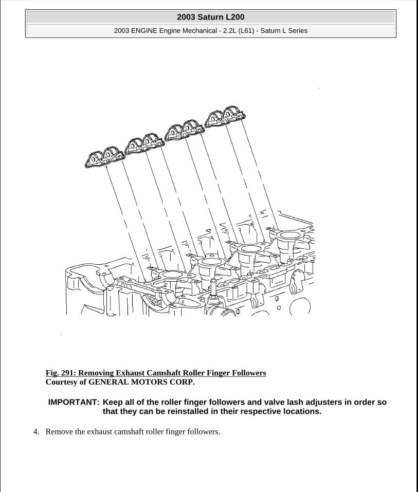
Fig. 291: Removing Exhaust Camshaft Roller Finger Followers Courtesy of GENERAL MOTORS CORP.
4. Remove the exhaust camshaft roller finger followers.
IMPORTANT: Keep all of the roller finger followers and valve lash adjusters in order so that they can be reinstalled in their respective locations.
2003 Saturn L200
2003 ENGINE Engine Mechanical - 2.2L (L61) - Saturn L Series
steve
Monday, May 09, 2011 12:52:05 PM Page 343 © 2006 Mitchell Repair Information Company, LLC.

Fig. 292: Removing Hydraulic Element Adjusters Courtesy of GENERAL MOTORS CORP.
5. Remove the hydraulic element adjusters.
BALANCE SHAFT DRIVE CHAIN AND TENSIONER REMOVAL
Removal Procedure
2003 Saturn L200
2003 ENGINE Engine Mechanical - 2.2L (L61) - Saturn L Series
steve
Monday, May 09, 2011 12:52:05 PM Page 344 © 2006 Mitchell Repair Information Company, LLC.
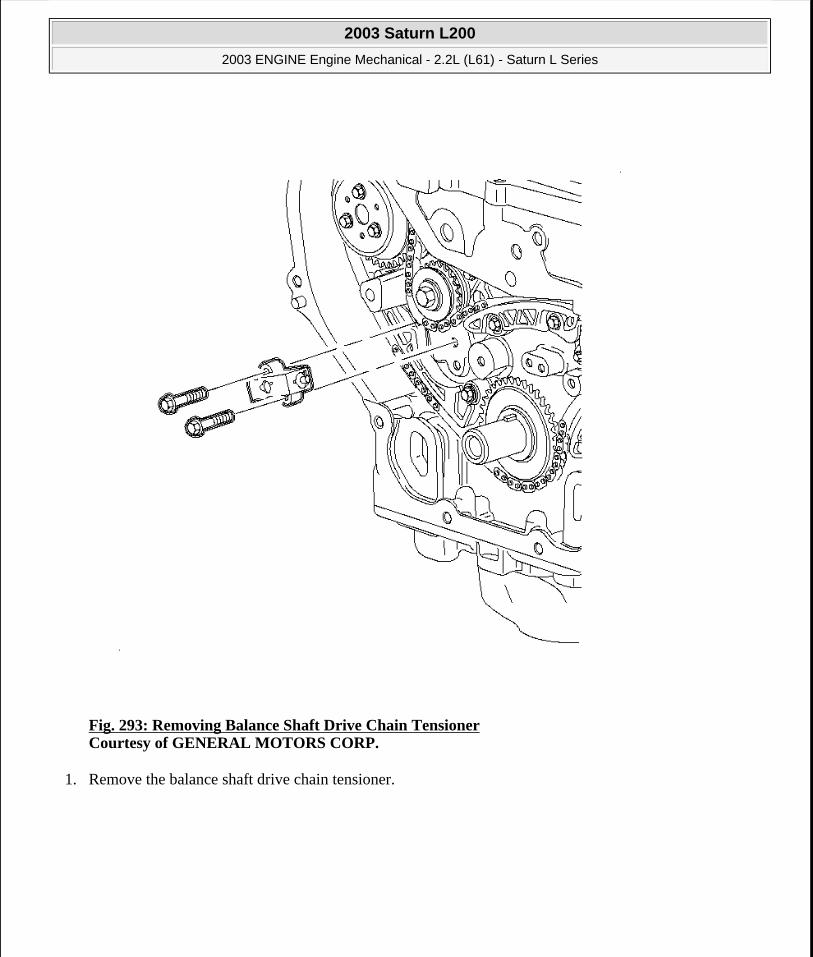
Fig. 293: Removing Balance Shaft Drive Chain Tensioner Courtesy of GENERAL MOTORS CORP.
1. Remove the balance shaft drive chain tensioner.
2003 Saturn L200
2003 ENGINE Engine Mechanical - 2.2L (L61) - Saturn L Series
steve
Monday, May 09, 2011 12:52:05 PM Page 345 © 2006 Mitchell Repair Information Company, LLC.

Fig. 294: Removing Adjustable Balance Shaft Chain Guide Courtesy of GENERAL MOTORS CORP.
2. Remove the adjustable balance shaft chain guide.
2003 Saturn L200
2003 ENGINE Engine Mechanical - 2.2L (L61) - Saturn L Series
steve
Monday, May 09, 2011 12:52:05 PM Page 346 © 2006 Mitchell Repair Information Company, LLC.

Fig. 295: Removing Small Balance Shaft Drive Chain Guide Courtesy of GENERAL MOTORS CORP.
3. Remove the small balance shaft drive chain guide.
2003 Saturn L200
2003 ENGINE Engine Mechanical - 2.2L (L61) - Saturn L Series
steve
Monday, May 09, 2011 12:52:05 PM Page 347 © 2006 Mitchell Repair Information Company, LLC.

Fig. 296: Removing Upper Balance Shaft Drive Chain Guide Courtesy of GENERAL MOTORS CORP.
4. Remove the upper balance shaft drive chain guide.
2003 Saturn L200
2003 ENGINE Engine Mechanical - 2.2L (L61) - Saturn L Series
steve
Monday, May 09, 2011 12:52:05 PM Page 348 © 2006 Mitchell Repair Information Company, LLC.

Fig. 297: Removing Balance Shaft Drive Chain Courtesy of GENERAL MOTORS CORP.
5. Remove the balance shaft drive chain.
6. Remove the crankshaft drive sprocket.
BALANCE SHAFT REMOVAL
Tools Required
IMPORTANT: It may ease the removal of the balance shaft drive chain to get all of the slack in the chain between the crankshaft and water pump sprockets.
2003 Saturn L200
2003 ENGINE Engine Mechanical - 2.2L (L61) - Saturn L Series
steve
Monday, May 09, 2011 12:52:05 PM Page 349 © 2006 Mitchell Repair Information Company, LLC.

J 43650 Balance Shaft Bearing Remover/Installer. See Special Tools and Equipment.
Removal Procedure
Fig. 298: Removing Balance Shaft Bearing Carrier Bolts Courtesy of GENERAL MOTORS CORP.
1. Remove the balance shaft bearing carrier bolts.
IMPORTANT: It is possible to install the intake side balance shaft into the exhaust side and vice versa. Use care not to install the balance shafts into the wrong bores. Engine vibration will result.
2003 Saturn L200
2003 ENGINE Engine Mechanical - 2.2L (L61) - Saturn L Series
steve
Monday, May 09, 2011 12:52:05 PM Page 350 © 2006 Mitchell Repair Information Company, LLC.

2. Remove the balance shaft assemblies.
Fig. 299: Installing J 43650 Courtesy of GENERAL MOTORS CORP.
3. Install the J 43650 into the balance shaft hole. Insert the tool with the foot parallel to the shaft. See Special Tools and Equipment.
IMPORTANT: Do not remove the front balance shaft bearing bolt.
NOTE: Proper centering of the tool is required on the balance shaft bushing. If the tool is not properly centered, then damage to the bearing bore and block will occur.
2003 Saturn L200
2003 ENGINE Engine Mechanical - 2.2L (L61) - Saturn L Series
steve
Monday, May 09, 2011 12:52:05 PM Page 351 © 2006 Mitchell Repair Information Company, LLC.
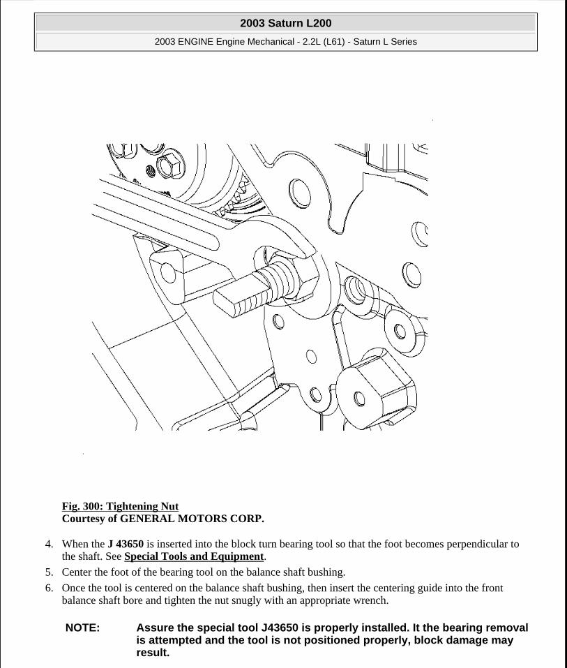
Fig. 300: Tightening Nut Courtesy of GENERAL MOTORS CORP.
4. When the J 43650 is inserted into the block turn bearing tool so that the foot becomes perpendicular to the shaft. See Special Tools and Equipment.
5. Center the foot of the bearing tool on the balance shaft bushing.
6. Once the tool is centered on the balance shaft bushing, then insert the centering guide into the front balance shaft bore and tighten the nut snugly with an appropriate wrench.
NOTE: Assure the special tool J43650 is properly installed. It the bearing removal is attempted and the tool is not positioned properly, block damage may result.
2003 Saturn L200
2003 ENGINE Engine Mechanical - 2.2L (L61) - Saturn L Series
steve
Monday, May 09, 2011 12:52:05 PM Page 352 © 2006 Mitchell Repair Information Company, LLC.

7. To assure the J 43650 is properly installed, measure from one end of the front side of the nut to the end of the threaded shaft. See Special Tools and Equipment. The measurement should be between 74-77 mm (2.91-3.03 in). If the measurement is less than 73 mm (2.87 in) the tool is not properly installed and should be reinstalled.
Fig. 301: Tightening Nut on Bearing Tool Courtesy of GENERAL MOTORS CORP.
8. Tighten the nut on the bearing tool until the tension releases. When the tension releases, remove the bearing tool and the balance shaft bushings.
WATER PUMP REMOVAL
2003 Saturn L200
2003 ENGINE Engine Mechanical - 2.2L (L61) - Saturn L Series
steve
Monday, May 09, 2011 12:52:05 PM Page 353 © 2006 Mitchell Repair Information Company, LLC.

Removal Procedure
Fig. 302: Installing ECT Sensor Courtesy of GENERAL MOTORS CORP.
1. Remove the engine coolant temperature sensor.
2003 Saturn L200
2003 ENGINE Engine Mechanical - 2.2L (L61) - Saturn L Series
steve
Monday, May 09, 2011 12:52:05 PM Page 354 © 2006 Mitchell Repair Information Company, LLC.

Fig. 303: Removing Thermostat Housing & Thermostat Element Courtesy of GENERAL MOTORS CORP.
2. Remove the thermostat and water feed pipe retaining bolts.
3. Remove the thermostat housing and water feed pipe from the water pump.
IMPORTANT: Twist the water feed pipe while pulling to remove it from the water pump.
2003 Saturn L200
2003 ENGINE Engine Mechanical - 2.2L (L61) - Saturn L Series
steve
Monday, May 09, 2011 12:52:05 PM Page 355 © 2006 Mitchell Repair Information Company, LLC.

Fig. 304: Removing Water Pump Assembly Courtesy of GENERAL MOTORS CORP.
4. Remove the water pump retaining bolts.
5. Remove the water pump assembly.
CYLINDER HEAD REMOVAL
Tools Required
IMPORTANT: Be sure to remove the bolt that goes through the front of the engine block.
2003 Saturn L200
2003 ENGINE Engine Mechanical - 2.2L (L61) - Saturn L Series
steve
Monday, May 09, 2011 12:52:05 PM Page 356 © 2006 Mitchell Repair Information Company, LLC.
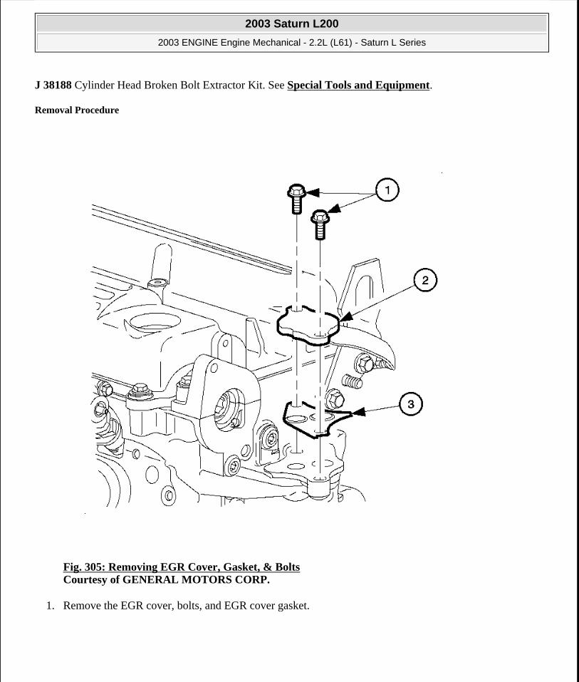
J 38188 Cylinder Head Broken Bolt Extractor Kit. See Special Tools and Equipment.
Removal Procedure
Fig. 305: Removing EGR Cover, Gasket, & Bolts Courtesy of GENERAL MOTORS CORP.
1. Remove the EGR cover, bolts, and EGR cover gasket.
2003 Saturn L200
2003 ENGINE Engine Mechanical - 2.2L (L61) - Saturn L Series
steve
Monday, May 09, 2011 12:52:05 PM Page 357 © 2006 Mitchell Repair Information Company, LLC.

Fig. 306: Removing Cylinder Head Bolts Using Loosening Sequence Courtesy of GENERAL MOTORS CORP.
2. Remove the cylinder head to block bolts using the loosening sequence. Discard the used bolts.
2003 Saturn L200
2003 ENGINE Engine Mechanical - 2.2L (L61) - Saturn L Series
steve
Monday, May 09, 2011 12:52:05 PM Page 358 © 2006 Mitchell Repair Information Company, LLC.
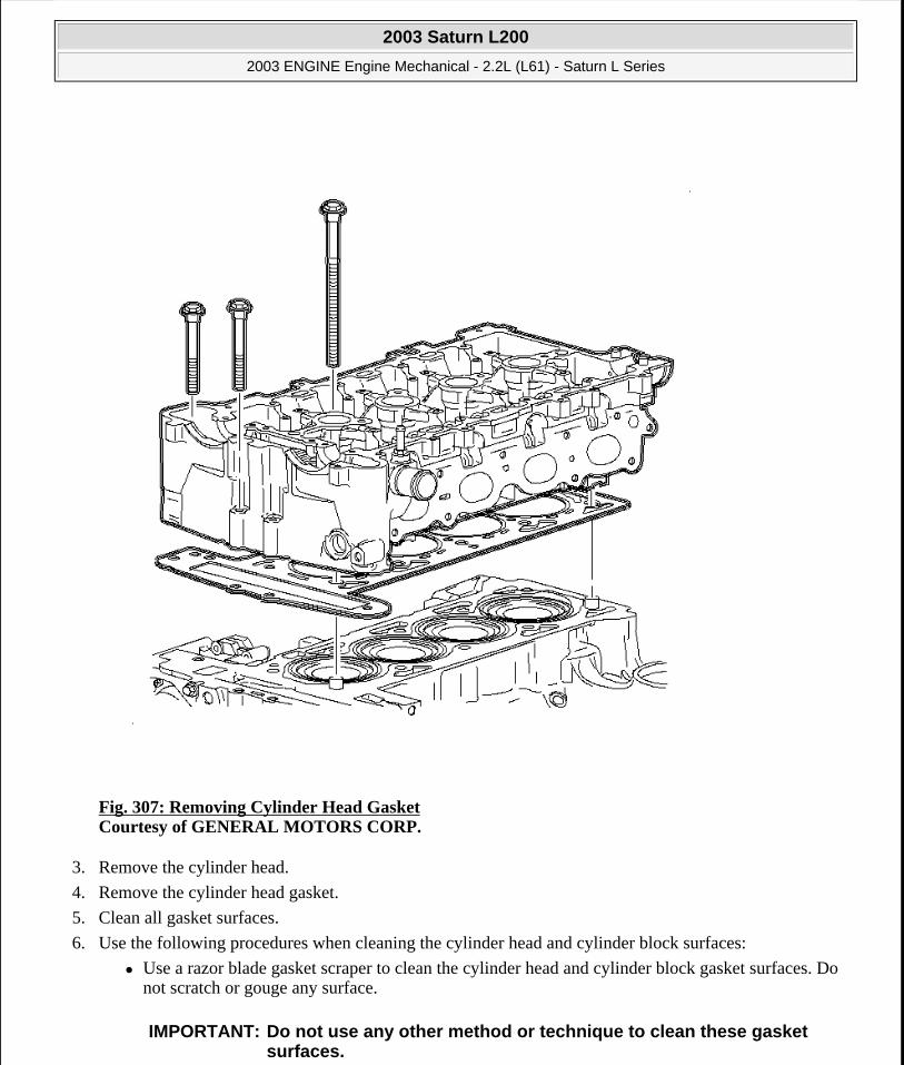
Fig. 307: Removing Cylinder Head Gasket Courtesy of GENERAL MOTORS CORP.
3. Remove the cylinder head.
4. Remove the cylinder head gasket.
5. Clean all gasket surfaces.
6. Use the following procedures when cleaning the cylinder head and cylinder block surfaces:
Use a razor blade gasket scraper to clean the cylinder head and cylinder block gasket surfaces. Do not scratch or gouge any surface.
IMPORTANT: Do not use any other method or technique to clean these gasket surfaces.
2003 Saturn L200
2003 ENGINE Engine Mechanical - 2.2L (L61) - Saturn L Series
steve
Monday, May 09, 2011 12:52:05 PM Page 359 © 2006 Mitchell Repair Information Company, LLC.

Use a new razor blade for each cylinder head and cylinder block.
Hold the razor blade as parallel to the gasket surface as possible.
7. Clean the old sealer/lube and dirt from bolts, studs, and cylinder head bolt holes.
8. Clean the bolt holes with a nylon bristle brush.
9. When cleaning the cylinder head bolt holes use a suitable commercial spray liquid solvent and compressed air from an extended-tip blow gun to reach the bottom of the holes.
10. Remove any broken long cylinder head bolts using the J 38188 . See Special Tools and Equipment.
OIL PAN REMOVAL
Removal Procedure
IMPORTANT: Be careful not to gouge or scratch the gasket surfaces. Do not gouge or scrape the combustion chamber surfaces. The feel of the gasket surface is important, not the appearance. There will be indentations from the gasket left in the cylinder head after all the gasket material is removed. These small indentations will be filled in by the new gasket.
IMPORTANT: Do not use a tap to clean the cylinder head bolt holes. Use a nylon bristle brush.
CAUTION: Wear safety glasses to avoid injury when using compressed air or any cleaning solvent. Bodily injury may occur if fumes are inhaled or if skin is exposed to chemicals.
2003 Saturn L200
2003 ENGINE Engine Mechanical - 2.2L (L61) - Saturn L Series
steve
Monday, May 09, 2011 12:52:05 PM Page 360 © 2006 Mitchell Repair Information Company, LLC.

Fig. 308: Removing Engine Oil Pan Bolts Courtesy of GENERAL MOTORS CORP.
1. Remove the oil pan bolts.
2. Remove the oil pan at the pry points.
PISTON, CONNECTING ROD, AND BEARING REMOVAL
Tools Required
J 41742 Connecting Rod Guide. See Special Tools and Equipment.
Removal Procedure
2003 Saturn L200
2003 ENGINE Engine Mechanical - 2.2L (L61) - Saturn L Series
steve
Monday, May 09, 2011 12:52:05 PM Page 361 © 2006 Mitchell Repair Information Company, LLC.
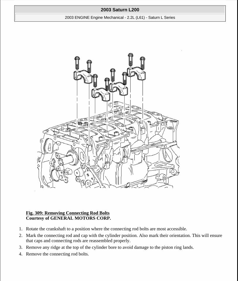
Fig. 309: Removing Connecting Rod Bolts Courtesy of GENERAL MOTORS CORP.
1. Rotate the crankshaft to a position where the connecting rod bolts are most accessible.
2. Mark the connecting rod and cap with the cylinder position. Also mark their orientation. This will ensure that caps and connecting rods are reassembled properly.
3. Remove any ridge at the top of the cylinder bore to avoid damage to the piston ring lands.
4. Remove the connecting rod bolts.
2003 Saturn L200
2003 ENGINE Engine Mechanical - 2.2L (L61) - Saturn L Series
steve
Monday, May 09, 2011 12:52:05 PM Page 362 © 2006 Mitchell Repair Information Company, LLC.

Fig. 310: Removing Connecting Rod Cap Courtesy of GENERAL MOTORS CORP.
5. Remove the connecting rod cap.
6. Install the J 41742 in the connecting rod bolt holes before removing the piston and connecting rod assembly. See Special Tools and Equipment.
7. Remove the piston and connecting rod assembly.
8. Complete steps 2-7 for the remaining pistons and connecting rods.
LOWER CRANKCASE REMOVAL
Removal Procedure
2003 Saturn L200
2003 ENGINE Engine Mechanical - 2.2L (L61) - Saturn L Series
steve
Monday, May 09, 2011 12:52:05 PM Page 363 © 2006 Mitchell Repair Information Company, LLC.
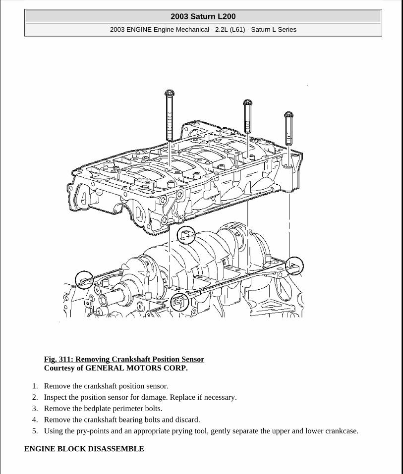
Fig. 311: Removing Crankshaft Position Sensor Courtesy of GENERAL MOTORS CORP.
1. Remove the crankshaft position sensor.
2. Inspect the position sensor for damage. Replace if necessary.
3. Remove the bedplate perimeter bolts.
4. Remove the crankshaft bearing bolts and discard.
5. Using the pry-points and an appropriate prying tool, gently separate the upper and lower crankcase.
ENGINE BLOCK DISASSEMBLE
2003 Saturn L200
2003 ENGINE Engine Mechanical - 2.2L (L61) - Saturn L Series
steve
Monday, May 09, 2011 12:52:05 PM Page 364 © 2006 Mitchell Repair Information Company, LLC.
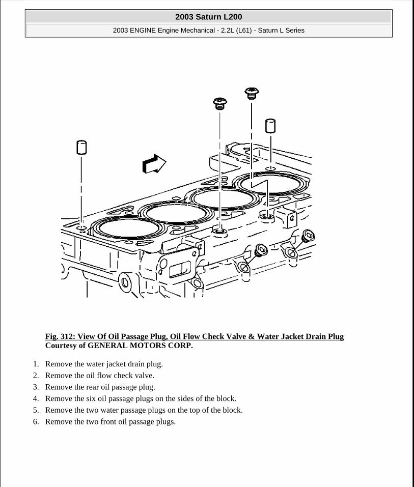
Fig. 312: View Of Oil Passage Plug, Oil Flow Check Valve & Water Jacket Drain Plug Courtesy of GENERAL MOTORS CORP.
1. Remove the water jacket drain plug.
2. Remove the oil flow check valve.
3. Remove the rear oil passage plug.
4. Remove the six oil passage plugs on the sides of the block.
5. Remove the two water passage plugs on the top of the block.
6. Remove the two front oil passage plugs.
2003 Saturn L200
2003 ENGINE Engine Mechanical - 2.2L (L61) - Saturn L Series
steve
Monday, May 09, 2011 12:52:05 PM Page 365 © 2006 Mitchell Repair Information Company, LLC.

Fig. 313: View of Knock Sensor Courtesy of GENERAL MOTORS CORP.
7. Remove the knock sensor and bolt.
2003 Saturn L200
2003 ENGINE Engine Mechanical - 2.2L (L61) - Saturn L Series
steve
Monday, May 09, 2011 12:52:05 PM Page 366 © 2006 Mitchell Repair Information Company, LLC.

Fig. 314: View Of Engine Oil Pressure Sensor Courtesy of GENERAL MOTORS CORP.
8. Remove the oil pressure switch.
2003 Saturn L200
2003 ENGINE Engine Mechanical - 2.2L (L61) - Saturn L Series
steve
Monday, May 09, 2011 12:52:05 PM Page 367 © 2006 Mitchell Repair Information Company, LLC.
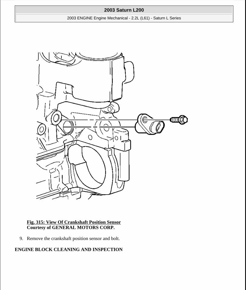
Fig. 315: View Of Crankshaft Position Sensor Courtesy of GENERAL MOTORS CORP.
9. Remove the crankshaft position sensor and bolt.
ENGINE BLOCK CLEANING AND INSPECTION
2003 Saturn L200
2003 ENGINE Engine Mechanical - 2.2L (L61) - Saturn L Series
steve
Monday, May 09, 2011 12:52:05 PM Page 368 © 2006 Mitchell Repair Information Company, LLC.

Fig. 316: Cleaning Engine Block & Lower Crankcase Courtesy of GENERAL MOTORS CORP.
1. Clean the sealing material from the gasket mating surfaces.
2. Clean the engine block and lower crankcase in a cleaning tank with solvent appropriate for aluminum.
3. Flush the engine block with clean water or steam.
4. Clean the oil passages.
5. Clean the blind holes.
6. Spray the cylinder bores and the machined surfaces with engine oil.
7. Inspect the threaded holes. Clean the threaded holes with a rifle brush. If necessary, drill out the holes and install thread inserts. Refer to Thread Repair.
2003 Saturn L200
2003 ENGINE Engine Mechanical - 2.2L (L61) - Saturn L Series
steve
Monday, May 09, 2011 12:52:05 PM Page 369 © 2006 Mitchell Repair Information Company, LLC.

Fig. 317: Checking Deck Surface For Flatness Courtesy of GENERAL MOTORS CORP.
8. Use a straight edge and a feeler gage to check the deck surface for flatness. Carefully machine minor irregularities. Replace the block if more than 0.254 mm (0.010 in) must be removed.
9. Inspect the oil pan rail for nicks. Inspect the front cover attaching area for nicks. Use a flat mill file to remove any nicks.
IMPORTANT: Do not attempt to machine the lower crankcase to engine block surfaces.
2003 Saturn L200
2003 ENGINE Engine Mechanical - 2.2L (L61) - Saturn L Series
steve
Monday, May 09, 2011 12:52:05 PM Page 370 © 2006 Mitchell Repair Information Company, LLC.
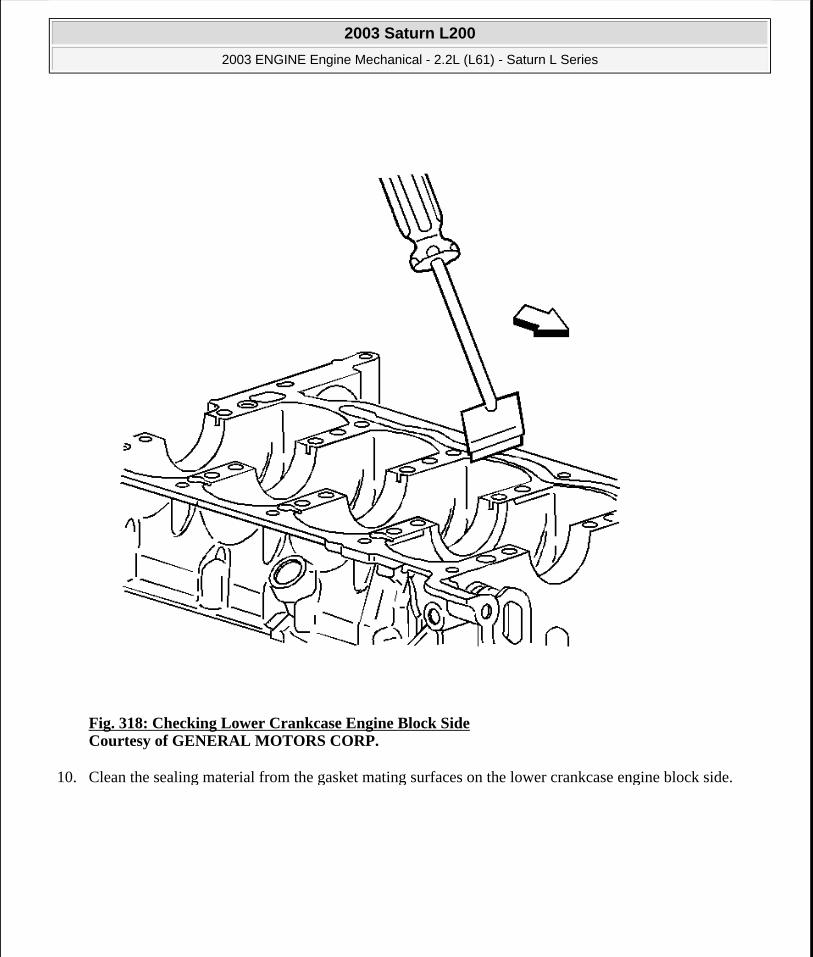
Fig. 318: Checking Lower Crankcase Engine Block Side Courtesy of GENERAL MOTORS CORP.
10. Clean the sealing material from the gasket mating surfaces on the lower crankcase engine block side.
2003 Saturn L200
2003 ENGINE Engine Mechanical - 2.2L (L61) - Saturn L Series
steve
Monday, May 09, 2011 12:52:05 PM Page 371 © 2006 Mitchell Repair Information Company, LLC.

Fig. 319: Checking Lower Crankcase Oil Pan Side Courtesy of GENERAL MOTORS CORP.
11. Clean the sealing material from the gasket mating surfaces on the lower crankcase oil pan side.
2003 Saturn L200
2003 ENGINE Engine Mechanical - 2.2L (L61) - Saturn L Series
steve
Monday, May 09, 2011 12:52:05 PM Page 372 © 2006 Mitchell Repair Information Company, LLC.

Fig. 320: Checking Crankshaft Flange Runout Courtesy of GENERAL MOTORS CORP.
12. Inspect the mating surfaces of the transmission face.
13. Use the following procedure in order to measure the engine block flange runout at the mounting bolt hole bosses:
1. Temporarily install the crankshaft. Measure the crankshaft flange runout.
2. Hold the gage plate flat against the crankshaft flange.
NOTE: A broken flywheel may result if the transmission case mating surface is not flat.
2003 Saturn L200
2003 ENGINE Engine Mechanical - 2.2L (L61) - Saturn L Series
steve
Monday, May 09, 2011 12:52:05 PM Page 373 © 2006 Mitchell Repair Information Company, LLC.

3. Place the dial indicator stem on the transmission mounting bolt hole boss. Set the indicator to 0.
4. Record the readings obtained from all of the bolt hole bosses. The measurements should not vary more than 0.203 mm (0.008 in).
5. Recheck the crankshaft flange runout if the readings vary more than 0.203 mm (0.008 in).
Fig. 321: Inspecting Crankshaft Main Bearing Bores Courtesy of GENERAL MOTORS CORP.
14. Inspect the crankshaft main bearing bores. Use a bore gage to measure the bearing bore concentricity and alignment.
15. Replace the engine block and bed plate if the crankshaft bearing bores are out of specification.
2003 Saturn L200
2003 ENGINE Engine Mechanical - 2.2L (L61) - Saturn L Series
steve
Monday, May 09, 2011 12:52:05 PM Page 374 © 2006 Mitchell Repair Information Company, LLC.

Fig. 322: Inspecting Cylinder Bores Using J 8087 Courtesy of GENERAL MOTORS CORP.
16. Inspect the cylinder bores. Inspect for the following items:
Wear
Taper
Runout
Ridging
CRANKSHAFT BALANCER CLEANING AND INSPECTION
2003 Saturn L200
2003 ENGINE Engine Mechanical - 2.2L (L61) - Saturn L Series
steve
Monday, May 09, 2011 12:52:05 PM Page 375 © 2006 Mitchell Repair Information Company, LLC.

Fig. 323: View of Crankshaft Balancer Courtesy of GENERAL MOTORS CORP.
1. Clean the crankshaft balancer.
2. Clean the belt grooves of all dirt or debris with a wire brush.
3. Dry the crankshaft balancer with compressed air.
4. Inspect the crankshaft balancer for the following:
Worn, grooved, or damaged hub seal surface
CAUTION: Refer to SAFETY GLASSES & COMPRESSED AIR CAUTION in Cautions and Notices.
2003 Saturn L200
2003 ENGINE Engine Mechanical - 2.2L (L61) - Saturn L Series
steve
Monday, May 09, 2011 12:52:05 PM Page 376 © 2006 Mitchell Repair Information Company, LLC.

A crankshaft balancer hub seal surface with excessive scoring, grooves, rust, or other damage must be replaced.
Worn, clunking, or deteriorated rubber between the pulley and damper ring
Dirty or damaged belt grooves
The balancer belt grooves should be free of any nicks, gouges, or other damage that may not allow the belt to track properly.
Minor imperfections may be removed with a fine file.
ENGINE FLYWHEEL CLEANING AND INSPECTION
IMPORTANT: In order for the belt to track properly, the belt grooves should be free of all dirt or debris.
2003 Saturn L200
2003 ENGINE Engine Mechanical - 2.2L (L61) - Saturn L Series
steve
Monday, May 09, 2011 12:52:05 PM Page 377 © 2006 Mitchell Repair Information Company, LLC.
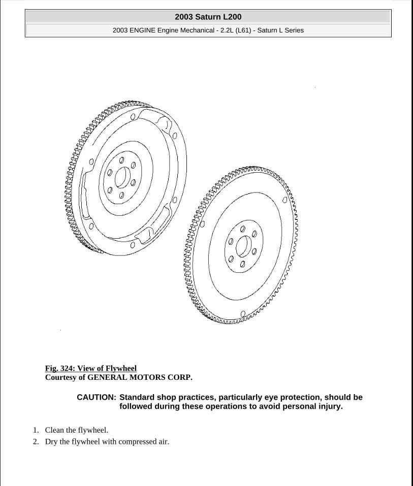
Fig. 324: View of Flywheel Courtesy of GENERAL MOTORS CORP.
1. Clean the flywheel.
2. Dry the flywheel with compressed air.
CAUTION: Standard shop practices, particularly eye protection, should be followed during these operations to avoid personal injury.
2003 Saturn L200
2003 ENGINE Engine Mechanical - 2.2L (L61) - Saturn L Series
steve
Monday, May 09, 2011 12:52:05 PM Page 378 © 2006 Mitchell Repair Information Company, LLC.

Fig. 325: Removing/Installing Flywheel/Flexplate Courtesy of GENERAL MOTORS CORP.
3. Inspect the manual transmission flywheel for the following:
Damaged ring gear teeth
Loose or improperly positioned ring gear
The ring gear has an interference fit onto the flywheel and should be positioned completely against the flange of the flywheel.
A scored, grooved, or damaged friction surface
2003 Saturn L200
2003 ENGINE Engine Mechanical - 2.2L (L61) - Saturn L Series
steve
Monday, May 09, 2011 12:52:05 PM Page 379 © 2006 Mitchell Repair Information Company, LLC.

Fig. 326: Removing/Installing Flexplate/Flywheel Bolts Courtesy of GENERAL MOTORS CORP.
4. Inspect the automatic transmission flywheel for the following:
Damaged ring gear teeth
Stress cracks around the flywheel-to-crankshaft bolt hole locations and weight saving holes
CYLINDER HONING
2003 Saturn L200
2003 ENGINE Engine Mechanical - 2.2L (L61) - Saturn L Series
steve
Monday, May 09, 2011 12:52:05 PM Page 380 © 2006 Mitchell Repair Information Company, LLC.

Fig. 327: Measuring Cylinder Bore Courtesy of GENERAL MOTORS CORP.
1. Measure the cylinder bore for out-of-round and taper.
2. Measure dimension (1) at 13 mm (1/2 in) below the head gasket surface. Measure dimension (2) at 100 mm (4 in) below the head gasket surface.
2003 Saturn L200
2003 ENGINE Engine Mechanical - 2.2L (L61) - Saturn L Series
steve
Monday, May 09, 2011 12:52:06 PM Page 381 © 2006 Mitchell Repair Information Company, LLC.

Fig. 328: Measuring Bore Gauge With Micrometer Courtesy of GENERAL MOTORS CORP.
3. Measure the cylinder bores by setting the cylinder gauge dial at zero in the cylinder at the point of the desired measurement. Lock the dial indicator at zero before removing the dial from the cylinder. Measure across the gauge contact points with an outside micrometer, with the gauge at the same zero setting as when the gauge was removed from the cylinder.
4. Fine vertical scratches made by the ring ends do not, by themselves, cause excessive oil consumption. Do not hone the cylinder in order to remove these scratches.
5. If the bore is glazed but otherwise serviceable, lightly break the glaze with a hone. Replace the piston rings. Refer to Piston, Connecting Rod, and Bearing Installation.
The honing stones must be clean, sharp, and straight.
Move the hone slowly up and down to produce a 45 degree cross hatch pattern.
Clean the bore thoroughly with soap and water.
2003 Saturn L200
2003 ENGINE Engine Mechanical - 2.2L (L61) - Saturn L Series
steve
Monday, May 09, 2011 12:52:06 PM Page 382 © 2006 Mitchell Repair Information Company, LLC.

Dry the bore.
Rub clean engine oil in the bore.
Remeasure the bore.
6. If honing is not required, clean the cylinder bores with hot water and detergent. Apply clean engine oil to the bore after washing and drying the bore.
CRANKSHAFT AND BEARINGS CLEANING AND INSPECTION
Tools Required
J 7872 Magnetic Base Dial Indicator Set. See Special Tools and Equipment.
Fig. 329: View Of Camshaft Courtesy of GENERAL MOTORS CORP.
1. Clean the crankshaft with solvent.
IMPORTANT: Use care when handling the crankshaft. Avoid damage to the bearing surfaces or the lobes of the crankshaft position reluctor ring. Damage to the teeth of the crankshaft position reluctor ring may effect OBD II system performance.
2003 Saturn L200
2003 ENGINE Engine Mechanical - 2.2L (L61) - Saturn L Series
steve
Monday, May 09, 2011 12:52:06 PM Page 383 © 2006 Mitchell Repair Information Company, LLC.

2. Thoroughly clean all oil passages and inspect for restrictions or burrs.
3. Dry the crankshaft with compressed air.
4. Perform a visual inspection of the crankshaft for damage.
Fig. 330: Identifying Different Crankshaft Journal Wear Patterns Courtesy of GENERAL MOTORS CORP.
5. Inspect the crankshaft journals for wear (1).
Journals should be smooth with no signs of scoring, wear, or damage.
6. Inspect the crankshaft journals for grooves or scoring (2).
CAUTION: Refer to SAFETY GLASSES CAUTION in Cautions and Notices.
IMPORTANT: Reluctor ring teeth should not have imperfections on the rising or falling edges. Imperfections of the reluctor ring teeth may effect OBD II system performance.
2003 Saturn L200
2003 ENGINE Engine Mechanical - 2.2L (L61) - Saturn L Series
steve
Monday, May 09, 2011 12:52:06 PM Page 384 © 2006 Mitchell Repair Information Company, LLC.

7. Inspect the crankshaft journals for scratches or wear (3).
8. Inspect the crankshaft journals for pitting or imbedded bearing material (4).
Fig. 331: Measuring Crankshaft Journals Courtesy of GENERAL MOTORS CORP.
9. Measure the crankshaft journals for out-of-round.
10. Measure the crankshaft journals for taper.
2003 Saturn L200
2003 ENGINE Engine Mechanical - 2.2L (L61) - Saturn L Series
steve
Monday, May 09, 2011 12:52:06 PM Page 385 © 2006 Mitchell Repair Information Company, LLC.
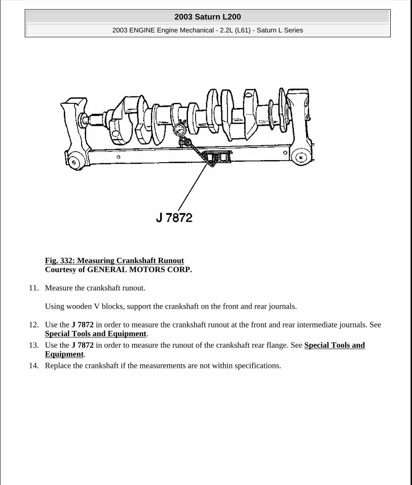
Fig. 332: Measuring Crankshaft Runout Courtesy of GENERAL MOTORS CORP.
11. Measure the crankshaft runout.
Using wooden V blocks, support the crankshaft on the front and rear journals.
12. Use the J 7872 in order to measure the crankshaft runout at the front and rear intermediate journals. See Special Tools and Equipment.
13. Use the J 7872 in order to measure the runout of the crankshaft rear flange. See Special Tools and Equipment.
14. Replace the crankshaft if the measurements are not within specifications.
2003 Saturn L200
2003 ENGINE Engine Mechanical - 2.2L (L61) - Saturn L Series
steve
Monday, May 09, 2011 12:52:06 PM Page 386 © 2006 Mitchell Repair Information Company, LLC.

Fig. 333: Identifying Crankshaft Bearing Craters Or Pockets Courtesy of GENERAL MOTORS CORP.
15. Inspect crankshaft bearings for craters or pockets. Flattened sections on the bearing halves also indicate fatigue.
2003 Saturn L200
2003 ENGINE Engine Mechanical - 2.2L (L61) - Saturn L Series
steve
Monday, May 09, 2011 12:52:06 PM Page 387 © 2006 Mitchell Repair Information Company, LLC.

Fig. 334: Identifying Connecting Rod Bearing Scoring Or Discoloration Courtesy of GENERAL MOTORS CORP.
16. Inspect the crankshaft bearings for excessive scoring or discoloration.
17. Inspect the crankshaft bearings for dirt or debris imbedded into the bearing material.
2003 Saturn L200
2003 ENGINE Engine Mechanical - 2.2L (L61) - Saturn L Series
steve
Monday, May 09, 2011 12:52:06 PM Page 388 © 2006 Mitchell Repair Information Company, LLC.

Fig. 335: Crankshaft Bearing Polished Sections (Improper Seating) Courtesy of GENERAL MOTORS CORP.
18. Inspect the crankshaft bearings for improper seating indicated by bright, polished sections of the bearing.
If the lower half of the bearing is worn or damaged, both upper and lower halves should be replaced.
Generally, if the lower half is suitable for use, the upper half should also be suitable for use.
PISTON AND CONNECTING ROD DISASSEMBLE
Tools Required
J 43654 Piston Pin Clip Installer. See Special Tools and Equipment.
2003 Saturn L200
2003 ENGINE Engine Mechanical - 2.2L (L61) - Saturn L Series
steve
Monday, May 09, 2011 12:52:06 PM Page 389 © 2006 Mitchell Repair Information Company, LLC.
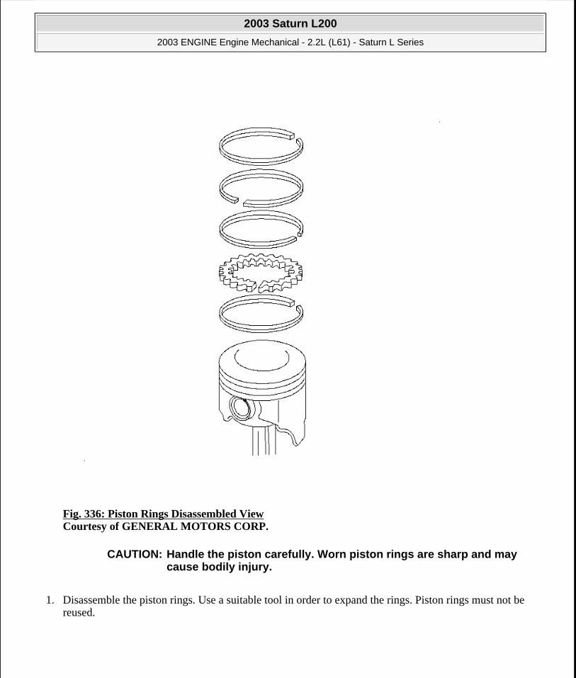
Fig. 336: Piston Rings Disassembled View Courtesy of GENERAL MOTORS CORP.
1. Disassemble the piston rings. Use a suitable tool in order to expand the rings. Piston rings must not be reused.
CAUTION: Handle the piston carefully. Worn piston rings are sharp and may cause bodily injury.
2003 Saturn L200
2003 ENGINE Engine Mechanical - 2.2L (L61) - Saturn L Series
steve
Monday, May 09, 2011 12:52:06 PM Page 390 © 2006 Mitchell Repair Information Company, LLC.

Fig. 337: Removing Piston Pin Retaining Ring Clips Courtesy of GENERAL MOTORS CORP.
2. Remove the piston pin retaining clips using the J 43654 . See Special Tools and Equipment.
2003 Saturn L200
2003 ENGINE Engine Mechanical - 2.2L (L61) - Saturn L Series
steve
Monday, May 09, 2011 12:52:06 PM Page 391 © 2006 Mitchell Repair Information Company, LLC.

Fig. 338: Removing Piston Pin Courtesy of GENERAL MOTORS CORP.
3. Remove the piston pin.
PISTON, CONNECTING ROD, AND BEARINGS CLEANING AND INSPECTION
Connecting Rod Measurement
2003 Saturn L200
2003 ENGINE Engine Mechanical - 2.2L (L61) - Saturn L Series
steve
Monday, May 09, 2011 12:52:06 PM Page 392 © 2006 Mitchell Repair Information Company, LLC.

Fig. 339: Cleaning Connecting Rods Courtesy of GENERAL MOTORS CORP.
1. Clean the connecting rods in solvent and dry with compressed air.
2. Inspect the connecting rods for the following:
Signs of being twisted, bent, nicked, or cracked
Scratches or abrasion on the rod bearing seating surface
2003 Saturn L200
2003 ENGINE Engine Mechanical - 2.2L (L61) - Saturn L Series
steve
Monday, May 09, 2011 12:52:06 PM Page 393 © 2006 Mitchell Repair Information Company, LLC.
3. If the connecting rod bores contain minor scratches or abrasions, clean the bores in a circular direction with a light emery paper. DO NOT scrape the rod or rod cap.
4. If the beam of the rod is scratched or has other damage replace the connecting rod.
5. Measure the piston pin to connecting rod bore using the following procedure:
1. Using an outside micrometer, take two measurements of the piston pin in the area of the connecting rod contact.
2. Using an inside micrometer, measure the connecting rod piston pin bore.
3. Subtract the piston pin diameter from the piston pin bore diameter.
4. The clearance should not be more than 0.021 mm (0.0008 in).
6. If there is excessive clearance, replace the piston pin.
7. If there is still excessive clearance, replace the connecting rod.
Piston Measurement
2003 Saturn L200
2003 ENGINE Engine Mechanical - 2.2L (L61) - Saturn L Series
steve
Monday, May 09, 2011 12:52:06 PM Page 394 © 2006 Mitchell Repair Information Company, LLC.
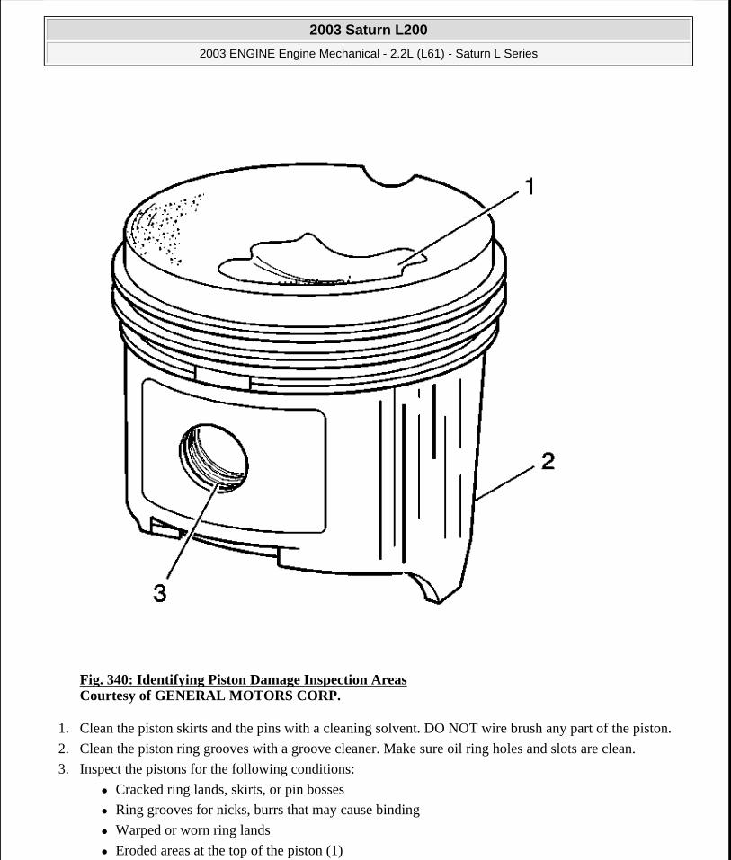
Fig. 340: Identifying Piston Damage Inspection Areas Courtesy of GENERAL MOTORS CORP.
1. Clean the piston skirts and the pins with a cleaning solvent. DO NOT wire brush any part of the piston.
2. Clean the piston ring grooves with a groove cleaner. Make sure oil ring holes and slots are clean.
3. Inspect the pistons for the following conditions:
Cracked ring lands, skirts, or pin bosses
Ring grooves for nicks, burrs that may cause binding
Warped or worn ring lands
Eroded areas at the top of the piston (1)
2003 Saturn L200
2003 ENGINE Engine Mechanical - 2.2L (L61) - Saturn L Series
steve
Monday, May 09, 2011 12:52:06 PM Page 395 © 2006 Mitchell Repair Information Company, LLC.

Scuffed or damaged skirts (2)
Worn piston pin bores (3)
4. Replace pistons that show any signs or damage or excessive wear.
5. Measure the piston pin bore to piston pin clearances using the following procedure:
1. Piston pin bores and pins must be free of varnish or scuffing.
2. Use an outside micrometer to measure the piston pin in the piston contact areas.
3. Using an inside micrometer, measure the piston pin bore.
4. Subtract the measurement of the piston pin bore from the piston pin. The clearance should be within 0.002-0.012 mm (0.00007-0.00047 in).
5. If the clearance is excessive, determine which component is out of specification.
2003 Saturn L200
2003 ENGINE Engine Mechanical - 2.2L (L61) - Saturn L Series
steve
Monday, May 09, 2011 12:52:06 PM Page 396 © 2006 Mitchell Repair Information Company, LLC.

Fig. 341: Measuring Piston Ring End Gap Courtesy of GENERAL MOTORS CORP.
6. Measure the piston ring end gap using the following procedure:
1. Place the piston ring in the area of the bore where the piston ring will travel (approximately 25 mm or 1 inch down from the deck surface). Be sure the ring is square with the cylinder bore by positioning the ring with the piston head.
2003 Saturn L200
2003 ENGINE Engine Mechanical - 2.2L (L61) - Saturn L Series
steve
Monday, May 09, 2011 12:52:06 PM Page 397 © 2006 Mitchell Repair Information Company, LLC.

2. Measure the end gap of the piston ring with feeler gages. Compare the measurements with those provided below:
The top compression ring end gap should be 0.20-0.40 mm (0.0060-0.015 in).
The second compression ring end gap should be 0.35-0.55 mm (0.0137-0.0216 in).
The oil ring end gap should be 0.25-0.76 mm (0.0098-0.029 in).
3. If the clearance exceeds the provided specifications, the piston rings must be replaced.
4. Repeat the procedure for all the piston rings.
Fig. 342: Measuring Piston Ring Side Clearance Courtesy of GENERAL MOTORS CORP.
7. Measure the piston ring side clearance using the following procedure:
1. Roll the piston ring entirely around the piston ring groove. If any binding is caused by a distorted piston ring, replace the ring.
2. With the piston ring on the piston, use feeler gages to check clearance at multiple locations.
3. The clearance between the surface of the top piston ring and the ring land should be no greater than 0.075 mm (0.0030 in).
4. If the clearance is greater than specifications, replace the piston ring.
5. If the new ring does not reduce the top ring side clearance to 0.075 mm (0.0030 in) or less, install a
2003 Saturn L200
2003 ENGINE Engine Mechanical - 2.2L (L61) - Saturn L Series
steve
Monday, May 09, 2011 12:52:06 PM Page 398 © 2006 Mitchell Repair Information Company, LLC.
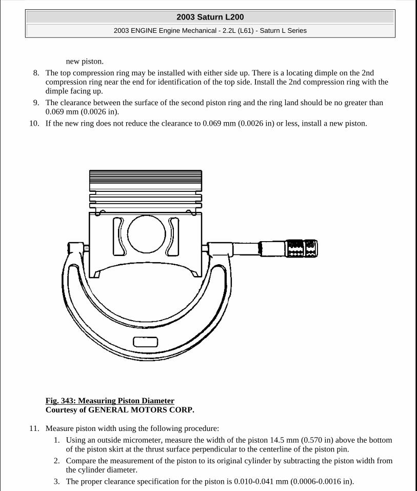
new piston.
8. The top compression ring may be installed with either side up. There is a locating dimple on the 2nd compression ring near the end for identification of the top side. Install the 2nd compression ring with the dimple facing up.
9. The clearance between the surface of the second piston ring and the ring land should be no greater than 0.069 mm (0.0026 in).
10. If the new ring does not reduce the clearance to 0.069 mm (0.0026 in) or less, install a new piston.
Fig. 343: Measuring Piston Diameter Courtesy of GENERAL MOTORS CORP.
11. Measure piston width using the following procedure:
1. Using an outside micrometer, measure the width of the piston 14.5 mm (0.570 in) above the bottom of the piston skirt at the thrust surface perpendicular to the centerline of the piston pin.
2. Compare the measurement of the piston to its original cylinder by subtracting the piston width from the cylinder diameter.
3. The proper clearance specification for the piston is 0.010-0.041 mm (0.0006-0.0016 in).
2003 Saturn L200
2003 ENGINE Engine Mechanical - 2.2L (L61) - Saturn L Series
steve
Monday, May 09, 2011 12:52:06 PM Page 399 © 2006 Mitchell Repair Information Company, LLC.

12. If the clearance obtained through measurement is greater than these specifications and the cylinder bores are within specification, replace the piston.
Piston Selection
Fig. 344: Measuring Cylinder Bore Courtesy of GENERAL MOTORS CORP.
2003 Saturn L200
2003 ENGINE Engine Mechanical - 2.2L (L61) - Saturn L Series
steve
Monday, May 09, 2011 12:52:06 PM Page 400 © 2006 Mitchell Repair Information Company, LLC.
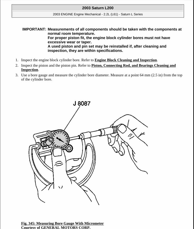
1. Inspect the engine block cylinder bore. Refer to Engine Block Cleaning and Inspection.
2. Inspect the piston and the piston pin. Refer to Piston, Connecting Rod, and Bearings Cleaning and Inspection.
3. Use a bore gauge and measure the cylinder bore diameter. Measure at a point 64 mm (2.5 in) from the top of the cylinder bore.
Fig. 345: Measuring Bore Gauge With Micrometer Courtesy of GENERAL MOTORS CORP.
IMPORTANT: Measurements of all components should be taken with the components at normal room temperature. For proper piston fit, the engine block cylinder bores must not have excessive wear or taper. A used piston and pin set may be reinstalled if, after cleaning and inspection, they are within specifications.
2003 Saturn L200
2003 ENGINE Engine Mechanical - 2.2L (L61) - Saturn L Series
steve
Monday, May 09, 2011 12:52:06 PM Page 401 © 2006 Mitchell Repair Information Company, LLC.

4. Measure the bore gauge with a micrometer and record the reading.
Fig. 346: Measuring Piston Diameter Courtesy of GENERAL MOTORS CORP.
5. With a micrometer or caliper at a right angle to the piston, measure the piston 14 mm (0.570 in) from the bottom of the skirt.
6. Subtract the piston diameter from the cylinder bore diameter in order to determine piston-to-bore clearance.
7. For proper piston-to-bore clearance. Refer to Engine Mechanical Specifications.
8. If the proper clearance cannot be obtained, select another piston and measure for the clearances.
9. If the proper fit cannot be obtained, hone the cylinder bore or replace the cylinder block.
10. When the piston-to-cylinder bore clearance is within specifications, mark the top of the piston using a permanent marker for installation to the proper cylinder. Refer to Separating Parts.
PISTON AND CONNECTING ROD ASSEMBLE
2003 Saturn L200
2003 ENGINE Engine Mechanical - 2.2L (L61) - Saturn L Series
steve
Monday, May 09, 2011 12:52:06 PM Page 402 © 2006 Mitchell Repair Information Company, LLC.

Tools Required
J 43654 Piston Pin Clip Installer. See Special Tools and Equipment.
Fig. 347: Assembling Connecting Rod & Piston Courtesy of GENERAL MOTORS CORP.
1. Assemble the connecting rod and the piston.
IMPORTANT: Install the piston onto the connecting rod with the arrow oriented toward the front of the engine.
2003 Saturn L200
2003 ENGINE Engine Mechanical - 2.2L (L61) - Saturn L Series
steve
Monday, May 09, 2011 12:52:06 PM Page 403 © 2006 Mitchell Repair Information Company, LLC.

Fig. 348: Installing Piston Ring Retainers Courtesy of GENERAL MOTORS CORP.
2. Use the following procedure in order to assemble the piston pin and the retainer:
1. Coat the piston pin with oil.
2. Using the J 43654 , install one side of one piston pin retainer into the retaining groove. See Special Tools and Equipment. Rotate the retainer until it is fully seated in the groove.
3. Install the connecting rod and the piston pin. Push the piston pin until it bottoms in the previously installed retainer.
NOTE: Install the piston pin retainers correctly in the retaining groove during assembly in order to avoid engine damage.
2003 Saturn L200
2003 ENGINE Engine Mechanical - 2.2L (L61) - Saturn L Series
steve
Monday, May 09, 2011 12:52:06 PM Page 404 © 2006 Mitchell Repair Information Company, LLC.

4. Install the second piston pin retainer using an insertion tool.
5. Ensure that the piston moves freely.
Fig. 349: Piston Ring Disassembled View Courtesy of GENERAL MOTORS CORP.
3. Install the following components of the oil control ring assembly (bottom ring):
1. Expander
2. Lower oil control ring
NOTE: Use a piston ring expander to install the piston rings. The rings may be damaged if expanded more than necessary.
2003 Saturn L200
2003 ENGINE Engine Mechanical - 2.2L (L61) - Saturn L Series
steve
Monday, May 09, 2011 12:52:06 PM Page 405 © 2006 Mitchell Repair Information Company, LLC.
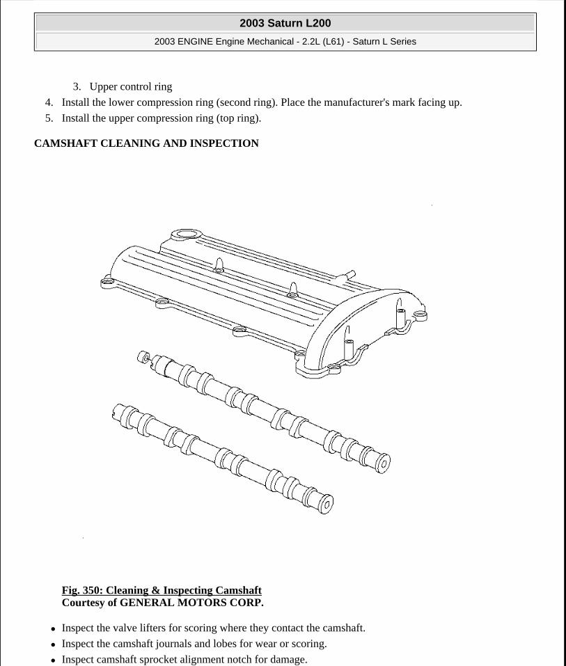
3. Upper control ring
4. Install the lower compression ring (second ring). Place the manufacturer's mark facing up.
5. Install the upper compression ring (top ring).
CAMSHAFT CLEANING AND INSPECTION
Fig. 350: Cleaning & Inspecting Camshaft Courtesy of GENERAL MOTORS CORP.
Inspect the valve lifters for scoring where they contact the camshaft.
Inspect the camshaft journals and lobes for wear or scoring.
Inspect camshaft sprocket alignment notch for damage.
2003 Saturn L200
2003 ENGINE Engine Mechanical - 2.2L (L61) - Saturn L Series
steve
Monday, May 09, 2011 12:52:06 PM Page 406 © 2006 Mitchell Repair Information Company, LLC.
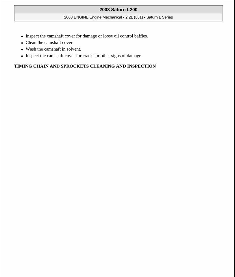
Inspect the camshaft cover for damage or loose oil control baffles.
Clean the camshaft cover.
Wash the camshaft in solvent.
Inspect the camshaft cover for cracks or other signs of damage.
TIMING CHAIN AND SPROCKETS CLEANING AND INSPECTION
2003 Saturn L200
2003 ENGINE Engine Mechanical - 2.2L (L61) - Saturn L Series
steve
Monday, May 09, 2011 12:52:06 PM Page 407 © 2006 Mitchell Repair Information Company, LLC.

Fig. 351: Exploded View Of Timing Chain & Sprocket Assemblies Courtesy of GENERAL MOTORS CORP.
1. Inspect the timing chain guides for cracking or wear.
2. Replace the timing chain guides if wear exceeds 1.12 mm (0.045 in) depth on the chain guide surface.
3. Inspect the timing chain tensioner shoe for wear.
2003 Saturn L200
2003 ENGINE Engine Mechanical - 2.2L (L61) - Saturn L Series
steve
Monday, May 09, 2011 12:52:06 PM Page 408 © 2006 Mitchell Repair Information Company, LLC.
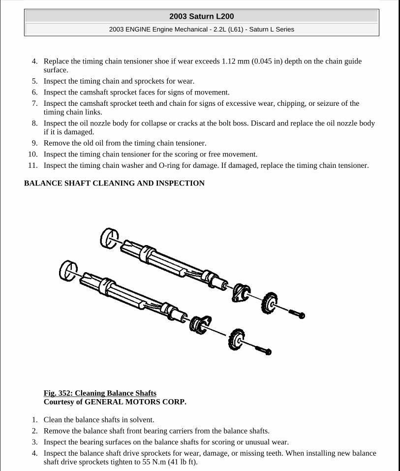
4. Replace the timing chain tensioner shoe if wear exceeds 1.12 mm (0.045 in) depth on the chain guide surface.
5. Inspect the timing chain and sprockets for wear.
6. Inspect the camshaft sprocket faces for signs of movement.
7. Inspect the camshaft sprocket teeth and chain for signs of excessive wear, chipping, or seizure of the timing chain links.
8. Inspect the oil nozzle body for collapse or cracks at the bolt boss. Discard and replace the oil nozzle body if it is damaged.
9. Remove the old oil from the timing chain tensioner.
10. Inspect the timing chain tensioner for the scoring or free movement.
11. Inspect the timing chain washer and O-ring for damage. If damaged, replace the timing chain tensioner.
BALANCE SHAFT CLEANING AND INSPECTION
Fig. 352: Cleaning Balance Shafts Courtesy of GENERAL MOTORS CORP.
1. Clean the balance shafts in solvent.
2. Remove the balance shaft front bearing carriers from the balance shafts.
3. Inspect the bearing surfaces on the balance shafts for scoring or unusual wear.
4. Inspect the balance shaft drive sprockets for wear, damage, or missing teeth. When installing new balance shaft drive sprockets tighten to 55 N.m (41 lb ft).
2003 Saturn L200
2003 ENGINE Engine Mechanical - 2.2L (L61) - Saturn L Series
steve
Monday, May 09, 2011 12:52:06 PM Page 409 © 2006 Mitchell Repair Information Company, LLC.

5. Measure the rear bearing journals on the balance shafts, the journals should be 36.723-36.743 mm (1.4458-1.4466 in) in diameter.
6. Measure the front bearing journals on the balance shafts, the front bearing journals should be 20.020-20.000 mm (0.7881-0.7874 in) in diameter.
7. When the balance shafts have been installed in the engine block, check for smooth rotation, sticking, binding, or roughness.
BALANCE SHAFT DRIVE CHAIN AND SPROCKETS CLEANING AND INSPECTION
Fig. 353: Exploded View Of Balance Shaft Drive Chain & Sprockets Courtesy of GENERAL MOTORS CORP.
1. Inspect the balance shaft drive chain guides for cracking or wear.
2. Replace the balance shaft drive chain guides if wear exceeds 1.12 mm (0.045 in) depth on the chain guide surface.
3. Inspect the balance shaft drive chain tensioner guide shoe for wear.
2003 Saturn L200
2003 ENGINE Engine Mechanical - 2.2L (L61) - Saturn L Series
steve
Monday, May 09, 2011 12:52:06 PM Page 410 © 2006 Mitchell Repair Information Company, LLC.

Replace the balance shaft drive chain tensioner guide shoe if wear exceeds 1.12 mm (0.045 in) depth on the chain guide surface.
4. Inspect the balance shaft drive chain and sprockets for wear.
5. Inspect the crankshaft sprocket faces for signs of movement.
6. Inspect the alignment notch in the balance shaft for cracking or damage.
7. Inspect the water pump, crankshaft, and balance shaft sprocket teeth and chain for signs of excessive wear, chipping, or seizure of the balance shaft drive chain links.
8. Inspect the timing chain tensioner for damage or wear.
CYLINDER HEAD DISASSEMBLE
Tools Required
J 8062 Valve Spring Compressor. See Special Tools and Equipment.
J 36017 Valve Guide Seal Remover. See Special Tools and Equipment.
J 43963 Valve Spring Compressor Adapter. See Special Tools and Equipment.
2003 Saturn L200
2003 ENGINE Engine Mechanical - 2.2L (L61) - Saturn L Series
steve
Monday, May 09, 2011 12:52:06 PM Page 411 © 2006 Mitchell Repair Information Company, LLC.
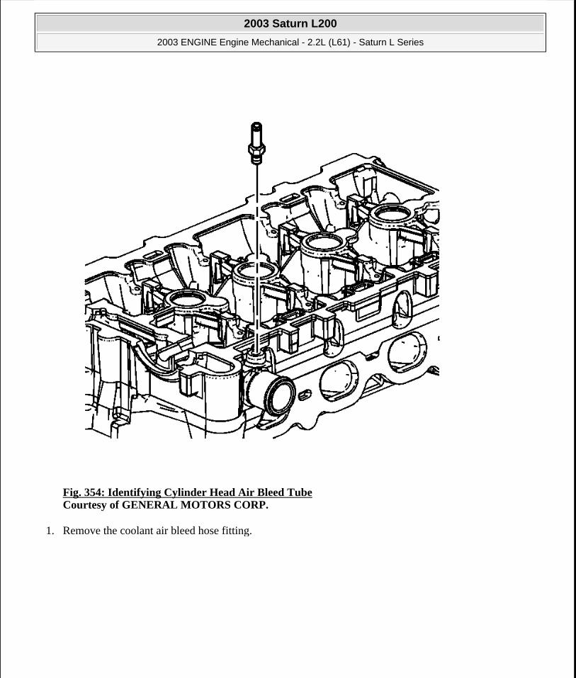
Fig. 354: Identifying Cylinder Head Air Bleed Tube Courtesy of GENERAL MOTORS CORP.
1. Remove the coolant air bleed hose fitting.
2003 Saturn L200
2003 ENGINE Engine Mechanical - 2.2L (L61) - Saturn L Series
steve
Monday, May 09, 2011 12:52:06 PM Page 412 © 2006 Mitchell Repair Information Company, LLC.

Fig. 355: Identifying Valve Spring Retainers Courtesy of GENERAL MOTORS CORP.
2. Using the J 8062 and the J 43963 , compress the valve spring. See Special Tools and Equipment.
3. Remove the valve keys.
4. Slowly release the J 8062 and the J 43963 from the valve spring assembly. See Special Tools and Equipment.
5. Remove the retainer.
IMPORTANT: Ensure that the valve train components are kept together and identified in order for proper re-installation in their original position.
2003 Saturn L200
2003 ENGINE Engine Mechanical - 2.2L (L61) - Saturn L Series
steve
Monday, May 09, 2011 12:52:06 PM Page 413 © 2006 Mitchell Repair Information Company, LLC.

Fig. 356: View Of Valve Springs Courtesy of GENERAL MOTORS CORP.
6. Remove the spring.
2003 Saturn L200
2003 ENGINE Engine Mechanical - 2.2L (L61) - Saturn L Series
steve
Monday, May 09, 2011 12:52:06 PM Page 414 © 2006 Mitchell Repair Information Company, LLC.

Fig. 357: Identifying Valve Seals Courtesy of GENERAL MOTORS CORP.
7. Remove the valve seal. Use the J 36017 . See Special Tools and Equipment. Do not reuse.
NOTE: Do not damage the valve guide. Remove any burrs that have formed at the key groove by chamfering the valve stem with an oil stone or a file.
2003 Saturn L200
2003 ENGINE Engine Mechanical - 2.2L (L61) - Saturn L Series
steve
Monday, May 09, 2011 12:52:06 PM Page 415 © 2006 Mitchell Repair Information Company, LLC.
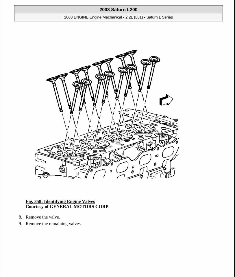
Fig. 358: Identifying Engine Valves Courtesy of GENERAL MOTORS CORP.
8. Remove the valve.
9. Remove the remaining valves.
2003 Saturn L200
2003 ENGINE Engine Mechanical - 2.2L (L61) - Saturn L Series
steve
Monday, May 09, 2011 12:52:06 PM Page 416 © 2006 Mitchell Repair Information Company, LLC.

Fig. 359: View Of Cylinder Head Plugs Courtesy of GENERAL MOTORS CORP.
10. Remove the cylinder head plugs.
CYLINDER HEAD CLEANING AND INSPECTION
Valve Cleaning and Inspection
2003 Saturn L200
2003 ENGINE Engine Mechanical - 2.2L (L61) - Saturn L Series
steve
Monday, May 09, 2011 12:52:06 PM Page 417 © 2006 Mitchell Repair Information Company, LLC.

Fig. 360: Identifying Inspection Points For Valves Damage Courtesy of GENERAL MOTORS CORP.
1. Clean the valves of carbon, oil and varnish. Carbon can be removed with a wire brush, varnish can be removed by soaking in Parts Immersion Solvent, or equivalent.
2. Clean the valve guides.
3. Inspect the valve stem for wear (4).
IMPORTANT: Do not scratch the valve stem with the wire brush.
2003 Saturn L200
2003 ENGINE Engine Mechanical - 2.2L (L61) - Saturn L Series
steve
Monday, May 09, 2011 12:52:06 PM Page 418 © 2006 Mitchell Repair Information Company, LLC.

4. Inspect the valve keeper groove for chipping or wear (5). Replace the valve if chipped or worn.
5. Inspect the valve face for burning or cracking (1). If pieces are broken off, inspect the corresponding piston and cylinder head area for damage.
6. Inspect the valve stem for burrs and scratches. Burrs and minor scratches may be removed with an oil stone.
7. Inspect the valve stem for straightness and the valve head for bending or distortion (3) using V blocks. Bent or distorted valves must be replaced.
8. Clean the deposits from the valve face. Inspect the valve face for grooving.
9. Replace the valve if the face is grooved. Valve faces cannot be machined. If worn, or damaged, the valves must be replaced.
10. The valves may be lightly lapped to the valve seats.
Cylinder Head and Gasket Surface Cleaning and Inspection
Fig. 361: Identifying Spark Plugs
2003 Saturn L200
2003 ENGINE Engine Mechanical - 2.2L (L61) - Saturn L Series
steve
Monday, May 09, 2011 12:52:06 PM Page 419 © 2006 Mitchell Repair Information Company, LLC.

Courtesy of GENERAL MOTORS CORP.
1. Remove the spark plugs.
2. Inspect the cylinder head gasket and mating surfaces for leaks, corrosion and blow-by. If the gasket has failed, use the following faults to determine the cause:
Improper installation
Loose or warped cylinder head
Missing, off location or not fully seated dowel pins
Corrosion in the seal area around the coolant passages
Chips or debris in the cylinder head bolt holes
Bolt holes in the cylinder block not drilled or tapped deep enough
Other
Fig. 362: Inspecting Cylinder Head Gasket Surface Courtesy of GENERAL MOTORS CORP.
3. Inspect the cylinder head gasket surface.
2003 Saturn L200
2003 ENGINE Engine Mechanical - 2.2L (L61) - Saturn L Series
steve
Monday, May 09, 2011 12:52:06 PM Page 420 © 2006 Mitchell Repair Information Company, LLC.
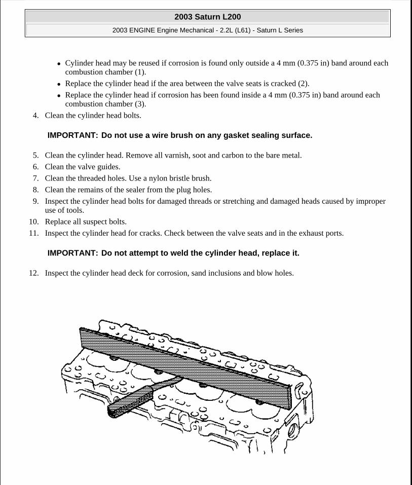
Cylinder head may be reused if corrosion is found only outside a 4 mm (0.375 in) band around each combustion chamber (1).
Replace the cylinder head if the area between the valve seats is cracked (2).
Replace the cylinder head if corrosion has been found inside a 4 mm (0.375 in) band around each combustion chamber (3).
4. Clean the cylinder head bolts.
5. Clean the cylinder head. Remove all varnish, soot and carbon to the bare metal.
6. Clean the valve guides.
7. Clean the threaded holes. Use a nylon bristle brush.
8. Clean the remains of the sealer from the plug holes.
9. Inspect the cylinder head bolts for damaged threads or stretching and damaged heads caused by improper use of tools.
10. Replace all suspect bolts.
11. Inspect the cylinder head for cracks. Check between the valve seats and in the exhaust ports.
12. Inspect the cylinder head deck for corrosion, sand inclusions and blow holes.
IMPORTANT: Do not use a wire brush on any gasket sealing surface.
IMPORTANT: Do not attempt to weld the cylinder head, replace it.
2003 Saturn L200
2003 ENGINE Engine Mechanical - 2.2L (L61) - Saturn L Series
steve
Monday, May 09, 2011 12:52:06 PM Page 421 © 2006 Mitchell Repair Information Company, LLC.

Fig. 363: Checking Cylinder Head Deck SurfaceCourtesy of GENERAL MOTORS CORP.
13. Inspect the cylinder head deck surface for flatness. Refer to Engine Mechanical Specifications.
14. Inspect the cylinder head intake and exhaust manifold mating surface for flatness.
15. Inspect all the threaded holes for damage. Threads may be reconditioned with thread inserts.
16. Inspect the sealing surfaces.
Fig. 364: View Of Cylinder Head Plugs Courtesy of GENERAL MOTORS CORP.
2003 Saturn L200
2003 ENGINE Engine Mechanical - 2.2L (L61) - Saturn L Series
steve
Monday, May 09, 2011 12:52:06 PM Page 422 © 2006 Mitchell Repair Information Company, LLC.

17. Inspect the cylinder head plugs.
CYLINDER HEAD ASSEMBLE
Tools Required
J 8062 Valve Spring Compressor. See Special Tools and Equipment.
J 9666 Valve Spring Tester. See Special Tools and Equipment.
J 43963 Valve Spring Compressor Adapter. See Special Tools and Equipment.
Fig. 365: View Of Cylinder Head Plugs
2003 Saturn L200
2003 ENGINE Engine Mechanical - 2.2L (L61) - Saturn L Series
steve
Monday, May 09, 2011 12:52:06 PM Page 423 © 2006 Mitchell Repair Information Company, LLC.

Courtesy of GENERAL MOTORS CORP.
1. Install NEW cylinder head plugs. Coat the plugs with threadlocker P/N 21485277, or equivalent.
Fig. 366: Inspecting Valve Spring For Squareness Courtesy of GENERAL MOTORS CORP.
2. Inspect the valve springs. Refer to Engine Mechanical Specifications for the tolerances.
3. Look for the following conditions when inspecting the valve springs:
Expanded height
Unparallel spring ends
Spring tension using J 9666
NOTE: In order to avoid damage, install the spark plugs after the cylinder head has been installed on the engine.
2003 Saturn L200
2003 ENGINE Engine Mechanical - 2.2L (L61) - Saturn L Series
steve
Monday, May 09, 2011 12:52:06 PM Page 424 © 2006 Mitchell Repair Information Company, LLC.
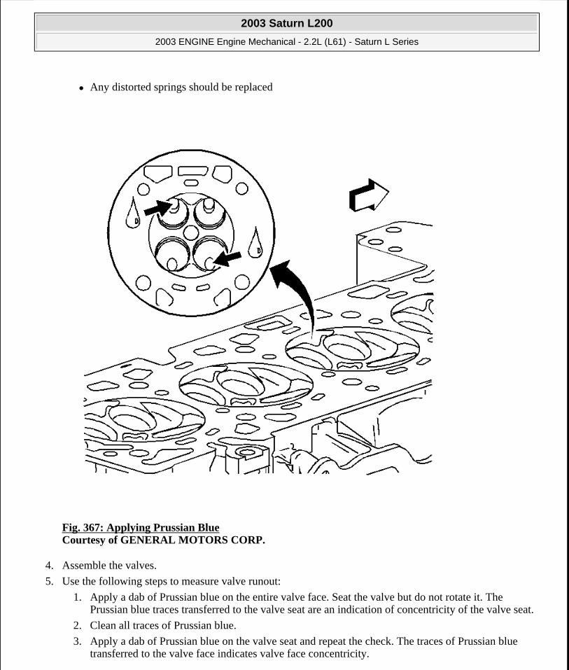
Any distorted springs should be replaced
Fig. 367: Applying Prussian Blue Courtesy of GENERAL MOTORS CORP.
4. Assemble the valves.
5. Use the following steps to measure valve runout:
1. Apply a dab of Prussian blue on the entire valve face. Seat the valve but do not rotate it. The Prussian blue traces transferred to the valve seat are an indication of concentricity of the valve seat.
2. Clean all traces of Prussian blue.
3. Apply a dab of Prussian blue on the valve seat and repeat the check. The traces of Prussian blue transferred to the valve face indicates valve face concentricity.
2003 Saturn L200
2003 ENGINE Engine Mechanical - 2.2L (L61) - Saturn L Series
steve
Monday, May 09, 2011 12:52:06 PM Page 425 © 2006 Mitchell Repair Information Company, LLC.
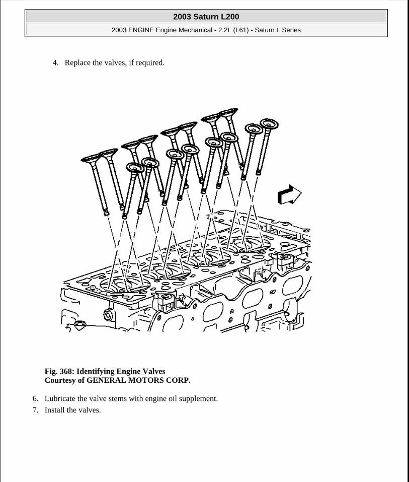
4. Replace the valves, if required.
Fig. 368: Identifying Engine Valves Courtesy of GENERAL MOTORS CORP.
6. Lubricate the valve stems with engine oil supplement.
7. Install the valves.
2003 Saturn L200
2003 ENGINE Engine Mechanical - 2.2L (L61) - Saturn L Series
steve
Monday, May 09, 2011 12:52:06 PM Page 426 © 2006 Mitchell Repair Information Company, LLC.

Fig. 369: Identifying Valve Seals Courtesy of GENERAL MOTORS CORP.
8. Install the new valve seals. Fully seat the seals on the valve guides.
2003 Saturn L200
2003 ENGINE Engine Mechanical - 2.2L (L61) - Saturn L Series
steve
Monday, May 09, 2011 12:52:06 PM Page 427 © 2006 Mitchell Repair Information Company, LLC.
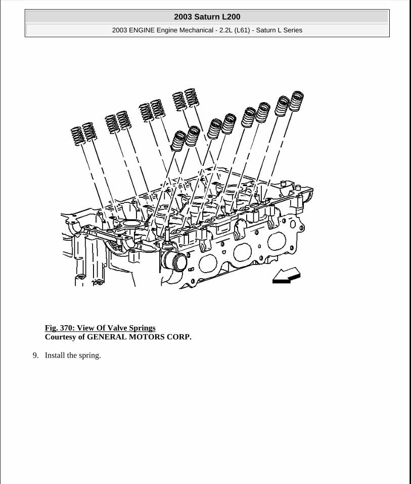
Fig. 370: View Of Valve Springs Courtesy of GENERAL MOTORS CORP.
9. Install the spring.
2003 Saturn L200
2003 ENGINE Engine Mechanical - 2.2L (L61) - Saturn L Series
steve
Monday, May 09, 2011 12:52:07 PM Page 428 © 2006 Mitchell Repair Information Company, LLC.

Fig. 371: Identifying Valve Spring Retainers Courtesy of GENERAL MOTORS CORP.
10. Install the retainer.
11. Using the J 8062 and the J 43963 , compress the valve spring. See Special Tools and Equipment.
12. Install the valve keys.
13. Slowly release the J 8062 and the J 43963 from the valve/spring assembly. See Special Tools and Equipment.
14. Inspect for proper valve key seating.
2003 Saturn L200
2003 ENGINE Engine Mechanical - 2.2L (L61) - Saturn L Series
steve
Monday, May 09, 2011 12:52:07 PM Page 429 © 2006 Mitchell Repair Information Company, LLC.
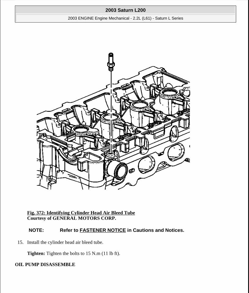
Fig. 372: Identifying Cylinder Head Air Bleed Tube Courtesy of GENERAL MOTORS CORP.
15. Install the cylinder head air bleed tube.
Tighten: Tighten the bolts to 15 N.m (11 lb ft).
OIL PUMP DISASSEMBLE
NOTE: Refer to FASTENER NOTICE in Cautions and Notices.
2003 Saturn L200
2003 ENGINE Engine Mechanical - 2.2L (L61) - Saturn L Series
steve
Monday, May 09, 2011 12:52:07 PM Page 430 © 2006 Mitchell Repair Information Company, LLC.

Fig. 373: Identifying Pressure Relief Valve Courtesy of GENERAL MOTORS CORP.
1. Disassemble the pressure relief valve.
2003 Saturn L200
2003 ENGINE Engine Mechanical - 2.2L (L61) - Saturn L Series
steve
Monday, May 09, 2011 12:52:07 PM Page 431 © 2006 Mitchell Repair Information Company, LLC.

Fig. 374: Removing Gerotor Cover & Bolts Courtesy of GENERAL MOTORS CORP.
2. Remove the gerotor cover and bolts.
3. Clean all parts in cleaning solvent. Remove the varnish, sludge, and dirt.
4. Inspect the oil pump gears for wear and scoring. Ensure all components are within specifications.
5. Replace the front cover and oil pump assembly if out of specification or damaged.
OIL PUMP CLEANING AND INSPECTION
Tools Required
2003 Saturn L200
2003 ENGINE Engine Mechanical - 2.2L (L61) - Saturn L Series
steve
Monday, May 09, 2011 12:52:07 PM Page 432 © 2006 Mitchell Repair Information Company, LLC.
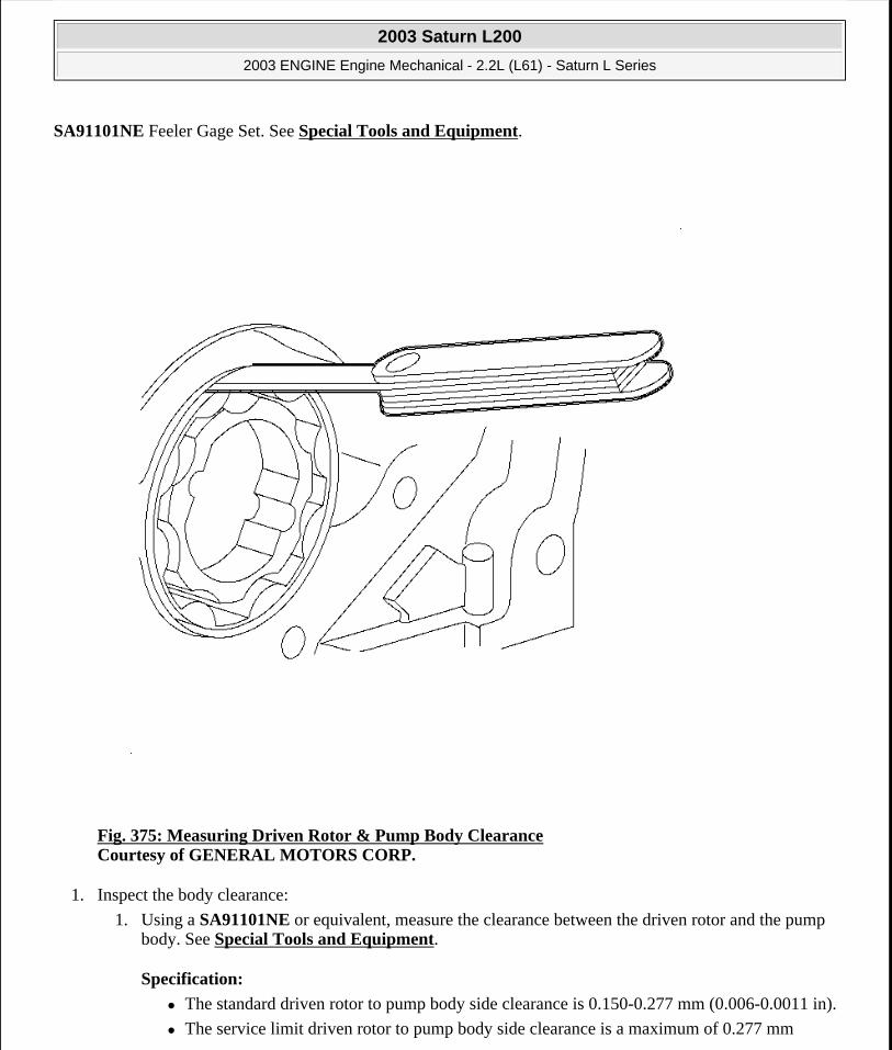
SA91101NE Feeler Gage Set. See Special Tools and Equipment.
Fig. 375: Measuring Driven Rotor & Pump Body Clearance Courtesy of GENERAL MOTORS CORP.
1. Inspect the body clearance:
1. Using a SA91101NE or equivalent, measure the clearance between the driven rotor and the pump body. See Special Tools and Equipment.
Specification:
The standard driven rotor to pump body side clearance is 0.150-0.277 mm (0.006-0.0011 in).
The service limit driven rotor to pump body side clearance is a maximum of 0.277 mm
2003 Saturn L200
2003 ENGINE Engine Mechanical - 2.2L (L61) - Saturn L Series
steve
Monday, May 09, 2011 12:52:07 PM Page 433 © 2006 Mitchell Repair Information Company, LLC.

(0.011 in).
2. If the clearance is greater than the service limit, replace the oil pump assembly.
Fig. 376: Measuring Clearance Between Both Rotor Tips Courtesy of GENERAL MOTORS CORP.
2. Inspect the tip clearance:
1. Using a SA91101NE or equivalent, measure the clearance between both rotor tips. See Special Tools and Equipment.
Specification: The service limit rotor tip clearance is a maximum of 0.150 mm (0.006 in).
2003 Saturn L200
2003 ENGINE Engine Mechanical - 2.2L (L61) - Saturn L Series
steve
Monday, May 09, 2011 12:52:07 PM Page 434 © 2006 Mitchell Repair Information Company, LLC.

2. If the clearance is greater than the service limit, replace the oil pump assembly.
Fig. 377: Measuring Driven Rotors & Oil Pump Cover Plate Clearance Courtesy of GENERAL MOTORS CORP.
3. Inspect the end-to-end clearance:
1. Using a SA91101NE , Plastigae®, or equivalent, measure the clearance between the side of the drive and the driven rotors and the oil pump cover plate. See Special Tools and Equipment.
Specification:
The standard rotor to cover side clearance is 0.040-0.125 mm (0.0016-0.0049 in).
The service limit rotor to cover side clearance maximum is 0.08 mm (0.003 in).
2003 Saturn L200
2003 ENGINE Engine Mechanical - 2.2L (L61) - Saturn L Series
steve
Monday, May 09, 2011 12:52:07 PM Page 435 © 2006 Mitchell Repair Information Company, LLC.

2. If the clearance is greater than the service limit, replace the oil pump assembly.
OIL PUMP ASSEMBLE
Fig. 378: Exploded View of Gerotor Gears Courtesy of GENERAL MOTORS CORP.
1. Install the gear with the groove in the gear aligning with the race in the front cover.
NOTE: Front cover damage and engine damage will result if the gerotor gears are not properly installed into the front cover.
2003 Saturn L200
2003 ENGINE Engine Mechanical - 2.2L (L61) - Saturn L Series
steve
Monday, May 09, 2011 12:52:07 PM Page 436 © 2006 Mitchell Repair Information Company, LLC.

2. Install the gerotor cover and bolts.
Tighten: Tighten the oil pump gerotor cover bolts to 6 N.m (53 lb in).
Fig. 379: Identifying Pressure Relief Valve Piston Courtesy of GENERAL MOTORS CORP.
3. Install the pressure relief valve piston.
4. Install the pressure relief valve spring.
5. Install the pressure relief valve plug.
NOTE: Refer to FASTENER NOTICE in Cautions and Notices.
2003 Saturn L200
2003 ENGINE Engine Mechanical - 2.2L (L61) - Saturn L Series
steve
Monday, May 09, 2011 12:52:07 PM Page 437 © 2006 Mitchell Repair Information Company, LLC.

Tighten: Tighten the oil pump pressure relief valve plug to 40 N.m (30 lb ft).
INTAKE MANIFOLD CLEANING AND INSPECTION
Fig. 380: Cleaning & Inspecting Intake Manifold Courtesy of GENERAL MOTORS CORP.
1. Clean the intake manifold mating surfaces.
2. Inspect the intake manifold for damage.
3. Inspect the intake manifold for cracks near the compression limiters.
4. Inspect the crankcase ventilation passages in the intake manifold face for blockage and clean as necessary.
2003 Saturn L200
2003 ENGINE Engine Mechanical - 2.2L (L61) - Saturn L Series
steve
Monday, May 09, 2011 12:52:07 PM Page 438 © 2006 Mitchell Repair Information Company, LLC.

5. Replace the intake manifold as necessary.
EXHAUST MANIFOLD CLEANING AND INSPECTION
Fig. 381: Inspecting Exhaust Manifold Courtesy of GENERAL MOTORS CORP.
2003 Saturn L200
2003 ENGINE Engine Mechanical - 2.2L (L61) - Saturn L Series
steve
Monday, May 09, 2011 12:52:07 PM Page 439 © 2006 Mitchell Repair Information Company, LLC.
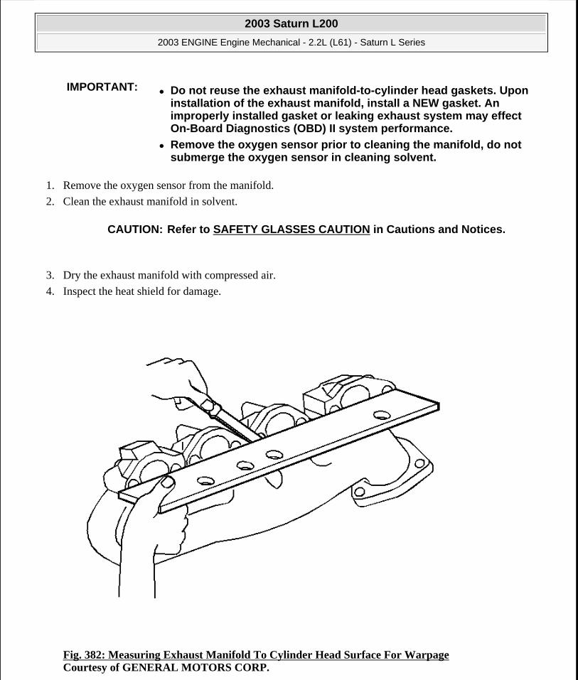
1. Remove the oxygen sensor from the manifold.
2. Clean the exhaust manifold in solvent.
3. Dry the exhaust manifold with compressed air.
4. Inspect the heat shield for damage.
Fig. 382: Measuring Exhaust Manifold To Cylinder Head Surface For Warpage Courtesy of GENERAL MOTORS CORP.
IMPORTANT: Do not reuse the exhaust manifold-to-cylinder head gaskets. Upon installation of the exhaust manifold, install a NEW gasket. An improperly installed gasket or leaking exhaust system may effect On-Board Diagnostics (OBD) II system performance.
Remove the oxygen sensor prior to cleaning the manifold, do not submerge the oxygen sensor in cleaning solvent.
CAUTION: Refer to SAFETY GLASSES CAUTION in Cautions and Notices.
2003 Saturn L200
2003 ENGINE Engine Mechanical - 2.2L (L61) - Saturn L Series
steve
Monday, May 09, 2011 12:52:07 PM Page 440 © 2006 Mitchell Repair Information Company, LLC.

5. Use a straight edge and a feeler gage and measure the exhaust manifold mounting face for warpage.
An exhaust manifold face with warpage in excess of 0.25 mm (0.010 in) may cause an exhaust leak and may effect OBD II system performance. Exhaust manifolds not within specifications must be replaced.
OIL PAN CLEANING AND INSPECTION
Fig. 383: Cleaning & Inspecting Oil Pan Courtesy of GENERAL MOTORS CORP.
2003 Saturn L200
2003 ENGINE Engine Mechanical - 2.2L (L61) - Saturn L Series
steve
Monday, May 09, 2011 12:52:07 PM Page 441 © 2006 Mitchell Repair Information Company, LLC.

1. Clean the oil pan mating surface.
2. Clean the oil pan. Remove all the sludge and the oil deposits.
3. Inspect the threads for the engine oil drain plug.
4. Inspect the oil pan for cracking near the pan rail and the transmission mounting points.
5. Inspect the oil pan for cracking resulting from impact or flying road debris.
6. Inspect the oil pan baffle and pickup screen.
7. Repair or replace the oil pan as necessary.
THREAD REPAIR - MAIN CAP BOLT HOLE
Thread Repair Kit
IMPORTANT: The oil pan baffle and pickup screen are not removable from the oil pan.
2003 Saturn L200
2003 ENGINE Engine Mechanical - 2.2L (L61) - Saturn L Series
steve
Monday, May 09, 2011 12:52:07 PM Page 442 © 2006 Mitchell Repair Information Company, LLC.
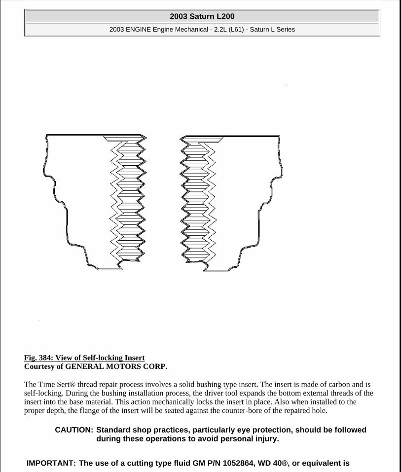
Fig. 384: View of Self-locking Insert Courtesy of GENERAL MOTORS CORP.
The Time Sert® thread repair process involves a solid bushing type insert. The insert is made of carbon and is self-locking. During the bushing installation process, the driver tool expands the bottom external threads of the insert into the base material. This action mechanically locks the insert in place. Also when installed to the proper depth, the flange of the insert will be seated against the counter-bore of the repaired hole.
CAUTION: Standard shop practices, particularly eye protection, should be followed during these operations to avoid personal injury.
IMPORTANT: The use of a cutting type fluid GM P/N 1052864, WD 40®, or equivalent is
2003 Saturn L200
2003 ENGINE Engine Mechanical - 2.2L (L61) - Saturn L Series
steve
Monday, May 09, 2011 12:52:07 PM Page 443 © 2006 Mitchell Repair Information Company, LLC.
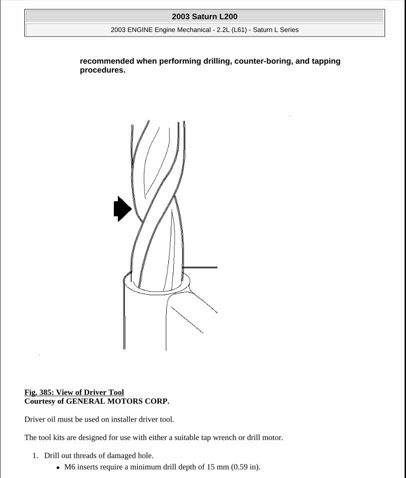
Fig. 385: View of Driver Tool Courtesy of GENERAL MOTORS CORP.
Driver oil must be used on installer driver tool.
The tool kits are designed for use with either a suitable tap wrench or drill motor.
1. Drill out threads of damaged hole.
M6 inserts require a minimum drill depth of 15 mm (0.59 in).
recommended when performing drilling, counter-boring, and tapping procedures.
2003 Saturn L200
2003 ENGINE Engine Mechanical - 2.2L (L61) - Saturn L Series
steve
Monday, May 09, 2011 12:52:07 PM Page 444 © 2006 Mitchell Repair Information Company, LLC.

M8 inserts require a minimum drill depth of 20 mm (0.79 in).
M10 inserts require a minimum drill depth of 23.5 mm (0.93 in).
2. Using compressed air, clean out any chips.
Fig. 386: Counter-boring Hole Courtesy of GENERAL MOTORS CORP.
3. Counter-bore hole to full depth permitted by tool.
4. Using compressed air, clean out any chips.
2003 Saturn L200
2003 ENGINE Engine Mechanical - 2.2L (L61) - Saturn L Series
steve
Monday, May 09, 2011 12:52:07 PM Page 445 © 2006 Mitchell Repair Information Company, LLC.

Fig. 387: Tapping Threads of Drilled Hole Courtesy of GENERAL MOTORS CORP.
5. Using a tap wrench, tap threads of drilled hole.
M6 inserts require a minimum tap depth of 15 mm (0.59 in).
M8 inserts require a minimum tap depth of 20 mm (0.79 in).
M10 inserts require a minimum tap depth of 23.5 mm (0.93 in).
6. Using compressed air, clean out any chips.
7. Spray cleaner GM P/N 12346139, P/N 12377981 or equivalent into holes.
8. Using compressed air, clean any cutting oil and chips out of drilled hole.
2003 Saturn L200
2003 ENGINE Engine Mechanical - 2.2L (L61) - Saturn L Series
steve
Monday, May 09, 2011 12:52:07 PM Page 446 © 2006 Mitchell Repair Information Company, LLC.
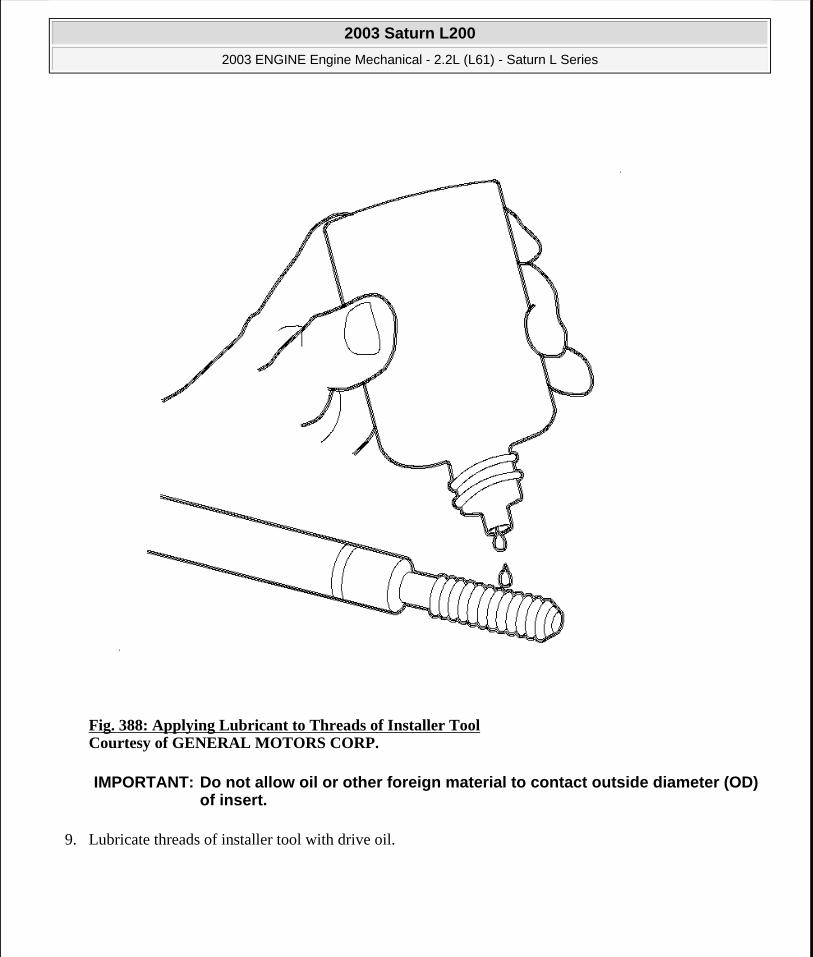
Fig. 388: Applying Lubricant to Threads of Installer Tool Courtesy of GENERAL MOTORS CORP.
9. Lubricate threads of installer tool with drive oil.
IMPORTANT: Do not allow oil or other foreign material to contact outside diameter (OD) of insert.
2003 Saturn L200
2003 ENGINE Engine Mechanical - 2.2L (L61) - Saturn L Series
steve
Monday, May 09, 2011 12:52:07 PM Page 447 © 2006 Mitchell Repair Information Company, LLC.

Fig. 389: Installing Insert to Installer Tool Courtesy of GENERAL MOTORS CORP.
10. Install insert onto installer tool.
2003 Saturn L200
2003 ENGINE Engine Mechanical - 2.2L (L61) - Saturn L Series
steve
Monday, May 09, 2011 12:52:07 PM Page 448 © 2006 Mitchell Repair Information Company, LLC.

Fig. 390: Applying High Strength Threadlock Red to Insert OD Threads Courtesy of GENERAL MOTORS CORP.
11. Apply High Strength Threadlock Red, J42385-109 or equivalent to insert OD threads.
2003 Saturn L200
2003 ENGINE Engine Mechanical - 2.2L (L61) - Saturn L Series
steve
Monday, May 09, 2011 12:52:07 PM Page 449 © 2006 Mitchell Repair Information Company, LLC.

Fig. 391: Installing Insert Courtesy of GENERAL MOTORS CORP.
12. Install insert into hole.
1. Install insert until flange of insert contacts counter-bored surface.
2. Continue to rotate installer tool through insert.
IMPORTANT: Installer tool will tighten up before screwing completely through insert. This is acceptable. You are forming bottom threads of insert and mechanically locking insert to base material threads.
2003 Saturn L200
2003 ENGINE Engine Mechanical - 2.2L (L61) - Saturn L Series
steve
Monday, May 09, 2011 12:52:07 PM Page 450 © 2006 Mitchell Repair Information Company, LLC.

Fig. 392: View of Properly Installed Insert Courtesy of GENERAL MOTORS CORP.
13. Inspect insert for proper installation into hole.
Main Cap Bolt Hole Thread
IMPORTANT: A properly installed insert will be either flush or slightly below flush with surface of base material.
2003 Saturn L200
2003 ENGINE Engine Mechanical - 2.2L (L61) - Saturn L Series
steve
Monday, May 09, 2011 12:52:07 PM Page 451 © 2006 Mitchell Repair Information Company, LLC.

Fig. 393: View of Main Cap Bolt Thread Repair Kit Courtesy of GENERAL MOTORS CORP.
1. The main cap bolt thread repair kit consists of the following items:
Drill (1)
Tap (2)
Installer (3)
Fixture Plate (4)
Long Bolts (5)
Short Bolts (6)
Alignment Pin (7)
2003 Saturn L200
2003 ENGINE Engine Mechanical - 2.2L (L61) - Saturn L Series
steve
Monday, May 09, 2011 12:52:07 PM Page 452 © 2006 Mitchell Repair Information Company, LLC.

Bushing (8)
Fig. 394: Identifying Alignment Doll Pins Courtesy of GENERAL MOTORS CORP.
2. Remove the alignment doll pins on holes 1-4 if necessary.
2003 Saturn L200
2003 ENGINE Engine Mechanical - 2.2L (L61) - Saturn L Series
steve
Monday, May 09, 2011 12:52:07 PM Page 453 © 2006 Mitchell Repair Information Company, LLC.
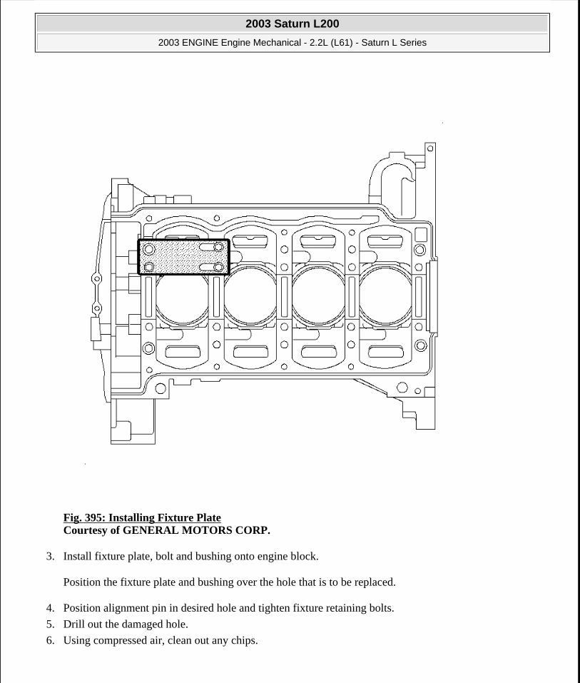
Fig. 395: Installing Fixture Plate Courtesy of GENERAL MOTORS CORP.
3. Install fixture plate, bolt and bushing onto engine block.
Position the fixture plate and bushing over the hole that is to be replaced.
4. Position alignment pin in desired hole and tighten fixture retaining bolts.
5. Drill out the damaged hole.
6. Using compressed air, clean out any chips.
2003 Saturn L200
2003 ENGINE Engine Mechanical - 2.2L (L61) - Saturn L Series
steve
Monday, May 09, 2011 12:52:07 PM Page 454 © 2006 Mitchell Repair Information Company, LLC.
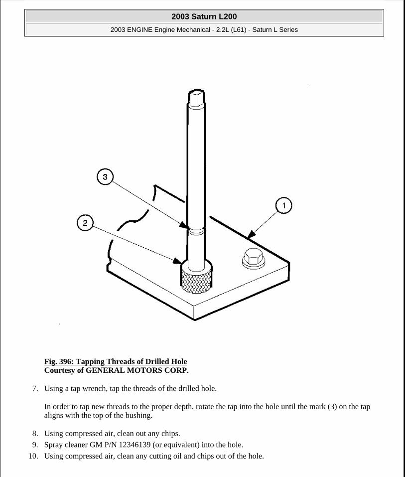
Fig. 396: Tapping Threads of Drilled Hole Courtesy of GENERAL MOTORS CORP.
7. Using a tap wrench, tap the threads of the drilled hole.
In order to tap new threads to the proper depth, rotate the tap into the hole until the mark (3) on the tap aligns with the top of the bushing.
8. Using compressed air, clean out any chips.
9. Spray cleaner GM P/N 12346139 (or equivalent) into the hole.
10. Using compressed air, clean any cutting oil and chips out of the hole.
2003 Saturn L200
2003 ENGINE Engine Mechanical - 2.2L (L61) - Saturn L Series
steve
Monday, May 09, 2011 12:52:07 PM Page 455 © 2006 Mitchell Repair Information Company, LLC.
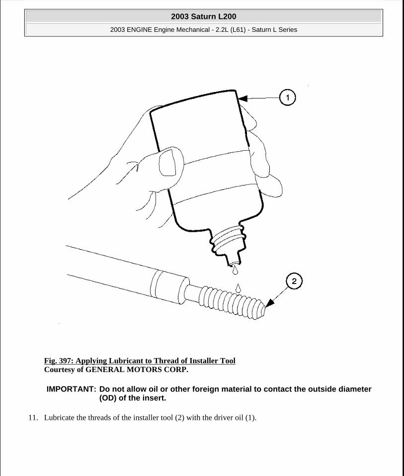
Fig. 397: Applying Lubricant to Thread of Installer Tool Courtesy of GENERAL MOTORS CORP.
11. Lubricate the threads of the installer tool (2) with the driver oil (1).
IMPORTANT: Do not allow oil or other foreign material to contact the outside diameter (OD) of the insert.
2003 Saturn L200
2003 ENGINE Engine Mechanical - 2.2L (L61) - Saturn L Series
steve
Monday, May 09, 2011 12:52:07 PM Page 456 © 2006 Mitchell Repair Information Company, LLC.

Fig. 398: Installing Insert to Driver Tool Courtesy of GENERAL MOTORS CORP.
12. Install the insert (2) onto the driver tool (1).
2003 Saturn L200
2003 ENGINE Engine Mechanical - 2.2L (L61) - Saturn L Series
steve
Monday, May 09, 2011 12:52:07 PM Page 457 © 2006 Mitchell Repair Information Company, LLC.

Fig. 399: Applying Threadlock To Insert Courtesy of GENERAL MOTORS CORP.
13. Apply High Strength Threadlocker® Red, J42385-109, (or equivalent) to the insert OD threads.
2003 Saturn L200
2003 ENGINE Engine Mechanical - 2.2L (L61) - Saturn L Series
steve
Monday, May 09, 2011 12:52:07 PM Page 458 © 2006 Mitchell Repair Information Company, LLC.

Fig. 400: Identifying Bushing, Fixture Plate, & Tool Courtesy of GENERAL MOTORS CORP.
14. Install the insert and driver through the bushing (2), fixture plate (1) and into the hole.
Rotate the driver tool until the mark on the tool (3) aligns with the top of the bushing (2).
The installer tool will tighten up before screwing completely through the insert. This is acceptable. You are forming the bottom threads of the insert and mechanically locking the insert to the base material threads.
IMPORTANT: The fixture plate and bushing remains installed onto the engine block during the insert installation procedure.
2003 Saturn L200
2003 ENGINE Engine Mechanical - 2.2L (L61) - Saturn L Series
steve
Monday, May 09, 2011 12:52:07 PM Page 459 © 2006 Mitchell Repair Information Company, LLC.

15. Remove the driver, bushing (2), fixture plate (1) and bolts.
Fig. 401: Installing Alignment Doll Pins Courtesy of GENERAL MOTORS CORP.
16. Install the alignment doll pins in holes 1-4 if necessary.
Cylinder Head Bolt Hole
2003 Saturn L200
2003 ENGINE Engine Mechanical - 2.2L (L61) - Saturn L Series
steve
Monday, May 09, 2011 12:52:07 PM Page 460 © 2006 Mitchell Repair Information Company, LLC.

2003 Saturn L200
2003 ENGINE Engine Mechanical - 2.2L (L61) - Saturn L Series
steve
Monday, May 09, 2011 12:52:07 PM Page 461 © 2006 Mitchell Repair Information Company, LLC.

Fig. 402: View of Cylinder Head Bolt Thread Repair KitCourtesy of GENERAL MOTORS CORP.
The cylinder head bolt thread repair kit consists of the following items:
Drill (1)
Tap (2)
Installer (3)
Alignment Pin (4)
Bushing (5)
Bolts (6)
Fixture Plate (7)
2003 Saturn L200
2003 ENGINE Engine Mechanical - 2.2L (L61) - Saturn L Series
steve
Monday, May 09, 2011 12:52:07 PM Page 462 © 2006 Mitchell Repair Information Company, LLC.

Fig. 403: Installing Fixture Plate, Bolts, & Bushing Courtesy of GENERAL MOTORS CORP.
Driver oil must be used on installer driver tool.
CAUTION: Standard shop practices, particularly eye protection, should be followed during these operations to avoid personal injury.
IMPORTANT: The use of a cutting type fluid GM P/N 1052864, WD 40® (or equivalent) is recommended when performing drilling, counter-boring, and tapping procedures.
2003 Saturn L200
2003 ENGINE Engine Mechanical - 2.2L (L61) - Saturn L Series
steve
Monday, May 09, 2011 12:52:07 PM Page 463 © 2006 Mitchell Repair Information Company, LLC.
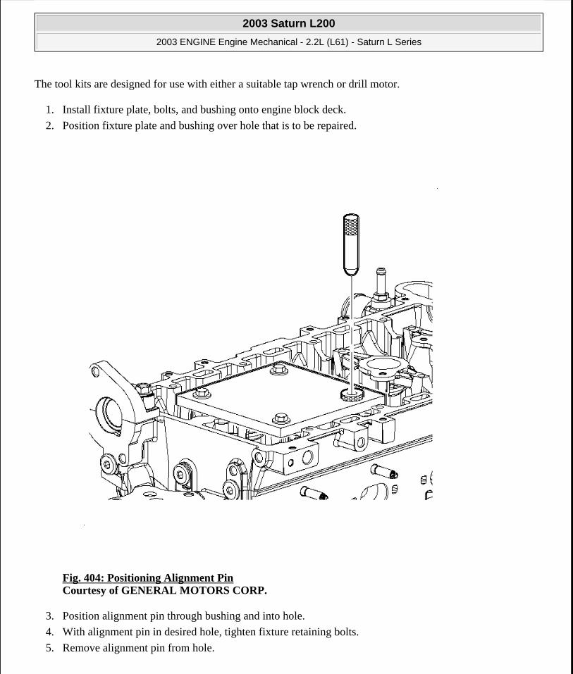
The tool kits are designed for use with either a suitable tap wrench or drill motor.
1. Install fixture plate, bolts, and bushing onto engine block deck.
2. Position fixture plate and bushing over hole that is to be repaired.
Fig. 404: Positioning Alignment Pin Courtesy of GENERAL MOTORS CORP.
3. Position alignment pin through bushing and into hole.
4. With alignment pin in desired hole, tighten fixture retaining bolts.
5. Remove alignment pin from hole.
2003 Saturn L200
2003 ENGINE Engine Mechanical - 2.2L (L61) - Saturn L Series
steve
Monday, May 09, 2011 12:52:07 PM Page 464 © 2006 Mitchell Repair Information Company, LLC.

Fig. 405: Drilling Out Threads of Damaged Hole Courtesy of GENERAL MOTORS CORP.
6. Install drill sleeve onto the drill if required.
7. Drill out threads of damaged hole.
8. Using compressed air, clean out any chips.
M6 inserts require a minimum drill depth of 15 mm (0.59 in).
M8 inserts require a minimum drill depth of 20 mm (0.79 in).
M10 inserts require a minimum drill depth of 23.5 mm (0.93 in).
IMPORTANT: During drilling process, it is necessary to repeatedly remove drill and clean chips from hole.
2003 Saturn L200
2003 ENGINE Engine Mechanical - 2.2L (L61) - Saturn L Series
steve
Monday, May 09, 2011 12:52:07 PM Page 465 © 2006 Mitchell Repair Information Company, LLC.

Fig. 406: Tapping Threads of Drilled Hole Courtesy of GENERAL MOTORS CORP.
9. Using tap wrench, tap threads of drilled hole.
2003 Saturn L200
2003 ENGINE Engine Mechanical - 2.2L (L61) - Saturn L Series
steve
Monday, May 09, 2011 12:52:07 PM Page 466 © 2006 Mitchell Repair Information Company, LLC.

Fig. 407: Aligning Mark of Tap With Top of Drill Bushing Courtesy of GENERAL MOTORS CORP.
10. Tap new threads to proper depth by turning tap into hole until mark on tap aligns with top of drill bushing.
11. Remove fixture plate, bushing, and bolts.
12. Using compressed air, clean out any chips.
13. Spray cleaner GM P/N 12346139, P/N 12377981 (or equivalent) into hole.
14. Using compressed air, clean any cutting oil and chips out of hole.
2003 Saturn L200
2003 ENGINE Engine Mechanical - 2.2L (L61) - Saturn L Series
steve
Monday, May 09, 2011 12:52:07 PM Page 467 © 2006 Mitchell Repair Information Company, LLC.

Fig. 408: Applying Lubricant to Threads of Installer Tools Courtesy of GENERAL MOTORS CORP.
15. Lubricate threads of installer tool with driver oil.
IMPORTANT: Do not allow oil or other foreign material to contact outside diameter (OD) of insert.
2003 Saturn L200
2003 ENGINE Engine Mechanical - 2.2L (L61) - Saturn L Series
steve
Monday, May 09, 2011 12:52:07 PM Page 468 © 2006 Mitchell Repair Information Company, LLC.

Fig. 409: Installing Insert to Driver Tool Courtesy of GENERAL MOTORS CORP.
16. Install the insert (2) onto driver tool (1).
2003 Saturn L200
2003 ENGINE Engine Mechanical - 2.2L (L61) - Saturn L Series
steve
Monday, May 09, 2011 12:52:07 PM Page 469 © 2006 Mitchell Repair Information Company, LLC.

Fig. 410: Apply High Strength Threadlock Red To Insert Of Threads Courtesy of GENERAL MOTORS CORP.
17. Apply High Strength Threadlock Red, J42385-109 (or equivalent) to insert OD threads.
2003 Saturn L200
2003 ENGINE Engine Mechanical - 2.2L (L61) - Saturn L Series
steve
Monday, May 09, 2011 12:52:07 PM Page 470 © 2006 Mitchell Repair Information Company, LLC.

Fig. 411: Installing Insert & Driver into Hole Courtesy of GENERAL MOTORS CORP.
18. Install insert and driver into hole.
19. Rotate driver tool until mark on tool aligns with deck surface of engine block.
SERVICE PRIOR TO ASSEMBLY
IMPORTANT: Installer tool will tighten up before screwing completely through insert. This is acceptable. You are forming bottom threads of insert and mechanically locking insert to base material threads.
2003 Saturn L200
2003 ENGINE Engine Mechanical - 2.2L (L61) - Saturn L Series
steve
Monday, May 09, 2011 12:52:07 PM Page 471 © 2006 Mitchell Repair Information Company, LLC.
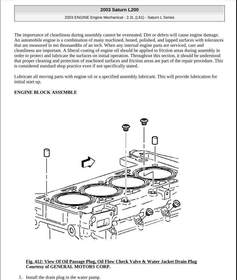
The importance of cleanliness during assembly cannot be overstated. Dirt or debris will cause engine damage. An automobile engine is a combination of many machined, honed, polished, and lapped surfaces with tolerances that are measured in ten thousandths of an inch. When any internal engine parts are serviced, care and cleanliness are important. A liberal coating of engine oil should be applied to friction areas during assembly in order to protect and lubricate the surfaces on initial operation. Throughout this section, it should be understood that proper cleaning and protection of machined surfaces and friction areas are part of the repair procedure. This is considered standard shop practice even if not specifically stated.
Lubricate all moving parts with engine oil or a specified assembly lubricant. This will provide lubrication for initial start up.
ENGINE BLOCK ASSEMBLE
Fig. 412: View Of Oil Passage Plug, Oil Flow Check Valve & Water Jacket Drain Plug Courtesy of GENERAL MOTORS CORP.
1. Install the drain plug in the water pump.
2003 Saturn L200
2003 ENGINE Engine Mechanical - 2.2L (L61) - Saturn L Series
steve
Monday, May 09, 2011 12:52:08 PM Page 472 © 2006 Mitchell Repair Information Company, LLC.
2. Apply sealant P/N 21485278, to the plug before installation.
3. Install the coolant jacket plugs.
Tighten: Tighten the coolant jacket plug to 35 N.m (26 lb ft).
4. Install the rear oil passage plugs.
5. Apply sealant P/N 21485278, to the plugs before installation.
Tighten: Tighten the oil passage plug to 60 N.m (44 lb ft).
6. Install the other oil passage plugs.
7. Apply sealant P/N 21485278, to the plug before installation.
Tighten: Tighten the oil passage plugs to 35 N.m (26 lb ft).
NOTE: Refer to FASTENER NOTICE in Cautions and Notices.
2003 Saturn L200
2003 ENGINE Engine Mechanical - 2.2L (L61) - Saturn L Series
steve
Monday, May 09, 2011 12:52:08 PM Page 473 © 2006 Mitchell Repair Information Company, LLC.
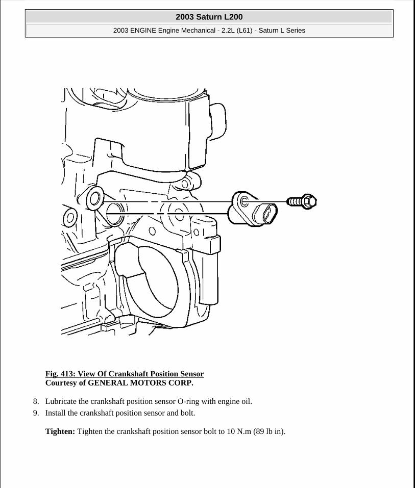
Fig. 413: View Of Crankshaft Position Sensor Courtesy of GENERAL MOTORS CORP.
8. Lubricate the crankshaft position sensor O-ring with engine oil.
9. Install the crankshaft position sensor and bolt.
Tighten: Tighten the crankshaft position sensor bolt to 10 N.m (89 lb in).
2003 Saturn L200
2003 ENGINE Engine Mechanical - 2.2L (L61) - Saturn L Series
steve
Monday, May 09, 2011 12:52:08 PM Page 474 © 2006 Mitchell Repair Information Company, LLC.
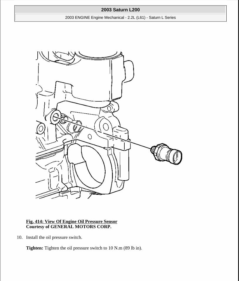
Fig. 414: View Of Engine Oil Pressure Sensor Courtesy of GENERAL MOTORS CORP.
10. Install the oil pressure switch.
Tighten: Tighten the oil pressure switch to 10 N.m (89 lb in).
2003 Saturn L200
2003 ENGINE Engine Mechanical - 2.2L (L61) - Saturn L Series
steve
Monday, May 09, 2011 12:52:08 PM Page 475 © 2006 Mitchell Repair Information Company, LLC.

Fig. 415: View of Knock Sensor Courtesy of GENERAL MOTORS CORP.
11. Install the knock sensor and bolt.
Tighten: Tighten the knock sensor bolt to 25 N.m (18 lb ft).
CRANKSHAFT AND BEARINGS INSTALLATION
Installation Procedure
2003 Saturn L200
2003 ENGINE Engine Mechanical - 2.2L (L61) - Saturn L Series
steve
Monday, May 09, 2011 12:52:08 PM Page 476 © 2006 Mitchell Repair Information Company, LLC.

Fig. 416: Inspecting Crankshaft & Connecting Rod Bearing Bores Courtesy of GENERAL MOTORS CORP.
Inspect the connecting rod bearing bores or crankshaft main bearing bores using the following procedure:
Tighten the bearing cap to specification.
Measure the bearing bore for taper and out-of-round.
No taper or out-of-round should exist.
IMPORTANT: If the crankshaft bearing failure is due to other than normal wear, investigate the cause. Inspect the crankshaft or connecting rod bearing bores.
2003 Saturn L200
2003 ENGINE Engine Mechanical - 2.2L (L61) - Saturn L Series
steve
Monday, May 09, 2011 12:52:08 PM Page 477 © 2006 Mitchell Repair Information Company, LLC.

Bearing Selection
Fig. 417: Measuring Bearing Clearance Courtesy of GENERAL MOTORS CORP.
1. Measure the bearing clearance to determine the correct replacement bearing insert size. There are 2 methods to measure bearing clearance.
Method A gives more reliable results and is preferred. Method A yields measurement from which the bearing clearance can be computed.
Method B yields the bearing clearance directly. Method B does not give any indication of bearing run-out.
2003 Saturn L200
2003 ENGINE Engine Mechanical - 2.2L (L61) - Saturn L Series
steve
Monday, May 09, 2011 12:52:08 PM Page 478 © 2006 Mitchell Repair Information Company, LLC.

2. To measure the bearing clearance using Method A, use the following procedure:
1. Measure the crankshaft bearing journal diameter with a micrometer in several places, 90° apart. Average the measurements.
2. Measure the crankshaft bearing journal taper and runout.
3. Install the inserts and lower crankcase. Tighten the bearing cap bolts to specification.
4. Measure the bearing ID in several places 90° apart. Average the measurements.
5. Subtract the journal measurement from the bearing ID measurement to determine the clearance.
6. Determine whether the clearance is within specifications. If out of specifications, choose different inserts.
7. Measure the connecting rod inside the diameter in the same direction as the length of rod with an inside micrometer.
8. Measure the crankshaft main bearing inside diameter with an inside micrometer.
IMPORTANT: Do not mix inserts of different nominal size in the same bearing bore.
2003 Saturn L200
2003 ENGINE Engine Mechanical - 2.2L (L61) - Saturn L Series
steve
Monday, May 09, 2011 12:52:08 PM Page 479 © 2006 Mitchell Repair Information Company, LLC.
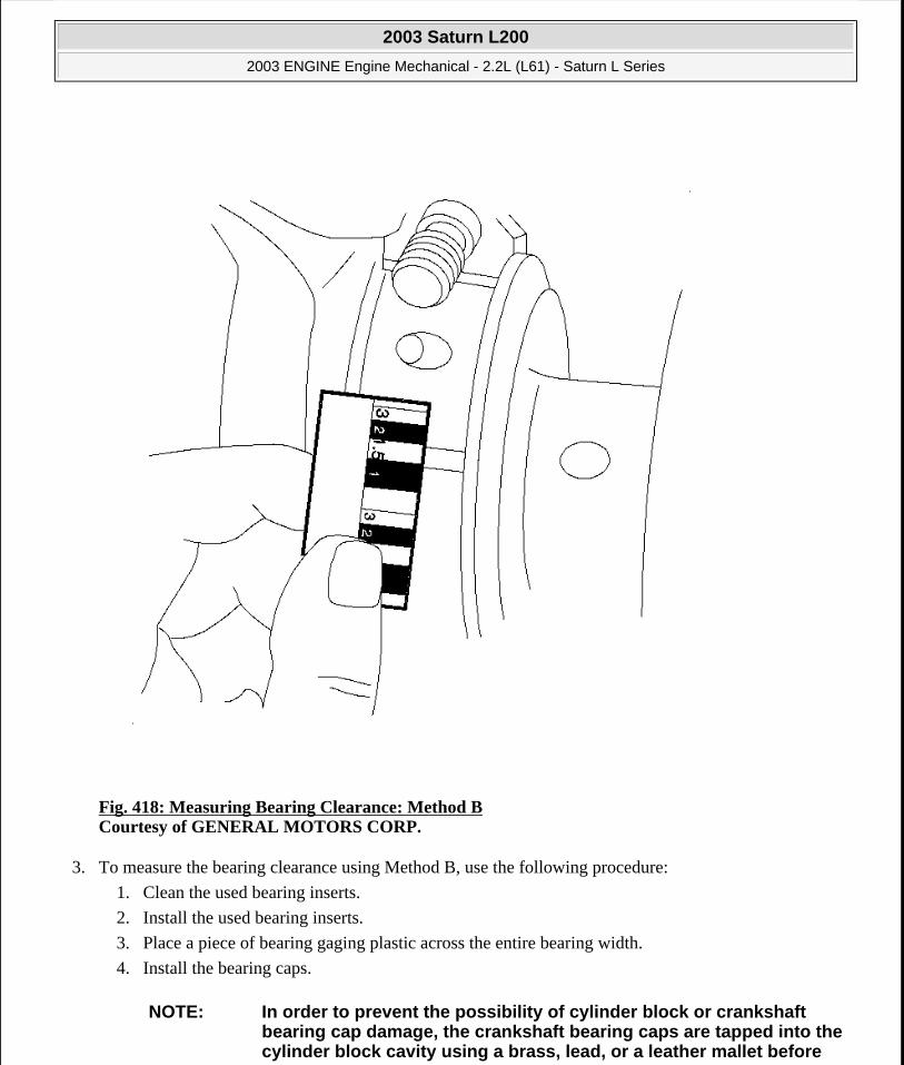
Fig. 418: Measuring Bearing Clearance: Method B Courtesy of GENERAL MOTORS CORP.
3. To measure the bearing clearance using Method B, use the following procedure:
1. Clean the used bearing inserts.
2. Install the used bearing inserts.
3. Place a piece of bearing gaging plastic across the entire bearing width.
4. Install the bearing caps.
NOTE: In order to prevent the possibility of cylinder block or crankshaft bearing cap damage, the crankshaft bearing caps are tapped into the cylinder block cavity using a brass, lead, or a leather mallet before
2003 Saturn L200
2003 ENGINE Engine Mechanical - 2.2L (L61) - Saturn L Series
steve
Monday, May 09, 2011 12:52:08 PM Page 480 © 2006 Mitchell Repair Information Company, LLC.

5. Install the bearing cap bolts.
6. Remove the bearing cap, leaving the bearing gaging plastic in place. It does not matter whether the bearing gaging plastic adheres to the journal or to the bearing cap.
7. Measure the bearing gaging plastic at its widest point with the scale printed on the gaging plastic package.
8. Remove the gaging plastic.
LOWER CRANKCASE INSTALLATION
Tolls Required
J 36660-A (SA9140E) Torque Angle Meter. See Special Tools and Equipment.
the attaching bolts are installed. Do not use attaching bolts to pull the crankshaft bearing caps into the seats. Failure to use this process may damage a cylinder block or a bearing cap.
IMPORTANT: Do not rotate the crankshaft.
2003 Saturn L200
2003 ENGINE Engine Mechanical - 2.2L (L61) - Saturn L Series
steve
Monday, May 09, 2011 12:52:08 PM Page 481 © 2006 Mitchell Repair Information Company, LLC.

Fig. 419: View Of Crankshaft Bearing Inserts Courtesy of GENERAL MOTORS CORP.
1. Install the crankshaft bearings and lubricate bearing surfaces with engine oil.
2003 Saturn L200
2003 ENGINE Engine Mechanical - 2.2L (L61) - Saturn L Series
steve
Monday, May 09, 2011 12:52:08 PM Page 482 © 2006 Mitchell Repair Information Company, LLC.
Fig. 420: Identifying Crankshaft Courtesy of GENERAL MOTORS CORP.
2. Install the crankshaft on the journals.
2003 Saturn L200
2003 ENGINE Engine Mechanical - 2.2L (L61) - Saturn L Series
steve
Monday, May 09, 2011 12:52:08 PM Page 483 © 2006 Mitchell Repair Information Company, LLC.
Fig. 421: Applying Sealer to Engine Block to Bedplate Mating Surfaces Courtesy of GENERAL MOTORS CORP.
3. Apply sealer P/N 21019581, to the surfaces of the engine block to bedplate mating surfaces.
2003 Saturn L200
2003 ENGINE Engine Mechanical - 2.2L (L61) - Saturn L Series
steve
Monday, May 09, 2011 12:52:08 PM Page 484 © 2006 Mitchell Repair Information Company, LLC.

Fig. 422: Identifying Crankshaft Bearing Inserts Courtesy of GENERAL MOTORS CORP.
4. Install the lower bearing halves, without grooves, into the lower crankcase. Apply oil to bearing surfaces.
2003 Saturn L200
2003 ENGINE Engine Mechanical - 2.2L (L61) - Saturn L Series
steve
Monday, May 09, 2011 12:52:08 PM Page 485 © 2006 Mitchell Repair Information Company, LLC.

Fig. 423: View Of Upper & Lower Crankcase W/Bolts Courtesy of GENERAL MOTORS CORP.
5. Install the lower crankcase. Tap gently into place with a suitable tool if necessary. Ensure it is aligned properly on the dowels.
2003 Saturn L200
2003 ENGINE Engine Mechanical - 2.2L (L61) - Saturn L Series
steve
Monday, May 09, 2011 12:52:08 PM Page 486 © 2006 Mitchell Repair Information Company, LLC.

Fig. 424: Identifying Crankshaft Bearing Bolt Tightening Sequence Courtesy of GENERAL MOTORS CORP.
6. Install the crankshaft bearing bolts in sequence finger tight.
1. Tighten the crankshaft bearing bolts in sequence.
Tighten: Tighten the crankshaft bearing bolts to 20 N.m (15 lb ft).
2. Tighten the crankshaft bearing bolts in sequence.
Tighten: Tighten the crankshaft bearing bolts 70 degrees using the J 36660-A (SA9140E). See Special Tools and Equipment.
NOTE: Refer to FASTENER NOTICE in Cautions and Notices.
2003 Saturn L200
2003 ENGINE Engine Mechanical - 2.2L (L61) - Saturn L Series
steve
Monday, May 09, 2011 12:52:08 PM Page 487 © 2006 Mitchell Repair Information Company, LLC.

Fig. 425: Lower Crankcase Perimeter Bolt Tightening Sequence Courtesy of GENERAL MOTORS CORP.
7. Tighten the lower crankcase perimeter bolts in sequence.
Tighten: Tighten the lower crankcase perimeter bolts to 25 N.m (18 lb ft).
CRANKSHAFT REAR OIL SEAL INSTALLATION
Tools Required
J 42067 Rear Crankshaft Seal Installer. See Special Tools and Equipment.
Installation Procedure
2003 Saturn L200
2003 ENGINE Engine Mechanical - 2.2L (L61) - Saturn L Series
steve
Monday, May 09, 2011 12:52:08 PM Page 488 © 2006 Mitchell Repair Information Company, LLC.

Fig. 426: Removing Seal Recess Courtesy of GENERAL MOTORS CORP.
1. Remove the excess sealer from the seal recess.
2. Lubricate the outside diameter of the crankshaft seal with clean engine oil.
3. Press the new crankshaft seal into housing, using the J 42067 . See Special Tools and Equipment. The installer also establishes the depth of the seal in the crankshaft seal bore.
PISTON, CONNECTING ROD, AND BEARING INSTALLATION
Tools Required
J 41742 Connecting Rod Guide. See Special Tools and Equipment.
2003 Saturn L200
2003 ENGINE Engine Mechanical - 2.2L (L61) - Saturn L Series
steve
Monday, May 09, 2011 12:52:08 PM Page 489 © 2006 Mitchell Repair Information Company, LLC.

J 43953 Piston Ring Compressor. See Special Tools and Equipment.
Installation Procedure
Fig. 427: Installing Connecting Rod Bearings Courtesy of GENERAL MOTORS CORP.
1. Install the connecting rod bearings. Use the proper size bearings.
1. Install the bearing inserts into the connecting rod and the connecting rod cap.
2. Lubricate the connecting rod bearings with clean engine oil.
2. Install the J 41742 into the connecting rod bolt holes This protects the crankshaft journal during piston and connecting rod installation. See Special Tools and Equipment.
2003 Saturn L200
2003 ENGINE Engine Mechanical - 2.2L (L61) - Saturn L Series
steve
Monday, May 09, 2011 12:52:08 PM Page 490 © 2006 Mitchell Repair Information Company, LLC.

3. Install the piston and connecting rod into the cylinder.
1. Stagger each piston ring end gap equally around the piston.
2. Lubricate the piston and piston rings with clean engine oil.
3. Install the J 43953 over the piston. See Special Tools and Equipment. Do not disturb the piston ring end gap location.
4. The piston must be installed so that the arrow on top of the piston faces the front of the engine.
5. Place the piston in its matching bore.
6. Push the piston into its bore with a hammer handle. Guide the connecting rod to connecting rod journal while tapping the piston into place.
7. Hold the J 43953 against the engine block until all rings have entered the cylinder bore. See Special Tools and Equipment.
8. Remove the connecting rod guides from the connecting rod bolt holes.
2003 Saturn L200
2003 ENGINE Engine Mechanical - 2.2L (L61) - Saturn L Series
steve
Monday, May 09, 2011 12:52:08 PM Page 491 © 2006 Mitchell Repair Information Company, LLC.
Fig. 428: Installing Connecting Rod Cap Courtesy of GENERAL MOTORS CORP.
4. Install the connecting rod cap.
5. Install the connecting rod bolts.
IMPORTANT: Ensure that the connecting rod cap is properly oriented on the connecting rod.
IMPORTANT: Always use new bolts.
2003 Saturn L200
2003 ENGINE Engine Mechanical - 2.2L (L61) - Saturn L Series
steve
Monday, May 09, 2011 12:52:08 PM Page 492 © 2006 Mitchell Repair Information Company, LLC.
Tighten: Tighten the connecting rod bolts to 25 N.m (18 lb ft) plus 100 degrees.
6. Install the remaining connecting piston and rod assemblies.
Fig. 429: Measuring Connecting Rod Side Clearance Courtesy of GENERAL MOTORS CORP.
7. Measure the connecting rod side clearance with a feeler gage.
Tighten: Tighten the connecting rod side clearance to 0.07-0.37 mm (0.0027-0.0145 in).
CYLINDER HEAD INSTALLATION
2003 Saturn L200
2003 ENGINE Engine Mechanical - 2.2L (L61) - Saturn L Series
steve
Monday, May 09, 2011 12:52:08 PM Page 493 © 2006 Mitchell Repair Information Company, LLC.

J 36660-A (SA9140E) Torque Angle Meter. See Special Tools and Equipment.
Fig. 430: View Of Cylinder Head And Gasket Courtesy of GENERAL MOTORS CORP.
1. Install the cylinder head gasket to the block.
2. Install the cylinder head.
IMPORTANT: Do not use any sealing material.
IMPORTANT: Always use new cylinder head bolts.
2003 Saturn L200
2003 ENGINE Engine Mechanical - 2.2L (L61) - Saturn L Series
steve
Monday, May 09, 2011 12:52:08 PM Page 494 © 2006 Mitchell Repair Information Company, LLC.

3. Lightly apply clean engine oil to the threads and the bottom side of the flange of the head bolt and allow the oil to drain before installing.
Fig. 431: Identifying Cylinder Head Bolt Tightening Sequence Courtesy of GENERAL MOTORS CORP.
4. Install and tighten the cylinder head bolts in sequence.
Tighten:
Tighten bolts 30 N.m (22 lb ft).
Then turn all the bolts 155 degrees in sequence. Use the J 36660-A (SA9140E). See Special Tools and Equipment.
NOTE: Refer to FASTENER NOTICE in Cautions and Notices.
2003 Saturn L200
2003 ENGINE Engine Mechanical - 2.2L (L61) - Saturn L Series
steve
Monday, May 09, 2011 12:52:08 PM Page 495 © 2006 Mitchell Repair Information Company, LLC.

Fig. 432: Locating Front Cylinder Head Bolts Courtesy of GENERAL MOTORS CORP.
5. Install the front cylinder head bolts.
Tighten: Tighten the cylinder head bolts to 35 N.m (26 lb ft).
2003 Saturn L200
2003 ENGINE Engine Mechanical - 2.2L (L61) - Saturn L Series
steve
Monday, May 09, 2011 12:52:08 PM Page 496 © 2006 Mitchell Repair Information Company, LLC.

Fig. 433: Removing & Installing EGR Cover & Gasket Courtesy of GENERAL MOTORS CORP.
6. Install the EGR cover (2), the bolts (1), and the EGR cover gasket (3).
Tighten: Tighten the EGR cover bolts to 25 N.m (18 lb ft).
Tools Required
INTAKE CAMSHAFT, FOLLOWER, AND ADJUSTER INSTALL
2003 Saturn L200
2003 ENGINE Engine Mechanical - 2.2L (L61) - Saturn L Series
steve
Monday, May 09, 2011 12:52:08 PM Page 497 © 2006 Mitchell Repair Information Company, LLC.
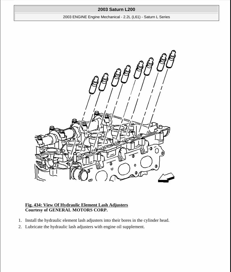
Fig. 434: View Of Hydraulic Element Lash Adjusters Courtesy of GENERAL MOTORS CORP.
1. Install the hydraulic element lash adjusters into their bores in the cylinder head.
2. Lubricate the hydraulic lash adjusters with engine oil supplement.
2003 Saturn L200
2003 ENGINE Engine Mechanical - 2.2L (L61) - Saturn L Series
steve
Monday, May 09, 2011 12:52:08 PM Page 498 © 2006 Mitchell Repair Information Company, LLC.

Fig. 435: Lubricating Valve Tips Courtesy of GENERAL MOTORS CORP.
3. Lubricate the valve tips with engine oil supplement.
2003 Saturn L200
2003 ENGINE Engine Mechanical - 2.2L (L61) - Saturn L Series
steve
Monday, May 09, 2011 12:52:08 PM Page 499 © 2006 Mitchell Repair Information Company, LLC.

Fig. 436: View Of Camshaft Roller Followers Courtesy of GENERAL MOTORS CORP.
4. Position the roller followers on the tip of the valve stem and on the lash adjuster. Lubricate the roller followers with engine oil supplement.
IMPORTANT: Used roller followers must be returned to the original position on the camshaft. If the camshaft is being replaced, the roller followers actuated by the camshaft must also be replaced.
2003 Saturn L200
2003 ENGINE Engine Mechanical - 2.2L (L61) - Saturn L Series
steve
Monday, May 09, 2011 12:52:08 PM Page 500 © 2006 Mitchell Repair Information Company, LLC.
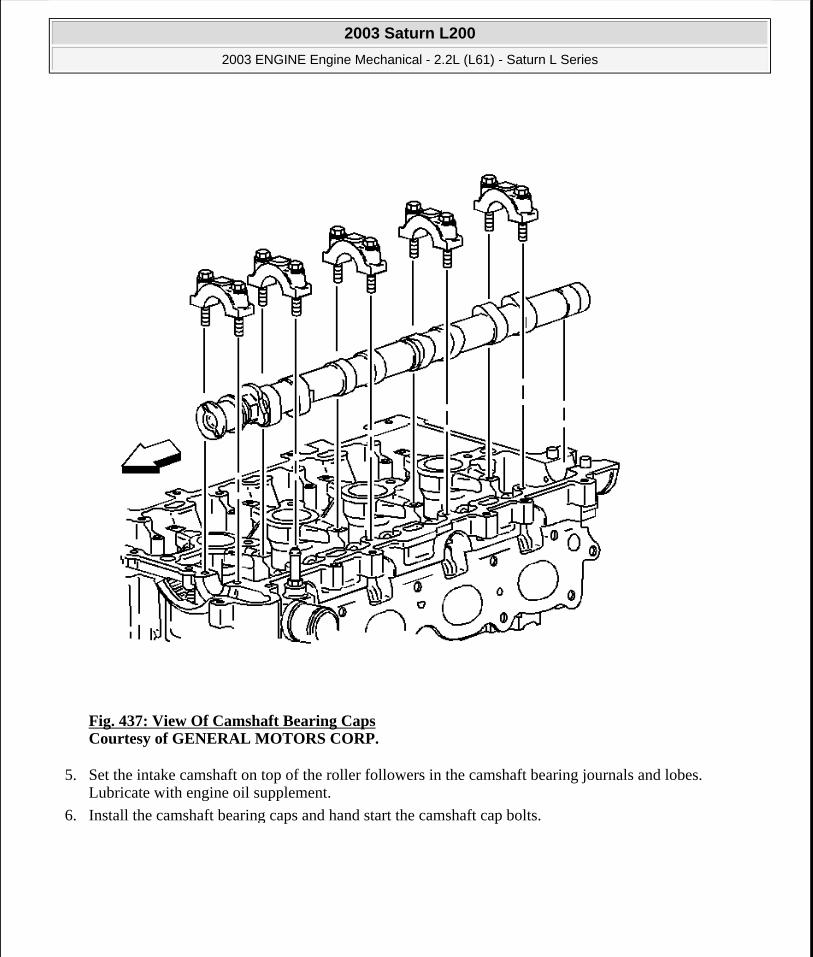
Fig. 437: View Of Camshaft Bearing Caps Courtesy of GENERAL MOTORS CORP.
5. Set the intake camshaft on top of the roller followers in the camshaft bearing journals and lobes. Lubricate with engine oil supplement.
6. Install the camshaft bearing caps and hand start the camshaft cap bolts.
2003 Saturn L200
2003 ENGINE Engine Mechanical - 2.2L (L61) - Saturn L Series
steve
Monday, May 09, 2011 12:52:08 PM Page 501 © 2006 Mitchell Repair Information Company, LLC.

Fig. 438: View Of Camshaft Alignment Notches Courtesy of GENERAL MOTORS CORP.
7. The timing chain sprocket alignment notch should be oriented to the eleven o'clock position.
8. Tighten the camshaft bearing cap bolts in increments of three turns until they are seated.
Tighten: Tighten the camshaft bearing caps to 10 N.m (89 lb in).
NOTE: Refer to FASTENER NOTICE in Cautions and Notices.
2003 Saturn L200
2003 ENGINE Engine Mechanical - 2.2L (L61) - Saturn L Series
steve
Monday, May 09, 2011 12:52:08 PM Page 502 © 2006 Mitchell Repair Information Company, LLC.

Fig. 439: Applying Camshaft Bearing Cap Sealer To Rear Cap Courtesy of GENERAL MOTORS CORP.
9. Apply Permatex® Anaerobic Gasket Maker 51813, 3.5 mm (0.138 in) bead, to rear intake camshaft bearing cap.
10. Install the rear intake camshaft bearing cap bolts.
Tighten: Tighten the bolts to 25 N.m (18 lb ft).
EXHAUST CAMSHAFT, FOLLOWER, AND ADJUSTER INSTALL
2003 Saturn L200
2003 ENGINE Engine Mechanical - 2.2L (L61) - Saturn L Series
steve
Monday, May 09, 2011 12:52:08 PM Page 503 © 2006 Mitchell Repair Information Company, LLC.

Fig. 440: View Of Hydraulic Element Lash Adjusters Courtesy of GENERAL MOTORS CORP.
1. Install the hydraulic element lash adjusters into their bores in the cylinder head.
2. Lubricate the hydraulic element lash adjusters with engine oil supplement.
2003 Saturn L200
2003 ENGINE Engine Mechanical - 2.2L (L61) - Saturn L Series
steve
Monday, May 09, 2011 12:52:08 PM Page 504 © 2006 Mitchell Repair Information Company, LLC.

Fig. 441: Lubricating Valve Tips Courtesy of GENERAL MOTORS CORP.
3. Lubricate the valve tips with engine oil supplement.
2003 Saturn L200
2003 ENGINE Engine Mechanical - 2.2L (L61) - Saturn L Series
steve
Monday, May 09, 2011 12:52:08 PM Page 505 © 2006 Mitchell Repair Information Company, LLC.

Fig. 442: Identifying Exhaust Camshaft Roller Followers Courtesy of GENERAL MOTORS CORP.
4. Position the roller followers on the tip of the valve stem and on the lash adjuster. Lubricate the roller followers with engine oil supplement.
IMPORTANT: Used roller followers must be returned to the original position on the camshaft. If the camshaft is being replaced, the roller followers actuated by the camshaft must also be replaced.
2003 Saturn L200
2003 ENGINE Engine Mechanical - 2.2L (L61) - Saturn L Series
steve
Monday, May 09, 2011 12:52:08 PM Page 506 © 2006 Mitchell Repair Information Company, LLC.

Fig. 443: View Of Camshaft & Bearing Caps Courtesy of GENERAL MOTORS CORP.
5. Set the exhaust camshaft on top of the roller followers in the camshaft bearing journals. Lubricate with engine oil supplement.
6. Install the camshaft bearing caps and hand start the camshaft cap bolts.
2003 Saturn L200
2003 ENGINE Engine Mechanical - 2.2L (L61) - Saturn L Series
steve
Monday, May 09, 2011 12:52:08 PM Page 507 © 2006 Mitchell Repair Information Company, LLC.

Fig. 444: Alignment Timing Chain Sprocket Notch Courtesy of GENERAL MOTORS CORP.
7. The timing chain sprocket alignment notch should be oriented to the two o' clock position.
8. Tighten the camshaft bearing cap bolts in increments of three turns until they are seated, lubricate.
Tighten: Tighten the camshaft bearing caps to 10 N.m (89 lb in).
BALANCE SHAFT INSTALLATION
NOTE: Refer to FASTENER NOTICE in Cautions and Notices.
2003 Saturn L200
2003 ENGINE Engine Mechanical - 2.2L (L61) - Saturn L Series
steve
Monday, May 09, 2011 12:52:08 PM Page 508 © 2006 Mitchell Repair Information Company, LLC.

Tools Required
J 43650 Balance Shaft Bearing Remover/Installer. See Special Tools and Equipment.
Fig. 445: Installing Balance Shaft Courtesy of GENERAL MOTORS CORP.
1. Install the balance shaft bushing using the J 43650 . See Special Tools and Equipment.
2003 Saturn L200
2003 ENGINE Engine Mechanical - 2.2L (L61) - Saturn L Series
steve
Monday, May 09, 2011 12:52:08 PM Page 509 © 2006 Mitchell Repair Information Company, LLC.

Fig. 446: Seating Balance Shaft Bushing Courtesy of GENERAL MOTORS CORP.
2. Seat the balance shaft bushing into the bore using the J 43650 and a wrench. See Special Tools and Equipment.
3. When the J 43650 is fully seated in the engine block, remove it with a wrench. See Special Tools and Equipment.
2003 Saturn L200
2003 ENGINE Engine Mechanical - 2.2L (L61) - Saturn L Series
steve
Monday, May 09, 2011 12:52:08 PM Page 510 © 2006 Mitchell Repair Information Company, LLC.

Fig. 447: Installing Balance Shaft Courtesy of GENERAL MOTORS CORP.
4. Place the number one piston at top dead center (TDC).
5. Install the balance shaft drive chain sprocket on the crankshaft
6. Install the balance shafts into their bores.
IMPORTANT: If the balance shafts are not properly timed to the engine, the engine may vibrate or make noise.
IMPORTANT: Install the balance shaft assemblies to the engine using the following steps:
2003 Saturn L200
2003 ENGINE Engine Mechanical - 2.2L (L61) - Saturn L Series
steve
Monday, May 09, 2011 12:52:08 PM Page 511 © 2006 Mitchell Repair Information Company, LLC.

7. Install the balance shaft retaining bolts.
Tighten: Tighten the balance shaft retaining bolts to 10 N.m (89 lb in).
Fig. 448: Aligning Exhaust Sprocket Arrow with Carrier Notch Courtesy of GENERAL MOTORS CORP.
8. Align the arrow on the exhaust sprocket with the notch on the carrier. The arrow should point down.
2003 Saturn L200
2003 ENGINE Engine Mechanical - 2.2L (L61) - Saturn L Series
steve
Monday, May 09, 2011 12:52:08 PM Page 512 © 2006 Mitchell Repair Information Company, LLC.

Fig. 449: Aligning Intake Sprocket Arrow with Carrier Notch Courtesy of GENERAL MOTORS CORP.
9. Align the arrow on the intake sprocket with the notch on the carrier. The arrow should point up.
WATER PUMP INSTALLATION
Prior to installing the water pump, read the entire procedure. Pay special attention to avoid part damage and to ensure proper sealing.
2003 Saturn L200
2003 ENGINE Engine Mechanical - 2.2L (L61) - Saturn L Series
steve
Monday, May 09, 2011 12:52:08 PM Page 513 © 2006 Mitchell Repair Information Company, LLC.

Fig. 450: View Of Water Pump Assembly Courtesy of GENERAL MOTORS CORP.
1. Install the water pump assembly.
2. Install the water pump bolts.
3. Tighten the water pump bolts.
Tighten: Tighten the bolts to 25 N.m (18 lb ft).
4. Apply sealant P/N 21485278 to the water pump drain plug.
5. Install the water pump drain plug, if necessary.
Tighten: Tighten the water pump drain plug to 20 N.m (15 lb ft).
NOTE: Refer to FASTENER NOTICE in Cautions and Notices.
2003 Saturn L200
2003 ENGINE Engine Mechanical - 2.2L (L61) - Saturn L Series
steve
Monday, May 09, 2011 12:52:09 PM Page 514 © 2006 Mitchell Repair Information Company, LLC.

Fig. 451: Installing Water Feed Tube & Thermostat Housing Courtesy of GENERAL MOTORS CORP.
6. Install the water feed tube.
7. Lubricate the feed tube O-Ring with anti-freeze.
8. Install the water feed tube by twisting and pushing toward the water pump. Take care not to tear or damage the O-Ring.
9. Install the thermostat housing to block bolts and stud.
Tighten: Tighten the bolts and stud to 10 N.m (89 lb in).
2003 Saturn L200
2003 ENGINE Engine Mechanical - 2.2L (L61) - Saturn L Series
steve
Monday, May 09, 2011 12:52:09 PM Page 515 © 2006 Mitchell Repair Information Company, LLC.

Fig. 452: Removing & Installing Engine Coolant Temperature Sensor Courtesy of GENERAL MOTORS CORP.
10. Install the engine coolant temperature sensor by hand.
11. Tighten the engine coolant temperature sensor.
Tighten: Tighten the engine coolant temperature sensor to 20 N.m (15 lb ft).
TIMING BALANCE SHAFTS TO ENGINE
2003 Saturn L200
2003 ENGINE Engine Mechanical - 2.2L (L61) - Saturn L Series
steve
Monday, May 09, 2011 12:52:09 PM Page 516 © 2006 Mitchell Repair Information Company, LLC.
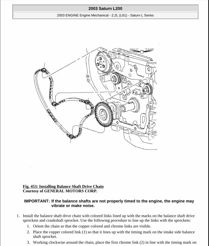
Fig. 453: Installing Balance Shaft Drive Chain Courtesy of GENERAL MOTORS CORP.
1. Install the balance shaft drive chain with colored links lined up with the marks on the balance shaft drive sprockets and crankshaft sprocket. Use the following procedure to line up the links with the sprockets:
1. Orient the chain so that the copper colored and chrome links are visible.
2. Place the copper colored link (1) so that it lines up with the timing mark on the intake side balance shaft sprocket.
3. Working clockwise around the chain, place the first chrome link (2) in line with the timing mark on
IMPORTANT: If the balance shafts are not properly timed to the engine, the engine may vibrate or make noise.
2003 Saturn L200
2003 ENGINE Engine Mechanical - 2.2L (L61) - Saturn L Series
steve
Monday, May 09, 2011 12:52:09 PM Page 517 © 2006 Mitchell Repair Information Company, LLC.
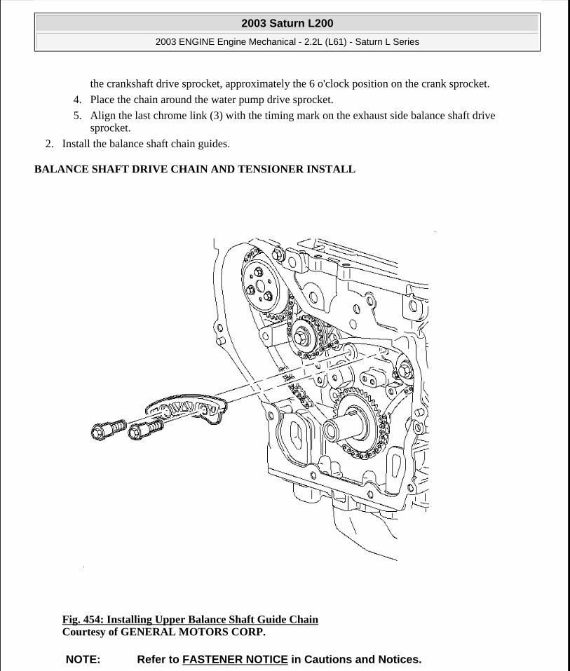
the crankshaft drive sprocket, approximately the 6 o'clock position on the crank sprocket.
4. Place the chain around the water pump drive sprocket.
5. Align the last chrome link (3) with the timing mark on the exhaust side balance shaft drive sprocket.
2. Install the balance shaft chain guides.
BALANCE SHAFT DRIVE CHAIN AND TENSIONER INSTALL
Fig. 454: Installing Upper Balance Shaft Guide Chain Courtesy of GENERAL MOTORS CORP.
NOTE: Refer to FASTENER NOTICE in Cautions and Notices.
2003 Saturn L200
2003 ENGINE Engine Mechanical - 2.2L (L61) - Saturn L Series
steve
Monday, May 09, 2011 12:52:09 PM Page 518 © 2006 Mitchell Repair Information Company, LLC.

1. Install the upper balance shaft chain guide.
Tighten: Tighten the balance shaft chain guide (upper) bolts to 10 N.m (89 lb in).
Fig. 455: Installing Small Balance Shaft Chain Guide Courtesy of GENERAL MOTORS CORP.
2. Install the small balance shaft chain guide.
3. Tighten the balance shaft chain guide bolts.
IMPORTANT: If the balance shafts are not properly timed to the engine, the engine may vibrate and make noise.
2003 Saturn L200
2003 ENGINE Engine Mechanical - 2.2L (L61) - Saturn L Series
steve
Monday, May 09, 2011 12:52:09 PM Page 519 © 2006 Mitchell Repair Information Company, LLC.

Tighten: Tighten the balance shaft chain guide (fixed) bolts to 10 N.m (89 lb in).
Fig. 456: Installing Adjustable Balance Shaft Drive Chain Guide Courtesy of GENERAL MOTORS CORP.
4. Install the adjustable balance shaft drive chain guide.
Tighten: Tighten the balance shaft chain guide (adjustable) bolt to 10 N.m (89 lb in).
2003 Saturn L200
2003 ENGINE Engine Mechanical - 2.2L (L61) - Saturn L Series
steve
Monday, May 09, 2011 12:52:09 PM Page 520 © 2006 Mitchell Repair Information Company, LLC.

Fig. 457: Installing Chain Tensioner Courtesy of GENERAL MOTORS CORP.
5. Set the chain tensioner by performing the following steps:
1. Turn the plunger 90 degrees in its bore and compress the plunger.
2. Turn the tensioner back to the 12 o'clock position and insert a paper clip through the hole on the plunger body and into the hole on the tensioner plunger.
6. Install the balance shaft drive chain tensioner.
7. Tighten the balance shaft drive chain tensioner bolts.
Tighten: Tighten the balance shaft chain tensioner bolts to 10 N.m (89 lb in).
2003 Saturn L200
2003 ENGINE Engine Mechanical - 2.2L (L61) - Saturn L Series
steve
Monday, May 09, 2011 12:52:09 PM Page 521 © 2006 Mitchell Repair Information Company, LLC.

8. Remove the paper clip from the balance shaft drive chain tensioner.
TIMING CHAIN, SPROCKETS, TENSIONER INSTALLATION
Tools Required
J 45027 Tensioner Tool. See Special Tools and Equipment.
Fig. 458: View Of Crankshaft Sprocket Timing Mark Courtesy of GENERAL MOTORS CORP.
2003 Saturn L200
2003 ENGINE Engine Mechanical - 2.2L (L61) - Saturn L Series
steve
Monday, May 09, 2011 12:52:09 PM Page 522 © 2006 Mitchell Repair Information Company, LLC.

1. Install the timing chain drive sprocket to the crankshaft with the timing mark in the 5 o'clock position.
Fig. 459: Aligning Timing Chain Link & Intake Sprocket Timing Mark Courtesy of GENERAL MOTORS CORP.
IMPORTANT: There are three colored links on the timing chain. Two links are of matching color and one link is of a unique color. Use the following procedure to line up the links with the sprockets. Orient the chain so that the colored links are visible.
Always use new sprocket bolts.
2003 Saturn L200
2003 ENGINE Engine Mechanical - 2.2L (L61) - Saturn L Series
steve
Monday, May 09, 2011 12:52:09 PM Page 523 © 2006 Mitchell Repair Information Company, LLC.

2. Assemble the intake camshaft sprocket to the timing chain with the timing mark lined up with the uniquely colored link (1). Hand tighten a new intake camshaft sprocket bolt.
Fig. 460: Locating Cylinder Block Bosses Courtesy of GENERAL MOTORS CORP.
3. Lower the timing chain through the opening in the cylinder head. Use care to ensure that the chain goes around both sides of the cylinder block bosses (1, 2).
2003 Saturn L200
2003 ENGINE Engine Mechanical - 2.2L (L61) - Saturn L Series
steve
Monday, May 09, 2011 12:52:09 PM Page 524 © 2006 Mitchell Repair Information Company, LLC.

Fig. 461: Identifying Timing Chain Colored Link & Crankshaft Sprocket Timing Mark Courtesy of GENERAL MOTORS CORP.
4. Route the timing chain around the crankshaft sprocket and line up the first matching colored link (2) with the timing mark on the crankshaft sprocket, in approximately the 5 o'clock position.
2003 Saturn L200
2003 ENGINE Engine Mechanical - 2.2L (L61) - Saturn L Series
steve
Monday, May 09, 2011 12:52:09 PM Page 525 © 2006 Mitchell Repair Information Company, LLC.

Fig. 462: View Of Timing Chain Tensioner Guide Courtesy of GENERAL MOTORS CORP.
5. Install the adjustable timing chain guide through the opening in the cylinder head and install the adjustable timing chain bolt.
NOTE: Refer to FASTENER NOTICE in Cautions and Notices.
2003 Saturn L200
2003 ENGINE Engine Mechanical - 2.2L (L61) - Saturn L Series
steve
Monday, May 09, 2011 12:52:09 PM Page 526 © 2006 Mitchell Repair Information Company, LLC.

Tighten: Tighten the adjustable timing chain guide bolt to 10 N.m (89 lb in).
Fig. 463: Identifying Exhaust Camshaft Sprocket Courtesy of GENERAL MOTORS CORP.
6. Install the exhaust camshaft sprocket and a new bolt loosely onto the exhaust camshaft.
IMPORTANT: Always install new sprocket bolts.
2003 Saturn L200
2003 ENGINE Engine Mechanical - 2.2L (L61) - Saturn L Series
steve
Monday, May 09, 2011 12:52:09 PM Page 527 © 2006 Mitchell Repair Information Company, LLC.

Fig. 464: Aligning Timing Chain Link & Exhaust Timing Mark Courtesy of GENERAL MOTORS CORP.
7. Align the timing mark on the sprocket with the last matching colored link (3). Install the bolt finger tight.
2003 Saturn L200
2003 ENGINE Engine Mechanical - 2.2L (L61) - Saturn L Series
steve
Monday, May 09, 2011 12:52:09 PM Page 528 © 2006 Mitchell Repair Information Company, LLC.

Fig. 465: Using 24 mm Wrench To Align Camshaft Courtesy of GENERAL MOTORS CORP.
8. Using a 24 mm wrench, first turn the intake camshaft until the alignment feature on the back of the camshaft sprocket seats in the notch in the front of the intake camshaft.
1. Turn the crankshaft 45 degrees in either direction.
IMPORTANT: Do not turn the camshaft more than 1/2 turn in either direction. To do so may cause valve to piston contact. This may damage a valve and/or a piston. If the camshaft is 180 degrees out of time, use the following procedure to realign the cam.
2003 Saturn L200
2003 ENGINE Engine Mechanical - 2.2L (L61) - Saturn L Series
steve
Monday, May 09, 2011 12:52:09 PM Page 529 © 2006 Mitchell Repair Information Company, LLC.

2. Turn the intake cam to the appropriate location.
3. Turn the crankshaft back to top dead center.
9. When the sprocket seats on the cam, tighten the sprocket bolt hand tight.
10. Verify that all of the colored links and the appropriate timing marks are still aligned. If they are not, repeat the portion of the procedure necessary to align the timing marks.
Fig. 466: View Of Fixed Timing Chain Guide Courtesy of GENERAL MOTORS CORP.
11. Install the fixed timing chain guide.
2003 Saturn L200
2003 ENGINE Engine Mechanical - 2.2L (L61) - Saturn L Series
steve
Monday, May 09, 2011 12:52:09 PM Page 530 © 2006 Mitchell Repair Information Company, LLC.
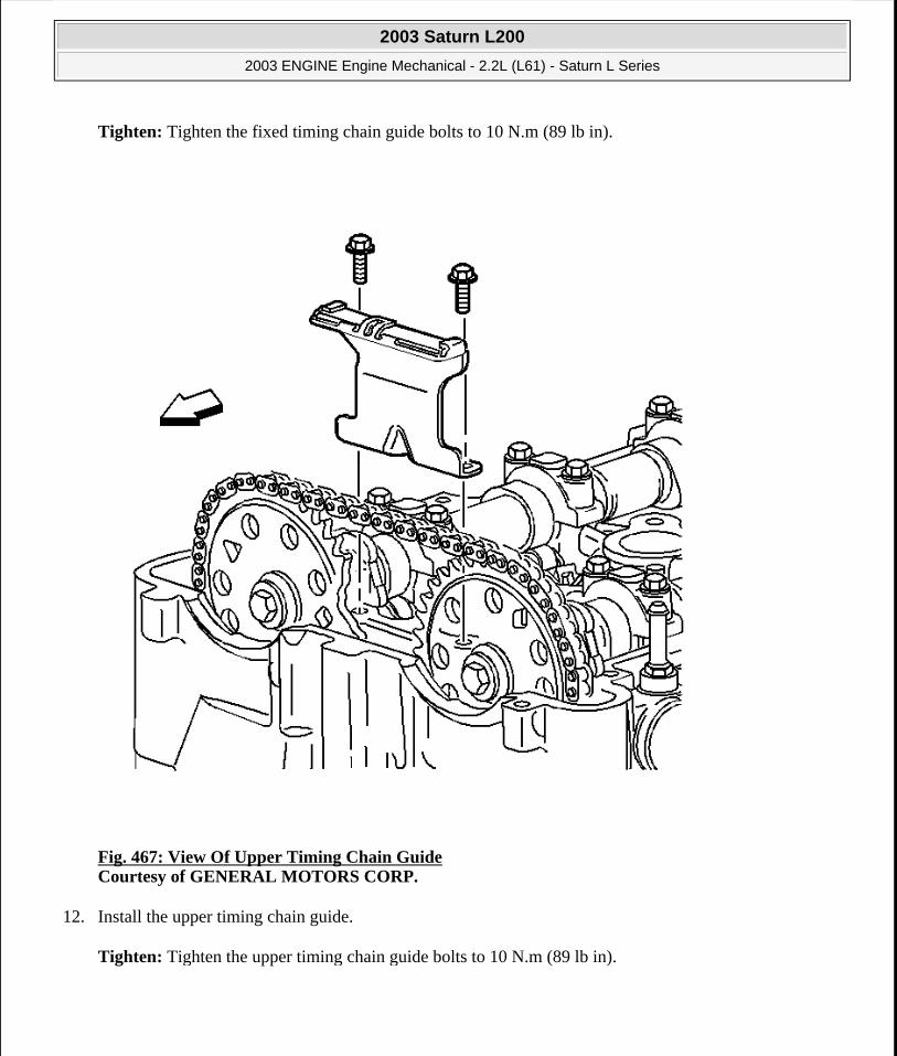
Tighten: Tighten the fixed timing chain guide bolts to 10 N.m (89 lb in).
Fig. 467: View Of Upper Timing Chain Guide Courtesy of GENERAL MOTORS CORP.
12. Install the upper timing chain guide.
Tighten: Tighten the upper timing chain guide bolts to 10 N.m (89 lb in).
2003 Saturn L200
2003 ENGINE Engine Mechanical - 2.2L (L61) - Saturn L Series
steve
Monday, May 09, 2011 12:52:09 PM Page 531 © 2006 Mitchell Repair Information Company, LLC.
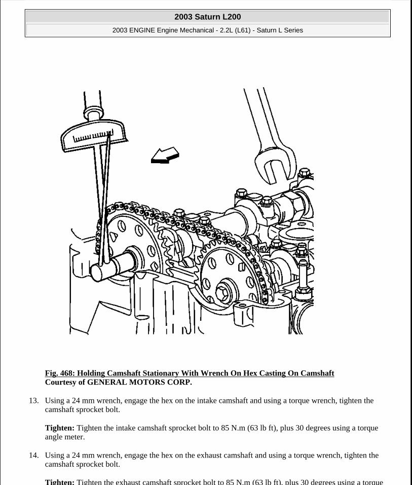
Fig. 468: Holding Camshaft Stationary With Wrench On Hex Casting On Camshaft Courtesy of GENERAL MOTORS CORP.
13. Using a 24 mm wrench, engage the hex on the intake camshaft and using a torque wrench, tighten the camshaft sprocket bolt.
Tighten: Tighten the intake camshaft sprocket bolt to 85 N.m (63 lb ft), plus 30 degrees using a torque angle meter.
14. Using a 24 mm wrench, engage the hex on the exhaust camshaft and using a torque wrench, tighten the camshaft sprocket bolt.
Tighten: Tighten the exhaust camshaft sprocket bolt to 85 N.m (63 lb ft), plus 30 degrees using a torque
2003 Saturn L200
2003 ENGINE Engine Mechanical - 2.2L (L61) - Saturn L Series
steve
Monday, May 09, 2011 12:52:09 PM Page 532 © 2006 Mitchell Repair Information Company, LLC.

angle meter.
Fig. 469: Measuring Timing Chain Tensioner Assembly Courtesy of GENERAL MOTORS CORP.
15. Remove the old oil from the timing chain tensioner.
16. Inspect the timing chain tensioner for scoring or free movement.
17. Inspect the timing chain washer and O-ring for damage. If damaged, replace the timing chain tensioner.
18. Measure the timing chain tensioner assembly from end to end.
A new tensioner should be supplied in the fully compressed non-active state. A tensioner in the compressed state will measure 72 mm (2.83 in) (a) from end to end. A tensioner in the active state will measure 85 mm (3.35 in) (a) from end to end.
2003 Saturn L200
2003 ENGINE Engine Mechanical - 2.2L (L61) - Saturn L Series
steve
Monday, May 09, 2011 12:52:09 PM Page 533 © 2006 Mitchell Repair Information Company, LLC.

Fig. 470: Compressing Timing Chain Tensioner Courtesy of GENERAL MOTORS CORP.
19. If the timing chain tensioner is not in the compressed state, perform the following steps:
1. Remove the piston assembly from the body of the timing chain tensioner by pulling it out.
2. Install the J 45027-2 (2) into a vise.
2003 Saturn L200
2003 ENGINE Engine Mechanical - 2.2L (L61) - Saturn L Series
steve
Monday, May 09, 2011 12:52:09 PM Page 534 © 2006 Mitchell Repair Information Company, LLC.

3. Install the notch end of the piston assembly into the J 45027-2 (2).
4. Using the J 45027-1 (1), turn the ratchet cylinder into the piston.
Fig. 471: Measuring Timing Chain Tensioner Assembly Courtesy of GENERAL MOTORS CORP.
20. Inspect the bore of the tensioner body for dirt, debris, and damage. If any damage appears, replace the tensioner. Clean dirt or debris out with a lint free cloth.
21. Install the compressed piston assembly back into the timing chain tensioner body until it stops at the bottom of the bore. Do not compress the piston assembly against the bottom of the bore. If the piston assembly is compressed against the bottom of the bore, it will activate the tensioner, which will then need to be reset again.
22. At this point the tensioner should measure approximately 72 mm (2.83 in) (a) from end to end. If the tensioner does not read 72 mm (2.83 in) (a) from end to end repeat steps 16.1 and 16.4.
2003 Saturn L200
2003 ENGINE Engine Mechanical - 2.2L (L61) - Saturn L Series
steve
Monday, May 09, 2011 12:52:09 PM Page 535 © 2006 Mitchell Repair Information Company, LLC.

Fig. 472: Identifying Timing Chain Tensioner Courtesy of GENERAL MOTORS CORP.
23. Inspect to ensure all dirt and debris is removed from the timing chain tensioner threaded hole in the cylinder head.
24. Install the timing chain tensioner assembly.
Tighten: Tighten the timing chain tensioner to 75 N.m (55 lb ft).
25. The timing chain tensioner is released by compressing it 2 mm (0.079 in) which will release the locking mechanism in the ratchet. To release the timing chain tensioner, use a suitable tool with a rubber tip on the end. Feed the tool down through the cam drive chest to rest on the cam chain. Then give a sharp jolt diagonally downwards to release the tensioner.
2003 Saturn L200
2003 ENGINE Engine Mechanical - 2.2L (L61) - Saturn L Series
steve
Monday, May 09, 2011 12:52:09 PM Page 536 © 2006 Mitchell Repair Information Company, LLC.

Fig. 473: View Of Oil Nozzle & Bolt Courtesy of GENERAL MOTORS CORP.
26. Inspect to ensure that all dirt and debris is removed from the timing chain oiling nozzle hole in the engine block.
27. Install the timing chain oiling nozzle.
Tighten: Tighten the timing chain oiling nozzle bolt to 10 N.m (89 lb in).
2003 Saturn L200
2003 ENGINE Engine Mechanical - 2.2L (L61) - Saturn L Series
steve
Monday, May 09, 2011 12:52:09 PM Page 537 © 2006 Mitchell Repair Information Company, LLC.
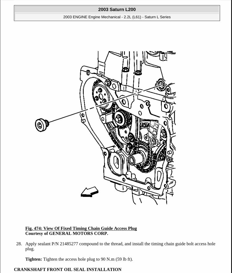
Fig. 474: View Of Fixed Timing Chain Guide Access Plug Courtesy of GENERAL MOTORS CORP.
28. Apply sealant P/N 21485277 compound to the thread, and install the timing chain guide bolt access hole plug.
Tighten: Tighten the access hole plug to 90 N.m (59 lb ft).
CRANKSHAFT FRONT OIL SEAL INSTALLATION
2003 Saturn L200
2003 ENGINE Engine Mechanical - 2.2L (L61) - Saturn L Series
steve
Monday, May 09, 2011 12:52:09 PM Page 538 © 2006 Mitchell Repair Information Company, LLC.

Tools Required
SA9107T Converter Seal Replacer
Installation Procedure
Fig. 475: Installing Crankshaft Front Oil Seal Courtesy of GENERAL MOTORS CORP.
Install the seal into the front cover by driving it in from the timing chain side using the SA9107T .
IMPORTANT: Ensure that the engine front cover is properly supported when installing the seal.
2003 Saturn L200
2003 ENGINE Engine Mechanical - 2.2L (L61) - Saturn L Series
steve
Monday, May 09, 2011 12:52:09 PM Page 539 © 2006 Mitchell Repair Information Company, LLC.
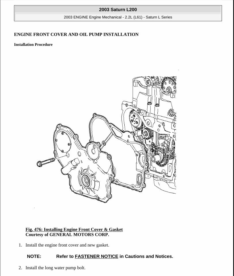
ENGINE FRONT COVER AND OIL PUMP INSTALLATION
Installation Procedure
Fig. 476: Installing Engine Front Cover & Gasket Courtesy of GENERAL MOTORS CORP.
1. Install the engine front cover and new gasket.
2. Install the long water pump bolt.
NOTE: Refer to FASTENER NOTICE in Cautions and Notices.
2003 Saturn L200
2003 ENGINE Engine Mechanical - 2.2L (L61) - Saturn L Series
steve
Monday, May 09, 2011 12:52:09 PM Page 540 © 2006 Mitchell Repair Information Company, LLC.

Tighten: Tighten the water pump bolt to 25 N.m (18 lb ft).
Fig. 477: Installing Engine Front Cover Courtesy of GENERAL MOTORS CORP.
3. Install the engine front cover bolts.
Tighten: Tighten the front cover-to-block bolts to 25 N.m (18 lb ft).
2003 Saturn L200
2003 ENGINE Engine Mechanical - 2.2L (L61) - Saturn L Series
steve
Monday, May 09, 2011 12:52:09 PM Page 541 © 2006 Mitchell Repair Information Company, LLC.

Fig. 478: Removing & Installing Belt Tensioner Bolt Courtesy of GENERAL MOTORS CORP.
4. Install the accessory drive belt tensioner.
Tighten: Tighten the drive belt tensioner bolt to 45 N.m (33 lb ft).
CAMSHAFT COVER INSTALLATION
Installation Procedure
2003 Saturn L200
2003 ENGINE Engine Mechanical - 2.2L (L61) - Saturn L Series
steve
Monday, May 09, 2011 12:52:09 PM Page 542 © 2006 Mitchell Repair Information Company, LLC.
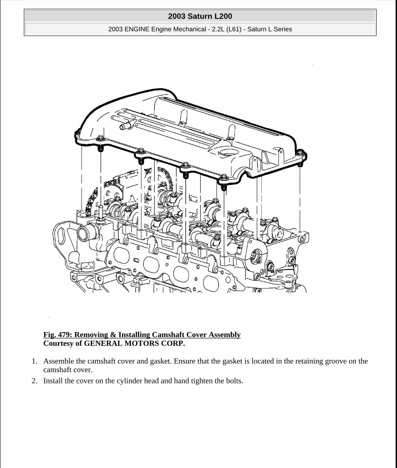
Fig. 479: Removing & Installing Camshaft Cover Assembly Courtesy of GENERAL MOTORS CORP.
1. Assemble the camshaft cover and gasket. Ensure that the gasket is located in the retaining groove on the camshaft cover.
2. Install the cover on the cylinder head and hand tighten the bolts.
2003 Saturn L200
2003 ENGINE Engine Mechanical - 2.2L (L61) - Saturn L Series
steve
Monday, May 09, 2011 12:52:09 PM Page 543 © 2006 Mitchell Repair Information Company, LLC.

Fig. 480: Installing Front Lift Bracket Courtesy of GENERAL MOTORS CORP.
3. Install the front lift bracket and tighten the bolts.
Tighten: Tighten the front lift bracket bolts to 25 N.m (18 lb ft).
2003 Saturn L200
2003 ENGINE Engine Mechanical - 2.2L (L61) - Saturn L Series
steve
Monday, May 09, 2011 12:52:09 PM Page 544 © 2006 Mitchell Repair Information Company, LLC.

Fig. 481: Installing Rear Lift Bracket Courtesy of GENERAL MOTORS CORP.
4. Install the rear lift bracket and tighten the bolts.
Tighten: Tighten the rear lift bracket bolts to 25 N.m (18 lb ft).
2003 Saturn L200
2003 ENGINE Engine Mechanical - 2.2L (L61) - Saturn L Series
steve
Monday, May 09, 2011 12:52:09 PM Page 545 © 2006 Mitchell Repair Information Company, LLC.

Fig. 482: Disconnecting/Connecting Ground Strap On The Camshaft Cover Assembly Courtesy of GENERAL MOTORS CORP.
5. Install the ground strap.
Tighten:
Tighten the camshaft cover bolts to 10 N.m (89 lb in).
Tighten the camshaft cover ground strap bolts to 10 N.m (89 lb in).
2003 Saturn L200
2003 ENGINE Engine Mechanical - 2.2L (L61) - Saturn L Series
steve
Monday, May 09, 2011 12:52:09 PM Page 546 © 2006 Mitchell Repair Information Company, LLC.

Fig. 483: Installing Spark Plugs Courtesy of GENERAL MOTORS CORP.
6. Install the spark plugs.
2003 Saturn L200
2003 ENGINE Engine Mechanical - 2.2L (L61) - Saturn L Series
steve
Monday, May 09, 2011 12:52:09 PM Page 547 © 2006 Mitchell Repair Information Company, LLC.

Fig. 484: Installing Ignition Module Assembly Courtesy of GENERAL MOTORS CORP.
7. Install the ignition coil and module assembly to the cam cover.
Tighten: Tighten the ignition coil-to-camshaft cover bolts to 8 N.m (71 lb in).
8. Install the power steering pump, if equipped.
Tighten: Tighten the power steering pump to 25 N.m (18 lb ft).
OIL PAN INSTALLATION
2003 Saturn L200
2003 ENGINE Engine Mechanical - 2.2L (L61) - Saturn L Series
steve
Monday, May 09, 2011 12:52:09 PM Page 548 © 2006 Mitchell Repair Information Company, LLC.

Fig. 485: Installing Oil Pan Courtesy of GENERAL MOTORS CORP.
1. Make sure that the oil pan and mounting surface on the lower crankcase are free of all oil and debris.
2. Apply a 2 mm (0.08 in) bead of RTV P/N 12346286 around the perimeter of the oil pan and suction port opening. Do not apply more than a 2 mm (0.08 in) bead.
3. Install the oil pan.
IMPORTANT: Ensure that there is not any excessive RTV around the oil pickup gallery flange area.
2003 Saturn L200
2003 ENGINE Engine Mechanical - 2.2L (L61) - Saturn L Series
steve
Monday, May 09, 2011 12:52:09 PM Page 549 © 2006 Mitchell Repair Information Company, LLC.
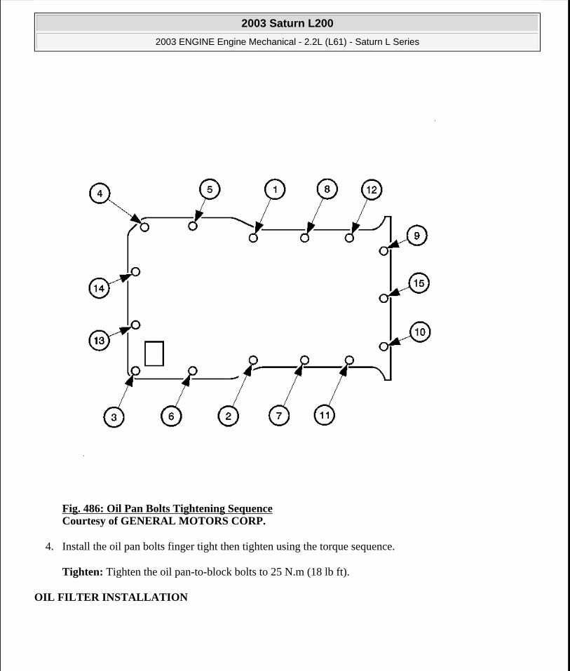
Fig. 486: Oil Pan Bolts Tightening Sequence Courtesy of GENERAL MOTORS CORP.
4. Install the oil pan bolts finger tight then tighten using the torque sequence.
Tighten: Tighten the oil pan-to-block bolts to 25 N.m (18 lb ft).
OIL FILTER INSTALLATION
2003 Saturn L200
2003 ENGINE Engine Mechanical - 2.2L (L61) - Saturn L Series
steve
Monday, May 09, 2011 12:52:09 PM Page 550 © 2006 Mitchell Repair Information Company, LLC.

Fig. 487: Removing/Installing Oil Filter Cap Courtesy of GENERAL MOTORS CORP.
1. Install the new oil filter on the oil filter cap.
2. Lubricate the O-ring on the oil filter cap with clean 5W-30 engine oil.
3. Install the oil filter cap.
Tighten: Tighten the oil filter cap to 25 N.m (18 lb ft).
NOTE: Do not use a universal type oil filter wrench to remove oil filter cap. Damage to the oil cap and the engine may result.
2003 Saturn L200
2003 ENGINE Engine Mechanical - 2.2L (L61) - Saturn L Series
steve
Monday, May 09, 2011 12:52:09 PM Page 551 © 2006 Mitchell Repair Information Company, LLC.

INTAKE MANIFOLD INSTALLATION
Fig. 488: Installing Intake Manifold Studs Courtesy of GENERAL MOTORS CORP.
1. Install the intake manifold studs in the cylinder head.
Tighten: Tighten the intake manifold-to-cylinder head studs to 6 N.m (60 lb in).
NOTE: Refer to FASTENER NOTICE in Cautions and Notices.
2003 Saturn L200
2003 ENGINE Engine Mechanical - 2.2L (L61) - Saturn L Series
steve
Monday, May 09, 2011 12:52:09 PM Page 552 © 2006 Mitchell Repair Information Company, LLC.

Fig. 489: Installing Intake Manifold Courtesy of GENERAL MOTORS CORP.
2. Install a new intake manifold gasket onto the intake manifold.
3. Install the intake manifold.
4. Install the intake manifold bolts and nuts. Tighten by starting from the center bolt and working outward.
Tighten:
Tighten the intake manifold-to-cylinder head bolts to 10 N.m (89 lb in).
Tighten the intake manifold-to-cylinder head nuts to 10 N.m (89 lb in).
2003 Saturn L200
2003 ENGINE Engine Mechanical - 2.2L (L61) - Saturn L Series
steve
Monday, May 09, 2011 12:52:09 PM Page 553 © 2006 Mitchell Repair Information Company, LLC.

Fig. 490: Removing & Installing Fuel Rail Assembly Courtesy of GENERAL MOTORS CORP.
5. Install the fuel rail assembly.
6. Install the fuel rail stud.
Tighten: Tighten the fuel rail bracket stud to 10 N.m (89 lb in).
2003 Saturn L200
2003 ENGINE Engine Mechanical - 2.2L (L61) - Saturn L Series
steve
Monday, May 09, 2011 12:52:10 PM Page 554 © 2006 Mitchell Repair Information Company, LLC.

Fig. 491: Removing & Installing Throttle Body Assembly Courtesy of GENERAL MOTORS CORP.
7. Install the throttle body. The gasket may be reused if not damaged.
Tighten: Tighten the throttle body bolts to 10 N.m (89 lb in).
2003 Saturn L200
2003 ENGINE Engine Mechanical - 2.2L (L61) - Saturn L Series
steve
Monday, May 09, 2011 12:52:10 PM Page 555 © 2006 Mitchell Repair Information Company, LLC.

Fig. 492: Identifying Fuel Pressure Regulator Hose Courtesy of GENERAL MOTORS CORP.
8. Install the pressure regulator vacuum harness.
2003 Saturn L200
2003 ENGINE Engine Mechanical - 2.2L (L61) - Saturn L Series
steve
Monday, May 09, 2011 12:52:10 PM Page 556 © 2006 Mitchell Repair Information Company, LLC.
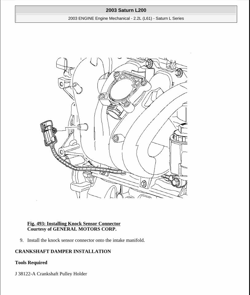
Fig. 493: Installing Knock Sensor Connector Courtesy of GENERAL MOTORS CORP.
9. Install the knock sensor connector onto the intake manifold.
CRANKSHAFT DAMPER INSTALLATION
Tools Required
J 38122-A Crankshaft Pulley Holder
2003 Saturn L200
2003 ENGINE Engine Mechanical - 2.2L (L61) - Saturn L Series
steve
Monday, May 09, 2011 12:52:10 PM Page 557 © 2006 Mitchell Repair Information Company, LLC.
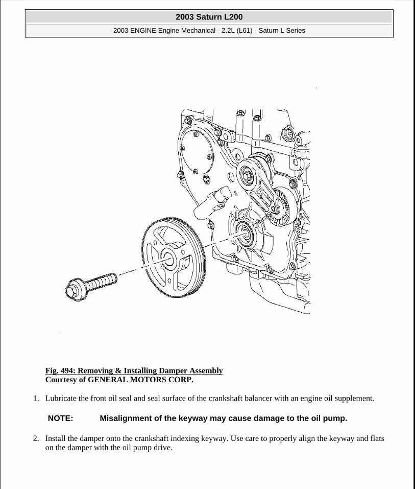
Fig. 494: Removing & Installing Damper Assembly Courtesy of GENERAL MOTORS CORP.
1. Lubricate the front oil seal and seal surface of the crankshaft balancer with an engine oil supplement.
2. Install the damper onto the crankshaft indexing keyway. Use care to properly align the keyway and flats on the damper with the oil pump drive.
NOTE: Misalignment of the keyway may cause damage to the oil pump.
2003 Saturn L200
2003 ENGINE Engine Mechanical - 2.2L (L61) - Saturn L Series
steve
Monday, May 09, 2011 12:52:10 PM Page 558 © 2006 Mitchell Repair Information Company, LLC.

Fig. 495: Removing & Installing Harmonic Balancer Using Holder On Damper Assembly Courtesy of GENERAL MOTORS CORP.
3. Install the new retaining bolt and washer using the J 38122-A and a breaker bar to hold the crankshaft.
Tighten: Tighten the crankshaft pulley bolt to 100 N.m (74 lb ft) plus 75 degrees.
EXHAUST MANIFOLD INSTALLATION
Installation Procedure
NOTE: Refer to FASTENER NOTICE in Cautions and Notices.
2003 Saturn L200
2003 ENGINE Engine Mechanical - 2.2L (L61) - Saturn L Series
steve
Monday, May 09, 2011 12:52:10 PM Page 559 © 2006 Mitchell Repair Information Company, LLC.

Fig. 496: Installing Exhaust Manifold Studs Courtesy of GENERAL MOTORS CORP.
1. Install new exhaust manifold studs.
Tighten: Tighten the exhaust manifold studs-to-cylinder head to 10 N.m (89 lb in).
NOTE: Refer to FASTENER NOTICE in Cautions and Notices.
2003 Saturn L200
2003 ENGINE Engine Mechanical - 2.2L (L61) - Saturn L Series
steve
Monday, May 09, 2011 12:52:10 PM Page 560 © 2006 Mitchell Repair Information Company, LLC.

Fig. 497: Removing & Installing Exhaust Manifold & Gasket Courtesy of GENERAL MOTORS CORP.
2. Install the new exhaust manifold gasket.
3. Install the exhaust manifold to the cylinder head.
4. Install the exhaust manifold to cylinder head retaining nuts. Tighten the nuts starting from the center and working outward.
Tighten: Tighten the exhaust manifold-to-cylinder head nuts to 12 N.m (9 lb ft).
2003 Saturn L200
2003 ENGINE Engine Mechanical - 2.2L (L61) - Saturn L Series
steve
Monday, May 09, 2011 12:52:10 PM Page 561 © 2006 Mitchell Repair Information Company, LLC.

Fig. 498: Connecting Exhaust Manifold HO2S Electrical Connection Courtesy of GENERAL MOTORS CORP.
5. Coat the threads of the oxygen sensor with anti-seize compound P/N 12397953.
6. Install the oxygen sensor.
Tighten: Tighten the oxygen sensor bolts to 30 N.m (22 lb ft).
2003 Saturn L200
2003 ENGINE Engine Mechanical - 2.2L (L61) - Saturn L Series
steve
Monday, May 09, 2011 12:52:10 PM Page 562 © 2006 Mitchell Repair Information Company, LLC.

Fig. 499: Installing Engine Block Heater Courtesy of GENERAL MOTORS CORP.
7. Install the engine block heater, if equipped.
Tighten: Tighten the engine block heater bolt to 10 N.m (89 lb in).
2003 Saturn L200
2003 ENGINE Engine Mechanical - 2.2L (L61) - Saturn L Series
steve
Monday, May 09, 2011 12:52:10 PM Page 563 © 2006 Mitchell Repair Information Company, LLC.

Fig. 500: Removing & Installing Exhaust Manifold Heat Shield Courtesy of GENERAL MOTORS CORP.
8. Install the exhaust manifold heat shield.
9. Install the exhaust manifold heat shield bolts.
Tighten: Tighten the exhaust manifold heat shield bolts to 23 N.m (17 lb ft).
2003 Saturn L200
2003 ENGINE Engine Mechanical - 2.2L (L61) - Saturn L Series
steve
Monday, May 09, 2011 12:52:10 PM Page 564 © 2006 Mitchell Repair Information Company, LLC.

Fig. 501: Identifying Air Pipe, Gasket, Nut & Bolts Courtesy of GENERAL MOTORS CORP.
10. Install the air pipe gasket (4).
11. Install the air pipe (2).
12. Install the air pipe bolts (3).
Tighten: Tighten the air pipe bolts to 25 N.m (18 lb ft).
13. Install the air pipe nut (1).
Tighten: Tighten the air pipe nut to 16 N.m (11 lb ft).
2003 Saturn L200
2003 ENGINE Engine Mechanical - 2.2L (L61) - Saturn L Series
steve
Monday, May 09, 2011 12:52:10 PM Page 565 © 2006 Mitchell Repair Information Company, LLC.
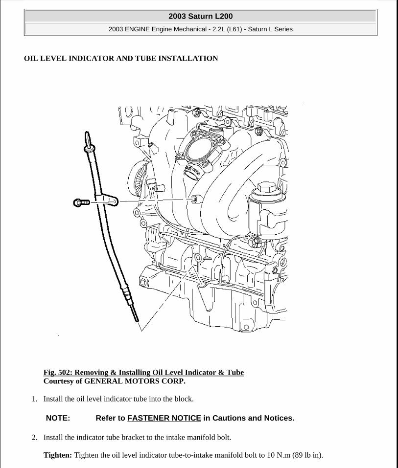
OIL LEVEL INDICATOR AND TUBE INSTALLATION
Fig. 502: Removing & Installing Oil Level Indicator & Tube Courtesy of GENERAL MOTORS CORP.
1. Install the oil level indicator tube into the block.
2. Install the indicator tube bracket to the intake manifold bolt.
Tighten: Tighten the oil level indicator tube-to-intake manifold bolt to 10 N.m (89 lb in).
NOTE: Refer to FASTENER NOTICE in Cautions and Notices.
2003 Saturn L200
2003 ENGINE Engine Mechanical - 2.2L (L61) - Saturn L Series
steve
Monday, May 09, 2011 12:52:10 PM Page 566 © 2006 Mitchell Repair Information Company, LLC.
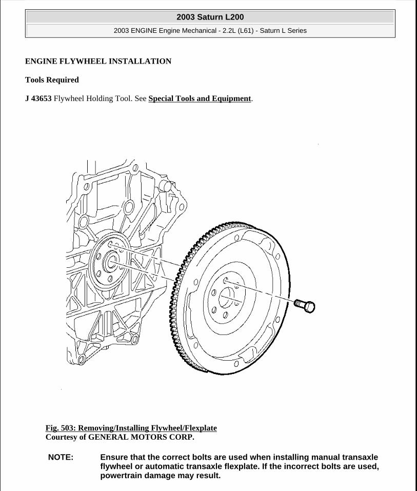
ENGINE FLYWHEEL INSTALLATION
Tools Required
J 43653 Flywheel Holding Tool. See Special Tools and Equipment.
Fig. 503: Removing/Installing Flywheel/Flexplate Courtesy of GENERAL MOTORS CORP.
NOTE: Ensure that the correct bolts are used when installing manual transaxle flywheel or automatic transaxle flexplate. If the incorrect bolts are used, powertrain damage may result.
2003 Saturn L200
2003 ENGINE Engine Mechanical - 2.2L (L61) - Saturn L Series
steve
Monday, May 09, 2011 12:52:10 PM Page 567 © 2006 Mitchell Repair Information Company, LLC.

1. Install the flywheel.
2. Install the new bolts.
3. Holding the flywheel with the J 43653 , tighten the bolts evenly. See Special Tools and Equipment.
Tighten: Tighten the flywheel bolt to 53 N.m (39 lb ft) plus 25 degrees.
DESCRIPTION AND OPERATION
ENGINE COMPONENT DESCRIPTION
Cylinder Block
The cylinder block is lost foam cast aluminum with four cylinders arranged in-line. The cylinders have cast in place iron liners. The block has five crankshaft bearings with the thrust bearing located on the second bearing from the front of the engine. The cylinder block incorporates a bedplate design that forms an upper and lower crankcase. This design promotes cylinder block rigidity and reduced noise and vibration.
Crankshaft
The crankshaft is cast nodular iron with eight counterweights. The number five counterweight is also the ignition system reluctor wheel. The main bearing journals are cross-drilled, except # 5, and the upper bearings are grooved. The crankshaft has a slip fit balance shaft drive sprocket. Number two main bearing is the thrust bearing. A harmonic damper is used to control torsional vibration.
Connecting Rod and Piston
The connecting rods are powdered metal. The connecting rod incorporates the floating piston pin. The pistons are cast aluminum. The piston rings are of a low tension type to reduce friction. The top compression ring is ductile iron with a molybdenum facing and phosphate coated sides. The second compression ring is gray iron. The oil ring is a three-piece spring construction with chromium plating.
Oil Pan
The oil pan is die cast aluminum. The oil pan includes an attachment to the transmission to provide additional structural support.
Balance Shaft Assembly
There are two block mounted balance shafts located on each side of the crankcase at the bottom of the cylinder bores. The balance shafts are driven by a single roller chain that also drives the water pump. The chain is tensioned by a hydraulic tensioner that is supplied pressure by the engine oil pump. This design promotes the maximum effectiveness of the balance shaft system and reduces noise and vibration.
NOTE: Refer to FASTENER NOTICE in Cautions and Notices.
2003 Saturn L200
2003 ENGINE Engine Mechanical - 2.2L (L61) - Saturn L Series
steve
Monday, May 09, 2011 12:52:10 PM Page 568 © 2006 Mitchell Repair Information Company, LLC.

Cylinder Head
The cylinder head is a lost foam aluminum casting. Pressed-in powdered metal valve guides and valve seat insets are used. The fuel injection nozzle is located in the intake port. The cylinder head incorporates camshaft bearing journals and camshaft bearing caps.
Valves
There are two intake and two exhaust valves per cylinder. Rotators are used on all of the intake valves. The rotators are located at the bottom of the valve spring to reduce valve train reciprocating mass. Positive valve stem seals are used on all valves.
Camshaft
Two camshafts are used, one for all intake valves, the other for all exhaust valves. The camshafts are cast iron. The intake camshaft has a pressed-in hex insert. The hex inset is used to drive the direct drive power steering pump.
Valve Lifters
The valve train uses a roller finger follower acted on by a hydraulic element adjuster. The roller finger follower reduces friction and noise.
Camshaft Cover
The camshaft cover is cast aluminum with steel crankcase ventilation baffling incorporated. The camshaft cover has mounting locations for the ignition system.
Camshaft Drive
A single row roller chain is used for camshaft drive. There is a tensioner and active guide used on the slack side of the chain to control chain motion and noise. The chain drive promotes long valvetrain life and low maintenance.
Intake and Exhaust Manifold
The intake manifold is made of composite plastic. The exhaust manifold is cast iron. The intake manifold incorporates a distribution and control system for PCV gases. The exhaust manifold is a dual plane design that promotes good low end torque and performance.
LUBRICATION DESCRIPTION
Engine Oil
At the refinery, crude oil is separated by heating and distilling it into gases, light fuels, solvents, and lubricating-oil base stocks. After being further processed, the base stocks are selectively blended and fortified with additives to produce an engine oil with the desired properties.
2003 Saturn L200
2003 ENGINE Engine Mechanical - 2.2L (L61) - Saturn L Series
steve
Monday, May 09, 2011 12:52:10 PM Page 569 © 2006 Mitchell Repair Information Company, LLC.
Engine oil, then, is a sort of prescription. It contains different ingredients to do different things. Some of these things are done by the base oil, the rest by the additives.
What is Engine Oil Supposed to Do?
It Should Lubricate
That's its primary job, to provide a separating film between moving parts and thus control friction and wear.
It Should Cool
Engine oil is the principal coolant for the pistons, main bearings, rod bearings, and camshaft. As such, it removes up to 10 percent of the total heat load generated by the engine.
It Should Seal
The sealing function is to seal combustion pressures. Even though most pistons have 2 compression rings and an oil ring, high pressure gases, containing unburnt fuel combustion products and water, can still leak into the crankcase through ring gaps and microscopic valleys in the cylinder walls. This normal leakage is called "blowby". Oil is used to fill in the valleys and reduce that leakage.
However, oil can not be expected to seal the canyons in a badly worn engine. Nor can it effectively seal a brand new engine until the parts have seated themselves. That is why oil consumption is occasionally higher for the first few thousand miles during new vehicle operation.
It Should Keep the Engine Clean
Combustion contaminants and dirt in the oil are unavoidable, but such particles tend to clump. If clumping is allowed to take place, sludge and varnish may follow.
Good engine oils are designed to prevent the particles from clumping and hold them in suspension. When the oil is drained, the suspended particles come out with it.
It Should Make Starting Easier
This is strictly a cold weather requirement. When it's freezing outside, the oil should be thin enough to give the engine a fair chance of starting. Yet as the oil gets hot and thins out, it should not become so thin that it will not lubricate or seal properly. That is what multigrade oils are for. Some of them, and all those that Saturn recommends, are designed to work in almost any temperature range.
It Should Prevent Rust and Corrosion
Metal can actually rust or corrode in oil, if the oil contains water or acids from the combustion process. A well-formulated oil protects against rusting by putting a chemical film on the metal parts, shielding them from water. It protects against acid attack by neutralizing the acid.
Additives
2003 Saturn L200
2003 ENGINE Engine Mechanical - 2.2L (L61) - Saturn L Series
steve
Monday, May 09, 2011 12:52:10 PM Page 570 © 2006 Mitchell Repair Information Company, LLC.

Additives are chemicals that give fresh engine oil its custom-made properties. Although used in small amounts, they provide a tremendous boost to the performance abilities of the engine oil. They, in fact, represent the major difference between the oils of the early 1940's and the highly advanced prescription oils of today.
Most Commonly Used Additives
Anti-wear Agents
In highly loaded parts like camshafts and valve lifters, an oil film is usually squeezed so thin it breaks. This would mean damaging metal-to-metal contact. When the oil film breaks down, these agents react chemically with the metal surfaces and from a protective coating that reduces wear.
Detergent-Dispersants
Combustion contaminants and dirt particles in the oil tend to clump, which can lead to sludge and varnish deposits. Detergent-dispersants are the additives that not only keep the engine clean but also stop such particles from massing. They work by surrounding the particles, most of which are invisible, with a shell of molecules. This action causes the imprisoned particles to repel one another. It also makes them a part of the oil, like cream is part of homogenized milk. They can not settle out on engine parts or clog oil passages.
Oxidation Inhibitors
These are additives that allow oil to lubricate when it is hot.
Oxidation is a complex chemical reaction between oil molecules and oxygen. As the operating temperature of oil goes up, so does the oil's oxidation rate. And unless the oil is heavily enriched with additives to fight oxidation, all sorts of undesirable things could happen. The worst of these is that the oil gets thicker and thicker - permanently.
Thus, a driver who waits too long between oil changes or uses low-quality oil and embarks on a cross-country trip during the summer may find the oil oxidized to a point so thick it will not drain out of the crankcase.
Rust and Corrosion Inhibitors
For every gallon of gasoline burned, about a gallon of water forms as steam. Most of the steam goes out the tailpipe, but some of it leaks as part of the blowby gases into the crankcase, where it becomes acidic. Water build-up in the oil increases with short-trip driving. If it were not for rust and corrosion inhibitors and regular oil changes, engines would wear because of that water.
V.I. Improvers
V.I. stands for viscosity index. Oils having a high viscosity index tend to thin out less when heated and thicken less when cooled. V.I. improvers are used to raise an oil's viscosity index for all-season operation. Without them there would not be multigrade oils.
Foam Inhibitors
Foam can result from air being whipped into the oil by moving engine parts, which could lead to oil loss,
2003 Saturn L200
2003 ENGINE Engine Mechanical - 2.2L (L61) - Saturn L Series
steve
Monday, May 09, 2011 12:52:10 PM Page 571 © 2006 Mitchell Repair Information Company, LLC.
hydraulic valve lifter noise, and improper cooling and lubrication. Foam inhibitors weaken the surface tension of oil, which causes the air bubbles to break more readily.
Pour Point Depressants
The pour point of an oil is the lowest temperature at which the oil will flow. Below that temperature, wax crystals form, grow, and interconnect, then solidify or freeze the oil. Pour point depressants lower this freezing temperature by coating the wax crystals as they form, thereby checking crystal growth.
Friction Modifiers
These are the newest members of the family of additives in modern oils. They further reduce surface friction between moving parts. Friction modifiers, along with low viscosity, make "Energy Conserving" and similarly labeled oils possible. Such oils can increase a vehicle's fuel economy by several percent.
Oil Container Labels
The American Petroleum Institute (API) logo is a circle divided into 3 sections. The top half of the circle is the "API Service" section, which indicates the oil's degree of fuel efficiency. The center of the circle is the "Energy Conservation" section, which indicates the oil's degree of fuel efficiency. The center of the circle is the "Viscosity" section, which is used to indicate the viscosity of the oil. The oil container should have a "Starburst" label instead of the doughnut shaped symbol.
2003 Saturn L200
2003 ENGINE Engine Mechanical - 2.2L (L61) - Saturn L Series
steve
Monday, May 09, 2011 12:52:10 PM Page 572 © 2006 Mitchell Repair Information Company, LLC.

Fig. 504: Identifying American Petroleum Institute Logo Courtesy of GENERAL MOTORS CORP.
Multi-Grade Oils
These oils make seasonal changing unnecessary. They contain viscosity-index improvers that enable each oil to exhibit suitable flow properties at both ends of the thermometer.
They have labels like SAE 5W-30, 10W-30, or 15W-40. Some may have labels like SAE 5W-10W-20W-30, in this case, just ignore the middle numbers and read the oil as SAE 5W-30.
Oil Can Save You Gas
2003 Saturn L200
2003 ENGINE Engine Mechanical - 2.2L (L61) - Saturn L Series
steve
Monday, May 09, 2011 12:52:10 PM Page 573 © 2006 Mitchell Repair Information Company, LLC.

Many factors are involved in determining the overall fuel economy obtained when driving a vehicle. One of the factors is the fuel efficiency of the engine oil being used.
In addition to being rated on the basis of their performance and viscosity, oils are rated on their ability to reduce the amount of fuel consumed during driving. Oils are rated against a reference oil in a standard engine test much like the ones described earlier in the Oil Performance Ratings section.
In this particular test, the fuel economy is measured and compared with that of a reference oil. If the tested oil provides at least 1.5 percent better economy than the reference oil, it is labeled "Energy Conserving II". These energy conserving designations are indicated on the lower half of the API logo to indicate fuel efficiency. Energy Conserving II oils should provide the best fuel efficiency, by the lease fuel efficient oils, ones that do not contain either designation.
Synthetic Oils
Compared with conventional motor oils, the synthetics involve different chemical processes and ingredient percentages. However, the base stock still comes from crude petroleum, and the additives are virtually the same as those commonly used.
From a performance standpoint, they work well, especially for engine start-up at very low temperatures. But, based on all the information, synthetic oils can not be left in an engine any longer than conventional oils. Extended use is the principal claim of synthetics. They can be used, but must have the right service category, viscosity grade, and fuel efficiency designation for the vehicle. The oil must be changed as specified in your owner's manual.
A second category, beginning with the letter C, also exists. These oils, CC, CD, CE, etc., are intended for diesels, like in trucks and bulldozers, and by themselves are not suitable for gasoline engines.
Viscosity
Viscosity is resistance to flow. Thick oils have a high resistance and, therefore, a high viscosity. Thin oils have a low resistance and, by the same token, a low viscosity.
A Society of Automotive Engineers (SAE) number that appears in the center of the API logo. The SAE number defines the viscosity grading of oils, both single-grade and multigrade.
Single-Grade Oils
"Single-grade" refers to oils whose labeled viscosity applies at one temperature only. In general, single-grade oils indicated their viscosity by a single number, for example SAE 10W or SAE30. The higher the number, the thicker the oil. The W, for winter, tells you that the labeled viscosity applies at a sub-freezing temperature. Other wise it applies at 100°C (212°F).
Most non-W oils thicken when the temperature drops, which makes cold-engine starting very difficult or downright impossible. Many W oils also thin out too much in warmer weather, which hurts their ability to lubricate and seal.
Oil Filter
2003 Saturn L200
2003 ENGINE Engine Mechanical - 2.2L (L61) - Saturn L Series
steve
Monday, May 09, 2011 12:52:10 PM Page 574 © 2006 Mitchell Repair Information Company, LLC.
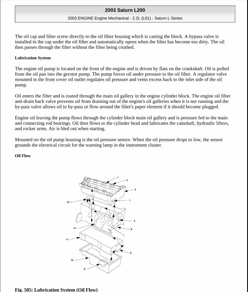
The oil cap and filter screw directly to the oil filter housing which is casting the block. A bypass valve is installed in the cap under the oil filter and automatically opens when the filter has become too dirty. The oil then passes through the filter without the filter being crushed.
Lubrication System
The engine oil pump is located on the front of the engine and is driven by flats on the crankshaft. Oil is pulled from the oil pan into the gerotor pump. The pump forces oil under pressure to the oil filter. A regulator valve mounted in the front cover oil outlet regulates oil pressure and vents excess back to the inlet side of the oil pump.
Oil enters the filter and is routed through the main oil gallery in the engine cylinder block. The engine oil filter anti-drain back valve prevents oil from draining out of the engine's oil galleries when it is not running and the by-pass valve allows oil to by-pass or flow around the filter's paper element if it should become plugged.
Engine oil leaving the pump flows through the cylinder block main oil gallery and is pressure fed to the main and connecting rod bearings. Oil then flows to the cylinder head and lubricates the camshaft, hydraulic lifters, and rocker arms. Air is bled out when starting.
Mounted on the oil pump housing is the oil pressure sensor. When the oil pressure drops to low, the sensor grounds the electrical circuit for the warning lamp in the instrument cluster.
Oil Flow
Fig. 505: Lubrication System (Oil Flow)
2003 Saturn L200
2003 ENGINE Engine Mechanical - 2.2L (L61) - Saturn L Series
steve
Monday, May 09, 2011 12:52:10 PM Page 575 © 2006 Mitchell Repair Information Company, LLC.

Courtesy of GENERAL MOTORS CORP.
Callouts For Fig. 505
Oil is applied under pressure to the crankshaft, connecting rods, balance shaft assembly, camshaft bearing surfaces, valve lifters, and timing chain hydraulic tensioner. All other moving parts are lubricated by gravity flow or splash. Oil enters the gerotor type oil pump through a fixed inlet screen. The oil pump is driven by the crankshaft. The oil pump body is within the engine front cover. The pressurized oil from the pump passes through the oil filter. The oil filter is located on the right front side of the engine block.
The oil filter is housed in a casting that is integrated with the engine block. The oil filter is a disposable cartridge type. A by-pass valve in the engine block allows continuous oil flow in case the oil filter should become restricted. Oil then enters the gallery when it is distributed to the balance shafts, crankshaft, and camshafts. The connecting rod bearings are oiled by constant oil flow passages through the crankshaft connecting the main journals to the rod journals. A groove around each main bearing furnishes oil to the drilled crankshaft passages.
An oil cooling hole, which indexes once each revolution with the connecting rod oil feed hole, is drilled in the connecting bearing surface. The pressurized oil passes through the oil flow check valve into the cylinder head and then into each camshaft feed gallery. Cast passages feed each hydraulic element adjuster and drilled passages feed each camshaft bearing surface. An engine oil pressure switch or sensor is installed at the end. Oil returns to the oil pan through passages cast into the cylinder head. The timing chain lubrication drains directly into the oil pan.
SEPARATING PARTS
Callout Component Name1 Hydraulic Lifter2 Cam Bearing3 Cylinder Head4 Timing Chain Tensioner5 Cam Drive Chain Oil Nozzle6 Crankshaft Bearing7 Balance Shaft Chain Tensioner8 Oil Pump9 Oil Pick Up10 Oil Pan11 Bedplate12 Balance Shaft Bearings13 Oil Filter
IMPORTANT: Disassembly of the piston, press fit design piston pin, and connecting rod may create scoring or damage to the piston pin and piston pin bore. If the piston, pin, and connecting rod have been disassembled, replace the components as an assembly.
2003 Saturn L200
2003 ENGINE Engine Mechanical - 2.2L (L61) - Saturn L Series
steve
Monday, May 09, 2011 12:52:10 PM Page 576 © 2006 Mitchell Repair Information Company, LLC.
Separate, mark, or organize the following components:
Piston and the piston pin
Piston to the specific cylinder bore
Piston rings to the piston
Connecting rod to the crankshaft journal
Connecting rod to the bearing cap
A paint stick or etching/engraving type tool are recommended. Stamping the connecting rod or cap near the bearing bore may affect component geometry.
Crankshaft main and connecting rod bearings
Camshaft and valve lifters
Valve lifters, lifter guides, pushrods and rocker arm assemblies
Valve to the valve guide
Valve spring and shim to the cylinder head location
Engine block main bearing cap location and direction
Oil pump drive and driven gears
REPLACING ENGINE GASKETS
Gasket Reuse and Applying Sealants
Do not reuse any gasket unless specified.
Gaskets that can be reused will be identified in the service procedure.
Do not apply sealant to any gasket or sealing surface unless called out in the service information.
Separating Components
Use a rubber mallet to separate components.
Bump the part sideways to loosen the components.
Bumping should be done at bends or reinforced areas to prevent distortion of parts.
Cleaning Gasket Surfaces
Remove all gasket and sealing material from the part using a wood or plastic gasket scraper make from aluminum surfaces.
Many internal engine components will develop specific wear patterns on their friction surfaces.
When disassembling the engine, internal components MUST be separated, marked, or organized in a way to ensure installation to their original location and position.
2003 Saturn L200
2003 ENGINE Engine Mechanical - 2.2L (L61) - Saturn L Series
steve
Monday, May 09, 2011 12:52:10 PM Page 577 © 2006 Mitchell Repair Information Company, LLC.

Care must be used to avoid gouging or scraping the sealing surfaces.
Do not use any other method or technique to remove sealant or gasket material from a part.
Do not use abrasive pads, sand paper, or power tools to clean the gasket surfaces.
These methods of cleaning can cause damage to the component sealing surfaces.
Abrasive pads also produce a fine grit that the oil filter cannot remove from the oil.
This grit is abrasive and has been known to cause internal engine damage.
Assembling Components
When assembling components, use only the sealant specified or equivalent in the service procedure.
Sealing surfaces should be clean and free of debris or oil.
Specific components such as crankshaft oil seals or valve stem oil seals may require lubrication during assembly.
Components requiring lubrication will be identified in the service procedure.
When applying sealant to a component, apply the amount specified in the service procedure.
Do not allow the sealant to enter into any blind threaded holes, as it may prevent the bolt from clamping properly or cause component damage when tightened.
Tighten bolts to specifications. Do not overtighten.
USE OF ROOM TEMPERATURE VULCANIZING (RTV) AND ANAEROBIC SEALER
Pipe Joint Compound
Pipe joint compound is a pliable sealer that does not completely harden. This type sealer is used where two non-rigid parts (such as the oil pan and the engine block) are assembled together.
Do not use pipe joint compound in areas where extreme temperatures are expected. These areas include: exhaust manifold, head gasket, or other surfaces where gasket eliminator is specified.
Follow all safety recommendations and directions that are on the container.
Apply the pipe joint compound to a clean surface. Use a bead size or quantity as specified in the procedure. Run the bead to the inside of any bolt holes. Do not allow the sealer to enter any blind threaded holes, as it may prevent the bolt from clamping properly or cause component damage when the bolt is tightened.
Apply a continuous bead of pipe joint compound to one sealing surface. Sealing surfaces to be resealed must be clean and dry.
Tighten the bolts to specifications. Do not overtighten.
RTV Sealer
IMPORTANT: Three types of sealer are commonly used in engines. These are RTV sealer, anaerobic gasket eliminator sealer, and pipe joint compound. The correct sealer and amount must be used in the proper location to prevent oil leaks. DO NOT interchange the three types of sealers. Use only the specific sealer or the equivalent as recommended in the service procedure.
2003 Saturn L200
2003 ENGINE Engine Mechanical - 2.2L (L61) - Saturn L Series
steve
Monday, May 09, 2011 12:52:10 PM Page 578 © 2006 Mitchell Repair Information Company, LLC.

Room Temperature Vulcanizing (RTV) sealant hardens when exposed to air. This type sealer is used where two rigid parts (such as the lower crankcase and the engine block) are assembled together.
Do not use Room Temperature Vulcanizing (RTV) sealant in areas where extreme temperatures are expected. These areas include: exhaust manifold, head gasket, or other surfaces where a gasket eliminator is specified.
Follow all safety recommendations and directions that are on the container.
Apply RTV to a clean surface. Use a bead size as specified in the procedure. Run the bead to the inside of any bolt holes. Do not allow the sealer to enter any blind threaded holes, as it may prevent the bolt from clamping properly or cause damage when the bolt is tightened.
Assemble components while RTV is still wet (within 3 minutes). Do not wait for RTV to skin over.
Tighten bolts to specifications. Do not overtighten.
Anaerobic Sealer
Anaerobic gasket eliminator hardens in the absence of air. This type sealer is used where two rigid parts (such as castings) are assembled together. When two rigid parts are disassembled and no sealer or gasket is readily noticeable, the parts were probably assembled using a gasket eliminator.
Follow all safety recommendations and directions that are on the container. To remove the sealant or the gasket material, refer to Replacing Engine Gaskets procedure in this service manual.
Apply a continuous bead of gasket eliminator to one flange. Surfaces to be resealed must be clean and dry.
Spread the sealer evenly with your finger to get a uniform coating on the sealing surface.
Do not allow the sealer to enter any blind threaded holes, as it may prevent the bolt from clamping properly or cause damage when tightened.
Tighten bolts to specifications. Do not overtighten.
After properly tightening the fasteners, remove the excess sealer from the outside of the joint.
Separating Parts
Separate, mark, or organize the following components:
Piston and the piston pin
IMPORTANT: Anaerobic sealed joints that are partially torqued and allowed to cure more than five minutes may result in incorrect shimming and sealing of the joint. Do not allow the sealer to enter any blind threaded holes, as it may prevent the bolt from seating properly or cause damage when the bolt is tightened.
IMPORTANT: Many internal engine components will develop specific wear patterns on their friction surfaces. When disassembling the engine, internal components MUST be separated, marked, or organized in a way to ensure reinstallation to their original location and position.
2003 Saturn L200
2003 ENGINE Engine Mechanical - 2.2L (L61) - Saturn L Series
steve
Monday, May 09, 2011 12:52:10 PM Page 579 © 2006 Mitchell Repair Information Company, LLC.
Piston to the specific cylinder bore
Piston rings to the piston
Connecting rod to the crankshaft journal
Connecting rod to the bearing cap
A paint stick or etching/engraving type tool are recommended. Stamping the connecting rod or cap near the bearing bore may affect component geometry.
Crankshaft main and connecting rod bearings
Camshaft and valve lifters
Valve lifters, guides, pushrods, pivot supports and rocker arms
Valve to the valve guide
Valve spring and shim to the cylinder head location
Engine block main bearing cap location and direction
Oil pump drive and driven gears
TOOLS AND EQUIPMENT
Special tools are listed and illustrated throughout this section with a complete listing at the beginning of the section. These tools (or their equivalents) are specially designed to quickly and safely accomplish the operations for which they are intended. The use of these special tools will also minimize possible damage to engine components. Some precision measuring tools are required for inspection of certain critical components. Torque wrenches and a torque angle meter are necessary for the proper tightening of various fasteners.
To properly service the engine assembly, the following items should be readily available:
Approved eye protection and safety gloves
A clean, well-lit, work area
A suitable parts cleaning tank
A compressed air supply
Trays or storage containers to keep parts and fasteners organized
An adequate set of hand tools
Approved engine repair stand
An approved engine lifting device that will adequately support the weight of the components
SPECIAL TOOLS AND EQUIPMENT
SPECIAL TOOLS
Special Tools Illustration Tool Number/ Description
2003 Saturn L200
2003 ENGINE Engine Mechanical - 2.2L (L61) - Saturn L Series
steve
Monday, May 09, 2011 12:52:10 PM Page 580 © 2006 Mitchell Repair Information Company, LLC.

J 7872 Magnetic Base Dial Indicator
J 8062 Valve Spring Compressor - Head Off
J 9666 Valve Spring Tester
J 35268-A Camshaft Front Main Seal Installer
J 35667-A Cylinder Head Leakdown Tester
2003 Saturn L200
2003 ENGINE Engine Mechanical - 2.2L (L61) - Saturn L Series
steve
Monday, May 09, 2011 12:52:10 PM Page 581 © 2006 Mitchell Repair Information Company, LLC.

J 35749 Oil Pressure Socket
J 36017 Valve Guide Seal Remover
J 36660-A Torque Angle Meter
J 37088-A Fuel Line Disconnect Set
2003 Saturn L200
2003 ENGINE Engine Mechanical - 2.2L (L61) - Saturn L Series
steve
Monday, May 09, 2011 12:52:10 PM Page 582 © 2006 Mitchell Repair Information Company, LLC.

J 38122 Crankshaft Pulley Holder
J 38188 Cylinder Head Broken Bolt Extractor Kit
J 39194-C O2 Sensor Wrench
J 41545 Transaxle Range Switch Alignment Tool
J 41742 Connecting Rod Guide Pin
2003 Saturn L200
2003 ENGINE Engine Mechanical - 2.2L (L61) - Saturn L Series
steve
Monday, May 09, 2011 12:52:10 PM Page 583 © 2006 Mitchell Repair Information Company, LLC.
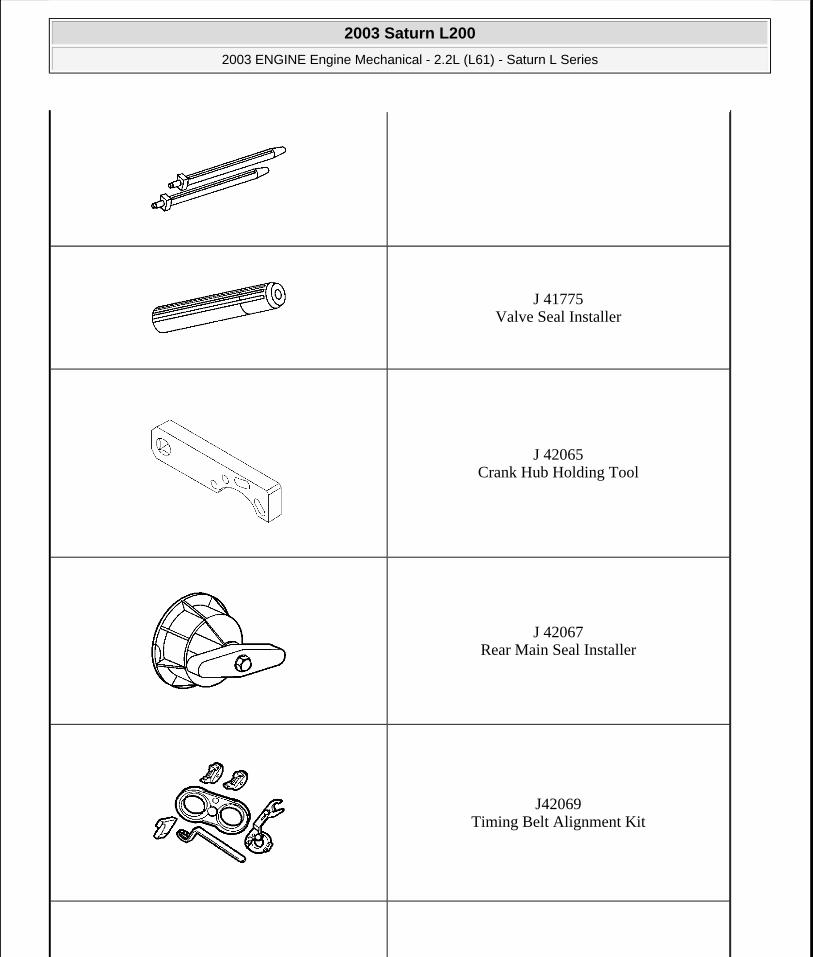
J 41775 Valve Seal Installer
J 42065 Crank Hub Holding Tool
J 42067 Rear Main Seal Installer
J42069 Timing Belt Alignment Kit
2003 Saturn L200
2003 ENGINE Engine Mechanical - 2.2L (L61) - Saturn L Series
steve
Monday, May 09, 2011 12:52:10 PM Page 584 © 2006 Mitchell Repair Information Company, LLC.
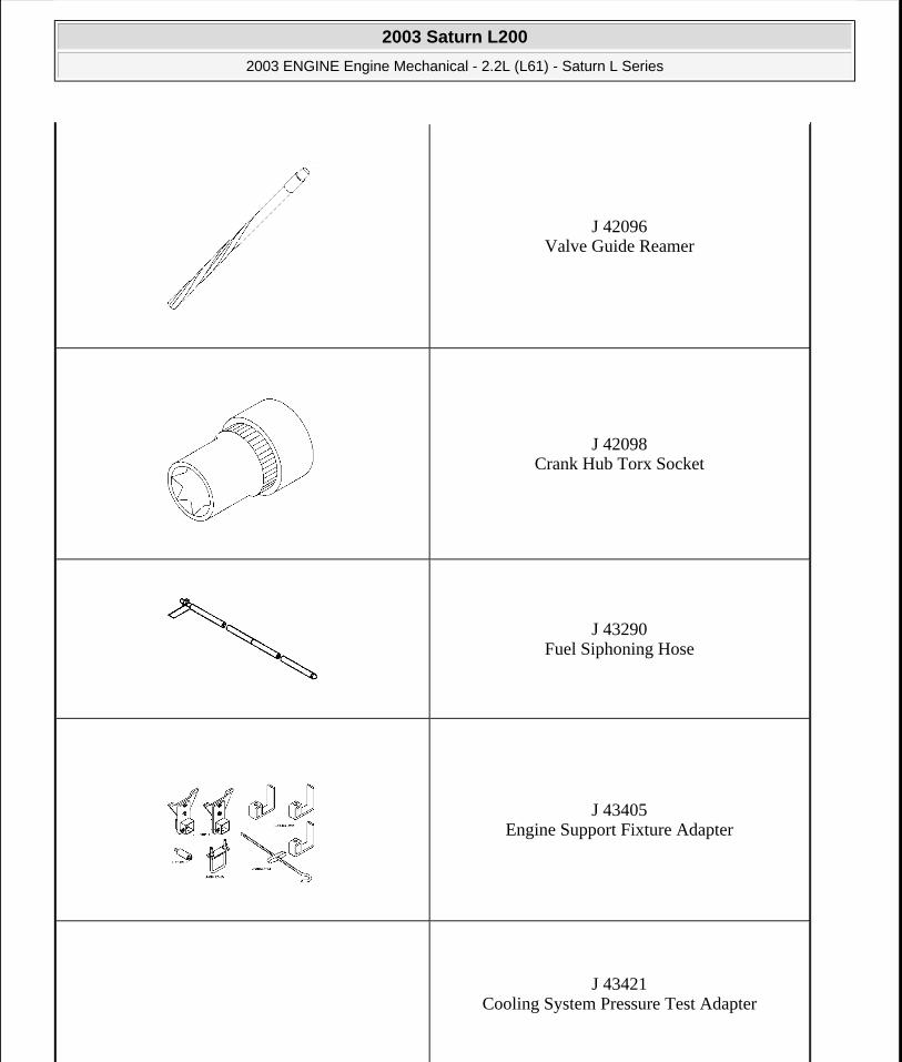
J 42096 Valve Guide Reamer
J 42098 Crank Hub Torx Socket
J 43290 Fuel Siphoning Hose
J 43405 Engine Support Fixture Adapter
J 43421 Cooling System Pressure Test Adapter
2003 Saturn L200
2003 ENGINE Engine Mechanical - 2.2L (L61) - Saturn L Series
steve
Monday, May 09, 2011 12:52:10 PM Page 585 © 2006 Mitchell Repair Information Company, LLC.

J 43628 Frame Alignment Fixture
J 43649 Valve Spring Compressor
J 43650 Balance Shaft Bearing Remover/Installer
2003 Saturn L200
2003 ENGINE Engine Mechanical - 2.2L (L61) - Saturn L Series
steve
Monday, May 09, 2011 12:52:10 PM Page 586 © 2006 Mitchell Repair Information Company, LLC.
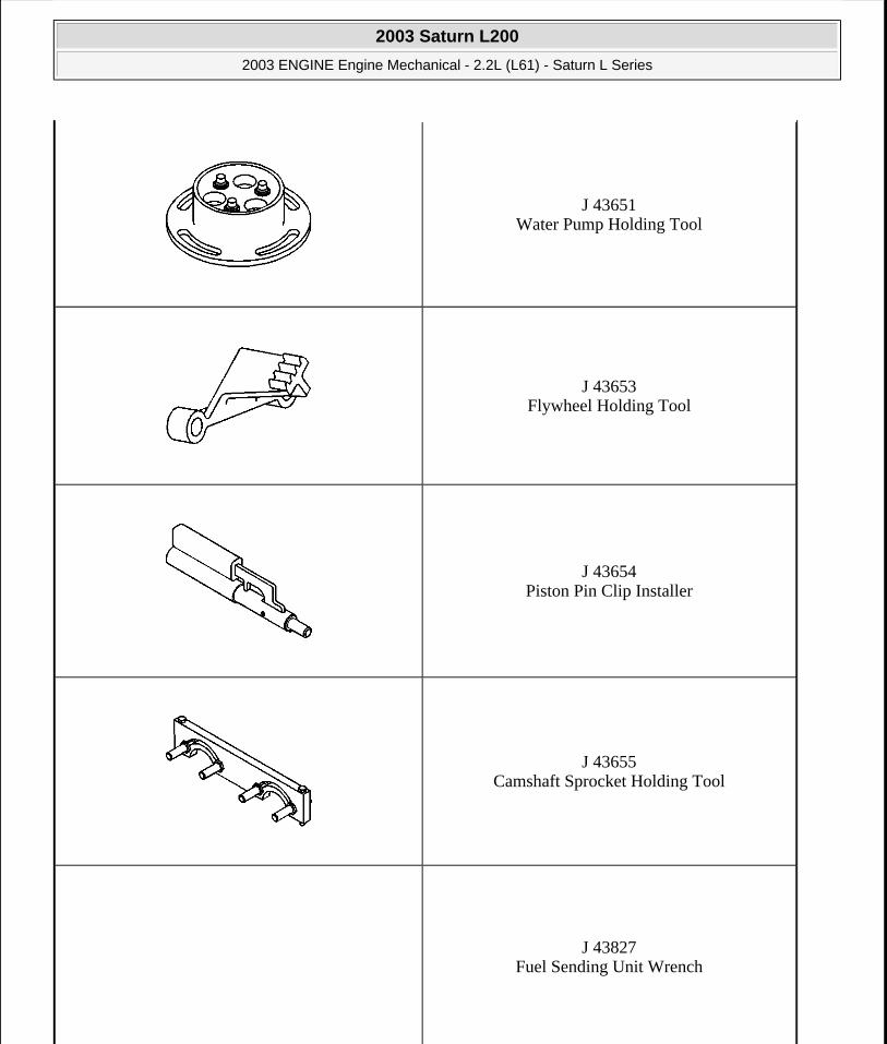
J 43651 Water Pump Holding Tool
J 43653 Flywheel Holding Tool
J 43654 Piston Pin Clip Installer
J 43655 Camshaft Sprocket Holding Tool
J 43827 Fuel Sending Unit Wrench
2003 Saturn L200
2003 ENGINE Engine Mechanical - 2.2L (L61) - Saturn L Series
steve
Monday, May 09, 2011 12:52:10 PM Page 587 © 2006 Mitchell Repair Information Company, LLC.

J 43914 Clamp Pliers, Universal
J 43936 Fuel Pressure Adapter Cap
J 43953 Piston Ring Compressor
2003 Saturn L200
2003 ENGINE Engine Mechanical - 2.2L (L61) - Saturn L Series
steve
Monday, May 09, 2011 12:52:10 PM Page 588 © 2006 Mitchell Repair Information Company, LLC.

J 43963 Valve Spring Compressor (Off Vehicle)
J 44015 Steering Linkage Installer
J 44628 Bearing Bridge Sleeve Wrench
J 44953 Oil Pressure Fitting
J 45027 Tensioner Tool
2003 Saturn L200
2003 ENGINE Engine Mechanical - 2.2L (L61) - Saturn L Series
steve
Monday, May 09, 2011 12:52:10 PM Page 589 © 2006 Mitchell Repair Information Company, LLC.

SA9101E Piston Pin Retainer/Replacer
SA9102-E Valve Seal Remover/Replacer
SA9105-E Engine Support Fixture (3 Bar)
2003 Saturn L200
2003 ENGINE Engine Mechanical - 2.2L (L61) - Saturn L Series
steve
Monday, May 09, 2011 12:52:10 PM Page 590 © 2006 Mitchell Repair Information Company, LLC.

SA91101NE Feeler Gauge Set
SA9123E Gasket Seal Cutter
SA9124E Regulator Valve Remover/Replacer
SA9127E Gauge Bar Set
2003 Saturn L200
2003 ENGINE Engine Mechanical - 2.2L (L61) - Saturn L Series
steve
Monday, May 09, 2011 12:52:10 PM Page 591 © 2006 Mitchell Repair Information Company, LLC.
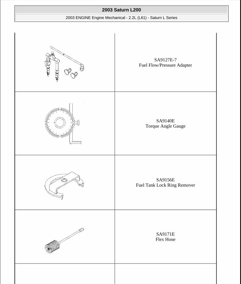
SA9127E-7 Fuel Flow/Pressure Adapter
SA9140E Torque Angle Gauge
SA9156E Fuel Tank Lock Ring Remover
SA9171E Flex Hone
2003 Saturn L200
2003 ENGINE Engine Mechanical - 2.2L (L61) - Saturn L Series
steve
Monday, May 09, 2011 12:52:10 PM Page 592 © 2006 Mitchell Repair Information Company, LLC.
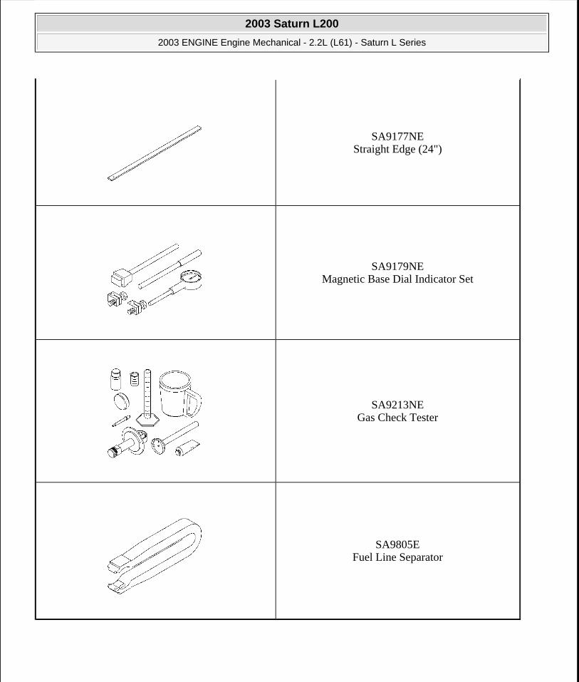
SA9177NE Straight Edge (24")
SA9179NE Magnetic Base Dial Indicator Set
SA9213NE Gas Check Tester
SA9805E Fuel Line Separator
2003 Saturn L200
2003 ENGINE Engine Mechanical - 2.2L (L61) - Saturn L Series
steve
Monday, May 09, 2011 12:52:11 PM Page 593 © 2006 Mitchell Repair Information Company, LLC.