Embed Size (px)
Citation preview
Node Design Phase 1 Presentation
Presented by SD1/SD2/IV/SA

Our Goal
Node Design Pattern and substantiating theory.
Utilised for the design of all the Nodes throughout the chassis.
Initial Node used for Design
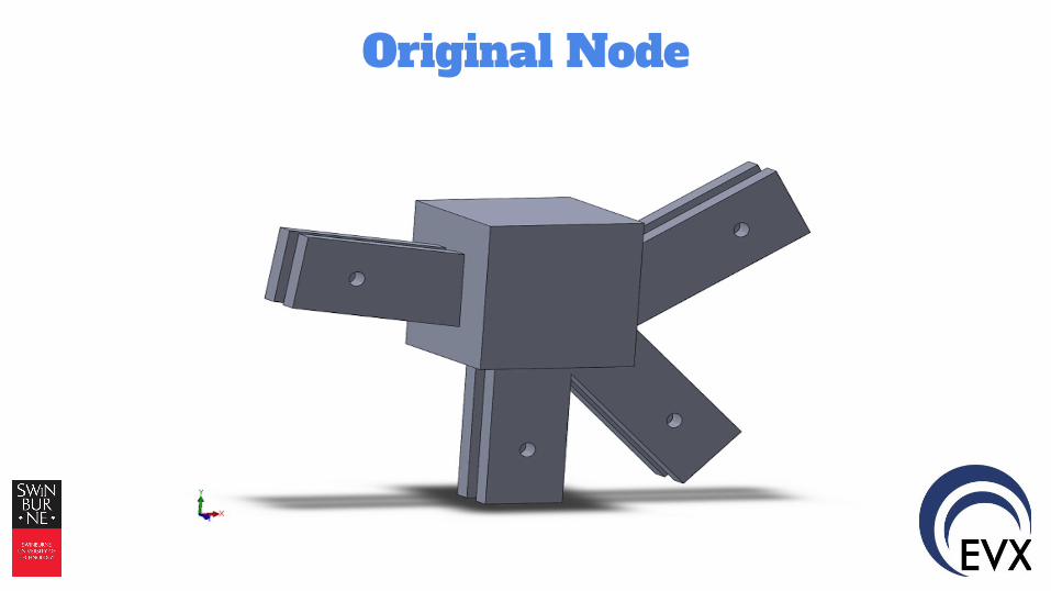
Original Node
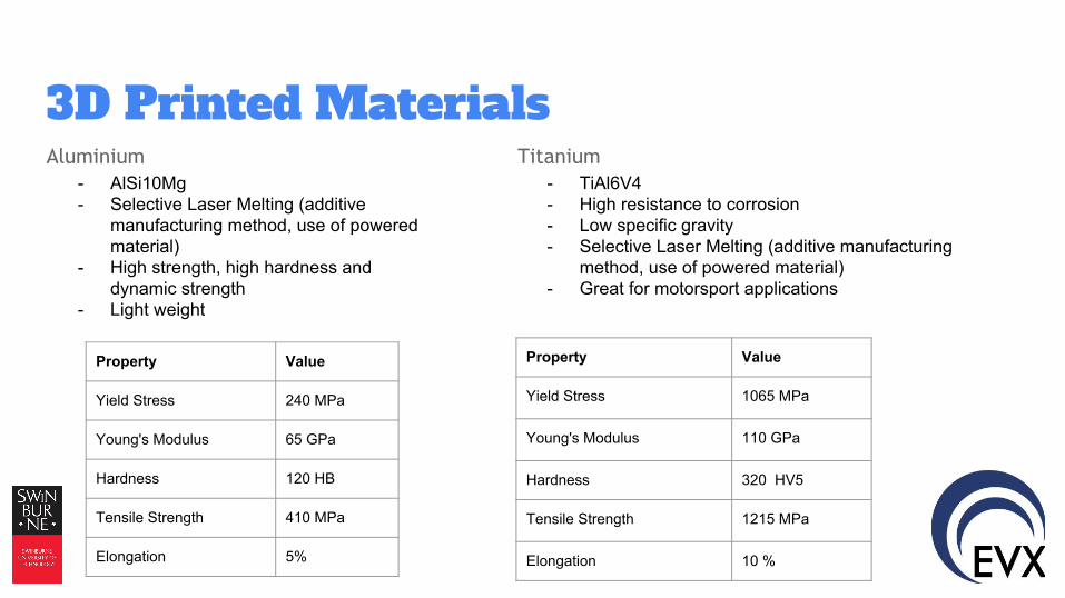
3D Printed MaterialsAluminium Titanium
- AlSi10Mg- Selective Laser Melting (additive
manufacturing method, use of powered material)
- High strength, high hardness and dynamic strength
- Light weight
Property Value
Yield Stress 240 MPa
Young's Modulus 65 GPa
Hardness 120 HB
Tensile Strength 410 MPa
Elongation 5%
- TiAl6V4- High resistance to corrosion- Low specific gravity - Selective Laser Melting (additive manufacturing
method, use of powered material)- Great for motorsport applications
Property Value
Yield Stress 1065 MPa
Young's Modulus 110 GPa
Hardness 320 HV5
Tensile Strength 1215 MPa
Elongation 10 %

Integrated Node Design

Spherical Node Design

Tubular Node Design

Lattice Node Design

Design Inspiration &
Genisis
Lego: Locking Eyelet

Modular Eyelet Node Design
Part A Part B
Coupling Pin
Collar

Modular Eyelet Node Design
Assembly Options

Benefits of Modular Eyelet
Node Design● Reduced Number of components
● Less Materials = Reduction in weight
● Reduction in weakness points (less thin members)
● Modularisation means less print patterns
● Easier assembly
● Looks slick

Extensions of Modular Eyelet
Node Design
● Locking teeth between surfaces
● Securing end-cap positions with locking pins
● Addition of a design for irregularly angled joints
● Hollow out solid material within stress / strain limits
● Determine best method for securing frame rods
within end-caps

What’s Next?
● Stress strain Testing
● Investigate concept extensions
● Investigate material options and printing techniques
● Incorporate into frame design file and test rigidity
● Iterate
● Iterate
● Iterate

Questions?