Embed Size (px)
Citation preview

Welcome to the growing family of new NISSANowners. This vehicle is delivered to you withconfidence. It was produced using the latesttechniques and strict quality control.
This manual was prepared to help you under-stand the operation and maintenance of yourvehicle so that you may enjoy many miles (kilome-ters) of driving pleasure. Please read through thismanual before operating your vehicle.
A separate Warranty Information Bookletexplains details about the warranties cov-ering your vehicle. The “NISSAN Serviceand Maintenance Guide” explains detailsabout maintaining and servicing your ve-hicle. Additionally, a separate CustomerCare/Lemon Law Booklet (U.S. only) willexplain how to resolve any concerns youmay have with your vehicle, as well asclarify your rights under your state’s lemonlaw.
Your NISSAN dealership knows your vehiclebest. When you require any service or have anyquestions, they will be glad to assist you with theextensive resources available to them.
Before driving your vehicle please read this Own-er’s Manual carefully. This will ensure familiaritywith controls and maintenance requirements, as-sisting you in the safe operation of your vehicle.
WARNING
IMPORTANT SAFETY INFORMATION RE-MINDERS FOR SAFETY!
Follow these important driving rules tohelp ensure a safe and complete trip foryou and your passengers!
● NEVER drive under the influence of al-cohol or drugs.
● ALWAYS observe posted speed limitsand never drive too fast for conditions.
● ALWAYS use your seat belts and appro-priate child restraint systems. Preteenchildren should be seated in the rearseat.
● ALWAYS provide information about theproper use of vehicle safety features toall occupants of the vehicle.
● ALWAYS review this owner’s manual forimportant safety information.
MODIFICATION OF YOUR VEHICLE
This vehicle should not be modified.Modification could affect itsperformance, safety or durability, andmay even violate governmentalregulations. In addition, damage or per-formance problems resulting frommodifications may not be covered un-der NISSAN warranties.
FOREWORD READ FIRST—THEN DRIVE SAFELY
Z REVIEW COPY:—2004 Maxima (max)Owners Manual (owners)—USA English (nna)10/07/03—tbrooks X
The inside pages of this manual containa minimum of 50% recycled fibers,including 10% post-consumer fibers.
This manual includes information for all optionsavailable on this model. Therefore, you may findsome information that does not apply to yourvehicle.
All information, specifications and illustrations inthis manual are those in effect at the time ofprinting. NISSAN reserves the right to changespecifications or design without notice and with-out obligation.
IMPORTANT INFORMATION ABOUTTHIS MANUALYou will see various symbols in this manual. Theyare used in the following ways:
WARNING
This is used to indicate the presence of ahazard that could cause death or seriouspersonal injury. To avoid or reduce therisk, the procedures must be followedprecisely.
CAUTION
This is used to indicate the presence of ahazard that could cause minor or moder-ate personal injury or damage to your ve-hicle. To avoid or reduce the risk, the pro-cedures must be followed carefully.
If you see this symbol, it means “Do not do this”or “Do not let this happen.”
If you see a symbol similar to these in an illustra-tion, it means the arrow points to the front of thevehicle.
Arrows in an illustration that are similar to theseindicate movement or action.
Arrows in an illustration that are similar to thesecall attention to an item in the illustration.
CALIFORNIA PROPOSITION 65WARNING
WARNING
Engine exhaust, some of its constituents,and certain vehicle components containor emit chemicals known to the State ofCalifornia to cause cancer and birth de-fects or other reproductive harm. In addi-tion, certain fluids contained in vehiclesand certain products of component wearcontain or emit chemicals known to theState of California to cause cancer andbirth defects or other reproductive harm.
© 2003 NISSAN NORTH AMERICA, INC.GARDENA, CALIFORNIA
All rights reserved. No part of this Owner’sManual may be reproduced or stored in a retrievalsystem, or transmitted in any form, or by anymeans, electronic, mechanical, photocopying,recording or otherwise, without the prior writtenpermission of Nissan North America, Inc., Gar-dena, California.
APD1005
WHEN READING THE MANUAL
Z REVIEW COPY:—2004 Maxima (max)Owners Manual (owners)—USA English (nna)10/07/03—tbrooks X
The inside pages of this manual containa minimum of 50% recycled fibers,including 10% post-consumer fibers.
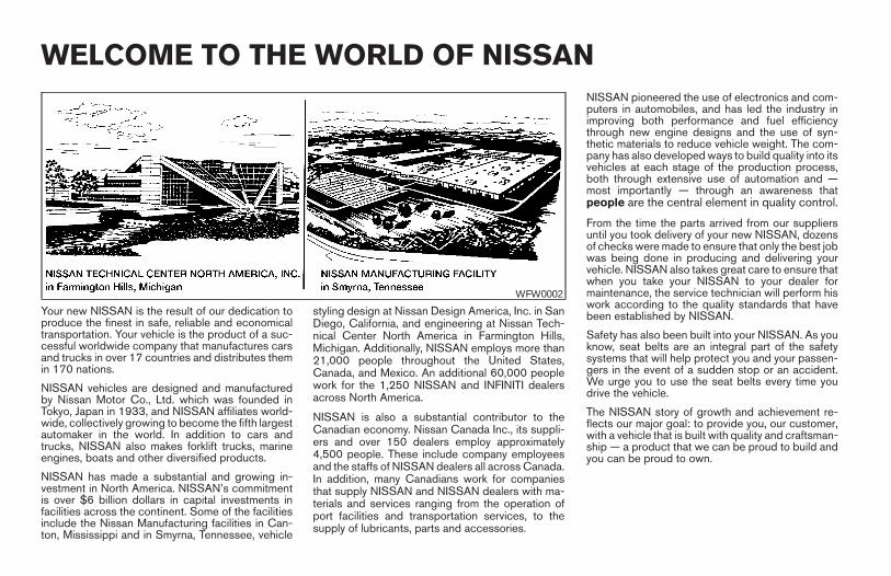
Your new NISSAN is the result of our dedication toproduce the finest in safe, reliable and economicaltransportation. Your vehicle is the product of a suc-cessful worldwide company that manufactures carsand trucks in over 17 countries and distributes themin 170 nations.
NISSAN vehicles are designed and manufacturedby Nissan Motor Co., Ltd. which was founded inTokyo, Japan in 1933, and NISSAN affiliates world-wide, collectively growing to become the fifth largestautomaker in the world. In addition to cars andtrucks, NISSAN also makes forklift trucks, marineengines, boats and other diversified products.
NISSAN has made a substantial and growing in-vestment in North America. NISSAN’s commitmentis over $6 billion dollars in capital investments infacilities across the continent. Some of the facilitiesinclude the Nissan Manufacturing facilities in Can-ton, Mississippi and in Smyrna, Tennessee, vehicle
styling design at Nissan Design America, Inc. in SanDiego, California, and engineering at Nissan Tech-nical Center North America in Farmington Hills,Michigan. Additionally, NISSAN employs more than21,000 people throughout the United States,Canada, and Mexico. An additional 60,000 peoplework for the 1,250 NISSAN and INFINITI dealersacross North America.
NISSAN is also a substantial contributor to theCanadian economy. Nissan Canada Inc., its suppli-ers and over 150 dealers employ approximately4,500 people. These include company employeesand the staffs of NISSAN dealers all across Canada.In addition, many Canadians work for companiesthat supply NISSAN and NISSAN dealers with ma-terials and services ranging from the operation ofport facilities and transportation services, to thesupply of lubricants, parts and accessories.
NISSAN pioneered the use of electronics and com-puters in automobiles, and has led the industry inimproving both performance and fuel efficiencythrough new engine designs and the use of syn-thetic materials to reduce vehicle weight. The com-pany has also developed ways to build quality into itsvehicles at each stage of the production process,both through extensive use of automation and —most importantly — through an awareness thatpeople are the central element in quality control.
From the time the parts arrived from our suppliersuntil you took delivery of your new NISSAN, dozensof checks were made to ensure that only the best jobwas being done in producing and delivering yourvehicle. NISSAN also takes great care to ensure thatwhen you take your NISSAN to your dealer formaintenance, the service technician will perform hiswork according to the quality standards that havebeen established by NISSAN.
Safety has also been built into your NISSAN. As youknow, seat belts are an integral part of the safetysystems that will help protect you and your passen-gers in the event of a sudden stop or an accident.We urge you to use the seat belts every time youdrive the vehicle.
The NISSAN story of growth and achievement re-flects our major goal: to provide you, our customer,with a vehicle that is built with quality and craftsman-ship — a product that we can be proud to build andyou can be proud to own.
WFW0002
WELCOME TO THE WORLD OF NISSAN
Z REVIEW COPY:—2004 Maxima (max)Owners Manual (owners)—USA English (nna)10/07/03—tbrooks X
NISSAN CARES . . .
Both NISSAN and your NISSAN dealer are dedicated to serving all your automotive needs. Your satisfaction with your vehicle and your NISSAN dealer areour primary concerns. Your NISSAN dealer is always available to assist you with all your automobile sales and service needs.
However, if there is something that your NISSANdealer cannot assist you with or you would like toprovide NISSAN directly with comments or ques-tions, please contact the NISSAN Consumer AffairsDepartment using our toll-free number:
For U.S. mainland and Alaska customers1-800-NISSAN-1(1-800-647-7261)
For Hawaii customers1-808-836-0888 (Oahu Number)
For Canadian customers1-800-387-0122
The Consumer Affairs Department will ask for thefollowing information:
– Your name, address, and telephone number
– Vehicle identification number (attached to thetop of the instrument panel on the driver’sside)
– Date of purchase
– Current odometer reading
– Your NISSAN dealer’s name
– Your comments or questions
OR
You can write to NISSAN with the information at:
For U.S. mainland and Alaska customersNissan North America, Inc.Consumer Affairs DepartmentP.O. Box 191Gardena, California 90248-0191
For Hawaii customersNissan Motor Corporation in Hawaii2880 Kilihau St.Honolulu, Hawaii 96819
For Canadian customersNissan Canada Inc.5290 Orbitor DriveMississauga, Ontario L4W 4Z5
We appreciate your interest in NISSAN and thank you for buying a quality NISSAN vehicle.
NISSAN CUSTOMER CARE PROGRAM
Z REVIEW COPY:—2004 Maxima (max)Owners Manual (owners)—USA English (nna)10/07/03—tbrooks X
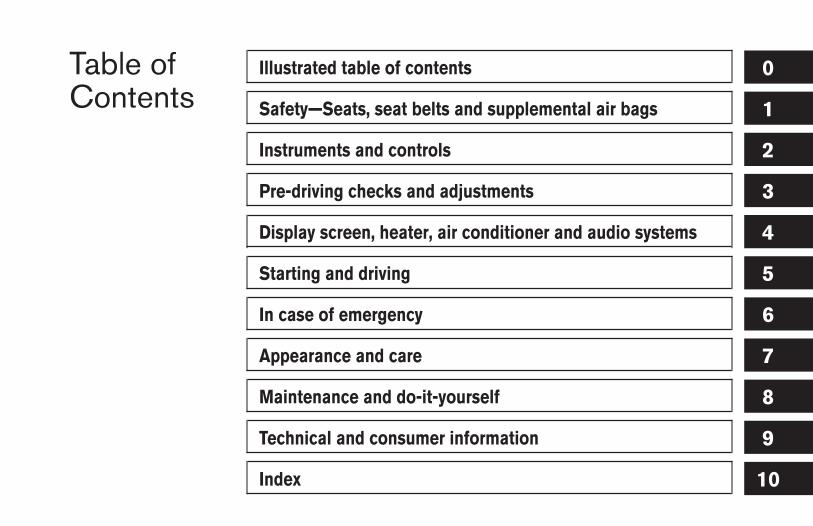
Table ofContents
Illustrated table of contents
Safety—Seats, seat belts and supplemental air bags
Instruments and controls
Pre-driving checks and adjustments
Display screen, heater, air conditioner and audio systems
Starting and driving
In case of emergency
Appearance and care
Maintenance and do-it-yourself
Technical and consumer information
Index
0
1
2
3
4
5
6
7
8
9
10

Z REVIEW COPY:—2004 Maxima (max)Owners Manual (owners)—USA English (nna)10/07/03—tbrooks X
0 Illustrated table of contents
Airbags, seat belts and child restraints . . . . . . . . . . . . . . . 0-2Exterior front . . . . . . . . . . . . . . . . . . . . . . . . . . . . . . . . . . . . . . 0-3Exterior rear. . . . . . . . . . . . . . . . . . . . . . . . . . . . . . . . . . . . . . . 0-4Passenger compartment . . . . . . . . . . . . . . . . . . . . . . . . . . . 0-5
Instrument panel. . . . . . . . . . . . . . . . . . . . . . . . . . . . . . . . . . . 0-6Engine compartment locations . . . . . . . . . . . . . . . . . . . . . . 0-8Warning/indicator lights . . . . . . . . . . . . . . . . . . . . . . . . . . . . 0-9
Z REVIEW COPY:—2004 Maxima (max)Owners Manual (owners)—USA English (nna)10/20/03—arosenma X
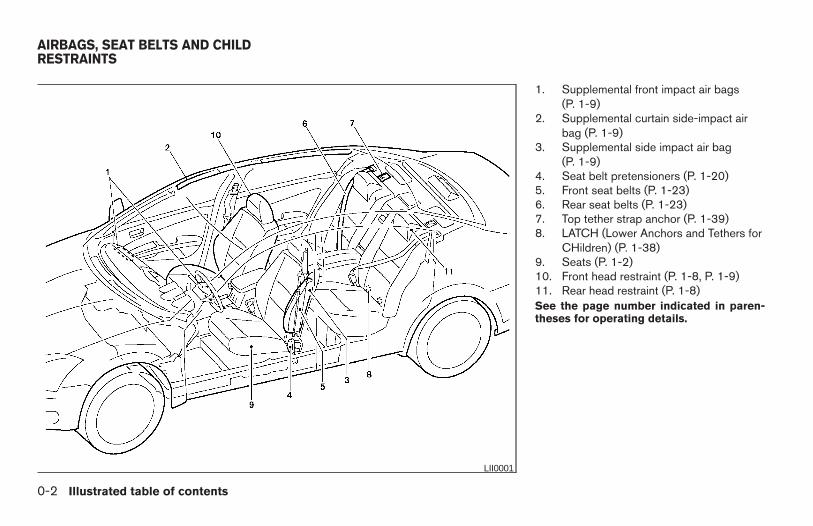
1. Supplemental front impact air bags(P. 1-9)
2. Supplemental curtain side-impact airbag (P. 1-9)
3. Supplemental side impact air bag(P. 1-9)
4. Seat belt pretensioners (P. 1-20)5. Front seat belts (P. 1-23)6. Rear seat belts (P. 1-23)7. Top tether strap anchor (P. 1-39)8. LATCH (Lower Anchors and Tethers for
CHildren) (P. 1-38)9. Seats (P. 1-2)10. Front head restraint (P. 1-8, P. 1-9)11. Rear head restraint (P. 1-8)See the page number indicated in paren-theses for operating details.
LII0001
AIRBAGS, SEAT BELTS AND CHILDRESTRAINTS
0-2 Illustrated table of contents
Z REVIEW COPY:—2004 Maxima (max)Owners Manual (owners)—USA English (nna)10/20/03—arosenma X
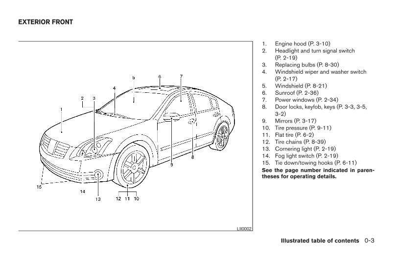
1. Engine hood (P. 3-10)2. Headlight and turn signal switch
(P. 2-19)3. Replacing bulbs (P. 8-30)4. Windshield wiper and washer switch
(P. 2-17)5. Windshield (P. 8-21)6. Sunroof (P. 2-36)7. Power windows (P. 2-34)8. Door locks, keyfob, keys (P. 3-3, 3-5,
3-2)9. Mirrors (P. 3-17)10. Tire pressure (P. 9-11)11. Flat tire (P. 6-2)12. Tire chains (P. 8-39)13. Cornering light (P. 2-19)14. Fog light switch (P. 2-19)15. Tie down/towing hooks (P. 6-11)See the page number indicated in paren-theses for operating details.
LII0002
EXTERIOR FRONT
Illustrated table of contents 0-3
Z REVIEW COPY:—2004 Maxima (max)Owners Manual (owners)—USA English (nna)10/20/03—arosenma X
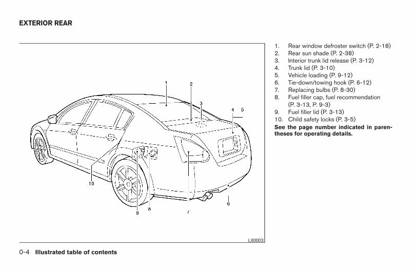
1. Rear window defroster switch (P. 2-18)2. Rear sun shade (P. 2-38)3. Interior trunk lid release (P. 3-12)4. Trunk lid (P. 3-10)5. Vehicle loading (P. 9-12)6. Tie-down/towing hook (P. 6-12)7. Replacing bulbs (P. 8-30)8. Fuel filler cap, fuel recommendation
(P. 3-13, P. 9-3)9. Fuel filler lid (P. 3-13)10. Child safety locks (P. 3-5)See the page number indicated in paren-theses for operating details.
LII0003
EXTERIOR REAR
0-4 Illustrated table of contents
Z REVIEW COPY:—2004 Maxima (max)Owners Manual (owners)—USA English (nna)10/20/03—arosenma X
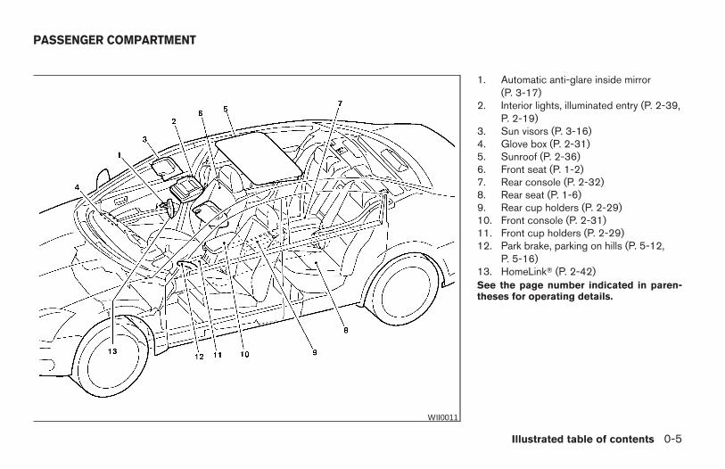
1. Automatic anti-glare inside mirror(P. 3-17)
2. Interior lights, illuminated entry (P. 2-39,P. 2-19)
3. Sun visors (P. 3-16)4. Glove box (P. 2-31)5. Sunroof (P. 2-36)6. Front seat (P. 1-2)7. Rear console (P. 2-32)8. Rear seat (P. 1-6)9. Rear cup holders (P. 2-29)10. Front console (P. 2-31)11. Front cup holders (P. 2-29)12. Park brake, parking on hills (P. 5-12,
P. 5-16)13. HomeLinkT (P. 2-42)See the page number indicated in paren-theses for operating details.
WII0011
PASSENGER COMPARTMENT
Illustrated table of contents 0-5
Z REVIEW COPY:—2004 Maxima (max)Owners Manual (owners)—USA English (nna)10/20/03—arosenma X
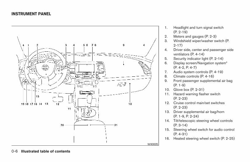
1. Headlight and turn signal switch(P. 2-19)
2. Meters and gauges (P. 2-3)3. Windshield wiper/washer switch (P.
2-17)4. Driver side, center and passenger side
ventilators (P. 4-14)5. Security indicator light (P. 2-14)6. Display screen/Navigation system*
(P. 4-2, P. 4-7)7. Audio system controls (P. 4-19)8. Climate controls (P. 4-16)9. Front passenger supplemental air bag
(P. 1-9)10. Glove box (P. 2-31)11. Hazard warning flasher switch
(P. 2-23)12. Cruise control main/set switches
(P. 2-23)13. Driver supplemental air bag/horn
(P. 1-9, P. 2-24)14. Tilt/telescopic steering wheel controls
(P. 3-14)15. Steering wheel switch for audio control
(P. 4-31)16. Heated steering wheel switch (P. 2-25)
WII0005
INSTRUMENT PANEL
0-6 Illustrated table of contents
Z REVIEW COPY:—2004 Maxima (max)Owners Manual (owners)—USA English (nna)10/20/03—arosenma X
17. Vehicle dynamic control (VDC) offswitch (if so equipped) or Traction con-trol system (TCS) off switch (if soequipped) (P. 2-26, P. 2-26)
18. Outside mirror controls (P. 3-17)19. Instrument brightness control (P. 2-22)20. Heated seat switch (if so equipped)
(P. 2-24)21. Rear sunshade switch (if so equipped)
(P. 2-38)*: Refer to the separate Navigation System Own-er’s Manual (if so equipped).
See the page number indicated in paren-theses for operating details.
Illustrated table of contents 0-7
Z REVIEW COPY:—2004 Maxima (max)Owners Manual (owners)—USA English (nna)10/20/03—arosenma X
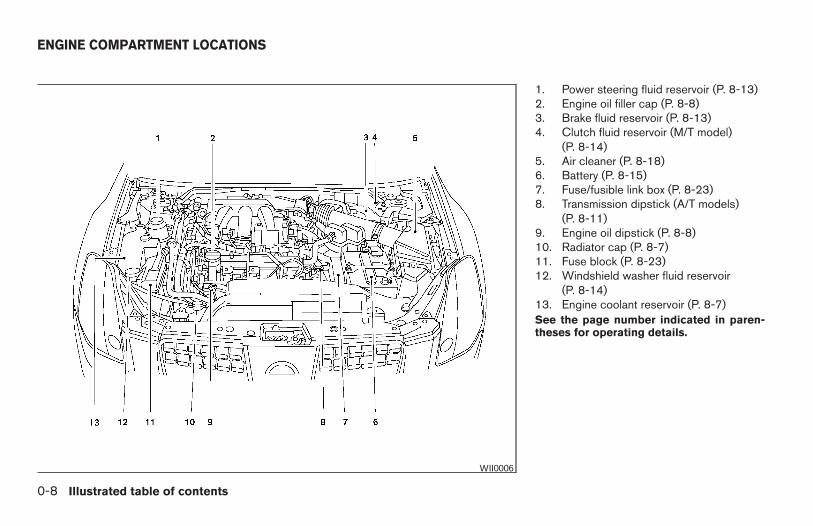
1. Power steering fluid reservoir (P. 8-13)2. Engine oil filler cap (P. 8-8)3. Brake fluid reservoir (P. 8-13)4. Clutch fluid reservoir (M/T model)
(P. 8-14)5. Air cleaner (P. 8-18)6. Battery (P. 8-15)7. Fuse/fusible link box (P. 8-23)8. Transmission dipstick (A/T models)
(P. 8-11)9. Engine oil dipstick (P. 8-8)10. Radiator cap (P. 8-7)11. Fuse block (P. 8-23)12. Windshield washer fluid reservoir
(P. 8-14)13. Engine coolant reservoir (P. 8-7)See the page number indicated in paren-theses for operating details.
WII0006
ENGINE COMPARTMENT LOCATIONS
0-8 Illustrated table of contents
Z REVIEW COPY:—2004 Maxima (max)Owners Manual (owners)—USA English (nna)10/20/03—skoniecz X
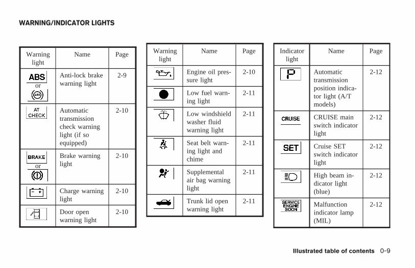
Warninglight
Name Page
or
Anti-lock brakewarning light
2-9
Automatictransmissioncheck warninglight (if soequipped)
2-10
or
Brake warninglight
2-10
Charge warninglight
2-10
Door openwarning light
2-10
Warninglight
Name Page
Engine oil pres-sure light
2-10
Low fuel warn-ing light
2-11
Low windshieldwasher fluidwarning light
2-11
Seat belt warn-ing light andchime
2-11
Supplementalair bag warninglight
2-11
Trunk lid openwarning light
2-11
Indicatorlight
Name Page
Automatictransmissionposition indica-tor light (A/Tmodels)
2-12
CRUISE mainswitch indicatorlight
2-12
Cruise SETswitch indicatorlight
2-12
High beam in-dicator light(blue)
2-12
Malfunctionindicator lamp(MIL)
2-12
WARNING/INDICATOR LIGHTS
Illustrated table of contents 0-9
Z REVIEW COPY:—2004 Maxima (max)Owners Manual (owners)—USA English (nna)10/20/03—skoniecz X
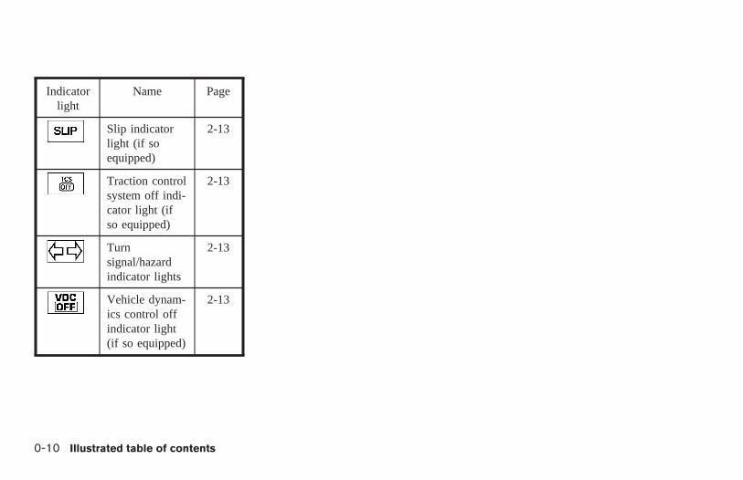
Indicatorlight
Name Page
Slip indicatorlight (if soequipped)
2-13
Traction controlsystem off indi-cator light (ifso equipped)
2-13
Turnsignal/hazardindicator lights
2-13
Vehicle dynam-ics control offindicator light(if so equipped)
2-13
0-10 Illustrated table of contents
Z REVIEW COPY:—2004 Maxima (max)Owners Manual (owners)—USA English (nna)10/20/03—arosenma X
1 Safety—Seats, seat belts andsupplemental air bags
Seats . . . . . . . . . . . . . . . . . . . . . . . . . . . . . . . . . . . . . . . . . . . . 1-2Front manual seat adjustment — passengerside . . . . . . . . . . . . . . . . . . . . . . . . . . . . . . . . . . . . . . . . . . . 1-2Front power seat adjustment (for driver’sseat and if so equipped for passenger’sseat) . . . . . . . . . . . . . . . . . . . . . . . . . . . . . . . . . . . . . . . . . . 1-4Folding rear seat (if so equipped). . . . . . . . . . . . . . . . . 1-6Head restraint adjustment . . . . . . . . . . . . . . . . . . . . . . . 1-8Active head restraint (front seats). . . . . . . . . . . . . . . . . 1-9
Supplemental restraint system . . . . . . . . . . . . . . . . . . . . . . 1-9Precautions on supplemental restraintsystem . . . . . . . . . . . . . . . . . . . . . . . . . . . . . . . . . . . . . . . . 1-9Supplemental air bag warning labels . . . . . . . . . . . . . 1-21Supplemental air bag warning light . . . . . . . . . . . . . . 1-21
Seat belts . . . . . . . . . . . . . . . . . . . . . . . . . . . . . . . . . . . . . . .1-23
Precautions on seat belt usage. . . . . . . . . . . . . . . . . . 1-23Child safety . . . . . . . . . . . . . . . . . . . . . . . . . . . . . . . . . . .1-25Pregnant women . . . . . . . . . . . . . . . . . . . . . . . . . . . . . .1-26Injured persons. . . . . . . . . . . . . . . . . . . . . . . . . . . . . . . .1-26Three-point type seat belt with retractor . . . . . . . . . . 1-27Seat belt extenders . . . . . . . . . . . . . . . . . . . . . . . . . . . .1-30Seat belt maintenance . . . . . . . . . . . . . . . . . . . . . . . . . 1-30
Child restraints . . . . . . . . . . . . . . . . . . . . . . . . . . . . . . . . . . .1-31Precautions on child restraints . . . . . . . . . . . . . . . . . . 1-31Installation on rear seat center (5-passengermodels only) or outboard positions . . . . . . . . . . . . . . 1-33LATCH (Lower Anchors and Tethers forCHildren) system . . . . . . . . . . . . . . . . . . . . . . . . . . . . . .1-38Top tether strap child restraint . . . . . . . . . . . . . . . . . . 1-39Installation on front passenger seat . . . . . . . . . . . . . . 1-40
Z REVIEW COPY:—2004 Maxima (max)Owners Manual (owners)—USA English (nna)10/20/03—arosenma X
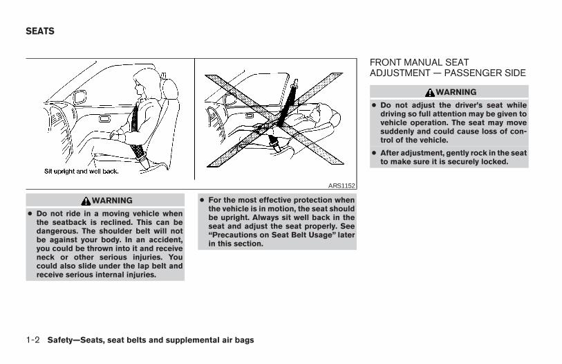
WARNING
● Do not ride in a moving vehicle whenthe seatback is reclined. This can bedangerous. The shoulder belt will notbe against your body. In an accident,you could be thrown into it and receiveneck or other serious injuries. Youcould also slide under the lap belt andreceive serious internal injuries.
● For the most effective protection whenthe vehicle is in motion, the seat shouldbe upright. Always sit well back in theseat and adjust the seat properly. See“Precautions on Seat Belt Usage” laterin this section.
FRONT MANUAL SEATADJUSTMENT — PASSENGER SIDE
WARNING
● Do not adjust the driver’s seat whiledriving so full attention may be given tovehicle operation. The seat may movesuddenly and could cause loss of con-trol of the vehicle.
● After adjustment, gently rock in the seatto make sure it is securely locked.
ARS1152
SEATS
1-2 Safety—Seats, seat belts and supplemental air bags
Z REVIEW COPY:—2004 Maxima (max)Owners Manual (owners)—USA English (nna)10/07/03—tbrooks X
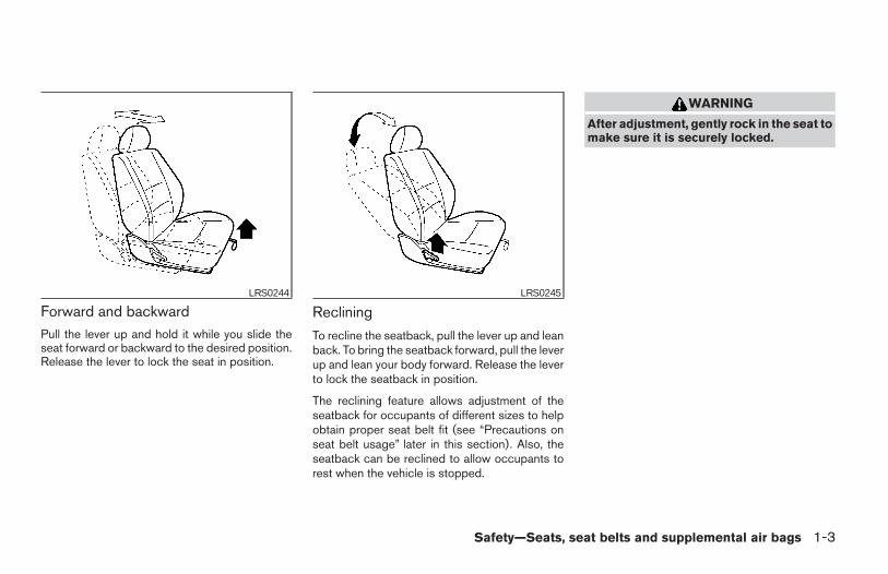
Forward and backwardPull the lever up and hold it while you slide theseat forward or backward to the desired position.Release the lever to lock the seat in position.
Reclining
To recline the seatback, pull the lever up and leanback. To bring the seatback forward, pull the leverup and lean your body forward. Release the leverto lock the seatback in position.
The reclining feature allows adjustment of theseatback for occupants of different sizes to helpobtain proper seat belt fit (see “Precautions onseat belt usage” later in this section). Also, theseatback can be reclined to allow occupants torest when the vehicle is stopped.
WARNING
After adjustment, gently rock in the seat tomake sure it is securely locked.
LRS0244 LRS0245
Safety—Seats, seat belts and supplemental air bags 1-3
Z REVIEW COPY:—2004 Maxima (max)Owners Manual (owners)—USA English (nna)10/07/03—tbrooks X
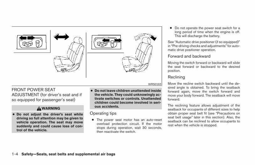
FRONT POWER SEATADJUSTMENT (for driver’s seat and ifso equipped for passenger’s seat)
WARNING
● Do not adjust the driver’s seat whiledriving so full attention may be given tovehicle operation. The seat may movesuddenly and could cause loss of con-trol of the vehicle.
● Do not leave children unattended insidethe vehicle. They could unknowingly ac-tivate switches or controls. Unattendedchildren could become involved in seri-ous accidents.
Operating tips● The power seat motor has an auto-reset
overload protection circuit. If the motorstops during operation, wait 30 seconds,then reactivate the switch.
● Do not operate the power seat switch for along period of time when the engine is off.This will discharge the battery.
See “Automatic drive positioner (if so equipped)”in “Pre-driving checks and adjustments” for auto-matic drive positioner operation.
Forward and backwardMoving the switch forward or backward will slidethe seat forward or backward to the desiredposition.
RecliningMove the recline switch backward until the de-sired angle is obtained. To bring the seatbackforward again, move the switch forward andmove your body forward. The seatback will moveforward.
The reclining feature allows adjustment of theseatback for occupants of different sizes to helpobtain proper seat belt fit (see “Precautions onseat belt usage” later in this section). Also, theseatback can be reclined to allow occupants torest when the vehicle is stopped.
WRS0163
1-4 Safety—Seats, seat belts and supplemental air bags
Z REVIEW COPY:—2004 Maxima (max)Owners Manual (owners)—USA English (nna)10/20/03—skoniecz X
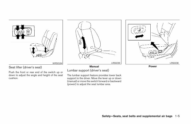
Seat lifter (driver’s seat)Push the front or rear end of the switch up ordown to adjust the angle and height of the seatcushion.
Lumbar support (driver’s seat)The lumbar support feature provides lower backsupport to the driver. Move the lever up or down(manual) or move the switch forward or backward(power) to adjust the seat lumbar area.
WRS0164
ManualLRS0239
PowerLRS0238
Safety—Seats, seat belts and supplemental air bags 1-5
Z REVIEW COPY:—2004 Maxima (max)Owners Manual (owners)—USA English (nna)10/07/03—tbrooks X
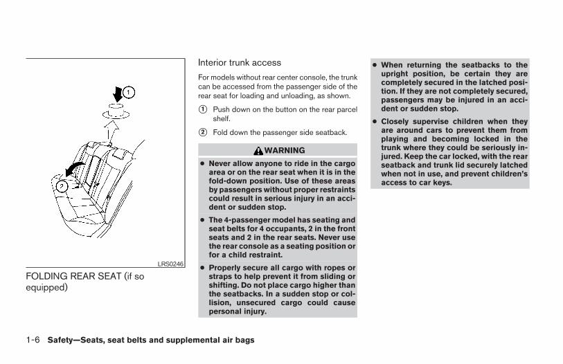
FOLDING REAR SEAT (if soequipped)
Interior trunk access
For models without rear center console, the trunkcan be accessed from the passenger side of therear seat for loading and unloading, as shown.
s1 Push down on the button on the rear parcelshelf.
s2 Fold down the passenger side seatback.
WARNING
● Never allow anyone to ride in the cargoarea or on the rear seat when it is in thefold-down position. Use of these areasby passengers without proper restraintscould result in serious injury in an acci-dent or sudden stop.
● The 4-passenger model has seating andseat belts for 4 occupants, 2 in the frontseats and 2 in the rear seats. Never usethe rear console as a seating position orfor a child restraint.
● Properly secure all cargo with ropes orstraps to help prevent it from sliding orshifting. Do not place cargo higher thanthe seatbacks. In a sudden stop or col-lision, unsecured cargo could causepersonal injury.
● When returning the seatbacks to theupright position, be certain they arecompletely secured in the latched posi-tion. If they are not completely secured,passengers may be injured in an acci-dent or sudden stop.
● Closely supervise children when theyare around cars to prevent them fromplaying and becoming locked in thetrunk where they could be seriously in-jured. Keep the car locked, with the rearseatback and trunk lid securely latchedwhen not in use, and prevent children’saccess to car keys.
LRS0246
1-6 Safety—Seats, seat belts and supplemental air bags
Z REVIEW COPY:—2004 Maxima (max)Owners Manual (owners)—USA English (nna)10/07/03—tbrooks X
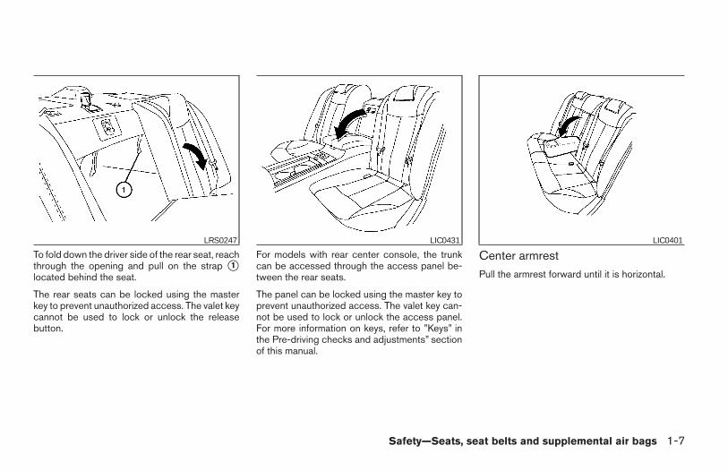
To fold down the driver side of the rear seat, reachthrough the opening and pull on the strap s1located behind the seat.
The rear seats can be locked using the masterkey to prevent unauthorized access. The valet keycannot be used to lock or unlock the releasebutton.
For models with rear center console, the trunkcan be accessed through the access panel be-tween the rear seats.
The panel can be locked using the master key toprevent unauthorized access. The valet key can-not be used to lock or unlock the access panel.For more information on keys, refer to ”Keys” inthe Pre-driving checks and adjustments” sectionof this manual.
Center armrestPull the armrest forward until it is horizontal.
LRS0247 LIC0431 LIC0401
Safety—Seats, seat belts and supplemental air bags 1-7
Z REVIEW COPY:—2004 Maxima (max)Owners Manual (owners)—USA English (nna)10/07/03—tbrooks X
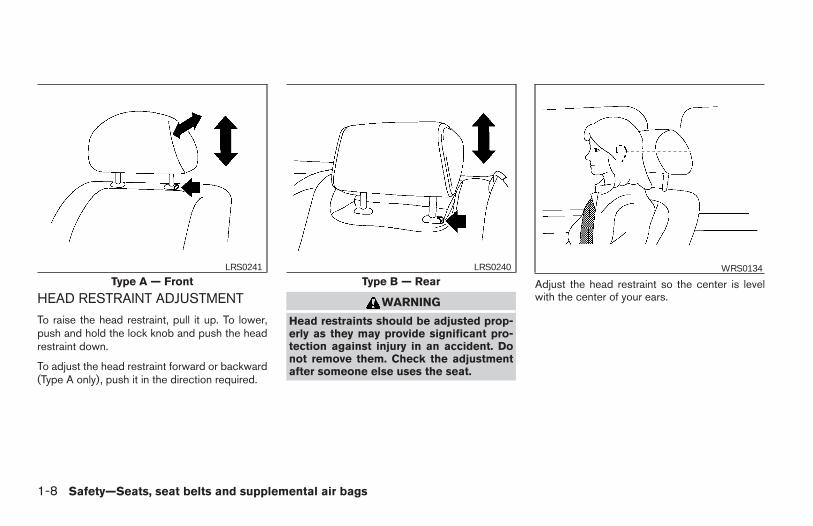
HEAD RESTRAINT ADJUSTMENT
To raise the head restraint, pull it up. To lower,push and hold the lock knob and push the headrestraint down.
To adjust the head restraint forward or backward(Type A only), push it in the direction required.
WARNING
Head restraints should be adjusted prop-erly as they may provide significant pro-tection against injury in an accident. Donot remove them. Check the adjustmentafter someone else uses the seat.
Adjust the head restraint so the center is levelwith the center of your ears.
Type A — FrontLRS0241
Type B — RearLRS0240 WRS0134
1-8 Safety—Seats, seat belts and supplemental air bags
Z REVIEW COPY:—2004 Maxima (max)Owners Manual (owners)—USA English (nna)10/07/03—tbrooks X
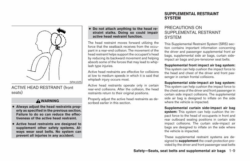
ACTIVE HEAD RESTRAINT (frontseats)
WARNING
● Always adjust the head restraints prop-erly as specified in the previous section.Failure to do so can reduce the effec-tiveness of the active head restraint.
● Active head restraints are designed tosupplement other safety systems. Al-ways wear seat belts. No system canprevent all injuries in any accident.
● Do not attach anything to the head re-straint stalks. Doing so could impairactive head restraint function.
The head restraint moves forward utilizing theforce that the seatback receives from the occu-pant in a rear-end collision. The movement of thehead restraint helps support the occupant’s headby reducing its backward movement and helpingabsorb some of the forces that may lead to whip-lash type injuries.
Active head restraints are effective for collisionsat low to medium speeds in which it is said thatwhiplash injury occurs most.
Active head restraints operate only in certainrear-end collisions. After the collision, the headrestraints return to their original positions.
Properly adjust the active head restraints as de-scribed earlier in this section.
PRECAUTIONS ONSUPPLEMENTAL RESTRAINTSYSTEM
This Supplemental Restraint System (SRS) sec-tion contains important information concerningthe driver and passenger supplemental front airbags, supplemental side air bags, curtain side-impact air bags and pre-tensioner seat belts.
Supplemental front impact air bag system:This system can help cushion the impact force tothe head and chest of the driver and front pas-senger in certain frontal collisions.
Supplemental side-impact air bag system:This system can help cushion the impact force tothe chest area of the driver and front passenger incertain side impact collisions. The supplementalside air bag is designed to inflate on the sidewhere the vehicle is impacted.
Supplemental curtain side-impact air bagsystem: This system can help cushion the im-pact force to the head of occupants in front andrear outboard seating positions in certain sideimpact collisions. The curtain side-impact airbags are designed to inflate on the side wherethe vehicle is impacted.
These supplemental restraint systems are de-signed to supplement the crash protection pro-vided by the driver and front passenger seat belts
SPA1025
SUPPLEMENTAL RESTRAINTSYSTEM
Safety—Seats, seat belts and supplemental air bags 1-9
Z REVIEW COPY:—2004 Maxima (max)Owners Manual (owners)—USA English (nna)10/07/03—tbrooks X
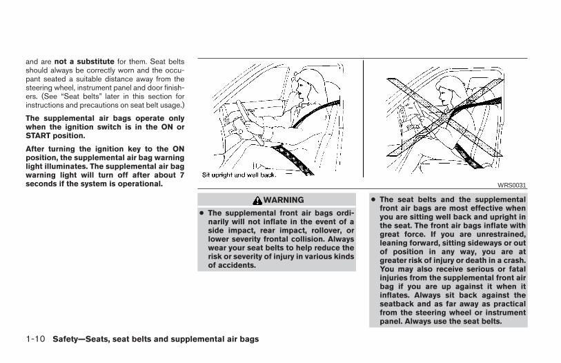
and are not a substitute for them. Seat beltsshould always be correctly worn and the occu-pant seated a suitable distance away from thesteering wheel, instrument panel and door finish-ers. (See “Seat belts” later in this section forinstructions and precautions on seat belt usage.)
The supplemental air bags operate onlywhen the ignition switch is in the ON orSTART position.
After turning the ignition key to the ONposition, the supplemental air bag warninglight illuminates. The supplemental air bagwarning light will turn off after about 7seconds if the system is operational.
WARNING
● The supplemental front air bags ordi-narily will not inflate in the event of aside impact, rear impact, rollover, orlower severity frontal collision. Alwayswear your seat belts to help reduce therisk or severity of injury in various kindsof accidents.
● The seat belts and the supplementalfront air bags are most effective whenyou are sitting well back and upright inthe seat. The front air bags inflate withgreat force. If you are unrestrained,leaning forward, sitting sideways or outof position in any way, you are atgreater risk of injury or death in a crash.You may also receive serious or fatalinjuries from the supplemental front airbag if you are up against it when itinflates. Always sit back against theseatback and as far away as practicalfrom the steering wheel or instrumentpanel. Always use the seat belts.
WRS0031
1-10 Safety—Seats, seat belts and supplemental air bags
Z REVIEW COPY:—2004 Maxima (max)Owners Manual (owners)—USA English (nna)10/07/03—tbrooks X
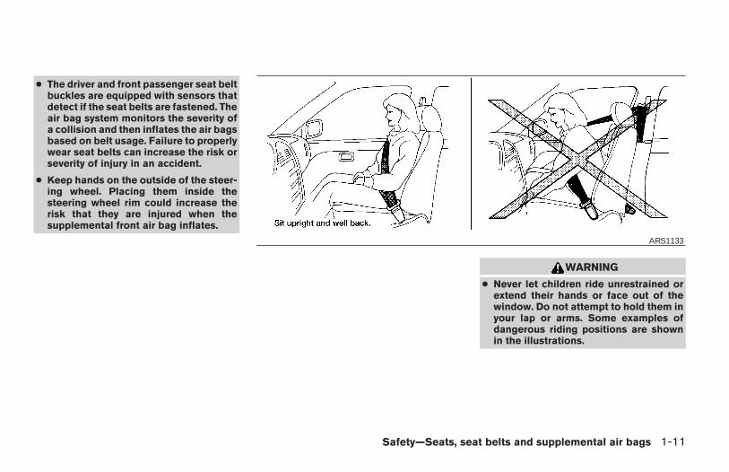
● The driver and front passenger seat beltbuckles are equipped with sensors thatdetect if the seat belts are fastened. Theair bag system monitors the severity ofa collision and then inflates the air bagsbased on belt usage. Failure to properlywear seat belts can increase the risk orseverity of injury in an accident.
● Keep hands on the outside of the steer-ing wheel. Placing them inside thesteering wheel rim could increase therisk that they are injured when thesupplemental front air bag inflates.
WARNING
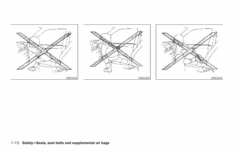
● Never let children ride unrestrained orextend their hands or face out of thewindow. Do not attempt to hold them inyour lap or arms. Some examples ofdangerous riding positions are shownin the illustrations.
ARS1133
Safety—Seats, seat belts and supplemental air bags 1-11
Z REVIEW COPY:—2004 Maxima (max)Owners Manual (owners)—USA English (nna)10/07/03—tbrooks X
ARS1041 ARS1042 ARS1043
1-12 Safety—Seats, seat belts and supplemental air bags
Z REVIEW COPY:—2004 Maxima (max)Owners Manual (owners)—USA English (nna)10/07/03—tbrooks X
WARNING
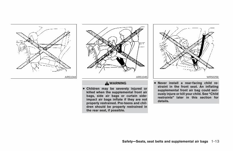
● Children may be severely injured orkilled when the supplemental front airbags, side air bags or curtain side-impact air bags inflate if they are notproperly restrained. Pre-teens and chil-dren should be properly restrained inthe rear seat, if possible.
● Never install a rear-facing child re-straint in the front seat. An inflatingsupplemental front air bag could seri-ously injure or kill your child. See “Childrestraints” later in this section fordetails.
ARS1044 ARS1045 WRS0256
Safety—Seats, seat belts and supplemental air bags 1-13
Z REVIEW COPY:—2004 Maxima (max)Owners Manual (owners)—USA English (nna)10/07/03—tbrooks X
WARNING
Supplemental side air bag and curtainside-impact air bag:
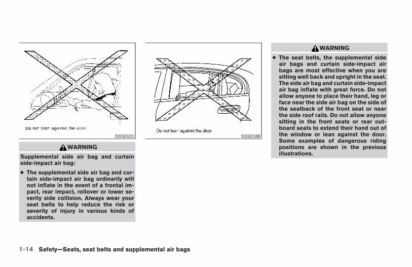
● The supplemental side air bag and cur-tain side-impact air bag ordinarily willnot inflate in the event of a frontal im-pact, rear impact, rollover or lower se-verity side collision. Always wear yourseat belts to help reduce the risk orseverity of injury in various kinds ofaccidents.
WARNING
● The seat belts, the supplemental sideair bags and curtain side-impact airbags are most effective when you aresitting well back and upright in the seat.The side air bag and curtain side-impactair bag inflate with great force. Do notallow anyone to place their hand, leg orface near the side air bag on the side ofthe seatback of the front seat or nearthe side roof rails. Do not allow anyonesitting in the front seats or rear out-board seats to extend their hand out ofthe window or lean against the door.Some examples of dangerous ridingpositions are shown in the previousillustrations.
SSS0101 SSS0188
1-14 Safety—Seats, seat belts and supplemental air bags
Z REVIEW COPY:—2004 Maxima (max)Owners Manual (owners)—USA English (nna)10/07/03—tbrooks X
WARNING
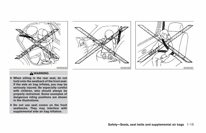
● When sitting in the rear seat, do nothold onto the seatback of the front seat.If the side air bag inflates, you may beseriously injured. Be especially carefulwith children, who should always beproperly restrained. Some examples ofdangerous riding positions are shownin the illustrations.
● Do not use seat covers on the frontseatbacks. They may interfere withsupplemental side air bag inflation.
WRS0032 SSS0159 SSS0162
Safety—Seats, seat belts and supplemental air bags 1-15
Z REVIEW COPY:—2004 Maxima (max)Owners Manual (owners)—USA English (nna)10/07/03—tbrooks X
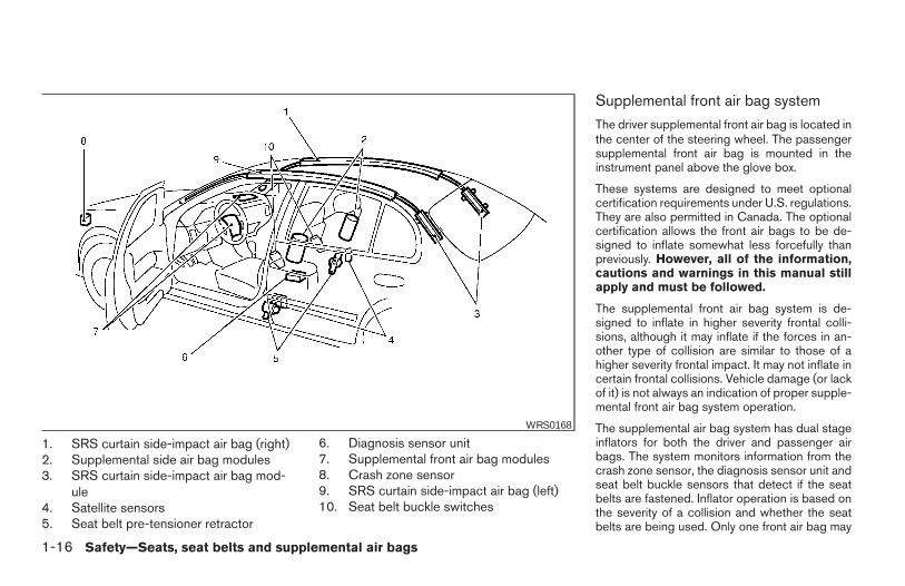
1. SRS curtain side-impact air bag (right)2. Supplemental side air bag modules3. SRS curtain side-impact air bag mod-
ule4. Satellite sensors5. Seat belt pre-tensioner retractor
6. Diagnosis sensor unit7. Supplemental front air bag modules8. Crash zone sensor9. SRS curtain side-impact air bag (left)10. Seat belt buckle switches
Supplemental front air bag system
The driver supplemental front air bag is located inthe center of the steering wheel. The passengersupplemental front air bag is mounted in theinstrument panel above the glove box.
These systems are designed to meet optionalcertification requirements under U.S. regulations.They are also permitted in Canada. The optionalcertification allows the front air bags to be de-signed to inflate somewhat less forcefully thanpreviously. However, all of the information,cautions and warnings in this manual stillapply and must be followed.
The supplemental front air bag system is de-signed to inflate in higher severity frontal colli-sions, although it may inflate if the forces in an-other type of collision are similar to those of ahigher severity frontal impact. It may not inflate incertain frontal collisions. Vehicle damage (or lackof it) is not always an indication of proper supple-mental front air bag system operation.
The supplemental air bag system has dual stageinflators for both the driver and passenger airbags. The system monitors information from thecrash zone sensor, the diagnosis sensor unit andseat belt buckle sensors that detect if the seatbelts are fastened. Inflator operation is based onthe severity of a collision and whether the seatbelts are being used. Only one front air bag may
WRS0168
1-16 Safety—Seats, seat belts and supplemental air bags
Z REVIEW COPY:—2004 Maxima (max)Owners Manual (owners)—USA English (nna)10/07/03—tbrooks X
inflate in a crash, depending on the crash severityand whether the front occupants are belted orunbelted. This does not indicate improper perfor-mance of the system. If you have any questionsabout the performance of your air bag system,please contact your NISSAN dealer.
When the supplemental front air bag inflates, afairly loud noise may be heard, followed by therelease of smoke. This smoke is not harmful anddoes not indicate a fire. Care should be taken tonot inhale it, as it may cause irritation and chok-ing. Those with a history of a breathing conditionshould get fresh air promptly.
Supplemental front air bags, along with the use ofseat belts, help to cushion the impact force onthe face and chest of the front occupants. Theycan help save lives and reduce serious injuries.However, an inflating front air bag may causefacial abrasions or other injuries. Front air bagsdo not provide restraint to the lower body.
Seat belts should be correctly worn and thedriver and passenger seated upright as far aspractical away from the steering wheel or instru-ment panel. The supplemental front air bags in-flate quickly in order to help protect the frontoccupants. Because of this, the force of the frontair bag inflating can increase the risk of injury ifthe occupant is too close to, or is against, thefront air bag module during inflation.
The front air bags deflate quickly after a collision.
The supplemental front air bags operateonly when the ignition switch is in the ONor START position.
After turning the ignition key to the ONposition, the supplemental air bag warninglight illuminates. The supplemental air bagwarning light will turn off after about 7seconds if the system is operational.
WARNING
● Do not place any objects on the steer-ing wheel pad or on the instrumentpanel. Also, do not place any objectsbetween any occupant and the steeringwheel or instrument panel. Such ob-jects may become dangerous projec-tiles and cause injury if the supplemen-tal front air bag inflates.
● Immediately after inflation, severalfront air bag system components will behot. Do not touch them; you may se-verely burn yourself.
● No unauthorized changes should bemade to any components or wiring ofthe supplemental air bag system. This isto prevent accidental inflation of thesupplemental air bag or damage to thesupplemental air bag system.
● Do not make unauthorized changes toyour vehicle’s electrical system, sus-pension system or front end structure.This could affect proper operation ofthe supplemental front air bag system.
● Tampering with the supplemental frontair bag system may result in seriouspersonal injury. Tampering includeschanges to the steering wheel and theinstrument panel assembly by placingmaterial over the steering wheel padand above the instrument panel or byinstalling additional trim materialaround the air bag system.
Safety—Seats, seat belts and supplemental air bags 1-17
Z REVIEW COPY:—2004 Maxima (max)Owners Manual (owners)—USA English (nna)10/07/03—tbrooks X
● Work on and around the supplementalfront air bag system should be done bya NISSAN dealer. Installation of electri-cal equipment should also be done by aNISSAN dealer. The Supplemental Re-straint System (SRS) wiring should notbe modified or disconnected. Unautho-rized electrical test equipment andprobing devices should not be used onthe air bag system.
● A cracked windshield should be re-placed immediately by a qualified re-pair facility. A cracked windshield couldaffect inflation of the supplemental airbag system.
● The SRS wiring harness connectors areyellow and orange for easyidentification.
When selling your vehicle, we request that youinform the buyer about the supplemental front airbag system and guide the buyer to the appropri-ate sections in this Owner’s Manual.
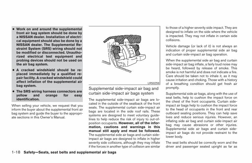
Supplemental side-impact air bag andcurtain side-impact air bags systemThe supplemental side-impact air bags are lo-cated in the outside of the seatback of the frontseats. The supplemental curtain side-impact airbags are located in the side roof rails. Thesesystems are designed to meet voluntary guide-lines to help reduce the risk of injury to out-of-position occupants. However, all of the infor-mation, cautions and warnings in thismanual still apply and must be followed.The supplemental side air bags and curtain side-impact air bags are designed to inflate in higherseverity side collisions, although they may inflateif the forces in another type of collision are similar
to those of a higher severity side impact. They aredesigned to inflate on the side where the vehicleis impacted. They may not inflate in certain sidecollisions.
Vehicle damage (or lack of it) is not always anindication of proper supplemental side air bagand curtain side-impact air bag operation.
When the supplemental side air bag and curtainside-impact air bag inflate, a fairly loud noise maybe heard, followed by release of smoke. Thissmoke is not harmful and does not indicate a fire.Care should be taken not to inhale it, as it maycause irritation and choking. Those with a historyof a breathing condition should get fresh airpromptly.
Supplemental side air bags, along with the use ofseat belts, help to cushion the impact force onthe chest of the front occupants. Curtain side-impact air bags help to cushion the impact forceto the head of occupants in the front and rearoutboard seating positions. They can help savelives and reduce serious injuries. However, aninflating side air bag and curtain side-impact airbag may cause abrasions or other injuries.Supplemental side air bags and curtain side-impact air bags do not provide restraint to thelower body.
The seat belts should be correctly worn and thedriver and passenger seated upright as far as
LRS0259
1-18 Safety—Seats, seat belts and supplemental air bags
Z REVIEW COPY:—2004 Maxima (max)Owners Manual (owners)—USA English (nna)10/07/03—tbrooks X
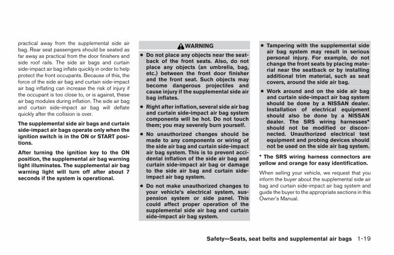
practical away from the supplemental side airbag. Rear seat passengers should be seated asfar away as practical from the door finishers andside roof rails. The side air bags and curtainside-impact air bag inflate quickly in order to helpprotect the front occupants. Because of this, theforce of the side air bag and curtain side-impactair bag inflating can increase the risk of injury ifthe occupant is too close to, or is against, theseair bag modules during inflation. The side air bagand curtain side-impact air bag will deflatequickly after the collision is over.
The supplemental side air bags and curtainside-impact air bags operate only when theignition switch is in the ON or START posi-tions.
After turning the ignition key to the ONposition, the supplemental air bag warninglight illuminates. The supplemental air bagwarning light will turn off after about 7seconds if the system is operational.
WARNING
● Do not place any objects near the seat-back of the front seats. Also, do notplace any objects (an umbrella, bag,etc.) between the front door finisherand the front seat. Such objects maybecome dangerous projectiles andcause injury if the supplemental side airbag inflates.
● Right after inflation, several side air bagand curtain side-impact air bag systemcomponents will be hot. Do not touchthem; you may severely burn yourself.
● No unauthorized changes should bemade to any components or wiring ofthe side air bag and curtain side-impactair bag system. This is to prevent acci-dental inflation of the side air bag andcurtain side-impact air bag or damageto the side air bag and curtain side-impact air bag system.
● Do not make unauthorized changes toyour vehicle’s electrical system, sus-pension system or side panel. Thiscould affect proper operation of thesupplemental side air bag and curtainside-impact air bag system.
● Tampering with the supplemental sideair bag system may result in seriouspersonal injury. For example, do notchange the front seats by placing mate-rial near the seatback or by installingadditional trim material, such as seatcovers, around the side air bag.
● Work around and on the side air bagand curtain side-impact air bag systemshould be done by a NISSAN dealer.Installation of electrical equipmentshould also be done by a NISSANdealer. The SRS wiring harnesses*should not be modified or discon-nected. Unauthorized electrical testequipment and probing devices shouldnot be used on the side air bag system.
* The SRS wiring harness connectors areyellow and orange for easy identification.
When selling your vehicle, we request that youinform the buyer about the supplemental side airbag and curtain side-impact air bag system andguide the buyer to the appropriate sections in thisOwner’s Manual.
Safety—Seats, seat belts and supplemental air bags 1-19
Z REVIEW COPY:—2004 Maxima (max)Owners Manual (owners)—USA English (nna)10/07/03—tbrooks X
Pre-tensioner seat belt system (Forfront seats)
WARNING
● The pre-tensioner seat belt cannot bereused after activation. It must be re-placed together with the retractor andbuckle as a unit.
● If the vehicle becomes involved in afrontal collision but the pre-tensioner isnot activated, be sure to have the pre-tensioner system checked and, if nec-essary, replaced by your NISSANdealer.
● No unauthorized changes should bemade to any components or wiring ofthe pre-tensioner seat belt system. Thisis to prevent accidental activation ofthe pre-tensioner seat belt or damageto the pre-tensioner seat belt operation.Tampering with the pre-tensioner seatbelt system may result in serious per-sonal injury.
● Work around and on the pre-tensionersystem should be done by a NISSANdealer. Installation of electrical equip-ment should also be done by a NISSANdealer. Unauthorized electrical testequipment and probing devices shouldnot be used on the pre-tensioner seatbelt system.
● If you need to dispose of the pre-tensioner or scrap the vehicle, contact aNISSAN dealer. Correct pre-tensionerdisposal procedures are set forth in theappropriate NISSAN Service Manual.Incorrect disposal procedures couldcause personal injury.
The front seat pre-tensioner seat belt systemactivates in conjunction with the supplemental airbag systems. Working with the seat belt retrac-tor, it helps tighten the seat belt when the vehiclebecomes involved in certain types of collisions,helping to restrain front seat occupants.
The pre-tensioner is encased with the seat belt’sretractor. These seat belts are used the same asconventional seat belts.
When the pre-tensioner seat belt activates,smoke is released and a loud noise may be heard.This smoke is not harmful and does not indicate afire. Care should be taken not to inhale it, as it may
cause irritation and choking. Those with a historyof a breathing condition should get fresh airpromptly.
If any abnormality occurs in the pre-tensionersystem, the supplemental air bag warninglight will not come on, will flash intermit-tently or will turn on for 7 seconds and remain onafter the ignition key has been turned to the ON orSTART position. In this case, the pre-tensionerseat belt may not function properly. They must bechecked and repaired. Take your vehicle to thenearest NISSAN dealer.
When selling your vehicle, we request that youinform the buyer about the pre-tensioner seat beltsystem and guide the buyer to the appropriatesections in this Owner’s Manual.
1-20 Safety—Seats, seat belts and supplemental air bags
Z REVIEW COPY:—2004 Maxima (max)Owners Manual (owners)—USA English (nna)10/07/03—tbrooks X
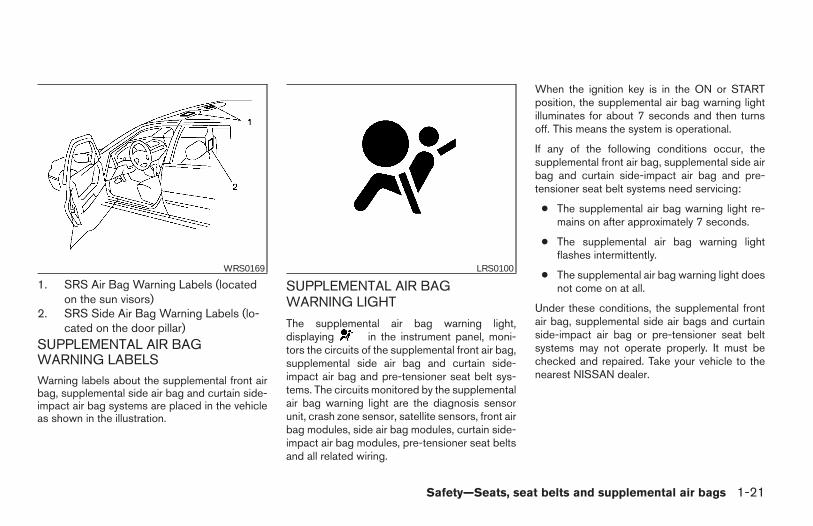
1. SRS Air Bag Warning Labels (locatedon the sun visors)
2. SRS Side Air Bag Warning Labels (lo-cated on the door pillar)
SUPPLEMENTAL AIR BAGWARNING LABELSWarning labels about the supplemental front airbag, supplemental side air bag and curtain side-impact air bag systems are placed in the vehicleas shown in the illustration.
SUPPLEMENTAL AIR BAGWARNING LIGHT
The supplemental air bag warning light,displaying in the instrument panel, moni-tors the circuits of the supplemental front air bag,supplemental side air bag and curtain side-impact air bag and pre-tensioner seat belt sys-tems. The circuits monitored by the supplementalair bag warning light are the diagnosis sensorunit, crash zone sensor, satellite sensors, front airbag modules, side air bag modules, curtain side-impact air bag modules, pre-tensioner seat beltsand all related wiring.
When the ignition key is in the ON or STARTposition, the supplemental air bag warning lightilluminates for about 7 seconds and then turnsoff. This means the system is operational.
If any of the following conditions occur, thesupplemental front air bag, supplemental side airbag and curtain side-impact air bag and pre-tensioner seat belt systems need servicing:
● The supplemental air bag warning light re-mains on after approximately 7 seconds.
● The supplemental air bag warning lightflashes intermittently.
● The supplemental air bag warning light doesnot come on at all.
Under these conditions, the supplemental frontair bag, supplemental side air bags and curtainside-impact air bag or pre-tensioner seat beltsystems may not operate properly. It must bechecked and repaired. Take your vehicle to thenearest NISSAN dealer.
WRS0169 LRS0100
Safety—Seats, seat belts and supplemental air bags 1-21
Z REVIEW COPY:—2004 Maxima (max)Owners Manual (owners)—USA English (nna)10/07/03—tbrooks X
WARNING
If the supplemental air bag warning lightis on, it could mean that the supplementalfront air bag, supplemental side air bag,curtain side-impact air bag systemsand/or pre-tensioner seat belt systemswill not operate in an accident.
Repair and replacement procedure
The supplemental front air bags, supplementalside air bags, curtain side-impact air bags andpre-tensioner seat belts are designed to inflateon a one-time-only basis. As a reminder, unless itis damaged, the supplemental air bag warninglight remains illuminated after inflation has oc-curred. Repair and replacement of these supple-mental air bag systems should be done only by aNISSAN dealer.
When maintenance work is required on the ve-hicle, the supplemental front air bags, supple-mental side air bags, curtain side-impact airbags, pre-tensioner seat belts and related partsshould be pointed out to the person performingthe maintenance. The ignition key should alwaysbe in the LOCK position when working under thehood or inside the vehicle.
WARNING
● Once a supplemental front air bag,supplemental side air bag or curtainside-impact air bag has inflated, the airbag module will not function again andmust be replaced. Additionally, if any ofthe supplemental front air bags inflate,the activated pre-tensioner seat beltsmust also be replaced. The air bag mod-ule and pre-tensioner seat belt systemshould be replaced by a NISSAN dealer.The air bag module and pre-tensionerseat belt system cannot be repaired.
● The supplemental front air bag, side airbag and curtain side-impact air bag sys-tems, and the pre-tensioner seat beltsystem should be inspected by aNISSAN dealer if there is any damage tothe front end or side portion of thevehicle.
● If you need to dispose of the supple-mental air bag, pre-tensioner seat beltsystem or scrap the vehicle, contact aNISSAN dealer. Correct supplementalair bag and pre-tensioner seat belt sys-tem disposal procedures are set forth inthe appropriate NISSAN ServiceManual. Incorrect disposal procedurescould cause personal injury.
1-22 Safety—Seats, seat belts and supplemental air bags
Z REVIEW COPY:—2004 Maxima (max)Owners Manual (owners)—USA English (nna)10/07/03—tbrooks X
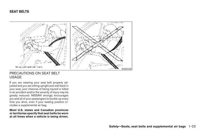
PRECAUTIONS ON SEAT BELTUSAGEIf you are wearing your seat belt properly ad-justed and you are sitting upright and well back inyour seat, your chances of being injured or killedin an accident and/or the severity of injury may begreatly reduced. NISSAN strongly encouragesyou and all of your passengers to buckle up everytime you drive, even if your seating position in-cludes a supplemental air bag.
Most U.S. states and Canadian provincesor territories specify that seat belts be wornat all times when a vehicle is being driven.
SSS0136
SEAT BELTS
Safety—Seats, seat belts and supplemental air bags 1-23
Z REVIEW COPY:—2004 Maxima (max)Owners Manual (owners)—USA English (nna)10/07/03—tbrooks X
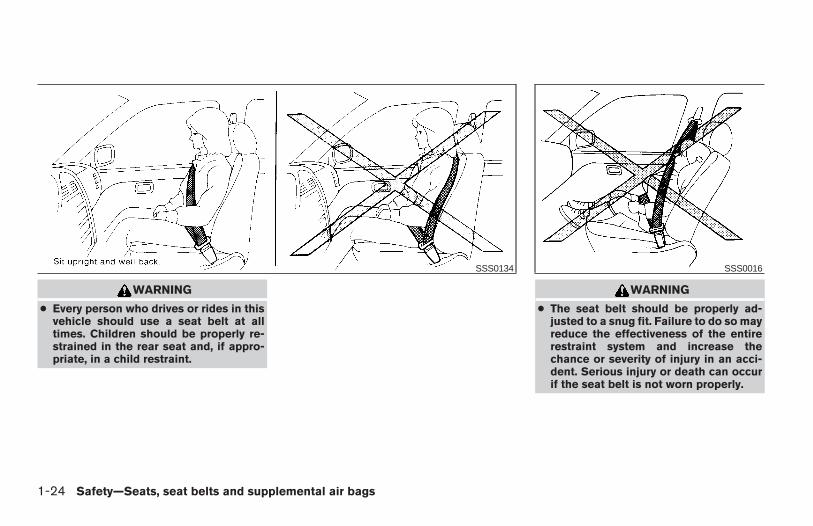
WARNING
● Every person who drives or rides in thisvehicle should use a seat belt at alltimes. Children should be properly re-strained in the rear seat and, if appro-priate, in a child restraint.
WARNING
● The seat belt should be properly ad-justed to a snug fit. Failure to do so mayreduce the effectiveness of the entirerestraint system and increase thechance or severity of injury in an acci-dent. Serious injury or death can occurif the seat belt is not worn properly.
SSS0134 SSS0016
1-24 Safety—Seats, seat belts and supplemental air bags
Z REVIEW COPY:—2004 Maxima (max)Owners Manual (owners)—USA English (nna)10/07/03—tbrooks X
WARNING
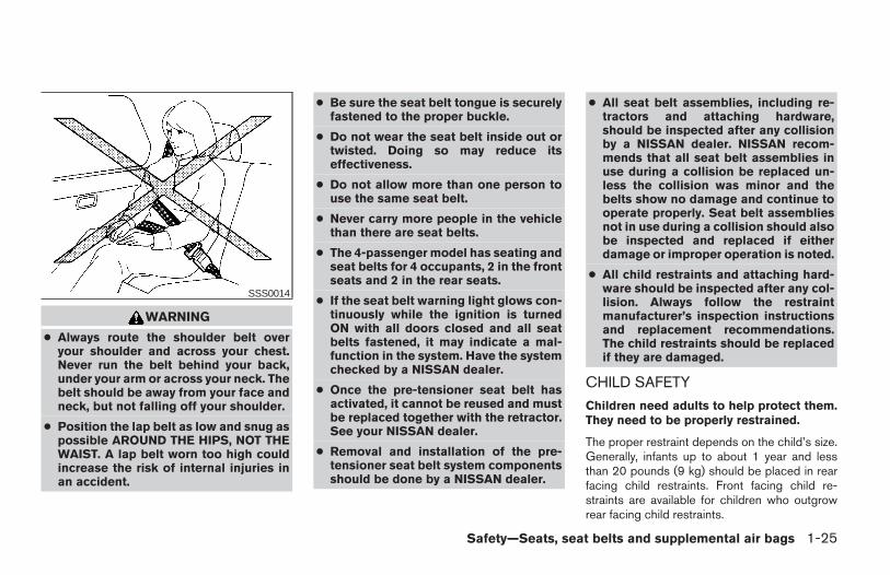
● Always route the shoulder belt overyour shoulder and across your chest.Never run the belt behind your back,under your arm or across your neck. Thebelt should be away from your face andneck, but not falling off your shoulder.
● Position the lap belt as low and snug aspossible AROUND THE HIPS, NOT THEWAIST. A lap belt worn too high couldincrease the risk of internal injuries inan accident.
● Be sure the seat belt tongue is securelyfastened to the proper buckle.
● Do not wear the seat belt inside out ortwisted. Doing so may reduce itseffectiveness.
● Do not allow more than one person touse the same seat belt.
● Never carry more people in the vehiclethan there are seat belts.
● The 4-passenger model has seating andseat belts for 4 occupants, 2 in the frontseats and 2 in the rear seats.
● If the seat belt warning light glows con-tinuously while the ignition is turnedON with all doors closed and all seatbelts fastened, it may indicate a mal-function in the system. Have the systemchecked by a NISSAN dealer.
● Once the pre-tensioner seat belt hasactivated, it cannot be reused and mustbe replaced together with the retractor.See your NISSAN dealer.
● Removal and installation of the pre-tensioner seat belt system componentsshould be done by a NISSAN dealer.
● All seat belt assemblies, including re-tractors and attaching hardware,should be inspected after any collisionby a NISSAN dealer. NISSAN recom-mends that all seat belt assemblies inuse during a collision be replaced un-less the collision was minor and thebelts show no damage and continue tooperate properly. Seat belt assembliesnot in use during a collision should alsobe inspected and replaced if eitherdamage or improper operation is noted.
● All child restraints and attaching hard-ware should be inspected after any col-lision. Always follow the restraintmanufacturer’s inspection instructionsand replacement recommendations.The child restraints should be replacedif they are damaged.
CHILD SAFETY
Children need adults to help protect them.They need to be properly restrained.
The proper restraint depends on the child’s size.Generally, infants up to about 1 year and lessthan 20 pounds (9 kg) should be placed in rearfacing child restraints. Front facing child re-straints are available for children who outgrowrear facing child restraints.
SSS0014
Safety—Seats, seat belts and supplemental air bags 1-25
Z REVIEW COPY:—2004 Maxima (max)Owners Manual (owners)—USA English (nna)10/07/03—tbrooks X
WARNING
Infants and children need special protec-tion. The vehicle’s seat belts may not fitthem properly. The shoulder belt maycome too close to the face or neck. Thelap belt may not fit over their small hipbones. In an accident, an improperly fit-ting seat belt could cause serious or fatalinjury. Always use appropriate childrestraints.
All U.S. states and Canadian provinces or terri-tories require the use of approved child restraintsfor infants and small children. See “Child Re-straints” later in this section.
In addition, there are many types of child re-straints available for larger children which shouldbe used for maximum protection.
NISSAN recommends that all pre-teensand children be restrained in the rear seat.According to accident statistics, childrenare safer when properly restrained in therear seat than in the front seat. This isespecially important because your vehiclehas a supplemental restraint system (Airbag system) for the front passenger. See“Supplemental restraint system” earlier inthis section.
Infants and small children
NISSAN recommends that infants and small chil-dren be placed in child restraints that comply withFederal Motor Vehicle Safety Standards or Ca-nadian Motor Vehicle Safety Standards. Youshould choose a child restraint that fits your ve-hicle and always follow the manufacturer’s in-structions for installation and use.
Larger children
Children who are too large for child restraintsshould be seated and restrained by the seat beltswhich are provided.
If the child’s seating position has a shoulder beltthat fits close to the face or neck, the use of abooster seat (commercially available) may helpovercome this. The booster seat should raise thechild so that the shoulder belt is properly posi-tioned across the top, middle portion of theshoulder and the lap belt is low on the hips. Thebooster seat should fit the vehicle seat and havea label certifying that it complies with FederalMotor Vehicle Safety Standards or Canadian Mo-tor Vehicle Safety Standards. Once the child hasgrown so the shoulder belt is no longer on or nearthe face and neck, use the shoulder belt withoutthe booster seat.
WARNING
Never let a child stand or kneel on anyseat and do not allow a child in the cargoareas while the vehicle is moving. Thechild could be seriously injured or killed inan accident or sudden stop.
PREGNANT WOMEN
NISSAN recommends that pregnant women useseat belts. The seat belt should be worn snug,and always position the lap belt as low as pos-sible around the hips, not the waist. Place theshoulder belt over your shoulder and across yourchest. Never run the lap/shoulder belt over yourabdominal area. Contact your doctor for specificrecommendations.
INJURED PERSONS
NISSAN recommends that injured persons useseat belts. Check with your doctor for specificrecommendations.
1-26 Safety—Seats, seat belts and supplemental air bags
Z REVIEW COPY:—2004 Maxima (max)Owners Manual (owners)—USA English (nna)10/07/03—tbrooks X
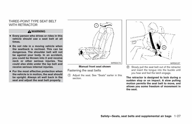
THREE-POINT TYPE SEAT BELTWITH RETRACTOR
WARNING
● Every person who drives or rides in thisvehicle should use a seat belt at alltimes.
● Do not ride in a moving vehicle whenthe seatback is reclined. This can bedangerous. The shoulder belt will notbe against your body. In an accident,you could be thrown into it and receiveneck or other serious injuries. Youcould also slide under the lap belt andreceive serious internal injuries.
● For the most effective protection whenthe vehicle is in motion, the seat shouldbe upright. Always sit well back in theseat and adjust the seat belt properly.
Fastening the seat belts
s1 Adjust the seat. See “Seats” earlier in thissection.
s2 Slowly pull the seat belt out of the retractorand insert the tongue into the buckle untilyou hear and feel the latch engage.
The retractor is designed to lock during asudden stop or on impact. A slow pullingmotion permits the seat belt to move, andallows you some freedom of movement inthe seat.
Manual front seat shownWRS0174 WRS0137
Safety—Seats, seat belts and supplemental air bags 1-27
Z REVIEW COPY:—2004 Maxima (max)Owners Manual (owners)—USA English (nna)10/07/03—tbrooks X
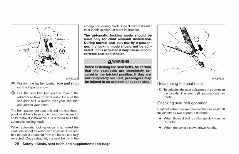
s3 Position the lap belt portion low and snugon the hips as shown.
s4 Pull the shoulder belt portion toward theretractor to take up extra slack. Be sure theshoulder belt is routed over your shoulderand across your chest.
The front passenger seat belt and the rear three-point seat belts have a cinching mechanism forchild restraint installation. It is referred to as theautomatic locking mode.
When automatic locking mode is activated theseat belt cannot be withdrawn again until the seatbelt tongue is detached from the buckle and fullyretracted. Once retracted, the seat belt is in the
emergency locking mode. See “Child restraints”later in this section for more information.
The automatic locking mode should beused only for child restraint installation.During normal seat belt use by a passen-ger, the locking mode should not be acti-vated. If it is activated it may cause uncom-fortable seat belt tension.
WARNING
When fastening the seat belts, be certainthat the seatbacks are completely se-cured in the latched position. If they arenot completely secured, passengers maybe injured in an accident or sudden stop. Unfastening the seat belts
s1 To unfasten the seat belt, press the button onthe buckle. The seat belt automatically re-tracts.
Checking seat belt operationSeat belt retractors are designed to lock seat beltmovement by two separate methods:
● When the seat belt is pulled quickly from theretractor.
● When the vehicle slows down rapidly.
WRS0138 WRS0139
1-28 Safety—Seats, seat belts and supplemental air bags
Z REVIEW COPY:—2004 Maxima (max)Owners Manual (owners)—USA English (nna)10/07/03—tbrooks X
To increase your confidence in the seat belts,check the operation as follows.
● Grasp the shoulder belt and pull forwardquickly. The retractor should lock and re-strict further belt movement.
If the retractor does not lock during this check orif you have any questions about seat belt opera-tion, see a NISSAN dealer.
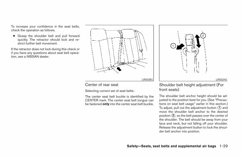
Center of rear seatSelecting correct set of seat belts:
The center seat belt buckle is identified by theCENTER mark. The center seat belt tongue canbe fastened only into the center seat belt buckle.
Shoulder belt height adjustment (Forfront seats)
The shoulder belt anchor height should be ad-justed to the position best for you. (See “Precau-tions on seat belt usage” earlier in this section.)To adjust, pull out the adjustment button s1 andmove the shoulder belt anchor to the desiredposition s2 , so the belt passes over the center ofthe shoulder. The belt should be away from yourface and neck, but not falling off your shoulder.Release the adjustment button to lock the shoul-der belt anchor into position.
LRS0391 LRS0242
Safety—Seats, seat belts and supplemental air bags 1-29
Z REVIEW COPY:—2004 Maxima (max)Owners Manual (owners)—USA English (nna)10/07/03—tbrooks X
WARNING
● After adjustment, release the adjust-ment button and try to move the shoul-der belt anchor up and down to makesure it is securely fixed in position.
● The shoulder belt anchor height shouldbe adjusted to the position best for you.Failure to do so may reduce the effec-tiveness of the entire restraint systemand increase the chance or severity ofinjury in an accident.
SEAT BELT EXTENDERS
If, because of body size or driving position, it isnot possible to properly fit the lap-shoulder beltand fasten it, an extender is available which iscompatible with the installed seat belts. The ex-tender adds approximately 8 inches (200 mm) oflength and may be used for either the driver orfront passenger seating position. See a NISSANdealer for assistance if an extender is required.
WARNING
● Only NISSAN seat belt extenders, madeby the same company which made theoriginal equipment seat belts, shouldbe used with NISSAN seat belts.
● Adults and children who can use thestandard seat belt should not use anextender. Such unnecessary use couldresult in serious personal injury in theevent of an accident.
● Never use seat belt extenders to installchild restraints. If the child restraint isnot secured properly, the child could beseriously injured in a collision or a sud-den stop.
SEAT BELT MAINTENANCE● To clean the seat belt webbing, apply a
mild soap solution or any solution recom-mended for cleaning upholstery or carpet.Then wipe with a cloth and allow the seatbelts to dry in the shade. Do not allow theseat belts to retract until they are completelydry.
● If dirt builds up in the shoulder beltguide of the seat belt anchors, the seatbelts may retract slowly. Wipe the shoulderbelt guide with a clean, dry cloth.
● Periodically check to see that the seatbelt and the metal components, such asbuckles, tongues, retractors, flexible wiresand anchors, work properly. If loose parts,deterioration, cuts or other damage on thewebbing is found, the entire seat belt as-sembly should be replaced.
1-30 Safety—Seats, seat belts and supplemental air bags
Z REVIEW COPY:—2004 Maxima (max)Owners Manual (owners)—USA English (nna)10/07/03—tbrooks X
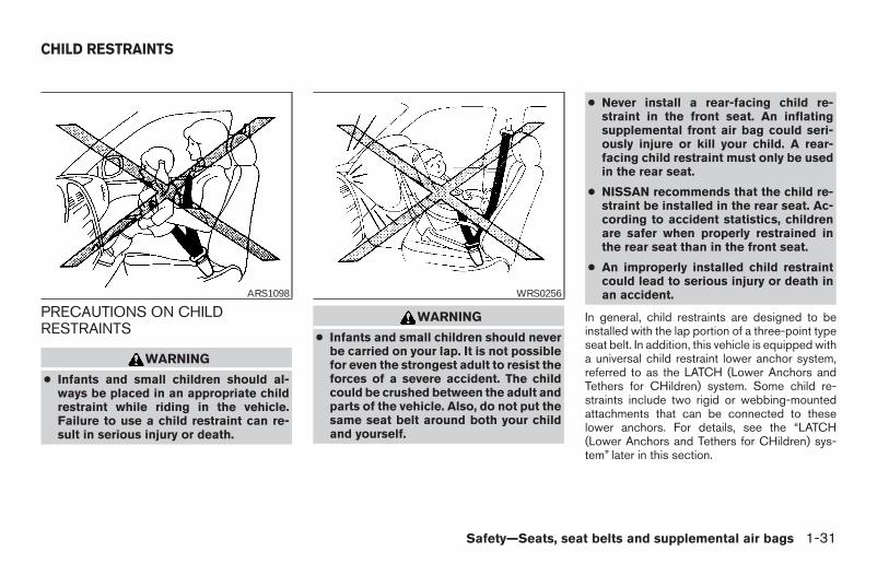
PRECAUTIONS ON CHILDRESTRAINTS
WARNING
● Infants and small children should al-ways be placed in an appropriate childrestraint while riding in the vehicle.Failure to use a child restraint can re-sult in serious injury or death.
WARNING
● Infants and small children should neverbe carried on your lap. It is not possiblefor even the strongest adult to resist theforces of a severe accident. The childcould be crushed between the adult andparts of the vehicle. Also, do not put thesame seat belt around both your childand yourself.
● Never install a rear-facing child re-straint in the front seat. An inflatingsupplemental front air bag could seri-ously injure or kill your child. A rear-facing child restraint must only be usedin the rear seat.
● NISSAN recommends that the child re-straint be installed in the rear seat. Ac-cording to accident statistics, childrenare safer when properly restrained inthe rear seat than in the front seat.
● An improperly installed child restraintcould lead to serious injury or death inan accident.
In general, child restraints are designed to beinstalled with the lap portion of a three-point typeseat belt. In addition, this vehicle is equipped witha universal child restraint lower anchor system,referred to as the LATCH (Lower Anchors andTethers for CHildren) system. Some child re-straints include two rigid or webbing-mountedattachments that can be connected to theselower anchors. For details, see the “LATCH(Lower Anchors and Tethers for CHildren) sys-tem” later in this section.
ARS1098 WRS0256
CHILD RESTRAINTS
Safety—Seats, seat belts and supplemental air bags 1-31
Z REVIEW COPY:—2004 Maxima (max)Owners Manual (owners)—USA English (nna)10/07/03—tbrooks X
Child restraints for infants and small children ofvarious sizes are offered by several manufactur-ers. When selecting any child restraint, keep thefollowing points in mind:
● Choose only a restraint with a label certifyingthat it complies with Federal Motor VehicleSafety Standard 213 or Canadian MotorVehicle Safety Standard 213.
● Check the child restraint in your vehicle to besure it is compatible with the vehicle’s seatand seat belt system.
● If the child restraint is compatible with yourvehicle, place your child in the child restraintand check the various adjustments to besure the child restraint is compatible withyour child. Always follow all recommendedprocedures.
All U.S. states and provinces of Canadarequire that infants and small children berestrained in an approved child restraint atall times while the vehicle is being oper-ated.
WARNING
● Improper use of a child restraint canincrease the risk or severity of injury forboth the child and other occupants ofthe vehicle.
● Follow all of the child restraint manu-facturer’s instructions for installationand use. When purchasing a child re-straint, be sure to select one which willfit your child and vehicle. It may not bepossible to properly install some typesof child restraints in your vehicle.
● If the child restraint is not anchoredproperly, the risk of a child being in-jured in a collision or a sudden stopgreatly increases.
● Adjustable seatbacks should be posi-tioned to fit the child restraint, but asupright as possible.
● After attaching the child restraint, test itbefore you place the child in it. Tilt itfrom side to side. Try to tug it forwardand check to see if the belt holds therestraint in place. The child restraintshould not move more than 1 inch. If therestraint is not secure, tighten the beltas necessary, or put the restraint in an-other seat and test it again.
● For a front-facing child restraint, checkto make sure the shoulder belt does notgo in front of the child’s face or neck. Ifit does, put the shoulder belt behind thechild restraint. If you must install a frontfacing child restraint in the front seat,see “Installation on front passengerseat” later in this section.
● When your child restraint is not in use,keep it secured with a seat belt to pre-vent it from being thrown around incase of a sudden stop or accident.
CAUTION
Remember that a child restraint left in aclosed vehicle can become very hot.Check the seating surface and bucklesbefore placing your child in the childrestraint.
1-32 Safety—Seats, seat belts and supplemental air bags
Z REVIEW COPY:—2004 Maxima (max)Owners Manual (owners)—USA English (nna)10/07/03—tbrooks X
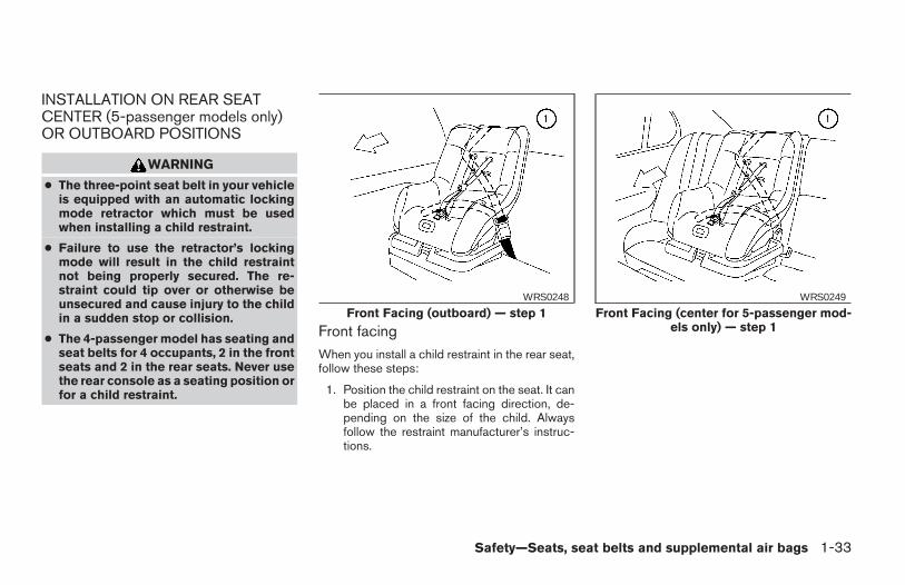
INSTALLATION ON REAR SEATCENTER (5-passenger models only)OR OUTBOARD POSITIONS
WARNING
● The three-point seat belt in your vehicleis equipped with an automatic lockingmode retractor which must be usedwhen installing a child restraint.
● Failure to use the retractor’s lockingmode will result in the child restraintnot being properly secured. The re-straint could tip over or otherwise beunsecured and cause injury to the childin a sudden stop or collision.
● The 4-passenger model has seating andseat belts for 4 occupants, 2 in the frontseats and 2 in the rear seats. Never usethe rear console as a seating position orfor a child restraint.
Front facingWhen you install a child restraint in the rear seat,follow these steps:
1. Position the child restraint on the seat. It canbe placed in a front facing direction, de-pending on the size of the child. Alwaysfollow the restraint manufacturer’s instruc-tions.
Front Facing (outboard) — step 1WRS0248
Front Facing (center for 5-passenger mod-els only) — step 1
WRS0249
Safety—Seats, seat belts and supplemental air bags 1-33
Z REVIEW COPY:—2004 Maxima (max)Owners Manual (owners)—USA English (nna)10/07/03—tbrooks X
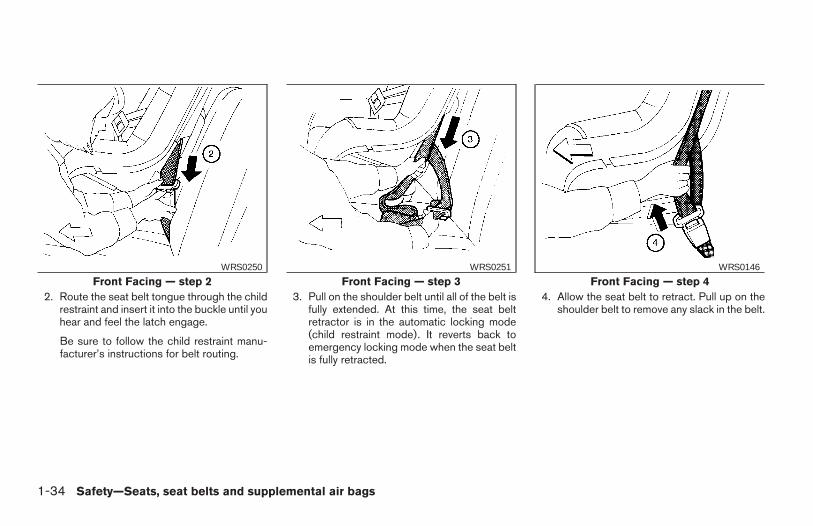
2. Route the seat belt tongue through the childrestraint and insert it into the buckle until youhear and feel the latch engage.
Be sure to follow the child restraint manu-facturer’s instructions for belt routing.
3. Pull on the shoulder belt until all of the belt isfully extended. At this time, the seat beltretractor is in the automatic locking mode(child restraint mode). It reverts back toemergency locking mode when the seat beltis fully retracted.
4. Allow the seat belt to retract. Pull up on theshoulder belt to remove any slack in the belt.
Front Facing — step 2WRS0250
Front Facing — step 3WRS0251
Front Facing — step 4WRS0146
1-34 Safety—Seats, seat belts and supplemental air bags
Z REVIEW COPY:—2004 Maxima (max)Owners Manual (owners)—USA English (nna)10/07/03—tbrooks X
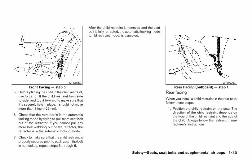
5. Before placing the child in the child restraint,use force to tilt the child restraint from sideto side, and tug it forward to make sure thatit is securely held in place. It should not movemore than 1 inch (25mm).
6. Check that the retractor is in the automaticlocking mode by trying to pull more seat beltout of the retractor. If you cannot pull anymore belt webbing out of the retractor, theretractor is in the automatic locking mode.
7. Check to make sure that the child restraint isproperly secured prior to each use. If the beltis not locked, repeat steps 3 through 6.
After the child restraint is removed and the seatbelt is fully retracted, the automatic locking mode(child restraint mode) is canceled.
Rear facingWhen you install a child restraint in the rear seat,follow these steps:
1. Position the child restraint on the seat. Thedirection of the child restraint depends onthe type of the child restraint and the size ofthe child. Always follow the restraint manu-facturer’s instructions.
Front Facing — step 5WRS0252
Rear Facing (outboard) — step 1WRS0261
Safety—Seats, seat belts and supplemental air bags 1-35
Z REVIEW COPY:—2004 Maxima (max)Owners Manual (owners)—USA English (nna)10/07/03—tbrooks X
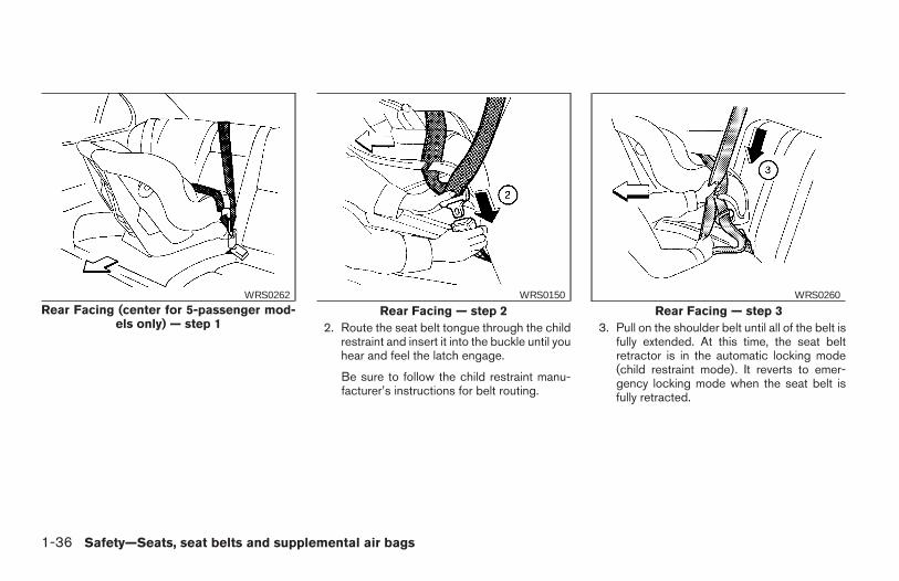
2. Route the seat belt tongue through the childrestraint and insert it into the buckle until youhear and feel the latch engage.
Be sure to follow the child restraint manu-facturer’s instructions for belt routing.
3. Pull on the shoulder belt until all of the belt isfully extended. At this time, the seat beltretractor is in the automatic locking mode(child restraint mode). It reverts to emer-gency locking mode when the seat belt isfully retracted.
Rear Facing (center for 5-passenger mod-els only) — step 1
WRS0262
Rear Facing — step 2WRS0150
Rear Facing — step 3WRS0260
1-36 Safety—Seats, seat belts and supplemental air bags
Z REVIEW COPY:—2004 Maxima (max)Owners Manual (owners)—USA English (nna)10/07/03—tbrooks X
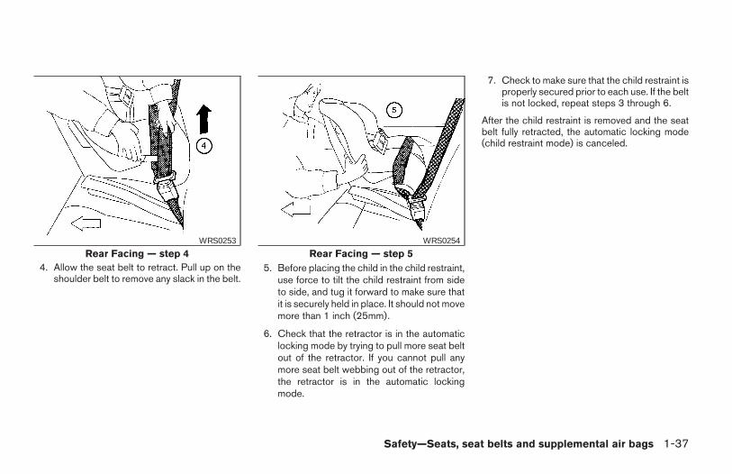
4. Allow the seat belt to retract. Pull up on theshoulder belt to remove any slack in the belt.
5. Before placing the child in the child restraint,use force to tilt the child restraint from sideto side, and tug it forward to make sure thatit is securely held in place. It should not movemore than 1 inch (25mm).
6. Check that the retractor is in the automaticlocking mode by trying to pull more seat beltout of the retractor. If you cannot pull anymore seat belt webbing out of the retractor,the retractor is in the automatic lockingmode.
7. Check to make sure that the child restraint isproperly secured prior to each use. If the beltis not locked, repeat steps 3 through 6.
After the child restraint is removed and the seatbelt fully retracted, the automatic locking mode(child restraint mode) is canceled.
Rear Facing — step 4WRS0253
Rear Facing — step 5WRS0254
Safety—Seats, seat belts and supplemental air bags 1-37
Z REVIEW COPY:—2004 Maxima (max)Owners Manual (owners)—USA English (nna)10/07/03—tbrooks X
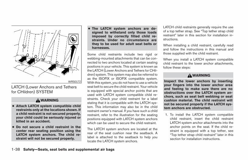
LATCH (Lower Anchors and Tethersfor CHildren) SYSTEM
WARNING
● Attach LATCH system compatible childrestraints only at the locations shown. Ifa child restraint is not secured properly,your child could be seriously injured orkilled in an accident.
● Do not secure a child restraint in thecenter rear seating position using theLATCH system anchors. The child re-straint will not be secured properly.
● The LATCH system anchors are de-signed to withstand only those loadsimposed by correctly fitted child re-straints. Under no circumstance arethey to be used for adult seat belts orharnesses.
Some child restraints include two rigid orwebbing-mounted attachments that can be con-nected to two anchors located at certain seatingpositions in your vehicle. This system is known asthe LATCH (Lower Anchors and Tethers for CHil-dren) system. This system may also be referred toas the ISOFIX or ISOFIX compatible system.With this system, you do not have to use a vehicleseat belt to secure the child restraint. Your vehicleis equipped with special anchor points that areused with LATCH system compatible child re-straints. Check your child restraint for a labelstating that it is compatible with the LATCH sys-tem. This information may also be in the childrestraint owner’s manual. If you have such a childrestraint, refer to the illustration for the seatingpositions equipped with LATCH system anchorswhich can be used to secure the child restraint.
The LATCH system anchors are located at therear of the seat cushion near the seatback. Alabel is attached to the seatback to help youlocate the LATCH system anchors.
LATCH child restraints generally require the useof a top tether strap. See “Top tether strap childrestraint” later in this section for installation in-structions.
When installing a child restraint, carefully readand follow the instructions in this manual andthose supplied with the child restraint.
When you install a LATCH system compatiblechild restraint to the lower anchor attachments,follow these steps:
WARNING
Inspect the lower anchors by insertingyour fingers into the lower anchor areaand feeling to make sure there are noobstructions over the LATCH system an-chors, such as seat belt webbing or seatcushion material. The child restraint willnot be secured properly if the LATCH sys-tem anchors are obstructed.
1. To install the LATCH system compatiblechild restraint, insert the child restraintLATCH system anchor attachments into theanchor points on the seat. If the child re-straint is equipped with a top tether, see“Top tether strap child restraint” later in thissection for installation instructions.
WRS0172
1-38 Safety—Seats, seat belts and supplemental air bags
Z REVIEW COPY:—2004 Maxima (max)Owners Manual (owners)—USA English (nna)10/07/03—tbrooks X
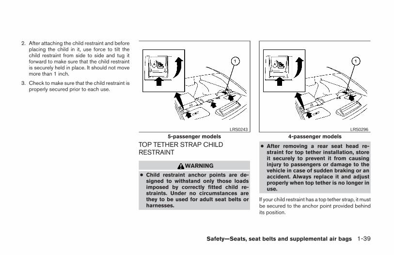
2. After attaching the child restraint and beforeplacing the child in it, use force to tilt thechild restraint from side to side and tug itforward to make sure that the child restraintis securely held in place. It should not movemore than 1 inch.
3. Check to make sure that the child restraint isproperly secured prior to each use.
TOP TETHER STRAP CHILDRESTRAINT
WARNING
● Child restraint anchor points are de-signed to withstand only those loadsimposed by correctly fitted child re-straints. Under no circumstances arethey to be used for adult seat belts orharnesses.
● After removing a rear seat head re-straint for top tether installation, storeit securely to prevent it from causinginjury to passengers or damage to thevehicle in case of sudden braking or anaccident. Always replace it and adjustproperly when top tether is no longer inuse.
If your child restraint has a top tether strap, it mustbe secured to the anchor point provided behindits position.
5-passenger modelsLRS0243
4-passenger modelsLRS0296
Safety—Seats, seat belts and supplemental air bags 1-39
Z REVIEW COPY:—2004 Maxima (max)Owners Manual (owners)—USA English (nna)10/07/03—tbrooks X
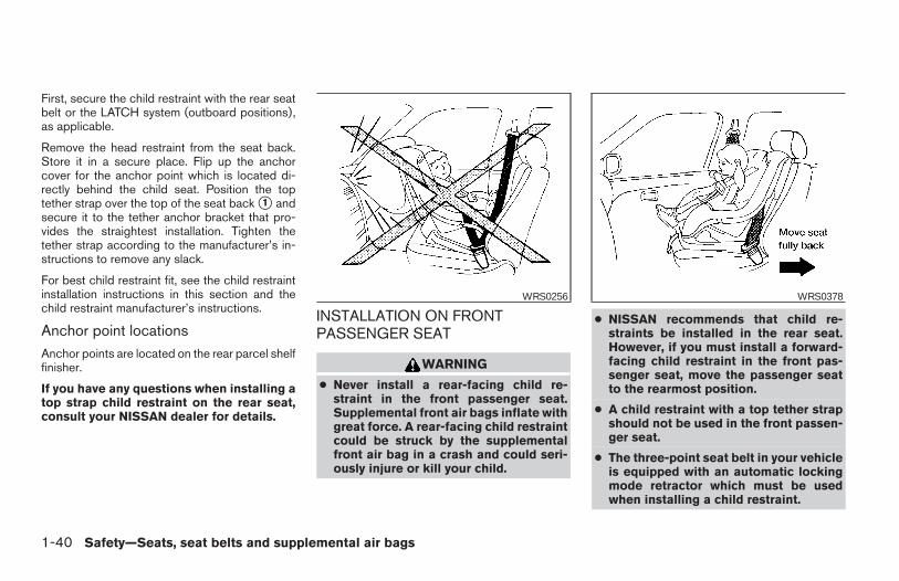
First, secure the child restraint with the rear seatbelt or the LATCH system (outboard positions),as applicable.
Remove the head restraint from the seat back.Store it in a secure place. Flip up the anchorcover for the anchor point which is located di-rectly behind the child seat. Position the toptether strap over the top of the seat back s1 andsecure it to the tether anchor bracket that pro-vides the straightest installation. Tighten thetether strap according to the manufacturer’s in-structions to remove any slack.
For best child restraint fit, see the child restraintinstallation instructions in this section and thechild restraint manufacturer’s instructions.
Anchor point locationsAnchor points are located on the rear parcel shelffinisher.
If you have any questions when installing atop strap child restraint on the rear seat,consult your NISSAN dealer for details.
INSTALLATION ON FRONTPASSENGER SEAT
WARNING
● Never install a rear-facing child re-straint in the front passenger seat.Supplemental front air bags inflate withgreat force. A rear-facing child restraintcould be struck by the supplementalfront air bag in a crash and could seri-ously injure or kill your child.
● NISSAN recommends that child re-straints be installed in the rear seat.However, if you must install a forward-facing child restraint in the front pas-senger seat, move the passenger seatto the rearmost position.
● A child restraint with a top tether strapshould not be used in the front passen-ger seat.
● The three-point seat belt in your vehicleis equipped with an automatic lockingmode retractor which must be usedwhen installing a child restraint.
WRS0256 WRS0378
1-40 Safety—Seats, seat belts and supplemental air bags
Z REVIEW COPY:—2004 Maxima (max)Owners Manual (owners)—USA English (nna)10/07/03—tbrooks X
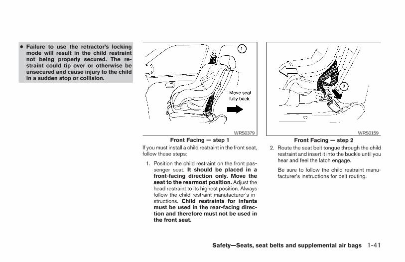
● Failure to use the retractor’s lockingmode will result in the child restraintnot being properly secured. The re-straint could tip over or otherwise beunsecured and cause injury to the childin a sudden stop or collision.
If you must install a child restraint in the front seat,follow these steps:
1. Position the child restraint on the front pas-senger seat. It should be placed in afront-facing direction only. Move theseat to the rearmost position. Adjust thehead restraint to its highest position. Alwaysfollow the child restraint manufacturer’s in-structions. Child restraints for infantsmust be used in the rear-facing direc-tion and therefore must not be used inthe front seat.
2. Route the seat belt tongue through the childrestraint and insert it into the buckle until youhear and feel the latch engage.
Be sure to follow the child restraint manu-facturer’s instructions for belt routing.
Front Facing — step 1WRS0379
Front Facing — step 2WRS0159
Safety—Seats, seat belts and supplemental air bags 1-41
Z REVIEW COPY:—2004 Maxima (max)Owners Manual (owners)—USA English (nna)10/07/03—tbrooks X
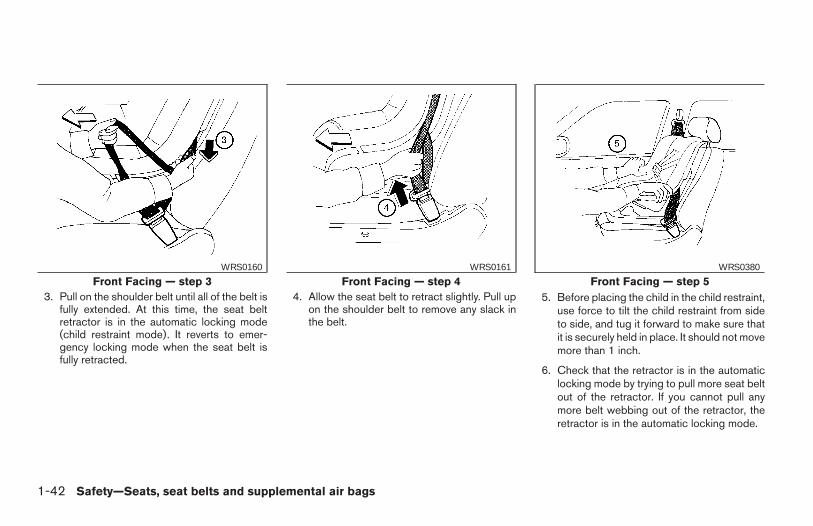
3. Pull on the shoulder belt until all of the belt isfully extended. At this time, the seat beltretractor is in the automatic locking mode(child restraint mode). It reverts to emer-gency locking mode when the seat belt isfully retracted.
4. Allow the seat belt to retract slightly. Pull upon the shoulder belt to remove any slack inthe belt.
5. Before placing the child in the child restraint,use force to tilt the child restraint from sideto side, and tug it forward to make sure thatit is securely held in place. It should not movemore than 1 inch.
6. Check that the retractor is in the automaticlocking mode by trying to pull more seat beltout of the retractor. If you cannot pull anymore belt webbing out of the retractor, theretractor is in the automatic locking mode.
Front Facing — step 3WRS0160
Front Facing — step 4WRS0161
Front Facing — step 5WRS0380
1-42 Safety—Seats, seat belts and supplemental air bags
Z REVIEW COPY:—2004 Maxima (max)Owners Manual (owners)—USA English (nna)10/07/03—tbrooks X
7. Check to make sure the child restraint isproperly secured prior to each use. If theseat belt is not locked, repeat steps 3through 6.
After the child restraint is removed and the seatbelt is fully retracted, the automatic locking mode(child restraint mode) is canceled.
Safety—Seats, seat belts and supplemental air bags 1-43
Z REVIEW COPY:—2004 Maxima (max)Owners Manual (owners)—USA English (nna)10/07/03—tbrooks X
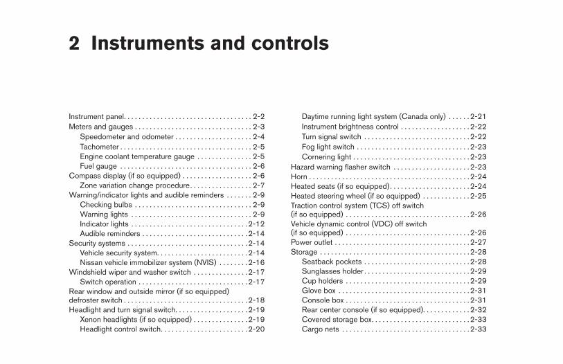
2 Instruments and controls
Instrument panel. . . . . . . . . . . . . . . . . . . . . . . . . . . . . . . . . . . 2-2Meters and gauges . . . . . . . . . . . . . . . . . . . . . . . . . . . . . . . . 2-3
Speedometer and odometer . . . . . . . . . . . . . . . . . . . . . 2-4Tachometer . . . . . . . . . . . . . . . . . . . . . . . . . . . . . . . . . . . . 2-5Engine coolant temperature gauge . . . . . . . . . . . . . . . 2-5Fuel gauge . . . . . . . . . . . . . . . . . . . . . . . . . . . . . . . . . . . . 2-6
Compass display (if so equipped) . . . . . . . . . . . . . . . . . . . 2-6Zone variation change procedure. . . . . . . . . . . . . . . . . 2-7
Warning/indicator lights and audible reminders . . . . . . . 2-9Checking bulbs . . . . . . . . . . . . . . . . . . . . . . . . . . . . . . . . 2-9Warning lights . . . . . . . . . . . . . . . . . . . . . . . . . . . . . . . . . 2-9Indicator lights . . . . . . . . . . . . . . . . . . . . . . . . . . . . . . . .2-12Audible reminders . . . . . . . . . . . . . . . . . . . . . . . . . . . . .2-14
Security systems . . . . . . . . . . . . . . . . . . . . . . . . . . . . . . . . .2-14Vehicle security system. . . . . . . . . . . . . . . . . . . . . . . . . 2-14Nissan vehicle immobilizer system (NVIS) . . . . . . . . 2-16
Windshield wiper and washer switch . . . . . . . . . . . . . . . 2-17Switch operation . . . . . . . . . . . . . . . . . . . . . . . . . . . . . .2-17
Rear window and outside mirror (if so equipped)defroster switch . . . . . . . . . . . . . . . . . . . . . . . . . . . . . . . . . .2-18Headlight and turn signal switch. . . . . . . . . . . . . . . . . . . . 2-19
Xenon headlights (if so equipped) . . . . . . . . . . . . . . . 2-19Headlight control switch. . . . . . . . . . . . . . . . . . . . . . . . 2-20
Daytime running light system (Canada only) . . . . . . 2-21Instrument brightness control . . . . . . . . . . . . . . . . . . . 2-22Turn signal switch . . . . . . . . . . . . . . . . . . . . . . . . . . . . .2-22Fog light switch . . . . . . . . . . . . . . . . . . . . . . . . . . . . . . .2-23Cornering light . . . . . . . . . . . . . . . . . . . . . . . . . . . . . . . .2-23
Hazard warning flasher switch . . . . . . . . . . . . . . . . . . . . . 2-23Horn . . . . . . . . . . . . . . . . . . . . . . . . . . . . . . . . . . . . . . . . . . . .2-24Heated seats (if so equipped). . . . . . . . . . . . . . . . . . . . . . 2-24Heated steering wheel (if so equipped) . . . . . . . . . . . . . 2-25Traction control system (TCS) off switch(if so equipped) . . . . . . . . . . . . . . . . . . . . . . . . . . . . . . . . . .2-26Vehicle dynamic control (VDC) off switch(if so equipped) . . . . . . . . . . . . . . . . . . . . . . . . . . . . . . . . . .2-26Power outlet . . . . . . . . . . . . . . . . . . . . . . . . . . . . . . . . . . . . .2-27Storage . . . . . . . . . . . . . . . . . . . . . . . . . . . . . . . . . . . . . . . . .2-28
Seatback pockets . . . . . . . . . . . . . . . . . . . . . . . . . . . . .2-28Sunglasses holder . . . . . . . . . . . . . . . . . . . . . . . . . . . . .2-29Cup holders . . . . . . . . . . . . . . . . . . . . . . . . . . . . . . . . . .2-29Glove box . . . . . . . . . . . . . . . . . . . . . . . . . . . . . . . . . . . .2-31Console box . . . . . . . . . . . . . . . . . . . . . . . . . . . . . . . . . .2-31Rear center console (if so equipped). . . . . . . . . . . . . 2-32Covered storage box. . . . . . . . . . . . . . . . . . . . . . . . . . . 2-33Cargo nets . . . . . . . . . . . . . . . . . . . . . . . . . . . . . . . . . . .2-33
Z REVIEW COPY:—2004 Maxima (max)Owners Manual (owners)—USA English (nna)10/20/03—arosenma X
Windows . . . . . . . . . . . . . . . . . . . . . . . . . . . . . . . . . . . . . . . .2-34Power windows . . . . . . . . . . . . . . . . . . . . . . . . . . . . . . .2-34
Skyview™ roof (if so equipped) . . . . . . . . . . . . . . . . . . . . . 2-36Sunroof (if so equipped). . . . . . . . . . . . . . . . . . . . . . . . . . . 2-36
Automatic sunroof . . . . . . . . . . . . . . . . . . . . . . . . . . . . .2-36Rear sun shade (if so equipped). . . . . . . . . . . . . . . . . . . . 2-38Interior light . . . . . . . . . . . . . . . . . . . . . . . . . . . . . . . . . . . . . .2-39Personal lights . . . . . . . . . . . . . . . . . . . . . . . . . . . . . . . . . . .2-40
Front . . . . . . . . . . . . . . . . . . . . . . . . . . . . . . . . . . . . . . . . .2-40Rear . . . . . . . . . . . . . . . . . . . . . . . . . . . . . . . . . . . . . . . . .2-41
Trunk light . . . . . . . . . . . . . . . . . . . . . . . . . . . . . . . . . . . . . . .2-41
HomelinkT universal transceiver . . . . . . . . . . . . . . . . . . . . 2-42Programming HomeLinkT. . . . . . . . . . . . . . . . . . . . . . . 2-42Programming HomeLinkT for Canadiancustomers . . . . . . . . . . . . . . . . . . . . . . . . . . . . . . . . . . . .2-44Operating the HomeLinkT universaltransceiver. . . . . . . . . . . . . . . . . . . . . . . . . . . . . . . . . . . .2-44Programming trouble-diagnosis . . . . . . . . . . . . . . . . . 2-44Clearing the programmed information . . . . . . . . . . . . 2-44Reprogramming a single HomeLinkT button . . . . . . 2-44If your vehicle is stolen . . . . . . . . . . . . . . . . . . . . . . . . . 2-45
Z REVIEW COPY:—2004 Maxima (max)Owners Manual (owners)—USA English (nna)10/20/03—arosenma X
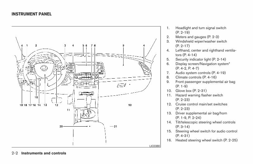
1. Headlight and turn signal switch(P. 2-19)
2. Meters and gauges (P. 2-3)3. Windshield wiper/washer switch
(P. 2-17)4. Lefthand, center and righthand ventila-
tors (P. 4-14)5. Security indicator light (P. 2-14)6. Display screen/Navigation system*
(P. 4-2, P. 4-7)7. Audio system controls (P. 4-19)8. Climate controls (P. 4-16)9. Front passenger supplemental air bag
(P. 1-9)10. Glove box (P. 2-31)11. Hazard warning flasher switch
(P. 2-23)12. Cruise control main/set switches
(P. 2-23)13. Driver supplemental air bag/horn
(P. 1-9, P. 2-24)14. Tilt/telescopic steering wheel controls
(P. 3-14)15. Steering wheel switch for audio control
(P. 4-31)16. Heated steering wheel switch (P. 2-25)
LIC0380
INSTRUMENT PANEL
2-2 Instruments and controls
Z REVIEW COPY:—2004 Maxima (max)Owners Manual (owners)—USA English (nna)10/20/03—arosenma X
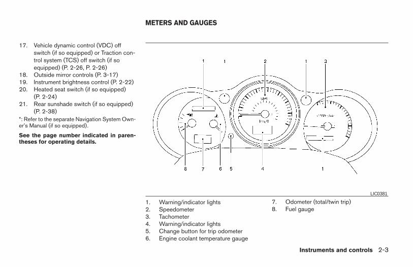
17. Vehicle dynamic control (VDC) offswitch (if so equipped) or Traction con-trol system (TCS) off switch (if soequipped) (P. 2-26, P. 2-26)
18. Outside mirror controls (P. 3-17)19. Instrument brightness control (P. 2-22)20. Heated seat switch (if so equipped)
(P. 2-24)21. Rear sunshade switch (if so equipped)
(P. 2-38)*: Refer to the separate Navigation System Own-er’s Manual (if so equipped).
See the page number indicated in paren-theses for operating details.
1. Warning/indicator lights2. Speedometer3. Tachometer4. Warning/indicator lights5. Change button for trip odometer6. Engine coolant temperature gauge
7. Odometer (total/twin trip)8. Fuel gauge
LIC0381
METERS AND GAUGES
Instruments and controls 2-3
Z REVIEW COPY:—2004 Maxima (max)Owners Manual (owners)—USA English (nna)10/20/03—arosenma X
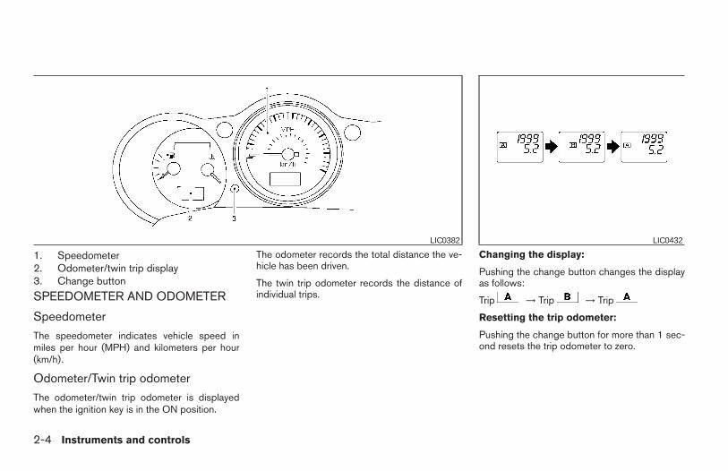
1. Speedometer2. Odometer/twin trip display3. Change button
SPEEDOMETER AND ODOMETER
Speedometer
The speedometer indicates vehicle speed inmiles per hour (MPH) and kilometers per hour(km/h).
Odometer/Twin trip odometer
The odometer/twin trip odometer is displayedwhen the ignition key is in the ON position.
The odometer records the total distance the ve-hicle has been driven.
The twin trip odometer records the distance ofindividual trips.
Changing the display:
Pushing the change button changes the displayas follows:
Trip → Trip → Trip
Resetting the trip odometer:
Pushing the change button for more than 1 sec-ond resets the trip odometer to zero.
LIC0382 LIC0432
2-4 Instruments and controls
Z REVIEW COPY:—2004 Maxima (max)Owners Manual (owners)—USA English (nna)10/07/03—tbrooks X
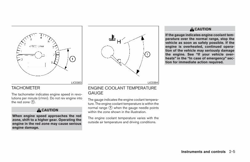
TACHOMETERThe tachometer indicates engine speed in revo-lutions per minute (r/min). Do not rev engine intothe red zone s1 .
CAUTION
When engine speed approaches the redzone, shift to a higher gear. Operating theengine in the red zone may cause seriousengine damage.
ENGINE COOLANT TEMPERATUREGAUGE
The gauge indicates the engine coolant tempera-ture. The engine coolant temperature is within thenormal range s1 when the gauge needle pointswithin the zone shown in the illustration.
The engine coolant temperature varies with theoutside air temperature and driving conditions.
CAUTION
If the gauge indicates engine coolant tem-perature over the normal range, stop thevehicle as soon as safely possible. If theengine is overheated, continued opera-tion of the vehicle may seriously damagethe engine. See “If your vehicle over-heats” in the “In case of emergency” sec-tion for immediate action required.
LIC0383 LIC0384
Instruments and controls 2-5
Z REVIEW COPY:—2004 Maxima (max)Owners Manual (owners)—USA English (nna)10/07/03—tbrooks X
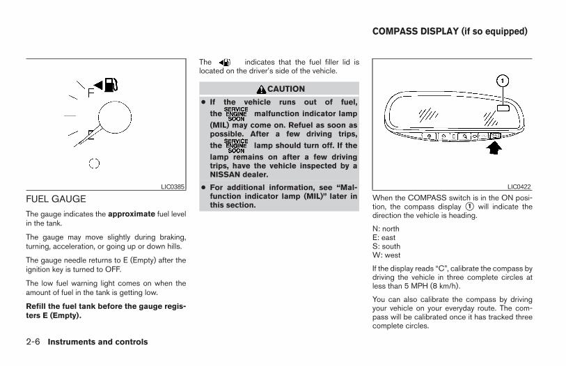
FUEL GAUGE
The gauge indicates the approximate fuel levelin the tank.
The gauge may move slightly during braking,turning, acceleration, or going up or down hills.
The gauge needle returns to E (Empty) after theignition key is turned to OFF.
The low fuel warning light comes on when theamount of fuel in the tank is getting low.
Refill the fuel tank before the gauge regis-ters E (Empty).
The indicates that the fuel filler lid islocated on the driver’s side of the vehicle.
CAUTION
● If the vehicle runs out of fuel,
the malfunction indicator lamp
(MIL) may come on. Refuel as soon aspossible. After a few driving trips,
the lamp should turn off. If the
lamp remains on after a few drivingtrips, have the vehicle inspected by aNISSAN dealer.
● For additional information, see “Mal-function indicator lamp (MIL)” later inthis section.
When the COMPASS switch is in the ON posi-tion, the compass display s1 will indicate thedirection the vehicle is heading.
N: northE: eastS: southW: west
If the display reads “C”, calibrate the compass bydriving the vehicle in three complete circles atless than 5 MPH (8 km/h).
You can also calibrate the compass by drivingyour vehicle on your everyday route. The com-pass will be calibrated once it has tracked threecomplete circles.
LIC0385 LIC0422
COMPASS DISPLAY (if so equipped)
2-6 Instruments and controls
Z REVIEW COPY:—2004 Maxima (max)Owners Manual (owners)—USA English (nna)10/07/03—tbrooks X
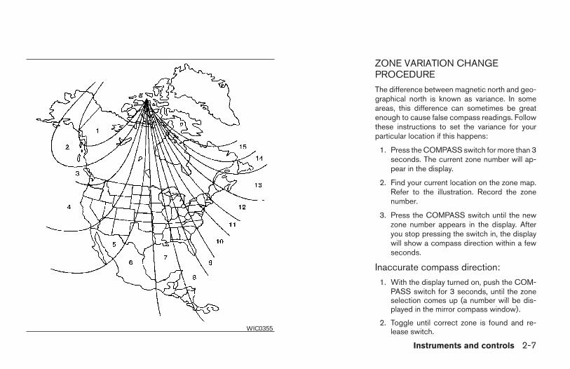
ZONE VARIATION CHANGEPROCEDURE
The difference between magnetic north and geo-graphical north is known as variance. In someareas, this difference can sometimes be greatenough to cause false compass readings. Followthese instructions to set the variance for yourparticular location if this happens:
1. Press the COMPASS switch for more than 3seconds. The current zone number will ap-pear in the display.
2. Find your current location on the zone map.Refer to the illustration. Record the zonenumber.
3. Press the COMPASS switch until the newzone number appears in the display. Afteryou stop pressing the switch in, the displaywill show a compass direction within a fewseconds.
Inaccurate compass direction:
1. With the display turned on, push the COM-PASS switch for 3 seconds, until the zoneselection comes up (a number will be dis-played in the mirror compass window).
2. Toggle until correct zone is found and re-lease switch.WIC0355
Instruments and controls 2-7
Z REVIEW COPY:—2004 Maxima (max)Owners Manual (owners)—USA English (nna)10/07/03—tbrooks X
3. The display will show all segments, and re-turn to the normal compass mode within 10seconds of no switch activity.
4. If the vehicle changes zone, repeat steps 1through 3. See map.
● If the compass deviates from the correctindication soon after repeated adjustment,have the compass checked at an authorizeddealer.
● The compass may not indicate the correctcompass point in tunnels or while driving upor down a steep hill. (The compass returnsto the correct compass point when the ve-hicle moves to an area where the geomag-netism is stabilized.)
CAUTION
● Do not install a ski rack, antenna, etc.,which are attached to the vehicle bymeans of a magnet. They affect the op-eration of the compass.
● When cleaning the mirror, use a papertowel or similar material dampenedwith glass cleaner. Do not spray glasscleaner directly on the mirror as it maycause the liquid cleaner to enter themirror housing.
2-8 Instruments and controls
Z REVIEW COPY:—2004 Maxima (max)Owners Manual (owners)—USA English (nna)10/07/03—tbrooks X
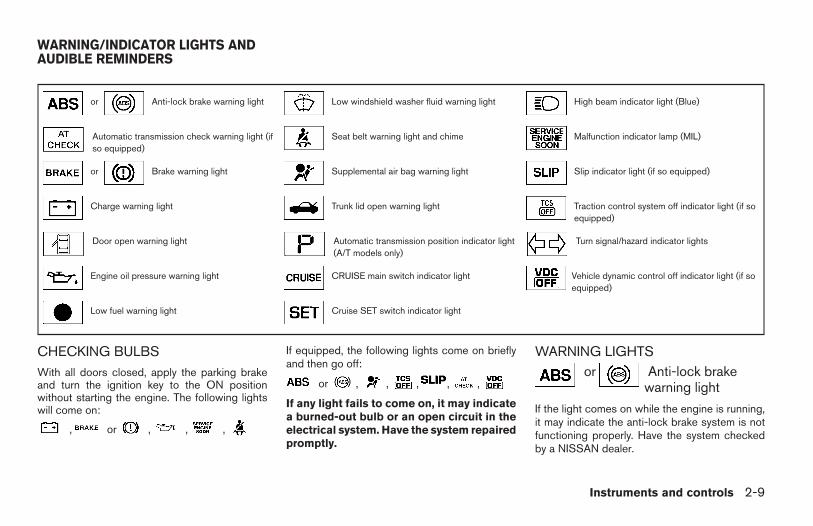
or Anti-lock brake warning light Low windshield washer fluid warning light High beam indicator light (Blue)
Automatic transmission check warning light (ifso equipped)
Seat belt warning light and chime Malfunction indicator lamp (MIL)
or Brake warning light Supplemental air bag warning light Slip indicator light (if so equipped)
Charge warning light Trunk lid open warning light Traction control system off indicator light (if soequipped)
Door open warning light Automatic transmission position indicator light(A/T models only)
Turn signal/hazard indicator lights
Engine oil pressure warning light CRUISE main switch indicator light Vehicle dynamic control off indicator light (if soequipped)
Low fuel warning light Cruise SET switch indicator light
CHECKING BULBSWith all doors closed, apply the parking brakeand turn the ignition key to the ON positionwithout starting the engine. The following lightswill come on:
, or , , ,
If equipped, the following lights come on brieflyand then go off:
or , , , , ,
If any light fails to come on, it may indicatea burned-out bulb or an open circuit in theelectrical system. Have the system repairedpromptly.
WARNING LIGHTSor Anti-lock brake
warning light
If the light comes on while the engine is running,it may indicate the anti-lock brake system is notfunctioning properly. Have the system checkedby a NISSAN dealer.
WARNING/INDICATOR LIGHTS ANDAUDIBLE REMINDERS
Instruments and controls 2-9
Z REVIEW COPY:—2004 Maxima (max)Owners Manual (owners)—USA English (nna)10/20/03—skoniecz X
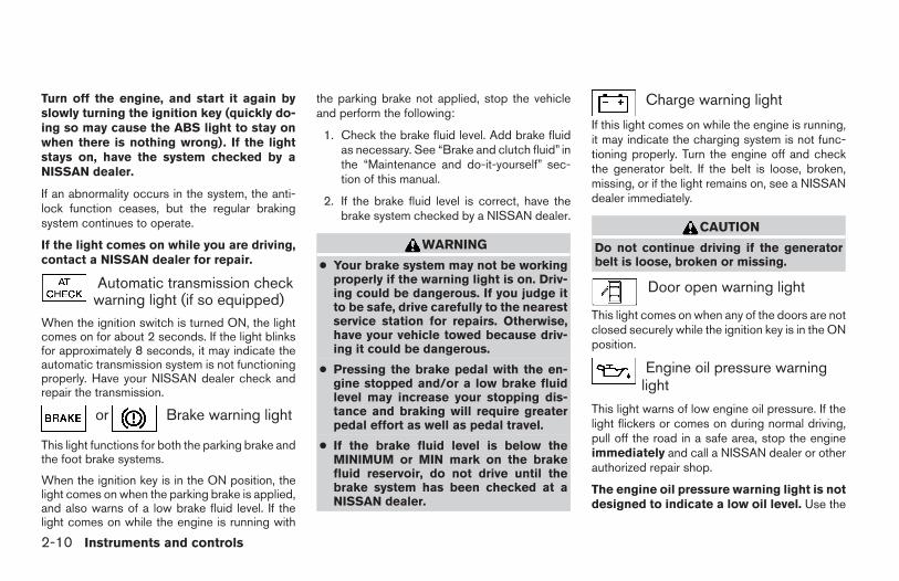
Turn off the engine, and start it again byslowly turning the ignition key (quickly do-ing so may cause the ABS light to stay onwhen there is nothing wrong). If the lightstays on, have the system checked by aNISSAN dealer.
If an abnormality occurs in the system, the anti-lock function ceases, but the regular brakingsystem continues to operate.
If the light comes on while you are driving,contact a NISSAN dealer for repair.
Automatic transmission checkwarning light (if so equipped)
When the ignition switch is turned ON, the lightcomes on for about 2 seconds. If the light blinksfor approximately 8 seconds, it may indicate theautomatic transmission system is not functioningproperly. Have your NISSAN dealer check andrepair the transmission.
or Brake warning light
This light functions for both the parking brake andthe foot brake systems.
When the ignition key is in the ON position, thelight comes on when the parking brake is applied,and also warns of a low brake fluid level. If thelight comes on while the engine is running with
the parking brake not applied, stop the vehicleand perform the following:
1. Check the brake fluid level. Add brake fluidas necessary. See “Brake and clutch fluid” inthe “Maintenance and do-it-yourself” sec-tion of this manual.
2. If the brake fluid level is correct, have thebrake system checked by a NISSAN dealer.
WARNING
● Your brake system may not be workingproperly if the warning light is on. Driv-ing could be dangerous. If you judge itto be safe, drive carefully to the nearestservice station for repairs. Otherwise,have your vehicle towed because driv-ing it could be dangerous.
● Pressing the brake pedal with the en-gine stopped and/or a low brake fluidlevel may increase your stopping dis-tance and braking will require greaterpedal effort as well as pedal travel.
● If the brake fluid level is below theMINIMUM or MIN mark on the brakefluid reservoir, do not drive until thebrake system has been checked at aNISSAN dealer.
Charge warning light
If this light comes on while the engine is running,it may indicate the charging system is not func-tioning properly. Turn the engine off and checkthe generator belt. If the belt is loose, broken,missing, or if the light remains on, see a NISSANdealer immediately.
CAUTION
Do not continue driving if the generatorbelt is loose, broken or missing.
Door open warning light
This light comes on when any of the doors are notclosed securely while the ignition key is in the ONposition.
Engine oil pressure warninglight
This light warns of low engine oil pressure. If thelight flickers or comes on during normal driving,pull off the road in a safe area, stop the engineimmediately and call a NISSAN dealer or otherauthorized repair shop.
The engine oil pressure warning light is notdesigned to indicate a low oil level. Use the
2-10 Instruments and controls
Z REVIEW COPY:—2004 Maxima (max)Owners Manual (owners)—USA English (nna)10/07/03—tbrooks X
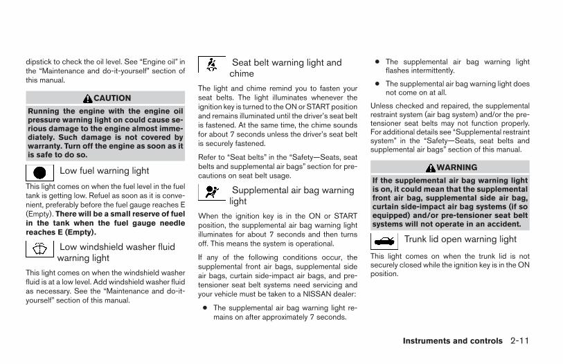
dipstick to check the oil level. See “Engine oil” inthe “Maintenance and do-it-yourself” section ofthis manual.
CAUTION
Running the engine with the engine oilpressure warning light on could cause se-rious damage to the engine almost imme-diately. Such damage is not covered bywarranty. Turn off the engine as soon as itis safe to do so.
Low fuel warning light
This light comes on when the fuel level in the fueltank is getting low. Refuel as soon as it is conve-nient, preferably before the fuel gauge reaches E(Empty). There will be a small reserve of fuelin the tank when the fuel gauge needlereaches E (Empty).
Low windshield washer fluidwarning light
This light comes on when the windshield washerfluid is at a low level. Add windshield washer fluidas necessary. See the “Maintenance and do-it-yourself” section of this manual.
Seat belt warning light andchime
The light and chime remind you to fasten yourseat belts. The light illuminates whenever theignition key is turned to the ON or START positionand remains illuminated until the driver’s seat beltis fastened. At the same time, the chime soundsfor about 7 seconds unless the driver’s seat beltis securely fastened.
Refer to “Seat belts” in the “Safety—Seats, seatbelts and supplemental air bags” section for pre-cautions on seat belt usage.
Supplemental air bag warninglight
When the ignition key is in the ON or STARTposition, the supplemental air bag warning lightilluminates for about 7 seconds and then turnsoff. This means the system is operational.
If any of the following conditions occur, thesupplemental front air bags, supplemental sideair bags, curtain side-impact air bags, and pre-tensioner seat belt systems need servicing andyour vehicle must be taken to a NISSAN dealer:
● The supplemental air bag warning light re-mains on after approximately 7 seconds.
● The supplemental air bag warning lightflashes intermittently.
● The supplemental air bag warning light doesnot come on at all.
Unless checked and repaired, the supplementalrestraint system (air bag system) and/or the pre-tensioner seat belts may not function properly.For additional details see “Supplemental restraintsystem” in the “Safety—Seats, seat belts andsupplemental air bags” section of this manual.
WARNING
If the supplemental air bag warning lightis on, it could mean that the supplementalfront air bag, supplemental side air bag,curtain side-impact air bag systems (if soequipped) and/or pre-tensioner seat beltsystems will not operate in an accident.
Trunk lid open warning light
This light comes on when the trunk lid is notsecurely closed while the ignition key is in the ONposition.
Instruments and controls 2-11
Z REVIEW COPY:—2004 Maxima (max)Owners Manual (owners)—USA English (nna)10/07/03—tbrooks X
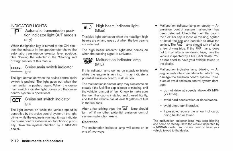
INDICATOR LIGHTSAutomatic transmission posi-tion indicator light (A/T modelsonly)
When the ignition key is turned to the ON posi-tion, the indicator in the speedometer shows theautomatic transmission selector lever position.See “Driving the vehicle” in the “Starting anddriving” section of this manual.
Cruise main switch indicatorlight
The light comes on when the cruise control mainswitch is pushed. The light goes out when themain switch is pushed again. When the cruisemain switch indicator light comes on, the cruisecontrol system is operational.
Cruise set switch indicatorlight
The light comes on while the vehicle speed iscontrolled by the cruise control system. If the lightblinks while the engine is running, it may indicatethe cruise control system is not functioning prop-erly. Have the system checked by a NISSANdealer.
High beam indicator light(Blue)
This blue light comes on when the headlight highbeams are on and goes out when the low beamsare selected.
The high beam indicator light also comes onwhen the passing signal is activated.
Malfunction indicator lamp(MIL)
If this indicator lamp comes on steady or blinkswhile the engine is running, it may indicate apotential emission control malfunction.
The malfunction indicator lamp may also come onsteady if the fuel filler cap is loose or missing, or ifthe vehicle runs out of fuel. Check to make surethe fuel filler cap is installed and closed tightly,and that the vehicle has at least 3 gallons of fuelin the fuel tank.
After a few driving trips, the lamp shouldturn off if no other potential emission controlsystem malfunction exists.
Operation
The malfunction indicator lamp will come on inone of two ways:
● Malfunction indicator lamp on steady — Anemission control system malfunction hasbeen detected. Check the fuel filler cap. Ifthe fuel filler cap is loose or missing, tightenor install the cap and continue to drive thevehicle. The lamp should turn off aftera few driving trips. If the lamp doesnot turn off after a few driving trips, have thevehicle inspected by a NISSAN dealer. Youdo not need to have your vehicle towed tothe dealer.
● Malfunction indicator lamp blinking — Anengine misfire has been detected which maydamage the emission control system. To re-duce or avoid emission control system dam-age:
– do not drive at speeds above 45 MPH(72 km/h).
– avoid hard acceleration or deceleration.
– avoid steep uphill grades.
– if possible, reduce the amount of cargobeing hauled or towed.
The malfunction indicator lamp may stop blinkingand come on steady. Have the vehicle inspected bya NISSAN dealer. You do not need to have yourvehicle towed to the dealer.
2-12 Instruments and controls
Z REVIEW COPY:—2004 Maxima (max)Owners Manual (owners)—USA English (nna)10/20/03—skoniecz X
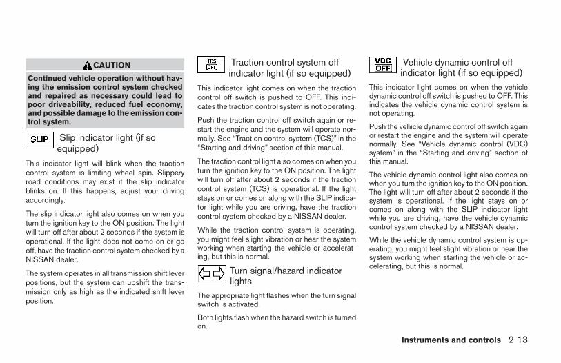
CAUTION
Continued vehicle operation without hav-ing the emission control system checkedand repaired as necessary could lead topoor driveability, reduced fuel economy,and possible damage to the emission con-trol system.
Slip indicator light (if soequipped)
This indicator light will blink when the tractioncontrol system is limiting wheel spin. Slipperyroad conditions may exist if the slip indicatorblinks on. If this happens, adjust your drivingaccordingly.
The slip indicator light also comes on when youturn the ignition key to the ON position. The lightwill turn off after about 2 seconds if the system isoperational. If the light does not come on or gooff, have the traction control system checked by aNISSAN dealer.
The system operates in all transmission shift leverpositions, but the system can upshift the trans-mission only as high as the indicated shift leverposition.
Traction control system offindicator light (if so equipped)
This indicator light comes on when the tractioncontrol off switch is pushed to OFF. This indi-cates the traction control system is not operating.
Push the traction control off switch again or re-start the engine and the system will operate nor-mally. See “Traction control system (TCS)” in the“Starting and driving” section of this manual.
The traction control light also comes on when youturn the ignition key to the ON position. The lightwill turn off after about 2 seconds if the tractioncontrol system (TCS) is operational. If the lightstays on or comes on along with the SLIP indica-tor light while you are driving, have the tractioncontrol system checked by a NISSAN dealer.
While the traction control system is operating,you might feel slight vibration or hear the systemworking when starting the vehicle or accelerat-ing, but this is normal.
Turn signal/hazard indicatorlights
The appropriate light flashes when the turn signalswitch is activated.
Both lights flash when the hazard switch is turnedon.
Vehicle dynamic control offindicator light (if so equipped)
This indicator light comes on when the vehicledynamic control off switch is pushed to OFF. Thisindicates the vehicle dynamic control system isnot operating.
Push the vehicle dynamic control off switch againor restart the engine and the system will operatenormally. See “Vehicle dynamic control (VDC)system” in the “Starting and driving” section ofthis manual.
The vehicle dynamic control light also comes onwhen you turn the ignition key to the ON position.The light will turn off after about 2 seconds if thesystem is operational. If the light stays on orcomes on along with the SLIP indicator lightwhile you are driving, have the vehicle dynamiccontrol system checked by a NISSAN dealer.
While the vehicle dynamic control system is op-erating, you might feel slight vibration or hear thesystem working when starting the vehicle or ac-celerating, but this is normal.
Instruments and controls 2-13
Z REVIEW COPY:—2004 Maxima (max)Owners Manual (owners)—USA English (nna)10/07/03—tbrooks X
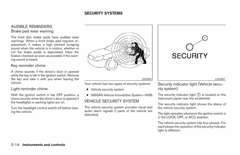
AUDIBLE REMINDERSBrake pad wear warningThe front disc brake pads have audible wearwarnings. When a front brake pad requires re-placement, it makes a high pitched scrapingsound when the vehicle is in motion, whether ornot the brake pedal is depressed. Have thebrakes checked as soon as possible if the warn-ing sound is heard.
Key reminder chimeA chime sounds if the driver’s door is openedwhile the key is left in the ignition switch. Removethe key and take it with you when leaving thevehicle.
Light reminder chimeWith the ignition switch in the OFF position, achime sounds when the driver’s door is opened ifthe headlights or parking lights are on.
Turn the headlight control switch off before leav-ing the vehicle.
Your vehicle has two types of security systems:
● Vehicle security system
● NISSAN Vehicle Immobilizer System—NVIS
VEHICLE SECURITY SYSTEMThe vehicle security system provides visual andaudio alarm signals if parts of the vehicle aredisturbed.
Security indicator light (Vehicle secu-rity system)The security indicator light s1 is located on theinstrument panel near the windshield.
The security indicator light shows the status ofthe vehicle security system.
The light operates whenever the ignition switch isin the LOCK, OFF, or ACC position.
The vehicle security system has four phases. Foreach phase the operation of the security indicatorlight is different.
LIC0301 LIC0387
SECURITY SYSTEMS
2-14 Instruments and controls
Z REVIEW COPY:—2004 Maxima (max)Owners Manual (owners)—USA English (nna)10/07/03—tbrooks X
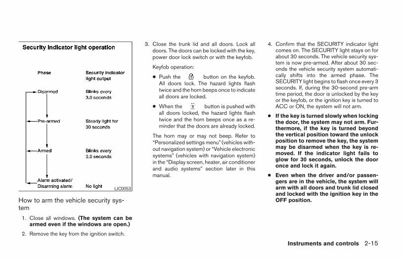
How to arm the vehicle security sys-tem
1. Close all windows. (The system can bearmed even if the windows are open.)
2. Remove the key from the ignition switch.
3. Close the trunk lid and all doors. Lock alldoors. The doors can be locked with the key,power door lock switch or with the keyfob.
Keyfob operation:
● Push the button on the keyfob.All doors lock. The hazard lights flashtwice and the horn beeps once to indicateall doors are locked.
● When the button is pushed withall doors locked, the hazard lights flashtwice and the horn beeps once as a re-minder that the doors are already locked.
The horn may or may not beep. Refer to“Personalized settings menu” (vehicles with-out navigation system) or “Vehicle electronicsystems” (vehicles with navigation system)in the “Display screen, heater, air conditionerand audio systems” section later in thismanual.
4. Confirm that the SECURITY indicator lightcomes on. The SECURITY light stays on forabout 30 seconds. The vehicle security sys-tem is now pre-armed. After about 30 sec-onds the vehicle security system automati-cally shifts into the armed phase. TheSECURITY light begins to flash once every 3seconds. If, during the 30-second pre-armtime period, the door is unlocked by the keyor the keyfob, or the ignition key is turned toACC or ON, the system will not arm.
● If the key is turned slowly when lockingthe door, the system may not arm. Fur-thermore, if the key is turned beyondthe vertical position toward the unlockposition to remove the key, the systemmay be disarmed when the key is re-moved. If the indicator light fails toglow for 30 seconds, unlock the dooronce and lock it again.
● Even when the driver and/or passen-gers are in the vehicle, the system willarm with all doors and trunk lid closedand locked with the ignition key in theOFF position.
LIC0053
Instruments and controls 2-15
Z REVIEW COPY:—2004 Maxima (max)Owners Manual (owners)—USA English (nna)10/07/03—tbrooks X
Vehicle security system activationThe vehicle security system will give the followingalarm:
● The headlights blink and the horn soundsintermittently.
● The alarm automatically turns off after ap-proximately 1 minute. However, the alarmreactivates if the vehicle is tampered withagain. The alarm can be shut off by unlockinga door with the key, or by pressing thebutton on the keyfob.
The alarm is activated by:
● opening the door or trunk lid without usingthe key or keyfob (even if the door is un-locked by releasing the door inside lockswitch) or opening the trunk lid by operatingthe opener lever.
How to stop an activated alarmThe alarm stops only by unlocking a door with thekey, or by pressing the button on the key-fob.
NISSAN VEHICLE IMMOBILIZERSYSTEM (NVIS)The NISSAN Vehicle Immobilizer System (NVIS)will not allow the engine to start without the use ofa registered NVIS key.
If the engine fails to start using a registered NVISkey (for example, when interference is caused byanother NVIS key, an automated toll road deviceor automatic payment device on the key ring),restart the engine using the following proce-dures:
1. Leave the ignition switch in the ON positionfor approximately 5 seconds.
2. Turn the ignition switch to the OFF or LOCKposition, and wait approximately 5 seconds.
3. Repeat steps 1 and 2.
4. Restart the engine while holding the device(which may have caused the interference)separate from the registered NVIS key.
If the no start condition re-occurs, NISSAN rec-ommends placing the registered NVIS key on aseparate key ring to avoid interference from otherdevices.
Statement related to Section 15 of FCCRules for NISSAN Vehicle Immobilizer Sys-tem (CONT ASSY — IMMOBILIZER, ANTASSY — IMMOBILIZER)
This device complies with part 15 of theFCC Rules and RSS-210 of IndustryCanada. Operation is subject to the follow-ing two conditions;
(1) This device may not cause harmful in-terference, and (2) this device must acceptany interference received, including inter-ference that may cause undesired opera-tion of the device.
CHANGES OR MODIFICATIONS NOT EX-PRESSLY APPROVED BY THE MANUFAC-TURER FOR COMPLIANCE COULD VOIDTHE USER’S AUTHORITY TO OPERATETHE EQUIPMENT.
2-16 Instruments and controls
Z REVIEW COPY:—2004 Maxima (max)Owners Manual (owners)—USA English (nna)10/07/03—tbrooks X
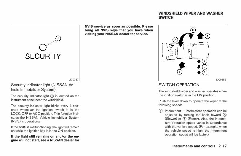
Security indicator light (NISSAN Ve-hicle Immobilizer System)
The security indicator light s1 is located on theinstrument panel near the windshield.
The security indicator light blinks every 3 sec-onds whenever the ignition switch is in theLOCK, OFF or ACC position. This function indi-cates the NISSAN Vehicle Immobilizer System(NVIS) is operational.
If the NVIS is malfunctioning, the light will remainon while the ignition key is in the ON position.
If the light still remains on and/or the en-gine will not start, see a NISSAN dealer for
NVIS service as soon as possible. Pleasebring all NVIS keys that you have whenvisiting your NISSAN dealer for service.
SWITCH OPERATION
The windshield wiper and washer operates whenthe ignition switch is in the ON position.
Push the lever down to operate the wiper at thefollowing speed:
s1 Intermittent — intermittent operation can beadjusted by turning the knob toward sA(Slower) or sB (Faster). Also, the intermit-tent operation speed varies in accordancewith the vehicle speed. (For example, whenthe vehicle speed is high, the intermittentoperation speed will be faster.)
LIC0387 LIC0386
WINDSHIELD WIPER AND WASHERSWITCH
Instruments and controls 2-17
Z REVIEW COPY:—2004 Maxima (max)Owners Manual (owners)—USA English (nna)10/07/03—tbrooks X
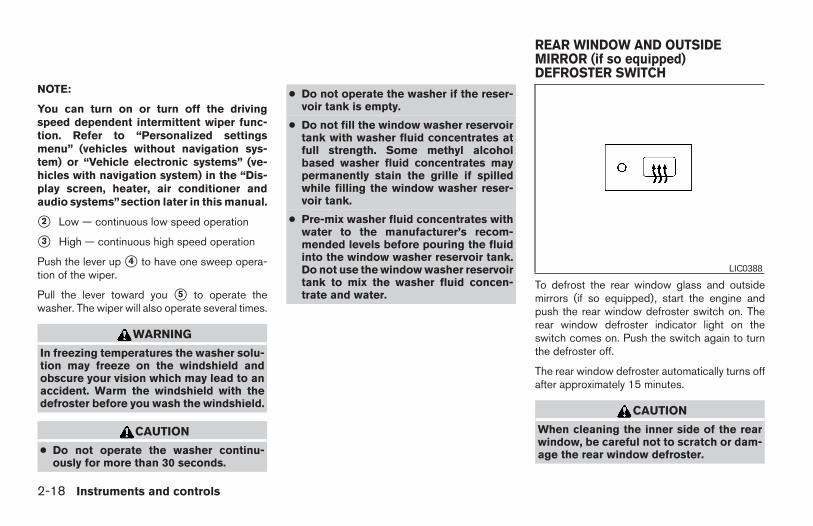
NOTE:
You can turn on or turn off the drivingspeed dependent intermittent wiper func-tion. Refer to “Personalized settingsmenu” (vehicles without navigation sys-tem) or “Vehicle electronic systems” (ve-hicles with navigation system) in the “Dis-play screen, heater, air conditioner andaudio systems”section later in this manual.
s2 Low — continuous low speed operation
s3 High — continuous high speed operation
Push the lever up s4 to have one sweep opera-tion of the wiper.
Pull the lever toward you s5 to operate thewasher. The wiper will also operate several times.
WARNING
In freezing temperatures the washer solu-tion may freeze on the windshield andobscure your vision which may lead to anaccident. Warm the windshield with thedefroster before you wash the windshield.
CAUTION
● Do not operate the washer continu-ously for more than 30 seconds.
● Do not operate the washer if the reser-voir tank is empty.
● Do not fill the window washer reservoirtank with washer fluid concentrates atfull strength. Some methyl alcoholbased washer fluid concentrates maypermanently stain the grille if spilledwhile filling the window washer reser-voir tank.
● Pre-mix washer fluid concentrates withwater to the manufacturer’s recom-mended levels before pouring the fluidinto the window washer reservoir tank.Do not use the window washer reservoirtank to mix the washer fluid concen-trate and water.
To defrost the rear window glass and outsidemirrors (if so equipped), start the engine andpush the rear window defroster switch on. Therear window defroster indicator light on theswitch comes on. Push the switch again to turnthe defroster off.
The rear window defroster automatically turns offafter approximately 15 minutes.
CAUTION
When cleaning the inner side of the rearwindow, be careful not to scratch or dam-age the rear window defroster.
LIC0388
REAR WINDOW AND OUTSIDEMIRROR (if so equipped)DEFROSTER SWITCH
2-18 Instruments and controls
Z REVIEW COPY:—2004 Maxima (max)Owners Manual (owners)—USA English (nna)10/07/03—tbrooks X
NOTE:
The top few rows of wires on the rear win-dow are not part of the rear window de-froster system. These wires make up theantenna for the audio system.
XENON HEADLIGHTS (if soequipped)
WARNING
cHIGH VOLTAGE
● When xenon headlights are on, theyproduce a high voltage. To prevent anelectric shock, never attempt to modifyor disassemble. Always have your xe-non headlights replaced at a NISSANdealer.
● Xenon headlights provide considerablymore light than conventional head-lights. If they are not correctly aimed,they might temporarily blind an oncom-ing driver or the driver ahead of you andcause a serious accident. If headlightsare not aimed correctly, immediatelytake your vehicle to a NISSAN dealerand have the headlights adjustedcorrectly.
When the xenon headlight is initially turned on, itsbrightness or color varies slightly. However, thecolor and brightness will soon stabilize.
● The life of xenon headlights will beshortened by frequent on-off opera-tion. It is generally desirable not to turnoff the headlights for short intervals
(for example, when the vehicle stops ata traffic signal). Even when the daytimerunning lights are active (Canada only),the xenon headlights do not turn on.This way the life of the xenon head-lights is not reduced.
● If the xenon headlight bulb is close toburning out, the brightness will drasti-cally decrease, the light will start blink-ing, or the color of the light will be-come reddish. If one or more of theabove signs appear, contact a NISSANdealer.
HEADLIGHT AND TURN SIGNALSWITCH
Instruments and controls 2-19
Z REVIEW COPY:—2004 Maxima (max)Owners Manual (owners)—USA English (nna)10/07/03—tbrooks X
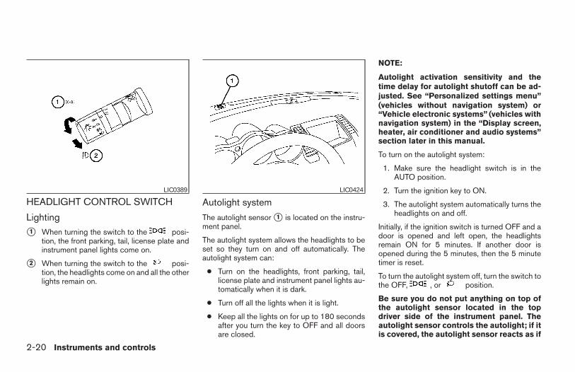
HEADLIGHT CONTROL SWITCH
Lighting
s1 When turning the switch to the posi-tion, the front parking, tail, license plate andinstrument panel lights come on.
s2 When turning the switch to the posi-tion, the headlights come on and all the otherlights remain on.
Autolight system
The autolight sensor s1 is located on the instru-ment panel.
The autolight system allows the headlights to beset so they turn on and off automatically. Theautolight system can:
● Turn on the headlights, front parking, tail,license plate and instrument panel lights au-tomatically when it is dark.
● Turn off all the lights when it is light.
● Keep all the lights on for up to 180 secondsafter you turn the key to OFF and all doorsare closed.
NOTE:
Autolight activation sensitivity and thetime delay for autolight shutoff can be ad-justed. See “Personalized settings menu”(vehicles without navigation system) or“Vehicle electronic systems” (vehicles withnavigation system) in the “Display screen,heater, air conditioner and audio systems”section later in this manual.
To turn on the autolight system:
1. Make sure the headlight switch is in theAUTO position.
2. Turn the ignition key to ON.
3. The autolight system automatically turns theheadlights on and off.
Initially, if the ignition switch is turned OFF and adoor is opened and left open, the headlightsremain ON for 5 minutes. If another door isopened during the 5 minutes, then the 5 minutetimer is reset.
To turn the autolight system off, turn the switch tothe OFF, , or position.
Be sure you do not put anything on top ofthe autolight sensor located in the topdriver side of the instrument panel. Theautolight sensor controls the autolight; if itis covered, the autolight sensor reacts as if
LIC0389 LIC0424
2-20 Instruments and controls
Z REVIEW COPY:—2004 Maxima (max)Owners Manual (owners)—USA English (nna)10/07/03—tbrooks X
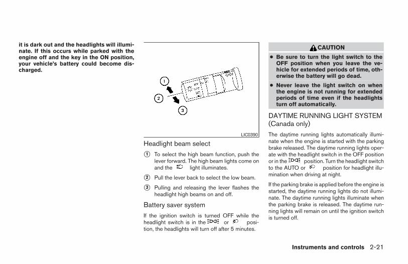
it is dark out and the headlights will illumi-nate. If this occurs while parked with theengine off and the key in the ON position,your vehicle’s battery could become dis-charged.
Headlight beam select
s1 To select the high beam function, push thelever forward. The high beam lights come onand the light illuminates.
s2 Pull the lever back to select the low beam.
s3 Pulling and releasing the lever flashes theheadlight high beams on and off.
Battery saver system
If the ignition switch is turned OFF while theheadlight switch is in the or posi-tion, the headlights will turn off after 5 minutes.
CAUTION
● Be sure to turn the light switch to theOFF position when you leave the ve-hicle for extended periods of time, oth-erwise the battery will go dead.
● Never leave the light switch on whenthe engine is not running for extendedperiods of time even if the headlightsturn off automatically.
DAYTIME RUNNING LIGHT SYSTEM(Canada only)
The daytime running lights automatically illumi-nate when the engine is started with the parkingbrake released. The daytime running lights oper-ate with the headlight switch in the OFF positionor in the position. Turn the headlight switchto the AUTO or position for headlight illu-mination when driving at night.
If the parking brake is applied before the engine isstarted, the daytime running lights do not illumi-nate. The daytime running lights illuminate whenthe parking brake is released. The daytime run-ning lights will remain on until the ignition switchis turned off.
LIC0390
Instruments and controls 2-21
Z REVIEW COPY:—2004 Maxima (max)Owners Manual (owners)—USA English (nna)10/07/03—tbrooks X
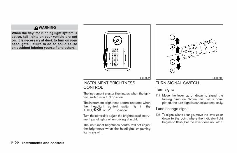
WARNING
When the daytime running light system isactive, tail lights on your vehicle are noton. It is necessary at dusk to turn on yourheadlights. Failure to do so could causean accident injuring yourself and others.
INSTRUMENT BRIGHTNESSCONTROLThe instrument cluster illuminates when the igni-tion switch is in ON position.
The instrument brightness control operates whenthe headlight control switch is in theAUTO, or position.
Turn the control to adjust the brightness of instru-ment panel lights when driving at night.
The instrument brightness control will not adjustthe brightness when the headlights or parkinglights are off.
TURN SIGNAL SWITCH
Turn signal
s1 Move the lever up or down to signal theturning direction. When the turn is com-pleted, the turn signals cancel automatically.
Lane change signal
s2 To signal a lane change, move the lever up ordown to the point where the indicator lightbegins to flash, but the lever does not latch.
LIC0392 LIC0391
2-22 Instruments and controls
Z REVIEW COPY:—2004 Maxima (max)Owners Manual (owners)—USA English (nna)10/07/03—tbrooks X
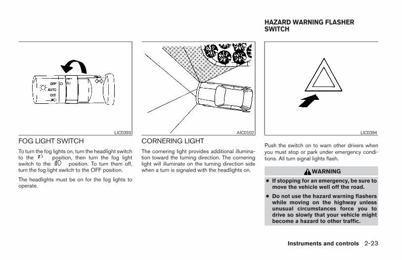
FOG LIGHT SWITCHTo turn the fog lights on, turn the headlight switchto the position, then turn the fog lightswitch to the position. To turn them off,turn the fog light switch to the OFF position.
The headlights must be on for the fog lights tooperate.
CORNERING LIGHTThe cornering light provides additional illumina-tion toward the turning direction. The corneringlight will illuminate on the turning direction sidewhen a turn is signaled with the headlights on.
Push the switch on to warn other drivers whenyou must stop or park under emergency condi-tions. All turn signal lights flash.
WARNING
● If stopping for an emergency, be sure tomove the vehicle well off the road.
● Do not use the hazard warning flasherswhile moving on the highway unlessunusual circumstances force you todrive so slowly that your vehicle mightbecome a hazard to other traffic.
LIC0393 AIC0102 LIC0394
HAZARD WARNING FLASHERSWITCH
Instruments and controls 2-23
Z REVIEW COPY:—2004 Maxima (max)Owners Manual (owners)—USA English (nna)10/07/03—tbrooks X
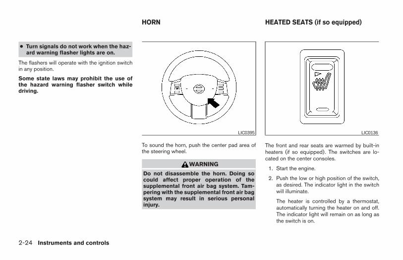
● Turn signals do not work when the haz-ard warning flasher lights are on.
The flashers will operate with the ignition switchin any position.
Some state laws may prohibit the use ofthe hazard warning flasher switch whiledriving.
To sound the horn, push the center pad area ofthe steering wheel.
WARNING
Do not disassemble the horn. Doing socould affect proper operation of thesupplemental front air bag system. Tam-pering with the supplemental front air bagsystem may result in serious personalinjury.
The front and rear seats are warmed by built-inheaters (if so equipped). The switches are lo-cated on the center consoles.
1. Start the engine.
2. Push the low or high position of the switch,as desired. The indicator light in the switchwill illuminate.
The heater is controlled by a thermostat,automatically turning the heater on and off.The indicator light will remain on as long asthe switch is on.
LIC0395 LIC0136
HORN HEATED SEATS (if so equipped)
2-24 Instruments and controls
Z REVIEW COPY:—2004 Maxima (max)Owners Manual (owners)—USA English (nna)10/07/03—tbrooks X
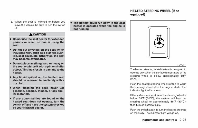
3. When the seat is warmed or before youleave the vehicle, be sure to turn the switchoff.
CAUTION
● Do not use the seat heater for extendedperiods or when no one is using theseat.
● Do not put anything on the seat whichinsulates heat, such as a blanket, cush-ion, seat cover, etc. Otherwise, the seatmay become overheated.
● Do not place anything hard or heavy onthe seat or pierce it with a pin or similarobject. This may result in damage to theheater.
● Any liquid spilled on the heated seatshould be removed immediately with adry cloth.
● When cleaning the seat, never usegasoline, benzine, thinner, or any simi-lar materials.
● If any abnormalities are found or theheated seat does not operate, turn theswitch off and have the system checkedby your NISSAN dealer.
● The battery could run down if the seatheater is operated while the engine isnot running.
The heated steering wheel system is designed tooperate only when the surface temperature of thesteering wheel is below approximately 68°F(20°C).
Push the heated steering wheel switch to warmthe steering wheel after the engine starts. Theindicator light will come on.
If the surface temperature of the steering wheel isbelow 68°F (20°C), the system will heat thesteering wheel to approximately 86°F (30°C),then turn off automatically.
Push the switch again to turn the heated steeringoff manually. The indicator light will go off.
LIC0421
HEATED STEERING WHEEL (if soequipped)
Instruments and controls 2-25
Z REVIEW COPY:—2004 Maxima (max)Owners Manual (owners)—USA English (nna)10/07/03—tbrooks X
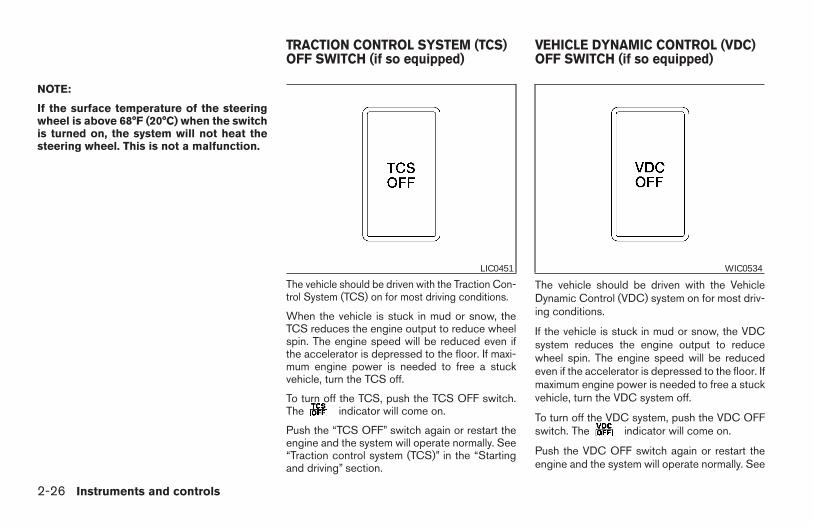
NOTE:
If the surface temperature of the steeringwheel is above 68°F (20°C) when the switchis turned on, the system will not heat thesteering wheel. This is not a malfunction.
The vehicle should be driven with the Traction Con-trol System (TCS) on for most driving conditions.
When the vehicle is stuck in mud or snow, theTCS reduces the engine output to reduce wheelspin. The engine speed will be reduced even ifthe accelerator is depressed to the floor. If maxi-mum engine power is needed to free a stuckvehicle, turn the TCS off.
To turn off the TCS, push the TCS OFF switch.The indicator will come on.
Push the “TCS OFF” switch again or restart theengine and the system will operate normally. See“Traction control system (TCS)” in the “Startingand driving” section.
The vehicle should be driven with the VehicleDynamic Control (VDC) system on for most driv-ing conditions.
If the vehicle is stuck in mud or snow, the VDCsystem reduces the engine output to reducewheel spin. The engine speed will be reducedeven if the accelerator is depressed to the floor. Ifmaximum engine power is needed to free a stuckvehicle, turn the VDC system off.
To turn off the VDC system, push the VDC OFFswitch. The indicator will come on.
Push the VDC OFF switch again or restart theengine and the system will operate normally. See
LIC0451 WIC0534
TRACTION CONTROL SYSTEM (TCS)OFF SWITCH (if so equipped)
VEHICLE DYNAMIC CONTROL (VDC)OFF SWITCH (if so equipped)
2-26 Instruments and controls
Z REVIEW COPY:—2004 Maxima (max)Owners Manual (owners)—USA English (nna)10/07/03—tbrooks X
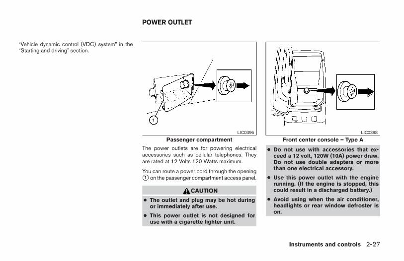
“Vehicle dynamic control (VDC) system” in the“Starting and driving” section.
The power outlets are for powering electricalaccessories such as cellular telephones. Theyare rated at 12 Volts 120 Watts maximum.
You can route a power cord through the openings1 on the passenger compartment access panel.
CAUTION
● The outlet and plug may be hot duringor immediately after use.
● This power outlet is not designed foruse with a cigarette lighter unit.
● Do not use with accessories that ex-ceed a 12 volt, 120W (10A) power draw.Do not use double adapters or morethan one electrical accessory.
● Use this power outlet with the enginerunning. (If the engine is stopped, thiscould result in a discharged battery.)
● Avoid using when the air conditioner,headlights or rear window defroster ison.
Passenger compartmentLIC0396
Front center console – Type ALIC0398
POWER OUTLET
Instruments and controls 2-27
Z REVIEW COPY:—2004 Maxima (max)Owners Manual (owners)—USA English (nna)10/07/03—tbrooks X
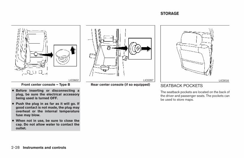
● Before inserting or disconnecting aplug, be sure the electrical accessorybeing used is turned OFF.
● Push the plug in as far as it will go. Ifgood contact is not made, the plug mayoverheat or the internal temperaturefuse may blow.
● When not in use, be sure to close thecap. Do not allow water to contact theoutlet.
SEATBACK POCKETSThe seatback pockets are located on the back ofthe driver and passenger seats. The pockets canbe used to store maps.
Front center console – Type BLIC0602
Rear center console (if so equipped)LIC0397 LIC0016
STORAGE
2-28 Instruments and controls
Z REVIEW COPY:—2004 Maxima (max)Owners Manual (owners)—USA English (nna)10/07/03—tbrooks X
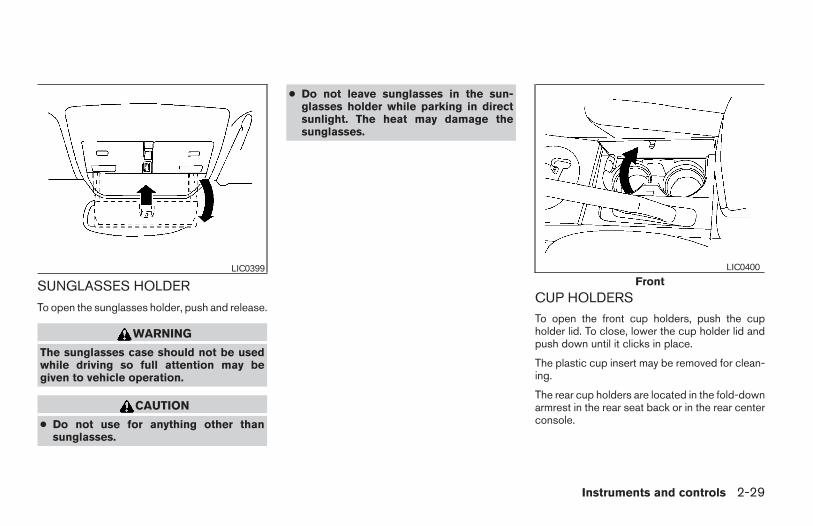
SUNGLASSES HOLDER
To open the sunglasses holder, push and release.
WARNING
The sunglasses case should not be usedwhile driving so full attention may begiven to vehicle operation.
CAUTION
● Do not use for anything other thansunglasses.
● Do not leave sunglasses in the sun-glasses holder while parking in directsunlight. The heat may damage thesunglasses.
CUP HOLDERSTo open the front cup holders, push the cupholder lid. To close, lower the cup holder lid andpush down until it clicks in place.
The plastic cup insert may be removed for clean-ing.
The rear cup holders are located in the fold-downarmrest in the rear seat back or in the rear centerconsole.
LIC0399Front
LIC0400
Instruments and controls 2-29
Z REVIEW COPY:—2004 Maxima (max)Owners Manual (owners)—USA English (nna)10/07/03—tbrooks X
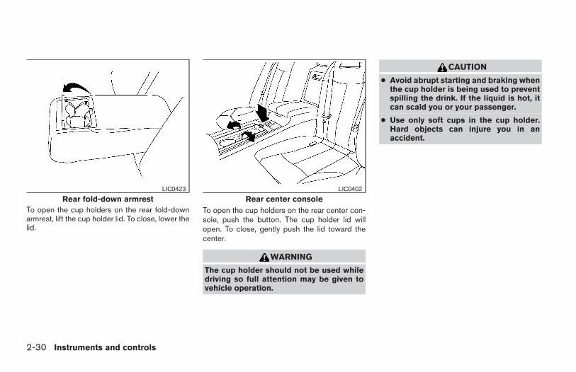
To open the cup holders on the rear fold-downarmrest, lift the cup holder lid. To close, lower thelid.
To open the cup holders on the rear center con-sole, push the button. The cup holder lid willopen. To close, gently push the lid toward thecenter.
WARNING
The cup holder should not be used whiledriving so full attention may be given tovehicle operation.
CAUTION
● Avoid abrupt starting and braking whenthe cup holder is being used to preventspilling the drink. If the liquid is hot, itcan scald you or your passenger.
● Use only soft cups in the cup holder.Hard objects can injure you in anaccident.
Rear fold-down armrestLIC0423
Rear center consoleLIC0402
2-30 Instruments and controls
Z REVIEW COPY:—2004 Maxima (max)Owners Manual (owners)—USA English (nna)10/07/03—tbrooks X
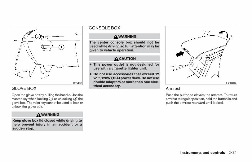
GLOVE BOXOpen the glove box by pulling the handle. Use themaster key when locking s1 or unlocking s2 theglove box. The valet key cannot be used to lock orunlock the glove box.
WARNING
Keep glove box lid closed while driving tohelp prevent injury in an accident or asudden stop.
CONSOLE BOX
WARNING
The center console box should not beused while driving so full attention may begiven to vehicle operation.
CAUTION
● This power outlet is not designed foruse with a cigarette lighter unit.
● Do not use accessories that exceed 12volt, 120W (10A) power draw. Do not usedouble adapters or more than one elec-trical accessory.
ArmrestPush the button to elevate the armrest. To returnarmrest to regular position, hold the button in andpush the armrest rearward until locked.
LIC0403 LIC0404
Instruments and controls 2-31
Z REVIEW COPY:—2004 Maxima (max)Owners Manual (owners)—USA English (nna)10/07/03—tbrooks X
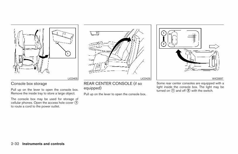
Console box storagePull up on the lever to open the console box.Remove the inside tray to store a large object.
The console box may be used for storage ofcellular phones. Open the access hole cover s1to route a cord to the power outlet.
REAR CENTER CONSOLE (if soequipped)Pull up on the lever to open the console box.
Some rear center consoles are equipped with alight inside the console box. The light may beturned on s1 and off s2 with the switch.
LIC0405 LIC0426 WIC0697
2-32 Instruments and controls
Z REVIEW COPY:—2004 Maxima (max)Owners Manual (owners)—USA English (nna)10/07/03—tbrooks X
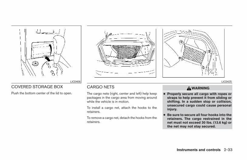
COVERED STORAGE BOXPush the bottom center of the lid to open.
CARGO NETS
The cargo nets (right, center and left) help keeppackages in the cargo area from moving aroundwhile the vehicle is in motion.
To install a cargo net, attach the hooks to theretainers.
To remove a cargo net, detach the hooks from theretainers.
WARNING
● Properly secure all cargo with ropes orstraps to help prevent it from sliding orshifting. In a sudden stop or collision,unsecured cargo could cause personalinjury.
● Be sure to secure all four hooks into theretainers. The cargo restrained in thenet must not exceed 30 lbs. (13.6 kg) orthe net may not stay secured.
LIC0406 LIC0425
Instruments and controls 2-33
Z REVIEW COPY:—2004 Maxima (max)Owners Manual (owners)—USA English (nna)10/07/03—tbrooks X
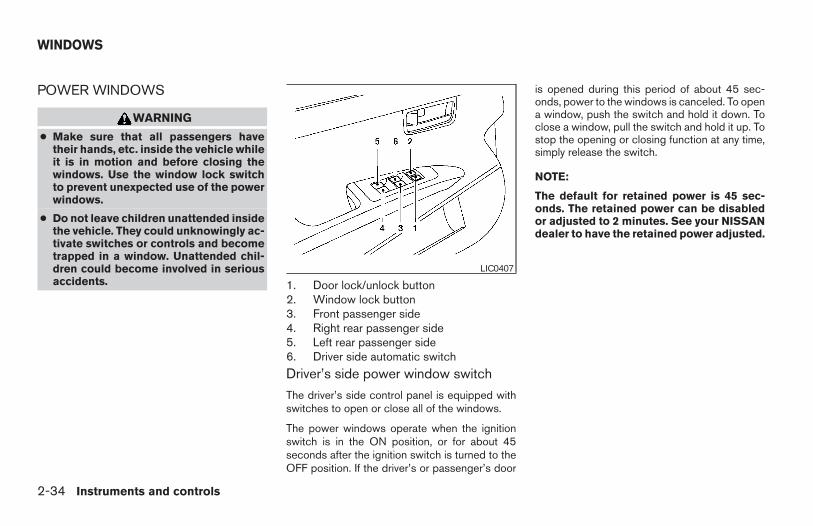
POWER WINDOWS
WARNING
● Make sure that all passengers havetheir hands, etc. inside the vehicle whileit is in motion and before closing thewindows. Use the window lock switchto prevent unexpected use of the powerwindows.
● Do not leave children unattended insidethe vehicle. They could unknowingly ac-tivate switches or controls and becometrapped in a window. Unattended chil-dren could become involved in seriousaccidents. 1. Door lock/unlock button
2. Window lock button3. Front passenger side4. Right rear passenger side5. Left rear passenger side6. Driver side automatic switch
Driver’s side power window switch
The driver’s side control panel is equipped withswitches to open or close all of the windows.
The power windows operate when the ignitionswitch is in the ON position, or for about 45seconds after the ignition switch is turned to theOFF position. If the driver’s or passenger’s door
is opened during this period of about 45 sec-onds, power to the windows is canceled. To opena window, push the switch and hold it down. Toclose a window, pull the switch and hold it up. Tostop the opening or closing function at any time,simply release the switch.
NOTE:
The default for retained power is 45 sec-onds. The retained power can be disabledor adjusted to 2 minutes. See your NISSANdealer to have the retained power adjusted.
LIC0407
WINDOWS
2-34 Instruments and controls
Z REVIEW COPY:—2004 Maxima (max)Owners Manual (owners)—USA English (nna)10/07/03—tbrooks X
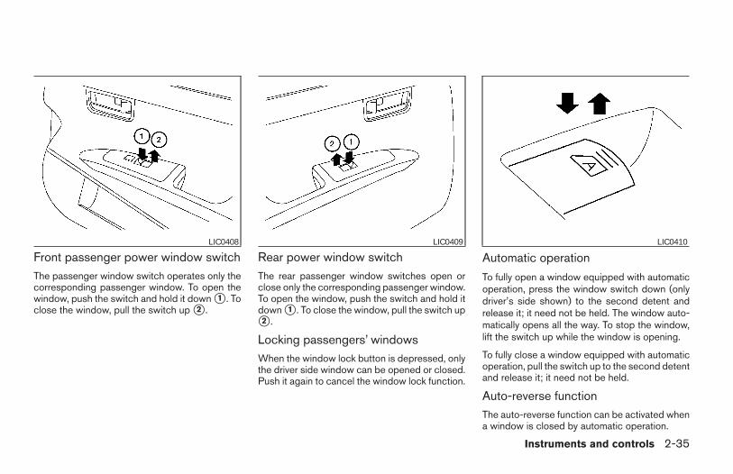
Front passenger power window switchThe passenger window switch operates only thecorresponding passenger window. To open thewindow, push the switch and hold it down s1 . Toclose the window, pull the switch up s2 .
Rear power window switchThe rear passenger window switches open orclose only the corresponding passenger window.To open the window, push the switch and hold itdown s1 . To close the window, pull the switch ups2 .
Locking passengers’ windowsWhen the window lock button is depressed, onlythe driver side window can be opened or closed.Push it again to cancel the window lock function.
Automatic operation
To fully open a window equipped with automaticoperation, press the window switch down (onlydriver’s side shown) to the second detent andrelease it; it need not be held. The window auto-matically opens all the way. To stop the window,lift the switch up while the window is opening.
To fully close a window equipped with automaticoperation, pull the switch up to the second detentand release it; it need not be held.
Auto-reverse functionThe auto-reverse function can be activated whena window is closed by automatic operation.
LIC0408 LIC0409 LIC0410
Instruments and controls 2-35
Z REVIEW COPY:—2004 Maxima (max)Owners Manual (owners)—USA English (nna)10/07/03—tbrooks X
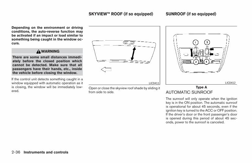
Depending on the environment or drivingconditions, the auto-reverse function maybe activated if an impact or load similar tosomething being caught in the window oc-curs.
WARNING
There are some small distances immedi-ately before the closed position whichcannot be detected. Make sure that allpassengers have their hands, etc., insidethe vehicle before closing the window.
If the control unit detects something caught in awindow equipped with automatic operation as itis closing, the window will be immediately low-ered.
Open or close the skyview roof shade by sliding itfrom side to side. AUTOMATIC SUNROOF
The sunroof will only operate when the ignitionkey is in the ON position. The automatic sunroofis operational for about 45 seconds, even if theignition key is turned to the ACC or OFF position.If the driver’s door or the front passenger’s dooris opened during this period of about 45 sec-onds, power to the sunroof is canceled.
LIC0411Type A
LIC0412
SKYVIEW™ ROOF (if so equipped) SUNROOF (if so equipped)
2-36 Instruments and controls
Z REVIEW COPY:—2004 Maxima (max)Owners Manual (owners)—USA English (nna)10/07/03—tbrooks X
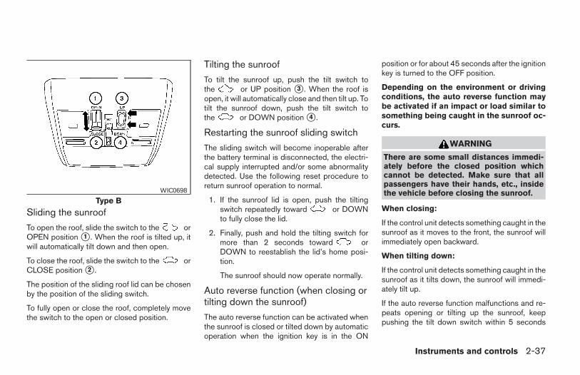
Sliding the sunroof
To open the roof, slide the switch to the orOPEN position s1 . When the roof is tilted up, itwill automatically tilt down and then open.
To close the roof, slide the switch to the orCLOSE position s2 .
The position of the sliding roof lid can be chosenby the position of the sliding switch.
To fully open or close the roof, completely movethe switch to the open or closed position.
Tilting the sunroof
To tilt the sunroof up, push the tilt switch tothe or UP position s3 . When the roof isopen, it will automatically close and then tilt up. Totilt the sunroof down, push the tilt switch tothe or DOWN position s4 .
Restarting the sunroof sliding switch
The sliding switch will become inoperable afterthe battery terminal is disconnected, the electri-cal supply interrupted and/or some abnormalitydetected. Use the following reset procedure toreturn sunroof operation to normal.
1. If the sunroof lid is open, push the tiltingswitch repeatedly toward or DOWNto fully close the lid.
2. Finally, push and hold the tilting switch formore than 2 seconds toward orDOWN to reestablish the lid’s home posi-tion.
The sunroof should now operate normally.
Auto reverse function (when closing ortilting down the sunroof)
The auto reverse function can be activated whenthe sunroof is closed or tilted down by automaticoperation when the ignition key is in the ON
position or for about 45 seconds after the ignitionkey is turned to the OFF position.
Depending on the environment or drivingconditions, the auto reverse function maybe activated if an impact or load similar tosomething being caught in the sunroof oc-curs.
WARNING
There are some small distances immedi-ately before the closed position whichcannot be detected. Make sure that allpassengers have their hands, etc., insidethe vehicle before closing the sunroof.
When closing:
If the control unit detects something caught in thesunroof as it moves to the front, the sunroof willimmediately open backward.
When tilting down:
If the control unit detects something caught in thesunroof as it tilts down, the sunroof will immedi-ately tilt up.
If the auto reverse function malfunctions and re-peats opening or tilting up the sunroof, keeppushing the tilt down switch within 5 seconds
Type BWIC0698
Instruments and controls 2-37
Z REVIEW COPY:—2004 Maxima (max)Owners Manual (owners)—USA English (nna)10/07/03—tbrooks X
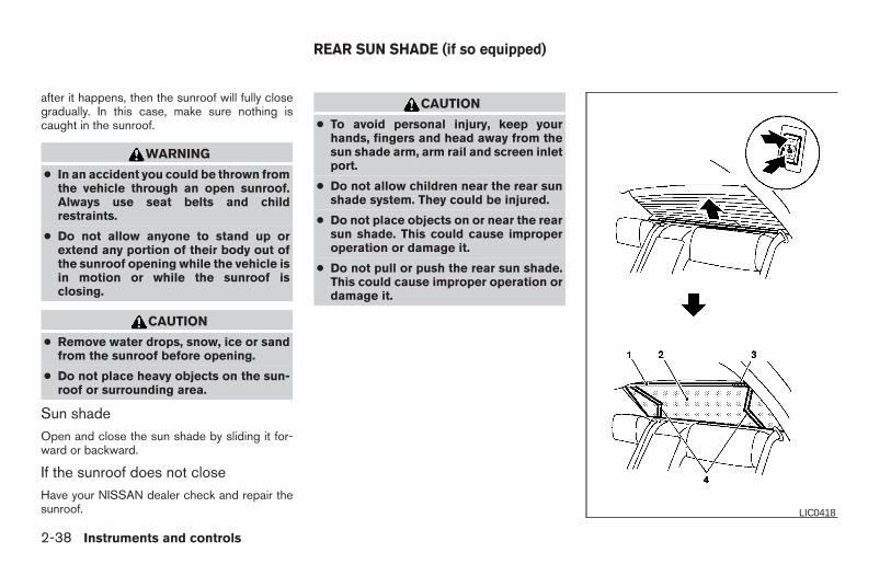
after it happens, then the sunroof will fully closegradually. In this case, make sure nothing iscaught in the sunroof.
WARNING
● In an accident you could be thrown fromthe vehicle through an open sunroof.Always use seat belts and childrestraints.
● Do not allow anyone to stand up orextend any portion of their body out ofthe sunroof opening while the vehicle isin motion or while the sunroof isclosing.
CAUTION
● Remove water drops, snow, ice or sandfrom the sunroof before opening.
● Do not place heavy objects on the sun-roof or surrounding area.
Sun shadeOpen and close the sun shade by sliding it for-ward or backward.
If the sunroof does not closeHave your NISSAN dealer check and repair thesunroof.
CAUTION
● To avoid personal injury, keep yourhands, fingers and head away from thesun shade arm, arm rail and screen inletport.
● Do not allow children near the rear sunshade system. They could be injured.
● Do not place objects on or near the rearsun shade. This could cause improperoperation or damage it.
● Do not pull or push the rear sun shade.This could cause improper operation ordamage it.
LIC0418
REAR SUN SHADE (if so equipped)
2-38 Instruments and controls
Z REVIEW COPY:—2004 Maxima (max)Owners Manual (owners)—USA English (nna)10/07/03—tbrooks X
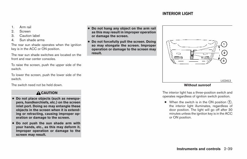
1. Arm rail2. Screen3. Caution label4. Sun shade armsThe rear sun shade operates when the ignitionkey is in the ACC or ON position.
The rear sun shade switches are located on thefront and rear center consoles.
To raise the screen, push the upper side of theswitch.
To lower the screen, push the lower side of theswitch.
The switch need not be held down.
CAUTION
● Do not place objects (such as newspa-pers, handkerchiefs, etc.) on the screeninlet port. Doing so may entangle theseobjects in the screen when it is extend-ing or retracting, causing improper op-eration or damage to the screen.
● Do not push the sun shade arm withyour hands, etc., as this may deform it.Improper operation or damage to thescreen may result.
● Do not hang any object on the arm railas this may result in improper operationor damage the screen.
● Do not forcefully pull the screen. Doingso may elongate the screen. Improperoperation or damage to the screen mayresult.
The interior light has a three-position switch andoperates regardless of ignition switch position.
● When the switch is in the ON position s1 ,the interior light illuminates, regardless ofdoor position. The light will go off after 30minutes unless the ignition key is in the ACCor ON position.
Without sunroofLIC0413
INTERIOR LIGHT
Instruments and controls 2-39
Z REVIEW COPY:—2004 Maxima (max)Owners Manual (owners)—USA English (nna)10/07/03—tbrooks X
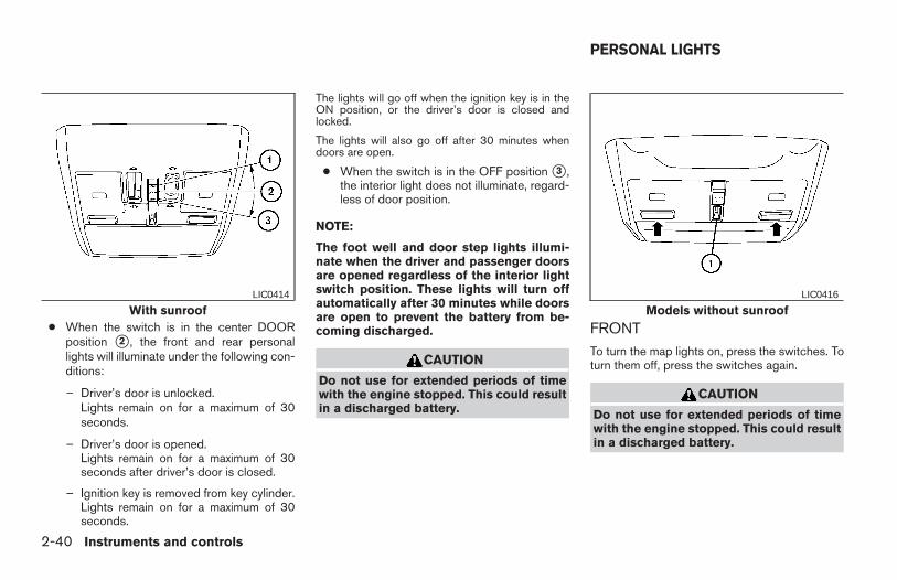
● When the switch is in the center DOORposition s2 , the front and rear personallights will illuminate under the following con-ditions:
– Driver’s door is unlocked.Lights remain on for a maximum of 30seconds.
– Driver’s door is opened.Lights remain on for a maximum of 30seconds after driver’s door is closed.
– Ignition key is removed from key cylinder.Lights remain on for a maximum of 30seconds.
The lights will go off when the ignition key is in theON position, or the driver’s door is closed andlocked.
The lights will also go off after 30 minutes whendoors are open.
● When the switch is in the OFF position s3 ,the interior light does not illuminate, regard-less of door position.
NOTE:
The foot well and door step lights illumi-nate when the driver and passenger doorsare opened regardless of the interior lightswitch position. These lights will turn offautomatically after 30 minutes while doorsare open to prevent the battery from be-coming discharged.
CAUTION
Do not use for extended periods of timewith the engine stopped. This could resultin a discharged battery.
FRONTTo turn the map lights on, press the switches. Toturn them off, press the switches again.
CAUTION
Do not use for extended periods of timewith the engine stopped. This could resultin a discharged battery.
With sunroofLIC0414
Models without sunroofLIC0416
PERSONAL LIGHTS
2-40 Instruments and controls
Z REVIEW COPY:—2004 Maxima (max)Owners Manual (owners)—USA English (nna)10/07/03—tbrooks X
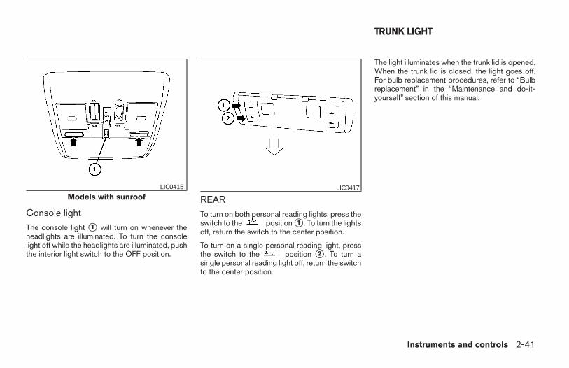
Console lightThe console light s1 will turn on whenever theheadlights are illuminated. To turn the consolelight off while the headlights are illuminated, pushthe interior light switch to the OFF position.
REARTo turn on both personal reading lights, press theswitch to the position s1 . To turn the lightsoff, return the switch to the center position.
To turn on a single personal reading light, pressthe switch to the position s2 . To turn asingle personal reading light off, return the switchto the center position.
The light illuminates when the trunk lid is opened.When the trunk lid is closed, the light goes off.For bulb replacement procedures, refer to “Bulbreplacement” in the “Maintenance and do-it-yourself” section of this manual.
Models with sunroofLIC0415 LIC0417
TRUNK LIGHT
Instruments and controls 2-41
Z REVIEW COPY:—2004 Maxima (max)Owners Manual (owners)—USA English (nna)10/07/03—tbrooks X
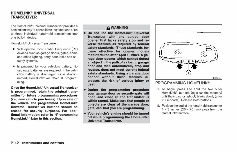
The HomeLinkT Universal Transceiver provides aconvenient way to consolidate the functions of upto three individual hand-held transmitters intoone built-in device.
HomeLinkT Universal Transceiver:
● Will operate most Radio Frequency (RF)devices such as garage doors, gates, homeand office lighting, entry door locks and se-curity systems.
● Is powered by your vehicle’s battery. Noseparate batteries are required. If the vehi-cle’s battery is discharged or is discon-nected, HomeLinkT will retain all program-ming.
Once the HomeLinkT Universal Transceiveris programmed, retain the original trans-mitter for future programming procedures(i.e., new vehicle purchases). Upon sale ofthe vehicle, the programmed HomeLinkTUniversal Transceiver buttons should beerased for security purposes. For addi-tional information refer to “ProgrammingHomeLinkT” later in this section.
WARNING
● Do not use the HomeLinkT UniversalTransceiver with any garage dooropener that lacks safety stop and re-verse features as required by federalsafety standards. (These standards be-came effective for opener modelsmanufactured after April 1, 1982). A ga-rage door opener which cannot detectan object in the path of a closing garagedoor and then automatically stop andreverse, does not meet current federalsafety standards. Using a garage dooropener without these features in-creases the risk of serious injury ordeath.
● During the programming procedureyour garage door or security gate willopen and close (if the transmitter iswithin range). Make sure that people orobjects are clear of the garage door,gate, etc. that you are programming.
● Your vehicle’s engine should be turnedoff while programming the HomeLinkTUniversal Transceiver.
PROGRAMMING HOMELINKT
1. To begin, press and hold the two outerHomeLinkT buttons (to clear the memory)until the indicator light s1 blinks slowly (after20 seconds). Release both buttons.
2. Position the end of the hand-held transmitter1 - 3 inches (26 - 76 mm) away from theHomeLinkT surface.
LIC0419
HOMELINKT UNIVERSALTRANSCEIVER
2-42 Instruments and controls
Z REVIEW COPY:—2004 Maxima (max)Owners Manual (owners)—USA English (nna)10/07/03—tbrooks X
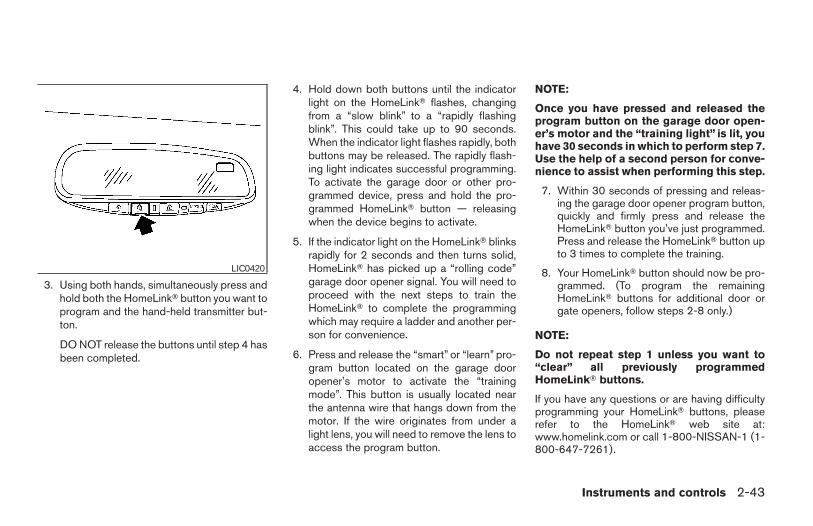
3. Using both hands, simultaneously press andhold both the HomeLinkT button you want toprogram and the hand-held transmitter but-ton.
DO NOT release the buttons until step 4 hasbeen completed.
4. Hold down both buttons until the indicatorlight on the HomeLinkT flashes, changingfrom a “slow blink” to a “rapidly flashingblink”. This could take up to 90 seconds.When the indicator light flashes rapidly, bothbuttons may be released. The rapidly flash-ing light indicates successful programming.To activate the garage door or other pro-grammed device, press and hold the pro-grammed HomeLinkT button — releasingwhen the device begins to activate.
5. If the indicator light on the HomeLinkT blinksrapidly for 2 seconds and then turns solid,HomeLinkT has picked up a “rolling code”garage door opener signal. You will need toproceed with the next steps to train theHomeLinkT to complete the programmingwhich may require a ladder and another per-son for convenience.
6. Press and release the “smart” or “learn” pro-gram button located on the garage dooropener’s motor to activate the “trainingmode”. This button is usually located nearthe antenna wire that hangs down from themotor. If the wire originates from under alight lens, you will need to remove the lens toaccess the program button.
NOTE:
Once you have pressed and released theprogram button on the garage door open-er’s motor and the “training light” is lit, youhave 30 seconds in which to perform step 7.Use the help of a second person for conve-nience to assist when performing this step.
7. Within 30 seconds of pressing and releas-ing the garage door opener program button,quickly and firmly press and release theHomeLinkT button you’ve just programmed.Press and release the HomeLinkT button upto 3 times to complete the training.
8. Your HomeLinkT button should now be pro-grammed. (To program the remainingHomeLinkT buttons for additional door orgate openers, follow steps 2-8 only.)
NOTE:
Do not repeat step 1 unless you want to“clear” all previously programmedHomeLinkT buttons.
If you have any questions or are having difficultyprogramming your HomeLinkT buttons, pleaserefer to the HomeLinkT web site at:www.homelink.com or call 1-800-NISSAN-1 (1-800-647-7261).
LIC0420
Instruments and controls 2-43
Z REVIEW COPY:—2004 Maxima (max)Owners Manual (owners)—USA English (nna)10/07/03—tbrooks X
PROGRAMMING HOMELINKT FORCANADIAN CUSTOMERSPrior to 1992, D.O.C. regulations required hand-held transmitters to stop transmitting after 2 sec-onds. To program your hand-held transmitter toHomeLinkT, continue to press and hold theHomeLinkT button (note steps 2 - 4 under “Pro-gramming HomeLinkT”) while you press and re-press (“cycle”) your hand-held transmitters every2 seconds until the indicator light flashes rapidly(indicating successful programming).
NOTE:
When programming a garage door opener,etc., it is advised to unplug the device dur-ing the “cycling” process to prevent pos-sible damage to the garage door openercomponents.
OPERATING THE HOMELINKTUNIVERSAL TRANSCEIVERThe HomeLinkT Universal Transceiver (once pro-grammed) may now be used to activate the ga-rage door, etc. To operate, simply press the ap-propriate programmed HomeLinkT UniversalTransceiver button. The red indicator light willilluminate while the signal is being transmitted.
PROGRAMMING TROUBLE-DIAGNOSISIf the HomeLinkT does not quickly learn the hand-held transmitter information:
● replace the hand-held transmitter batterieswith new batteries.
● position the hand-held transmitter with itsbattery area facing away from theHomeLinkT surface.
● press and hold both the HomeLinkT andhand-held transmitter buttons without inter-ruption.
● position the hand-held transmitter 1 - 3inches (26 - 76 mm) away from theHomeLinkT surface. Hold the transmitter inthat position for up to 15 seconds. IfHomeLinkT is not programmed within thattime, try holding the transmitter in anotherposition – keeping the indicator light in viewat all times.
If you continue to have programming difficulties,please contact the NISSAN Consumer AffairsDepartment. The phone numbers are located inthe Foreword of this manual.
CLEARING THE PROGRAMMEDINFORMATIONIndividual buttons cannot be cleared. However,to clear all programming, press and hold the twooutside buttons and release when the indicatorlight begins to flash (approximately 20 seconds).
REPROGRAMMING A SINGLEHOMELINKT BUTTONTo reprogram a HomeLinkT Universal Transceiverbutton, complete the following.
1. Press and hold the desired HomeLinkT but-ton. Do not release the button until step 4has been completed.
2. When the indicator light begins to flashslowly (after 20 seconds), position thehand-held transmitter 1 - 3 inches (26 - 76mm) away from the HomeLinkT surface.
3. Press and hold the hand-held transmitterbutton.
4. The HomeLinkT indicator light will flash, firstslowly and then rapidly. When the indicatorlight begins to flash rapidly, release bothbuttons.
2-44 Instruments and controls
Z REVIEW COPY:—2004 Maxima (max)Owners Manual (owners)—USA English (nna)10/07/03—tbrooks X
The HomeLinkT Universal Transceiver button hasnow been reprogrammed. The new device canbe activated by pushing the HomeLinkT buttonthat was just programmed. This procedure willnot affect any other programmed HomeLinkTbuttons.
IF YOUR VEHICLE IS STOLENIf your vehicle is stolen, you should change thecodes of any non-rolling code device that hasbeen programmed into HomeLinkT. Consult theOwner’s Manual of each device or call the manu-facturer or dealer of those devices for additionalinformation.
When your vehicle is recovered, you willneed to reprogram the HomeLinkT Univer-sal Transceiver with your new transmitterinformation.
FCC Notice:
This device complies with FCC rules part15. Operation is subject to the followingtwo conditions: (1) This device may notcause harmful interference and (2) This de-vice must accept any interference that maybe received, including interference thatmay cause undesired operation.
This transmitter has been tested and com-plies with FCC and DOC/MDC rules.Changes or modifications not expressly ap-
proved by the party responsible for compli-ance could void the user’s authority to op-erate the device.
DOC: ISTC 1763K1313
FCC I.D. CV2V67690
Instruments and controls 2-45
Z REVIEW COPY:—2004 Maxima (max)Owners Manual (owners)—USA English (nna)10/07/03—tbrooks X

2-46 Instruments and controls
MEMO
3 Pre-driving checks and adjustments
Keys . . . . . . . . . . . . . . . . . . . . . . . . . . . . . . . . . . . . . . . . . . . . . 3-2Nissan vehicle immobilizer system (NVIS)keys . . . . . . . . . . . . . . . . . . . . . . . . . . . . . . . . . . . . . . . . . . 3-2
Doors . . . . . . . . . . . . . . . . . . . . . . . . . . . . . . . . . . . . . . . . . . . . 3-3Locking with key. . . . . . . . . . . . . . . . . . . . . . . . . . . . . . . . 3-3Locking with inside lock knob . . . . . . . . . . . . . . . . . . . . 3-4Locking with power door lock switch . . . . . . . . . . . . . 3-4Child safety rear door lock . . . . . . . . . . . . . . . . . . . . . . . 3-5
Remote keyless entry system . . . . . . . . . . . . . . . . . . . . . . . 3-5How to use remote keyless entry system . . . . . . . . . . 3-6Battery replacement . . . . . . . . . . . . . . . . . . . . . . . . . . . . 3-9
Hood . . . . . . . . . . . . . . . . . . . . . . . . . . . . . . . . . . . . . . . . . . .3-10Trunk lid . . . . . . . . . . . . . . . . . . . . . . . . . . . . . . . . . . . . . . . . .3-10
Opener operation. . . . . . . . . . . . . . . . . . . . . . . . . . . . . .3-10Secondary trunk lid release . . . . . . . . . . . . . . . . . . . . . 3-11Interior trunk lid release . . . . . . . . . . . . . . . . . . . . . . . . 3-12
Fuel filler lid . . . . . . . . . . . . . . . . . . . . . . . . . . . . . . . . . . . . . .3-13Opener operation. . . . . . . . . . . . . . . . . . . . . . . . . . . . . .3-13Fuel filler cap. . . . . . . . . . . . . . . . . . . . . . . . . . . . . . . . . .3-13
Tilting telescopic steering column . . . . . . . . . . . . . . . . . . 3-14Automatic operation (if so equipped). . . . . . . . . . . . . 3-14Manual operation . . . . . . . . . . . . . . . . . . . . . . . . . . . . . .3-15
Sun visors . . . . . . . . . . . . . . . . . . . . . . . . . . . . . . . . . . . . . . .3-16Vanity mirrors . . . . . . . . . . . . . . . . . . . . . . . . . . . . . . . . .3-16
Mirrors . . . . . . . . . . . . . . . . . . . . . . . . . . . . . . . . . . . . . . . . . .3-17Automatic anti-glare inside mirror. . . . . . . . . . . . . . . . 3-17Outside mirrors . . . . . . . . . . . . . . . . . . . . . . . . . . . . . . .3-17
Automatic drive positioner (if so equipped) . . . . . . . . . . 3-19Memory storage function . . . . . . . . . . . . . . . . . . . . . . . 3-19Entry/exit function (for automatictransmission model) . . . . . . . . . . . . . . . . . . . . . . . . . . . 3-20System operation. . . . . . . . . . . . . . . . . . . . . . . . . . . . . .3-21
Z REVIEW COPY:—2004 Maxima (max)Owners Manual (owners)—USA English (nna)10/20/03—arosenma X
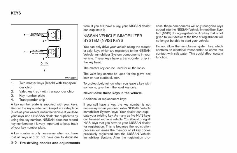
1. Two master keys (black) with transpon-der chip
2. Valet key (red) with transponder chip3. Key number plate4. Transponder chipA key number plate is supplied with your keys.Record the key number and keep it in a safe place(such as your wallet), not in the vehicle. If you loseyour keys, see a NISSAN dealer for duplicates byusing the key number. NISSAN does not recordkey numbers so it is very important to keep trackof your key number plate.
A key number is only necessary when you havelost all keys and do not have one to duplicate
from. If you still have a key, your NISSAN dealercan duplicate it.
NISSAN VEHICLE IMMOBILIZERSYSTEM (NVIS) KEYS
You can only drive your vehicle using the masteror valet keys which are registered to the NISSANVehicle Immobilizer System components in yourvehicle. These keys have a transponder chip inthe key head.
The master key can be used for all the locks.
The valet key cannot be used for the glove boxlock or rear seatback lock.
To protect belongings when you leave a key withsomeone, give them the valet key only.
Never leave these keys in the vehicle.
Additional or replacement keys:
If you still have a key, the key number is notnecessary when you need extra NISSAN VehicleImmobilizer System keys. Your dealer can dupli-cate your existing key. As many as five NVIS keyscan be used with one vehicle. You should bring allNVIS keys that you have to your NISSAN dealerfor registration. This is because the registrationprocess will erase the memory of all key codespreviously registered into the NISSAN VehicleImmobilizer System. After the registration pro-
cess, these components will only recognize keyscoded into the NISSAN Vehicle Immobilizer Sys-tem (NVIS) during registration. Any key that is notgiven to your dealer at the time of registration willno longer be able to start your vehicle.
Do not allow the immobilizer system key, whichcontains an electrical transponder, to come intocontact with salt water. This could affect systemfunction.
WPD0128
KEYS
3-2 Pre-driving checks and adjustments
Z REVIEW COPY:—2004 Maxima (max)Owners Manual (owners)—USA English (nna)10/07/03—tbrooks X
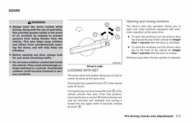
WARNING
● Always have the doors locked whiledriving. Along with the use of seat belts,this provides greater safety in the eventof an accident by helping to preventpersons from being thrown from thevehicle. This also helps keep childrenand others from unintentionally open-ing the doors, and will help keep outintruders.
● Before opening any door, always lookfor and avoid oncoming traffic.
● Do not leave children unattended insidethe vehicle. They could unknowingly ac-tivate switches or controls. Unattendedchildren could become involved in seri-ous accidents.
LOCKING WITH KEY
The power door lock system allows you to lock orunlock all doors at the same time.
Turning the key toward the front s1 of the vehiclelocks all doors.
Turning the key one time toward the rear s2 of thevehicle unlocks that door. From that position,returning the key to neutral s3 (where the key canonly be removed and inserted) and turning ittoward the rear again within 5 seconds unlocksall doors s4 .
Opening and closing windowsThe driver’s door key operation allows you toopen and close windows equipped with auto-matic operation at the same time.
● To open the windows, turn the driver’s doorkey toward the rear of the vehicle for longerthan 1 second after the door is unlocked.
● To close the windows, turn the driver’s doorkey to the front of the vehicle for longerthan 1 second after the door is locked.
Windows stop when the key cylinder is released.
Driver’s sideLPD0181
DOORS
Pre-driving checks and adjustments 3-3
Z REVIEW COPY:—2004 Maxima (max)Owners Manual (owners)—USA English (nna)10/07/03—tbrooks X
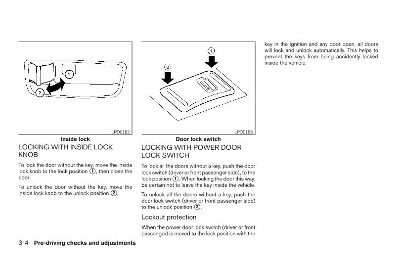
LOCKING WITH INSIDE LOCKKNOBTo lock the door without the key, move the insidelock knob to the lock position s1 , then close thedoor.
To unlock the door without the key, move theinside lock knob to the unlock position s2 .
LOCKING WITH POWER DOORLOCK SWITCH
To lock all the doors without a key, push the doorlock switch (driver or front passenger side), to thelock position s1 . When locking the door this way,be certain not to leave the key inside the vehicle.
To unlock all the doors without a key, push thedoor lock switch (driver or front passenger side)to the unlock position s2 .
Lockout protectionWhen the power door lock switch (driver or frontpassenger) is moved to the lock position with the
key in the ignition and any door open, all doorswill lock and unlock automatically. This helps toprevent the keys from being accidently lockedinside the vehicle.
Inside lockLPD0182
Door lock switchLPD0183
3-4 Pre-driving checks and adjustments
Z REVIEW COPY:—2004 Maxima (max)Owners Manual (owners)—USA English (nna)10/07/03—tbrooks X
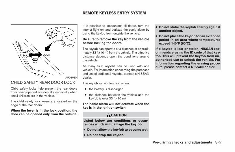
CHILD SAFETY REAR DOOR LOCKChild safety locks help prevent the rear doorsfrom being opened accidentally, especially whensmall children are in the vehicle.
The child safety lock levers are located on theedge of the rear doors.
When the lever is in the lock position, thedoor can be opened only from the outside.
It is possible to lock/unlock all doors, turn theinterior light on, and activate the panic alarm byusing the keyfob from outside the vehicle.
Be sure to remove the key from the vehiclebefore locking the doors.
The keyfob can operate at a distance of approxi-mately 33 ft (10 m) from the vehicle. The effectivedistance depends upon the conditions aroundthe vehicle.
As many as 5 keyfobs can be used with onevehicle. For information concerning the purchaseand use of additional keyfobs, contact a NISSANdealer.
The keyfob will not function when:
● the battery is discharged
● the distance between the vehicle and thekeyfob is over 33 ft (10 m)
The panic alarm will not activate when thekey is in the ignition switch.
CAUTION
Listed below are conditions or occur-rences which will damage the keyfob:
● Do not allow the keyfob to become wet.
● Do not drop the keyfob.
● Do not strike the keyfob sharply againstanother object.
● Do not place the keyfob for an extendedperiod in an area where temperaturesexceed 140°F (60°C).
If a keyfob is lost or stolen, NISSAN rec-ommends erasing the ID code of that key-fob. This will prevent the keyfob from un-authorized use to unlock the vehicle. Forinformation regarding the erasing proce-dure, please contact a NISSAN dealer.
APD1010
REMOTE KEYLESS ENTRY SYSTEM
Pre-driving checks and adjustments 3-5
Z REVIEW COPY:—2004 Maxima (max)Owners Manual (owners)—USA English (nna)10/07/03—tbrooks X
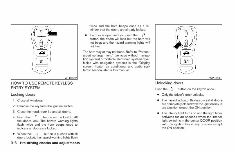
HOW TO USE REMOTE KEYLESSENTRY SYSTEM
Locking doors1. Close all windows
2. Remove the key from the ignition switch.
3. Close the hood, trunk lid and all doors.
4. Push the button on the keyfob. Allthe doors lock. The hazard warning lightsflash twice and the horn beeps once toindicate all doors are locked.
● When the button is pushed with alldoors locked, the hazard warning lights flash
twice and the horn beeps once as a re-minder that the doors are already locked.
● If a door is open and you push thebutton, the doors will lock but the horn willnot beep and the hazard warning lights willnot flash.
The horn may or may not beep. Refer to “Person-alized settings menu” (vehicles without naviga-tion system) or “Vehicle electronic systems” (ve-hicles with navigation system) in the “Displayscreen, heater, air conditioner and audio sys-tems” section later in this manual.
Unlocking doorsPush the button on the keyfob once.
● Only the driver’s door unlocks.
● The hazard indicator flashes once if all doorsare completely closed with the ignition key inany position except the ON position.
● The interior light turns on and the light timeractivates for 30 seconds when the interiorlight switch is in the center DOOR positionwith the ignition key in any position exceptthe ON position.
WPD0132 WPD0133
3-6 Pre-driving checks and adjustments
Z REVIEW COPY:—2004 Maxima (max)Owners Manual (owners)—USA English (nna)10/07/03—tbrooks X
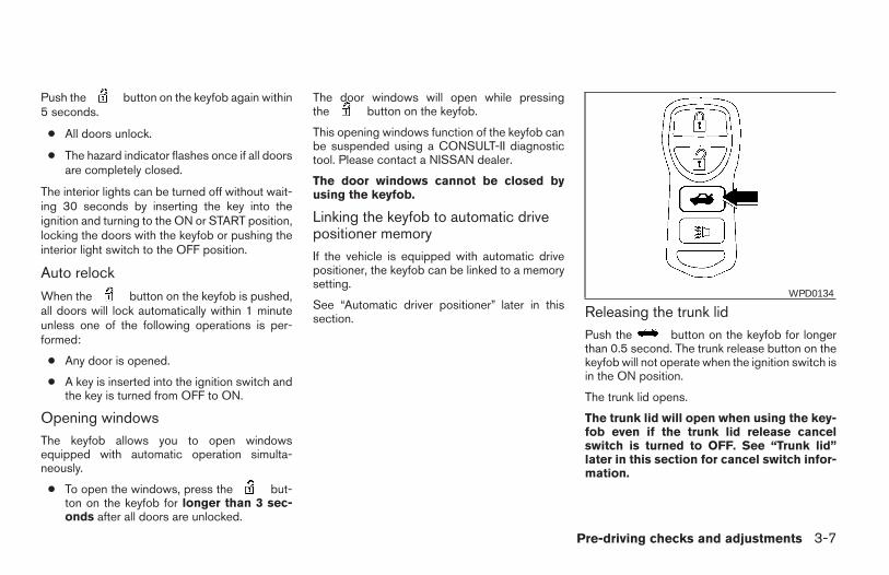
Push the button on the keyfob again within5 seconds.
● All doors unlock.
● The hazard indicator flashes once if all doorsare completely closed.
The interior lights can be turned off without wait-ing 30 seconds by inserting the key into theignition and turning to the ON or START position,locking the doors with the keyfob or pushing theinterior light switch to the OFF position.
Auto relock
When the button on the keyfob is pushed,all doors will lock automatically within 1 minuteunless one of the following operations is per-formed:
● Any door is opened.
● A key is inserted into the ignition switch andthe key is turned from OFF to ON.
Opening windowsThe keyfob allows you to open windowsequipped with automatic operation simulta-neously.
● To open the windows, press the but-ton on the keyfob for longer than 3 sec-onds after all doors are unlocked.
The door windows will open while pressingthe button on the keyfob.
This opening windows function of the keyfob canbe suspended using a CONSULT-II diagnostictool. Please contact a NISSAN dealer.
The door windows cannot be closed byusing the keyfob.
Linking the keyfob to automatic drivepositioner memoryIf the vehicle is equipped with automatic drivepositioner, the keyfob can be linked to a memorysetting.
See “Automatic driver positioner” later in thissection. Releasing the trunk lid
Push the button on the keyfob for longerthan 0.5 second. The trunk release button on thekeyfob will not operate when the ignition switch isin the ON position.
The trunk lid opens.
The trunk lid will open when using the key-fob even if the trunk lid release cancelswitch is turned to OFF. See “Trunk lid”later in this section for cancel switch infor-mation.
WPD0134
Pre-driving checks and adjustments 3-7
Z REVIEW COPY:—2004 Maxima (max)Owners Manual (owners)—USA English (nna)10/07/03—tbrooks X
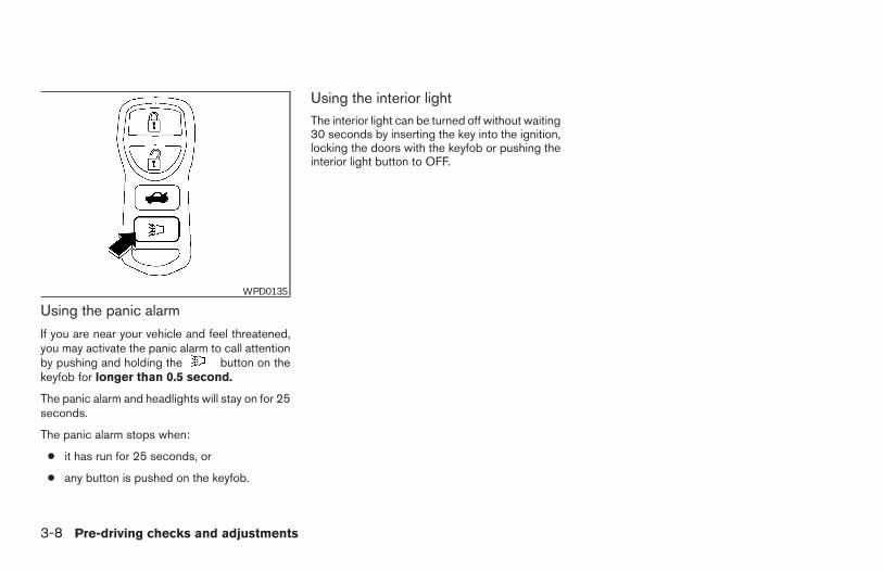
Using the panic alarm
If you are near your vehicle and feel threatened,you may activate the panic alarm to call attentionby pushing and holding the button on thekeyfob for longer than 0.5 second.
The panic alarm and headlights will stay on for 25seconds.
The panic alarm stops when:
● it has run for 25 seconds, or
● any button is pushed on the keyfob.
Using the interior lightThe interior light can be turned off without waiting30 seconds by inserting the key into the ignition,locking the doors with the keyfob or pushing theinterior light button to OFF.
WPD0135
3-8 Pre-driving checks and adjustments
Z REVIEW COPY:—2004 Maxima (max)Owners Manual (owners)—USA English (nna)10/07/03—tbrooks X
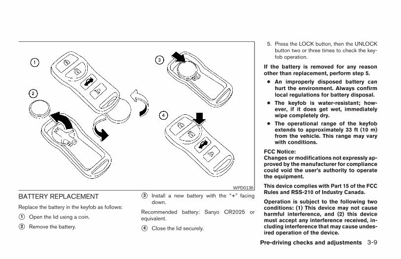
BATTERY REPLACEMENT
Replace the battery in the keyfob as follows:
s1 Open the lid using a coin.
s2 Remove the battery.
s3 Install a new battery with the “+” facingdown.
Recommended battery: Sanyo CR2025 orequivalent.
s4 Close the lid securely.
5. Press the LOCK button, then the UNLOCKbutton two or three times to check the key-fob operation.
If the battery is removed for any reasonother than replacement, perform step 5.
● An improperly disposed battery canhurt the environment. Always confirmlocal regulations for battery disposal.
● The keyfob is water-resistant; how-ever, if it does get wet, immediatelywipe completely dry.
● The operational range of the keyfobextends to approximately 33 ft (10 m)from the vehicle. This range may varywith conditions.
FCC Notice:Changes or modifications not expressly ap-proved by the manufacturer for compliancecould void the user’s authority to operatethe equipment.
This device complies with Part 15 of the FCCRules and RSS-210 of Industry Canada.
Operation is subject to the following twoconditions: (1) This device may not causeharmful interference, and (2) this devicemust accept any interference received, in-cluding interference that may cause undes-ired operation of the device.
WPD0136
Pre-driving checks and adjustments 3-9
Z REVIEW COPY:—2004 Maxima (max)Owners Manual (owners)—USA English (nna)10/07/03—tbrooks X
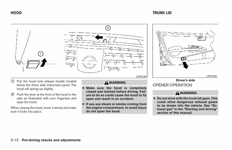
s1 Pull the hood lock release handle locatedbelow the driver side instrument panel. Thehood will spring up slightly.
s2 Push the lever at the front of the hood to theside as illustrated with your fingertips andraise the hood.
When closing the hood, lower it slowly and makesure it locks into place.
WARNING
● Make sure the hood is completelyclosed and latched before driving. Fail-ure to do so could cause the hood to flyopen and result in an accident.
● If you see steam or smoke coming fromthe engine compartment, to avoid injurydo not open the hood.
OPENER OPERATION
WARNING
● Do not drive with the trunk lid open. Thiscould allow dangerous exhaust gasesto be drawn into the vehicle. See “Ex-haust gas” in the “Starting and driving”section of this manual.
LPD0184Driver’s side
LPD0185
HOOD TRUNK LID
3-10 Pre-driving checks and adjustments
Z REVIEW COPY:—2004 Maxima (max)Owners Manual (owners)—USA English (nna)10/07/03—tbrooks X
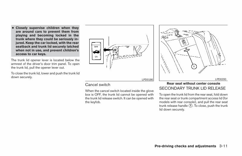
● Closely supervise children when theyare around cars to prevent them fromplaying and becoming locked in thetrunk where they could be seriously in-jured. Keep the car locked, with the rearseatback and trunk lid securely latchedwhen not in use, and prevent children’saccess to car keys.
The trunk lid opener lever is located below thearmrest of the driver’s door trim panel. To openthe trunk lid, pull the opener lever out.
To close the trunk lid, lower and push the trunk liddown securely.
Cancel switchWhen the cancel switch located inside the glovebox is OFF, the trunk lid cannot be opened withthe trunk lid release switch. It can be opened withthe keyfob.
SECONDARY TRUNK LID RELEASETo open the trunk lid from the rear seat, fold downthe rear seat or trunk compartment access lid (formodels with rear console), and pull the rear seattrunk release handle s1 . To close, push the trunklid down securely.
LPD0186Rear seat without center console
LPD0200
Pre-driving checks and adjustments 3-11
Z REVIEW COPY:—2004 Maxima (max)Owners Manual (owners)—USA English (nna)10/20/03—arosenma X
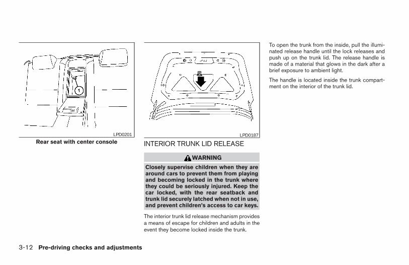
INTERIOR TRUNK LID RELEASE
WARNING
Closely supervise children when they arearound cars to prevent them from playingand becoming locked in the trunk wherethey could be seriously injured. Keep thecar locked, with the rear seatback andtrunk lid securely latched when not in use,and prevent children’s access to car keys.
The interior trunk lid release mechanism providesa means of escape for children and adults in theevent they become locked inside the trunk.
To open the trunk from the inside, pull the illumi-nated release handle until the lock releases andpush up on the trunk lid. The release handle ismade of a material that glows in the dark after abrief exposure to ambient light.
The handle is located inside the trunk compart-ment on the interior of the trunk lid.
Rear seat with center consoleLPD0201 LPD0187
3-12 Pre-driving checks and adjustments
Z REVIEW COPY:—2004 Maxima (max)Owners Manual (owners)—USA English (nna)10/20/03—arosenma X
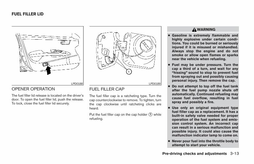
OPENER OPERATIONThe fuel filler lid release is located on the driver’sdoor. To open the fuel filler lid, push the release.To lock, close the fuel filler lid securely.
FUEL FILLER CAP
The fuel filler cap is a ratcheting type. Turn thecap counterclockwise to remove. To tighten, turnthe cap clockwise until ratcheting clicks areheard.
Put the fuel filler cap on the cap holder s1 whilerefueling.
WARNING
● Gasoline is extremely flammable andhighly explosive under certain condi-tions. You could be burned or seriouslyinjured if it is misused or mishandled.Always stop the engine and do notsmoke or allow open flames or sparksnear the vehicle when refueling.
● Fuel may be under pressure. Turn thecap a third of a turn, and wait for any“hissing” sound to stop to prevent fuelfrom spraying out and possibly causingpersonal injury. Then remove the cap.
● Do not attempt to top off the fuel tankafter the fuel pump nozzle shuts offautomatically. Continued refueling maycause fuel overflow, resulting in fuelspray and possibly a fire.
● Use only an original equipment typefuel filler cap as a replacement. It has abuilt-in safety valve needed for properoperation of the fuel system and emis-sion control system. An incorrect capcan result in a serious malfunction andpossible injury. It could also cause themalfunction indicator lamp to come on.
● Never pour fuel into the throttle body toattempt to start your vehicle.
LPD0188 LPD0189
FUEL FILLER LID
Pre-driving checks and adjustments 3-13
Z REVIEW COPY:—2004 Maxima (max)Owners Manual (owners)—USA English (nna)10/20/03—arosenma X
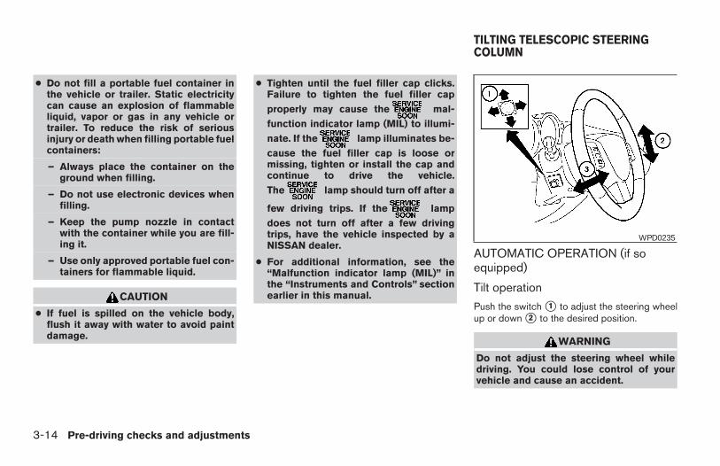
● Do not fill a portable fuel container inthe vehicle or trailer. Static electricitycan cause an explosion of flammableliquid, vapor or gas in any vehicle ortrailer. To reduce the risk of seriousinjury or death when filling portable fuelcontainers:
– Always place the container on theground when filling.
– Do not use electronic devices whenfilling.
– Keep the pump nozzle in contactwith the container while you are fill-ing it.
– Use only approved portable fuel con-tainers for flammable liquid.
CAUTION
● If fuel is spilled on the vehicle body,flush it away with water to avoid paintdamage.
● Tighten until the fuel filler cap clicks.Failure to tighten the fuel filler cap
properly may cause the mal-
function indicator lamp (MIL) to illumi-
nate. If the lamp illuminates be-
cause the fuel filler cap is loose ormissing, tighten or install the cap andcontinue to drive the vehicle.
The lamp should turn off after a
few driving trips. If the lamp
does not turn off after a few drivingtrips, have the vehicle inspected by aNISSAN dealer.
● For additional information, see the“Malfunction indicator lamp (MIL)” inthe “Instruments and Controls” sectionearlier in this manual.
AUTOMATIC OPERATION (if soequipped)
Tilt operation
Push the switch s1 to adjust the steering wheelup or down s2 to the desired position.
WARNING
Do not adjust the steering wheel whiledriving. You could lose control of yourvehicle and cause an accident.
WPD0235
TILTING TELESCOPIC STEERINGCOLUMN
3-14 Pre-driving checks and adjustments
Z REVIEW COPY:—2004 Maxima (max)Owners Manual (owners)—USA English (nna)10/20/03—arosenma X
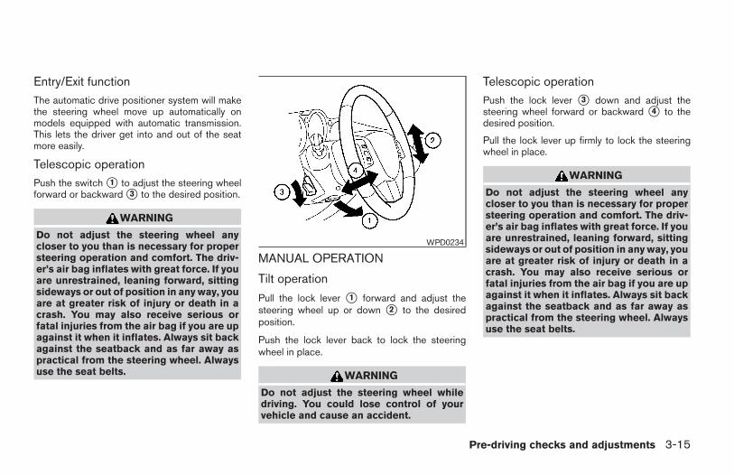
Entry/Exit functionThe automatic drive positioner system will makethe steering wheel move up automatically onmodels equipped with automatic transmission.This lets the driver get into and out of the seatmore easily.
Telescopic operationPush the switch s1 to adjust the steering wheelforward or backward s3 to the desired position.
WARNING
Do not adjust the steering wheel anycloser to you than is necessary for propersteering operation and comfort. The driv-er’s air bag inflates with great force. If youare unrestrained, leaning forward, sittingsideways or out of position in any way, youare at greater risk of injury or death in acrash. You may also receive serious orfatal injuries from the air bag if you are upagainst it when it inflates. Always sit backagainst the seatback and as far away aspractical from the steering wheel. Alwaysuse the seat belts.
MANUAL OPERATION
Tilt operation
Pull the lock lever s1 forward and adjust thesteering wheel up or down s2 to the desiredposition.
Push the lock lever back to lock the steeringwheel in place.
WARNING
Do not adjust the steering wheel whiledriving. You could lose control of yourvehicle and cause an accident.
Telescopic operationPush the lock lever s3 down and adjust thesteering wheel forward or backward s4 to thedesired position.
Pull the lock lever up firmly to lock the steeringwheel in place.
WARNING
Do not adjust the steering wheel anycloser to you than is necessary for propersteering operation and comfort. The driv-er’s air bag inflates with great force. If youare unrestrained, leaning forward, sittingsideways or out of position in any way, youare at greater risk of injury or death in acrash. You may also receive serious orfatal injuries from the air bag if you are upagainst it when it inflates. Always sit backagainst the seatback and as far away aspractical from the steering wheel. Alwaysuse the seat belts.
WPD0234
Pre-driving checks and adjustments 3-15
Z REVIEW COPY:—2004 Maxima (max)Owners Manual (owners)—USA English (nna)10/20/03—arosenma X
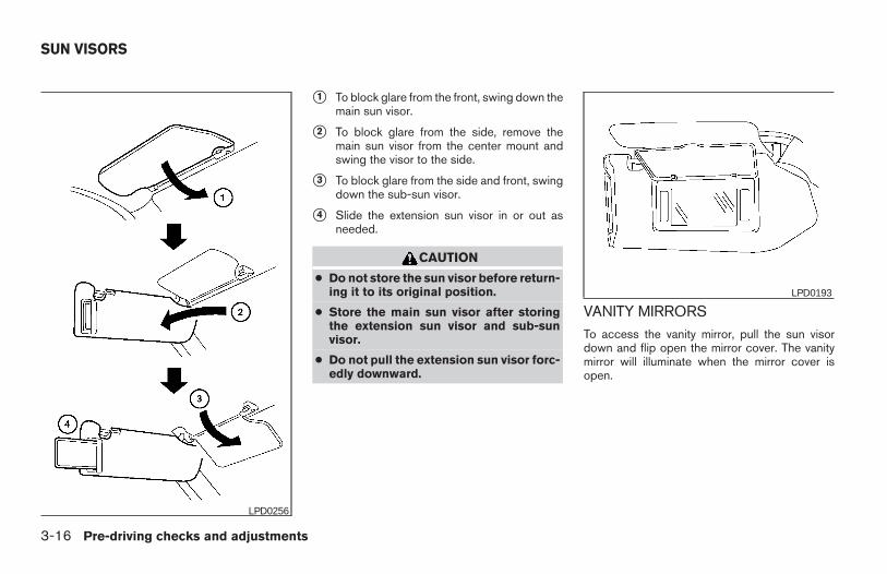
s1 To block glare from the front, swing down themain sun visor.
s2 To block glare from the side, remove themain sun visor from the center mount andswing the visor to the side.
s3 To block glare from the side and front, swingdown the sub-sun visor.
s4 Slide the extension sun visor in or out asneeded.
CAUTION
● Do not store the sun visor before return-ing it to its original position.
● Store the main sun visor after storingthe extension sun visor and sub-sunvisor.
● Do not pull the extension sun visor forc-edly downward.
VANITY MIRRORSTo access the vanity mirror, pull the sun visordown and flip open the mirror cover. The vanitymirror will illuminate when the mirror cover isopen.
LPD0256
LPD0193
SUN VISORS
3-16 Pre-driving checks and adjustments
Z REVIEW COPY:—2004 Maxima (max)Owners Manual (owners)—USA English (nna)10/20/03—arosenma X
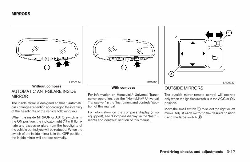
AUTOMATIC ANTI-GLARE INSIDEMIRROR
The inside mirror is designed so that it automati-cally changes reflection according to the intensityof the headlights of the vehicle following you.
When the inside MIRROR or AUTO switch is inthe ON position, the indicator light s1 will illumi-nate and excessive glare from the headlights ofthe vehicle behind you will be reduced. When theswitch of the inside mirror is in the OFF position,the inside mirror will operate normally.
For information on HomeLinkT Universal Trans-ceiver operation, see the “HomeLinkT UniversalTransceiver” in the “Instrument and controls” sec-tion of this manual.
For information on the compass display (if soequipped), see “Compass display” in the “Instru-ments and controls” section of this manual.
OUTSIDE MIRRORS
The outside mirror remote control will operateonly when the ignition switch is in the ACC or ONposition.
Move the small switch s1 to select the right or leftmirror. Adjust each mirror to the desired positionusing the large switch s2 .
Without compassLPD0194
With compass
LPD0195 LPD0237
MIRRORS
Pre-driving checks and adjustments 3-17
Z REVIEW COPY:—2004 Maxima (max)Owners Manual (owners)—USA English (nna)10/20/03—arosenma X
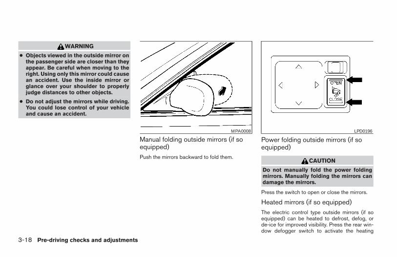
WARNING
● Objects viewed in the outside mirror onthe passenger side are closer than theyappear. Be careful when moving to theright. Using only this mirror could causean accident. Use the inside mirror orglance over your shoulder to properlyjudge distances to other objects.
● Do not adjust the mirrors while driving.You could lose control of your vehicleand cause an accident.
Manual folding outside mirrors (if soequipped)Push the mirrors backward to fold them.
Power folding outside mirrors (if soequipped)
CAUTION
Do not manually fold the power foldingmirrors. Manually folding the mirrors candamage the mirrors.
Press the switch to open or close the mirrors.
Heated mirrors (if so equipped)The electric control type outside mirrors (if soequipped) can be heated to defrost, defog, orde-ice for improved visibility. Press the rear win-dow defogger switch to activate the heating
MPA0008 LPD0196
3-18 Pre-driving checks and adjustments
Z REVIEW COPY:—2004 Maxima (max)Owners Manual (owners)—USA English (nna)10/20/03—arosenma X
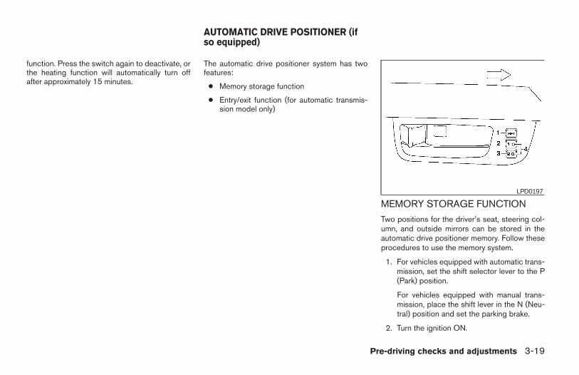
function. Press the switch again to deactivate, orthe heating function will automatically turn offafter approximately 15 minutes.
The automatic drive positioner system has twofeatures:
● Memory storage function
● Entry/exit function (for automatic transmis-sion model only)
MEMORY STORAGE FUNCTION
Two positions for the driver’s seat, steering col-umn, and outside mirrors can be stored in theautomatic drive positioner memory. Follow theseprocedures to use the memory system.
1. For vehicles equipped with automatic trans-mission, set the shift selector lever to the P(Park) position.
For vehicles equipped with manual trans-mission, place the shift lever in the N (Neu-tral) position and set the parking brake.
2. Turn the ignition ON.
LPD0197
AUTOMATIC DRIVE POSITIONER (ifso equipped)
Pre-driving checks and adjustments 3-19
Z REVIEW COPY:—2004 Maxima (max)Owners Manual (owners)—USA English (nna)10/20/03—arosenma X
3. Adjust the driver’s seat, steering column andoutside mirrors to the desired positions bymanually operating each adjusting switch.For additional information, see “Seats” in the“Safety—Seats, seat belts and supplemen-tal air bags” section and “Steering wheel”and “Outside mirrors” earlier in this section.
During this step, do not turn the ignition toany positions other than ON.
4. Push the SET switch and, within 5 seconds,push the memory switch (1 or 2) fully for atleast 1 second.
The indicator light for the pushed memoryswitch will come on and stay on for approxi-mately 5 seconds after pushing the switch.After the indicator light goes off, the se-lected positions are stored in the selectedmemory (1 or 2).
If memory is stored in the same memory switch,the previous memory will be deleted.
Linking a keyfob to a stored memoryposition
A keyfob can be linked to a stored memory posi-tion with the following procedure.
1. Follow the steps for storing a memory posi-tion.
2. While the indicator light for the memoryswitch being set is illuminated for 5 sec-onds, press the button on the keyfob.The indicator light will blink. After the indica-tor light goes off, the keyfob is linked to thatmemory setting.
With the key removed from the ignition switch,press the button on the keyfob. The driv-er’s seat and outside mirrors will move to thememorized position.
Confirming memory storage● Turn the ignition ON and push the SET
switch. If the main memory has not beenstored, the indicator light will come on forapproximately 0.5 seconds. When thememory has stored the position, the indica-tor light will stay on for approximately 5 sec-onds.
● If the battery cable is disconnected, or if thefuse blows, the memory will be canceled. Insuch a case, reset the desired positionsusing the following procedures.
1. Open and close the driver’s door more thantwo times with the ignition key in the LOCKposition.
2. Reset the desired position using the previ-ous procedure.
Selecting the memorized position
1. Set the automatic transmission selector le-ver to the P (Park) position.
2. Turn the ignition ON.
3. Push the memory switch (1 or 2) fully for atleast 1 second.
The driver’s seat, steering column and out-side mirrors will move to the memorized po-sition with the indicator light flashing, andthen the light will stay on for approximately 5seconds.
ENTRY/EXIT FUNCTION (forautomatic transmission model)This system is designed so that the driver’s seatand steering column will automatically movewhen the automatic transmission selector lever isin the P (Park) position. This allows the driver toget into and out of the driver’s seat more easily.(This feature is not available on manual transmis-sion model.)
The driver’s seat will slide backward and thesteering wheel will move up:
● When the key is removed from the ignitionswitch.
● When the driver’s door is opened with thekey turned to LOCK.
3-20 Pre-driving checks and adjustments
Z REVIEW COPY:—2004 Maxima (max)Owners Manual (owners)—USA English (nna)10/20/03—arosenma X
● When the key is turned from ACC to LOCKwith the driver’s door open while the auto-matic transmission selector lever is in the P(Park) position.
The driver’s seat and steering wheel will return tothe previous position:
● When the key is inserted into the ignitionswitch.
● When the driver’s door is closed with the keyturned to LOCK.
● When the key is turned from ACC to ONwhile the automatic transmission selectorlever is in the P (Park) position.
The entry/exit feature can be adjusted or can-celed. See “Vehicle electronic systems” in the“Display screen, heater, air conditioner and audiosystems” section of this manual.
SYSTEM OPERATIONThe automatic drive positioner system will notwork or will stop operating under the followingconditions:
● when the vehicle speed is above 4 MPH (7km/h).
● when any two or more of the memoryswitches are simultaneously pushed whilethe automatic drive positioner is operating.
● when the adjusting switch for the driver’sseat is turned on while the automatic drivepositioner is operating.
● when the memory switch (1 or 2) is notpushed for at least 1 second.
● when the seat has been already moved tothe memorized position.
● when no seat position is stored in thememory switch.
The automatic drive positioner system can beadjusted and canceled. See “Vehicle electronicsystems” in the “Display screen, heater, air con-ditioner and audio systems” section of thismanual.
Pre-driving checks and adjustments 3-21
Z REVIEW COPY:—2004 Maxima (max)Owners Manual (owners)—USA English (nna)10/20/03—arosenma X

3-22 Pre-driving checks and adjustments
MEMO
4 Display screen, heater, air conditionerand audio systems
Control panel buttons — without navigation system. . . . 4-2Names of components . . . . . . . . . . . . . . . . . . . . . . . . . . 4-3How to use JOYSTICK and “ENTER” button . . . . . . . 4-3How to use “PREV” button . . . . . . . . . . . . . . . . . . . . . . 4-3How to use “TRIP” button . . . . . . . . . . . . . . . . . . . . . . . 4-3How to use “FUEL ECON” button . . . . . . . . . . . . . . . . 4-4Clock . . . . . . . . . . . . . . . . . . . . . . . . . . . . . . . . . . . . . . . . . 4-4How to use “E/M” button . . . . . . . . . . . . . . . . . . . . . . . . 4-4How to use (maintenance) button . . . . . . . . . . 4-5How to use the “SETTING” button. . . . . . . . . . . . . . . . 4-5
button. . . . . . . . . . . . . . . . . . . . . . . . . . . . . . . . . . . 4-6Control panel buttons — with navigation system. . . . . . . 4-7
Names of the components. . . . . . . . . . . . . . . . . . . . . . . 4-7How to use joystick and “ENTER” button . . . . . . . . . . 4-8How to use “PREV” button . . . . . . . . . . . . . . . . . . . . . . 4-8Setting up the start-up screen . . . . . . . . . . . . . . . . . . . 4-8How to use the “TRIP” button . . . . . . . . . . . . . . . . . . . . 4-8How to use the “SETTING” button. . . . . . . . . . . . . . . 4-10
button. . . . . . . . . . . . . . . . . . . . . . . . . . . . . . . . . .4-14
Ventilators . . . . . . . . . . . . . . . . . . . . . . . . . . . . . . . . . . . . . . .4-14Heater and air conditioner (automatic) . . . . . . . . . . . . . . 4-16
Automatic operation . . . . . . . . . . . . . . . . . . . . . . . . . . . 4-16Manual operation . . . . . . . . . . . . . . . . . . . . . . . . . . . . . .4-17Operating tips. . . . . . . . . . . . . . . . . . . . . . . . . . . . . . . . .4-18
Servicing air conditioner. . . . . . . . . . . . . . . . . . . . . . . . . . . 4-18Audio system . . . . . . . . . . . . . . . . . . . . . . . . . . . . . . . . . . . .4-19
Radio . . . . . . . . . . . . . . . . . . . . . . . . . . . . . . . . . . . . . . . .4-19FM radio reception . . . . . . . . . . . . . . . . . . . . . . . . . . . .4-19AM radio reception . . . . . . . . . . . . . . . . . . . . . . . . . . . .4-19Satellite radio reception . . . . . . . . . . . . . . . . . . . . . . . . 4-19Audio operation precautions . . . . . . . . . . . . . . . . . . . . 4-20FM-AM-SAT radio with cassette player andcompact disc (CD) player (Type A)/CDchanger (Type B) . . . . . . . . . . . . . . . . . . . . . . . . . . . . . .4-23CD care and cleaning . . . . . . . . . . . . . . . . . . . . . . . . . . 4-30Steering wheel switch for audio control . . . . . . . . . . 4-31Antenna . . . . . . . . . . . . . . . . . . . . . . . . . . . . . . . . . . . . . .4-32
Car phone or CB radio . . . . . . . . . . . . . . . . . . . . . . . . . . . .4-32
Z REVIEW COPY:—2004 Maxima (max)Owners Manual (owners)—USA English (nna)10/20/03—arosenma X
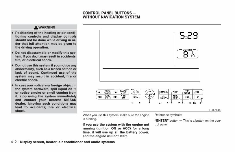
WARNING
● Positioning of the heating or air condi-tioning controls and display controlsshould not be done while driving in or-der that full attention may be given tothe driving operation.
● Do not disassemble or modify this sys-tem. If you do, it may result in accidents,fire, or electrical shock.
● Do not use this system if you notice anyabnormality, such as a frozen screen orlack of sound. Continued use of thesystem may result in accident, fire orelectric shock.
● In case you notice any foreign object inthe system hardware, spill liquid on it,or notice smoke or smell coming fromit, stop using the system immediatelyand contact your nearest NISSANdealer. Ignoring such conditions maylead to accidents, fire or electricalshock.
When you use this system, make sure the engineis running.
If you use the system with the engine notrunning (ignition ON or ACC) for a longtime, it will use up all the battery power,and the engine will not start.
Reference symbols:
“ENTER” button — This is a button on the con-trol panel.
LHA0249
CONTROL PANEL BUTTONS —WITHOUT NAVIGATION SYSTEM
4-2 Display screen, heater, air conditioner and audio systems
Z REVIEW COPY:—2004 Maxima (max)Owners Manual (owners)—USA English (nna)10/20/03—arosenma X
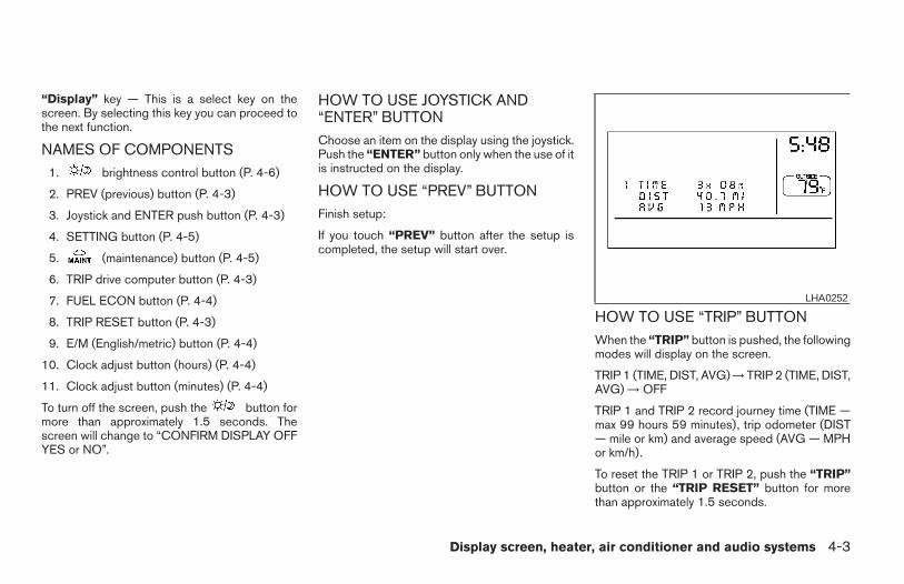
“Display” key — This is a select key on thescreen. By selecting this key you can proceed tothe next function.
NAMES OF COMPONENTS1. brightness control button (P. 4-6)
2. PREV (previous) button (P. 4-3)
3. Joystick and ENTER push button (P. 4-3)
4. SETTING button (P. 4-5)
5. (maintenance) button (P. 4-5)
6. TRIP drive computer button (P. 4-3)
7. FUEL ECON button (P. 4-4)
8. TRIP RESET button (P. 4-3)
9. E/M (English/metric) button (P. 4-4)
10. Clock adjust button (hours) (P. 4-4)
11. Clock adjust button (minutes) (P. 4-4)
To turn off the screen, push the button formore than approximately 1.5 seconds. Thescreen will change to “CONFIRM DISPLAY OFFYES or NO”.
HOW TO USE JOYSTICK AND“ENTER” BUTTONChoose an item on the display using the joystick.Push the “ENTER” button only when the use of itis instructed on the display.
HOW TO USE “PREV” BUTTONFinish setup:
If you touch “PREV” button after the setup iscompleted, the setup will start over.
HOW TO USE “TRIP” BUTTONWhen the “TRIP” button is pushed, the followingmodes will display on the screen.
TRIP 1 (TIME, DIST, AVG) → TRIP 2 (TIME, DIST,AVG) → OFF
TRIP 1 and TRIP 2 record journey time (TIME —max 99 hours 59 minutes), trip odometer (DIST— mile or km) and average speed (AVG — MPHor km/h).
To reset the TRIP 1 or TRIP 2, push the “TRIP”button or the “TRIP RESET” button for morethan approximately 1.5 seconds.
LHA0252
Display screen, heater, air conditioner and audio systems 4-3
Z REVIEW COPY:—2004 Maxima (max)Owners Manual (owners)—USA English (nna)10/20/03—arosenma X
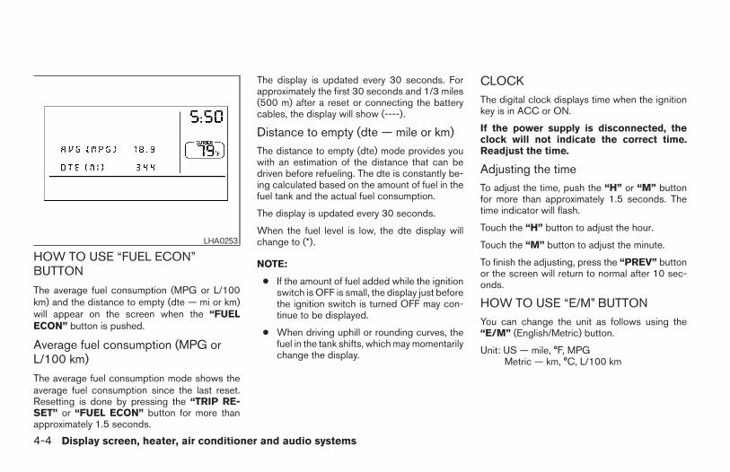
HOW TO USE “FUEL ECON”BUTTON
The average fuel consumption (MPG or L/100km) and the distance to empty (dte — mi or km)will appear on the screen when the “FUELECON” button is pushed.
Average fuel consumption (MPG orL/100 km)
The average fuel consumption mode shows theaverage fuel consumption since the last reset.Resetting is done by pressing the “TRIP RE-SET” or “FUEL ECON” button for more thanapproximately 1.5 seconds.
The display is updated every 30 seconds. Forapproximately the first 30 seconds and 1/3 miles(500 m) after a reset or connecting the batterycables, the display will show (----).
Distance to empty (dte — mile or km)The distance to empty (dte) mode provides youwith an estimation of the distance that can bedriven before refueling. The dte is constantly be-ing calculated based on the amount of fuel in thefuel tank and the actual fuel consumption.
The display is updated every 30 seconds.
When the fuel level is low, the dte display willchange to (*).
NOTE:
● If the amount of fuel added while the ignitionswitch is OFF is small, the display just beforethe ignition switch is turned OFF may con-tinue to be displayed.
● When driving uphill or rounding curves, thefuel in the tank shifts, which may momentarilychange the display.
CLOCKThe digital clock displays time when the ignitionkey is in ACC or ON.
If the power supply is disconnected, theclock will not indicate the correct time.Readjust the time.
Adjusting the timeTo adjust the time, push the “H” or “M” buttonfor more than approximately 1.5 seconds. Thetime indicator will flash.
Touch the “H” button to adjust the hour.
Touch the “M” button to adjust the minute.
To finish the adjusting, press the “PREV” buttonor the screen will return to normal after 10 sec-onds.
HOW TO USE “E/M” BUTTONYou can change the unit as follows using the“E/M” (English/Metric) button.
Unit: US — mile, °F, MPGMetric — km, °C, L/100 km
LHA0253
4-4 Display screen, heater, air conditioner and audio systems
Z REVIEW COPY:—2004 Maxima (max)Owners Manual (owners)—USA English (nna)10/07/03—tbrooks X
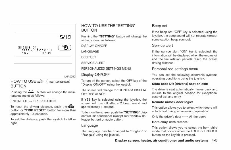
HOW TO USE (maintenance)BUTTONPushing the button will change the main-tenance menu as follows:
ENGINE OIL → TIRE ROTATION
To reset the driving distance, push thebutton or “TRIP RESET” button for more thanapproximately 1.5 seconds.
To set the distance, push the joystick to left orright.
HOW TO USE THE “SETTING”BUTTON
Pushing the “SETTING” button will change thesettings menu as follows:
DISPLAY ON/OFF
LANGUAGE
BEEP SET
SERVICE ALERT
PERSONALIZED SETTINGS MENU
Display ON/OFF
To turn off the screen, select the OFF key of the“Display ON/OFF” using the joystick.
The screen will change to “CONFIRM DISPLAYOFF YES or NO”.
If YES key is selected using the joystick, thescreen will turn off after a 2 beep sound andapproximately 1 second.
To turn on the screen, push the “SETTING” , tripcontrol, air conditioner (except rear window de-fogger button) or audio button.
LanguageThe language can be changed to “English” or“Français” using the joystick.
Beep set
If the beep set “OFF” key is selected using thejoystick, the beep sound will not operate (exceptsome caution beep sounds).
Service alert
If the service alert “ON” key is selected, theinformation will be displayed when the engine oiland the tire rotation periods reach the presetdriving distance.
Personalized settings menuYou can set the following electronic systemsoperating conditions using the joystick.
Slide back DR (driver’s) seat on exit:
The driver’s seat automatically moves back andreturns to the original position for exceptionalease of exit and entry.
Remote unlock door logic:
This option allows you to select which doors willunlock first during an unlocking operation:
Only the driver’s door ←→ All the doors
Horn chirp with remote:
This option allows you to select the horn chirpmode that occurs when the LOCK or UNLOCKbutton on the keyfob is pressed.
LHA0250
Display screen, heater, air conditioner and audio systems 4-5
Z REVIEW COPY:—2004 Maxima (max)Owners Manual (owners)—USA English (nna)10/07/03—tbrooks X
NOTE:
If you change the horn beep or the lampflash feature with the keyfob, the mode willnot be changed with the display. Use thekeyfob to return to the previous mode andre-enable the display control.
Lamps flash with remote:
This option allows you to select the hazard indi-cator flash mode that occurs when the LOCK orUNLOCK button on the keyfob is pressed.
NOTE:
If you change the horn beep or the lampflash feature with the keyfob, the mode willnot be changed with the display. Use thekeyfob to return to the previous mode andre-enable the display control.
Auto relock time:
This option allows you to set the length of timebefore the doors lock with the auto re-lock func-tion.
Auto headlamp sensitivity:
This option allows you to set the sensitivity of theautolights.
Auto headlamp off delay:
This option allows you to select the length of timebefore the autolights turn off.
Speed sensing wiper interval:
This option allows you to turn on or turn off thedriving speed dependent intermittent wiper func-tion.
Confirm reset settings:
This option allows you to reset all options to theirdefault settings.
BUTTONTo change the display brightness, pushthe button. Pushing the button again willchange the display to DAY or NIGHT display.Then, adjust the brightness moving the joystickright or left.
If no operation is done within 10 seconds, or if the“PREV” button is pushed, the display will returnto the previous display.
WARNING
● Positioning of the heating or air condi-tioning controls and display controlsshould not be done while driving in or-der that full attention may be given tothe driving operation.
● Do not disassemble or modify this sys-tem. If you do, it may result in accidents,fire, or electrical shock.
● Do not use this system if you notice anyabnormality, such as a frozen screen orlack of sound. Continued use of thesystem may result in accident, fire orelectric shock.
● In case you notice any foreign object inthe system hardware, spill liquid on it,or notice smoke or smell coming fromit, stop using the system immediatelyand contact your nearest NISSANdealer. Ignoring such conditions maylead to accidents, fire or electricalshock.
4-6 Display screen, heater, air conditioner and audio systems
Z REVIEW COPY:—2004 Maxima (max)Owners Manual (owners)—USA English (nna)10/07/03—tbrooks X
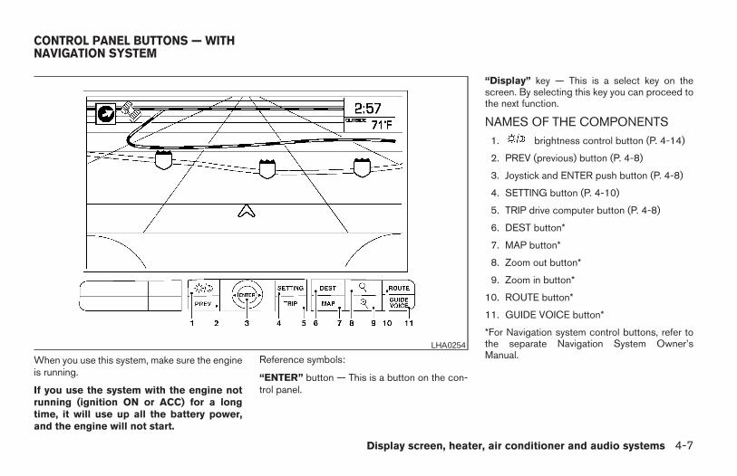
When you use this system, make sure the engineis running.
If you use the system with the engine notrunning (ignition ON or ACC) for a longtime, it will use up all the battery power,and the engine will not start.
Reference symbols:
“ENTER” button — This is a button on the con-trol panel.
“Display” key — This is a select key on thescreen. By selecting this key you can proceed tothe next function.
NAMES OF THE COMPONENTS1. brightness control button (P. 4-14)
2. PREV (previous) button (P. 4-8)
3. Joystick and ENTER push button (P. 4-8)
4. SETTING button (P. 4-10)
5. TRIP drive computer button (P. 4-8)
6. DEST button*
7. MAP button*
8. Zoom out button*
9. Zoom in button*
10. ROUTE button*
11. GUIDE VOICE button*
*For Navigation system control buttons, refer tothe separate Navigation System Owner’sManual.
LHA0254
CONTROL PANEL BUTTONS — WITHNAVIGATION SYSTEM
Display screen, heater, air conditioner and audio systems 4-7
Z REVIEW COPY:—2004 Maxima (max)Owners Manual (owners)—USA English (nna)10/20/03—arosenma X
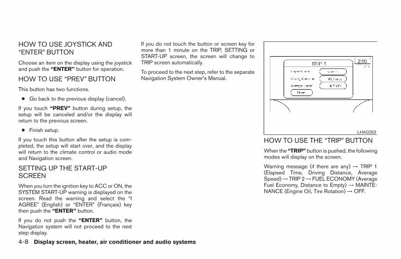
HOW TO USE JOYSTICK AND“ENTER” BUTTON
Choose an item on the display using the joystickand push the “ENTER” button for operation.
HOW TO USE “PREV” BUTTONThis button has two functions.
● Go back to the previous display (cancel).
If you touch “PREV” button during setup, thesetup will be canceled and/or the display willreturn to the previous screen.
● Finish setup.
If you touch this button after the setup is com-pleted, the setup will start over, and the displaywill return to the climate control or audio modeand Navigation screen.
SETTING UP THE START-UPSCREENWhen you turn the ignition key to ACC or ON, theSYSTEM START-UP warning is displayed on thescreen. Read the warning and select the “IAGREE” (English) or “ENTER” (Français) keythen push the “ENTER” button.
If you do not push the “ENTER” button, theNavigation system will not proceed to the nextstep display.
If you do not touch the button or screen key formore than 1 minute on the TRIP, SETTING orSTART-UP screen, the screen will change toTRIP screen automatically.
To proceed to the next step, refer to the separateNavigation System Owner’s Manual.
HOW TO USE THE “TRIP” BUTTONWhen the “TRIP” button is pushed, the followingmodes will display on the screen.
Warning message (if there are any) → TRIP 1(Elapsed Time, Driving Distance, AverageSpeed) → TRIP 2 → FUEL ECONOMY (AverageFuel Economy, Distance to Empty) → MAINTE-NANCE (Engine Oil, Tire Rotation) → OFF.
LHA0263
4-8 Display screen, heater, air conditioner and audio systems
Z REVIEW COPY:—2004 Maxima (max)Owners Manual (owners)—USA English (nna)10/07/03—tbrooks X
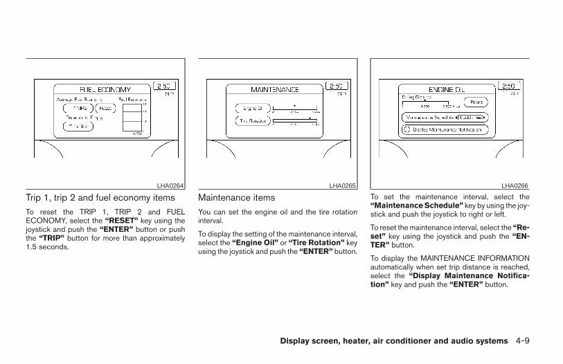
Trip 1, trip 2 and fuel economy itemsTo reset the TRIP 1, TRIP 2 and FUELECONOMY, select the “RESET” key using thejoystick and push the “ENTER” button or pushthe “TRIP” button for more than approximately1.5 seconds.
Maintenance itemsYou can set the engine oil and the tire rotationinterval.
To display the setting of the maintenance interval,select the “Engine Oil” or “Tire Rotation” keyusing the joystick and push the “ENTER” button.
To set the maintenance interval, select the“Maintenance Schedule” key by using the joy-stick and push the joystick to right or left.
To reset the maintenance interval, select the “Re-set” key using the joystick and push the “EN-TER” button.
To display the MAINTENANCE INFORMATIONautomatically when set trip distance is reached,select the “Display Maintenance Notifica-tion” key and push the “ENTER” button.
LHA0264 LHA0265 LHA0266
Display screen, heater, air conditioner and audio systems 4-9
Z REVIEW COPY:—2004 Maxima (max)Owners Manual (owners)—USA English (nna)10/07/03—tbrooks X
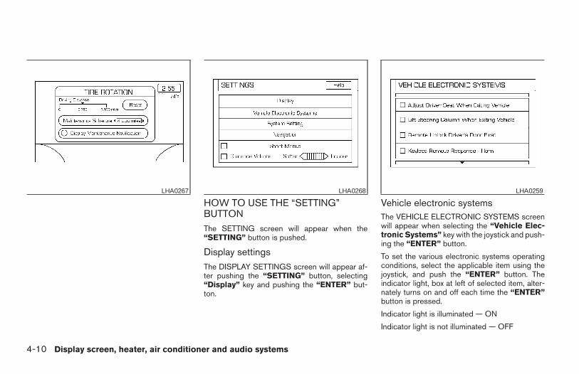
HOW TO USE THE “SETTING”BUTTONThe SETTING screen will appear when the“SETTING” button is pushed.
Display settingsThe DISPLAY SETTINGS screen will appear af-ter pushing the “SETTING” button, selecting“Display” key and pushing the “ENTER” but-ton.
Vehicle electronic systemsThe VEHICLE ELECTRONIC SYSTEMS screenwill appear when selecting the “Vehicle Elec-tronic Systems” key with the joystick and push-ing the “ENTER” button.
To set the various electronic systems operatingconditions, select the applicable item using thejoystick, and push the “ENTER” button. Theindicator light, box at left of selected item, alter-nately turns on and off each time the “ENTER”button is pressed.
Indicator light is illuminated — ON
Indicator light is not illuminated — OFF
LHA0267 LHA0268 LHA0259
4-10 Display screen, heater, air conditioner and audio systems
Z REVIEW COPY:—2004 Maxima (max)Owners Manual (owners)—USA English (nna)10/07/03—tbrooks X
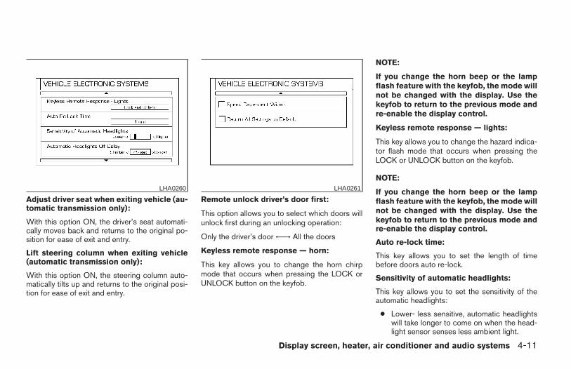
Adjust driver seat when exiting vehicle (au-tomatic transmission only):
With this option ON, the driver’s seat automati-cally moves back and returns to the original po-sition for ease of exit and entry.
Lift steering column when exiting vehicle(automatic transmission only):
With this option ON, the steering column auto-matically tilts up and returns to the original posi-tion for ease of exit and entry.
Remote unlock driver’s door first:
This option allows you to select which doors willunlock first during an unlocking operation:
Only the driver’s door ←→ All the doors
Keyless remote response — horn:
This key allows you to change the horn chirpmode that occurs when pressing the LOCK orUNLOCK button on the keyfob.
NOTE:
If you change the horn beep or the lampflash feature with the keyfob, the mode willnot be changed with the display. Use thekeyfob to return to the previous mode andre-enable the display control.
Keyless remote response — lights:
This key allows you to change the hazard indica-tor flash mode that occurs when pressing theLOCK or UNLOCK button on the keyfob.
NOTE:
If you change the horn beep or the lampflash feature with the keyfob, the mode willnot be changed with the display. Use thekeyfob to return to the previous mode andre-enable the display control.
Auto re-lock time:
This key allows you to set the length of timebefore doors auto re-lock.
Sensitivity of automatic headlights:
This key allows you to set the sensitivity of theautomatic headlights:
● Lower- less sensitive, automatic headlightswill take longer to come on when the head-light sensor senses less ambient light.
LHA0260 LHA0261
Display screen, heater, air conditioner and audio systems 4-11
Z REVIEW COPY:—2004 Maxima (max)Owners Manual (owners)—USA English (nna)10/07/03—tbrooks X
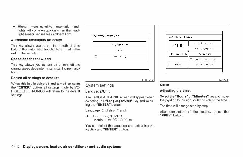
● Higher- more sensitive, automatic head-lights will come on quicker when the head-light sensor senses less ambient light.
Automatic headlights off delay:
This key allows you to set the length of timebefore the automatic headlights turn off afterexiting the vehicle.
Speed dependent wiper:
This key allows you to turn on or turn off thedriving speed dependent intermittent wiper func-tion.
Return all settings to default:
When this key is selected and turned on usingthe “ENTER” button, all settings made by VE-HICLE ELECTRONICS will return to the defaultsettings.
System settingsLanguage/Unit
The LANGUAGE/UNIT screen will appear whenselecting the “Language/Unit” key and push-ing the “ENTER” button.
Language: English or French
Unit: US — mile, °F, MPGMetric — km, °C, L/100 km
You can select the language and unit using thejoystick and “ENTER” button.
Clock
Adjusting the time:
Select the “Hours” or “Minutes” key and movethe joystick to the right or left to adjust the time.
The time will change step by step.
After completion of the setting, press the“PREV” button.
LHA0262 LHA0270
4-12 Display screen, heater, air conditioner and audio systems
Z REVIEW COPY:—2004 Maxima (max)Owners Manual (owners)—USA English (nna)10/07/03—tbrooks X
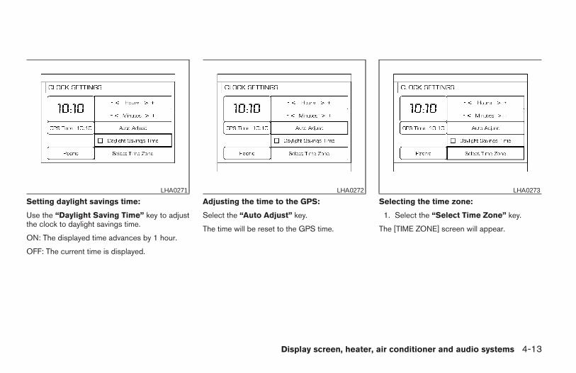
Setting daylight savings time:
Use the “Daylight Saving Time” key to adjustthe clock to daylight savings time.
ON: The displayed time advances by 1 hour.
OFF: The current time is displayed.
Adjusting the time to the GPS:
Select the “Auto Adjust” key.
The time will be reset to the GPS time.
Selecting the time zone:
1. Select the “Select Time Zone” key.
The [TIME ZONE] screen will appear.
LHA0271 LHA0272 LHA0273
Display screen, heater, air conditioner and audio systems 4-13
Z REVIEW COPY:—2004 Maxima (max)Owners Manual (owners)—USA English (nna)10/07/03—tbrooks X
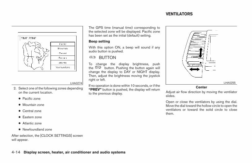
2. Select one of the following zones dependingon the current location.
● Pacific zone
● Mountain zone
● Central zone
● Eastern zone
● Atlantic zone
● Newfoundland zone
After selection, the [CLOCK SETTINGS] screenwill appear.
The GPS time (manual time) corresponding tothe selected zone will be displayed. Pacific zonehas been set as the initial (default) setting.
Beep setting
With this option ON, a beep will sound if anyaudio button is pushed.
BUTTONTo change the display brightness, pushthe button. Pushing the button again willchange the display to DAY or NIGHT display.Then, adjust the brightness moving the joystickright or left.
If no operation is done within 10 seconds, or if the“PREV” button is pushed, the display will returnto the previous display. Adjust air flow direction by moving the ventilator
slides.
Open or close the ventilators by using the dial.Move the dial toward the hollow circle to open theventilators or toward the solid circle to closethem.
LHA0274Center
LHA0255
VENTILATORS
4-14 Display screen, heater, air conditioner and audio systems
Z REVIEW COPY:—2004 Maxima (max)Owners Manual (owners)—USA English (nna)10/07/03—tbrooks X
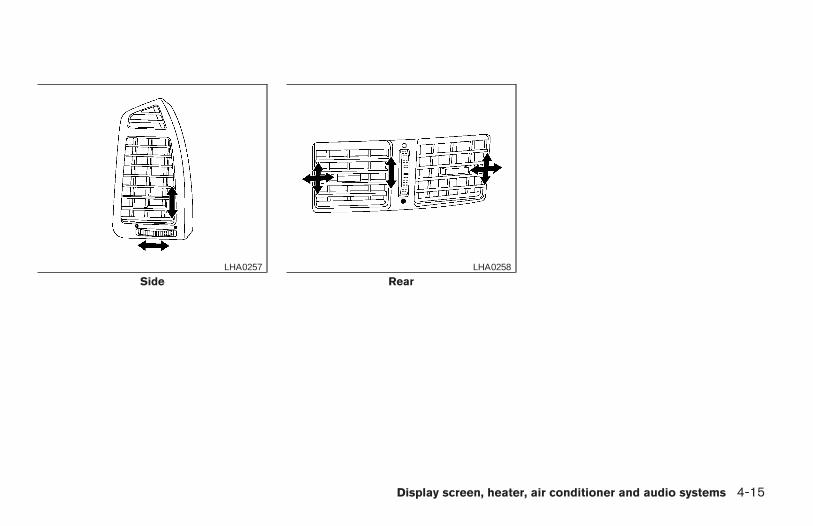
SideLHA0257
RearLHA0258
Display screen, heater, air conditioner and audio systems 4-15
Z REVIEW COPY:—2004 Maxima (max)Owners Manual (owners)—USA English (nna)10/07/03—tbrooks X
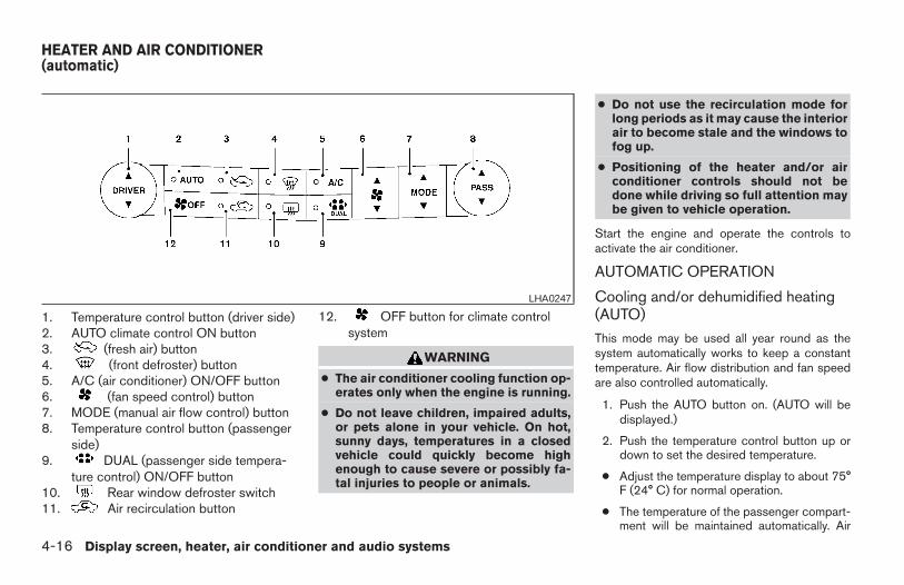
1. Temperature control button (driver side)2. AUTO climate control ON button3. (fresh air) button4. (front defroster) button5. A/C (air conditioner) ON/OFF button6. (fan speed control) button7. MODE (manual air flow control) button8. Temperature control button (passenger
side)9. DUAL (passenger side tempera-
ture control) ON/OFF button10. Rear window defroster switch11. Air recirculation button
12. OFF button for climate controlsystem
WARNING
● The air conditioner cooling function op-erates only when the engine is running.
● Do not leave children, impaired adults,or pets alone in your vehicle. On hot,sunny days, temperatures in a closedvehicle could quickly become highenough to cause severe or possibly fa-tal injuries to people or animals.
● Do not use the recirculation mode forlong periods as it may cause the interiorair to become stale and the windows tofog up.
● Positioning of the heater and/or airconditioner controls should not bedone while driving so full attention maybe given to vehicle operation.
Start the engine and operate the controls toactivate the air conditioner.
AUTOMATIC OPERATION
Cooling and/or dehumidified heating(AUTO)
This mode may be used all year round as thesystem automatically works to keep a constanttemperature. Air flow distribution and fan speedare also controlled automatically.
1. Push the AUTO button on. (AUTO will bedisplayed.)
2. Push the temperature control button up ordown to set the desired temperature.
● Adjust the temperature display to about 75°F (24° C) for normal operation.
● The temperature of the passenger compart-ment will be maintained automatically. Air
LHA0247
HEATER AND AIR CONDITIONER(automatic)
4-16 Display screen, heater, air conditioner and audio systems
Z REVIEW COPY:—2004 Maxima (max)Owners Manual (owners)—USA English (nna)10/07/03—tbrooks X
flow distribution and fan speed are also con-trolled automatically.
3. You can individually set driver and front pas-senger side temperature using each tem-perature control button. When the DUALbutton or passenger side temperature but-ton is pushed, the DUAL indicator will comeon. To turn off the passenger side tempera-ture control, push the DUAL button.
Heating (A/C OFF)
The air conditioner does not activate. When youneed to heat only, use this mode.
1. Push the A/C button. (A/C OFF will be dis-played and A/C indicator will turn off.)
2. Push the temperature control button up ordown to set the desired temperature.
● The temperature of the passenger compart-ment will be maintained automatically. Airflow distribution and fan speed are also con-trolled automatically.
● Do not set the temperature lower than theoutside air temperature. Otherwise the sys-tem may not work properly.
● Not recommended if windows fog up.
Dehumidified defrosting or defogging1. Push the defroster button on. The in-
dicator light on the button will come on.
2. Push the temperature control button up ordown to set the desired temperature.
● To quickly remove ice from the outside of thewindows, set the fan speed to maximum.
● As soon as possible after the windshield isclean, push the AUTO button to return to theautomatic mode.
● When the front defroster button is pushed,the air conditioner will automatically beturned on at outside temperatures above23°F (25°C). The air conditioning systemwill continue to operate until the fan controldial is turned to OFF or the vehicle is shut off,even if the air flow control button is used toselect a position other than position.This dehumidifies the air which helps defogthe windshield. The air recirculate mode au-tomatically turns off, allowing outside air tobe drawn into the passenger compartmentto further improve the defogging perfor-mance.
MANUAL OPERATIONFan speed control
Push the fan control button to manuallycontrol the fan speed.
Push the AUTO button to return to automaticcontrol of the fan speed.
Air recirculation
Push the air recirculation button to recirculateinterior air inside the vehicle. The indicator lighton the button will come on.
The air recirculation cannot be activated whenthe air conditioner is in the front defrosting mode.
Fresh airPush the button to draw outside air into thepassenger compartment. The indicator light onthe button will come on.
Automatic intake air controlIn the AUTO mode, the intake air will be con-trolled automatically. To manually control the in-take air, push the air recirculate or fresh air but-ton. To return to the automatic control mode,push the same button for about 2 seconds. Theindicator lights (both air recirculate and fresh airbuttons) will flash twice, and then the intake airwill be controlled automatically.
Display screen, heater, air conditioner and audio systems 4-17
Z REVIEW COPY:—2004 Maxima (max)Owners Manual (owners)—USA English (nna)10/07/03—tbrooks X
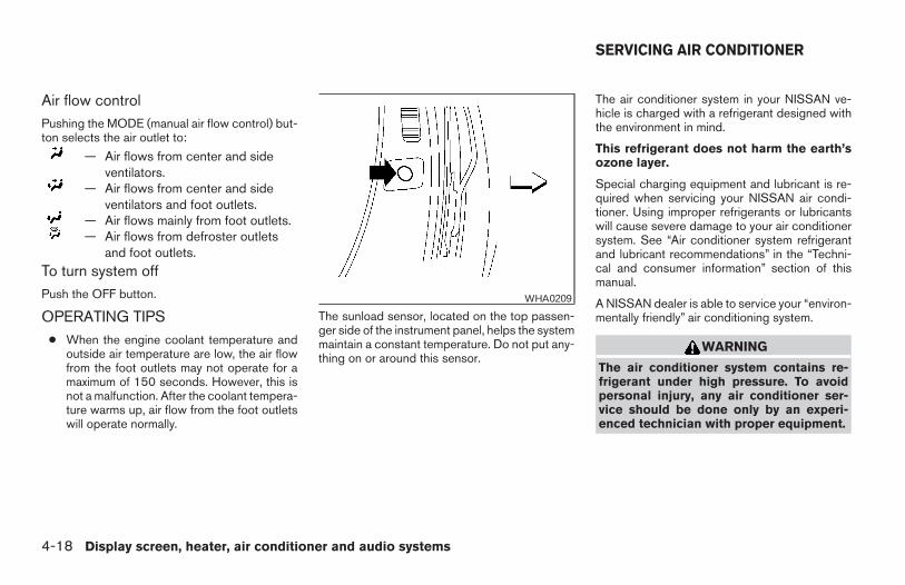
Air flow controlPushing the MODE (manual air flow control) but-ton selects the air outlet to:
— Air flows from center and sideventilators.
— Air flows from center and sideventilators and foot outlets.
— Air flows mainly from foot outlets.— Air flows from defroster outlets
and foot outlets.To turn system offPush the OFF button.
OPERATING TIPS● When the engine coolant temperature and
outside air temperature are low, the air flowfrom the foot outlets may not operate for amaximum of 150 seconds. However, this isnot a malfunction. After the coolant tempera-ture warms up, air flow from the foot outletswill operate normally.
The sunload sensor, located on the top passen-ger side of the instrument panel, helps the systemmaintain a constant temperature. Do not put any-thing on or around this sensor.
The air conditioner system in your NISSAN ve-hicle is charged with a refrigerant designed withthe environment in mind.
This refrigerant does not harm the earth’sozone layer.
Special charging equipment and lubricant is re-quired when servicing your NISSAN air condi-tioner. Using improper refrigerants or lubricantswill cause severe damage to your air conditionersystem. See “Air conditioner system refrigerantand lubricant recommendations” in the “Techni-cal and consumer information” section of thismanual.
A NISSAN dealer is able to service your “environ-mentally friendly” air conditioning system.
WARNING
The air conditioner system contains re-frigerant under high pressure. To avoidpersonal injury, any air conditioner ser-vice should be done only by an experi-enced technician with proper equipment.
WHA0209
SERVICING AIR CONDITIONER
4-18 Display screen, heater, air conditioner and audio systems
Z REVIEW COPY:—2004 Maxima (max)Owners Manual (owners)—USA English (nna)10/07/03—tbrooks X
RADIO
Turn the ignition key to the ACC or ON positionand press the PWR (power)/VOL (volume) knobto turn the radio on. If you listen to the radio withthe engine not running, the key should be turnedto the ACC position.
Radio reception is affected by station signalstrength, distance from radio transmitter, build-ings, bridges, mountains and other external influ-ences. Intermittent changes in reception qualitynormally are caused by these external influences.
Using a cellular phone in or near the ve-hicle may influence radio reception quality.
Radio reception
Your NISSAN radio system is equipped withstate-of-the-art electronic circuits to enhance ra-dio reception. These circuits are designed toextend reception range, and to enhance the qual-ity of that reception.
However there are some general characteristicsof both FM and AM radio signals that can affectradio reception quality in a moving vehicle, evenwhen the finest equipment is used. These char-acteristics are completely normal in a given re-ception area, and do not indicate any malfunctionin your NISSAN radio system.
Reception conditions will constantly change be-cause of vehicle movement. Buildings, terrain,signal distance and interference from other ve-hicles can work against ideal reception. De-scribed below are some of the factors that canaffect your radio reception.
FM RADIO RECEPTION
Range: FM range is normally limited to 25 - 30miles (40 - 48 km), with monaural (single chan-nel) FM having slightly more range than stereoFM. External influences may sometimes interferewith FM station reception even if the FM station iswithin 25 miles (40 km). The strength of the FMsignal is directly related to the distance betweenthe transmitter and receiver. FM signals follow aline-of-sight path, exhibiting many of the samecharacteristics as light. For example they willreflect off objects.
Fade and drift: As your vehicle moves away froma station transmitter, the signals will tend to fadeand/or drift.
Static and flutter: During signal interference frombuildings, large hills or due to antenna position(usually in conjunction with increased distancefrom the station transmitter) static or flutter canbe heard. This can be reduced by adjusting thetreble control to reduce treble response.
Multipath reception: Because of the reflectivecharacteristics of FM signals, direct and reflectedsignals reach the receiver at the same time. Thesignals may cancel each other, resulting in mo-mentary flutter or loss of sound.
AM RADIO RECEPTION
AM signals, because of their low frequency, canbend around objects and skip along the ground.In addition, the signals can be bounced off theionosphere and bent back to earth. Because ofthese characteristics, AM signals are also sub-ject to interference as they travel from transmitterto receiver.
Fading: Occurs while the vehicle is passingthrough freeway underpasses or in areas withmany tall buildings. It can also occur for severalseconds during ionospheric turbulence even inareas where no obstacles exist.
Static: Caused by thunderstorms, electricalpower lines, electric signs and even traffic lights.
SATELLITE RADIO RECEPTION
When the satellite radio is first installed or thebattery has been replaced, the satellite radio maynot work properly. This is not a malfunction. Waitmore than 10 minutes with satellite radio ON and
AUDIO SYSTEM
Display screen, heater, air conditioner and audio systems 4-19
Z REVIEW COPY:—2004 Maxima (max)Owners Manual (owners)—USA English (nna)10/07/03—tbrooks X
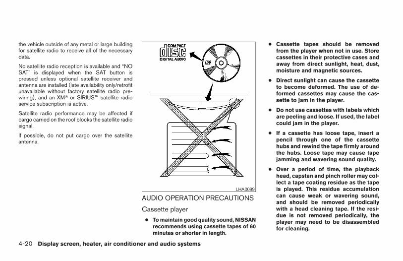
the vehicle outside of any metal or large buildingfor satellite radio to receive all of the necessarydata.
No satellite radio reception is available and “NOSAT” is displayed when the SAT button ispressed unless optional satellite receiver andantenna are installed (late availability only/retrofitunavailable without factory satellite radio pre-wiring), and an XMT or SIRIUS™ satellite radioservice subscription is active.
Satellite radio performance may be affected ifcargo carried on the roof blocks the satellite radiosignal.
If possible, do not put cargo over the satelliteantenna.
AUDIO OPERATION PRECAUTIONS
Cassette player
● To maintain good quality sound, NISSANrecommends using cassette tapes of 60minutes or shorter in length.
● Cassette tapes should be removedfrom the player when not in use. Storecassettes in their protective cases andaway from direct sunlight, heat, dust,moisture and magnetic sources.
● Direct sunlight can cause the cassetteto become deformed. The use of de-formed cassettes may cause the cas-sette to jam in the player.
● Do not use cassettes with labels whichare peeling and loose. If used, the labelcould jam in the player.
● If a cassette has loose tape, insert apencil through one of the cassettehubs and rewind the tape firmly aroundthe hubs. Loose tape may cause tapejamming and wavering sound quality.
● Over a period of time, the playbackhead, capstan and pinch roller may col-lect a tape coating residue as the tapeis played. This residue accumulationcan cause weak or wavering sound,and should be removed periodicallywith a head cleaning tape. If the resi-due is not removed periodically, theplayer may need to be disassembledfor cleaning.
LHA0099
4-20 Display screen, heater, air conditioner and audio systems
Z REVIEW COPY:—2004 Maxima (max)Owners Manual (owners)—USA English (nna)10/07/03—tbrooks X
Compact disc (CD) player● Only use high quality 4.7 inches (12 cm)
round discs that have the “COMPACTdisc DIGITAL AUDIO” logo on the discor packaging.
● During cold weather or rainy days, theplayer may malfunction due to the hu-midity. If this occurs, remove the CDand dehumidify or ventilate the playercompletely.
● The player may skip while driving onrough roads.
● The CD player sometimes cannot func-tion when the compartment tempera-ture is extremely high. Decrease thetemperature before use.
● Do not expose the CD to direct sun-light.
● CDs that are in poor condition or aredirty, scratched or covered with finger-prints may not work properly.
● The following CDs may not work prop-erly:
● Copy control compact discs (CCCD)
● Recordable compact discs (CD-R)
● Rewritable compact discs (CD-RW)
● Do not use the following CDs as theymay cause the CD player to malfunc-tion:
● 3.1 in (8 cm) discs with an adapter
● CDs that are not round
● CDs with a paper label
● CDs that are warped, scratched, orhave abnormal edges
Display screen, heater, air conditioner and audio systems 4-21
Z REVIEW COPY:—2004 Maxima (max)Owners Manual (owners)—USA English (nna)10/07/03—tbrooks X
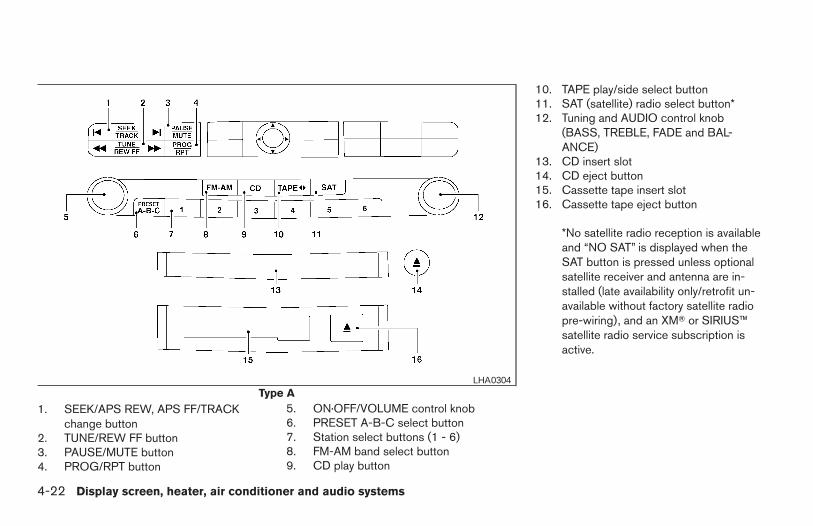
1. SEEK/APS REW, APS FF/TRACKchange button
2. TUNE/REW FF button3. PAUSE/MUTE button4. PROG/RPT button
5. ON·OFF/VOLUME control knob6. PRESET A-B-C select button7. Station select buttons (1 - 6)8. FM-AM band select button9. CD play button
10. TAPE play/side select button11. SAT (satellite) radio select button*12. Tuning and AUDIO control knob
(BASS, TREBLE, FADE and BAL-ANCE)
13. CD insert slot14. CD eject button15. Cassette tape insert slot16. Cassette tape eject button
*No satellite radio reception is availableand “NO SAT” is displayed when theSAT button is pressed unless optionalsatellite receiver and antenna are in-stalled (late availability only/retrofit un-available without factory satellite radiopre-wiring), and an XMT or SIRIUS™satellite radio service subscription isactive.
Type ALHA0304
4-22 Display screen, heater, air conditioner and audio systems
Z REVIEW COPY:—2004 Maxima (max)Owners Manual (owners)—USA English (nna)10/20/03—arosenma X
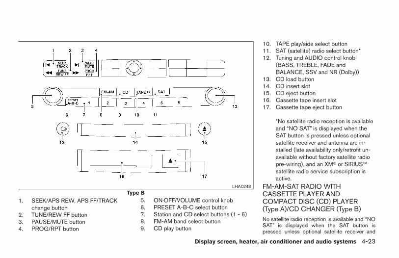
1. SEEK/APS REW, APS FF/TRACKchange button
2. TUNE/REW FF button3. PAUSE/MUTE button4. PROG/RPT button
5. ON·OFF/VOLUME control knob6. PRESET A-B-C select button7. Station and CD select buttons (1 - 6)8. FM-AM band select button9. CD play button
10. TAPE play/side select button11. SAT (satellite) radio select button*12. Tuning and AUDIO control knob
(BASS, TREBLE, FADE andBALANCE, SSV and NR (Dolby))
13. CD load button14. CD insert slot15. CD eject button16. Cassette tape insert slot17. Cassette tape eject button
*No satellite radio reception is availableand “NO SAT” is displayed when theSAT button is pressed unless optionalsatellite receiver and antenna are in-stalled (late availability only/retrofit un-available without factory satellite radiopre-wiring), and an XMT or SIRIUS™satellite radio service subscription isactive.
FM-AM-SAT RADIO WITHCASSETTE PLAYER ANDCOMPACT DISC (CD) PLAYER(Type A)/CD CHANGER (Type B)No satellite radio reception is available and “NOSAT” is displayed when the SAT button ispressed unless optional satellite receiver and
Type BLHA0248
Display screen, heater, air conditioner and audio systems 4-23
Z REVIEW COPY:—2004 Maxima (max)Owners Manual (owners)—USA English (nna)10/07/03—tbrooks X
antenna are installed (late availability only/retrofitunavailable without factory satellite radio pre-wiring), and an XMT or SIRIUS™ satellite radioservice subscription is active.
Audio main operation
The tape deck employs a permalloy head whichallows for improved reproduction of high fre-quency ranges. Noise is also greatly reduced bythe combined use of the Dolby NR (Noise Re-duction) system. The auto loudness circuit en-hances the low frequency range automatically inboth radio reception and tape and CD playback.
ON·OFF/Volume control:
Turn the ignition key to ACC or ON, and thenpush the ON·OFF/Volume control knob while thesystem is off to call up the mode (radio, tape orCD) which was playing immediately before thesystem was turned off.
To turn the system off, press the ON·OFF/Volumecontrol knob.
Turn the ON·OFF/Volume control knob to adjustthe volume.
This vehicle has speed sensitive control volume(SSV) for audio (type B only) . The audio volumechanges as the driving speed changes.
AUDIO knob (BASS, TREBLE, FADE, BAL-ANCE, (SSV and NR (Dolby) — Type Bonly)):
Press the AUDIO knob to change the mode asfollows:
BASS → TREBLE → FADE → BALANCE →SSV (Type B only) → NR (when cassette playing,Type B only)
To adjust Bass, Treble, Fade and Balance, pressthe AUDIO knob until the desired mode appearsin the display. Turn the Tuning knob to adjustBass and Treble to the desired level. You can alsouse the Tuning knob to adjust Fader and Balancemodes. Fader adjusts the sound level betweenthe front and rear speakers and Balance adjuststhe sound between the right and left speakers.
To change the SSV mode (Type B only) to OFF,LOW, MID or HIGH, turn the Tuning knob to rightor left.
To change the NR (Dolby) mode to OFF or ON,turn the Tuning knob to right or left while cassettetape is playing. When Dolby is ON, themark is displayed.
Dolby noise reduction manufactured under li-cense from Dolby Laboratories Licensing Corpo-ration. Dolby NR and the double-D symbolare trademarks of Dolby Laboratories LicensingCorporation.
Once you have adjusted the sound quality to thedesired level, press the AUDIO knob repeatedlyuntil the radio, cassette tape or CD display reap-pears. Otherwise, the radio, cassette tape or CDdisplay will automatically reappear after about 10seconds.
Display CD text:
To change the text displayed while playing a CD,press the AUDIO knob until “Display Mode” ap-pears.
Turn the Tuning knob within 2 seconds. The textwill change as follows:
Track number ←→ Track title ←→ Disc title ←→Track number
Display satellite radio text:
To change the text displayed while listening tosatellite radio, press the AUDIO knob until “Dis-play Mode” appears.
Turn the Tuning knob within 2 seconds. The textwill change as follows:
Channel number ←→ Channel name ←→ Artist←→ Title ←→ Channel number
Pause/mute button:
To mute or pause the audio sound, push thePAUSE/MUTE button.
4-24 Display screen, heater, air conditioner and audio systems
Z REVIEW COPY:—2004 Maxima (max)Owners Manual (owners)—USA English (nna)10/07/03—tbrooks X
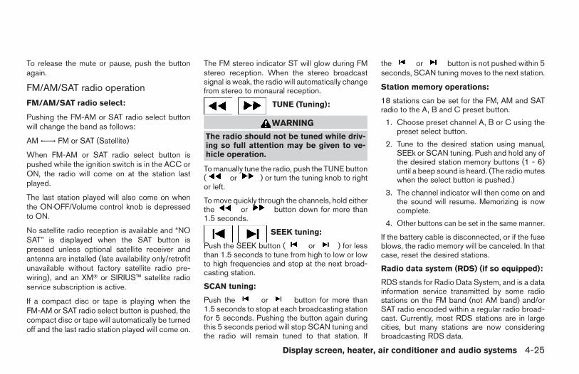
To release the mute or pause, push the buttonagain.
FM/AM/SAT radio operation
FM/AM/SAT radio select:
Pushing the FM-AM or SAT radio select buttonwill change the band as follows:
AM ←→ FM or SAT (Satellite)
When FM-AM or SAT radio select button ispushed while the ignition switch is in the ACC orON, the radio will come on at the station lastplayed.
The last station played will also come on whenthe ON·OFF/Volume control knob is depressedto ON.
No satellite radio reception is available and “NOSAT” is displayed when the SAT button ispressed unless optional satellite receiver andantenna are installed (late availability only/retrofitunavailable without factory satellite radio pre-wiring), and an XMT or SIRIUS™ satellite radioservice subscription is active.
If a compact disc or tape is playing when theFM-AM or SAT radio select button is pushed, thecompact disc or tape will automatically be turnedoff and the last radio station played will come on.
The FM stereo indicator ST will glow during FMstereo reception. When the stereo broadcastsignal is weak, the radio will automatically changefrom stereo to monaural reception.
TUNE (Tuning):
WARNING
The radio should not be tuned while driv-ing so full attention may be given to ve-hicle operation.
To manually tune the radio, push the TUNE button( or ) or turn the tuning knob to rightor left.
To move quickly through the channels, hold eitherthe or button down for more than1.5 seconds.
SEEK tuning:
Push the SEEK button ( or ) for lessthan 1.5 seconds to tune from high to low or lowto high frequencies and stop at the next broad-casting station.
SCAN tuning:
Push the or button for more than1.5 seconds to stop at each broadcasting stationfor 5 seconds. Pushing the button again duringthis 5 seconds period will stop SCAN tuning andthe radio will remain tuned to that station. If
the or button is not pushed within 5seconds, SCAN tuning moves to the next station.
Station memory operations:
18 stations can be set for the FM, AM and SATradio to the A, B and C preset button.
1. Choose preset channel A, B or C using thepreset select button.
2. Tune to the desired station using manual,SEEk or SCAN tuning. Push and hold any ofthe desired station memory buttons (1 - 6)until a beep sound is heard. (The radio muteswhen the select button is pushed.)
3. The channel indicator will then come on andthe sound will resume. Memorizing is nowcomplete.
4. Other buttons can be set in the same manner.
If the battery cable is disconnected, or if the fuseblows, the radio memory will be canceled. In thatcase, reset the desired stations.
Radio data system (RDS) (if so equipped):
RDS stands for Radio Data System, and is a datainformation service transmitted by some radiostations on the FM band (not AM band) and/orSAT radio encoded within a regular radio broad-cast. Currently, most RDS stations are in largecities, but many stations are now consideringbroadcasting RDS data.
Display screen, heater, air conditioner and audio systems 4-25
Z REVIEW COPY:—2004 Maxima (max)Owners Manual (owners)—USA English (nna)10/07/03—tbrooks X
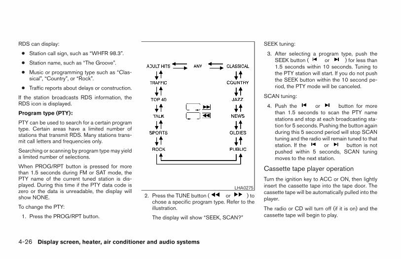
RDS can display:
● Station call sign, such as “WHFR 98.3”.
● Station name, such as “The Groove”.
● Music or programming type such as “Clas-sical”, “Country”, or “Rock”.
● Traffic reports about delays or construction.
If the station broadcasts RDS information, theRDS icon is displayed.
Program type (PTY):
PTY can be used to search for a certain programtype. Certain areas have a limited number ofstations that transmit RDS. Many stations trans-mit call letters and frequencies only.
Searching or scanning by program type may yielda limited number of selections.
When PROG/RPT button is pressed for morethan 1.5 seconds during FM or SAT mode, thePTY name of the current tuned station is dis-played. During this time if the PTY data code iszero or the data is unreadable, the display willshow NONE.
To change the PTY:
1. Press the PROG/RPT button.
2. Press the TUNE button ( or ) tochose a specific program type. Refer to theillustration.
The display will show “SEEK, SCAN?”
SEEK tuning:
3. After selecting a program type, push theSEEK button ( or ) for less than1.5 seconds within 10 seconds. Tuning tothe PTY station will start. If you do not pushthe SEEK button within the 10 second pe-riod, the PTY mode will be canceled.
SCAN tuning:
4. Push the or button for morethan 1.5 seconds to scan the PTY namestations and stop at each broadcasting sta-tion for 5 seconds. Pushing the button againduring this 5 second period will stop SCANtuning and the radio will remain tuned to thatstation. If the or button is notpushed within 5 seconds, SCAN tuningmoves to the next station.
Cassette tape player operation
Turn the ignition key to ACC or ON, then lightlyinsert the cassette tape into the tape door. Thecassette tape will be automatically pulled into theplayer.
The radio or CD will turn off (if it is on) and thecassette tape will begin to play.
LHA0275
4-26 Display screen, heater, air conditioner and audio systems
Z REVIEW COPY:—2004 Maxima (max)Owners Manual (owners)—USA English (nna)10/07/03—tbrooks X
WARNING
Do not force the cassette tape into thetape door. This could damage the player.
If the system is turned off by pushing theON·OFF/VOL control knob with the cassettetape still in the player, the tape will resume playingwhen the system is turned back on.
PLAY:
● When the TAPE button is pushed with thesystem turned off and a tape already loaded,the system will come on and the tape willplay.
● When the TAPE button is pushed with eitherthe radio or compact disc turned on and atape already loaded, the compact disc or theradio will automatically be turned off and thetape will play.
● When the TAPE button is pushed with aTAPE playing, the tape will play the programrecorded on the reverse side.
REW (Rewind), FF (FastForward):
Push the (rewind) button to rewind thetape. Push the (fast forward) button to fastforward the tape. Either the REW or FF symbolilluminates on the display window. To stop the
REW or FF function, press the (rewind)or (fast forward) again, or press the TAPEbutton.
APS (Automatic ProgramSearch) REW, APS FF:
When the (APS REW) button is pushedonce for less than 1.5 seconds while a tape isplaying, the program being played will start overfrom the beginning. Push the (APS REW)button several times to skip back several selec-tions. The tape will go back the number of timesthe button is pushed.
When the (APS FF) button is pushed forless than 1.5 seconds while a tape is playing, thenext program will start to play from the beginning.Push the (APS FF) button several times toskip through programs. The tape will advance thenumber of times the button is pushed (up to 9programs). Either the REW or FF symbol flasheson the display window while searching for theselection.
When pushing the (APS REW) or(APS FF) button for more than 1.5 seconds, eachprogram will play for about 10 seconds. To stopplaying, push the button again.
This system searches for the blank intervals be-tween selections. If there is a blank interval within
a program or there is no interval between pro-grams, the system may not stop in the desired orexpected location.
REPEAT (RPT):
When the PROG/RPT play button is pushedwhile the tape is played, the tape program play isrepeated. To stop the repeat play, push thePROG/RPT play button again.
Metal or chrome tape usage:
The cassette player will be automatically set tohigh performance play when playing a metal orchrome cassette tape.
TAPE EJECT:
When button is pushed with a tapeloaded, the tape will be ejected.
When a tape is ejected while it is being played,the system will be turned off.
Compact disc (CD) player operation(Type A)
CAUTION
● Do not force the compact disc into theslot. This could damage the player.
Display screen, heater, air conditioner and audio systems 4-27
Z REVIEW COPY:—2004 Maxima (max)Owners Manual (owners)—USA English (nna)10/07/03—tbrooks X
● Trying to load a CD with the CD doorclosed could damage the CD and/or CDchanger.
Turn the ignition key to the ACC or ON positionand insert the compact disc into the slot with thelabel side facing up. The compact disc will beguided automatically into the slot and start play-ing.
If the radio or tape is already operating, it willautomatically turn off and the compact disc willplay.
If the system has been turned off while the com-pact disc was playing, pushing the ON·OFF/VOLcontrol knob will start the compact disc.
3.1 in (8 cm) diameter compact discs can also beused without an adapter.
CD button: When the CD button is pushed withthe system off and the compact disc loaded, thesystem will turn on and the compact disc will startto play.
When the CD button is pushed with the compactdisc loaded but the tape or the radio playing, thetape or radio will automatically be turned off andthe compact disc will start to play.
REW (Rewind), FF (FastForward):
When the (rewind) button or (fastforward) is pushed while the compact disc isbeing played, the compact disc will play whilerewinding or fast forwarding. When the button isreleased, the compact disc will return to normalplay speed.
SEEK/TRACK:
When the button is pushed for less than1.5 seconds while a compact disc is playing, thetrack being played returns to its beginning. Pushseveral times to skip back through tracks. Thecompact disc will go back the number of timesthe button is pushed.
When the button is pushed for less than1.5 seconds while a compact disc is playing, thenext track will start to play from its beginning.Push several times to skip through tracks. Thecompact disc will advance the number of timesthe button is pushed. (When the last track on thecompact disc is skipped through, the first trackwill be played.)
When the or button is pushed formore than 1.5 seconds, each track will play forabout 10 seconds. To stop playing, pushthe button.
REPEAT (RPT):
When the PROG/RPT button is pushed while thecompact disc is being played, the play patterncan be changed as follows:
ALL DISC RPT → 1 TRACK RPT → 1 DISC RDM→ ALL DISC RPT
ALL DISC RPT: the entire disk will be repeated1 TRACK RPT: the current track will be repeated1 DISC RDM: all tracks will be played randomly
CD EJECT:
When the button is pushed with the com-pact disc loaded, the compact disc will beejected.
When button is pushed while the compactdisc is being played, the compact disc will ejectand the system will turn off.
If the compact disc ejects and is not re-moved, it will be pulled back into the slot toprotect it (except 3.1 in (8 cm) diametercompact discs).
CD IN indicator:
CD IN indicator appears on the display when theCD is loaded with the system on.
4-28 Display screen, heater, air conditioner and audio systems
Z REVIEW COPY:—2004 Maxima (max)Owners Manual (owners)—USA English (nna)10/07/03—tbrooks X
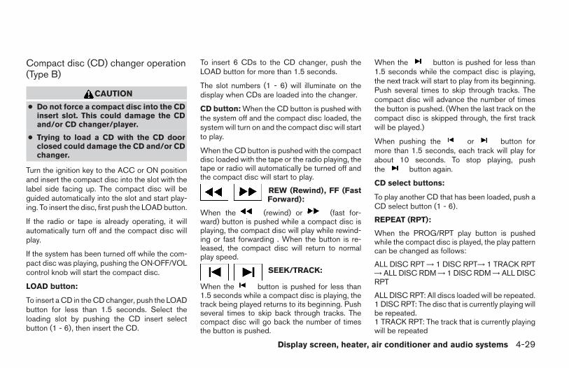
Compact disc (CD) changer operation(Type B)
CAUTION
● Do not force a compact disc into the CDinsert slot. This could damage the CDand/or CD changer/player.
● Trying to load a CD with the CD doorclosed could damage the CD and/or CDchanger.
Turn the ignition key to the ACC or ON positionand insert the compact disc into the slot with thelabel side facing up. The compact disc will beguided automatically into the slot and start play-ing. To insert the disc, first push the LOAD button.
If the radio or tape is already operating, it willautomatically turn off and the compact disc willplay.
If the system has been turned off while the com-pact disc was playing, pushing the ON·OFF/VOLcontrol knob will start the compact disc.
LOAD button:
To insert a CD in the CD changer, push the LOADbutton for less than 1.5 seconds. Select theloading slot by pushing the CD insert selectbutton (1 - 6), then insert the CD.
To insert 6 CDs to the CD changer, push theLOAD button for more than 1.5 seconds.
The slot numbers (1 - 6) will illuminate on thedisplay when CDs are loaded into the changer.
CD button: When the CD button is pushed withthe system off and the compact disc loaded, thesystem will turn on and the compact disc will startto play.
When the CD button is pushed with the compactdisc loaded with the tape or the radio playing, thetape or radio will automatically be turned off andthe compact disc will start to play.
REW (Rewind), FF (FastForward):
When the (rewind) or (fast for-ward) button is pushed while a compact disc isplaying, the compact disc will play while rewind-ing or fast forwarding . When the button is re-leased, the compact disc will return to normalplay speed.
SEEK/TRACK:
When the button is pushed for less than1.5 seconds while a compact disc is playing, thetrack being played returns to its beginning. Pushseveral times to skip back through tracks. Thecompact disc will go back the number of timesthe button is pushed.
When the button is pushed for less than1.5 seconds while the compact disc is playing,the next track will start to play from its beginning.Push several times to skip through tracks. Thecompact disc will advance the number of timesthe button is pushed. (When the last track on thecompact disc is skipped through, the first trackwill be played.)
When pushing the or button formore than 1.5 seconds, each track will play forabout 10 seconds. To stop playing, pushthe button again.
CD select buttons:
To play another CD that has been loaded, push aCD select button (1 - 6).
REPEAT (RPT):
When the PROG/RPT play button is pushedwhile the compact disc is played, the play patterncan be changed as follows:
ALL DISC RPT → 1 DISC RPT→ 1 TRACK RPT→ ALL DISC RDM → 1 DISC RDM → ALL DISCRPT
ALL DISC RPT: All discs loaded will be repeated.1 DISC RPT: The disc that is currently playing willbe repeated.1 TRACK RPT: The track that is currently playingwill be repeated
Display screen, heater, air conditioner and audio systems 4-29
Z REVIEW COPY:—2004 Maxima (max)Owners Manual (owners)—USA English (nna)10/07/03—tbrooks X
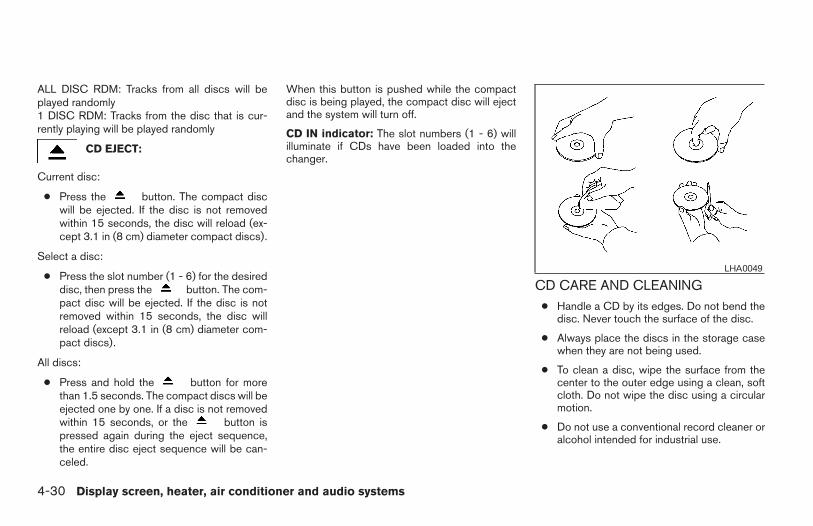
ALL DISC RDM: Tracks from all discs will beplayed randomly1 DISC RDM: Tracks from the disc that is cur-rently playing will be played randomly
CD EJECT:
Current disc:
● Press the button. The compact discwill be ejected. If the disc is not removedwithin 15 seconds, the disc will reload (ex-cept 3.1 in (8 cm) diameter compact discs).
Select a disc:
● Press the slot number (1 - 6) for the desireddisc, then press the button. The com-pact disc will be ejected. If the disc is notremoved within 15 seconds, the disc willreload (except 3.1 in (8 cm) diameter com-pact discs).
All discs:
● Press and hold the button for morethan 1.5 seconds. The compact discs will beejected one by one. If a disc is not removedwithin 15 seconds, or the button ispressed again during the eject sequence,the entire disc eject sequence will be can-celed.
When this button is pushed while the compactdisc is being played, the compact disc will ejectand the system will turn off.
CD IN indicator: The slot numbers (1 - 6) willilluminate if CDs have been loaded into thechanger.
CD CARE AND CLEANING● Handle a CD by its edges. Do not bend the
disc. Never touch the surface of the disc.
● Always place the discs in the storage casewhen they are not being used.
● To clean a disc, wipe the surface from thecenter to the outer edge using a clean, softcloth. Do not wipe the disc using a circularmotion.
● Do not use a conventional record cleaner oralcohol intended for industrial use.
LHA0049
4-30 Display screen, heater, air conditioner and audio systems
Z REVIEW COPY:—2004 Maxima (max)Owners Manual (owners)—USA English (nna)10/07/03—tbrooks X
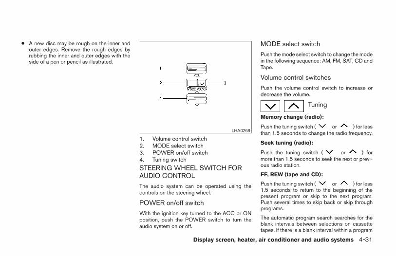
● A new disc may be rough on the inner andouter edges. Remove the rough edges byrubbing the inner and outer edges with theside of a pen or pencil as illustrated.
1. Volume control switch2. MODE select switch3. POWER on/off switch4. Tuning switch
STEERING WHEEL SWITCH FORAUDIO CONTROL
The audio system can be operated using thecontrols on the steering wheel.
POWER on/off switch
With the ignition key turned to the ACC or ONposition, push the POWER switch to turn theaudio system on or off.
MODE select switch
Push the mode select switch to change the modein the following sequence: AM, FM, SAT, CD andTape.
Volume control switches
Push the volume control switch to increase ordecrease the volume.
Tuning
Memory change (radio):
Push the tuning switch ( or ) for lessthan 1.5 seconds to change the radio frequency.
Seek tuning (radio):
Push the tuning switch ( or ) formore than 1.5 seconds to seek the next or previ-ous radio station.
FF, REW (tape and CD):
Push the tuning switch ( or ) for less1.5 seconds to return to the beginning of thepresent program or skip to the next program.Push several times to skip back or skip throughprograms.
The automatic program search searches for theblank intervals between selections on cassettetapes. If there is a blank interval within a program
LHA0269
Display screen, heater, air conditioner and audio systems 4-31
Z REVIEW COPY:—2004 Maxima (max)Owners Manual (owners)—USA English (nna)10/07/03—tbrooks X
or there is no interval between programs, thesystem may not stop in the desired or expectedlocation.
When playing a tape, push the tuning switch( or ) for more than 1.5 seconds torewind or fast forward the tape.
To stop the FF or REW function, press theor button for less than 1.5 seconds again.
When playing a CD in the CD changer (if soequipped), push the tuning switch (or ) for more than 1.5 seconds to changebetween discs when multiple CDs are loaded.
ANTENNA
Window antenna
The antenna pattern is printed inside the rearwindow.
CAUTION
● Do not place metalized film near therear window glass or attach any metalparts to it. This may cause poor recep-tion or noise.
● When cleaning the inside of the rearwindow, be careful not to scratch ordamage the rear window antenna.Lightly wipe along the antenna with adampened soft cloth.
When installing a CB, ham radio or car phone inyour NISSAN, be sure to observe the followingcautions, otherwise the new equipment may ad-versely affect the MFI (Multiport Fuel Injection)system and other electronic parts.
WARNING
● A cellular telephone should not be usedwhile driving so full attention may begiven to vehicle operation. Some juris-dictions prohibit the use of cellular tele-phones while driving.
● If you must make a call while your ve-hicle is in motion, the hands free cellu-lar phone operational mode (if soequipped) is highly recommended. Ex-ercise extreme caution at all times sofull attention may be given to vehicleoperation.
● If a conversation in a moving vehiclerequires you to take notes, pull off theroad to a safe location and stop yourvehicle before doing so.
CAUTION
● Keep the antenna as far away as pos-sible from the Engine Control Module(ECM).
CAR PHONE OR CB RADIO
4-32 Display screen, heater, air conditioner and audio systems
Z REVIEW COPY:—2004 Maxima (max)Owners Manual (owners)—USA English (nna)10/07/03—tbrooks X
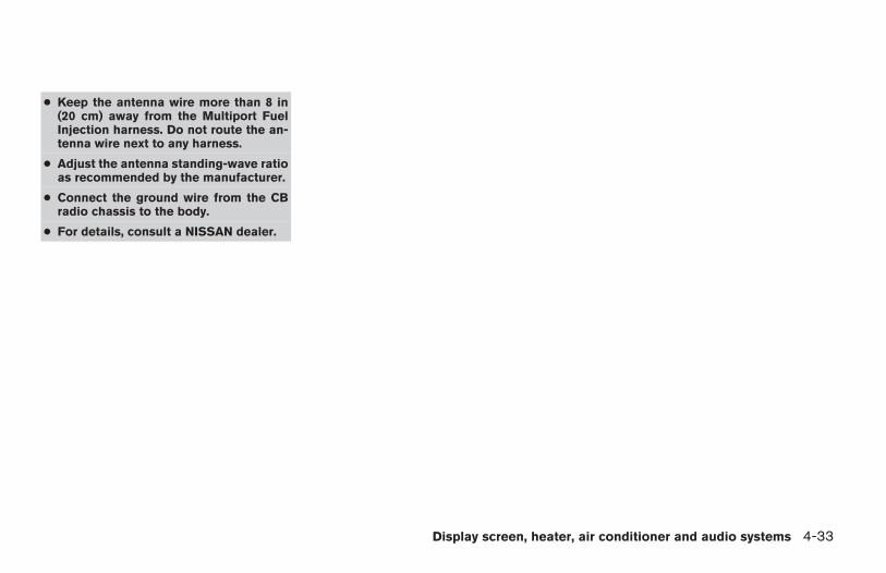
● Keep the antenna wire more than 8 in(20 cm) away from the Multiport FuelInjection harness. Do not route the an-tenna wire next to any harness.
● Adjust the antenna standing-wave ratioas recommended by the manufacturer.
● Connect the ground wire from the CBradio chassis to the body.
● For details, consult a NISSAN dealer.
Display screen, heater, air conditioner and audio systems 4-33
Z REVIEW COPY:—2004 Maxima (max)Owners Manual (owners)—USA English (nna)10/07/03—tbrooks X
4-34 Display screen, heater, air conditioner and audio systems
MEMO
5 Starting and driving
Precautions when starting and driving. . . . . . . . . . . . . . . . 5-2Exhaust gas (carbon monoxide) . . . . . . . . . . . . . . . . . . 5-2Three-way catalyst. . . . . . . . . . . . . . . . . . . . . . . . . . . . . . 5-2Avoiding collision and rollover . . . . . . . . . . . . . . . . . . . . 5-3Drinking alcohol/drugs and driving. . . . . . . . . . . . . . . . 5-3
Ignition switch. . . . . . . . . . . . . . . . . . . . . . . . . . . . . . . . . . . . . 5-4Automatic transmission. . . . . . . . . . . . . . . . . . . . . . . . . . 5-4Manual transmission . . . . . . . . . . . . . . . . . . . . . . . . . . . . 5-5Key positions . . . . . . . . . . . . . . . . . . . . . . . . . . . . . . . . . . 5-5Nissan vehicle immobilizer system (NVIS) . . . . . . . . . 5-5
Before starting the engine . . . . . . . . . . . . . . . . . . . . . . . . . . 5-6Starting the engine . . . . . . . . . . . . . . . . . . . . . . . . . . . . . . . . 5-6Driving the vehicle . . . . . . . . . . . . . . . . . . . . . . . . . . . . . . . . . 5-7
Automatic transmission (if so equipped). . . . . . . . . . . 5-7Manual transmission . . . . . . . . . . . . . . . . . . . . . . . . . . . 5-11
Parking brake . . . . . . . . . . . . . . . . . . . . . . . . . . . . . . . . . . . .5-12Cruise control (if so equipped) . . . . . . . . . . . . . . . . . . . . . 5-13
Precautions on cruise control . . . . . . . . . . . . . . . . . . . 5-13Cruise control operations. . . . . . . . . . . . . . . . . . . . . . . 5-14
Break-in schedule . . . . . . . . . . . . . . . . . . . . . . . . . . . . . . . .5-15Increasing fuel economy. . . . . . . . . . . . . . . . . . . . . . . . . . . 5-15Parking/parking on hills. . . . . . . . . . . . . . . . . . . . . . . . . . . .5-16Power steering . . . . . . . . . . . . . . . . . . . . . . . . . . . . . . . . . . .5-17Brake system . . . . . . . . . . . . . . . . . . . . . . . . . . . . . . . . . . . .5-18
Brake precautions . . . . . . . . . . . . . . . . . . . . . . . . . . . . .5-18Anti-lock brake system (ABS) . . . . . . . . . . . . . . . . . . . 5-18
Traction control system (TCS) (if so equipped) . . . . . . . 5-20Vehicle dynamic control (VDC) system(if so equipped) . . . . . . . . . . . . . . . . . . . . . . . . . . . . . . . . . .5-21Cold weather driving . . . . . . . . . . . . . . . . . . . . . . . . . . . . . .5-22
Freeing a frozen door lock . . . . . . . . . . . . . . . . . . . . . . 5-22Anti-freeze. . . . . . . . . . . . . . . . . . . . . . . . . . . . . . . . . . . .5-22Battery . . . . . . . . . . . . . . . . . . . . . . . . . . . . . . . . . . . . . . .5-22Draining of coolant water . . . . . . . . . . . . . . . . . . . . . . . 5-22Tire equipment . . . . . . . . . . . . . . . . . . . . . . . . . . . . . . . .5-22Special winter equipment. . . . . . . . . . . . . . . . . . . . . . . 5-23Driving on snow or ice . . . . . . . . . . . . . . . . . . . . . . . . . 5-23Engine block heater (if so equipped) . . . . . . . . . . . . . 5-23
Z REVIEW COPY:—2004 Maxima (max)Owners Manual (owners)—USA English (nna)10/20/03—arosenma X
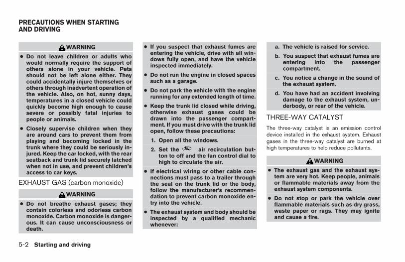
WARNING
● Do not leave children or adults whowould normally require the support ofothers alone in your vehicle. Petsshould not be left alone either. Theycould accidentally injure themselves orothers through inadvertent operation ofthe vehicle. Also, on hot, sunny days,temperatures in a closed vehicle couldquickly become high enough to causesevere or possibly fatal injuries topeople or animals.
● Closely supervise children when theyare around cars to prevent them fromplaying and becoming locked in thetrunk where they could be seriously in-jured. Keep the car locked, with the rearseatback and trunk lid securely latchedwhen not in use, and prevent children’saccess to car keys.
EXHAUST GAS (carbon monoxide)
WARNING
● Do not breathe exhaust gases; theycontain colorless and odorless carbonmonoxide. Carbon monoxide is danger-ous. It can cause unconsciousness ordeath.
● If you suspect that exhaust fumes areentering the vehicle, drive with all win-dows fully open, and have the vehicleinspected immediately.
● Do not run the engine in closed spacessuch as a garage.
● Do not park the vehicle with the enginerunning for any extended length of time.
● Keep the trunk lid closed while driving,otherwise exhaust gases could bedrawn into the passenger compart-ment. If you must drive with the trunk lidopen, follow these precautions:
1. Open all the windows.
2. Set the air recirculation but-ton to off and the fan control dial tohigh to circulate the air.
● If electrical wiring or other cable con-nections must pass to a trailer throughthe seal on the trunk lid or the body,follow the manufacturer’s recommen-dation to prevent carbon monoxide en-try into the vehicle.
● The exhaust system and body should beinspected by a qualified mechanicwhenever:
a. The vehicle is raised for service.
b. You suspect that exhaust fumes areentering into the passengercompartment.
c. You notice a change in the sound ofthe exhaust system.
d. You have had an accident involvingdamage to the exhaust system, un-derbody, or rear of the vehicle.
THREE-WAY CATALYST
The three-way catalyst is an emission controldevice installed in the exhaust system. Exhaustgases in the three-way catalyst are burned athigh temperatures to help reduce pollutants.
WARNING
● The exhaust gas and the exhaust sys-tem are very hot. Keep people, animalsor flammable materials away from theexhaust system components.
● Do not stop or park the vehicle overflammable materials such as dry grass,waste paper or rags. They may igniteand cause a fire.
PRECAUTIONS WHEN STARTINGAND DRIVING
5-2 Starting and driving
Z REVIEW COPY:—2004 Maxima (max)Owners Manual (owners)—USA English (nna)10/07/03—tbrooks X
CAUTION
● Do not use leaded gasoline. Depositsfrom leaded gasoline will seriously re-duce the three-way catalyst’s ability tohelp reduce exhaust pollutants.
● Keep your engine tuned up. Malfunc-tions in the ignition, fuel injection, orelectrical systems can cause overrichfuel flow into the three-way catalyst,causing it to overheat. Do not keep driv-ing if the engine misfires, or if notice-able loss of performance or other un-usual operating conditions aredetected. Have the vehicle inspectedpromptly by a NISSAN dealer.
● Avoid driving with an extremely low fuellevel. Running out of fuel could causethe engine to misfire, damaging thethree-way catalyst.
● Do not race the engine while warming itup.
● Do not push or tow your vehicle to startthe engine.
AVOIDING COLLISION ANDROLLOVER
WARNING
Failure to operate this vehicle in a safeand prudent manner may result in loss ofcontrol or an accident.
Be alert and drive defensively at all times. Obeyall traffic regulations. Avoid excessive speed,high speed cornering, or sudden steering ma-neuvers, because these driving practices couldcause you to lose control of your vehicle. As withany vehicle, loss of control could result in acollision with other vehicles or objects, orcause the vehicle to roll over, particularly ifthe loss of control causes the vehicle toslide sideways. Be attentive at all times, andavoid driving when tired. Never drive when underthe influence of alcohol or drugs (including pre-scription or over-the-counter drugs which maycause drowsiness). Always wear your seat beltas outlined in the “Safety – Seats, seat belts andsupplemental air bags” section of this manual,and also instruct your passengers to do so.
Seat belts help reduce the risk of injury in colli-sions and rollovers. In a rollover crash, anunbelted or improperly belted person issignificantly more likely to be injured orkilled than a person wearing a seat belt.
DRINKING ALCOHOL/DRUGS ANDDRIVING
WARNING
Never drive under the influence of alcoholor drugs. Alcohol in the bloodstream re-duces coordination, delays reaction timeand impairs judgement. Driving afterdrinking alcohol increases the likelihoodof being involved in an accident injuringyourself and others. Additionally, if youare injured in an accident, alcohol canincrease the severity of the injury.
NISSAN is committed to safe driving. However,you must choose not to drive under the influenceof alcohol. Every year thousands of people areinjured or killed in alcohol-related accidents. Al-though the local laws vary on what is consideredto be legally intoxicated, the fact is that alcoholaffects all people differently and most peopleunderestimate the effects of alcohol.
Remember, drinking and driving don’t mix! Andthat is true for drugs, too (over-the-counter, pre-scription, and illegal drugs). Don’t drive if yourability to operate your vehicle is impaired by alco-hol, drugs, or some other physical condition.
Starting and driving 5-3
Z REVIEW COPY:—2004 Maxima (max)Owners Manual (owners)—USA English (nna)10/07/03—tbrooks X
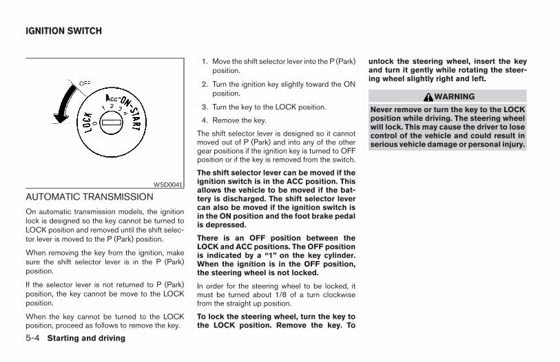
AUTOMATIC TRANSMISSION
On automatic transmission models, the ignitionlock is designed so the key cannot be turned toLOCK position and removed until the shift selec-tor lever is moved to the P (Park) position.
When removing the key from the ignition, makesure the shift selector lever is in the P (Park)position.
If the selector lever is not returned to P (Park)position, the key cannot be move to the LOCKposition.
When the key cannot be turned to the LOCKposition, proceed as follows to remove the key.
1. Move the shift selector lever into the P (Park)position.
2. Turn the ignition key slightly toward the ONposition.
3. Turn the key to the LOCK position.
4. Remove the key.
The shift selector lever is designed so it cannotmoved out of P (Park) and into any of the othergear positions if the ignition key is turned to OFFposition or if the key is removed from the switch.
The shift selector lever can be moved if theignition switch is in the ACC position. Thisallows the vehicle to be moved if the bat-tery is discharged. The shift selector levercan also be moved if the ignition switch isin the ON position and the foot brake pedalis depressed.
There is an OFF position between theLOCK and ACC positions. The OFF positionis indicated by a “1” on the key cylinder.When the ignition is in the OFF position,the steering wheel is not locked.
In order for the steering wheel to be locked, itmust be turned about 1/8 of a turn clockwisefrom the straight up position.
To lock the steering wheel, turn the key tothe LOCK position. Remove the key. To
unlock the steering wheel, insert the keyand turn it gently while rotating the steer-ing wheel slightly right and left.
WARNING
Never remove or turn the key to the LOCKposition while driving. The steering wheelwill lock. This may cause the driver to losecontrol of the vehicle and could result inserious vehicle damage or personal injury.
WSD0041
IGNITION SWITCH
5-4 Starting and driving
Z REVIEW COPY:—2004 Maxima (max)Owners Manual (owners)—USA English (nna)10/07/03—tbrooks X
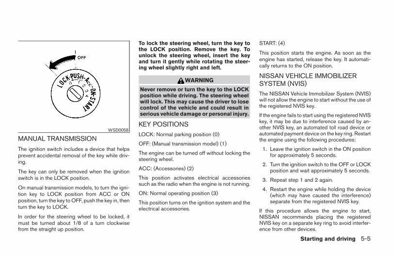
MANUAL TRANSMISSION
The ignition switch includes a device that helpsprevent accidental removal of the key while driv-ing.
The key can only be removed when the ignitionswitch is in the LOCK position.
On manual transmission models, to turn the igni-tion key to LOCK position from ACC or ONposition, turn the key to OFF, push the key in, thenturn the key to LOCK.
In order for the steering wheel to be locked, itmust be turned about 1/8 of a turn clockwisefrom the straight up position.
To lock the steering wheel, turn the key tothe LOCK position. Remove the key. Tounlock the steering wheel, insert the keyand turn it gently while rotating the steer-ing wheel slightly right and left.
WARNING
Never remove or turn the key to the LOCKposition while driving. The steering wheelwill lock. This may cause the driver to losecontrol of the vehicle and could result inserious vehicle damage or personal injury.
KEY POSITIONSLOCK: Normal parking position (0)
OFF: (Manual transmission model) (1)
The engine can be turned off without locking thesteering wheel.
ACC: (Accessories) (2)
This position activates electrical accessoriessuch as the radio when the engine is not running.
ON: Normal operating position (3)
This position turns on the ignition system and theelectrical accessories.
START: (4)
This position starts the engine. As soon as theengine has started, release the key. It automati-cally returns to the ON position.
NISSAN VEHICLE IMMOBILIZERSYSTEM (NVIS)The NISSAN Vehicle Immobilizer System (NVIS)will not allow the engine to start without the use ofthe registered NVIS key.
If the engine fails to start using the registered NVISkey, it may be due to interference caused by an-other NVIS key, an automated toll road device orautomated payment device on the key ring. Restartthe engine using the following procedures:
1. Leave the ignition switch in the ON positionfor approximately 5 seconds.
2. Turn the ignition switch to the OFF or LOCKposition and wait approximately 5 seconds.
3. Repeat step 1 and 2 again.
4. Restart the engine while holding the device(which may have caused the interference)separate from the registered NVIS key.
If this procedure allows the engine to start,NISSAN recommends placing the registeredNVIS key on a separate key ring to avoid interfer-ence from other devices.
WSD0058
Starting and driving 5-5
Z REVIEW COPY:—2004 Maxima (max)Owners Manual (owners)—USA English (nna)10/07/03—tbrooks X
● Make sure the area around the vehicle isclear.
● Check fluid levels such as engine oil, cool-ant, brake and clutch fluid, and windowwasher fluid as frequently as possible, or atleast whenever you refuel.
● Check that all windows and lights are clean.
● Visually inspect tires for their appearanceand condition. Also check tires for properinflation.
● Lock all doors.
● Position seat and adjust head restraints.
● Adjust inside and outside mirrors.
● Fasten seat belts and ask all passengers todo likewise.
● Check the operation of warning lights whenthe key is turned to the ON (3) position. See“Warning/indicator lights and audible re-minders” in the “Instruments and controls”section of this manual.
1. Apply the parking brake.
2. Automatic transmission:
Move the shift selector lever to P (Park) or N(Neutral). P (Park) is recommended.
The shift selector lever cannot bemoved out of P (Park) and into any ofthe other gear positions if the ignitionkey is turned to the OFF position or ifthe key is removed from the ignitionswitch.
The starter is designed not to operate ifthe shift selector lever is in any of thedriving positions.
Manual transmission:
Move the shift lever to N (Neutral). Depressthe clutch pedal to the floor while crankingthe engine.
The starter is designed not to operateunless the clutch pedal is fully de-pressed.
3. Crank the engine with your foot off theaccelerator pedal by turning the ignitionkey to START. Release the key when theengine starts. If the engine starts, but fails torun, repeat the above procedure.
● If the engine is very hard to start in ex-tremely cold weather or when restarting,depress the accelerator pedal a little (ap-proximately 1/3 to the floor) and hold itand then crank the engine. Release thekey and the accelerator pedal when theengine starts.
● If the engine is very hard to start becauseit is flooded, depress the acceleratorpedal all the way to the floor and hold it.Crank the engine for 5-6 seconds. Aftercranking the engine, release the accel-erator pedal. Crank the engine with yourfoot off the accelerator pedal by turn-ing the ignition key to START. Release thekey when the engine starts. If the enginestarts, but fails to run, repeat the aboveprocedure.
CAUTION
Do not operate the starter for more than15 seconds at a time. If the engine doesnot start, turn the key off and wait 10seconds before cranking again, otherwisethe starter could be damaged.
BEFORE STARTING THE ENGINE STARTING THE ENGINE
5-6 Starting and driving
Z REVIEW COPY:—2004 Maxima (max)Owners Manual (owners)—USA English (nna)10/07/03—tbrooks X
4. Allow the engine to idle for at least 30 sec-onds after starting. Do not race the enginewhile warming it up. Drive at moderatespeed for a short distance first, especially incold weather.
In cold weather, keep the engine running fora minimum of 2–3 minutes before shutting itoff. Starting and stopping the engine over ashort period of time may make the vehiclemore difficult to start.
AUTOMATIC TRANSMISSION (if soequipped)
WARNING
● Do not depress the accelerator pedalwhile shifting from P (Park) or N (Neu-tral) to R (Reverse), D (Drive), 2 or 1.Always depress the brake pedal untilshifting is completed. Failure to do socould cause you to lose control andhave an accident.
● Cold engine idle speed is high, so usecaution when shifting into a forward orreverse gear before the engine haswarmed up.
● Never shift to P (Park) or R (Reverse)while the vehicle is moving. This couldcause an accident.
CAUTION
● When stopping the vehicle on an uphillgrade, do not hold the vehicle by de-pressing the accelerator pedal. The footbrake should be used for this purpose.
● Do not downshift abruptly on slipperyroads. This may cause a loss of control.
The automatic transmission in your vehicle iselectronically controlled to produce maximumpower and smooth operation.
The recommended operating procedures for thistransmission are shown on the following pages.Follow these procedures for maximum vehicleperformance and driving enjoyment.
Starting the vehicle1. After starting the engine, fully depress the
foot brake pedal before attempting to movethe shift selector lever out of the P (Park)position.
2. Keep the foot brake pedal depressed andmove the shift selector lever into a drivinggear.
3. Release the foot brake, then gradually startthe vehicle in motion.
The automatic transmission is designed sothe foot brake pedal MUST be depressedbefore shifting from P (Park) to any driveposition while the ignition switch is in theON position.
The shift selector lever cannot be movedout of P (Park) and into any of the othergear positions if the ignition key is turnedto the LOCK, OFF or ACC position or if thekey is removed.
DRIVING THE VEHICLE
Starting and driving 5-7
Z REVIEW COPY:—2004 Maxima (max)Owners Manual (owners)—USA English (nna)10/07/03—tbrooks X
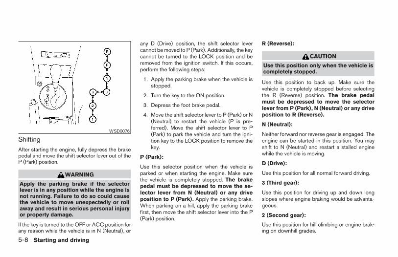
ShiftingAfter starting the engine, fully depress the brakepedal and move the shift selector lever out of theP (Park) position.
WARNING
Apply the parking brake if the selectorlever is in any position while the engine isnot running. Failure to do so could causethe vehicle to move unexpectedly or rollaway and result in serious personal injuryor property damage.
If the key is turned to the OFF or ACC position forany reason while the vehicle is in N (Neutral), or
any D (Drive) position, the shift selector levercannot be moved to P (Park). Additionally, the keycannot be turned to the LOCK position and beremoved from the ignition switch. If this occurs,perform the following steps:
1. Apply the parking brake when the vehicle isstopped.
2. Turn the key to the ON position.
3. Depress the foot brake pedal.
4. Move the shift selector lever to P (Park) or N(Neutral) to restart the vehicle (P is pre-ferred). Move the shift selector lever to P(Park) to park the vehicle and turn the igni-tion key to the LOCK position to remove thekey.
P (Park):
Use this selector position when the vehicle isparked or when starting the engine. Make surethe vehicle is completely stopped. The brakepedal must be depressed to move the se-lector lever from N (Neutral) or any driveposition to P (Park). Apply the parking brake.When parking on a hill, apply the parking brakefirst, then move the shift selector lever into the P(Park) position.
R (Reverse):
CAUTION
Use this position only when the vehicle iscompletely stopped.
Use this position to back up. Make sure thevehicle is completely stopped before selectingthe R (Reverse) position. The brake pedalmust be depressed to move the selectorlever from P (Park), N (Neutral) or any driveposition to R (Reverse).
N (Neutral):
Neither forward nor reverse gear is engaged. Theengine can be started in this position. You mayshift to N (Neutral) and restart a stalled enginewhile the vehicle is moving.
D (Drive):
Use this position for all normal forward driving.
3 (Third gear):
Use this position for driving up and down longslopes where engine braking would be advanta-geous.
2 (Second gear):
Use this position for hill climbing or engine brak-ing on downhill grades.
WSD0076
5-8 Starting and driving
Z REVIEW COPY:—2004 Maxima (max)Owners Manual (owners)—USA English (nna)10/07/03—tbrooks X
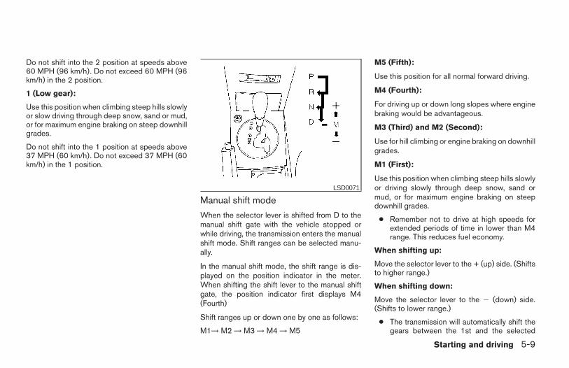
Do not shift into the 2 position at speeds above60 MPH (96 km/h). Do not exceed 60 MPH (96km/h) in the 2 position.
1 (Low gear):
Use this position when climbing steep hills slowlyor slow driving through deep snow, sand or mud,or for maximum engine braking on steep downhillgrades.
Do not shift into the 1 position at speeds above37 MPH (60 km/h). Do not exceed 37 MPH (60km/h) in the 1 position.
Manual shift mode
When the selector lever is shifted from D to themanual shift gate with the vehicle stopped orwhile driving, the transmission enters the manualshift mode. Shift ranges can be selected manu-ally.
In the manual shift mode, the shift range is dis-played on the position indicator in the meter.When shifting the shift lever to the manual shiftgate, the position indicator first displays M4(Fourth)
Shift ranges up or down one by one as follows:
M1→ M2 → M3 → M4 → M5
M5 (Fifth):
Use this position for all normal forward driving.
M4 (Fourth):
For driving up or down long slopes where enginebraking would be advantageous.
M3 (Third) and M2 (Second):
Use for hill climbing or engine braking on downhillgrades.
M1 (First):
Use this position when climbing steep hills slowlyor driving slowly through deep snow, sand ormud, or for maximum engine braking on steepdownhill grades.
● Remember not to drive at high speeds forextended periods of time in lower than M4range. This reduces fuel economy.
When shifting up:
Move the selector lever to the + (up) side. (Shiftsto higher range.)
When shifting down:
Move the selector lever to the 2 (down) side.(Shifts to lower range.)
● The transmission will automatically shift thegears between the 1st and the selected
LSD0071
Starting and driving 5-9
Z REVIEW COPY:—2004 Maxima (max)Owners Manual (owners)—USA English (nna)10/07/03—tbrooks X
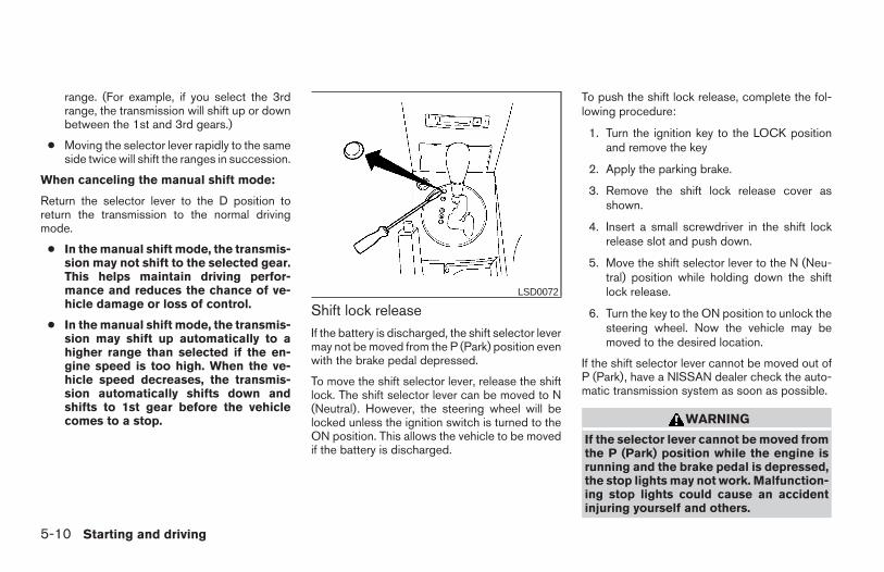
range. (For example, if you select the 3rdrange, the transmission will shift up or downbetween the 1st and 3rd gears.)
● Moving the selector lever rapidly to the sameside twice will shift the ranges in succession.
When canceling the manual shift mode:
Return the selector lever to the D position toreturn the transmission to the normal drivingmode.
● In the manual shift mode, the transmis-sion may not shift to the selected gear.This helps maintain driving perfor-mance and reduces the chance of ve-hicle damage or loss of control.
● In the manual shift mode, the transmis-sion may shift up automatically to ahigher range than selected if the en-gine speed is too high. When the ve-hicle speed decreases, the transmis-sion automatically shifts down andshifts to 1st gear before the vehiclecomes to a stop.
Shift lock releaseIf the battery is discharged, the shift selector levermay not be moved from the P (Park) position evenwith the brake pedal depressed.
To move the shift selector lever, release the shiftlock. The shift selector lever can be moved to N(Neutral). However, the steering wheel will belocked unless the ignition switch is turned to theON position. This allows the vehicle to be movedif the battery is discharged.
To push the shift lock release, complete the fol-lowing procedure:
1. Turn the ignition key to the LOCK positionand remove the key
2. Apply the parking brake.
3. Remove the shift lock release cover asshown.
4. Insert a small screwdriver in the shift lockrelease slot and push down.
5. Move the shift selector lever to the N (Neu-tral) position while holding down the shiftlock release.
6. Turn the key to the ON position to unlock thesteering wheel. Now the vehicle may bemoved to the desired location.
If the shift selector lever cannot be moved out ofP (Park), have a NISSAN dealer check the auto-matic transmission system as soon as possible.
WARNING
If the selector lever cannot be moved fromthe P (Park) position while the engine isrunning and the brake pedal is depressed,the stop lights may not work. Malfunction-ing stop lights could cause an accidentinjuring yourself and others.
LSD0072
5-10 Starting and driving
Z REVIEW COPY:—2004 Maxima (max)Owners Manual (owners)—USA English (nna)10/07/03—tbrooks X
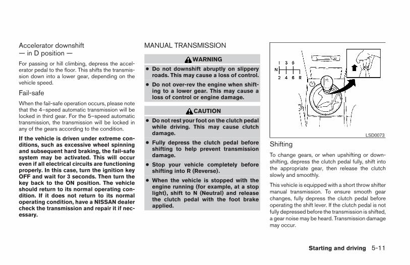
Accelerator downshift— in D position —For passing or hill climbing, depress the accel-erator pedal to the floor. This shifts the transmis-sion down into a lower gear, depending on thevehicle speed.
Fail-safeWhen the fail-safe operation occurs, please notethat the 4–speed automatic transmission will belocked in third gear. For the 5–speed automatictransmission, the transmission will be locked inany of the gears according to the condition.
If the vehicle is driven under extreme con-ditions, such as excessive wheel spinningand subsequent hard braking, the fail-safesystem may be activated. This will occureven if all electrical circuits are functioningproperly. In this case, turn the ignition keyOFF and wait for 3 seconds. Then turn thekey back to the ON position. The vehicleshould return to its normal operating con-dition. If it does not return to its normaloperating condition, have a NISSAN dealercheck the transmission and repair it if nec-essary.
MANUAL TRANSMISSION
WARNING
● Do not downshift abruptly on slipperyroads. This may cause a loss of control.
● Do not over-rev the engine when shift-ing to a lower gear. This may cause aloss of control or engine damage.
CAUTION
● Do not rest your foot on the clutch pedalwhile driving. This may cause clutchdamage.
● Fully depress the clutch pedal beforeshifting to help prevent transmissiondamage.
● Stop your vehicle completely beforeshifting into R (Reverse).
● When the vehicle is stopped with theengine running (for example, at a stoplight), shift to N (Neutral) and releasethe clutch pedal with the foot brakeapplied.
Shifting
To change gears, or when upshifting or down-shifting, depress the clutch pedal fully, shift intothe appropriate gear, then release the clutchslowly and smoothly.
This vehicle is equipped with a short throw shiftermanual transmission. To ensure smooth gearchanges, fully depress the clutch pedal beforeoperating the shift lever. If the clutch pedal is notfully depressed before the transmission is shifted,a gear noise may be heard. Transmission damagemay occur.
LSD0073
Starting and driving 5-11
Z REVIEW COPY:—2004 Maxima (max)Owners Manual (owners)—USA English (nna)10/07/03—tbrooks X
Start the vehicle in 1st gear and shift to 2nd, 3rd,4th and 5th up to 6th gear in sequence accordingto vehicle speed.
To back up, lift up on the reverse lever and thenmove it to the R (Reverse) position after stoppingthe vehicle completely.
If it is difficult to move the shift lever into R(Reverse) or 1 (1st), shift into N (Neutral), thenrelease the clutch pedal. Depress the clutchpedal again and shift into R (Reverse) or 1 (1st).
Suggested upshift speedsThe following are suggested vehicle speeds forshifting into a higher gear. These suggestionsrelate to fuel economy and vehicle performance.Actual upshift speeds will vary according to roadconditions, the weather and individual drivinghabits.
For quick acceleration in low altitude areas (lessthan 4,000 ft [1,219 m]) and normal accelera-tion in high altitude areas (over 4,000 ft[1,219 m]):
GEAR CHANGE MPH (km/h)1st to 2nd 15 (24)2nd to 3rd 25 (40)3rd to 4th 40 (64)4th to 5th 45 (72)5th to 6th 50 (80)
For quick acceleration in high altitude areas (over4,000 ft [1,219 m]):
GEAR CHANGE MPH (km/h)1st to 2nd 15 (24)2nd to 3rd 25 (40)3rd to 4th 40 (65)4th to 5th 45 (75)5th to 6th 50 (80)
Suggested maximum speed in each gearDownshift to a lower gear if the engine is notrunning smoothly, or if you need to accelerate.
Do not exceed the maximum suggested speed(shown below) in any gear. For level road driving,use the highest gear suggested for that speed.Always observe posted speed limits, and driveaccording to the road conditions, which will en-sure safe operation. Do not over-rev the enginewhen shifting to a lower gear as it may causeengine damage or loss of vehicle control.
GEAR MPH (km/h)
1st 35 (55)
2nd 60 (95)
3rd —
4th —
5th —
6th —
WARNING
● Be sure the parking brake is fully re-leased before driving. Failure to do socan cause brake failure and lead to anaccident.
● Do not release the parking brake fromoutside the vehicle.
● Do not use the gear shift in place of theparking brake. When parking, be surethe parking brake is fully engaged.
● Do not leave children unattended in avehicle. They could release the parkingbrake and cause an accident.
PARKING BRAKE
5-12 Starting and driving
Z REVIEW COPY:—2004 Maxima (max)Owners Manual (owners)—USA English (nna)10/07/03—tbrooks X
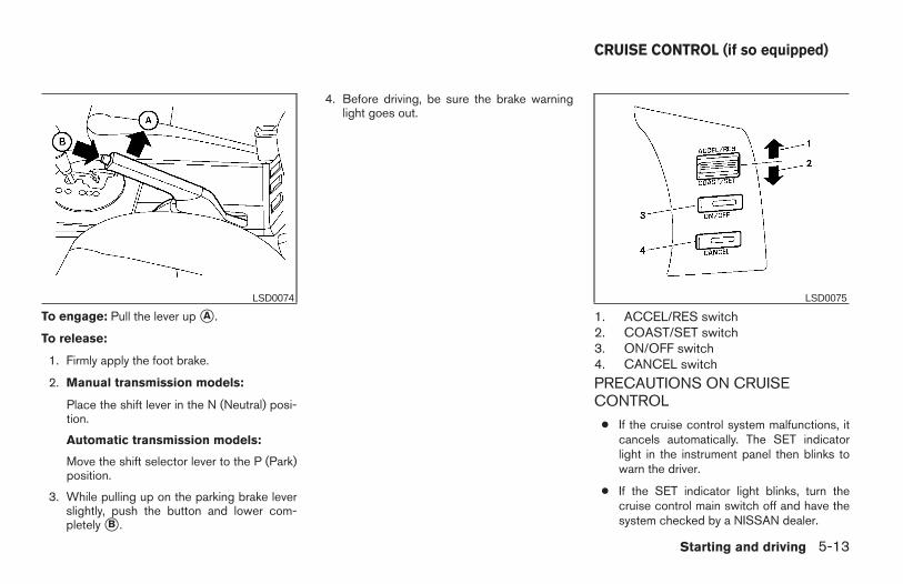
To engage: Pull the lever up sA .
To release:
1. Firmly apply the foot brake.
2. Manual transmission models:
Place the shift lever in the N (Neutral) posi-tion.
Automatic transmission models:
Move the shift selector lever to the P (Park)position.
3. While pulling up on the parking brake leverslightly, push the button and lower com-pletely sB .
4. Before driving, be sure the brake warninglight goes out.
1. ACCEL/RES switch2. COAST/SET switch3. ON/OFF switch4. CANCEL switch
PRECAUTIONS ON CRUISECONTROL
● If the cruise control system malfunctions, itcancels automatically. The SET indicatorlight in the instrument panel then blinks towarn the driver.
● If the SET indicator light blinks, turn thecruise control main switch off and have thesystem checked by a NISSAN dealer.
LSD0074 LSD0075
CRUISE CONTROL (if so equipped)
Starting and driving 5-13
Z REVIEW COPY:—2004 Maxima (max)Owners Manual (owners)—USA English (nna)10/07/03—tbrooks X
● The SET indicator light may blink when thecruise control main switch is turned ONwhile pushing the ACCEL/RES,COAST/SET, or CANCEL switch (locatedon the steering wheel). To properly set thecruise control system, use the following pro-cedures.
WARNING
Do not use the cruise control when drivingunder the following conditions:
● When it is not possible to keep thevehicle at a set speed.
● In heavy traffic or in traffic that varies inspeed.
● On winding or hilly roads.
● On slippery roads (rain, snow, ice, etc.).
● In very windy areas.
Doing so could cause a loss of vehiclecontrol and result in an accident.
CAUTION
On manual transmission models, do notshift into N (Neutral) without depressingthe clutch pedal when the cruise control isset. Should this occur, depress the clutchpedal and turn the main switch off imme-diately. Failure to do so may cause enginedamage.
CRUISE CONTROL OPERATIONSThe cruise control allows driving at a speed be-tween 30 - 90 MPH (48 - 144 km/h) withoutkeeping your foot on the accelerator pedal.
To turn on the cruise control, push the mainswitch. The CRUISE indicator light in the instru-ment panel comes on.
To set cruising speed, accelerate the vehicle tothe desired speed, push the COAST/SET switchand release it. The SET indicator light in theinstrument panel comes on. Take your foot off theaccelerator pedal. Your vehicle maintains the setspeed.
● To pass another vehicle, depress the ac-celerator pedal. When you release thepedal, the vehicle returns to the previouslyset speed.
● The vehicle may not maintain the set speedwhen going up or down steep hills. If thishappens, drive without the cruise control.
To cancel the preset speed, use one of thefollowing three methods.
● Push the CANCEL button; the SET indicatorlight in the instrument panel goes out.
● Tap the brake pedal; the SET indicator lightgoes out.
● Turn the main switch off. Both the CRUISEindicator light and SET indicator light in theinstrument panel go out.
The cruise control is automatically canceled andthe SET light in the instrument panel goes out if:
● you depress the brake or clutch pedal whilepushing the ACCEL/RES or SET/COASTswitch. The preset speed is deleted frommemory.
● the vehicle slows down more than 8 MPH(13 km/h) below the set speed.
● you depress the clutch pedal (manual trans-mission), or move the shift selector lever to N(Neutral) (automatic transmission).
5-14 Starting and driving
Z REVIEW COPY:—2004 Maxima (max)Owners Manual (owners)—USA English (nna)10/07/03—tbrooks X
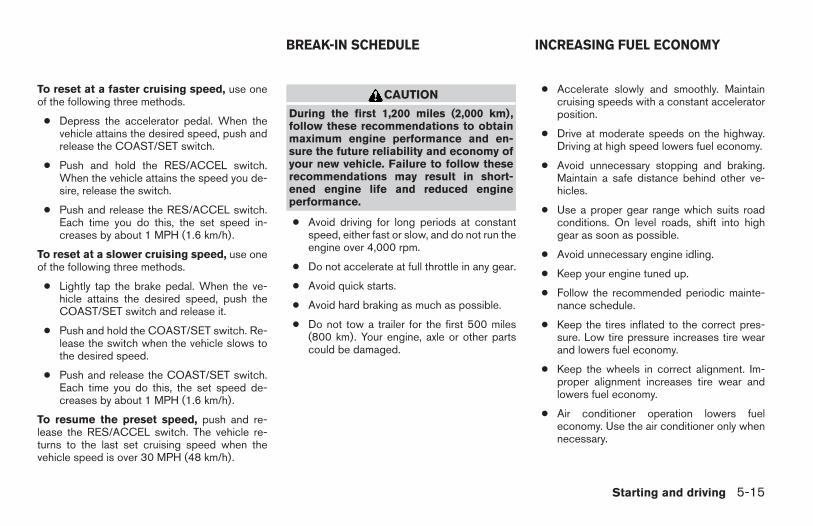
To reset at a faster cruising speed, use oneof the following three methods.
● Depress the accelerator pedal. When thevehicle attains the desired speed, push andrelease the COAST/SET switch.
● Push and hold the RES/ACCEL switch.When the vehicle attains the speed you de-sire, release the switch.
● Push and release the RES/ACCEL switch.Each time you do this, the set speed in-creases by about 1 MPH (1.6 km/h).
To reset at a slower cruising speed, use oneof the following three methods.
● Lightly tap the brake pedal. When the ve-hicle attains the desired speed, push theCOAST/SET switch and release it.
● Push and hold the COAST/SET switch. Re-lease the switch when the vehicle slows tothe desired speed.
● Push and release the COAST/SET switch.Each time you do this, the set speed de-creases by about 1 MPH (1.6 km/h).
To resume the preset speed, push and re-lease the RES/ACCEL switch. The vehicle re-turns to the last set cruising speed when thevehicle speed is over 30 MPH (48 km/h).
CAUTION
During the first 1,200 miles (2,000 km),follow these recommendations to obtainmaximum engine performance and en-sure the future reliability and economy ofyour new vehicle. Failure to follow theserecommendations may result in short-ened engine life and reduced engineperformance.
● Avoid driving for long periods at constantspeed, either fast or slow, and do not run theengine over 4,000 rpm.
● Do not accelerate at full throttle in any gear.
● Avoid quick starts.
● Avoid hard braking as much as possible.
● Do not tow a trailer for the first 500 miles(800 km). Your engine, axle or other partscould be damaged.
● Accelerate slowly and smoothly. Maintaincruising speeds with a constant acceleratorposition.
● Drive at moderate speeds on the highway.Driving at high speed lowers fuel economy.
● Avoid unnecessary stopping and braking.Maintain a safe distance behind other ve-hicles.
● Use a proper gear range which suits roadconditions. On level roads, shift into highgear as soon as possible.
● Avoid unnecessary engine idling.
● Keep your engine tuned up.
● Follow the recommended periodic mainte-nance schedule.
● Keep the tires inflated to the correct pres-sure. Low tire pressure increases tire wearand lowers fuel economy.
● Keep the wheels in correct alignment. Im-proper alignment increases tire wear andlowers fuel economy.
● Air conditioner operation lowers fueleconomy. Use the air conditioner only whennecessary.
BREAK-IN SCHEDULE INCREASING FUEL ECONOMY
Starting and driving 5-15
Z REVIEW COPY:—2004 Maxima (max)Owners Manual (owners)—USA English (nna)10/07/03—tbrooks X
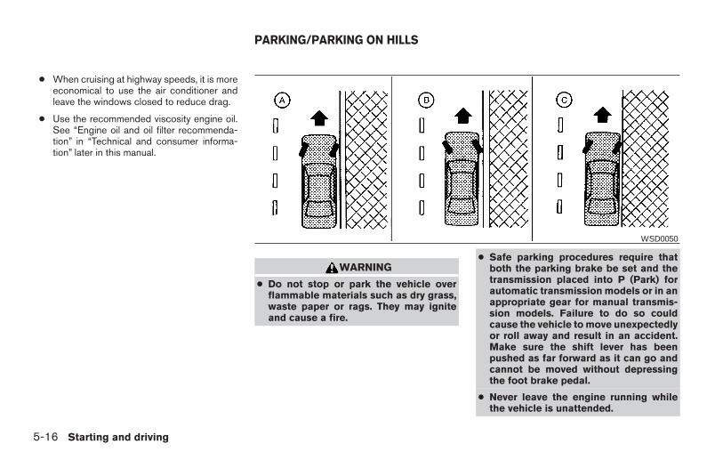
● When cruising at highway speeds, it is moreeconomical to use the air conditioner andleave the windows closed to reduce drag.
● Use the recommended viscosity engine oil.See “Engine oil and oil filter recommenda-tion” in “Technical and consumer informa-tion” later in this manual.
WARNING
● Do not stop or park the vehicle overflammable materials such as dry grass,waste paper or rags. They may igniteand cause a fire.
● Safe parking procedures require thatboth the parking brake be set and thetransmission placed into P (Park) forautomatic transmission models or in anappropriate gear for manual transmis-sion models. Failure to do so couldcause the vehicle to move unexpectedlyor roll away and result in an accident.Make sure the shift lever has beenpushed as far forward as it can go andcannot be moved without depressingthe foot brake pedal.
● Never leave the engine running whilethe vehicle is unattended.
WSD0050
PARKING/PARKING ON HILLS
5-16 Starting and driving
Z REVIEW COPY:—2004 Maxima (max)Owners Manual (owners)—USA English (nna)10/07/03—tbrooks X
● Do not leave children unattended insidethe vehicle. They could unknowingly ac-tivate switches or controls. Unattendedchildren could become involved in seri-ous accidents.
1. Firmly apply the parking brake.
2. Manual transmission models:
Place the shift lever in the R (Reverse) posi-tion. When parking on an uphill grade, placethe shift lever in 1st gear.
Automatic transmission models:
Move the shift selector lever to the P (Park)position.
3. To help prevent the vehicle from rolling intotraffic when parked on an incline, it is a goodpractice to turn the wheels as illustrated.
● HEADED DOWNHILL WITH CURB: sA
Turn the wheels into the curb and move thevehicle forward until the curb side wheelgently touches the curb.
● HEADED UPHILL WITH CURB: sB
Turn the wheels away from the curb andmove the vehicle back until the curb sidewheel gently touches the curb.
● HEADED UPHILL OR DOWNHILL, NOCURB: sC
Turn the wheels toward the side of the roadso the vehicle will move away from the cen-ter of the road if it moves.
4. Turn the ignition key to the LOCK positionand remove the key.
The power assisted steering is designed to use ahydraulic pump, driven by the engine, to assiststeering.
If the engine stops or the drive belt breaks, youwill still have control of the vehicle. However,much greater steering effort is needed, especiallyin sharp turns and at low speeds.
WARNING
If the engine is not running or is turned offwhile driving, the power assist for thesteering will not work. Steering will bemuch harder to operate.
POWER STEERING
Starting and driving 5-17
Z REVIEW COPY:—2004 Maxima (max)Owners Manual (owners)—USA English (nna)10/07/03—tbrooks X
The brake system has two separate hydrauliccircuits. If one circuit malfunctions, you will stillhave braking at two wheels.
BRAKE PRECAUTIONS
Vacuum assisted brakes
The brake booster aids braking by using enginevacuum. If the engine stops, you can stop thevehicle by depressing the brake pedal. However,greater foot pressure on the brake pedal will berequired to stop the vehicle and stopping dis-tance will be longer.
Using the brakes
Avoid resting your foot on the brake pedal whiledriving. This will overheat the brakes, wear out thebrake linings and pads faster, and reduce gasmileage.
To help reduce brake wear and to prevent thebrakes from overheating, reduce speed anddownshift to a lower gear before going down aslope or long grade. Overheated brakes mayreduce braking performance and could result inloss of vehicle control.
WARNING
● While driving on a slippery surface, becareful when braking, accelerating ordownshifting. Abrupt braking or accel-erating could cause the wheels to skidand result in an accident.
● If the engine is not running or is turnedoff while driving, the power assist forthe brakes will not work. Braking will beharder.
Wet brakes
When the vehicle is washed or driven throughwater, the brakes may get wet. As a result, yourbraking distance will be longer and the vehiclemay pull to one side during braking.
To dry the brakes, drive the vehicle at a safespeed while lightly pressing the brake pedal toheat up the brakes. Do this until the brakes returnto normal. Avoid driving the vehicle at highspeeds until the brakes function correctly.
Parking brake bedding
The parking brake shoes must be “bedded down”whenever the stopping effect of the parkingbrake is weakened or whenever the parking brakeshoes and/or drum/rotors are replaced, in orderto assure the best brake performance.
This procedure is described in the vehicle servicemanual and can be performed by a NISSANdealer.
ANTI-LOCK BRAKE SYSTEM (ABS)
The anti-lock brake system controls the brakes sothe wheels do not lock when braking abruptly orwhen braking on slippery surfaces. The systemdetects the rotation speed at each wheel andvaries the brake fluid pressure to prevent eachwheel from locking and sliding. By preventingwheel lockup, the system helps the driver main-tain steering control and helps to minimize swerv-ing and spinning on slippery surfaces.
Using the systemDepress the brake pedal and hold it down.
WARNING
Do not pump the brake pedal. Doing somay result in increased stoppingdistances.
Normal operationThe anti-lock brake system does not operate atspeeds below 3 - 6 MPH (5 - 10 km/h). (Thespeeds vary according to road conditions.)
When driving, the anti-lock brake system con-trols the wheels so they will not lock when brak-
BRAKE SYSTEM
5-18 Starting and driving
Z REVIEW COPY:—2004 Maxima (max)Owners Manual (owners)—USA English (nna)10/07/03—tbrooks X
ing abruptly or when braking on a slippery road.Thus, difficult steering and swerving of the ve-hicle due to locked wheels is minimized. Thesystem detects the wheel rotation rate and elec-tronically controls the pressure applied to eachbrake. Slight vibration on the brake pedal accom-panied by noise usually occurs while the ABSsystem is operating. Such vibration and noiseencountered during abrupt braking is not a prob-lem, but indicates that the system is functioningproperly. However, the pulsation may indicatethat road conditions are hazardous and extra careis required while driving.
Self-test feature
The anti-lock brake system consists of electronicsensors and hydraulic solenoids controlled by acomputer. The computer has a built-in diagnosticfeature that tests the system each time you startthe engine and move the vehicle at a low speed inforward or reverse. When the self-test occurs,you may hear a ‘‘clunk’’ noise and/or feel a pulsa-tion in the brake pedal. This is normal and is notan indication of any malfunction. If the computersenses any malfunction, it switches the anti-lockbrake system off and turns on the ABS brakewarning light on the instrument panel. The brakesystem then operates normally, but without anti-lock assistance.
If a malfunction occurs in the system, the anti-lock function will not operate, but the standardvehicle brake system will continue to operatenormally. The ABS brake warning light will thencome on.
If the light comes on during the self-test or whiledriving, take the vehicle to a NISSAN dealer forrepair.
WARNING
● The anti-lock brake system is a sophis-ticated device, but it cannot prevent ac-cidents resulting from careless or dan-gerous driving techniques. It can helpmaintain vehicle control during brakingon slippery surfaces, but remember thatthe stopping distance on slippery sur-faces will be longer than on normalsurfaces even with the anti-lock brakesystem. Stopping distances may alsobe longer on rough, gravel or snow cov-ered roads, or if you are using tirechains. Tire type and condition may alsoaffect braking effectiveness. Alwaysmaintain a safe distance from the ve-hicle in front of you. Ultimately, the re-sponsibility for safety of self and othersrests in the hands of the driver.
● Tire type and condition of tires may alsoaffect braking effectiveness.
● When replacing tires, install the speci-fied size of tires on all four wheels.
● When installing a spare tire, make sureit is the proper size and type as speci-fied on the tire placard. For tire placardlocation information, refer to “Tire plac-ard” in the “Technical and consumerinformation” section of this manual.
● Refer to “Wheels and tires” in the“Maintenance and do-it-yourself” sec-tion of this manual.
Starting and driving 5-19
Z REVIEW COPY:—2004 Maxima (max)Owners Manual (owners)—USA English (nna)10/07/03—tbrooks X
When accelerating on slippery surfaces the tiremay spin or slip. With the vehicle traction controlsystem, sensors detect these movements andcontrol the braking and engine output to helpimprove vehicle stability while accelerating.
● When the traction control system is operat-ing, the slip indicator in the instrument panelblinks.
● If the slip indicator blinks, the vehicle is un-der slippery conditions. Be sure to drivecarefully. See “Slip indicator light”and “Trac-tion control off indicator light” in the “Instru-ments and controls” section of this manual.
● If a malfunction occurs in the system,the and indicator lightscome on in the meter panel.
As long as these warning lights are on, the trac-tion control function is canceled. The vehicle willbehave like a vehicle without the system.
WARNING
● The traction control system is designedto help improve driving stability butdoes not prevent accidents due toabrupt steering operation at highspeeds or by careless or dangerousdriving techniques. Reduce vehiclespeed and be especially careful whendriving and cornering on slippery sur-faces and always drive carefully.
● If brake related parts such as brakepads, rotors and calipers are not stan-dard equipment or are extremely dete-riorated, the traction control systemmay not operate properly and theindicator light may come on.
● Do not modify the vehicle’s suspension.If suspension parts such as shock ab-sorbers, struts, springs and bushingsare not standard equipment or are ex-tremely deteriorated, the traction con-trol system may not operate properlyand the indicator light may comeon.
● When driving on extremely inclined sur-faces such as higher banked corners,the traction control system may not op-erate properly and the indicatorlight may come on. Do not drive onthese types of roads.
● If wheels or tires other than the recom-mended ones are used, the tractioncontrol system may not operate prop-erly and the indicator light maycome on.
● The traction control system is not a sub-stitute for winter tires or tire chains on asnow covered road.
TRACTION CONTROL SYSTEM (TCS)(if so equipped)
5-20 Starting and driving
Z REVIEW COPY:—2004 Maxima (max)Owners Manual (owners)—USA English (nna)10/07/03—tbrooks X
When accelerating or driving on slippery sur-faces, the tires may spin or slide. With the VehicleDynamic Control (VDC) system, sensors detectthese movements and control the braking andengine output to help improve vehicle stability.
● When the vehicle dynamic control (VDC)system is operating, the slip indicator in theinstrument panel blinks.
● When only the traction control system (TCS)portion of the vehicle dynamic control sys-tem is operating, the slip indicator will alsoblink.
● If the slip indicator blinks, the road condi-tions are slippery. Be sure to adjust yourspeed and driving to these conditions. See“Slip indicator light”, and “Vehicle dynamiccontrol off indicator light” in the “Instrumentsand controls” section.
● Indicator lightIf malfunction occurs in the system,the and indicator lights comeon in the instrument panel.As long as these warning lights are on, thetraction control function is canceled.
The VDC system uses an Active Brake LimitedSlip (ABLS) system to improve vehicle traction.The ABLS system works when one of the drivingwheels is spinning on a slippery surface. The
ABLS system brakes the spinning wheel whichdistributes the driving power to the other drivewheel. If the vehicle is operated with the vehicledynamic control system off, all VDC and TCSfunctions will be turned off. The ABLS systemand ABS will still operate with the VDC systemOFF. If the ABLS system or the ABS is activated,the slip indicator light will blink and you may heara clunk noise and/or feel a pulsation in the brakepedal. This is normal.
While the VDC system is operating, you may feela pulsation in the brake pedal and hear a noise orvibration from under the hood. This is normal andindicates that the VDC system is working prop-erly.
The computer has a built in diagnostic featurethat tests the system each time you start theengine and move the vehicle forward or in reverseat a slow speed. When the self-test occurs, youmay hear a clunk noise and/or feel a pulsation inthe brake pedal. This is normal and is not anindication of a malfunction.
WARNING
● The vehicle dynamic control system isdesigned to help improve driving stabil-ity but does not prevent accidents dueto abrupt steering operation at highspeeds or by careless or dangerousdriving techniques. Reduce vehiclespeed and be especially careful whendriving and cornering on slippery sur-faces and always drive carefully.
● If brake related parts such as brakepads, rotors and calipers are not stan-dard equipment or are extremely dete-riorated, the vehicle dynamic controlsystem may not operate properly andthe vehicle dynamic control off indica-tor light may come on.
● Do not modify the vehicle’s suspension.If suspension parts such as shock ab-sorbers, struts, springs, stabilizer barsand bushings are not NISSAN approvedfor your vehicle or are extremely dete-riorated the vehicle dynamic controlsystem may not operate properly. Thiscould adversely affect vehicle handlingperformance, and the vehicle dynamiccontrol off indicator light may come on.
VEHICLE DYNAMIC CONTROL (VDC)SYSTEM (if so equipped)
Starting and driving 5-21
Z REVIEW COPY:—2004 Maxima (max)Owners Manual (owners)—USA English (nna)10/07/03—tbrooks X
● When driving on extremely inclined sur-faces such as higher banked corners,the vehicle dynamic control system maynot operate properly and the vehicledynamic control off indicator light maycome on. Do not drive on these types ofroads.
● If wheels or tires other than the recom-mended ones are used, the vehicle dy-namic control system may not operateproperly and the vehicle dynamic con-trol off indicator light may come on.
● The vehicle dynamic control system isnot a substitute for winter tires or tirechains on a snow covered road.
FREEING A FROZEN DOOR LOCK
To prevent a door lock from freezing, apply de-icer through the key hole. If the lock becomesfrozen, heat the key before inserting it into the keyhole.
ANTI-FREEZE
In the winter when it is anticipated that the tem-perature will drop below 32°F (0°C), check theanti-freeze to assure proper winter protection.For details, see ‘‘Engine cooling system’’ in the‘‘Maintenance and do-it-yourself’’ section of thismanual.
BATTERY
If the battery is not fully charged during extremelycold weather conditions, the battery fluid mayfreeze and damage the battery. To maintain maxi-mum efficiency, the battery should be checkedregularly. For details, see ‘‘Battery’’ in the ‘‘Main-tenance and do-it-yourself’’ section of thismanual.
DRAINING OF COOLANT WATER
If the vehicle is to be left outside without anti-freeze, drain the cooling system, including theengine block. Refill before operating the vehicle.
For details, see ‘‘Changing engine coolant’’ in the‘‘Maintenance and do-it-yourself’’ section of thismanual.
TIRE EQUIPMENT1. SUMMER tires have a tread designed to
provide superior performance on dry pave-ment. However, the performance of thesetires will be substantially reduced in snowyand icy conditions. If you operate your ve-hicle on snowy or icy roads, NISSAN recom-mends the use of MUD & SNOW or ALLSEASON TIRES on all four wheels. Pleaseconsult a NISSAN dealer for the tire type,size, speed rating and availability informa-tion.
2. For additional traction on icy roads, studdedtires may be used. However, some U.S.states and Canadian provinces prohibit theiruse. Check local, state and provincial lawsbefore installing studded tires.
Skid and traction capabilities of studdedsnow tires on wet or dry surfaces may bepoorer than that of non-studded snow tires.
3. Tire chains may be used.
Use of tire chains may be prohibited accord-ing to location. Check the local laws beforeinstalling tire chains. When installing tirechains, make sure they are of proper size for
COLD WEATHER DRIVING
5-22 Starting and driving
Z REVIEW COPY:—2004 Maxima (max)Owners Manual (owners)—USA English (nna)10/07/03—tbrooks X
the tires on your vehicle and are installedaccording to the chain manufacturer’s sug-gestions. Use only SAE Class “S”chains. Class “S” chains are used on ve-hicles with restricted tire to vehicle clear-ance. Vehicles that can use Class “S”chainsare designed to meet the minimum clear-ances between the tire and the closest ve-hicle suspension or body component re-quired to accommodate the use of a wintertraction device (tire chains or cables). Theminimum clearances are determined usingthe factory equipped tire size. Other typesmay damage your vehicle. Use chain ten-sioners when recommended by the tirechain manufacturer to ensure a tight fit.Loose end links of the tire chain must besecured or removed to prevent the possibil-ity of whipping action damage to the fendersor underbody. If possible, avoid fully loadingyour vehicle when using tire chains. In addi-tion, drive at a reduced speed. Otherwise,your vehicle may be damaged and/or vehiclehandling and performance may be adverselyaffected.
Never install tire chains on spare tires. Donot use tire chains on dry roads.
SPECIAL WINTER EQUIPMENT
It is recommended that the following items becarried in the vehicle during winter:
● A scraper and stiff-bristled brush to removeice and snow from the windows and wiperblades.
● A sturdy, flat board to be placed under thejack to give it firm support.
● A shovel to dig the vehicle out of snowdrifts.
● Extra window washer fluid to refill the reser-voir tank.
DRIVING ON SNOW OR ICE
WARNING
● Wet ice (32°F, 0°C and freezing rain),very cold snow or ice can be slick andvery hard to drive on. The vehicle willhave much less traction or “grip” underthese conditions. Try to avoid driving onwet ice until the road is salted orsanded.
● Whatever the condition, drive with cau-tion. Accelerate and slow down withcare. If accelerating or downshifting toofast, the drive wheels will lose evenmore traction.
● Allow more stopping distance underthese conditions. Braking should bestarted sooner than on dry pavement.
● Allow greater following distances onslippery roads.
● Watch for slippery spots (glare ice).These may appear on an otherwise clearroad in shaded areas. If a patch of ice isseen ahead, brake before reaching it. Trynot to brake while on the ice, and avoidany sudden steering maneuvers.
● Do not use the cruise control on slip-pery roads.
● Snow can trap dangerous exhaustgases under your vehicle. Keep snowclear of the exhaust pipe and fromaround your vehicle.
ENGINE BLOCK HEATER (if soequipped)An engine block heater to assist in extreme coldtemperature starting is available through aNISSAN dealer.
WARNING
Do not use your heater with an ungroundedelectrical system or two-pronged (cheater)adapters. You can be injured by an electricalshock if you use an ungrounded connection.
Starting and driving 5-23
Z REVIEW COPY:—2004 Maxima (max)Owners Manual (owners)—USA English (nna)10/07/03—tbrooks X

5-24 Starting and driving
MEMO
6 In case of emergency
Flat tire . . . . . . . . . . . . . . . . . . . . . . . . . . . . . . . . . . . . . . . . . . . 6-2Changing a flat tire . . . . . . . . . . . . . . . . . . . . . . . . . . . . . 6-2
Jump starting . . . . . . . . . . . . . . . . . . . . . . . . . . . . . . . . . . . . . 6-6Push starting. . . . . . . . . . . . . . . . . . . . . . . . . . . . . . . . . . . . . . 6-8
If your vehicle overheats . . . . . . . . . . . . . . . . . . . . . . . . . . . . 6-9Towing your vehicle . . . . . . . . . . . . . . . . . . . . . . . . . . . . . . .6-10
Towing recommended by NISSAN . . . . . . . . . . . . . . 6-10Vehicle recovery (freeing a stuck vehicle) . . . . . . . . . 6-11
Z REVIEW COPY:—2004 Maxima (max)Owners Manual (owners)—USA English (nna)10/20/03—arosenma X
CHANGING A FLAT TIRE
If you have a flat tire, follow the instructions be-low.
Stopping the vehicle
1. Safely move the vehicle off the road andaway from traffic.
2. Turn on the hazard warning flashers.
3. Park on a level surface and apply the parkingbrake. Shift the manual transmission into R(Reverse), or the automatic transmissioninto P (Park).
4. Turn off the engine.
5. Raise the hood to warn other traffic and tosignal professional road assistance person-nel that you need assistance.
6. Have all passengers get out of the vehicleand stand in a safe place, away from trafficand clear of the vehicle.
WARNING
● Make sure the parking brake is securelyapplied and the manual transmission isshifted into R (Reverse), or the auto-matic transmission into P (Park).
● Never change tires when the vehicle ison a slope, ice or slippery areas. This ishazardous.
● Never change tires if oncoming traffic isclose to your vehicle. Wait for profes-sional road assistance.
Blocking wheelsPlace suitable blocks s1 at both the front andback of the wheel diagonally opposite the flat tires2 to prevent the vehicle from rolling when it isjacked up.
WARNING
Be sure to block the wheel as the vehiclemay move and result in personal injury.
WCE0044
FLAT TIRE
6-2 In case of emergency
Z REVIEW COPY:—2004 Maxima (max)Owners Manual (owners)—USA English (nna)10/07/03—tbrooks X
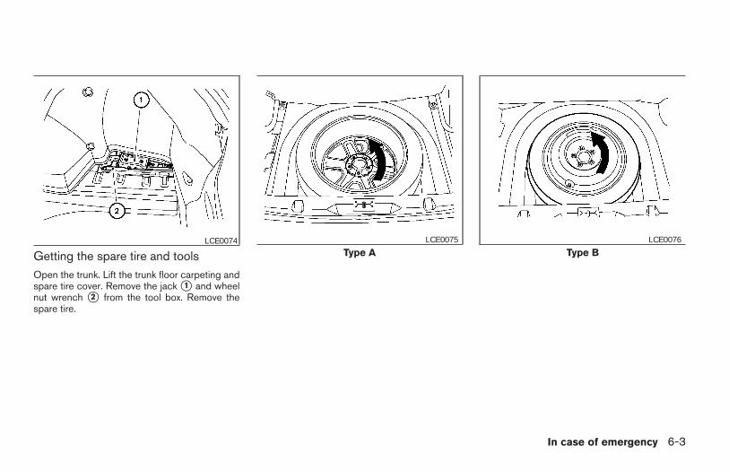
Getting the spare tire and toolsOpen the trunk. Lift the trunk floor carpeting andspare tire cover. Remove the jack s1 and wheelnut wrench s2 from the tool box. Remove thespare tire.
LCE0074Type A
LCE0075
Type BLCE0076
In case of emergency 6-3
Z REVIEW COPY:—2004 Maxima (max)Owners Manual (owners)—USA English (nna)10/07/03—tbrooks X
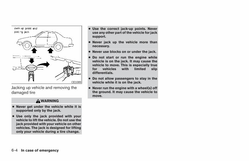
Jacking up vehicle and removing thedamaged tire
WARNING
● Never get under the vehicle while it issupported only by the jack.
● Use only the jack provided with yourvehicle to lift the vehicle. Do not use thejack provided with your vehicle on othervehicles. The jack is designed for liftingonly your vehicle during a tire change.
● Use the correct jack-up points. Neveruse any other part of the vehicle for jacksupport.
● Never jack up the vehicle more thannecessary.
● Never use blocks on or under the jack.
● Do not start or run the engine whilevehicle is on the jack. It may cause thevehicle to move. This is especially truefor vehicles with limited slipdifferentials.
● Do not allow passengers to stay in thevehicle while it is on the jack.
● Never run the engine with a wheel(s) offthe ground. It may cause the vehicle tomove.
CE1089
6-4 In case of emergency
Z REVIEW COPY:—2004 Maxima (max)Owners Manual (owners)—USA English (nna)10/07/03—tbrooks X
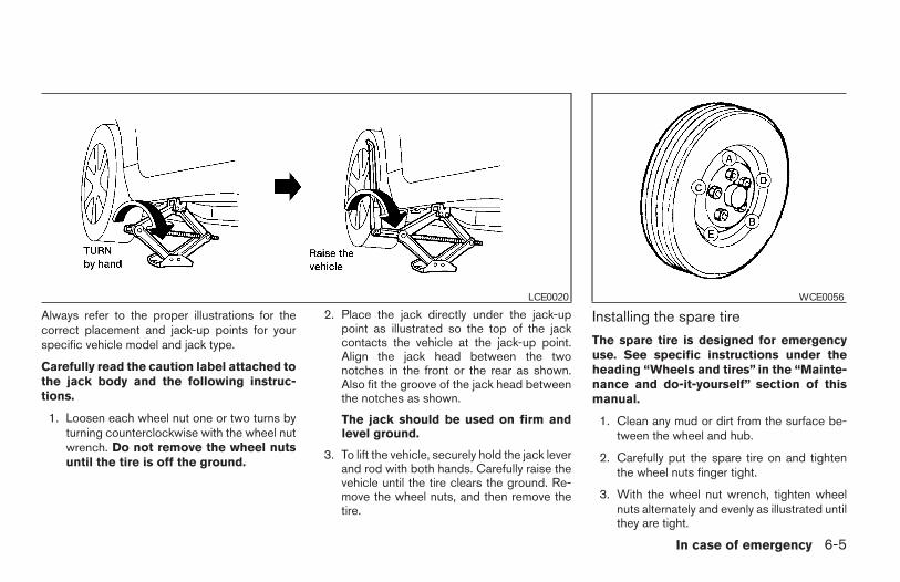
Always refer to the proper illustrations for thecorrect placement and jack-up points for yourspecific vehicle model and jack type.
Carefully read the caution label attached tothe jack body and the following instruc-tions.
1. Loosen each wheel nut one or two turns byturning counterclockwise with the wheel nutwrench. Do not remove the wheel nutsuntil the tire is off the ground.
2. Place the jack directly under the jack-uppoint as illustrated so the top of the jackcontacts the vehicle at the jack-up point.Align the jack head between the twonotches in the front or the rear as shown.Also fit the groove of the jack head betweenthe notches as shown.
The jack should be used on firm andlevel ground.
3. To lift the vehicle, securely hold the jack leverand rod with both hands. Carefully raise thevehicle until the tire clears the ground. Re-move the wheel nuts, and then remove thetire.
Installing the spare tire
The spare tire is designed for emergencyuse. See specific instructions under theheading “Wheels and tires” in the “Mainte-nance and do-it-yourself” section of thismanual.
1. Clean any mud or dirt from the surface be-tween the wheel and hub.
2. Carefully put the spare tire on and tightenthe wheel nuts finger tight.
3. With the wheel nut wrench, tighten wheelnuts alternately and evenly as illustrated untilthey are tight.
LCE0020 WCE0056
In case of emergency 6-5
Z REVIEW COPY:—2004 Maxima (max)Owners Manual (owners)—USA English (nna)10/07/03—tbrooks X
4. Lower the vehicle slowly until the tiretouches the ground. Then, with the wheelnut wrench, tighten the wheel nuts securelyin the sequence illustrated (sA , sB , sC , sD ,sE ). Lower the vehicle completely.
WARNING
● Incorrect wheel nuts or improperlytightened wheel nuts can cause thewheel to become loose or come off.This could cause an accident.
● Do not use oil or grease on the wheelstuds or nuts. This could cause the nutsto become loose.
● Retighten the wheel nuts when the ve-hicle has been driven for 600 miles(1,000 km) (also in cases of a flat tire,etc.).
As soon as possible, tighten the wheel nutsto the specified torque with a torquewrench.
Wheel nut tightening torque:
80 ft-lb (108 N·m)
The wheel nuts must be kept tightened tospecification at all times. It is recom-mended that wheel nuts be tightened tospecifications at each lubrication interval.
Adjust tire pressure to the COLD pressure.
COLD pressure: After vehicle has beenparked for three hours or more or drivenless than 1 mile (1.6 km).
COLD tire pressures are shown on the tireplacard affixed to the center console.
5. Securely store the flat tire and jacking equip-ment in the vehicle.
6. Place the spare tire cover and the trunk floorcarpeting over the damaged tire.
7. Close the trunk.
WARNING
● Always make sure that the spare tireand jacking equipment are properly se-cured after use. Such items can becomedangerous projectiles in an accident orsudden stop.
● The spare tire is designed for emer-gency use. See specific instructions un-der the heading “Wheels and tires” inthe “Maintenance and do-it-yourself”section of this manual.
To start your engine with a booster battery, theinstructions and precautions below must be fol-lowed.
WARNING
● If done incorrectly, jump starting canlead to a battery explosion, resulting insevere injury or death. It could alsodamage your vehicle.
● Explosive hydrogen gas is alwayspresent in the vicinity of the battery.Keep all sparks and flames away fromthe battery.
● Do not allow battery fluid to come intocontact with eyes, skin, clothing orpainted surfaces. Battery fluid is a cor-rosive sulfuric acid solution which cancause severe burns. If the fluid shouldcome into contact with anything, imme-diately flush the contacted area withwater.
● Keep battery out of the reach ofchildren.
● The booster battery must be rated at 12volts. Use of an improperly rated batterycan damage your vehicle.
JUMP STARTING
6-6 In case of emergency
Z REVIEW COPY:—2004 Maxima (max)Owners Manual (owners)—USA English (nna)10/07/03—tbrooks X
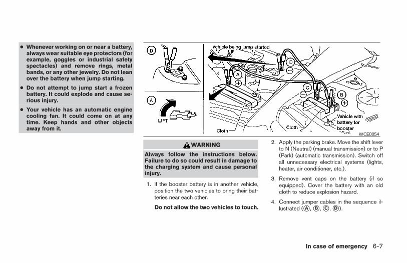
● Whenever working on or near a battery,always wear suitable eye protectors (forexample, goggles or industrial safetyspectacles) and remove rings, metalbands, or any other jewelry. Do not leanover the battery when jump starting.
● Do not attempt to jump start a frozenbattery. It could explode and cause se-rious injury.
● Your vehicle has an automatic enginecooling fan. It could come on at anytime. Keep hands and other objectsaway from it.
WARNING
Always follow the instructions below.Failure to do so could result in damage tothe charging system and cause personalinjury.
1. If the booster battery is in another vehicle,position the two vehicles to bring their bat-teries near each other.
Do not allow the two vehicles to touch.
2. Apply the parking brake. Move the shift leverto N (Neutral) (manual transmission) or to P(Park) (automatic transmission). Switch offall unnecessary electrical systems (lights,heater, air conditioner, etc.).
3. Remove vent caps on the battery (if soequipped). Cover the battery with an oldcloth to reduce explosion hazard.
4. Connect jumper cables in the sequence il-lustrated (sA , sB , sC , sD ).
WCE0054
In case of emergency 6-7
Z REVIEW COPY:—2004 Maxima (max)Owners Manual (owners)—USA English (nna)10/21/03—betty X
CAUTION
● Always connect positive (1) to positive(1) and negative (2) to body ground (forexample, strut mounting bolt, enginelift bracket, etc.) — not to the battery.
● Make sure the jumper cables do nottouch moving parts in the engine com-partment and that the cable clamps donot contact any other metal.
5. Start the engine of the booster vehicle andlet it run for a few minutes.
6. Keep the engine speed of the booster ve-hicle at about 2,000 rpm, and start the en-gine of the vehicle being jump started.
CAUTION
Do not keep the starter motor engaged formore than 10 seconds. If the engine doesnot start right away, turn the key off andwait 3 to 4 seconds before trying again.
7. After starting the engine, carefully discon-nect the negative cable and then the positivecable.
8. Replace the vent caps (if so equipped). Besure to dispose of the cloth used to coverthe vent holes as it may be contaminatedwith corrosive acid.
WARNING
● Automatic transmission models cannotbe push-started or tow-started. Thismay cause transmission or other ve-hicle damage.
● Three-way catalyst equipped modelsshould not be started by pushing. Thethree-way catalyst may be damaged.
● Never try to start the vehicle by towingit. When the engine starts, the forwardsurge could cause the vehicle to collidewith the tow vehicle.
PUSH STARTING
6-8 In case of emergency
Z REVIEW COPY:—2004 Maxima (max)Owners Manual (owners)—USA English (nna)10/07/03—tbrooks X
If your vehicle is overheating (indicated by anextremely high temperature gauge reading), or ifyou feel a lack of engine power, detect abnormalnoise, etc. take the following steps.
WARNING
● Do not continue to drive if your vehicleoverheats. Doing so could cause enginedamage or a vehicle fire.
● To avoid the danger of being scalded,never remove the radiator cap while theengine is still hot. When the radiatorcap is removed, pressurized hot waterwill spurt out, possibly causing seriousinjury.
● Do not open the hood if steam is com-ing out.
1. Move the vehicle safely off the road, applythe parking brake and move the shift lever toN (Neutral) (manual transmission) or to P(Park) (automatic transmission).
Do not stop the engine.
2. Turn off the air conditioner (if so equipped).Open all the windows, move the heater or airconditioner temperature control to maximumhot and fan control to high speed.
3. Get out of the vehicle. Look and listen forsteam or coolant escaping from the radiatorbefore opening the hood. (If steam or cool-ant is escaping, turn off the engine.) Do notopen the hood further until no steam orcoolant can be seen.
4. Open the engine hood.
WARNING
If steam or water is coming from the en-gine, stand clear to prevent gettingburned.
5. Visually check drive belts for damage orlooseness. Also check if the cooling fan isrunning. The radiator hoses and radiatorshould not leak water. If coolant is leaking,the water pump belt is missing or loose, orthe cooling fan does not run, stop the en-gine.
WARNING
Be careful not to allow your hands, hair,jewelry or clothing to come into contactwith, or get caught in, engine belts or theengine cooling fan. The engine coolingfan can start at any time when the coolanttemperature is high.
6. After the engine cools down, check the cool-ant level in the reservoir tank with the enginerunning. Add coolant to the reservoir tank ifnecessary. Have your vehicle repaired at aNISSAN dealer.
IF YOUR VEHICLE OVERHEATS
In case of emergency 6-9
Z REVIEW COPY:—2004 Maxima (max)Owners Manual (owners)—USA English (nna)10/07/03—tbrooks X
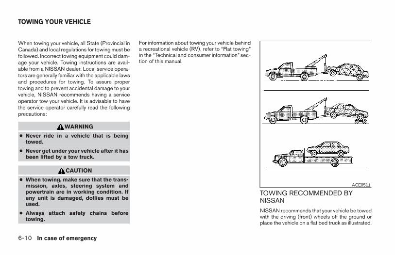
When towing your vehicle, all State (Provincial inCanada) and local regulations for towing must befollowed. Incorrect towing equipment could dam-age your vehicle. Towing instructions are avail-able from a NISSAN dealer. Local service opera-tors are generally familiar with the applicable lawsand procedures for towing. To assure propertowing and to prevent accidental damage to yourvehicle, NISSAN recommends having a serviceoperator tow your vehicle. It is advisable to havethe service operator carefully read the followingprecautions:
WARNING
● Never ride in a vehicle that is beingtowed.
● Never get under your vehicle after it hasbeen lifted by a tow truck.
CAUTION
● When towing, make sure that the trans-mission, axles, steering system andpowertrain are in working condition. Ifany unit is damaged, dollies must beused.
● Always attach safety chains beforetowing.
For information about towing your vehicle behinda recreational vehicle (RV), refer to “Flat towing”in the “Technical and consumer information” sec-tion of this manual.
TOWING RECOMMENDED BYNISSANNISSAN recommends that your vehicle be towedwith the driving (front) wheels off the ground orplace the vehicle on a flat bed truck as illustrated.
ACE0511
TOWING YOUR VEHICLE
6-10 In case of emergency
Z REVIEW COPY:—2004 Maxima (max)Owners Manual (owners)—USA English (nna)10/07/03—tbrooks X
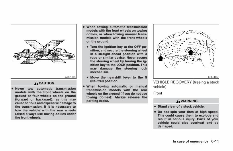
CAUTION
● Never tow automatic transmissionmodels with the front wheels on theground or four wheels on the ground(forward or backward), as this maycause serious and expensive damage tothe transmission. If it is necessary totow the vehicle with the rear wheelsraised always use towing dollies underthe front wheels.
● When towing automatic transmissionmodels with the front wheels on towingdollies, or when towing manual trans-mission models with the front wheelson the ground:
● Turn the ignition key to the OFF po-sition, and secure the steering wheelin a straight-ahead position with arope or similar device. Never securethe steering wheel by turning the ig-nition key to the LOCK position. Thismay damage the steering lockmechanism.
● Move the gearshift lever to the N(Neutral) position.
● When towing automatic or manualtransmission models with the rearwheels on the ground (if you do not usetowing dollies): Always release theparking brake.
VEHICLE RECOVERY (freeing a stuckvehicle)
Front
WARNING
● Stand clear of a stuck vehicle.
● Do not spin your tires at high speed.This could cause them to explode andresult in serious injury. Parts of yourvehicle could also overheat and bedamaged.
ACE1001 LCE0077
In case of emergency 6-11
Z REVIEW COPY:—2004 Maxima (max)Owners Manual (owners)—USA English (nna)10/07/03—tbrooks X
CAUTION
● Use the towing hook only, not otherparts of the vehicle. Otherwise, the ve-hicle body will be damaged.
● Use the towing hook only to free a ve-hicle stuck in sand, snow, mud, etc.Never tow the vehicle for a long dis-tance using only the towing hook.
● The towing hook is under tremendousforce when used to free a stuck vehicle.Always pull the cable straight out fromthe front or rear of the vehicle. Neverpull the hook at an angle.
● Pulling devices should be routed sothey do not touch any part of the sus-pension, steering, brake or coolingsystems.
● Pull devices such as ropes or canvasstraps are not recommended for use invehicle towing or recovery.
Rear
WARNING
● Stand clear of a stuck vehicle.
● Do not spin your tires at high speed.This could cause them to explode andresult in serious injury. Parts of yourvehicle could also overheat and bedamaged.
CAUTION
● Tow chains or cables must be attachedonly to the main structural members ofthe vehicle.
● Pulling devices should be routed sothey do not touch any part of the sus-pension, steering, brake or coolingsystems.
● Always pull the cable straight out fromthe front or rear of the vehicle. Neverpull the vehicle at an angle.
● Pull devices such as ropes or canvasstraps are not recommended for use invehicle towing or recovery.
6-12 In case of emergency
Z REVIEW COPY:—2004 Maxima (max)Owners Manual (owners)—USA English (nna)10/07/03—tbrooks X
7 Appearance and care
Cleaning exterior . . . . . . . . . . . . . . . . . . . . . . . . . . . . . . . . . . 7-2Washing . . . . . . . . . . . . . . . . . . . . . . . . . . . . . . . . . . . . . . 7-2Waxing . . . . . . . . . . . . . . . . . . . . . . . . . . . . . . . . . . . . . . . . 7-2Removing spots . . . . . . . . . . . . . . . . . . . . . . . . . . . . . . . . 7-2Underbody . . . . . . . . . . . . . . . . . . . . . . . . . . . . . . . . . . . . 7-3Glass . . . . . . . . . . . . . . . . . . . . . . . . . . . . . . . . . . . . . . . . . 7-3Aluminum alloy wheels . . . . . . . . . . . . . . . . . . . . . . . . . . 7-3Chrome parts . . . . . . . . . . . . . . . . . . . . . . . . . . . . . . . . . . 7-3
Cleaning interior. . . . . . . . . . . . . . . . . . . . . . . . . . . . . . . . . . . 7-4
Floor mats . . . . . . . . . . . . . . . . . . . . . . . . . . . . . . . . . . . . . 7-4Seat belts . . . . . . . . . . . . . . . . . . . . . . . . . . . . . . . . . . . . . 7-5
Corrosion protection . . . . . . . . . . . . . . . . . . . . . . . . . . . . . . . 7-5Most common factors contributing to vehiclecorrosion . . . . . . . . . . . . . . . . . . . . . . . . . . . . . . . . . . . . . . 7-5Environmental factors influence the rate ofcorrosion . . . . . . . . . . . . . . . . . . . . . . . . . . . . . . . . . . . . . . 7-5To protect your vehicle from corrosion . . . . . . . . . . . . 7-5
Z REVIEW COPY:—2004 Maxima (max)Owners Manual (owners)—USA English (nna)10/20/03—arosenma X
In order to maintain the appearance of your ve-hicle, it is important to take proper care of it.
To protect the paint surfaces, please wash yourvehicle as soon as you can:
● after a rainfall to prevent possible damagefrom acid rain.
● after driving on coastal roads.
● when contaminants such as soot, bird drop-pings, tree sap, metal particles or bugs geton the paint surface.
● when dust or mud builds up on the surface.
Whenever possible, store or park your vehicleinside a garage or in a covered area.
When it is necessary to park outside, park in ashady area or protect the vehicle with a bodycover.
Be careful not to scratch the paint surfacewhen putting on or removing the bodycover.
WASHINGWash dirt off with a wet sponge and plenty ofwater. Clean the vehicle thoroughly using a mildsoap, a special vehicle soap or general purposedishwashing liquid mixed with clean, lukewarm(never hot) water.
CAUTION
● Do not wash the vehicle with stronghousehold soap, strong chemical deter-gents, gasoline or solvents.
● Do not wash the vehicle in direct sun-light or while the vehicle body is hot, asthe surface may become water-spotted.
● Avoid using tight-napped or roughcloths, such as washing mitts. Caremust be taken when removingcaked-on dirt or other foreign sub-stances so the paint surface is notscratched or damaged.
Rinse the vehicle thoroughly with plenty of cleanwater.
Inside flanges, seams and folds on the doors,hatches and hood are particularly vulnerable tothe effects of road salt. Therefore, these areasmust be cleaned regularly. Take care that thedrain holes in the lower edge of the door areopen. Spray water under the body and in thewheel wells to loosen the dirt and wash awayroad salt.
A damp chamois can be used to dry the vehicle toavoid water spots.
WAXING
Regular waxing protects the paint surface andhelps retain new vehicle appearance. After wax-ing, polishing is recommended to removebuilt-up residue and to avoid a “weathered” ap-pearance.
A NISSAN dealer can assist you in choosing theproper product.
● Wax your vehicle only after a thorough wash-ing. Follow the instructions supplied with thewax.
● Do not use a wax containing any abrasives,cutting compounds or cleaners that maydamage the vehicle finish.
● If the surface does not polish easily, use a“road tar” remover and wax again.
Machine compounding or aggressive polishingon a base coat/clear coat paint finish may dull thefinish or leave swirl marks.
REMOVING SPOTSRemove tar and oil spots, industrial dust, insects,and tree sap as quickly as possible from thesurface of the paint to avoid lasting damage orstaining. Special cleaning products are availableat a NISSAN dealer or any automotive accessorystore.
CLEANING EXTERIOR
7-2 Appearance and care
Z REVIEW COPY:—2004 Maxima (max)Owners Manual (owners)—USA English (nna)10/07/03—tbrooks X
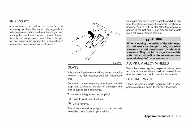
UNDERBODYIn areas where road salt is used in winter, it isnecessary to clean the underbody regularly inorder to prevent dirt and salt from building up andcausing the acceleration of corrosion on the un-derbody and suspension. Before the winter pe-riod and again in the spring, the underseal mustbe checked and, if necessary, retreated.
GLASS
When cleaning the rear window, it may be easierto clean if the high-mounted stop light is removedfirst.
Be careful when removing the high-mountedstop light to reduce the risk of damaging thehigh-mounted stop light wires.
To remove the high-mounted stop light:
s1 Push toward rear of vehicle.
s2 Lift to remove.
The high-mounted stop light must be properlyreinstalled before driving your vehicle.
Use glass cleaner to remove smoke and dust filmfrom the glass surfaces. It is normal for glass tobecome coated with a film after the vehicle isparked in the hot sun. Glass cleaner and a softcloth will easily remove this film.
CAUTION
When cleaning the inside of the windows,do not use sharp-edged tools, abrasivecleaners or chlorine-based disinfectantcleaners. They could damage the electri-cal conductors, radio antenna elements orrear window defroster elements.
ALUMINUM ALLOY WHEELSWash the wheels regularly, especially during win-ter months in areas where road salt is used. If notremoved, road salt could discolor the wheels.
CHROME PARTSClean all chrome parts regularly with a non-abrasive chrome polish to maintain the finish.
LAI0008
Appearance and care 7-3
Z REVIEW COPY:—2004 Maxima (max)Owners Manual (owners)—USA English (nna)10/07/03—tbrooks X
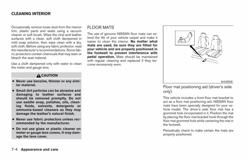
Occasionally remove loose dust from the interiortrim, plastic parts and seats using a vacuumcleaner or soft brush. Wipe the vinyl and leathersurfaces with a clean, soft cloth dampened inmild soap solution, then wipe clean with a dry,soft cloth. Before using any fabric protector, readthe manufacturer’s recommendations. Some fab-ric protectors contain chemicals that may stain orbleach the seat material.
Use a cloth dampened only with water to cleanthe meter and gauge lens.
CAUTION
● Never use benzine, thinner or any simi-lar material.
● Small dirt particles can be abrasive anddamaging to leather surfaces andshould be removed promptly. Do notuse saddle soap, polishes, oils, clean-ing fluids, solvents, detergents orammonia-based cleaners as they maydamage the leather’s natural finish.
● Never use fabric protectors unless rec-ommended by the manufacturer.
● Do not use glass or plastic cleaner onmeter or gauge lens covers. It may dam-age the lens cover.
FLOOR MATSThe use of genuine NISSAN floor mats can ex-tend the life of your vehicle carpet and make iteasier to clean the interior. No matter whatmats are used, be sure they are fitted foryour vehicle and are properly positioned inthe footwell to prevent interference withpedal operation. Mats should be maintainedwith regular cleaning and replaced if they be-come excessively worn.
Floor mat positioning aid (driver’s sideonly)This vehicle includes a front floor mat bracket toact as a floor mat positioning aid. NISSAN floormats have been specially designed for your ve-hicle model. The driver’s side floor mat has agrommet hole incorporated in it. Position the matby placing the floor mat bracket hook through thefloor mat grommet hole while centering the mat inthe footwell.
Periodically check to make certain the mats areproperly positioned.
WAI0006
CLEANING INTERIOR
7-4 Appearance and care
Z REVIEW COPY:—2004 Maxima (max)Owners Manual (owners)—USA English (nna)10/07/03—tbrooks X
SEAT BELTSThe seat belts can be cleaned by wiping themwith a sponge dampened in a mild soap solution.Allow the belts to dry completely in the shadebefore using them. See “Seat belt maintenance”in the “Safety – Seats, seat belts and supplemen-tal air bags” section of this manual.
WARNING
Do not allow wet seat belts to roll up in theretractor. NEVER use bleach, dye orchemical solvents to clean the seat belts,since these materials may severelyweaken the seat belt webbing.
MOST COMMON FACTORSCONTRIBUTING TO VEHICLECORROSION
1. The accumulation of moisture-retaining dirtand debris in body panel sections, cavities,and other areas.
2. Damage to paint and other protective coat-ings caused by gravel and stone chips orminor traffic accidents.
ENVIRONMENTAL FACTORSINFLUENCE THE RATE OFCORROSION
MoistureAccumulation of sand, dirt and water on the ve-hicle body underside can accelerate corrosion.Wet floor coverings will not dry completely insidethe vehicle, and should be removed for drying toavoid floor panel corrosion.
Relative humidityCorrosion will be accelerated:
● in areas of high relative humidity.
● in areas where the temperatures stay abovefreezing.
● where atmospheric pollution exists.
● where road salt is used.Temperature
High temperatures accelerate the rate of corro-sion to those parts which are not well ventilated.
Air pollution
Industrial pollution, the presence of salt in the airin coastal areas, or heavy road salt use acceler-ates the corrosion process. Road salt also accel-erates the disintegration of paint surfaces.
TO PROTECT YOUR VEHICLEFROM CORROSION
● Wash and wax your vehicle often to keep thevehicle clean.
● Always check for minor damage to the paintand repair it as soon as possible.
● Keep drain holes at the bottom of the doorsopen to avoid water accumulation.
● Check the underbody for accumulation ofsand, dirt or salt. If present, wash with wateras soon as possible.
CORROSION PROTECTION
Appearance and care 7-5
Z REVIEW COPY:—2004 Maxima (max)Owners Manual (owners)—USA English (nna)10/20/03—arosenma X
CAUTION
● NEVER remove dirt, sand or other de-bris from the passenger compartmentby washing it out with a hose. Removedirt with a vacuum cleaner or broom.
● Never allow water or other liquids tocome in contact with electronic compo-nents inside the vehicle as this maydamage them.
Chemicals used for road surface de-icing areextremely corrosive. They accelerate corrosionand deterioration of underbody componentssuch as the exhaust system, fuel and brake lines,brake cables, floor pan and fenders.
In winter, the underbody must be cleanedperiodically.
For additional protection against rust and corro-sion, which may be required in some areas, con-sult a NISSAN dealer.
7-6 Appearance and care
Z REVIEW COPY:—2004 Maxima (max)Owners Manual (owners)—USA English (nna)10/20/03—arosenma X
8 Maintenance and do-it-yourself
Maintenance requirements. . . . . . . . . . . . . . . . . . . . . . . . . . 8-2General maintenance . . . . . . . . . . . . . . . . . . . . . . . . . . . . . . 8-2
Explanation of general maintenance items . . . . . . . . . 8-2Maintenance precautions . . . . . . . . . . . . . . . . . . . . . . . . . . . 8-5Engine compartment check locations . . . . . . . . . . . . . . . . 8-6Engine cooling system . . . . . . . . . . . . . . . . . . . . . . . . . . . . . 8-7
Checking engine coolant level . . . . . . . . . . . . . . . . . . . 8-7Changing engine coolant . . . . . . . . . . . . . . . . . . . . . . . . 8-8
Engine oil. . . . . . . . . . . . . . . . . . . . . . . . . . . . . . . . . . . . . . . . . 8-8Checking engine oil level . . . . . . . . . . . . . . . . . . . . . . . . 8-8Changing engine oil . . . . . . . . . . . . . . . . . . . . . . . . . . . . 8-9Changing engine oil filter . . . . . . . . . . . . . . . . . . . . . . . 8-10
4-speed automatic transmission fluid . . . . . . . . . . . . . . . 8-11Temperature conditions for checking. . . . . . . . . . . . . 8-11
5-speed automatic transmission fluid . . . . . . . . . . . . . . . 8-12Power steering fluid. . . . . . . . . . . . . . . . . . . . . . . . . . . . . . .8-13Brake and clutch fluid . . . . . . . . . . . . . . . . . . . . . . . . . . . . .8-13
Brake fluid . . . . . . . . . . . . . . . . . . . . . . . . . . . . . . . . . . . .8-13Clutch fluid . . . . . . . . . . . . . . . . . . . . . . . . . . . . . . . . . . .8-14
Window washer fluid . . . . . . . . . . . . . . . . . . . . . . . . . . . . .8-14Window washer fluid reservoir . . . . . . . . . . . . . . . . . . 8-14
Battery . . . . . . . . . . . . . . . . . . . . . . . . . . . . . . . . . . . . . . . . . .8-15Jump starting . . . . . . . . . . . . . . . . . . . . . . . . . . . . . . . . .8-16
Drive belts . . . . . . . . . . . . . . . . . . . . . . . . . . . . . . . . . . . . . . .8-17
Spark plugs. . . . . . . . . . . . . . . . . . . . . . . . . . . . . . . . . . . . . .8-17Replacing spark plugs . . . . . . . . . . . . . . . . . . . . . . . . . 8-17
Air cleaner . . . . . . . . . . . . . . . . . . . . . . . . . . . . . . . . . . . . . . .8-18In-cabin microfilter . . . . . . . . . . . . . . . . . . . . . . . . . . . . .8-18
Windshield wiper blades . . . . . . . . . . . . . . . . . . . . . . . . . . 8-21Cleaning . . . . . . . . . . . . . . . . . . . . . . . . . . . . . . . . . . . . .8-21Replacing . . . . . . . . . . . . . . . . . . . . . . . . . . . . . . . . . . . .8-21
Parking brake and brake pedal . . . . . . . . . . . . . . . . . . . . . 8-22Checking parking brake . . . . . . . . . . . . . . . . . . . . . . . . 8-22Checking brake pedal. . . . . . . . . . . . . . . . . . . . . . . . . . 8-22Brake booster . . . . . . . . . . . . . . . . . . . . . . . . . . . . . . . . .8-23
Fuses . . . . . . . . . . . . . . . . . . . . . . . . . . . . . . . . . . . . . . . . . . .8-23Engine compartment . . . . . . . . . . . . . . . . . . . . . . . . . . . 8-23Passenger compartment . . . . . . . . . . . . . . . . . . . . . . . 8-25
Keyfob battery replacement . . . . . . . . . . . . . . . . . . . . . . . . 8-26Lights . . . . . . . . . . . . . . . . . . . . . . . . . . . . . . . . . . . . . . . . . . .8-27
Headlights . . . . . . . . . . . . . . . . . . . . . . . . . . . . . . . . . . . .8-27Exterior and interior lights. . . . . . . . . . . . . . . . . . . . . . . 8-28
Wheels and tires . . . . . . . . . . . . . . . . . . . . . . . . . . . . . . . . .8-33Tire pressure. . . . . . . . . . . . . . . . . . . . . . . . . . . . . . . . . .8-33Tire labeling. . . . . . . . . . . . . . . . . . . . . . . . . . . . . . . . . . .8-36Types of tires. . . . . . . . . . . . . . . . . . . . . . . . . . . . . . . . . .8-39Tire chains. . . . . . . . . . . . . . . . . . . . . . . . . . . . . . . . . . . .8-39Changing wheels and tires . . . . . . . . . . . . . . . . . . . . . 8-40
Z REVIEW COPY:—2004 Maxima (max)Owners Manual (owners)—USA English (nna)10/20/03—arosenma X
Your new NISSAN has been designed to haveminimum maintenance requirements with longerservice intervals to save you both time andmoney. However, some day-to-day and regularmaintenance is essential to maintain your NIS-SAN’s good mechanical condition, as well as itsemission and engine performance.
It is the owner’s responsibility to make sure thatthe scheduled maintenance, as well as generalmaintenance, is performed.
As the vehicle owner, you are the only one whocan ensure that your vehicle receives propermaintenance. You are a vital link in the mainte-nance chain.
Scheduled maintenance
For your convenience, both required and optionalscheduled maintenance items are described andlisted in your “NISSAN Service and MaintenanceGuide.” You must refer to that guide to ensurethat necessary maintenance is performed on yourNISSAN at regular intervals.
General maintenance
General maintenance includes those items whichshould be checked during normal day-to-day op-eration. They are essential for proper vehicle op-eration. It is your responsibility to perform thesemaintenance procedures regularly as prescribed.
Performing general maintenance checks requiresminimal mechanical skill and only a few generalautomotive tools.
These checks or inspections can be done by you,a qualified technician, or, if you prefer, a NISSANdealer.
Where to go for service
If maintenance service is required or your vehicleappears to malfunction, have the systemschecked and corrected by a NISSAN dealer.
NISSAN technicians are well-trained specialistswho are kept up-to-date with the latest serviceinformation through technical bulletins, servicetips, and in-dealership training programs. Theyare completely qualified to work on NISSAN ve-hicles before they work on your vehicle, ratherthan after they have worked on it.
You can be confident that a NISSAN dealer’sservice department performs the best job to meetthe maintenance requirements on your vehicle —in a reliable and economic way.
During the normal day-to-day operation of thevehicle, general maintenance should be per-formed regularly as prescribed in this section. Ifyou detect any unusual sounds, vibrations orsmells, be sure to check for the cause or have aNISSAN dealer do it promptly. In addition, youshould notify a NISSAN dealer if you think thatrepairs are required.
When performing any checks or maintenancework, closely observe the “Maintenance precau-tions” later in this section.
EXPLANATION OF GENERALMAINTENANCE ITEMS
Additional information on the followingitems with “*” is found later in this section.
Outside the vehicle
The maintenance items listed here should beperformed from time to time, unless otherwisespecified.
Doors and engine hood Check that the doorsand engine hood operate properly. Also ensurethat all latches lock securely. Lubricate hinges,latches, latch pins, rollers and links as necessary.Make sure that the secondary latch keeps thehood from opening when the primary latch isreleased.
MAINTENANCE REQUIREMENTS GENERAL MAINTENANCE
8-2 Maintenance and do-it-yourself
Z REVIEW COPY:—2004 Maxima (max)Owners Manual (owners)—USA English (nna)10/20/03—arosenma X
When driving in areas using road salt or othercorrosive materials, check lubrication frequently.
Lights* Clean the headlights on a regular basis.Make sure that the headlights, stop lights, taillights, turn signal lights, and other lights are alloperating properly and installed securely. Alsocheck headlight aim.
Road wheel nuts* When checking the tires,make sure no wheel nuts are missing, and checkfor any loose wheel nuts. Tighten if necessary.
Tire rotation* Tires should be rotated every7,500 miles (12,000 km).
Tires* Check the pressure with a gauge oftenand always prior to long distance trips. If neces-sary, adjust the pressure in all tires, including thespare, to the pressure specified. Check carefullyfor damage, cuts or excessive wear.
Wheel alignment and balance If the vehicleshould pull to either side while driving on astraight and level road, or if you detect uneven orabnormal tire wear, there may be a need for wheelalignment. If the steering wheel or seat vibrates atnormal highway speeds, wheel balancing may beneeded.
● For additional information regarding tires,refer to “Important Tire Safety Information”(US) or “Tire Safety Information” (Canada) inthe Warranty Information Booklet .
Windshield Clean the windshield on a regularbasis. Check the windshield at least every sixmonths for cracks or other damage. Have a dam-aged windshield repaired by a qualified repairfacility.
Windshield wiper blades* Check for cracks orwear if they do not wipe properly.
Inside the vehicle
The maintenance items listed here should bechecked on a regular basis, such as when per-forming periodic maintenance, cleaning the ve-hicle, etc.
Additional information on the followingitems with an “*” is found later in this sec-tion.
Accelerator pedal Check the pedal for smoothoperation and make sure the pedal does not bindor require uneven effort. Keep the floor mat awayfrom the pedal.
Automatic transmission P (Park) positionmechanism On a fairly steep hill check that yourvehicle is held securely with the selector lever inthe P position without applying any brakes.
Brake pedal and booster* Check the pedal forsmooth operation and make sure it has the properdistance under it when depressed fully. Check
the brake booster function. Be certain to keep thefloor mat away from the pedal.
Brakes Check that the brakes do not pull thevehicle to one side when applied.
Clutch pedal* Make sure the pedal operatessmoothly and check that it has the proper freetravel.
Parking brake* Check that the lever has theproper travel and confirm that your vehicle is heldsecurely on a fairly steep hill with only the parkingbrake applied.
Seats Check seat position controls such as seatadjusters, seatback recliner, etc. to ensure theyoperate smoothly and all latches lock securely inevery position. Check that the head restraintsmove up and down smoothly and the locks (if soequipped) hold securely in all latched positions.
Seat belts Check that all parts of the seat beltsystem (for example, buckles, anchors, adjustersand retractors) operate properly and smoothly,and are installed securely. Check the belt web-bing for cuts, fraying, wear or damage.
Steering wheel Check for changes in the steer-ing system, such as excessive freeplay, hardsteering or strange noises.
Warning lights and chimes Make sure allwarning lights and chimes are operating properly.
Maintenance and do-it-yourself 8-3
Z REVIEW COPY:—2004 Maxima (max)Owners Manual (owners)—USA English (nna)10/20/03—arosenma X
Windshield wiper and washer* Check thatthe wipers and washer operate properly and thatthe wipers do not streak.
Windshield defroster Check that the aircomes out of the defroster outlets properly and insufficient quantity when operating the heater orair conditioner.
Under the hood and vehicle
The maintenance items listed here should bechecked periodically (for example, each time youcheck the engine oil or refuel).
Automatic transmission fluid level* Checkthe level after putting the selector lever in P withthe engine idling at operating temperature.
Battery* Check the fluid level in each cell. Itshould be between the MAX and MIN lines. Ve-hicles operated in high temperatures or undersevere conditions require frequent checks of thebattery fluid level.
Brake and clutch fluid levels* Make sure thatthe brake and clutch fluid level is between theMIN and MAX lines on the reservoir.
Engine coolant level* Check the coolant levelwhen the engine is cold.
Engine drive belts* Make sure the drive beltsare not frayed, worn, cracked or oily.
Engine oil level* Check the level after parkingthe vehicle on a level surface with the engine off.Wait more than 10 minutes for the oil to drainback into the oil pan.
Exhaust system Make sure there are no loosesupports, cracks or holes. If the sound of theexhaust seems unusual or there is a smell ofexhaust fumes, immediately have the exhaustsystem inspected by a NISSAN dealer. See thecarbon monoxide warning in the “Starting anddriving” section of this manual.
Fluid leaks Check under the vehicle for fuel, oil,water or other fluid leaks after the vehicle hasbeen parked for a while. Water dripping from theair conditioner after use is normal. If you shouldnotice any leaks or if gasoline fumes are evident,check for the cause and have it corrected imme-diately.
Power steering fluid level* and lines Checkthe level when the fluid is cold, with the engineoff. Check the lines for proper attachment, leaks,cracks, etc.
Radiator and hoses Check the front of theradiator and clean off any dirt, insects, leaves,etc., that may have accumulated. Make sure thehoses have no cracks, deformation, rot or looseconnections.
Underbody The underbody is frequently ex-posed to corrosive substances such as thoseused on icy roads or to control dust. It is veryimportant to remove these substances from theunderbody, otherwise rust may form on the floorpan, frame, fuel lines and exhaust system. At theend of winter, the underbody should be thor-oughly flushed with plain water, in those areaswhere mud and dirt may have accumulated. Seethe “Appearance and care” section of thismanual.
Windshield washer fluid* Check that there isadequate fluid in the reservoir.
8-4 Maintenance and do-it-yourself
Z REVIEW COPY:—2004 Maxima (max)Owners Manual (owners)—USA English (nna)10/20/03—arosenma X
When performing any inspection or maintenancework on your vehicle, always take care to preventserious accidental injury to yourself or damage tothe vehicle. The following are general precau-tions which should be closely observed.
WARNING
● Park the vehicle on a level surface, ap-ply the parking brake securely andblock the wheels to prevent the vehiclefrom moving. For manual transmissionmodels, move the shift lever to N (Neu-tral). For automatic transmission mod-els, move the selector lever to P (Park).
● Be sure the ignition key is in the OFF orLOCK position when performing anyparts replacement or repairs.
● Never leave the engine or automatictransmission related component har-nesses disconnected while the ignitionswitch is in the ON position.
● Never connect or disconnect the batteryor any transistorized component whilethe ignition switch is in the ON position.
● Your vehicle is equipped with an auto-matic engine cooling fan. It may come onat any time without warning, even if the
ignition key is in the OFF position and theengine is not running. To avoid injury,always disconnect the negative batterycable before working near the fan.
● If you must work with the engine run-ning, keep your hands, clothing, hairand tools away from moving fans, beltsand any other moving parts.
● It is advisable to secure or remove anyloose clothing and remove any jewelry,such as rings, watches, etc. beforeworking on your vehicle.
● Always wear eye protection wheneveryou work on your vehicle.
● If you must run the engine in an en-closed space such as a garage, be surethere is proper ventilation for exhaustgases to escape.
● Never get under the vehicle while it issupported only by a jack. If it is neces-sary to work under the vehicle, supportit with safety stands.
● Keep smoking materials, flame andsparks away from the fuel tank andbattery.
● On gasoline engine models with themultiport fuel injection (MFI) system,
the fuel filter or fuel lines should beserviced by a NISSAN dealer becausethe fuel lines are under high pressureeven when the engine is off.
CAUTION
● Do not work under the hood while theengine is hot. Turn the engine off andwait until it cools down.
● Avoid contact with used engine oil andcoolant. Improperly disposed engineoil, engine coolant and/or other vehiclefluids can damage the environment. Al-ways conform to local regulations fordisposal of vehicle fluid.
This “Maintenance and do-it-yourself” sectiongives instructions regarding only those itemswhich are relatively easy for an owner to perform.
A genuine NISSAN service manual is also avail-able. See “Owner’s Manual/Service Manual or-der information” in the “Technical and consumerinformation” section of this manual.
You should be aware that incomplete or improperservicing may result in operating difficulties orexcessive emissions, and could affect warrantycoverage. If in doubt about any servicing,have it done by a NISSAN dealer.
MAINTENANCE PRECAUTIONS
Maintenance and do-it-yourself 8-5
Z REVIEW COPY:—2004 Maxima (max)Owners Manual (owners)—USA English (nna)10/20/03—arosenma X
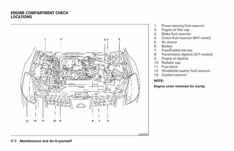
1. Power steering fluid reservoir2. Engine oil filler cap3. Brake fluid reservoir4. Clutch fluid reservoir (M/T model)5. Air cleaner6. Battery7. Fuse/Fusible link box8. Transmission dipstick (A/T models)9. Engine oil dipstick10. Radiator cap11. Fuse block12. Windshield washer fluid reservoir13. Coolant reservoir
NOTE:
Engine cover removed for clarity.
LDI0330
ENGINE COMPARTMENT CHECKLOCATIONS
8-6 Maintenance and do-it-yourself
Z REVIEW COPY:—2004 Maxima (max)Owners Manual (owners)—USA English (nna)10/20/03—arosenma X
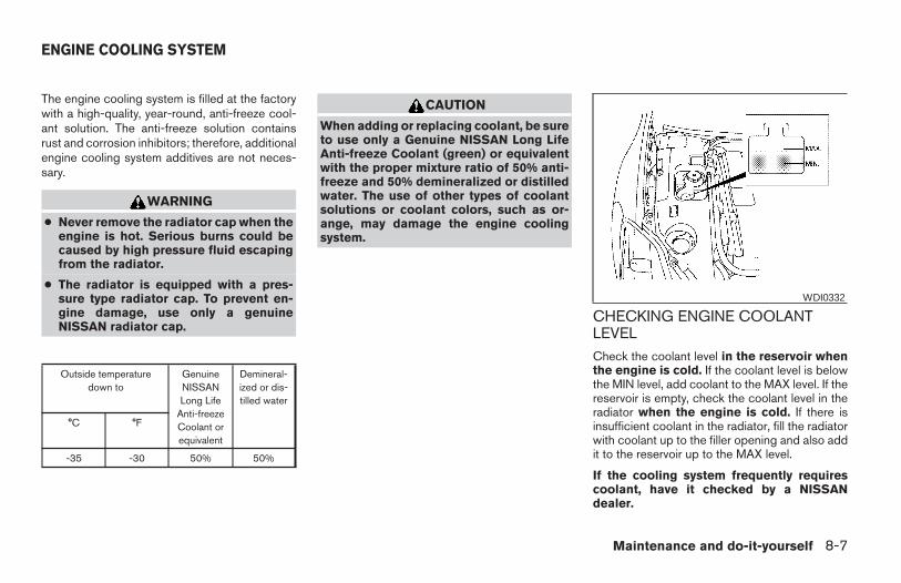
The engine cooling system is filled at the factorywith a high-quality, year-round, anti-freeze cool-ant solution. The anti-freeze solution containsrust and corrosion inhibitors; therefore, additionalengine cooling system additives are not neces-sary.
WARNING
● Never remove the radiator cap when theengine is hot. Serious burns could becaused by high pressure fluid escapingfrom the radiator.
● The radiator is equipped with a pres-sure type radiator cap. To prevent en-gine damage, use only a genuineNISSAN radiator cap.
Outside temperaturedown to
GenuineNISSANLong Life
Anti-freezeCoolant orequivalent
Demineral-ized or dis-tilled water
°C °F
-35 -30 50% 50%
CAUTION
When adding or replacing coolant, be sureto use only a Genuine NISSAN Long LifeAnti-freeze Coolant (green) or equivalentwith the proper mixture ratio of 50% anti-freeze and 50% demineralized or distilledwater. The use of other types of coolantsolutions or coolant colors, such as or-ange, may damage the engine coolingsystem.
CHECKING ENGINE COOLANTLEVELCheck the coolant level in the reservoir whenthe engine is cold. If the coolant level is belowthe MIN level, add coolant to the MAX level. If thereservoir is empty, check the coolant level in theradiator when the engine is cold. If there isinsufficient coolant in the radiator, fill the radiatorwith coolant up to the filler opening and also addit to the reservoir up to the MAX level.
If the cooling system frequently requirescoolant, have it checked by a NISSANdealer.
WDI0332
ENGINE COOLING SYSTEM
Maintenance and do-it-yourself 8-7
Z REVIEW COPY:—2004 Maxima (max)Owners Manual (owners)—USA English (nna)10/20/03—arosenma X
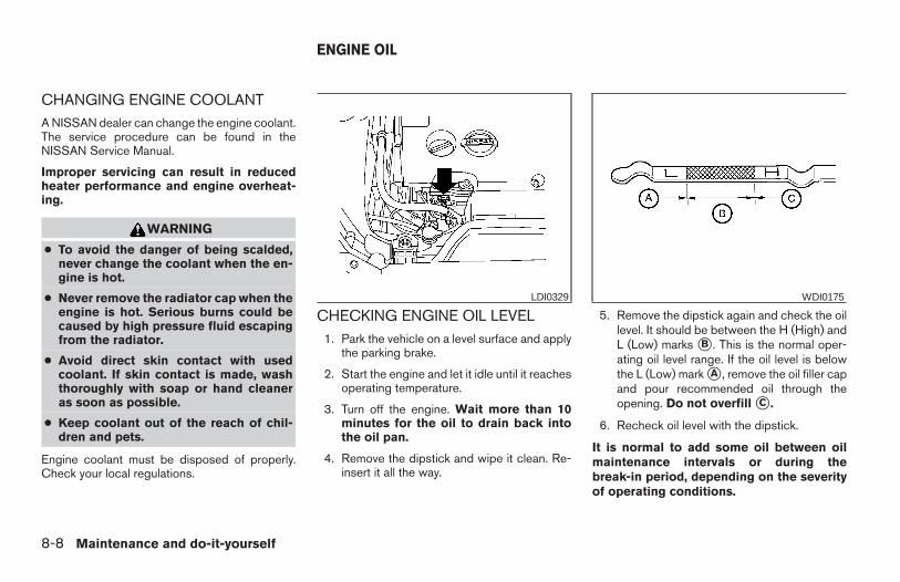
CHANGING ENGINE COOLANTA NISSAN dealer can change the engine coolant.The service procedure can be found in theNISSAN Service Manual.
Improper servicing can result in reducedheater performance and engine overheat-ing.
WARNING
● To avoid the danger of being scalded,never change the coolant when the en-gine is hot.
● Never remove the radiator cap when theengine is hot. Serious burns could becaused by high pressure fluid escapingfrom the radiator.
● Avoid direct skin contact with usedcoolant. If skin contact is made, washthoroughly with soap or hand cleaneras soon as possible.
● Keep coolant out of the reach of chil-dren and pets.
Engine coolant must be disposed of properly.Check your local regulations.
CHECKING ENGINE OIL LEVEL1. Park the vehicle on a level surface and apply
the parking brake.
2. Start the engine and let it idle until it reachesoperating temperature.
3. Turn off the engine. Wait more than 10minutes for the oil to drain back intothe oil pan.
4. Remove the dipstick and wipe it clean. Re-insert it all the way.
5. Remove the dipstick again and check the oillevel. It should be between the H (High) andL (Low) marks sB . This is the normal oper-ating oil level range. If the oil level is belowthe L (Low) mark sA , remove the oil filler capand pour recommended oil through theopening. Do not overfill sC .
6. Recheck oil level with the dipstick.
It is normal to add some oil between oilmaintenance intervals or during thebreak-in period, depending on the severityof operating conditions.
LDI0329 WDI0175
ENGINE OIL
8-8 Maintenance and do-it-yourself
Z REVIEW COPY:—2004 Maxima (max)Owners Manual (owners)—USA English (nna)10/20/03—arosenma X
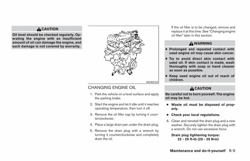
CAUTION
Oil level should be checked regularly. Op-erating the engine with an insufficientamount of oil can damage the engine, andsuch damage is not covered by warranty.
CHANGING ENGINE OIL
1. Park the vehicle on a level surface and applythe parking brake.
2. Start the engine and let it idle until it reachesoperating temperature, then turn it off.
3. Remove the oil filler cap by turning it coun-terclockwise.
4. Place a large drain pan under the drain plug.
5. Remove the drain plug with a wrench byturning it counterclockwise and completelydrain the oil.
If the oil filter is to be changed, remove andreplace it at this time. See “Changing engineoil filter” later in this section.
WARNING
● Prolonged and repeated contact withused engine oil may cause skin cancer.
● Try to avoid direct skin contact withused oil. If skin contact is made, washthoroughly with soap or hand cleaneras soon as possible.
● Keep used engine oil out of reach ofchildren.
CAUTION
Be careful not to burn yourself. The engineoil may be hot.
● Waste oil must be disposed of prop-erly.
● Check your local regulations.
6. Clean and reinstall the drain plug and a newwasher. Securely tighten the drain plug witha wrench. Do not use excessive force.
Drain plug tightening torque:22 - 29 ft-lb (29 - 39 N·m)
WDI0216
Maintenance and do-it-yourself 8-9
Z REVIEW COPY:—2004 Maxima (max)Owners Manual (owners)—USA English (nna)10/20/03—arosenma X
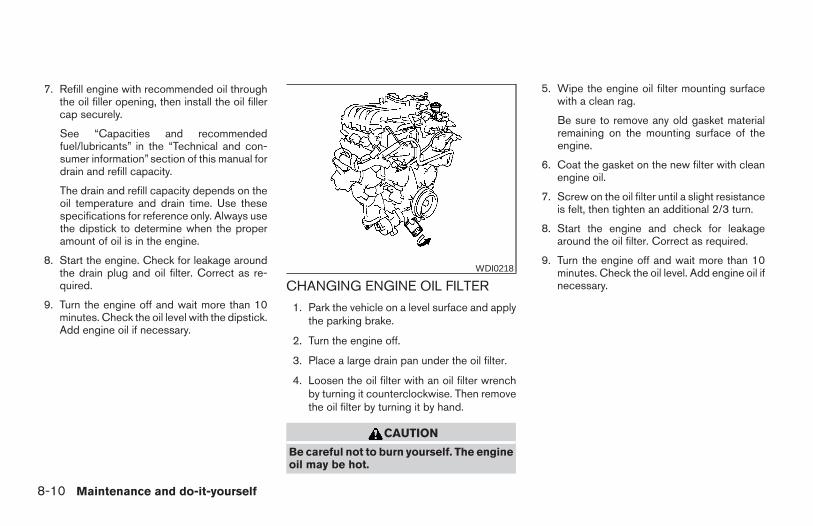
7. Refill engine with recommended oil throughthe oil filler opening, then install the oil fillercap securely.
See “Capacities and recommendedfuel/lubricants” in the “Technical and con-sumer information” section of this manual fordrain and refill capacity.
The drain and refill capacity depends on theoil temperature and drain time. Use thesespecifications for reference only. Always usethe dipstick to determine when the properamount of oil is in the engine.
8. Start the engine. Check for leakage aroundthe drain plug and oil filter. Correct as re-quired.
9. Turn the engine off and wait more than 10minutes. Check the oil level with the dipstick.Add engine oil if necessary.
CHANGING ENGINE OIL FILTER
1. Park the vehicle on a level surface and applythe parking brake.
2. Turn the engine off.
3. Place a large drain pan under the oil filter.
4. Loosen the oil filter with an oil filter wrenchby turning it counterclockwise. Then removethe oil filter by turning it by hand.
CAUTION
Be careful not to burn yourself. The engineoil may be hot.
5. Wipe the engine oil filter mounting surfacewith a clean rag.
Be sure to remove any old gasket materialremaining on the mounting surface of theengine.
6. Coat the gasket on the new filter with cleanengine oil.
7. Screw on the oil filter until a slight resistanceis felt, then tighten an additional 2/3 turn.
8. Start the engine and check for leakagearound the oil filter. Correct as required.
9. Turn the engine off and wait more than 10minutes. Check the oil level. Add engine oil ifnecessary.
WDI0218
8-10 Maintenance and do-it-yourself
Z REVIEW COPY:—2004 Maxima (max)Owners Manual (owners)—USA English (nna)10/20/03—arosenma X
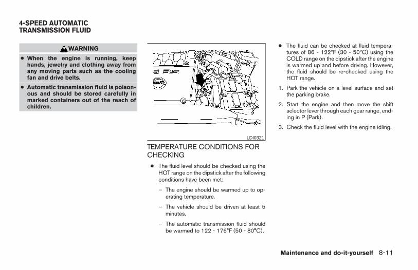
WARNING
● When the engine is running, keephands, jewelry and clothing away fromany moving parts such as the coolingfan and drive belts.
● Automatic transmission fluid is poison-ous and should be stored carefully inmarked containers out of the reach ofchildren.
TEMPERATURE CONDITIONS FORCHECKING
● The fluid level should be checked using theHOT range on the dipstick after the followingconditions have been met:
– The engine should be warmed up to op-erating temperature.
– The vehicle should be driven at least 5minutes.
– The automatic transmission fluid shouldbe warmed to 122 - 176°F (50 - 80°C).
● The fluid can be checked at fluid tempera-tures of 86 - 122°F (30 - 50°C) using theCOLD range on the dipstick after the engineis warmed up and before driving. However,the fluid should be re-checked using theHOT range.
1. Park the vehicle on a level surface and setthe parking brake.
2. Start the engine and then move the shiftselector lever through each gear range, end-ing in P (Park).
3. Check the fluid level with the engine idling.
LDI0321
4-SPEED AUTOMATICTRANSMISSION FLUID
Maintenance and do-it-yourself 8-11
Z REVIEW COPY:—2004 Maxima (max)Owners Manual (owners)—USA English (nna)10/20/03—arosenma X
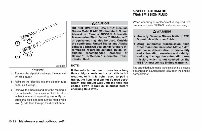
4. Remove the dipstick and wipe it clean withlint-free paper.
5. Reinsert the dipstick into the dipstick tubeas far as it will go.
6. Remove the dipstick and note the reading. Ifthe automatic transmission fluid level iswithin the normal operating range sB , noadditional fluid is required. If the fluid level islow sA add fluid through the dipstick tube.
CAUTION
DO NOT OVERFILL. Use ONLY GenuineNissan Matic D ATF (Continental U.S. andAlaska) or Canada NISSAN AutomaticTransmission Fluid. Dexron™ III/Mercon™or equivalent may also be used. Outsidethe continental United States and Alaskacontact a NISSAN dealership for more in-formation regarding suitable fluids, in-cluding recommended brand(s) ofDexron™ III/Mercon™ automatic trans-mission fluid.
NOTE:
If the vehicle has been driven for a longtime at high speeds, or in city traffic in hotweather, or if it is being used to pull atrailer, the fluid level cannot be read accu-rately. You should wait until the fluid hascooled down (about 30 minutes) beforechecking fluid level.
When checking or replacement is required, werecommend your NISSAN dealer for servicing.
WARNING
● Use only Genuine Nissan Matic K ATF.Do not mix with other fluids.
● Using automatic transmission fluidother than Genuine Nissan Matic K ATFwill cause deterioration in driveabilityand automatic transmission durability,and may damage the automatic trans-mission, which is not covered by theNISSAN new vehicle limited warranty.
The specified automatic transmission fluid is alsodescribed on caution labels located in the enginecompartment.
4–speedWDI0334
5-SPEED AUTOMATICTRANSMISSION FLUID
8-12 Maintenance and do-it-yourself
Z REVIEW COPY:—2004 Maxima (max)Owners Manual (owners)—USA English (nna)10/20/03—arosenma X
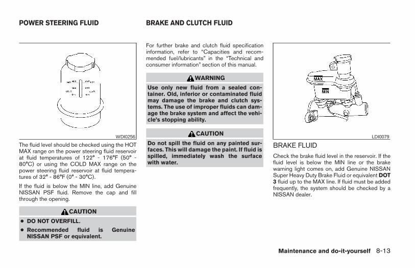
The fluid level should be checked using the HOTMAX range on the power steering fluid reservoirat fluid temperatures of 122° - 176°F (50° -80°C) or using the COLD MAX range on thepower steering fluid reservoir at fluid tempera-tures of 32° - 86°F (0° - 30°C).
If the fluid is below the MIN line, add GenuineNISSAN PSF fluid. Remove the cap and fillthrough the opening.
CAUTION
● DO NOT OVERFILL.
● Recommended fluid is GenuineNISSAN PSF or equivalent.
For further brake and clutch fluid specificationinformation, refer to “Capacities and recom-mended fuel/lubricants” in the “Technical andconsumer information” section of this manual.
WARNING
Use only new fluid from a sealed con-tainer. Old, inferior or contaminated fluidmay damage the brake and clutch sys-tems. The use of improper fluids can dam-age the brake system and affect the vehi-cle’s stopping ability.
CAUTION
Do not spill the fluid on any painted sur-faces. This will damage the paint. If fluid isspilled, immediately wash the surfacewith water.
BRAKE FLUIDCheck the brake fluid level in the reservoir. If thefluid level is below the MIN line or the brakewarning light comes on, add Genuine NISSANSuper Heavy Duty Brake Fluid or equivalent DOT3 fluid up to the MAX line. If fluid must be addedfrequently, the system should be checked by aNISSAN dealer.
WDI0256 LDI0079
POWER STEERING FLUID BRAKE AND CLUTCH FLUID
Maintenance and do-it-yourself 8-13
Z REVIEW COPY:—2004 Maxima (max)Owners Manual (owners)—USA English (nna)10/20/03—arosenma X
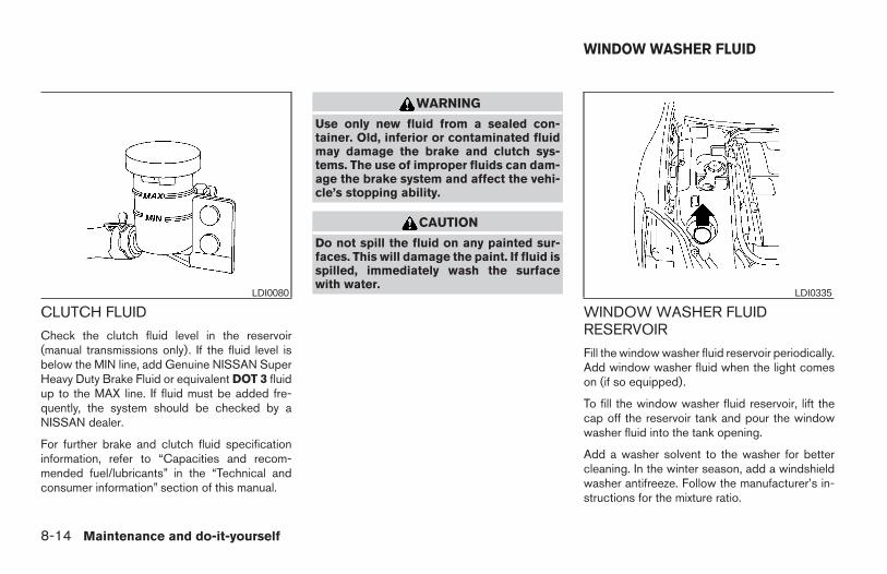
CLUTCH FLUID
Check the clutch fluid level in the reservoir(manual transmissions only). If the fluid level isbelow the MIN line, add Genuine NISSAN SuperHeavy Duty Brake Fluid or equivalent DOT 3 fluidup to the MAX line. If fluid must be added fre-quently, the system should be checked by aNISSAN dealer.
For further brake and clutch fluid specificationinformation, refer to “Capacities and recom-mended fuel/lubricants” in the “Technical andconsumer information” section of this manual.
WARNING
Use only new fluid from a sealed con-tainer. Old, inferior or contaminated fluidmay damage the brake and clutch sys-tems. The use of improper fluids can dam-age the brake system and affect the vehi-cle’s stopping ability.
CAUTION
Do not spill the fluid on any painted sur-faces. This will damage the paint. If fluid isspilled, immediately wash the surfacewith water.
WINDOW WASHER FLUIDRESERVOIR
Fill the window washer fluid reservoir periodically.Add window washer fluid when the light comeson (if so equipped).
To fill the window washer fluid reservoir, lift thecap off the reservoir tank and pour the windowwasher fluid into the tank opening.
Add a washer solvent to the washer for bettercleaning. In the winter season, add a windshieldwasher antifreeze. Follow the manufacturer’s in-structions for the mixture ratio.
LDI0080 LDI0335
WINDOW WASHER FLUID
8-14 Maintenance and do-it-yourself
Z REVIEW COPY:—2004 Maxima (max)Owners Manual (owners)—USA English (nna)10/20/03—arosenma X
Refill the reservoir more frequently when drivingconditions require an increased amount of win-dow washer fluid.
Recommended fluid is Genuine NISSAN Wind-shield Washer Concentrate Cleaner & Anti-freeze or equivalent.
CAUTION
● Do not substitute engine anti-freezecoolant for window washer solution.This may result in damage to the paint.
● Do not fill the window washer reservoirtank with washer fluid concentrates atfull strength. Some methyl alcoholbased washer fluid concentrates maypermanently stain the grille if spilledwhile filling the window washer reser-voir tank.
● Pre-mix washer fluid concentrates withwater to the manufacturer’s recom-mended levels before pouring the fluidinto the window washer reservoir tank.Do not use the window washer reservoirtank to mix the washer fluid concen-trate and water.
● Keep the battery surface clean and dry. Anycorrosion should be washed off with a solu-tion of baking soda and water.
● Make certain the terminal connections areclean and securely tightened.
● If the vehicle is not to be used for 30 days orlonger, disconnect the negative (-) batteryterminal cable to prevent discharge.
WARNING
● Do not expose the battery to flames orelectrical sparks. Hydrogen gas gener-ated by the battery is explosive. Do notallow battery fluid to contact your skin,eyes, fabrics or painted surfaces. Aftertouching a battery or battery cap, do nottouch or rub your eyes. Thoroughlywash your hands. If the acid contactsyour eyes, skin or clothing, immediatelyflush with water for at least 15 minutesand seek medical attention.
● Do not operate the vehicle if the fluid inthe battery is low. Low battery fluid cancause a higher load on the batterywhich can generate heat, reduce bat-tery life, and in some cases lead to anexplosion.
● When working on or near a battery, al-ways wear suitable eye protection andremove all jewelry.
● Battery posts, terminals and related ac-cessories contain lead and lead com-pounds. Wash hands after handling.
● Keep battery out of the reach ofchildren.
BATTERY
Maintenance and do-it-yourself 8-15
Z REVIEW COPY:—2004 Maxima (max)Owners Manual (owners)—USA English (nna)10/20/03—arosenma X
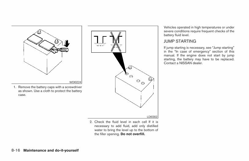
1. Remove the battery caps with a screwdriveras shown. Use a cloth to protect the batterycase.
2. Check the fluid level in each cell If it isnecessary to add fluid, add only distilledwater to bring the level up to the bottom ofthe filler opening. Do not overfill.
Vehicles operated in high temperatures or undersevere conditions require frequent checks of thebattery fluid level.
JUMP STARTINGIf jump starting is necessary, see “Jump starting”in the “In case of emergency” section of thismanual. If the engine does not start by jumpstarting, the battery may have to be replaced.Contact a NISSAN dealer.
WDI0224
LDI0302
8-16 Maintenance and do-it-yourself
Z REVIEW COPY:—2004 Maxima (max)Owners Manual (owners)—USA English (nna)10/20/03—arosenma X
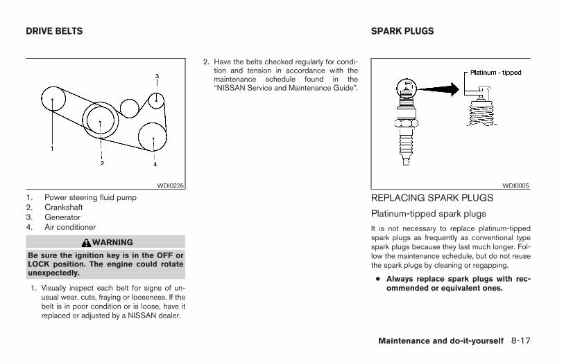
1. Power steering fluid pump2. Crankshaft3. Generator4. Air conditioner
WARNING
Be sure the ignition key is in the OFF orLOCK position. The engine could rotateunexpectedly.
1. Visually inspect each belt for signs of un-usual wear, cuts, fraying or looseness. If thebelt is in poor condition or is loose, have itreplaced or adjusted by a NISSAN dealer.
2. Have the belts checked regularly for condi-tion and tension in accordance with themaintenance schedule found in the“NISSAN Service and Maintenance Guide”.
REPLACING SPARK PLUGS
Platinum-tipped spark plugs
It is not necessary to replace platinum-tippedspark plugs as frequently as conventional typespark plugs because they last much longer. Fol-low the maintenance schedule, but do not reusethe spark plugs by cleaning or regapping.
● Always replace spark plugs with rec-ommended or equivalent ones.
WDI0226 WDI0005
DRIVE BELTS SPARK PLUGS
Maintenance and do-it-yourself 8-17
Z REVIEW COPY:—2004 Maxima (max)Owners Manual (owners)—USA English (nna)10/22/03—betty X
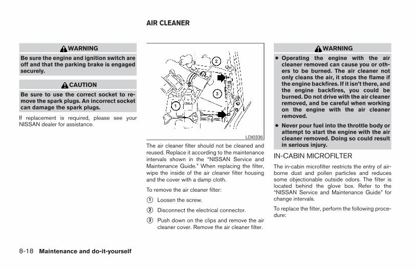
WARNING
Be sure the engine and ignition switch areoff and that the parking brake is engagedsecurely.
CAUTION
Be sure to use the correct socket to re-move the spark plugs. An incorrect socketcan damage the spark plugs.
If replacement is required, please see yourNISSAN dealer for assistance.
The air cleaner filter should not be cleaned andreused. Replace it according to the maintenanceintervals shown in the “NISSAN Service andMaintenance Guide.” When replacing the filter,wipe the inside of the air cleaner filter housingand the cover with a damp cloth.
To remove the air cleaner filter:
s1 Loosen the screw.
s2 Disconnect the electrical connector.
s3 Push down on the clips and remove the aircleaner cover. Remove the air cleaner filter.
WARNING
● Operating the engine with the aircleaner removed can cause you or oth-ers to be burned. The air cleaner notonly cleans the air, it stops the flame ifthe engine backfires. If it isn’t there, andthe engine backfires, you could beburned. Do not drive with the air cleanerremoved, and be careful when workingon the engine with the air cleanerremoved.
● Never pour fuel into the throttle body orattempt to start the engine with the aircleaner removed. Doing so could resultin serious injury.
IN-CABIN MICROFILTERThe in-cabin microfilter restricts the entry of air-borne dust and pollen particles and reducessome objectionable outside odors. The filter islocated behind the glove box. Refer to the“NISSAN Service and Maintenance Guide” forchange intervals.
To replace the filter, perform the following proce-dure:
LDI0336
AIR CLEANER
8-18 Maintenance and do-it-yourself
Z REVIEW COPY:—2004 Maxima (max)Owners Manual (owners)—USA English (nna)10/20/03—arosenma X
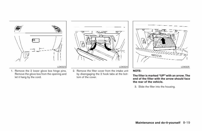
1. Remove the 2 lower glove box hinge pins.Remove the glove box from the opening andlet it hang by the cord.
2. Remove the filter cover from the intake unitby disengaging the 2 hook tabs at the bot-tom of the cover.
NOTE:
The filter is marked “UP”with an arrow. Theend of the filter with the arrow should facethe rear of the vehicle.
3. Slide the filter into the housing.
LDI0323 LDI0324 LDI0325
Maintenance and do-it-yourself 8-19
Z REVIEW COPY:—2004 Maxima (max)Owners Manual (owners)—USA English (nna)10/20/03—arosenma X
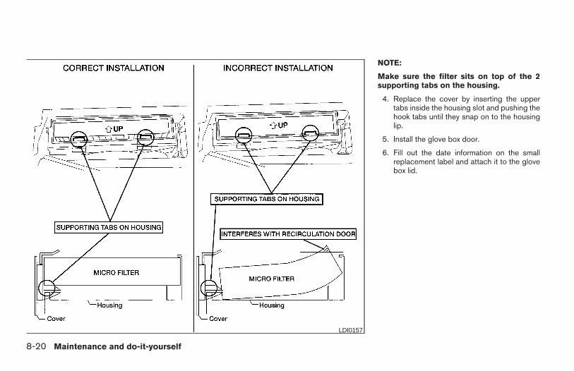
NOTE:
Make sure the filter sits on top of the 2supporting tabs on the housing.
4. Replace the cover by inserting the uppertabs inside the housing slot and pushing thehook tabs until they snap on to the housinglip.
5. Install the glove box door.
6. Fill out the date information on the smallreplacement label and attach it to the glovebox lid.
LDI0157
8-20 Maintenance and do-it-yourself
Z REVIEW COPY:—2004 Maxima (max)Owners Manual (owners)—USA English (nna)10/20/03—arosenma X
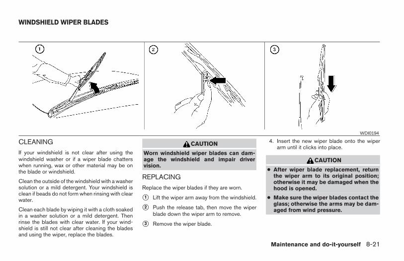
CLEANING
If your windshield is not clear after using thewindshield washer or if a wiper blade chatterswhen running, wax or other material may be onthe blade or windshield.
Clean the outside of the windshield with a washersolution or a mild detergent. Your windshield isclean if beads do not form when rinsing with clearwater.
Clean each blade by wiping it with a cloth soakedin a washer solution or a mild detergent. Thenrinse the blades with clear water. If your wind-shield is still not clear after cleaning the bladesand using the wiper, replace the blades.
CAUTION
Worn windshield wiper blades can dam-age the windshield and impair drivervision.
REPLACING
Replace the wiper blades if they are worn.
s1 Lift the wiper arm away from the windshield.
s2 Push the release tab, then move the wiperblade down the wiper arm to remove.
s3 Remove the wiper blade.
4. Insert the new wiper blade onto the wiperarm until it clicks into place.
CAUTION
● After wiper blade replacement, returnthe wiper arm to its original position;otherwise it may be damaged when thehood is opened.
● Make sure the wiper blades contact theglass; otherwise the arms may be dam-aged from wind pressure.
WDI0194
WINDSHIELD WIPER BLADES
Maintenance and do-it-yourself 8-21
Z REVIEW COPY:—2004 Maxima (max)Owners Manual (owners)—USA English (nna)10/20/03—arosenma X
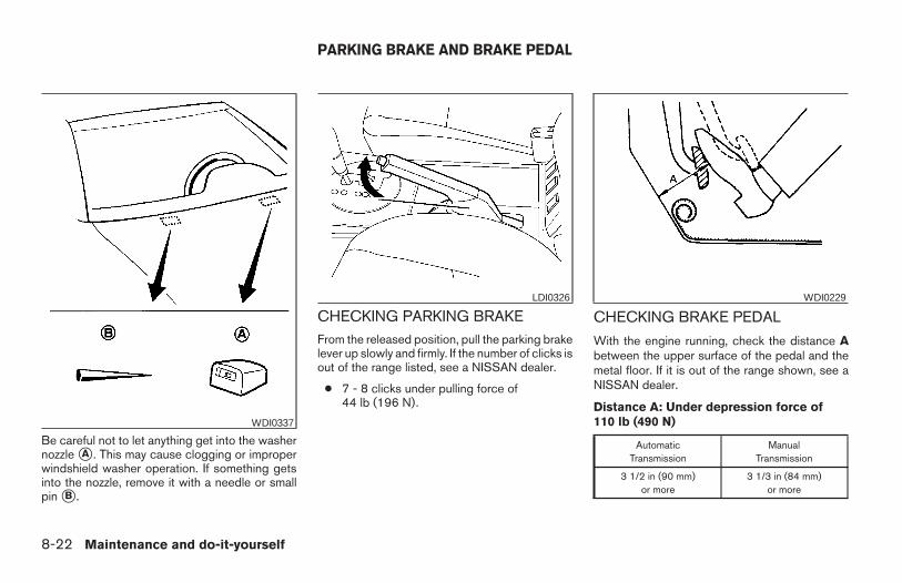
Be careful not to let anything get into the washernozzle sA . This may cause clogging or improperwindshield washer operation. If something getsinto the nozzle, remove it with a needle or smallpin sB .
CHECKING PARKING BRAKEFrom the released position, pull the parking brakelever up slowly and firmly. If the number of clicks isout of the range listed, see a NISSAN dealer.
● 7 - 8 clicks under pulling force of44 lb (196 N).
CHECKING BRAKE PEDAL
With the engine running, check the distance Abetween the upper surface of the pedal and themetal floor. If it is out of the range shown, see aNISSAN dealer.
Distance A: Under depression force of110 lb (490 N)
AutomaticTransmission
ManualTransmission
3 1/2 in (90 mm)or more
3 1/3 in (84 mm)or more
WDI0337
LDI0326 WDI0229
PARKING BRAKE AND BRAKE PEDAL
8-22 Maintenance and do-it-yourself
Z REVIEW COPY:—2004 Maxima (max)Owners Manual (owners)—USA English (nna)10/20/03—arosenma X
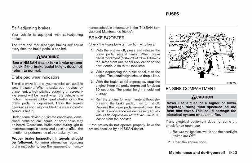
Self-adjusting brakes
Your vehicle is equipped with self-adjustingbrakes.
The front and rear disc-type brakes self-adjustevery time the brake pedal is applied.
WARNING
See a NISSAN dealer for a brake systemcheck if the brake pedal height does notreturn to normal.
Brake pad wear indicatorsThe disc brake pads on your vehicle have audiblewear indicators. When a brake pad requires re-placement, a high pitched scraping or screech-ing sound will be heard when the vehicle is inmotion. The noise will be heard whether or not thebrake pedal is depressed. Have the brakeschecked as soon as possible if the wear indicatorsound is heard.
Under some driving or climate conditions, occa-sional brake squeak, squeal or other noise maybe heard. Occasional brake noise during light tomoderate stops is normal and does not affect thefunction or performance of the brake system.
Proper brake inspection intervals shouldbe followed. For more information regardingbrake inspections, see the appropriate mainte-
nance schedule information in the “NISSAN Ser-vice and Maintenance Guide”.
BRAKE BOOSTERCheck the brake booster function as follows:
1. With the engine off, press and release thebrake pedal several times. When brakepedal movement (distance of travel) remainsthe same from one pedal application to thenext, continue on to the next step.
2. While depressing the brake pedal, start theengine. The pedal height should drop a little.
3. With the brake pedal depressed, stop theengine. Keep the pedal depressed for about30 seconds. The pedal height should notchange.
4. Run the engine for one minute without de-pressing the brake pedal, then turn it off.Depress the brake pedal several times. Thepedal travel distance will decrease graduallywith each depression as the vacuum is re-leased from the booster.
If the brakes do not operate properly, have thebrakes checked by a NISSAN dealer.
ENGINE COMPARTMENT
CAUTION
Never use a fuse of a higher or loweramperage rating than specified on thefuse box cover. This could damage theelectrical system or cause a fire.
If any electrical equipment does not come on,check for an open fuse.
1. Be sure the ignition switch and the headlightswitch are OFF.
2. Open the engine hood.
LDI0327
FUSES
Maintenance and do-it-yourself 8-23
Z REVIEW COPY:—2004 Maxima (max)Owners Manual (owners)—USA English (nna)10/20/03—arosenma X
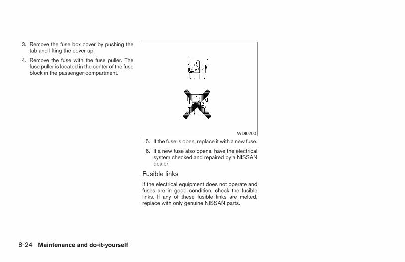
3. Remove the fuse box cover by pushing thetab and lifting the cover up.
4. Remove the fuse with the fuse puller. Thefuse puller is located in the center of the fuseblock in the passenger compartment.
5. If the fuse is open, replace it with a new fuse.
6. If a new fuse also opens, have the electricalsystem checked and repaired by a NISSANdealer.
Fusible linksIf the electrical equipment does not operate andfuses are in good condition, check the fusiblelinks. If any of these fusible links are melted,replace with only genuine NISSAN parts.
WDI0200
8-24 Maintenance and do-it-yourself
Z REVIEW COPY:—2004 Maxima (max)Owners Manual (owners)—USA English (nna)10/20/03—arosenma X
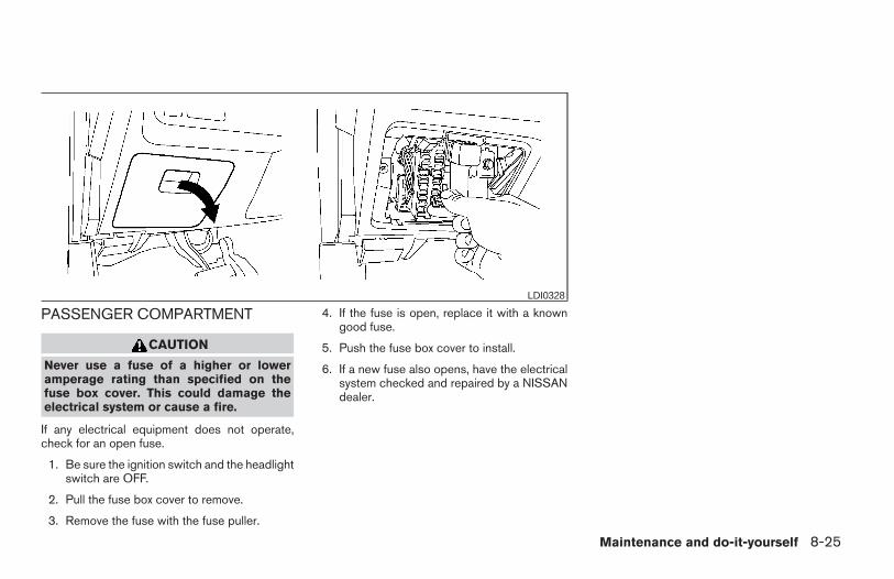
PASSENGER COMPARTMENT
CAUTION
Never use a fuse of a higher or loweramperage rating than specified on thefuse box cover. This could damage theelectrical system or cause a fire.
If any electrical equipment does not operate,check for an open fuse.
1. Be sure the ignition switch and the headlightswitch are OFF.
2. Pull the fuse box cover to remove.
3. Remove the fuse with the fuse puller.
4. If the fuse is open, replace it with a knowngood fuse.
5. Push the fuse box cover to install.
6. If a new fuse also opens, have the electricalsystem checked and repaired by a NISSANdealer.
LDI0328
Maintenance and do-it-yourself 8-25
Z REVIEW COPY:—2004 Maxima (max)Owners Manual (owners)—USA English (nna)10/20/03—arosenma X
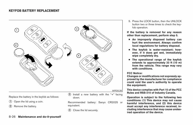
Replace the battery in the keyfob as follows:
s1 Open the lid using a coin.
s2 Remove the battery.
s3 Install a new battery with the “+” facingdown.
Recommended battery: Sanyo CR2025 orequivalent.
s4 Close the lid securely.
5. Press the LOCK button, then the UNLOCKbutton two or three times to check the key-fob operation.
If the battery is removed for any reasonother than replacement, perform step 5.
● An improperly disposed battery canhurt the environment. Always confirmlocal regulations for battery disposal.
● The keyfob is water-resistant; how-ever, if it does get wet, immediatelywipe completely dry.
● The operational range of the keyfobextends to approximately 33 ft (10 m)from the vehicle. This range may varywith conditions.
FCC Notice:Changes or modifications not expressly ap-proved by the manufacturer for compliancecould void the user’s authority to operatethe equipment.
This device complies with Part 15 of the FCCRules and RSS-210 of Industry Canada.
Operation is subject to the following twoconditions: (1) This device may not causeharmful interference, and (2) this devicemust accept any interference received, in-cluding interference that may cause undes-ired operation of the device.
WPD0136
KEYFOB BATTERY REPLACEMENT
8-26 Maintenance and do-it-yourself
Z REVIEW COPY:—2004 Maxima (max)Owners Manual (owners)—USA English (nna)10/20/03—arosenma X
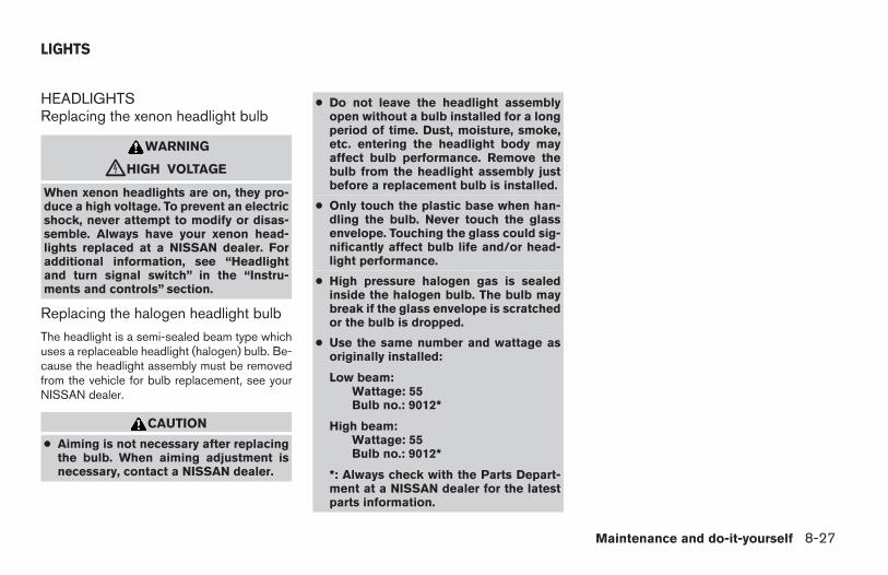
HEADLIGHTSReplacing the xenon headlight bulb
WARNING
cHIGH VOLTAGE
When xenon headlights are on, they pro-duce a high voltage. To prevent an electricshock, never attempt to modify or disas-semble. Always have your xenon head-lights replaced at a NISSAN dealer. Foradditional information, see “Headlightand turn signal switch” in the “Instru-ments and controls” section.
Replacing the halogen headlight bulb
The headlight is a semi-sealed beam type whichuses a replaceable headlight (halogen) bulb. Be-cause the headlight assembly must be removedfrom the vehicle for bulb replacement, see yourNISSAN dealer.
CAUTION
● Aiming is not necessary after replacingthe bulb. When aiming adjustment isnecessary, contact a NISSAN dealer.
● Do not leave the headlight assemblyopen without a bulb installed for a longperiod of time. Dust, moisture, smoke,etc. entering the headlight body mayaffect bulb performance. Remove thebulb from the headlight assembly justbefore a replacement bulb is installed.
● Only touch the plastic base when han-dling the bulb. Never touch the glassenvelope. Touching the glass could sig-nificantly affect bulb life and/or head-light performance.
● High pressure halogen gas is sealedinside the halogen bulb. The bulb maybreak if the glass envelope is scratchedor the bulb is dropped.
● Use the same number and wattage asoriginally installed:
Low beam:Wattage: 55Bulb no.: 9012*
High beam:Wattage: 55Bulb no.: 9012*
*: Always check with the Parts Depart-ment at a NISSAN dealer for the latestparts information.
LIGHTS
Maintenance and do-it-yourself 8-27
Z REVIEW COPY:—2004 Maxima (max)Owners Manual (owners)—USA English (nna)10/20/03—arosenma X
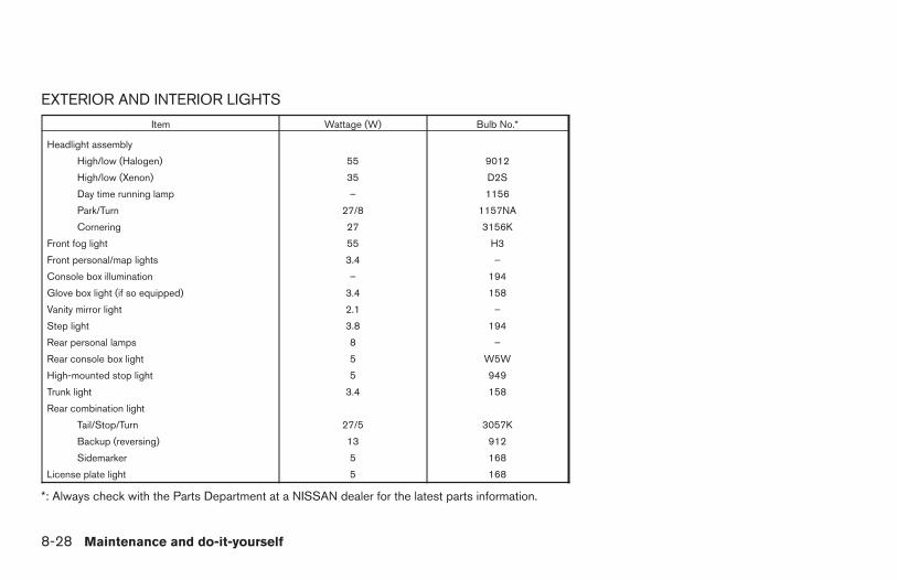
EXTERIOR AND INTERIOR LIGHTS
Item Wattage (W) Bulb No.*
Headlight assembly
High/low (Halogen) 55 9012
High/low (Xenon) 35 D2S
Day time running lamp – 1156
Park/Turn 27/8 1157NA
Cornering 27 3156K
Front fog light 55 H3
Front personal/map lights 3.4 –
Console box illumination – 194
Glove box light (if so equipped) 3.4 158
Vanity mirror light 2.1 –
Step light 3.8 194
Rear personal lamps 8 –
Rear console box light 5 W5W
High-mounted stop light 5 949
Trunk light 3.4 158
Rear combination light
Tail/Stop/Turn 27/5 3057K
Backup (reversing) 13 912
Sidemarker 5 168
License plate light 5 168
*: Always check with the Parts Department at a NISSAN dealer for the latest parts information.
8-28 Maintenance and do-it-yourself
Z REVIEW COPY:—2004 Maxima (max)Owners Manual (owners)—USA English (nna)10/20/03—arosenma X
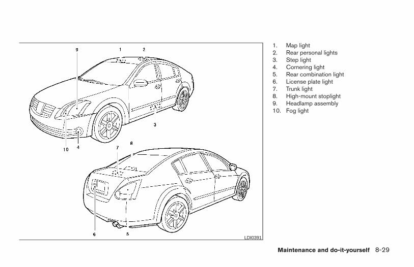
1. Map light2. Rear personal lights3. Step light4. Cornering light5. Rear combination light6. License plate light7. Trunk light8. High-mount stoplight9. Headlamp assembly10. Fog light
LDI0391
Maintenance and do-it-yourself 8-29
Z REVIEW COPY:—2004 Maxima (max)Owners Manual (owners)—USA English (nna)10/20/03—arosenma X
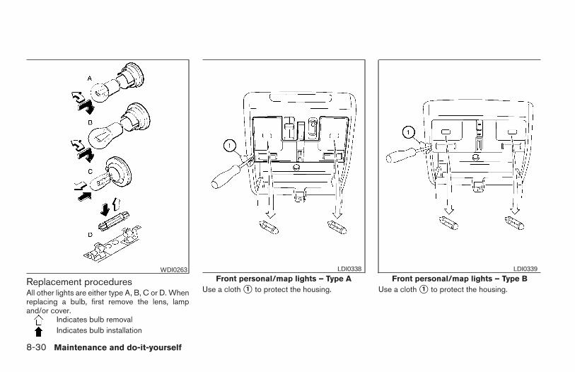
Replacement proceduresAll other lights are either type A, B, C or D. Whenreplacing a bulb, first remove the lens, lampand/or cover.
Indicates bulb removalIndicates bulb installation
Use a cloth s1 to protect the housing. Use a cloth s1 to protect the housing.
WDI0263Front personal/map lights – Type A
LDI0338
Front personal/map lights – Type BLDI0339
8-30 Maintenance and do-it-yourself
Z REVIEW COPY:—2004 Maxima (max)Owners Manual (owners)—USA English (nna)10/20/03—arosenma X
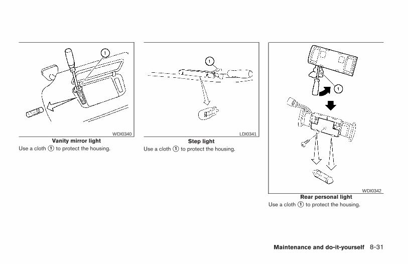
Use a cloth s1 to protect the housing. Use a cloth s1 to protect the housing.
Use a cloth s1 to protect the housing.
Vanity mirror lightWDI0340
Step lightLDI0341
Rear personal lightWDI0342
Maintenance and do-it-yourself 8-31
Z REVIEW COPY:—2004 Maxima (max)Owners Manual (owners)—USA English (nna)10/20/03—arosenma X
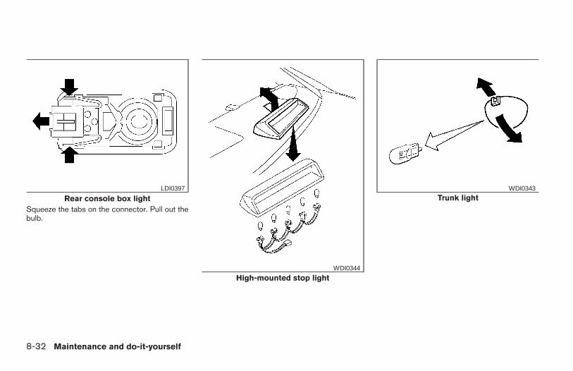
Squeeze the tabs on the connector. Pull out thebulb.
Rear console box lightLDI0397
High-mounted stop lightWDI0344
Trunk lightWDI0343
8-32 Maintenance and do-it-yourself
Z REVIEW COPY:—2004 Maxima (max)Owners Manual (owners)—USA English (nna)10/20/03—arosenma X
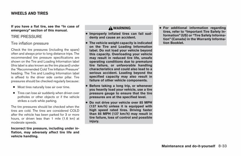
If you have a flat tire, see the “In case ofemergency” section of this manual.
TIRE PRESSURE
Tire inflation pressure
Check the tire pressures (including the spare)often and always prior to long distance trips. Therecommended tire pressure specifications areshown on the Tire and Loading Information label(this label is also known as the tire placard) underthe 9Recommended Cold Tire Inflation Pressure9heading. The Tire and Loading Information labelis affixed to the driver side center pillar. Tirepressures should be checked regularly because:
● Most tires naturally lose air over time.
● Tires can lose air suddenly when driven overpotholes or other objects or if the vehiclestrikes a curb while parking.
The tire pressures should be checked when thetires are cold. The tires are considered COLDafter the vehicle has been parked for 3 or morehours, or driven less than 1 mile (1.6 km) atmoderate speeds.
Incorrect tire pressure, including under in-flation, may adversely affect tire life andvehicle handling.
WARNING
● Improperly inflated tires can fail sud-denly and cause an accident.
● The vehicle weight capacity is indicatedon the Tire and Loading Informationlabel. Do not load your vehicle beyondthis capacity. Overloading your vehiclemay result in reduced tire life, unsafeoperating conditions due to prematuretire failure, or unfavorable handlingcharacteristics and could also lead to aserious accident. Loading beyond thespecified capacity may also result infailure of other vehicle components.
● Before taking a long trip, or wheneveryou heavily load your vehicle, use a tirepressure gauge to ensure that the tirepressures are at the specified level.
● Do not drive your vehicle over 85 MPH(137 km/h) unless it is equipped withhigh speed rated tires. Driving fasterthan 85 MPH (137 km/h) may result intire failure, loss of control and possibleinjury.
● For additional information regardingtires, refer to “Important Tire Safety In-formation” (US) or “Tire Safety Informa-tion” (Canada) in the Warranty Informa-tion Booklet.
WHEELS AND TIRES
Maintenance and do-it-yourself 8-33
Z REVIEW COPY:—2004 Maxima (max)Owners Manual (owners)—USA English (nna)10/20/03—arosenma X
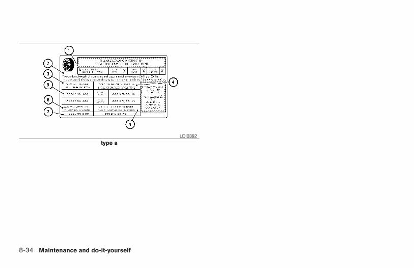
type aLDI0392
8-34 Maintenance and do-it-yourself
Z REVIEW COPY:—2004 Maxima (max)Owners Manual (owners)—USA English (nna)10/20/03—arosenma X
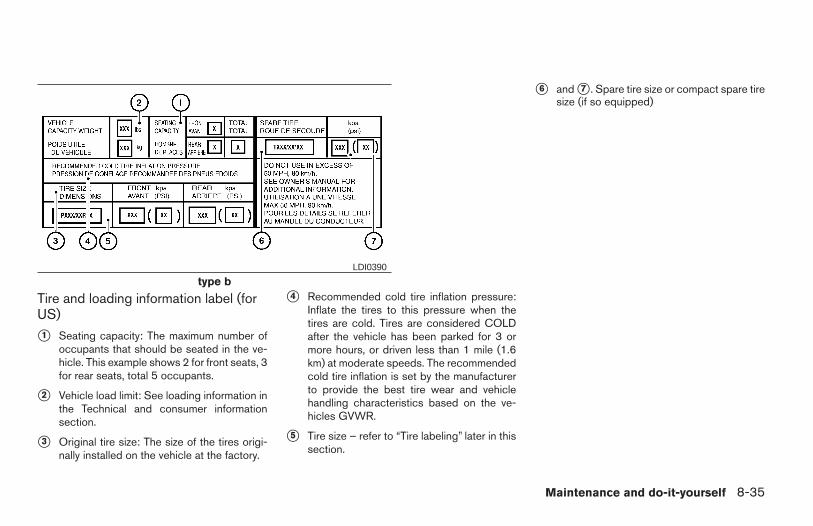
Tire and loading information label (forUS)
s1 Seating capacity: The maximum number ofoccupants that should be seated in the ve-hicle. This example shows 2 for front seats, 3for rear seats, total 5 occupants.
s2 Vehicle load limit: See loading information inthe Technical and consumer informationsection.
s3 Original tire size: The size of the tires origi-nally installed on the vehicle at the factory.
s4 Recommended cold tire inflation pressure:Inflate the tires to this pressure when thetires are cold. Tires are considered COLDafter the vehicle has been parked for 3 ormore hours, or driven less than 1 mile (1.6km) at moderate speeds. The recommendedcold tire inflation is set by the manufacturerto provide the best tire wear and vehiclehandling characteristics based on the ve-hicles GVWR.
s5 Tire size – refer to “Tire labeling” later in thissection.
s6 and s7 . Spare tire size or compact spare tiresize (if so equipped)
type bLDI0390
Maintenance and do-it-yourself 8-35
Z REVIEW COPY:—2004 Maxima (max)Owners Manual (owners)—USA English (nna)10/20/03—arosenma X
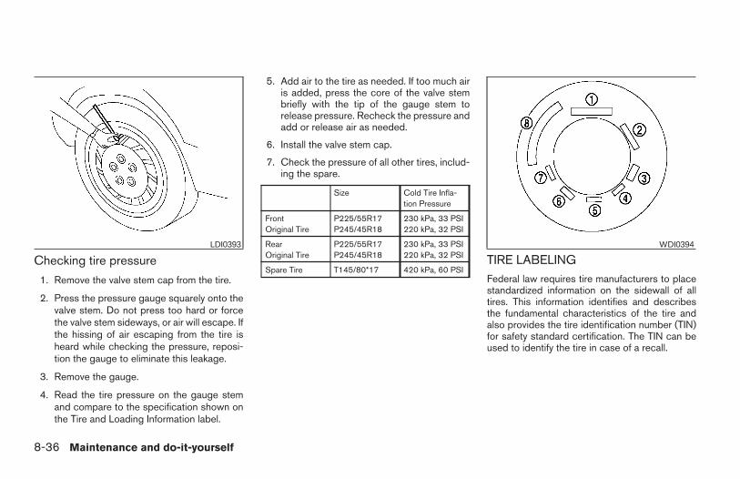
Checking tire pressure
1. Remove the valve stem cap from the tire.
2. Press the pressure gauge squarely onto thevalve stem. Do not press too hard or forcethe valve stem sideways, or air will escape. Ifthe hissing of air escaping from the tire isheard while checking the pressure, reposi-tion the gauge to eliminate this leakage.
3. Remove the gauge.
4. Read the tire pressure on the gauge stemand compare to the specification shown onthe Tire and Loading Information label.
5. Add air to the tire as needed. If too much airis added, press the core of the valve stembriefly with the tip of the gauge stem torelease pressure. Recheck the pressure andadd or release air as needed.
6. Install the valve stem cap.
7. Check the pressure of all other tires, includ-ing the spare.
Size Cold Tire Infla-tion Pressure
FrontOriginal Tire
P225/55R17P245/45R18
230 kPa, 33 PSI220 kPa, 32 PSI
RearOriginal Tire
P225/55R17P245/45R18
230 kPa, 33 PSI220 kPa, 32 PSI
Spare Tire T145/80*17 420 kPa, 60 PSITIRE LABELINGFederal law requires tire manufacturers to placestandardized information on the sidewall of alltires. This information identifies and describesthe fundamental characteristics of the tire andalso provides the tire identification number (TIN)for safety standard certification. The TIN can beused to identify the tire in case of a recall.
LDI0393 WDI0394
8-36 Maintenance and do-it-yourself
Z REVIEW COPY:—2004 Maxima (max)Owners Manual (owners)—USA English (nna)10/20/03—arosenma X
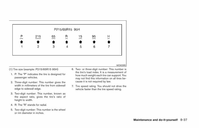
(1) Tire size (example: P215/65R15 95H)
1. P: The 9P9 indicates the tire is designed forpassenger vehicles.
2. Three-digit number: This number gives thewidth in millimeters of the tire from sidewalledge to sidewall edge.
3. Two-digit number: This number, known asthe aspect ratio, gives the tire’s ratio ofheight to width.
4. R: The 9R9 stands for radial.
5. Two-digit number: This number is the wheelor rim diameter in inches.
6. Two- or three-digit number: This number isthe tire’s load index. It is a measurement ofhow much weight each tire can support. Youmay not find this information on all tires be-cause it is not required by law.
7. Tire speed rating. You should not drive thevehicle faster than the tire speed rating.
WDI0395
Maintenance and do-it-yourself 8-37
Z REVIEW COPY:—2004 Maxima (max)Owners Manual (owners)—USA English (nna)10/20/03—arosenma X
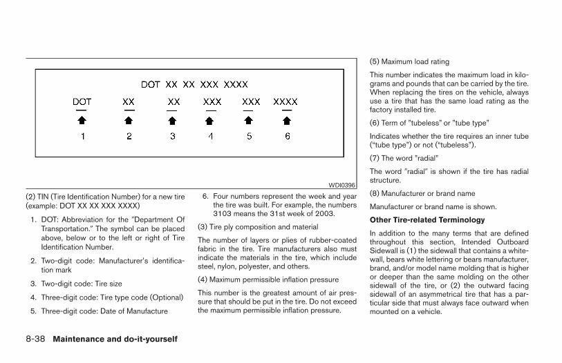
(2) TIN (Tire Identification Number) for a new tire(example: DOT XX XX XXX XXXX)
1. DOT: Abbreviation for the 9Department OfTransportation.9 The symbol can be placedabove, below or to the left or right of TireIdentification Number.
2. Two-digit code: Manufacturer’s identifica-tion mark
3. Two-digit code: Tire size
4. Three-digit code: Tire type code (Optional)
5. Three-digit code: Date of Manufacture
6. Four numbers represent the week and yearthe tire was built. For example, the numbers3103 means the 31st week of 2003.
(3) Tire ply composition and material
The number of layers or plies of rubber-coatedfabric in the tire. Tire manufacturers also mustindicate the materials in the tire, which includesteel, nylon, polyester, and others.
(4) Maximum permissible inflation pressure
This number is the greatest amount of air pres-sure that should be put in the tire. Do not exceedthe maximum permissible inflation pressure.
(5) Maximum load rating
This number indicates the maximum load in kilo-grams and pounds that can be carried by the tire.When replacing the tires on the vehicle, alwaysuse a tire that has the same load rating as thefactory installed tire.
(6) Term of ”tubeless” or ”tube type”
Indicates whether the tire requires an inner tube(“tube type”) or not (“tubeless”).
(7) The word ”radial”
The word 9radial9 is shown if the tire has radialstructure.
(8) Manufacturer or brand name
Manufacturer or brand name is shown.
Other Tire-related Terminology
In addition to the many terms that are definedthroughout this section, Intended OutboardSidewall is (1) the sidewall that contains a white-wall, bears white lettering or bears manufacturer,brand, and/or model name molding that is higheror deeper than the same molding on the othersidewall of the tire, or (2) the outward facingsidewall of an asymmetrical tire that has a par-ticular side that must always face outward whenmounted on a vehicle.
WDI0396
8-38 Maintenance and do-it-yourself
Z REVIEW COPY:—2004 Maxima (max)Owners Manual (owners)—USA English (nna)10/20/03—arosenma X
TYPES OF TIRES
WARNING
● When changing or replacing tires, besure all four tires are of the same type(i.e., Summer, All Season or Snow) andconstruction. A NISSAN dealer may beable to help you with information abouttire type, size, speed rating and avail-ability. Replacement tires may have alower speed rating than the factoryequipped tires, and may not match thepotential maximum vehicle speed.Never exceed the maximum speed rat-ing of the tire.
● For additional information regardingtires, refer to “Important Tire Safety In-formation” (US) or “Tire Safety Informa-tion” (Canada) in the Warranty Informa-tion Booklet.
All season tires
NISSAN specifies All Season tires on some mod-els to provide good performance all year, includ-ing snowy and icy road conditions. All Seasontires are identified by ALL SEASON and/or M&Son the tire sidewall. Snow tires have better snowtraction than All Season tires and may be moreappropriate in some areas.
Summer tires
NISSAN specifies summer tires on some modelsto provide superior performance on dry roads.Summer tire performance is substantially re-duced in snow and ice. Summer tires do not havethe tire traction rating “M&S” on the tire sidewall.
If you plan to operate your vehicle in snowy or icyconditions, NISSAN recommends the use ofSNOW tires or ALL SEASON tires on all fourwheels.
Snow tiresIf snow tires are needed, it is necessary to selecttires equivalent in size and load rating to theoriginal equipment tires. If you do not, it canadversely affect the safety and handling of yourvehicle.
Generally, snow tires have lower speed ratingsthan factory equipped tires and may not matchthe potential maximum vehicle speed. Never ex-ceed the maximum speed rating of the tire.
If you install snow tires, they must be the samesize, brand, construction and tread pattern on allfour wheels.
For additional traction on icy roads, studded tiresmay be used. However, some U.S. states andCanadian provinces prohibit their use. Checklocal, state and provincial laws before installing
studded tires. Skid and traction capabilities ofstudded snow tires on wet or dry surfaces may bepoorer than that of non-studded snow tires.
TIRE CHAINS
Use of tire chains may be prohibited according tolocation. Check the local laws before installingtire chains. When installing tire chains, make surethey are the proper size for the tires on yourvehicle and are installed according to the chainmanufacturer’s suggestions. Use only SAEclass “S” chains. Class “S” chains are used onvehicles with restricted tire to vehicle clearance.Vehicles that can use Class “S” chains are de-signed to meet the minimum clearances betweenthe tire and the closest vehicle suspension orbody component required to accommodate theuse of a winter traction device (tire chains orcables). The minimum clearances are determinedusing the factory equipped tires. Other types maydamage your vehicle. Use chain tensioners whenrecommended by the tire chain manufacturer toensure a tight fit. Loose end links of the tire chainmust be secured or removed to prevent the pos-sibility of whipping action damage to the fendersor underbody. If possible, avoid fully loading yourvehicle when using tire chains. In addition, driveat a reduced speed. Otherwise, your vehicle maybe damaged and/or vehicle handling and perfor-mance may be adversely affected.
Maintenance and do-it-yourself 8-39
Z REVIEW COPY:—2004 Maxima (max)Owners Manual (owners)—USA English (nna)10/20/03—arosenma X
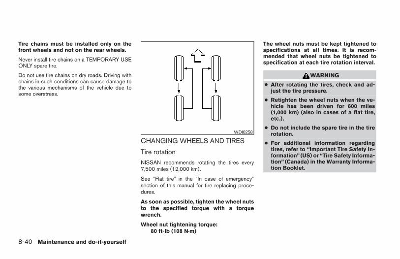
Tire chains must be installed only on thefront wheels and not on the rear wheels.
Never install tire chains on a TEMPORARY USEONLY spare tire.
Do not use tire chains on dry roads. Driving withchains in such conditions can cause damage tothe various mechanisms of the vehicle due tosome overstress.
CHANGING WHEELS AND TIRES
Tire rotation
NISSAN recommends rotating the tires every7,500 miles (12,000 km).
See “Flat tire” in the “In case of emergency”section of this manual for tire replacing proce-dures.
As soon as possible, tighten the wheel nutsto the specified torque with a torquewrench.
Wheel nut tightening torque:80 ft-lb (108 N·m)
The wheel nuts must be kept tightened tospecifications at all times. It is recom-mended that wheel nuts be tightened tospecification at each tire rotation interval.
WARNING
● After rotating the tires, check and ad-just the tire pressure.
● Retighten the wheel nuts when the ve-hicle has been driven for 600 miles(1,000 km) (also in cases of a flat tire,etc.).
● Do not include the spare tire in the tirerotation.
● For additional information regardingtires, refer to “Important Tire Safety In-formation” (US) or “Tire Safety Informa-tion” (Canada) in the Warranty Informa-tion Booklet.
WDI0258
8-40 Maintenance and do-it-yourself
Z REVIEW COPY:—2004 Maxima (max)Owners Manual (owners)—USA English (nna)10/20/03—arosenma X
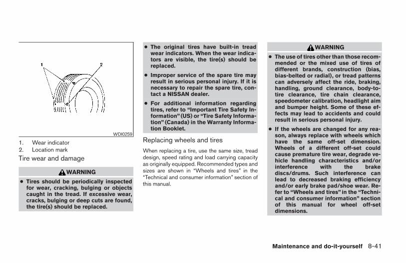
1. Wear indicator2. Location mark
Tire wear and damage
WARNING
● Tires should be periodically inspectedfor wear, cracking, bulging or objectscaught in the tread. If excessive wear,cracks, bulging or deep cuts are found,the tire(s) should be replaced.
● The original tires have built-in treadwear indicators. When the wear indica-tors are visible, the tire(s) should bereplaced.
● Improper service of the spare tire mayresult in serious personal injury. If it isnecessary to repair the spare tire, con-tact a NISSAN dealer.
● For additional information regardingtires, refer to “Important Tire Safety In-formation” (US) or “Tire Safety Informa-tion” (Canada) in the Warranty Informa-tion Booklet.
Replacing wheels and tires
When replacing a tire, use the same size, treaddesign, speed rating and load carrying capacityas originally equipped. Recommended types andsizes are shown in “Wheels and tires” in the“Technical and consumer information” section ofthis manual.
WARNING
● The use of tires other than those recom-mended or the mixed use of tires ofdifferent brands, construction (bias,bias-belted or radial), or tread patternscan adversely affect the ride, braking,handling, ground clearance, body-to-tire clearance, tire chain clearance,speedometer calibration, headlight aimand bumper height. Some of these ef-fects may lead to accidents and couldresult in serious personal injury.
● If the wheels are changed for any rea-son, always replace with wheels whichhave the same off-set dimension.Wheels of a different off-set couldcause premature tire wear, degrade ve-hicle handling characteristics and/orinterference with the brakediscs/drums. Such interference canlead to decreased braking efficiencyand/or early brake pad/shoe wear. Re-fer to “Wheels and tires” in the “Techni-cal and consumer information” sectionof this manual for wheel off-setdimensions.
WDI0259
Maintenance and do-it-yourself 8-41
Z REVIEW COPY:—2004 Maxima (max)Owners Manual (owners)—USA English (nna)10/20/03—arosenma X
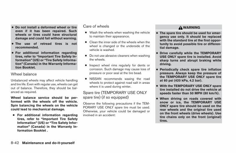
● Do not install a deformed wheel or tireeven if it has been repaired. Suchwheels or tires could have structuraldamage and could fail without warning.
● The use of retread tires is notrecommended.
● For additional information regardingtires, refer to “Important Tire Safety In-formation” (US) or “Tire Safety Informa-tion” (Canada) in the Warranty Informa-tion Booklet.
Wheel balance
Unbalanced wheels may affect vehicle handlingand tire life. Even with regular use, wheels can getout of balance. Therefore, they should be bal-anced as required.
Wheel balance service should be per-formed with the wheels off the vehicle.Spin balancing the wheels on the vehiclecould lead to mechanical damage.
● For additional information regardingtires, refer to “Important Tire SafetyInformation” (US) or “Tire Safety Infor-mation” (Canada) in the Warranty In-formation Booklet .
Care of wheels
● Wash the wheels when washing the vehicleto maintain their appearance.
● Clean the inner side of the wheels when thewheel is changed or the underside of thevehicle is washed.
● Do not use abrasive cleaners when washingthe wheels.
● Inspect wheel rims regularly for dents orcorrosion. Such damage may cause loss ofpressure or poor seal at the tire bead.
● NISSAN recommends waxing the roadwheels to protect against road salt in areaswhere it is used during winter.
Spare tire (TEMPORARY USE ONLYspare tire) (if so equipped)
Observe the following precautions if the TEM-PORARY USE ONLY spare tire must be used.Otherwise, your vehicle could be damaged orinvolved in an accident:
WARNING
● The spare tire should be used for emer-gency use only. It should be replacedwith the standard tire at the first oppor-tunity to avoid possible tire or differen-tial damage.
● Drive carefully while the TEMPORARYUSE ONLY spare tire is installed. Avoidsharp turns and abrupt braking whiledriving.
● Periodically check spare tire inflationpressure. Always keep the pressure ofthe TEMPORARY USE ONLY spare tireat 60 psi (420 kPa, 4.2 bar).
● With the TEMPORARY USE ONLY sparetire installed do not drive the vehicle atspeeds faster than 50 MPH (80 km/h).
● When driving on roads covered withsnow or ice, the TEMPORARY USEONLY spare tire should be used on therear wheels and the original tire usedon the front wheels (drive wheels). Usetire chains only on the front (original)tires.
8-42 Maintenance and do-it-yourself
Z REVIEW COPY:—2004 Maxima (max)Owners Manual (owners)—USA English (nna)10/20/03—arosenma X
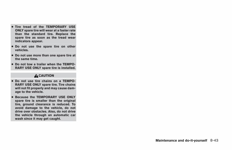
● Tire tread of the TEMPORARY USEONLY spare tire will wear at a faster ratethan the standard tire. Replace thespare tire as soon as the tread wearindicators appear.
● Do not use the spare tire on othervehicles.
● Do not use more than one spare tire atthe same time.
● Do not tow a trailer when the TEMPO-RARY USE ONLY spare tire is installed.
CAUTION
● Do not use tire chains on a TEMPO-RARY USE ONLY spare tire. Tire chainswill not fit properly and may cause dam-age to the vehicle.
● Because the TEMPORARY USE ONLYspare tire is smaller than the originaltire, ground clearance is reduced. Toavoid damage to the vehicle, do notdrive over obstacles. Also, do not drivethe vehicle through an automatic carwash since it may get caught.
Maintenance and do-it-yourself 8-43
Z REVIEW COPY:—2004 Maxima (max)Owners Manual (owners)—USA English (nna)10/20/03—arosenma X

8-44 Maintenance and do-it-yourself
MEMO
9 Technical and consumer information
Capacities and recommended fuel/lubricants . . . . . . . . . 9-2Fuel recommendation . . . . . . . . . . . . . . . . . . . . . . . . . . . 9-3Engine oil and oil filter recommendation . . . . . . . . . . . 9-5Recommended SAE viscosity number . . . . . . . . . . . . 9-6Air conditioner system refrigerant andlubricant recommendations . . . . . . . . . . . . . . . . . . . . . . 9-6
Specifications. . . . . . . . . . . . . . . . . . . . . . . . . . . . . . . . . . . . . 9-7Engine . . . . . . . . . . . . . . . . . . . . . . . . . . . . . . . . . . . . . . . . 9-7Wheels and tires . . . . . . . . . . . . . . . . . . . . . . . . . . . . . . . 9-8Dimensions and weights . . . . . . . . . . . . . . . . . . . . . . . . 9-8
When traveling or registering your vehicle inanother country . . . . . . . . . . . . . . . . . . . . . . . . . . . . . . . . . . . 9-9Vehicle identification . . . . . . . . . . . . . . . . . . . . . . . . . . . . . . . 9-9
Vehicle identification number (VIN) plate . . . . . . . . . . 9-9Vehicle identification number(chassis number) . . . . . . . . . . . . . . . . . . . . . . . . . . . . . . . 9-9Engine serial number. . . . . . . . . . . . . . . . . . . . . . . . . . . 9-10F.M.V.S.S. certification label . . . . . . . . . . . . . . . . . . . . 9-10Emission control information label . . . . . . . . . . . . . . . 9-10
Tire placard . . . . . . . . . . . . . . . . . . . . . . . . . . . . . . . . . . .9-11Air conditioner specification label. . . . . . . . . . . . . . . . 9-11
Installing front license plate . . . . . . . . . . . . . . . . . . . . . . . . 9-11Vehicle loading information . . . . . . . . . . . . . . . . . . . . . . . . 9-12
Terms . . . . . . . . . . . . . . . . . . . . . . . . . . . . . . . . . . . . . . . .9-12Determining vehicle load capacity . . . . . . . . . . . . . . . 9-12Loading tips . . . . . . . . . . . . . . . . . . . . . . . . . . . . . . . . . .9-13
Towing a trailer . . . . . . . . . . . . . . . . . . . . . . . . . . . . . . . . . . .9-13Maximum load limits . . . . . . . . . . . . . . . . . . . . . . . . . . . 9-13Towing load/specification chart . . . . . . . . . . . . . . . . . 9-15Towing safety . . . . . . . . . . . . . . . . . . . . . . . . . . . . . . . . .9-15Flat towing. . . . . . . . . . . . . . . . . . . . . . . . . . . . . . . . . . . .9-17
Uniform tire quality grading . . . . . . . . . . . . . . . . . . . . . . . . 9-17Emission control system warranty . . . . . . . . . . . . . . . . . . 9-18Reporting safety defects (US only) . . . . . . . . . . . . . . . . . 9-19Readiness for inspection/maintenance (I/M) test . . . . . 9-19Owner’s Manual/Service Manual order information . . . 9-20
In the event of a collision . . . . . . . . . . . . . . . . . . . . . . . 9-21
Z REVIEW COPY:—2004 Maxima (max)Owners Manual (owners)—USA English (nna)10/20/03—arosenma X
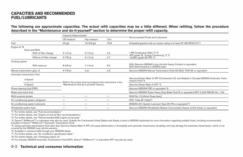
The following are approximate capacities. The actual refill capacities may be a little different. When refilling, follow the proceduredescribed in the “Maintenance and do-it-yourself” section to determine the proper refill capacity.
Capacity (Approximate)Recommended Fluids and Lubricants
US measure Imp measure Liter
Fuel 20 gal 16-5/8 gal 75.8 Unleaded gasoline with an octane rating of at least 87 AKI (RON 91)*1
Engine oil *8Drain and Refill
With oil filter change 4-1/4 qt 3-1/2 qt 4.0 • API Certification Mark *2 *3•API grade SL, Energy Conserving *2 *3• ILSAC grade GF-III*2 *3Without oil filter change 3-7/8 qt 3-1/4 qt 3.7
Cooling system
With reservoir 8-5/8 qt 7-1/4 qt 8.2 50% Genuine NISSAN Long Life Anti-freeze Coolant or equivalent50% Demineralized or distilled water
Manual transmission gear oil 4-7/8 pt 4 pt 2.3 Genuine NISSAN Manual Transmission Fluid HQ Multi 75W-85 or equivalent
Automatic transmission fluid
Refill to the proper level according to the instructions in the“Maintenance and do-it-yourself” section.
4 Speed Genuine Nissan Matic D ATF (Continental U.S. and Alaska) or Canada NISSAN Automatic Trans-mission Fluid.*4
5 Speed Genuine Nissan Matic K ATF *5
Power steering fluid (PSF) Genuine NISSAN PSF or equivalent.*9
Brake and clutch fluid Genuine NISSAN Super Heavy Duty Brake Fluid*6 or equivalent DOT 3 (US FMVSS No. 116)
Multi-purpose grease — — — NLGI No. 2 (Lithium Soap base)
Air conditioning system refrigerant — — — HFC-134a (R-134a)*7
Air conditioning system lubricants — — — NISSAN A/C System Lubricant Type DH-PS or equivalent*7
Windshield washer fluid — — — Genuine NISSAN Windshield Washer Concentrate Cleaner & Anti-freeze or equivalent
*1: For further details, see “Fuel recommendation.”*2: For further details, see “Engine oil and oil filter recommendations.”*3: For further details, see “Recommended SAE engine oil viscosity.”*4: Dexron™ III/Mercon™ or equivalent may also be used. Outside the Continental United States and Alaska contact a NISSAN dealership for more information regarding suitable fluids, including recommendedbrand(s) of Dexron™ III/Mercon™ Automatic Transmission Fluid.*5: Using automatic transmission fluid other than Genuine Nissan Matic K ATF will cause deterioration in driveability and automatic transmission durability, and may damage the automatic transmission, which is notcovered by the NISSAN new vehicle warranty.*6: Available in mainland USA through your NISSAN dealer.*7: For further details, see “Air conditioner specification label.”*8: For further details, see “Changing engine oil.”*9: For Canada, NISSAN Automatic Transmission Fluid (ATF), Dexron™ III/Mercon™, or equivalent ATF may also be used.
CAPACITIES AND RECOMMENDEDFUEL/LUBRICANTS
9-2 Technical and consumer information
Z REVIEW COPY:—2004 Maxima (max)Owners Manual (owners)—USA English (nna)10/20/03—arosenma X
FUEL RECOMMENDATION
Use unleaded regular gasoline with an octanerating of at least 87 AKI (Anti-Knock Index) num-ber (Research octane number 91).
For improved vehicle performance, NISSAN rec-ommends the use of unleaded premium gasolinewith an octane rating of at least 91 AKI number(Research octane number 96).
CAUTION
● Using a fuel other than that specifiedcould adversely affect the emissioncontrol system, and may also affect thewarranty coverage.
● Under no circumstances should aleaded gasoline be used, because thiswill damage the three-way catalyst.
Reformulated gasoline
Some fuel suppliers are now producing reformu-lated gasolines. These gasolines are speciallydesigned to reduce vehicle emissions. NISSANsupports efforts towards cleaner air and sug-gests that you use reformulated gasoline whenavailable.
Gasoline containing oxygenates
Some fuel suppliers sell gasoline containing oxy-genates such as ethanol, MTBE and methanolwith or without advertising their presence.NISSAN does not recommend the use of fuels ofwhich the oxygenate content and the fuel com-patibility for your NISSAN cannot be readily de-termined. If in doubt, ask your service stationmanager.
If you use oxygenate-blend gasoline, please takethe following precautions as the usage of suchfuels may cause vehicle performance problemsand/or fuel system damage.
● The fuel should be unleaded and havean octane rating no lower than thatrecommended for unleaded gasoline.
● If an oxygenate-blend other thanmethanol blend is used, it should con-tain no more than 10% oxygenate.(MTBE may, however, be added up to15%.)
● If a methanol blend is used, it shouldcontain no more than 5% methanol(methyl alcohol, wood alcohol). Itshould also contain a suitable amountof appropriate cosolvents and corro-sion inhibitors. If not properly formu-lated with appropriate cosolvents and
corrosion inhibitors, such methanolblends may cause fuel system damageand/or vehicle performance problems.At this time, sufficient data is not avail-able to ensure that all methanol blendsare suitable for use in NISSAN ve-hicles.
If any driveability problems such as engine stall-ing and difficult hot-starting are experienced afterusing oxygenate-blend fuels, immediatelychange to a non-oxygenate fuel or a fuel with alow blend of MTBE.
Take care not to spill gasoline during refu-eling. Gasoline containing oxygenates cancause paint damage.
Aftermarket fuel additives
NISSAN does not recommend the use of anyaftermarket fuel additives (for example, fuel injec-tor cleaner, octane booster, intake valve depositremovers, etc.) which are sold commercially.Many of these additives intended for gum, varnishor deposit removal may contain active solvents orsimilar ingredients that can be harmful to the fuelsystem and engine.
Octane rating tipsIn most parts of North America, you should useunleaded gasoline with an octane rating of at
Technical and consumer information 9-3
Z REVIEW COPY:—2004 Maxima (max)Owners Manual (owners)—USA English (nna)10/20/03—arosenma X
least 87 AKI (Anti-Knock Index) number. How-ever, you may use unleaded gasoline with anoctane rating as low as 85 AKI (Anti-Knock Index)number in high altitude areas [over 4,000 ft(1,219 m)] such as: Colorado, Montana, NewMexico, Utah, Wyoming, northeastern Nevada,southern Idaho, western South Dakota, westernNebraska, and the part of Texas which is directlysouth of New Mexico.
Using unleaded gasoline with an octanerating lower than stated above can causepersistent, heavy “spark knock.” (“Sparkknock” is a metallic rapping noise.) If se-vere, this can lead to engine damage. If youdetect a persistent heavy spark knock evenwhen using gasoline of the stated octanerating, or if you hear steady spark knockwhile holding a steady speed on levelroads, have a NISSAN dealer correct thecondition. Failure to correct the conditionis misuse of the vehicle, for which NISSANis not responsible.
Incorrect ignition timing may result in sparkknock, after-run and/or overheating, which maycause excessive fuel consumption or enginedamage. If any of the above symptoms are en-countered, have your vehicle checked at aNISSAN dealer.
However, now and then you may noticelight spark knock for a short time whileaccelerating or driving up hills. This is not acause for concern, because you get thegreatest fuel benefit when there is lightspark knock for a short time under heavyengine load.
9-4 Technical and consumer information
Z REVIEW COPY:—2004 Maxima (max)Owners Manual (owners)—USA English (nna)10/20/03—arosenma X
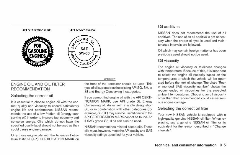
ENGINE OIL AND OIL FILTERRECOMMENDATION
Selecting the correct oil
It is essential to choose engine oil with the cor-rect quality and viscosity to ensure satisfactoryengine life and performance. NISSAN recom-mends the use of a low friction oil (energy con-serving oil) in order to improve fuel economy andconserve energy. Oils which do not have thespecified quality label should not be used as theycould cause engine damage.
Only those engine oils with the American Petro-leum Institute (API) CERTIFICATION MARK on
the front of the container should be used. Thistype of oil supersedes the existing API SG, SH, orSJ and Energy Conserving II categories.
If you cannot find engine oil with the API CERTI-FICATION MARK, use API grade SL EnergyConserving oil. An oil with a single designationSL, or in combination with other categories (forexample, SL/CF) may also be used if one with theAPI CERTIFICATION MARK cannot be found. AnILSAC grade GF-III oil can also be used.
NISSAN recommends mineral based oils. Theseoils must, however, meet the API quality and SAEviscosity ratings specified for your vehicle.
Oil additives
NISSAN does not recommend the use of oiladditives. The use of an oil additive is not neces-sary when the proper oil type is used and main-tenance intervals are followed.
Oil which may contain foreign matter or has beenpreviously used should not be used.
Oil viscosity
The engine oil viscosity or thickness changeswith temperature. Because of this, it is importantto select the engine oil viscosity based on thetemperatures at which the vehicle will be oper-ated before the next oil change. The chart “Rec-ommended SAE viscosity number” shows therecommended oil viscosities for the expectedambient temperatures. Choosing an oil viscosityother than that recommended could cause seri-ous engine damage.
Selecting the correct oil filter
Your new NISSAN vehicle is equipped with ahigh-quality genuine NISSAN oil filter. When re-placing, use a genuine NISSAN oil filter or itsequivalent for the reason described in “Changeintervals”.
WTI0082
Technical and consumer information 9-5
Z REVIEW COPY:—2004 Maxima (max)Owners Manual (owners)—USA English (nna)10/20/03—arosenma X
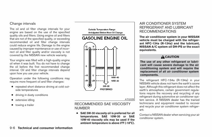
Change intervalsThe oil and oil filter change intervals for yourengine are based on the use of the specifiedquality oils and filters. Using engine oil and filtersthat are not of the specified quality, or exceedingrecommended oil and filter change intervalscould reduce engine life. Damage to the enginecaused by improper maintenance or use of incor-rect oil and filter quality and/or viscosity is notcovered by the NISSAN new vehicle warranty.
Your engine was filled with a high-quality engineoil when it was built. You do not have to changethe oil before the first recommended changeinterval. Oil and filter change intervals dependupon how you use your vehicle.
Operation under the following conditions mayrequire more frequent oil and filter changes:
● repeated short distance driving at cold out-side temperatures
● driving in dusty conditions
● extensive idling
● towing a trailer RECOMMENDED SAE VISCOSITYNUMBER
● SAE 5W-30 viscosity oil is preferred for alltemperatures. SAE 10W-30 or SAE10W-40 viscosity oils may be used if theambient temperature is above 0°F (-18°C).
AIR CONDITIONER SYSTEMREFRIGERANT AND LUBRICANTRECOMMENDATIONSThe air conditioner system in your NISSANvehicle must be charged with the refriger-ant HFC-134a (R-134a) and the lubricant,NISSAN A/C system oil DH-PS or the exactequivalents.
CAUTION
The use of any other refrigerant or lubri-cant will cause severe damage to the airconditioning system and will require thereplacement of all air conditioner systemcomponents.
The refrigerant HFC-134a (R-134a) in yourNISSAN vehicle does not harm the earth’s ozonelayer. Although this refrigerant does not affect theearth’s atmosphere, certain government regula-tions require the recovery and recycling of anyrefrigerant during automotive air conditioner sys-tem service. A NISSAN dealer has the trainedtechnicians and equipment needed to recoverand recycle your air conditioner system refriger-ant.
Contact a NISSAN dealer when servicing your airconditioner system.
ATI1028
9-6 Technical and consumer information
Z REVIEW COPY:—2004 Maxima (max)Owners Manual (owners)—USA English (nna)10/20/03—arosenma X
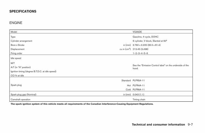
ENGINE
Model VQ35DE
Type Gasoline, 4-cycle, DOHC
Cylinder arrangement 6-cylinder, V-block, Slanted at 60°
Bore x Stroke in (mm) 3.760 x 3.205 (95.5 x 81.4)
Displacement cu in (cm3) 213.45 (3,498)
Firing order 1–2–3–4–5–6
Idle speed
See the “Emission Control label” on the underside of thehood.
M/T
A/T (in “N” position)
Ignition timing (degree B.T.D.C. at idle speed)
CO % at idle
Spark plug
Standard PLFR5A-11
Hot PLFR4A-11
Cold PLFR6A-11
Spark plug gap (Nominal) in (mm) 0.043 (1.1)
Camshaft operation Timing chain
The spark ignition system of this vehicle meets all requirements of the Canadian Interference-Causing Equipment Regulations.
SPECIFICATIONS
Technical and consumer information 9-7
Z REVIEW COPY:—2004 Maxima (max)Owners Manual (owners)—USA English (nna)10/20/03—arosenma X
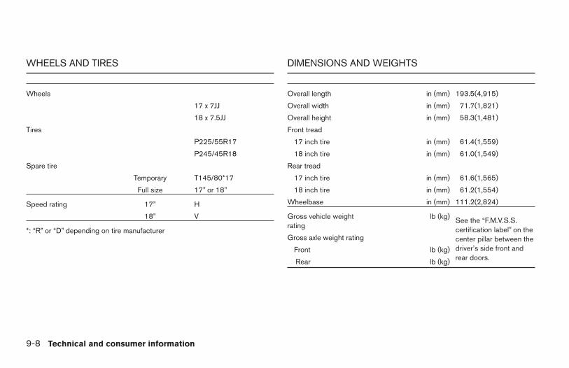
WHEELS AND TIRES
Wheels
17 x 7JJ
18 x 7.5JJ
Tires
P225/55R17
P245/45R18
Spare tire
Temporary T145/80*17
Full size 17” or 18”
Speed rating 17” H
18” V
*: “R” or “D” depending on tire manufacturer
DIMENSIONS AND WEIGHTS
Overall length in (mm) 193.5(4,915)
Overall width in (mm) 71.7(1,821)
Overall height in (mm) 58.3(1,481)
Front tread
17 inch tire in (mm) 61.4(1,559)
18 inch tire in (mm) 61.0(1,549)
Rear tread
17 inch tire in (mm) 61.6(1,565)
18 inch tire in (mm) 61.2(1,554)
Wheelbase in (mm) 111.2(2,824)
Gross vehicle weightrating
lb (kg) See the “F.M.V.S.S.certification label” on thecenter pillar between thedriver’s side front andrear doors.
Gross axle weight rating
Front lb (kg)
Rear lb (kg)
9-8 Technical and consumer information
Z REVIEW COPY:—2004 Maxima (max)Owners Manual (owners)—USA English (nna)10/20/03—arosenma X
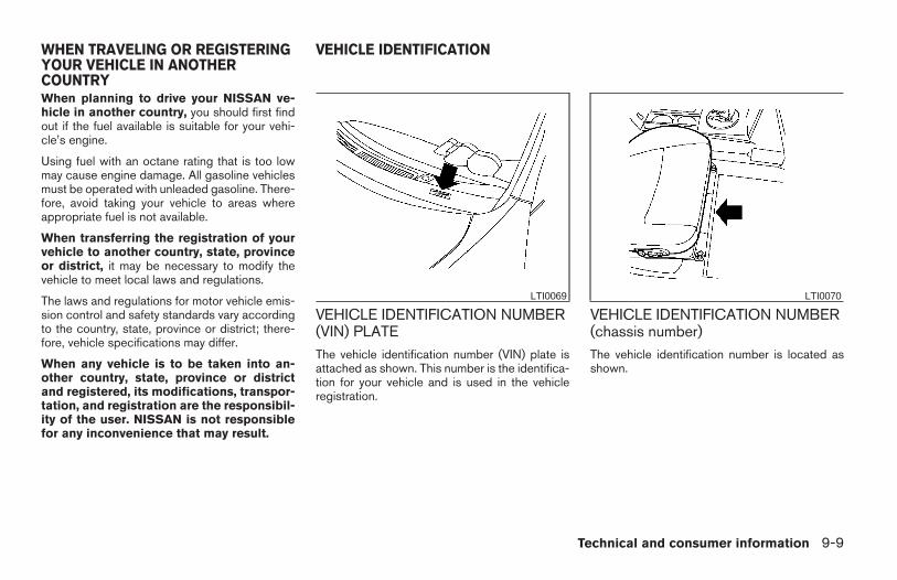
When planning to drive your NISSAN ve-hicle in another country, you should first findout if the fuel available is suitable for your vehi-cle’s engine.
Using fuel with an octane rating that is too lowmay cause engine damage. All gasoline vehiclesmust be operated with unleaded gasoline. There-fore, avoid taking your vehicle to areas whereappropriate fuel is not available.
When transferring the registration of yourvehicle to another country, state, provinceor district, it may be necessary to modify thevehicle to meet local laws and regulations.
The laws and regulations for motor vehicle emis-sion control and safety standards vary accordingto the country, state, province or district; there-fore, vehicle specifications may differ.
When any vehicle is to be taken into an-other country, state, province or districtand registered, its modifications, transpor-tation, and registration are the responsibil-ity of the user. NISSAN is not responsiblefor any inconvenience that may result.
VEHICLE IDENTIFICATION NUMBER(VIN) PLATEThe vehicle identification number (VIN) plate isattached as shown. This number is the identifica-tion for your vehicle and is used in the vehicleregistration.
VEHICLE IDENTIFICATION NUMBER(chassis number)The vehicle identification number is located asshown.
LTI0069 LTI0070
WHEN TRAVELING OR REGISTERINGYOUR VEHICLE IN ANOTHERCOUNTRY
VEHICLE IDENTIFICATION
Technical and consumer information 9-9
Z REVIEW COPY:—2004 Maxima (max)Owners Manual (owners)—USA English (nna)10/20/03—arosenma X
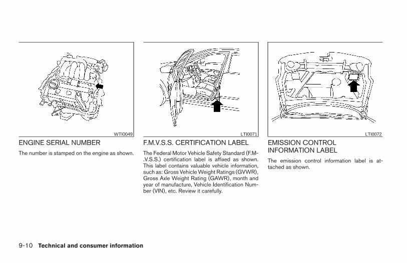
ENGINE SERIAL NUMBERThe number is stamped on the engine as shown.
F.M.V.S.S. CERTIFICATION LABELThe Federal Motor Vehicle Safety Standard (F.M-.V.S.S.) certification label is affixed as shown.This label contains valuable vehicle information,such as: Gross Vehicle Weight Ratings (GVWR),Gross Axle Weight Rating (GAWR), month andyear of manufacture, Vehicle Identification Num-ber (VIN), etc. Review it carefully.
EMISSION CONTROLINFORMATION LABELThe emission control information label is at-tached as shown.
WTI0049 LTI0071 LTI0072
9-10 Technical and consumer information
Z REVIEW COPY:—2004 Maxima (max)Owners Manual (owners)—USA English (nna)10/20/03—arosenma X
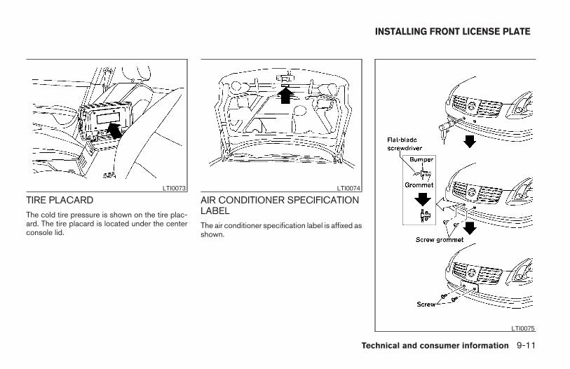
TIRE PLACARDThe cold tire pressure is shown on the tire plac-ard. The tire placard is located under the centerconsole lid.
AIR CONDITIONER SPECIFICATIONLABELThe air conditioner specification label is affixed asshown.
LTI0073 LTI0074
LTI0075
INSTALLING FRONT LICENSE PLATE
Technical and consumer information 9-11
Z REVIEW COPY:—2004 Maxima (max)Owners Manual (owners)—USA English (nna)10/20/03—arosenma X
Use the following steps to mount the front licenseplate:
Before mounting the license plate, confirm thatthe following parts are enclosed in the plasticbag:
● License plate bracket
● License plate bracket screws x 2
● License plate screws x 2
● Screw grommets x 2
1. Make a shallow hole in the bumper fascia atthe location marks (small dimples) using a0.39 in (10 mm) drill. To avoid damaging thearea behind the fascia, apply only light pres-sure to the drill.
2. Insert the grommets into the holes in thebumper fascia.
3. Insert a small flat-bladed screwdriver intothe grommet hole to turn the threaded part ofthe grommet 90°.
4. Mount the license plate bracket using thetwo longer screws.
5. Use the two shorter hex head screws tomount the license plate to the license platebracket.
WARNING
● It is extremely dangerous to ride in acargo area inside a vehicle. In a colli-sion, people riding in these areas aremore likely to be seriously injured orkilled.
● Do not allow people to ride in any areaof your vehicle that is not equipped withseats and seat belts.
● Be sure everyone in your vehicle is in aseat and using a seat belt properly.
TERMS
It is important to familiarize yourself with the fol-lowing terms before loading your vehicle:
● Curb Weight (actual weight of your vehicle)- vehicle weight including: standard and op-tional equipment, fluids, emergency tools,and spare tire assembly. This weight doesnot include passengers and cargo.
● GVW (Gross Vehicle Weight) - curb weightplus the combined weight of passengersand cargo.
● GVWR (Gross Vehicle Weight Rating) -maximum total weight (load) limit specifiedfor the vehicle.
● GAWR (Gross Axle Weight Rating) - maxi-mum weight (load) limit specified for thefront or rear axle.
DETERMINING VEHICLE LOADCAPACITY
The load capacity of this vehicle is determined byweight, not by available cargo space. For ex-ample, a luggage rack, bike carrier, cartop carrieror similar equipment does not increase load car-rying capacity of your vehicle.
To determine vehicle load capacity:
Vehicle weight can be determined by using acommercial-grade scale, found at places such asa truck stop, gravel quarry, grain elevator, or ascrap metal recycling facility.
1. Determine the curb weight of your vehicle.
2. Compare the curb weight amount to theGVWR specified for your vehicle to deter-mine how much more weight your vehiclecan carry.
VEHICLE LOADING INFORMATION
9-12 Technical and consumer information
Z REVIEW COPY:—2004 Maxima (max)Owners Manual (owners)—USA English (nna)10/20/03—arosenma X
3. After loading (cargo and passengers), re-weigh your vehicle to determine if eitherGVWR or GAWR for your vehicle is ex-ceeded. If GVWR is exceeded, removecargo as necessary. If either the front or rearGAWR is exceeded, shift the load or removecargo as necessary.
LOADING TIPS
● The GVW must not exceed GVWR orGAWR as specified on the F.M.V.S.S. certi-fication label.
● Do not load the front and rear axle to theGAWR. Doing so will exceed the GVWR.
WARNING
● Properly secure all cargo with ropes orstraps to help prevent it from sliding orshifting. Do not place cargo higher thanthe seatbacks. In a sudden stop or col-lision, unsecured cargo could causepersonal injury.
● Do not load your vehicle any heavierthan the GVWR or the maximum frontand rear GAWRs. If you do, parts of yourvehicle can break, tire damage couldoccur, or it can change the way yourvehicle handles. This could result inloss of control and cause personalinjury.
● Overloading not only can shorten thelife of your vehicle and the tire, but canalso cause unsafe vehicle handling andlonger braking distances. This maycause a premature tire failure whichcould result in a serious accident andpersonal injury. Failures caused byoverloading are not covered by the ve-hicle’s warranty.
Your new vehicle was designed to be used pri-marily to carry passengers and cargo. Rememberthat towing a trailer places additional loads onyour vehicle’s engine, drive train, steering, brak-ing and other systems.
A Nissan Trailer Towing Guide (U.S. only) isavailable from a NISSAN dealer. This guide in-cludes information on trailer towing ability and thespecial equipment required for proper towing.
MAXIMUM LOAD LIMITS
Maximum trailer loads
Never allow the total trailer load to exceed thevalue specified in the Towing Load/SpecificationChart found later in this section. The total trailerload equals trailer weight plus its cargo weight.Towing loads greater than specified or usingimproper towing equipment could adversely af-fect vehicle handling, braking and performance.
The ability of your vehicle to tow a trailer is notonly related to the maximum trailer loads, but alsothe places you plan to tow. Tow weights appro-priate for level highway driving may have to bereduced on very steep grades or in low tractionsituations (for example, on slippery boat ramps).
TOWING A TRAILER
Technical and consumer information 9-13
Z REVIEW COPY:—2004 Maxima (max)Owners Manual (owners)—USA English (nna)10/20/03—arosenma X
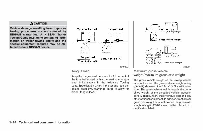
CAUTION
Vehicle damage resulting from impropertowing procedures are not covered byNISSAN warranties. A NISSAN TrailerTowing Guide (U.S. only) containing infor-mation on trailer towing ability and thespecial equipment required may be ob-tained from a NISSAN dealer.
Tongue loadKeep the tongue load between 9 - 11 percent ofthe total trailer load within the maximum tongueload limits shown in the following TowingLoad/Specification Chart. If the tongue load be-comes excessive, rearrange cargo to allow forproper tongue load.
Maximum gross vehicleweight/maximum gross axle weightThe gross vehicle weight of the towing vehiclemust not exceed the gross vehicle weight rating(GVWR) shown on the F. M. V. S. S. certificationlabel. The gross vehicle weight equals the com-bined weight of the unloaded vehicle, passen-gers, luggage, hitch, trailer tongue load and anyother optional equipment. In addition, front or reargross axle weight must not exceed the gross axleweight rating (GAWR) shown on the F. M. V. S. S.certification label.
CA0009 TI1012M
9-14 Technical and consumer information
Z REVIEW COPY:—2004 Maxima (max)Owners Manual (owners)—USA English (nna)10/20/03—arosenma X
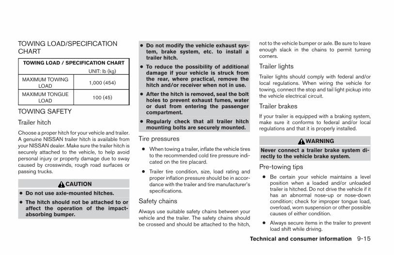
TOWING LOAD/SPECIFICATIONCHART
TOWING LOAD / SPECIFICATION CHART
UNIT: lb (kg)
MAXIMUM TOWINGLOAD
1,000 (454)
MAXIMUM TONGUELOAD
100 (45)
TOWING SAFETY
Trailer hitch
Choose a proper hitch for your vehicle and trailer.A genuine NISSAN trailer hitch is available fromyour NISSAN dealer. Make sure the trailer hitch issecurely attached to the vehicle, to help avoidpersonal injury or property damage due to swaycaused by crosswinds, rough road surfaces orpassing trucks.
CAUTION
● Do not use axle-mounted hitches.
● The hitch should not be attached to oraffect the operation of the impact-absorbing bumper.
● Do not modify the vehicle exhaust sys-tem, brake system, etc. to install atrailer hitch.
● To reduce the possibility of additionaldamage if your vehicle is struck fromthe rear, where practical, remove thehitch and/or receiver when not in use.
● After the hitch is removed, seal the boltholes to prevent exhaust fumes, wateror dust from entering the passengercompartment.
● Regularly check that all trailer hitchmounting bolts are securely mounted.
Tire pressures
● When towing a trailer, inflate the vehicle tiresto the recommended cold tire pressure indi-cated on the tire placard.
● Trailer tire condition, size, load rating andproper inflation pressure should be in accor-dance with the trailer and tire manufacturer’sspecifications.
Safety chains
Always use suitable safety chains between yourvehicle and the trailer. The safety chains shouldbe crossed and should be attached to the hitch,
not to the vehicle bumper or axle. Be sure to leaveenough slack in the chains to permit turningcorners.
Trailer lights
Trailer lights should comply with federal and/orlocal regulations. When wiring the vehicle fortowing, connect the stop and tail light pickup intothe vehicle electrical circuit.
Trailer brakesIf your trailer is equipped with a braking system,make sure it conforms to federal and/or localregulations and that it is properly installed.
WARNING
Never connect a trailer brake system di-rectly to the vehicle brake system.
Pre-towing tips● Be certain your vehicle maintains a level
position when a loaded and/or unloadedtrailer is hitched. Do not drive the vehicle if ithas an abnormal nose-up or nose-downcondition; check for improper tongue load,overload, worn suspension or other possiblecauses of either condition.
● Always secure items in the trailer to preventload shift while driving.
Technical and consumer information 9-15
Z REVIEW COPY:—2004 Maxima (max)Owners Manual (owners)—USA English (nna)10/20/03—arosenma X
● Be certain your rearview mirrors conform toall federal, state or local regulations. If not,install any mirrors required for towing beforedriving the vehicle.
Trailer towing tips
In order to gain skill and an understanding of thevehicle’s behavior, you should practice turning,stopping and backing up in an area which is freefrom traffic. Steering stability and braking perfor-mance will be somewhat different than undernormal driving conditions.
● Always secure items in the trailer to preventload shift while driving.
● Avoid abrupt starts, acceleration or stops.
● Avoid sharp turns or lane changes.
● Always drive your vehicle at a moderatespeed.
● Always block the wheels on both vehicle andtrailer when parking. Parking on a slope isnot recommended; however, if you must doso, and if your vehicle is equipped with anautomatic transmission, first block thewheels and apply the parking brake, andthen move the transmission shift selectorlever into the P (Park) position. If you movethe shift selector lever to the P (Park) posi-tion before blocking the wheels and applying
the parking brake, transmission damagecould occur.
● When going down a hill, shift into a lowergear and use the engine braking effect.When going up a long grade, downshift thetransmission to a lower gear and reducespeed to reduce chances of engine over-loading and/or overheating. However, forlong steep grades, do not stay in 1st or 2ndgear when driving above 35 MPH (56 km/h).
● If the engine coolant rises to an extremelyhigh temperature when the air conditionersystem is on, turn off the air conditioner.Coolant heat can be additionally vented byopening the windows, switching the fancontrol to high and setting the temperaturecontrol to the HOT position.
● Trailer towing requires more fuel than normalcircumstances.
● Avoid towing a trailer for your vehicle’s first500 miles (805 km).
● Have your vehicle serviced more often thanat intervals specified in the recommendedMaintenance Schedule in the “NISSAN Ser-vice and Maintenance Guide”.
● When making a turn, your trailer wheels willbe closer to the inside of the turn than yourvehicle wheels. To compensate for this,
make a larger than normal turning radiusduring the turn.
● Crosswinds and rough roads will adverselyaffect vehicle/trailer handling, possibly caus-ing vehicle sway. When being passed bylarger vehicles, be prepared for possiblechanges in crosswinds that could affect ve-hicle handling. If swaying does occur, firmlygrip the steering wheel, steer straight ahead,and immediately (but gradually) reduce ve-hicle speed. This combination will help sta-bilize the vehicle. Never increase speed.
● Be careful when passing other vehicles.Passing while towing a trailer requires con-siderably more distance than normal pass-ing. Remember, the length of the trailer mustalso pass the other vehicle before you cansafely change lanes.
● To maintain engine braking efficiency andelectrical charging performance, do not use5th gear (manual transmission) or overdrive(automatic transmission).
● Avoid holding the brake pedal down too longor too frequently. This could cause thebrakes to overheat, resulting in reducedbraking efficiency.
When towing a trailer, transmissionoil/fluid should be changed more fre-
9-16 Technical and consumer information
Z REVIEW COPY:—2004 Maxima (max)Owners Manual (owners)—USA English (nna)10/20/03—arosenma X
quently. For additional information, see the“Maintenance and do-it-yourself” sectionearlier in this manual.
FLAT TOWING
Towing your vehicle with all four wheels on theground is sometimes called flat towing. Thismethod is sometimes used when towing a vehiclebehind a recreational vehicle, such as a motorhome.
CAUTION
● Failure to follow these guidelines canresult in severe transmission damage.
● Whenever flat towing your vehicle, al-ways tow forward, never backward.
● DO NOT tow any automatic transmis-sion vehicle with all four wheels on theground (flat towing). Doing so WILLDAMAGE internal transmission partsdue to lack of transmission lubrication.
● For emergency towing procedures referto “Towing recommended by NISSAN”in the “In case of emergency” section ofthis manual.
Automatic TransmissionTo tow a vehicle equipped with an automatictransmission, an appropriate vehicle dolly MUSTbe placed under the towed vehicle’s drivewheels. Always follow the dolly manufacturer’srecommendations when using their product.
Manual Transmission● Always tow with the manual transmission in
Neutral.
● After towing 500 miles, start and idle theengine with the transmission in Neutral fortwo minutes. Failure to idle the engine afterevery 500 miles of towing may cause dam-age to internal transmission parts.
DOT (Department of Transportation) QualityGrades: All passenger car tires must conform tofederal safety requirements in addition to thesegrades.
Quality grades can be found where applicable onthe tire sidewall between tread shoulder andmaximum section width. For example:
Treadwear 200 Traction AA Temperature A
Treadwear
Treadwear grade is a comparative rating basedon tire wear rate when tested under controlledconditions on specified government test courses.For example, a tire graded 150 would wear oneand a half (1-1/2) times as well on the govern-ment course as a tire graded 100. However,relative tire performance depends on actual driv-ing conditions, and may vary significantly due tovariations in driving habits, service practices anddifferences in road characteristics and climate.
Traction AA, A, B and C
The traction grades, from highest to lowest, areAA, A, B, and C. Those grades represent thetire’s ability to stop on wet pavement as mea-sured under controlled conditions on specifiedgovernment test surfaces of asphalt and con-crete. A tire marked C may have poor tractionperformance.
UNIFORM TIRE QUALITY GRADING
Technical and consumer information 9-17
Z REVIEW COPY:—2004 Maxima (max)Owners Manual (owners)—USA English (nna)10/20/03—arosenma X
WARNING
The traction grade assigned to your ve-hicle tires is based on straight-aheadbraking traction tests and does not in-clude acceleration, cornering, hydroplan-ing or peak traction characteristics.
Temperature A, B and C
Temperature grades are A (the highest), B, andC. They represent a tire’s resistance to heatbuild-up, and its ability to dissipate heat whentested under controlled conditions on a specifiedindoor laboratory test wheel. Sustained high tem-perature can cause tire material to degenerate,reducing tire life. Excessive temperatures canlead to sudden tire failure. Grade C correspondsto a performance level which all passenger cartires must meet under the Federal Motor VehicleSafety Standard No. 109. Grades A and B rep-resent higher levels of performance on laboratorytest wheels than the minimum required by law.
WARNING
The temperature grade for this tire is es-tablished for a tire that is properly inflatedand not overloaded. Excessive speed,under-inflation, or excessive loading, ei-ther separately or in combination, cancause heat build-up and possible tirefailure.
Your NISSAN vehicle is covered by the followingemission warranties:
For USA
1. Emission Defects Warranty
2. Emissions Performance Warranty
Details of these warranties may be found withother vehicle warranties in your Warranty Infor-mation Booklet which comes with your NISSANvehicle. If you did not receive a Warranty Informa-tion Booklet, or it is lost, you may obtain a re-placement by writing to:
● Nissan North America, Inc.Consumer Affairs DepartmentP.O. Box 191Gardena, CA 90248-0191
For Canada
Emission Control System Warranty
Details of these warranties may be found withother vehicle warranties in your Warranty Infor-mation Booklet which comes with your NISSANvehicle. If you did not receive a Warranty Informa-tion Booklet, or it is lost, you may obtain a re-placement by writing to:
● Nissan Canada Inc.5290 Orbitor DriveMississauga, Ontario, L4W 4Z5
EMISSION CONTROL SYSTEMWARRANTY
9-18 Technical and consumer information
Z REVIEW COPY:—2004 Maxima (max)Owners Manual (owners)—USA English (nna)10/20/03—arosenma X
If you believe that your vehicle has a defect whichcould cause a crash or could cause injury ordeath, you should immediately inform the Na-tional Highway Traffic Safety Administration(NHTSA) in addition to notifying NISSAN.
If NHTSA receives similar complaints, it mayopen an investigation, and if it finds that a safetydefect exists in a group of vehicles, it may order arecall and remedy campaign. However, NHTSAcannot become involved in individual problemsbetween you, your dealer, or NISSAN.
To contact NHTSA, you may call the Auto SafetyHotline toll-free at 1-888-327-4236. You mayalso write to: NHTSA, U.S. Department of Trans-portation, Washington, D.C. 20590. You can alsoobtain other information about motor vehiclesafety from the Hotline.
You may notify NISSAN by contacting our Con-sumer Affairs Department, toll-free, at 1-800-NISSAN-1.
In Hawaii call 1-808-836-0888.
Due to legal requirements in some states andCanadian Provinces, your vehicle may be re-quired to be in what is called the “ready condi-tion” for an Inspection/Maintenance (I/M) test ofthe emission control system.
The vehicle is set to the “ready condition” when itis driven through certain driving patterns. Usually,the ready condition can be obtained by ordinaryusage of the vehicle.
If a powertrain system component is repaired orthe battery is disconnected, the vehicle may bereset to a “not ready” condition. Before taking theI/M test, drive the vehicle through the followingpattern to set the vehicle to the ready condition. Ifyou cannot or do not want to perform the drivingpattern, a NISSAN dealer can conduct it for you.
WARNING
Always drive the vehicle in a safe andprudent manner according to traffic con-ditions and obey all traffic laws.
1. Start the engine when the engine coolanttemperature gauge needle points to C. Al-low the engine to idle until the gauge needlepoints between the C and H (normal oper-ating temperature).
2. Accelerate the vehicle to 55 MPH (88km/h), then quickly release the acceleratorpedal completely and keep it released for atleast 6 seconds.
3. Quickly depress the accelerator pedal for amoment, then drive the vehicle at a speed of53 - 60 MPH (86 - 96 km/h) for at least 5minutes.
4. Stop the vehicle.
5. Accelerate the vehicle to 35 MPH (55 km/h)and maintain the speed for 20 seconds.
6. Repeat steps 4 through 5 at least threetimes.
7. Accelerate the vehicle to 55 MPH (88 km/h)and maintain the speed for at least 3 min-utes.
8. Stop the vehicle. Place the transmission se-lector lever in the P (Park) or N (Neutral)position.
9. Turn the engine off.
10. Repeat steps 1 - 8 at least one more time.
If steps 1 through 7 are interrupted, repeat thepreceding step. Any safe driving mode is accept-able between steps. Do not stop the engine untilstep 7 is completed.
REPORTING SAFETY DEFECTS (USonly)
READINESS FOR INSPECTION/MAINTENANCE (I/M) TEST
Technical and consumer information 9-19
Z REVIEW COPY:—2004 Maxima (max)Owners Manual (owners)—USA English (nna)10/20/03—arosenma X
A genuine NISSAN Service Manual is the bestsource of service and repair information for yourvehicle. Filled with wiring diagrams, illustrationsand step-by-step diagnostic and adjustment pro-cedures, this manual is the same one used by thefactory trained technicians working at NISSANdealerships. Also available are genuine NISSANOwner’s Manuals, and genuine NISSAN Serviceand Owner’s Manuals for older NISSAN models.
For USA
For current pricing and availability of genuineNISSAN Service Manuals for the 2000 modelyear and later contact:
Tweddle Litho Company1-800-639-8841www.nissan-techinfo.com
For current pricing and availability of genuineNISSAN Service Manuals for the 1999 modelyear and prior, see a NISSAN dealer, or contact:
DDS Distribution Service, Ltd.20770 Westwood RoadStrongsville, OH 441361-800-247-5321
OWNER’S MANUAL/SERVICEMANUAL ORDER INFORMATION
9-20 Technical and consumer information
Z REVIEW COPY:—2004 Maxima (max)Owners Manual (owners)—USA English (nna)10/20/03—arosenma X
For current pricing and availability of genuineNISSAN Owner’s Manuals for the 2004 modelyear and prior, see a NISSAN dealer, or contact:
DDS Distribution Service, Ltd.20770 Westwood RoadStrongsville, OH 441361-800-247-5321
For Canada
To purchase a copy of a genuine NISSAN Ser-vice Manual or Owner’s Manual please contactyour nearest NISSAN dealer. For the phone num-ber and location of a NISSAN dealer in your areacall the NISSAN Information Center at 1-800-387-0122 and a bilingual NISSAN representa-tive will assist you.
Also available are genuine NISSAN Service andOwner’s Manuals for older NISSAN models.
IN THE EVENT OF A COLLISION
Unfortunately, accidents do occur. In this unlikelyevent, there is some important information youshould know.
Many insurance companies routinely authorizethe use of non-genuine collision parts in order tocut costs, among other reasons.
Insist on the use of genuine NISSANcollision parts!If you want your vehicle to be restored using partsmade to NISSAN’s original exacting specifica-tions – if you want to help it to last and hold itsresale value, the solution is simple. Tell yourinsurance agent and your repair shop toonly use Genuine NISSAN Collision Parts.NISSAN does not warrant non-NISSAN parts,nor does NISSAN’s warranty apply to damagecaused by a non-genuine part.
Using Genuine NISSAN Parts can help protectyour personal safety, preserve your warranty pro-tection and maintain the resale value of yourvehicle. And if your vehicle was leased, usingGenuine NISSAN Parts may prevent or limit un-necessary excess wear and tear expenses at theend of your lease.
NISSAN designs its hoods with crumple zones tominimize the risk that the hood will penetrate thewindshield of your vehicle in an accident. Non-genuine (imitation) parts may not provide suchbuilt in safeguards. Also, non-genuine parts oftenshow premature wear, rust and corrosion.
Why should you take a chance?In over 40 states, the law says you must beadvised if non-genuine parts are used to repairyour vehicle. And some states have enacted lawsthat restrict insurance companies from authoriz-ing the use of non-genuine collision parts duringthe new vehicle warranty. These laws help pro-tect you, so you can take action to protect your-self.
It’s your right!If you should need further information visit us at:www.nissanusa.com.
Technical and consumer information 9-21
Z REVIEW COPY:—2004 Maxima (max)Owners Manual (owners)—USA English (nna)10/20/03—arosenma X

9-22 Technical and consumer information
MEMO
10 Index
A
Active head restraint . . . . . . . . . . . . . . .1-9Air bag (See supplemental restraintsystem) . . . . . . . . . . . . . . . . . . . . . .1-9Air bag warning light . . . . . . . . . . .1-21, 2-11Air cleaner housing filter . . . . . . . . . . . .8-18Air conditioner
Air conditioner service . . . . . . . . . . .4-18Air conditioner specification label . . . . .9-11Air conditioner system refrigerant andlubrication recommendations . . . . . . . .9-6Servicing air conditioner . . . . . . . . . .4-18
Alarm system(See vehicle security system) . . . . . . . . .2-14Anchor point locations . . . . . . . . . . . . .1-40Antenna . . . . . . . . . . . . . . . . . . . . .4-32Anti-lock brake system (ABS) . . . . . . . . .5-18Anti-lock brake warning light . . . . . . . . . .2-9Armrests . . . . . . . . . . . . . . . . . . . . .1-7Audible reminders. . . . . . . . . . . . . . . .2-14Audio system . . . . . . . . . . . . . . . . . .4-19
AM-FM radio with cassette player . . . . .4-26Cassette player . . . . . . . . . . . . . . .4-26Compact Disc (CD) changer . . . . . . .4-29Compact disc (CD) player . . . . . . . . .4-27FM-AM-SAT radio with cassette playerand compact disc (CD) changer. . . . . .4-23FM-AM-SAT radio with cassette playerand compact disc (CD) player . . . . . . .4-23Radio . . . . . . . . . . . . . . . . . . . .4-19
Steering wheel audio control switch. . . .4-31Autolight switch . . . . . . . . . . . . . . . . .2-20Automatic
Automatic drive positioner . . . . . . . . .3-19Automatic power window switch . . . . .2-35Automatic transmission fluid (ATF) . . . .8-11Driving with automatic transmission. . . . .5-7Transmission selector lever lockrelease . . . . . . . . . . . . . . . . . . . .5-10
B
Battery . . . . . . . . . . . . . . . . . . . . . .8-15Charge warning light . . . . . . . . . . . .2-10
Battery replacement (See remote keylessentry system). . . . . . . . . . . . . . . .3-9, 8-26Before starting the engine . . . . . . . . . . . .5-6Belts (See drive belts) . . . . . . . . . . . . .8-17Brake
Anti-lock brake system (ABS) . . . . . . .5-18Brake booster . . . . . . . . . . . . . . . .8-23Brake fluid . . . . . . . . . . . . . . . . . .8-13Brake light (See stop light) . . . . . . . . .8-28Brake pedal . . . . . . . . . . . . . . . . .8-22Brake system . . . . . . . . . . . . . . . .5-18Brake warning light . . . . . . . . . . . . .2-10Brake wear indicators . . . . . . . .2-14, 8-23Parking brake check . . . . . . . . . . . .8-22Parking brake operation . . . . . . . . . .5-12Self-adjusting brakes . . . . . . . . . . . .8-23
Break-in schedule. . . . . . . . . . . . . . . .5-15
Brightness controlInstrument panel . . . . . . . . . . . . . .2-22
Bulb check/instrument panel . . . . . . . . . .2-9Bulb replacement . . . . . . . . . . . . . . . .8-28
C
Capacities and recommendedfuel/lubricants. . . . . . . . . . . . . . . . . . .9-2Car phone or CB radio . . . . . . . . . . . . .4-32Cargo (See vehicle loading information) . . .9-12Cassette player (See audio system). . . . . .4-26CD care and cleaning . . . . . . . . . . . . .4-30CD changer (See audio system). . . . . . . .4-29CD player (See audio system) . . . . . . . . .4-27Check engine indicator light(See malfunction indicator lamp) . . . . . . .2-12Child restraint with top tether strap . . . . . .1-39Child restraints . . . . . . .1-25, 1-26, 1-31, 1-38
Precautions on child restraints . . . . . . .1-31Top tether strap anchor point locations . .1-40
Child safety rear door lock . . . . . . . . . . . .3-5Chimes, audible reminders . . . . . . . . . . .2-14Cleaning exterior and interior . . . . . . . . . .7-2Clock
(models with navigation system) . . . . . .4-12(models without navigation system) . . . . .4-4
ClutchClutch fluid . . . . . . . . . . . . . . . . .8-14
Cold weather driving . . . . . . . . . . . . . .5-22Compact disc (CD) player . . . . . . . . . . .4-27
Z REVIEW COPY:—2004 Maxima (max)Owners Manual (owners)—USA English (nna)10/20/03—arosenma X
Compass display . . . . . . . . . . . . . . . . .2-6Console box . . . . . . . . . . . . . . . . . . .2-31Control panel buttons
With navigation system . . . . . . . . . . .4-7Without navigation system. . . . . . . . . .4-2
ControlsAudio controls (steering wheel) . . . . . .4-31
CoolantCapacities and recommendedfuel/lubricants. . . . . . . . . . . . . . . . .9-2Changing engine coolant . . . . . . . . . .8-8Checking engine coolant level. . . . . . . .8-7Engine coolant temperature gauge . . . . .2-5
Cornering light . . . . . . . . . . . . . . . . .2-23Corrosion protection . . . . . . . . . . . . . . .7-5Cruise control . . . . . . . . . . . . . . . . . .5-13Cup holders . . . . . . . . . . . . . . . . . . .2-29
D
Daytime running light system(Canada only) . . . . . . . . . . . . . . . . . .2-21Defroster switch
Rear window and outside mirror defrosterswitch . . . . . . . . . . . . . . . . . . . .2-18
Dimensions and weights . . . . . . . . . . . . .9-8Door locks . . . . . . . . . . . . . . . . . . . .3-3Door open warning light . . . . . . . . . . . .2-10Drive belts . . . . . . . . . . . . . . . . . . . .8-17Drive positioner, Automatic. . . . . . . . . . .3-19Driving
Cold weather driving . . . . . . . . . . . .5-22Driving with automatic transmission. . . . .5-7Driving with manual transmission . . . . .5-11Precautions when starting and driving . . .5-2
E
Economy - fuel . . . . . . . . . . . . . . . . .5-15Emission control information label . . . . . . .9-10Emission control system warranty . . . . . . .9-18Engine
Before starting the engine . . . . . . . . . .5-6Capacities and recommendedfuel/lubricants. . . . . . . . . . . . . . . . .9-2Changing engine coolant . . . . . . . . . .8-8Changing engine oil . . . . . . . . . . . . .8-9Changing engine oil filter . . . . . . . . . .8-10Checking engine coolant level. . . . . . . .8-7Checking engine oil level . . . . . . . . . .8-8Engine compartment check locations. . . .8-7Engine coolant temperature gauge . . . . .2-5Engine cooling system . . . . . . . . . . . .8-7Engine oil . . . . . . . . . . . . . . . . . . .8-8Engine oil and oil filter recommendation . .9-5Engine oil viscosity . . . . . . . . . . . . . .9-5Engine serial number . . . . . . . . . . . .9-10Engine specifications. . . . . . . . . . . . .9-7Starting the engine . . . . . . . . . . . . . .5-6
Engine oil pressure low/engine coolanttemperature high warning light. . . . . . . . .2-10Exhaust gas (Carbon monoxide) . . . . . . . .5-2Eyeglass case . . . . . . . . . . . . . . . . . .2-29
F
Flashers(See hazard warning flasher switch). . . . . .2-23Flat tire . . . . . . . . . . . . . . . . . . . . . .6-2Floor mat positioning aid . . . . . . . . . . . . .7-4
FluidAutomatic transmission fluid (ATF) . . . .8-11Brake fluid . . . . . . . . . . . . . . . . . .8-13Capacities and recommendedfuel/lubricants. . . . . . . . . . . . . . . . .9-2Clutch fluid . . . . . . . . . . . . . . . . .8-14Engine coolant . . . . . . . . . . . . . . . .8-7Engine oil . . . . . . . . . . . . . . . . . . .8-8Power steering fluid. . . . . . . . . . . . .8-13Window washer fluid . . . . . . . . . . . .8-14
F.M.V.S.S. certification label . . . . . . . . . .9-10Fog light switch . . . . . . . . . . . . . . . . .2-23Folding rear seat . . . . . . . . . . . . . . . . .1-6Front seats . . . . . . . . . . . . . . . . . . . .1-2Fuel
Capacities and recommendedfuel/lubricants. . . . . . . . . . . . . . . . .9-2Fuel economy . . . . . . . . . . . . . . . .5-15Fuel filler cap . . . . . . . . . . . . . . . .3-13Fuel filler lid . . . . . . . . . . . . . . . . .3-13Fuel filler lid and cap . . . . . . . . . . . .3-13Fuel gauge . . . . . . . . . . . . . . . . . .2-6Fuel octane rating . . . . . . . . . . . . . .9-3Fuel recommendation . . . . . . . . . . . .9-3
Fuses . . . . . . . . . . . . . . . . . . . . . .8-23Fusible links . . . . . . . . . . . . . . . . . . .8-24
G
Garage door opener, HomeLinkT UniversalTransceiver . . . . . . . . . . . . . . . . . . .2-42Gas cap . . . . . . . . . . . . . . . . . . . . .3-13Gauge
Engine coolant temperature gauge . . . . .2-5Fuel gauge . . . . . . . . . . . . . . . . . .2-6
10-2
Z REVIEW COPY:—2004 Maxima (max)Owners Manual (owners)—USA English (nna)10/20/03—arosenma X
Odometer . . . . . . . . . . . . . . . . . . .2-4Speedometer . . . . . . . . . . . . . . . . .2-4Tachometer . . . . . . . . . . . . . . . . . .2-5Trip odometer . . . . . . . . . . . . . . . . .2-4
General maintenance . . . . . . . . . . . . . .8-2Glove box . . . . . . . . . . . . . . . . . . . .2-31Glove box lock . . . . . . . . . . . . . . . . .2-31
H
Hazard warning flasher switch . . . . . . . . .2-23Head restraints . . . . . . . . . . . . . . . . . .1-8
Active head restraint . . . . . . . . . . . . .1-9Headlight and turn signal switch. . . . . . . .2-19Heated seats . . . . . . . . . . . . . . . . . .2-24Heated steering wheel . . . . . . . . . . . . .2-25Heater
Heater operation . . . . . . . . . . . . . .4-17HomeLinkT Universal Transceiver . . . . . . .2-42Hood release . . . . . . . . . . . . . . . . . .3-10Horn . . . . . . . . . . . . . . . . . . . . . . .2-24
I
Ignition switch . . . . . . . . . . . . . . . . . .5-4Immobilizer system . . . . . . . . . .2-16, 3-2, 5-5Important vehicle information label. . . . . . .9-10In-cabin microfilter . . . . . . . . . . . . . . .8-18Increasing fuel economy . . . . . . . . . . . .5-15Indicator lights and audible reminders(See warning/indicator lights and audiblereminders). . . . . . . . . . . . . . . . . . . . .2-9Instrument brightness control . . . . . . . . .2-22Instrument panel . . . . . . . . . . . . . . . . .2-2
Interior light . . . . . . . . . . . . . . . . . . .2-39Interior trunk lid release. . . . . . . . . . . . .3-12ISOFIX child restraints . . . . . . . . . . . . .1-38
J
Jump starting . . . . . . . . . . . . . . . . . . .6-6
K
Key . . . . . . . . . . . . . . . . . . . . . . . .3-2Keyless entry system (See remote keylessentry system) . . . . . . . . . . . . . . . . . . .3-5
L
LabelsAir conditioner specification label . . . . .9-11Emission control information label . . . . .9-10Engine serial number . . . . . . . . . . . .9-10F.M.V.S.S. certification label . . . . . . . .9-10Vehicle identification number (VIN) plate . .9-9Warning labels (for SRS). . . . . . . . . .1-21
LATCH (Lower Anchors and Tethers for CHildren)System. . . . . . . . . . . . . . . . . . . . . .1-38License plate
Installing the license plate . . . . . . . . .9-11Light
Air bag warning light . . . . . . . . .1-21, 2-11Brake light (See stop light) . . . . . . . . .8-28Bulb check/instrument panel . . . . . . . .2-9Bulb replacement . . . . . . . . . . . . . .8-28Charge warning light . . . . . . . . . . . .2-10
Cornering light . . . . . . . . . . . . . . .2-23Fog light switch . . . . . . . . . . . . . . .2-23Headlight and turn signal switch. . . . . .2-19Interior light . . . . . . . . . . . . . . . . .2-39Light bulbs. . . . . . . . . . . . . . . . . .8-27Low washer fluid warning light . . . . . . .2-11Personal lights . . . . . . . . . . . . . . .2-40Trunk light . . . . . . . . . . . . . . . . . .2-41Warning/indicator lights and audiblereminders . . . . . . . . . . . . . . . . . . .2-9
LockChild safety rear door lock . . . . . . . . . .3-5Door locks . . . . . . . . . . . . . . . . . .3-3Glove box lock . . . . . . . . . . . . . . .2-31Power door locks . . . . . . . . . . . . . . .3-4Trunk lid lock opener lever . . . . . . . . .3-10
Low fuel warning light . . . . . . . . . . . . .2-11Low washer fluid warning light . . . . . . . . .2-11Luggage (See vehicle loading information) . .9-12
M
MaintenanceGeneral maintenance . . . . . . . . . . . .8-2Inside the vehicle . . . . . . . . . . . . . . .8-3Maintenance precautions . . . . . . . . . .8-5Outside the vehicle. . . . . . . . . . . . . .8-2Seat belt maintenance . . . . . . . . . . .1-30Under the hood and vehicle . . . . . . . . .8-4
Malfunction indicator lamp (MIL). . . . . . . .2-12Manual front seat adjustment . . . . . . . . . .1-2Meters and gauges. . . . . . . . . . . . . . . .2-3
Instrument brightness control . . . . . . .2-22Mirror
Outside mirror control . . . . . . . . . . .3-17
10-3
Z REVIEW COPY:—2004 Maxima (max)Owners Manual (owners)—USA English (nna)10/20/03—arosenma X
Outside mirrors . . . . . . . . . . . . . . .3-17Vanity mirror . . . . . . . . . . . . . . . . .3-16
Multi-remote control system (See remotekeyless entry system). . . . . . . . . . . . . . .3-5
N
Nissan vehicle immobilizer system(NVIS). . . . . . . . . . . . . . . . .2-16, 3-2, 5-5
O
Octane rating (See fuel octane rating) . . . . .9-3Odometer . . . . . . . . . . . . . . . . . . . . .2-4Oil
Capacities and recommendedfuel/lubricants. . . . . . . . . . . . . . . . .9-2Changing engine oil . . . . . . . . . . . . .8-9Changing engine oil filter . . . . . . . . . .8-10Checking engine oil level . . . . . . . . . .8-8Engine oil . . . . . . . . . . . . . . . . . . .8-8Engine oil and oil filter recommendation . .9-5Engine oil pressure low/engine coolanttemperature high warning light. . . . . . .2-10Engine oil viscosity . . . . . . . . . . . . . .9-5
Outside mirror control . . . . . . . . . . . . .3-17Outside mirrors . . . . . . . . . . . . . . . . .3-17Overheat
If your vehicle overheats . . . . . . . . . . .6-9Owner’s manual order form . . . . . . . . . .9-20Owner’s manual/service manual orderinformation. . . . . . . . . . . . . . . . . . . .9-20
P
ParkingParking brake check . . . . . . . . . . . .8-22Parking brake operation . . . . . . . . . .5-12Parking/parking on hills . . . . . . . . . . .5-16
Personal lights . . . . . . . . . . . . . . . . .2-40Power
Power door locks . . . . . . . . . . . . . . .3-4Power outlet . . . . . . . . . . . . . . . . .2-27Power rear windows . . . . . . . . . . . .2-35Power steering fluid. . . . . . . . . . . . .8-13Power steering system . . . . . . . . . . .5-17Power windows . . . . . . . . . . . . . . .2-34Rear power windows . . . . . . . . . . . .2-35
PrecautionsMaintenance precautions . . . . . . . . . .8-5Precautions on child restraints . . . . . . .1-31Precautions on seat belt usage . . . . . .1-23Precautions on supplemental restraintsystem. . . . . . . . . . . . . . . . . . . . .1-9Precautions when starting and driving . . .5-2
Push starting . . . . . . . . . . . . . . . . . . .6-8
R
RadioAM-FM radio with cassette player . . . . .4-26Car phone or CB radio . . . . . . . . . . .4-32Compact Disc (CD) changer . . . . . . .4-29Steering wheel audio control switch. . . .4-31
Readiness for inspection maintenance(I/M) test . . . . . . . . . . . . . . . . . . . . .9-19Rear power windows . . . . . . . . . . . . . .2-35
Rear seat . . . . . . . . . . . . . . . . . . . . .1-6Rear sun shade . . . . . . . . . . . . . . . . .2-38Rear window and outside mirror defrosterswitch . . . . . . . . . . . . . . . . . . . . . .2-18Refrigerant recommendation . . . . . . . . . .9-6Registering your vehicle in another country. . .9-9Remote keyless entry system . . . . . . . . . .3-5Reporting safety defects (US only) . . . . . .9-19
S
SafetyChild safety rear door lock . . . . . . . . . .3-5Child seat belts . . . . . . . . . . . . . . .1-31Reporting safety defects (US only) . . . .9-19
Seat adjustmentFront manual seat adjustment . . . . . . . .1-2Front power seat adjustment . . . . . . . .1-4
Seat beltChild safety . . . . . . . . . . . . . . . . .1-25Infants and small children . . . . . . . . .1-26Injured Person. . . . . . . . . . . . . . . .1-26Larger children . . . . . . . . . . . . . . .1-26Precautions on seat belt usage . . . . . .1-23Pregnant women . . . . . . . . . . . . . .1-26Seat belt extenders . . . . . . . . . . . . .1-30Seat belt maintenance . . . . . . . . . . .1-30Seat belts . . . . . . . . . . . . . . . . . .1-23Shoulder belt height adjustment . . . . . .1-29Three-point type with retractor. . . . . . .1-27
Seat belt warning light . . . . . . . . . . . . .2-11Seatback pockets. . . . . . . . . . . . . . . .2-28Seats
Adjustment . . . . . . . . . . . . . . . . . .1-2Automatic drive positioner . . . . . . . . .3-19
10-4
Z REVIEW COPY:—2004 Maxima (max)Owners Manual (owners)—USA English (nna)10/20/03—arosenma X
Front seats . . . . . . . . . . . . . . . . . .1-2Heated seats . . . . . . . . . . . . . . . .2-24Manual front seat adjustment . . . . . . . .1-2Rear seat . . . . . . . . . . . . . . . . . . .1-6
Security system (Nissan vehicle immobilizersystem), engine start. . . . . . . . .2-16, 3-2, 5-5Self-adjusting brakes . . . . . . . . . . . . . .8-23Service manual order form . . . . . . . . . . .9-20Servicing air conditioner . . . . . . . . . . . .4-18Shift lock release . . . . . . . . . . . . . . . .5-10Shifting
Automatic transmission . . . . . . . . . . .5-8Manual transmission . . . . . . . . . . . .5-11
Shoulder belt height adjustment . . . . . . . .1-29Spark plug replacement . . . . . . . . . . . .8-17Speedometer . . . . . . . . . . . . . . . . . . .2-4SRS warning label . . . . . . . . . . . . . . .1-21Starting
Before starting the engine . . . . . . . . . .5-6Jump starting . . . . . . . . . . . . . . . . .6-6Precautions when starting and driving . . .5-2Push starting . . . . . . . . . . . . . . . . .6-8Starting the engine . . . . . . . . . . . . . .5-6
SteeringHeated steering wheel . . . . . . . . . . .2-25Power steering fluid. . . . . . . . . . . . .8-13Power steering system . . . . . . . . . . .5-17
Steering wheel audio control switch. . . . . .4-31Stop light . . . . . . . . . . . . . . . . . . . .8-28Storage . . . . . . . . . . . . . . . . . . . . .2-28Sun visors . . . . . . . . . . . . . . . . . . . .3-16Sunglasses case . . . . . . . . . . . . . . . .2-29Sunglasses holder . . . . . . . . . . . . . . .2-29Sunroof . . . . . . . . . . . . . . . . . . . . .2-36Supplemental air bag warning light . . .1-21, 2-11
Supplemental restraint systemInformation and warning labels. . . . . . .1-21Precautions on supplemental restraintsystem. . . . . . . . . . . . . . . . . . . . .1-9
Supplemental restraint system(Supplemental air bag system) . . . . . . . . .1-9Switch
Autolight switch . . . . . . . . . . . . . . .2-20Automatic power window switch . . . . .2-35Fog light switch . . . . . . . . . . . . . . .2-23Hazard warning flasher switch . . . . . . .2-23Headlight and turn signal switch. . . . . .2-19Ignition switch . . . . . . . . . . . . . . . .5-4Power door lock switch . . . . . . . . . . .3-4Rear window and outside mirror defrosterswitch . . . . . . . . . . . . . . . . . . . .2-18Traction control system (TCS) offswitch . . . . . . . . . . . . . . . . . . . .2-26Vehicle dynamic control (VDC) offswitch . . . . . . . . . . . . . . . . . . . .2-26Windshield wiper and washer switch . . .2-17
T
Tachometer . . . . . . . . . . . . . . . . . . . .2-5Temperature gauge
Engine coolant temperature gauge . . . . .2-5Engine oil pressure low/engine coolanttemperature high warning light. . . . . . .2-10
Theft (Nissan vehicle immobilizer system),engine start . . . . . . . . . . . . . .2-16, 3-2, 5-5Three-way catalyst . . . . . . . . . . . . . . . .5-2Tire
Flat tire . . . . . . . . . . . . . . . . . . . .6-2Spare tire. . . . . . . . . . . . . . . .6-3, 8-42
Tire chains . . . . . . . . . . . . . . . . . .8-39Tire placard . . . . . . . . . . . . . . . . .9-11Tire pressure . . . . . . . . . . . . . . . .8-33Tire rotation . . . . . . . . . . . . . . . . .8-40Types of tires . . . . . . . . . . . . . . . .8-39Uniform tire quality grading. . . . . . . . .9-17Wheels and tires . . . . . . . . . . . . . .8-33Wheel/tire size . . . . . . . . . . . . . . . .9-8
Top tether strap child restraint . . . . . . . . .1-39Towing
Flat towing. . . . . . . . . . . . . . . . . .9-17Tow truck towing . . . . . . . . . . . . . .6-10Towing load/specification chart . . . . . .9-15Trailer towing . . . . . . . . . . . . . . . .9-13
Traction control system (TCS) off switch . . .2-26Transceiver
HomeLinkT Universal Transceiver . . . . .2-42Transmission
Automatic transmission fluid (ATF) . . . .8-11Driving with automatic transmission. . . . .5-7Driving with manual transmission . . . . .5-11Selector lever lock release . . . . . . . . .5-10
Travel (See registering your vehicle inanother country) . . . . . . . . . . . . . . . . .9-9Trip odometer . . . . . . . . . . . . . . . . . . .2-4Trunk access through the rear seat . . . . . . .1-6Trunk lid lock opener lever . . . . . . . . . . .3-10Trunk light . . . . . . . . . . . . . . . . . . . .2-41Turn signal switch (See headlight andturn signal switch) . . . . . . . . . . . .2-19, 2-22
U
Uniform tire quality grading. . . . . . . . . . .9-17
10-5
Z REVIEW COPY:—2004 Maxima (max)Owners Manual (owners)—USA English (nna)10/20/03—arosenma X
V
Vanity mirror . . . . . . . . . . . . . . . . . . .3-16Vehicle dimensions and weights . . . . . . . .9-8Vehicle dynamic control (VDC) off switch. . .2-26Vehicle dynamic control (VDC) system . . . .5-21Vehicle identification . . . . . . . . . . . . . . .9-9Vehicle identification number (VIN)(Chassis number). . . . . . . . . . . . . . . . .9-9Vehicle identification number (VIN) plate . . . .9-9Vehicle loading information. . . . . . . . . . .9-12Vehicle recovery . . . . . . . . . . . . .6-11, 6-12Vehicle security system. . . . . . . . . . . . .2-14Vehicle security system (Nissan vehicle immobi-lizer system), engine start . . . . . .2-16, 3-2, 5-5Visors . . . . . . . . . . . . . . . . . . . . . .3-16
W
WarningAir bag warning light . . . . . . . . .1-21, 2-11Anti-lock brake warning light . . . . . . . .2-9Battery charge warning light . . . . . . . .2-10Brake warning light . . . . . . . . . . . . .2-10Door open warning light . . . . . . . . . .2-10Engine oil pressure low/engine coolanttemperature high warning light. . . . . . .2-10Hazard warning flasher switch . . . . . . .2-23Low fuel warning light . . . . . . . . . . .2-11Low washer fluid warning light . . . . . . .2-11Seat belt warning light . . . . . . . . . . .2-11Vehicle security system. . . . . . . . . . .2-14Warning labels (for SRS). . . . . . . . . .1-21
Warning/indicator lights and audiblereminders . . . . . . . . . . . . . . . . . . .2-9
Warning lights . . . . . . . . . . . . . . . . . .2-9Washer switch
Windshield wiper and washer switch . . .2-17Weights (See dimensions and weights) . . . .9-8Wheels and tires . . . . . . . . . . . . . . . .8-33Wheel/tire size . . . . . . . . . . . . . . . . . .9-8When traveling or registering your vehicle inanother country . . . . . . . . . . . . . . . . . .9-9Window washer fluid . . . . . . . . . . . . . .8-14Windows
Locking passengers’ windows . . . . . . .2-35Power rear windows . . . . . . . . . . . .2-35Power windows . . . . . . . . . . . . . . .2-34Rear power windows . . . . . . . . . . . .2-35
Windshield wiper and washer switch . . . . .2-17Wiper
Windshield wiper and washer switch . . .2-17Wiper blades . . . . . . . . . . . . . . . .8-21
10-6
Z REVIEW COPY:—2004 Maxima (max)Owners Manual (owners)—USA English (nna)10/20/03—arosenma X

MEMO

MEMO
RECOMMENDED FUEL:For 2.5L engine
Use unleaded regular gasoline with an octanerating of at least 87 AKI (Anti-Knock Index) num-ber (Research octane number 91).
For 3.5L engine
Use unleaded regular gasoline with an octanerating of at least 87 AKI (Anti-Knock Index) num-ber (Research octane number 91).
For improved performance, NISSAN recom-mends the use of unleaded premium gasolinewith an octane rating of at least 91 AKI number(Research octane number 96).
CAUTION
● Using a fuel other than that specifiedcould adversely affect the emissioncontrol system, and may also affect thewarranty coverage.
● Under no circumstances should aleaded gasoline be used, because thiswill damage the three-way catalyst.
For additional information, see “Capacities andrecommended fuel/lubricants in the “Technicaland consumer information” section.
RECOMMENDED ENGINE OIL:
● API Certification Mark
● API grade SL, Energy Conserving
● ILSAC grade GF-III
● 5W-30 Viscosity preferred
See “Engine oil and oil filter recommendation” inthe “Technical and consumer information” sec-tion of this manual.
TIRE COLD PRESSURE:
See tire placard.
RECOMMENDED NEW VEHICLEBREAK-IN PROCEDURE:
During the first 1,200 miles (2,000 km) of vehicleuse, follow the recommendations outlined in the“BREAK-IN SCHEDULE” information found inthe “Starting and driving” section of this manual.Follow these recommendations for the future re-liability and economy of your new vehicle. Failureto follow these recommendations may result invehicle damage or shortened engine life.
GAS STATION INFORMATION
Z REVIEW COPY:—2004 Maxima (max)Owners Manual (owners)—USA English (nna)10/20/03—arosenma X
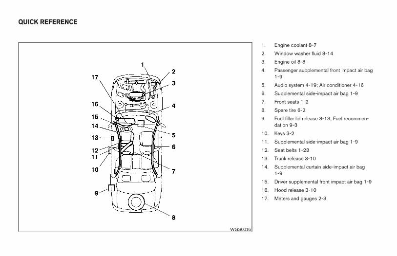
1. Engine coolant 8-7
2. Window washer fluid 8-14
3. Engine oil 8-8
4. Passenger supplemental front impact air bag1-9
5. Audio system 4-19; Air conditioner 4-16
6. Supplemental side-impact air bag 1-9
7. Front seats 1-2
8. Spare tire 6-2
9. Fuel filler lid release 3-13; Fuel recommen-dation 9-3
10. Keys 3-2
11. Supplemental side-impact air bag 1-9
12. Seat belts 1-23
13. Trunk release 3-10
14. Supplemental curtain side-impact air bag1-9
15. Driver supplemental front impact air bag 1-9
16. Hood release 3-10
17. Meters and gauges 2-3
WGS0016
QUICK REFERENCE
Z REVIEW COPY:—2004 Maxima (max)Owners Manual (owners)—USA English (nna)10/20/03—arosenma X