Embed Size (px)
Citation preview

Industrial Service Solutions
Electrical Arc Flash Hazards
Is your company in compliance?

2
May 2011
Discussion Highlights
� The Bigger Picture of Electrical Safety
� Arc Flash Risks and Effects
� Arc Flash Approach Boundaries
� Arc Flash Hazard CalculationsNFPA 70E TablesIEEE Standard 1584-2002
� Arc Flash Remediation
� Arc Flash Categories & Protective Clothing
� Arc Flash Labels and Permits

3
May 2011
Worker safety is important
Why?
• In addition to being the right thing to do it is intrinsically connected to productivity, worker morale and liability costs
• Machinery, processes & facilities usually designed with worker & machine safety as key consideration from start...
• However, electrical safety often handled differently… Late, after base system design is finished, sometimes after equipment is purchased . . .
It should not be !
• Electrical safety can best be optimized by being part of the initially defined mission for the facility’s power distribution system and being considered at every decision point in the design, purchasing and installation process.
4
May 2011
Safety, a bigger picture
See IEEE article by H. Landis Floyd II, “Potential Impact of ANSI Z10 AND CSA Z1000 on Reducing Electric Shock and Arc Flash Hazard Injuries”, PCIC 2009 conference record. Next few slides borrow heavily from this presentation
New standards for implementing safety programs in facilities
From ANSI Z10 Scope:
“… The purpose of the standard is to provide organizations an effective tool for continual improvement of their occupational health and safety performance. An OHSMS implemented in conformance with this standard can help organizations minimize workplace risks and reduce the occurrence and cost of occupational injuries, illnesses and fatalities. …”

5
May 2011
Hierarchy of Hazard Control Measures
1. Elimination of the hazard
2.Substitution for less hazardous equipment,
materials or process
3.Engineering control for less hazardous
exposure or severity
4. Warnings, signs, and other communications
5.Administrative controls including safe work
practices
6. Personal protective equipment
From ANSI Z10
For example:
A temporary setting such as a maintenance switch is an administrative procedure (5) …
Not as good as good as permanently making protection safer which would be a
substitution (2) or Engineering (3)
Thinking through this table allows assigning value to different potential solutions to arc flash & shock hazards

6
May 2011
Higher level solutions easier at system planning time
Elimination of the hazard
• The only true way for an electrical system to be safe is for it to be de-energized…
• But when a process is critical that is difficult to do unless system includes redundant ways to get power to loads…
Substitution of less hazardous equipment
1. Elimination of the hazard
2.Substitution for less hazardous equipment,
materials or process
3.Engineering control for less hazardous
exposure or severity
4. Warnings, signs, and other communications
5.Administrative controls including safe work
practices
6. Personal protective equipment
• Different types of equipment pose different levels of risk – individually mounted vs. group mounted, draw-out vs. stationary, arc resistant vs. standard, indoor vs. outdoor, etc.
3. Design controls, instrumentation, monitoring to minimize hazard
• Do everything than can be done remotely, remotely. Use modern diagnostics to minimize exposure and optimize reliability
7
May 2011
Hazards Involved in Working On or Near Energized Electrical Equipment
Dangers associated with working on or around exposed energized conductors or parts:
Electrical shock - Becoming part of the circuit.
Arc Flash - The violent release of superheated gases caused by an electric arc.
Arc Blast - The blast effects from the pressure wave associated with an arc flash occurrence.
Shrapnel - Ejection of projectiles or bits of metal.
Noise - From initial explosive expansion of air.

8
May 2011
NEC and OSHA References to NFPA 70E
• NEC Article 110.16 requires that Electrical equipment such as switchboards, panelboards, industrial control panels, meter socket enclosures, and motor control centers shall be field marked to warn qualified persons of potential electric arc flash hazards.
• NEC Article 100, Definitions: Qualified Persons has NFPA 70E referenced for electrical safety training requirements.
• OSHA regulation 29 CFR 1910 Subpart S (Electrical Safety) Appendix A: Reference Documents, also references NFPA 70E.
9
May 2011
OSHA Interpretations of NFPA 70EOSHA can, and has enforced lack of arc flash protection under the "general duty clause". Here are some excerpts from a standards interpretation letter written by OSHA in 2003:
“All your questions involve the NFPA 70E standard, which is one of many industry consensus standards developed by the National Fire Protection Association. NFPA 70E, which is titled ‘Electrical Safety Requirements for Employee Workplaces,’
is the NFPA’s consensus standard for workplace electrical safety. It covers employee protection from electrical hazards including shock, arc blasts, explosions initiated by electricity, outside conductors, etc.
“With respect to the General Duty Clause, industry consensus standards may be evidence that a hazard is ‘recognized’ and that there is a feasible means of correcting such a hazard.
“These provisions (1910.132(a) personal protective equipment) are written in general terms, requiring, for example, that personal protective equipment be provided ‘where necessary by reason of hazards…’ and requiring the employer to select equipment ‘that will protect the affected employee from the hazards…’.
“Industry consensus standards, such as NFPA 70E, can be used by employers as guides to making the assessments and equipment selections required by the standard. Similarly, in OSHA enforcement actions, they (70E) can be used as evidence of whether the employer acted reasonably.

10
May 2011
OSHA 1910 Subpart S RevisionsEffective Aug 13th, 2007
OSHA ADOPTING NFPA 70E
NFPA 70E-2000 is the basis for most of the final rule. However, there are
some parts based upon the 2002 NEC and even some selected parts of NFPA 70E 2004 Edition.
“(The final rule) reflects the Agency’s commitment to update its electrical standards, keep them consistent with NFPA standards, and ensure that they appropriately protect employees. The Agency intends to extend the
commitment by using NFPA 70E as a basis for future revisions to its electrical safety-related work practice requirements and new requirements for electrical maintenance and special equipment.”
---Preamble of the Final Rule document
11
May 2011
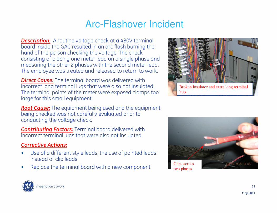
Description: A routine voltage check at a 480V terminal board inside the GAC resulted in an arc flash burning the hand of the person checking the voltage. The check consisting of placing one meter lead on a single phase and measuring the other 2 phases with the second meter lead. The employee was treated and released to return to work.
Direct Cause: The terminal board was delivered with incorrect long terminal lugs that were also not insulated. The terminal points of the meter were exposed clamps too large for this small equipment.
Root Cause: The equipment being used and the equipment being checked was not carefully evaluated prior to conducting the voltage check.
Contributing Factors: Terminal board delivered with incorrect terminal lugs that were also not insulated.
Corrective Actions:
• Use of a different style leads, the use of pointed leads instead of clip leads
• Replace the terminal board with a new component
Arc-Flashover Incident
Broken Insulator and extra long terminal
lugs
Clips across
two phases

12
May 2011
What May Happen with a Slow Protective Device

13
May 2011
Worker’s Flame-Resistant Shirt and Insulating Gloves
14
May 2011
Arc Flash Effects
• Temperature of the arc can reach 35,000 deg F – about 4 times the temperature of the sun!
• In US, 5-10 arc flash incidents requiring hospitalization per day.
• 1 – 2 deaths per day from electrical events, (shock, flash & blast).
• More than 2,000 workers treated in burn centers per year with severe arc flash injuries. (This does not include injuriesin other hospitals and clinics which go unreported.)

15
May 2011
Examples of Activities which Involve Arc Flash Risks
• Racking in or out of draw-out circuit breakers.
• Removing or installing circuit breakers or fuses.
• Working on control circuits with exposed energized primary parts.
• Applying safety grounds.
• Removing panel covers for inspections or other activities.
• Low voltage testing and diagnostics.
16
May 2011
Arc Flash Standards
Simplified Tabular method presented in:
• NFPA-70E-2009, “Standard for Electrical Safety Requirements for Employee Workplaces.”
• NFPA-70E-2012 to be released later in 2011
• In Canada Z462-08, “Workplace Electrical Safety”
More sophisticated calculated methods suitable for low voltage and higher voltages developed in:
• IEEE Std 1584-2002, “IEEE Guide for Performing Arc-Flash Hazard Calculations.”
• Amendment 1 issued in 2004 as IEEE Std 1584a-2004, (changes were relatively minor.)
• Sometimes combination of these two documents referred to as Std 1584-2004.
17
May 2011
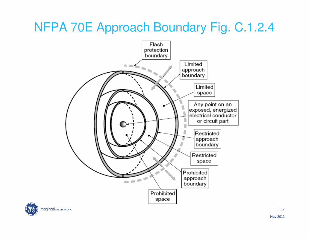
NFPA 70E Approach Boundary Fig. C.1.2.4

18
May 2011
Shock Protection Approach Boundaries
Fixed Live
Part
Prohibited
Approach Distance
Restricted
Approach Distance
Limited
Approach Distance
@15,000 Volts 5 ft, 0 in2 ft, 2 in0', 7"
@480 Volts 0', 1" 1 ft, 0 in 3 ft, 6 in
Limited Approach Boundary – Distance from an exposed live part within which a shock hazard exists.
Restricted Approach Boundary – Distance from an exposed live part within which there is an increased risk of shock, due to electrical arc over combined with inadvertent movement, for personnel working in close proximity to the live part.
Prohibited Approach Boundary – Distance from an exposed live part within which work is considered the same as making contact with the live part.
19
May 2011
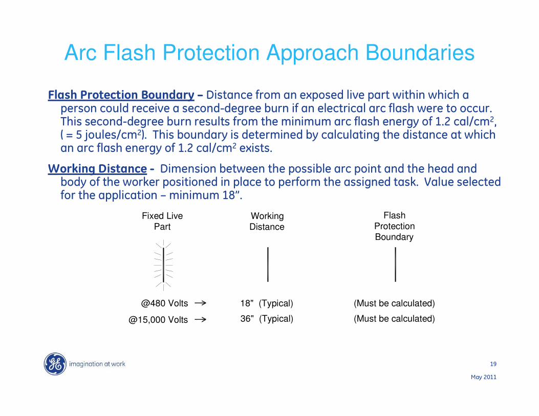
Arc Flash Protection Approach Boundaries
Flash Protection Boundary – Distance from an exposed live part within which a person could receive a second-degree burn if an electrical arc flash were to occur. This second-degree burn results from the minimum arc flash energy of 1.2 cal/cm2, ( = 5 joules/cm2). This boundary is determined by calculating the distance at which an arc flash energy of 1.2 cal/cm2 exists.
Working Distance - Dimension between the possible arc point and the head and body of the worker positioned in place to perform the assigned task. Value selected for the application – minimum 18”.
Flash Protection Boundary
WorkingDistance
Fixed Live Part
@15,000 Volts
@480 Volts 18" (Typical)
36" (Typical) (Must be calculated)
(Must be calculated)
20
May 2011
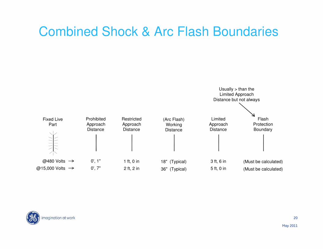
Combined Shock & Arc Flash Boundaries
Fixed Live Part
@480 Volts
@15,000 Volts
Limited
Approach Distance
Restricted
Approach Distance
Prohibited
Approach Distance
0', 1"
0', 7"
1 ft, 0 in
2 ft, 2 in
3 ft, 6 in
5 ft, 0 in
(Arc Flash)
WorkingDistance
18" (Typical)
36" (Typical)
Flash
Protection Boundary
(Must be calculated)
(Must be calculated)
Usually > than the
Limited Approach
Distance but not always

21
May 2011
Safe Approach Distances
Unqualified persons – Safe when maintaining a distance from exposed energized parts equal to the Limited Approach Boundary or the Flash Protection Boundary, whichever is greater.
Qualified persons
Appropriate arc flash protection shall be utilized if flash protection boundary crossed.
>>> To cross the Restricted Approach Boundary, the qualified person must:
•Have a documented work plan approved by management.
•Use appropriate protective equipment for work near exposed conductors and rated for voltage and energy level.
•Be certain no part of body enters prohibited space.
•Keep as much as body as possible out of restricted space.

22
May 2011
Safe Approach Distances
Qualified persons
Appropriate arc flash protection shall be utilized if flash protection boundary crossed.
>>> To cross the Prohibited Approach Boundary, which is considered the same as making contact with exposed energized conductors or parts, the qualified person must:
•Have specific training for working on energized parts
•Have a documented plan justifying the need to work that close approved by management.
•Perform a risk analysis approved by management.
•Use appropriate protective equipment for work on exposed conductors and rated for voltage and energy level.
23
May 2011
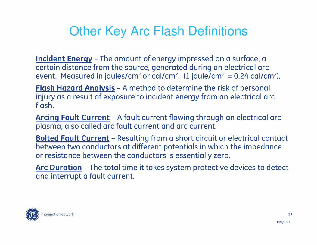
Other Key Arc Flash Definitions
Incident Energy – The amount of energy impressed on a surface, a certain distance from the source, generated during an electrical arc event. Measured in joules/cm2 or cal/cm2. (1 joule/cm2 = 0.24 cal/cm2).
Flash Hazard Analysis – A method to determine the risk of personal injury as a result of exposure to incident energy from an electrical arc flash.
Arcing Fault Current – A fault current flowing through an electrical arc plasma, also called arc fault current and arc current.
Bolted Fault Current – Resulting from a short circuit or electrical contact between two conductors at different potentials in which the impedance or resistance between the conductors is essentially zero.
Arc Duration – The total time it takes system protective devices to detect and interrupt a fault current.
24
May 2011
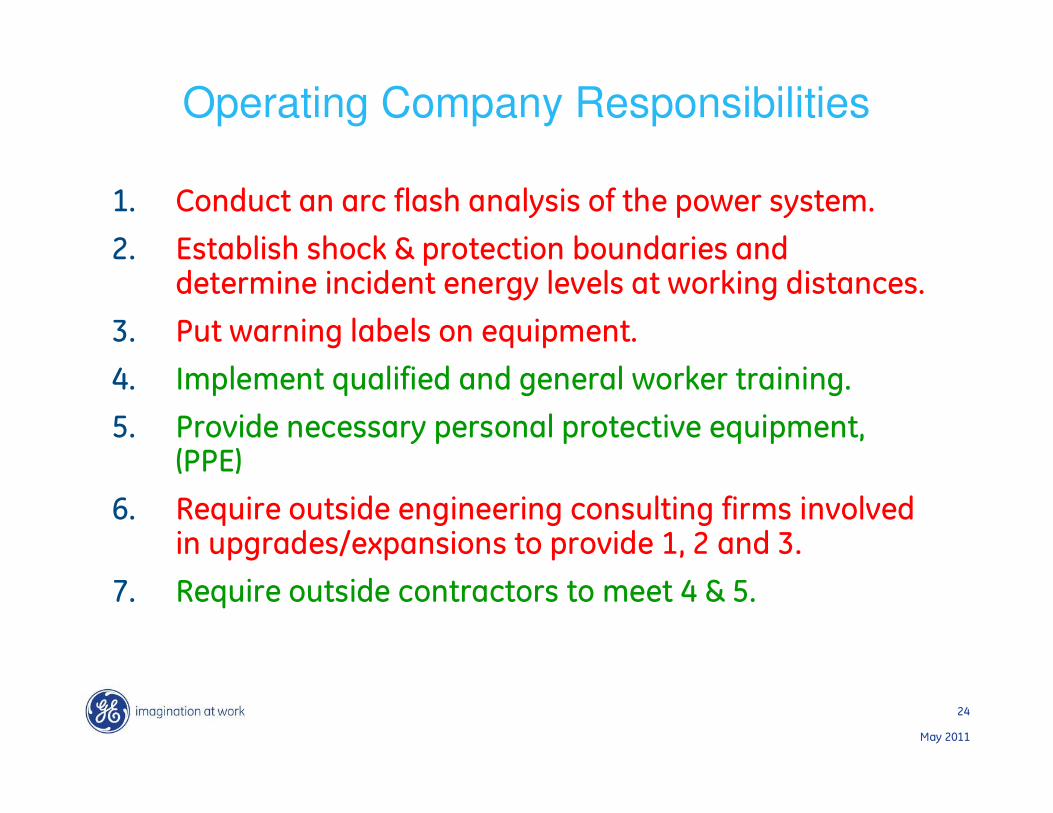
Operating Company Responsibilities
1. Conduct an arc flash analysis of the power system.
2. Establish shock & protection boundaries and determine incident energy levels at working distances.
3. Put warning labels on equipment.
4. Implement qualified and general worker training.
5. Provide necessary personal protective equipment, (PPE)
6. Require outside engineering consulting firms involved in upgrades/expansions to provide 1, 2 and 3.
7. Require outside contractors to meet 4 & 5.

25
May 2011
Steps in Performing an Arc Flash Hazard Analysis
1. Collect power system data.
2. Determine the system modes of operation.
3. Determine the bolted fault currents.
4. Determine the arcing fault currents.
5. Find protective device characteristics and arc durations.
6. Document system voltage levels and equipment classes.
7. Select the working distances.
8. Determine the incident energies for all equipment
9. Determine the flash protection boundary for all equipment.

26
May 2011
Performing an Arc Flash Hazard Analysis
• Methods
o NFPA 70E Table 130.7 (C)(9)
o Spreadsheets
o Power System Analysis Software
• Arc Flash calculation modules can be obtained with commercially available comprehensive power system modeling software.
• Short-Circuit Study
• Protective Device Coordination Analysis
• Arc Flash analysis (Per NFPA 70E or IEEE 1584)

27
May 2011
Potential product based solutionsKeep people away from the equipment as much as possible
• Remote diagnostics, metering and controls
• Advanced diagnostics to implement condition based maintenance
Protect as fast as possible & as sensitive as possible without giving up selectivity
• Use zone selective interlocking and/or bus differential
• Use faster electronics and/or faster circuit breakers, or small fuses
• Use better instantaneous algorithms that allow low pick up settings
• Use light sensing for controlling CBs as an alternative sensitive instantaneous
Use arc resistant enclosures and/or equipment
• Passive Arc Resistant equipment – Only if doors and panels closed & does not protect equipment
• Active Arc Resistant equipment - crowbars or similar driven by light sensing
Use temporary sensitive instantaneous protection (maintenance setting)
Use local “off” switching
28
May 2011
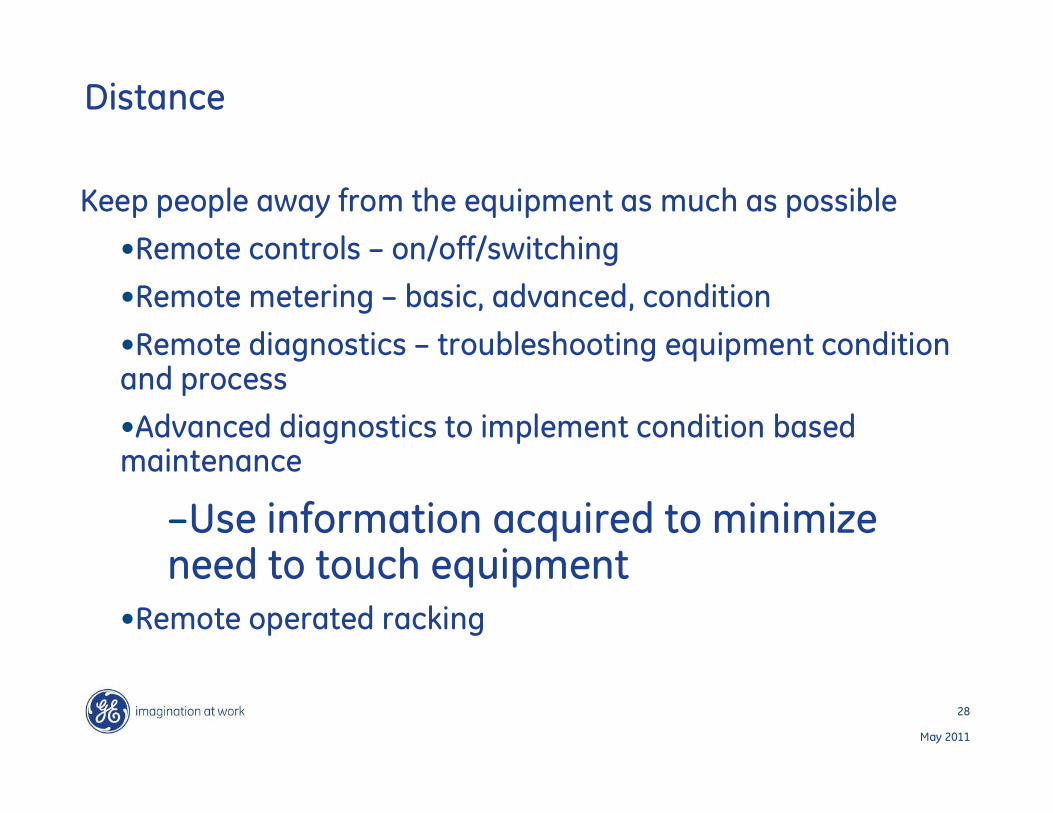
Distance
Keep people away from the equipment as much as possible
•Remote controls – on/off/switching
•Remote metering – basic, advanced, condition
•Remote diagnostics – troubleshooting equipment condition and process
•Advanced diagnostics to implement condition based maintenance
–Use information acquired to minimize need to touch equipment
•Remote operated racking
29
May 2011
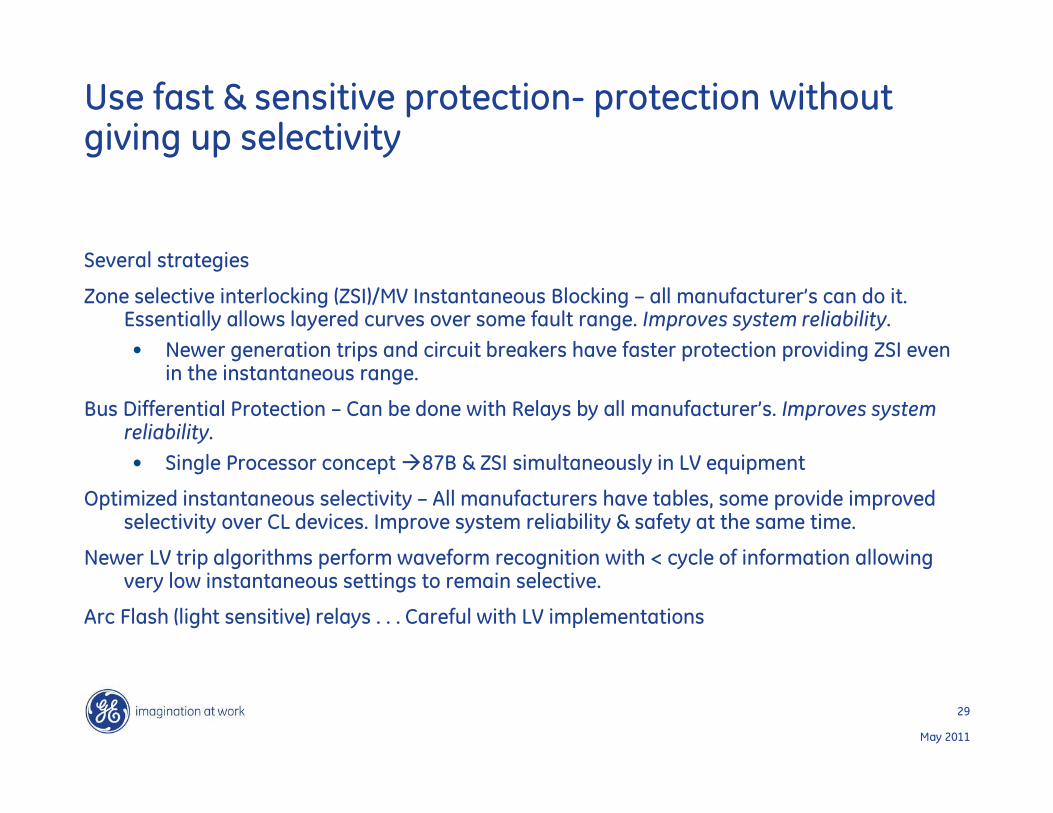
Use fast & sensitive protection- protection without giving up selectivity
Several strategies
Zone selective interlocking (ZSI)/MV Instantaneous Blocking – all manufacturer’s can do it. Essentially allows layered curves over some fault range. Improves system reliability.
• Newer generation trips and circuit breakers have faster protection providing ZSI even in the instantaneous range.
Bus Differential Protection – Can be done with Relays by all manufacturer’s. Improves system reliability.
• Single Processor concept �87B & ZSI simultaneously in LV equipment
Optimized instantaneous selectivity – All manufacturers have tables, some provide improved selectivity over CL devices. Improve system reliability & safety at the same time.
Newer LV trip algorithms perform waveform recognition with < cycle of information allowing very low instantaneous settings to remain selective.
Arc Flash (light sensitive) relays . . . Careful with LV implementations
30
May 2011
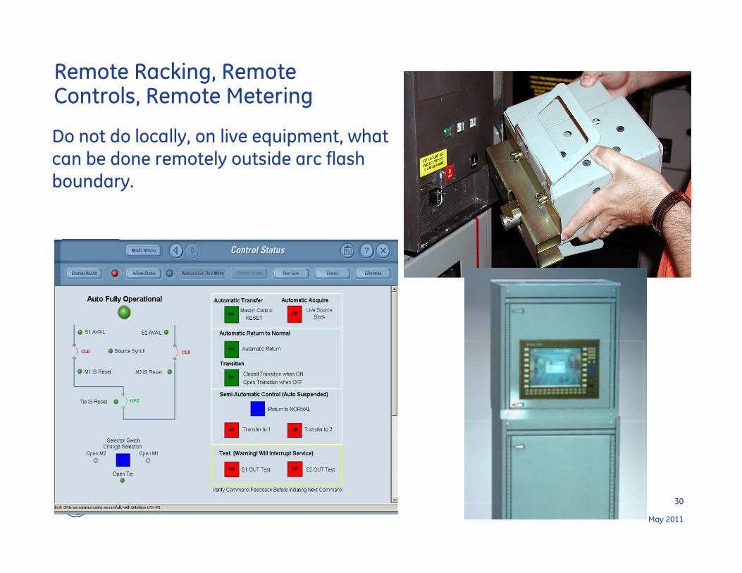
Remote Racking, Remote Controls, Remote Metering
Do not do locally, on live equipment, what
can be done remotely outside arc flash
boundary.
31
May 2011
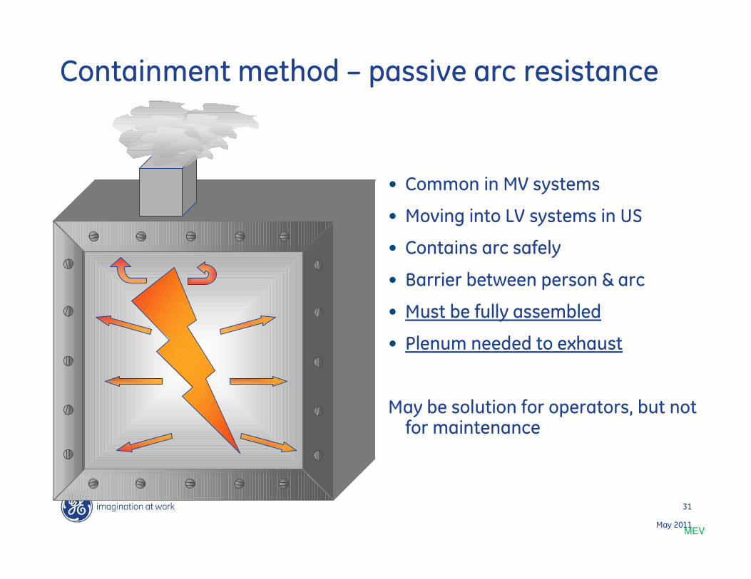
Containment method – passive arc resistance
• Common in MV systems
• Moving into LV systems in US
• Contains arc safely
• Barrier between person & arc
• Must be fully assembled
• Plenum needed to exhaust
May be solution for operators, but not for maintenance
MEV
32
May 2011
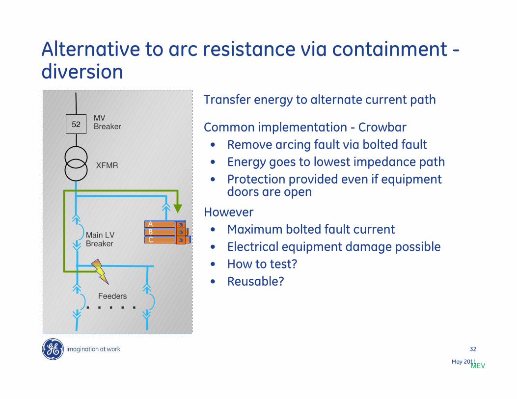
Alternative to arc resistance via containment -diversion
Transfer energy to alternate current path
Common implementation - Crowbar
• Remove arcing fault via bolted fault
• Energy goes to lowest impedance path
• Protection provided even if equipment doors are open
However
• Maximum bolted fault current
• Electrical equipment damage possible
• How to test?
• Reusable?
MEV
Main LVBreaker
Feeders. . . . .
XFMR
52MVBreaker
BC
A

33
May 2011
34
May 2011
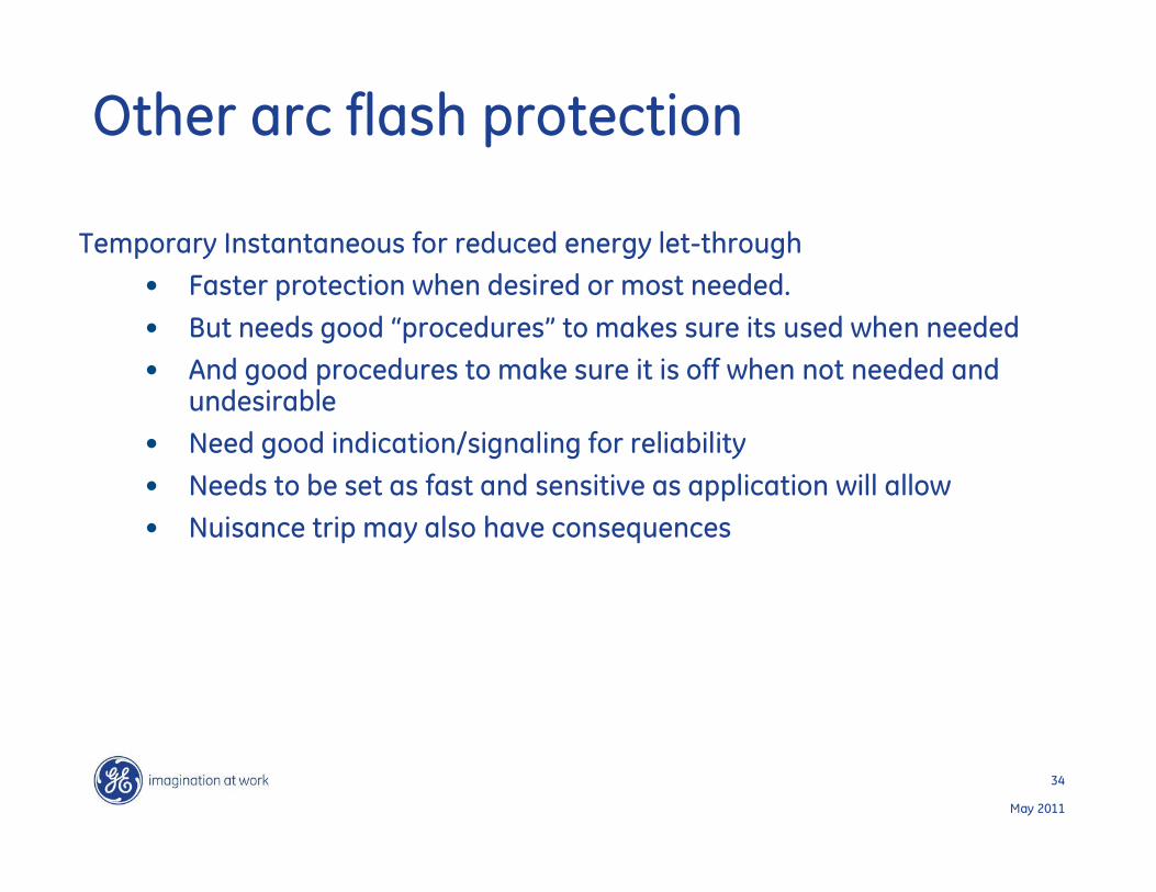
Other arc flash protection
Temporary Instantaneous for reduced energy let-through
• Faster protection when desired or most needed.
• But needs good “procedures” to makes sure its used when needed
• And good procedures to make sure it is off when not needed and undesirable
• Need good indication/signaling for reliability
• Needs to be set as fast and sensitive as application will allow
• Nuisance trip may also have consequences
35
May 2011
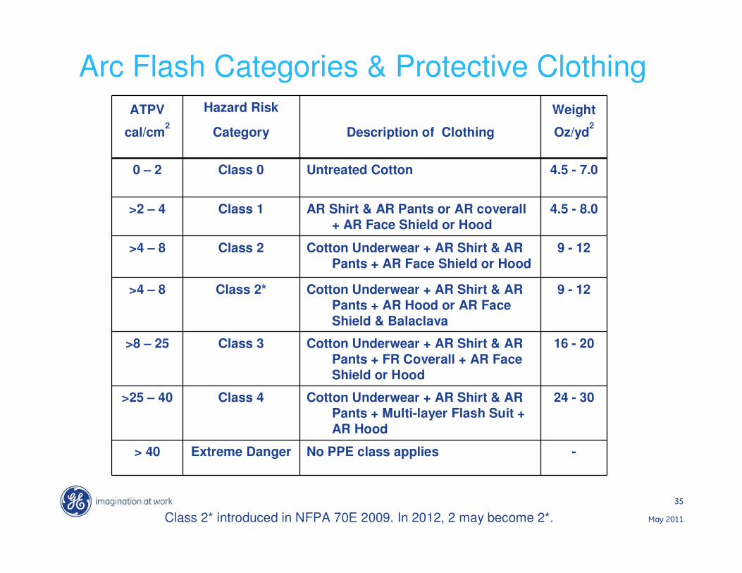
Arc Flash Categories & Protective Clothing
ATPV Hazard Risk Weight
cal/cm2
Category Description of Clothing Oz/yd2
0 – 2 Class 0 Untreated Cotton 4.5 - 7.0
>2 – 4 Class 1 AR Shirt & AR Pants or AR coverall
+ AR Face Shield or Hood
4.5 - 8.0
>4 – 8 Class 2 Cotton Underwear + AR Shirt & AR
Pants + AR Face Shield or Hood
9 - 12
>4 – 8 Class 2* Cotton Underwear + AR Shirt & AR
Pants + AR Hood or AR Face
Shield & Balaclava
9 - 12
>8 – 25 Class 3 Cotton Underwear + AR Shirt & AR
Pants + FR Coverall + AR Face
Shield or Hood
16 - 20
>25 – 40 Class 4 Cotton Underwear + AR Shirt & AR
Pants + Multi-layer Flash Suit +
AR Hood
24 - 30
> 40 Extreme Danger No PPE class applies -
Class 2* introduced in NFPA 70E 2009. In 2012, 2 may become 2*.

36
May 2011
Arc Flash PPE
HRC 2 HRC 3&4HRC 2*HRC 1
37
May 2011
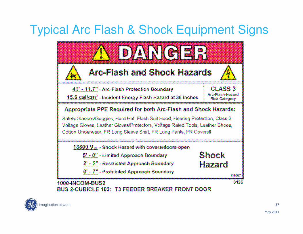
Typical Arc Flash & Shock Equipment Signs

38
May 2011
Typical Shock & Arc Flash Work Permit

39
May 2011
Thank you!
Any questions?