Embed Size (px)
DESCRIPTION
(FR) Le PCI Express se démocratise de plus en plus dans les serveurs. Présents depuis des années comme bus pour les cartes d'extensions, on va maintenant le trouver en façades des serveurs pour servir des disque flash 2,5 pouces (connecteur SF-8639) et sous la forme de câble appelés OCulink. (EN) PCI Express is becoming more and more present in servers. As a communication bus for extension cards since years, now it will serve 2.5 inches flash drive and through PCIe cables named OCulink. Auteurs/Authors: Michael Hall Director of Technology Solutions Enabling, Data Center Group, Intel Corporation Jonmichael Hands Technical Program Manager, Non-Volatile Memory Solutions Group, Intel Corporation
Citation preview
PCI Express* based Storage: Data Center NVM Express* Platform Topologies
Michael HallDirector of Technology Solutions Enabling, Data Center Group, Intel Corporation
Jonmichael HandsTechnical Program Manager, Non-Volatile Memory Solutions Group, Intel Corporation
SSDS004
2
Agenda
• PCI Express* SSD Data Center Ecosystem – what is the opportunity?
• Platform topology options
• Validation tools and methodologies
• Hot plug support for Intel® Xeon® processor based servers
• Upcoming workshops
3
Agenda
• PCI Express* SSD Data Center Ecosystem – what is the opportunity?
• Platform topology options
• Validation tools and methodologies
• Hot plug support for Intel® Xeon® processor based servers
• Upcoming workshops
4
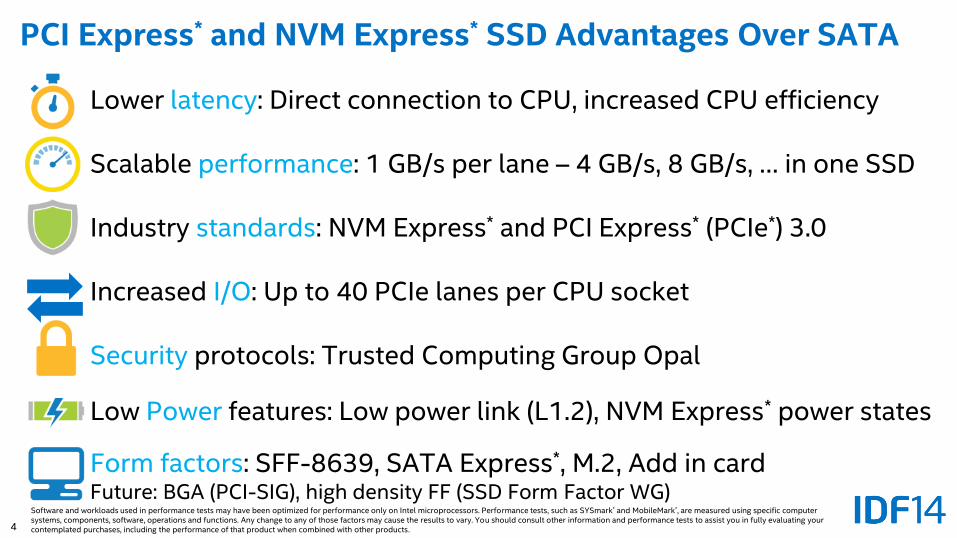
PCI Express* and NVM Express* SSD Advantages Over SATA
Lower latency: Direct connection to CPU, increased CPU efficiency
Scalable performance: 1 GB/s per lane – 4 GB/s, 8 GB/s, … in one SSD
Industry standards: NVM Express* and PCI Express* (PCIe*) 3.0
Increased I/O: Up to 40 PCIe lanes per CPU socket
Security protocols: Trusted Computing Group Opal
Low Power features: Low power link (L1.2), NVM Express* power states
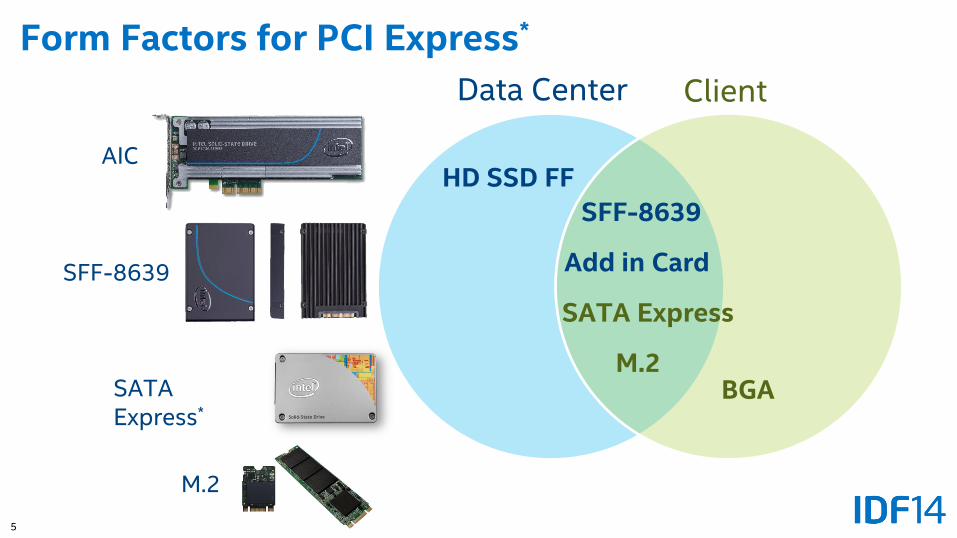
Form factors: SFF-8639, SATA Express*, M.2, Add in card Future: BGA (PCI-SIG), high density FF (SSD Form Factor WG)
Software and workloads used in performance tests may have been optimized for performance only on Intel microprocessors. Performance tests, such as SYSmark* and MobileMark*, are measured using specific computer systems, components, software, operations and functions. Any change to any of those factors may cause the results to vary. You should consult other information and performance tests to assist you in fully evaluating your contemplated purchases, including the performance of that product when combined with other products.
5
Form Factors for PCI Express*
Data Center Client
SFF-8639
SATA Express
AIC
SFF-8639
SATA Express*
M.2
Add in Card
M.2BGA
HD SSD FF
6
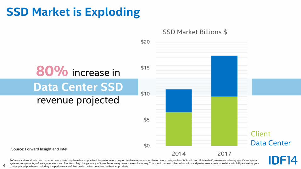
80% increase in
Data Center SSDrevenue projected
SSD Market is Exploding
Source: Forward Insight and Intel$0
$5
$10
$15
$20
2014 2017
SSD Market Billions $
ClientData Center
Software and workloads used in performance tests may have been optimized for performance only on Intel microprocessors. Performance tests, such as SYSmark* and MobileMark*, are measured using specific computer systems, components, software, operations and functions. Any change to any of those factors may cause the results to vary. You should consult other information and performance tests to assist you in fully evaluating your contemplated purchases, including the performance of that product when combined with other products.
7
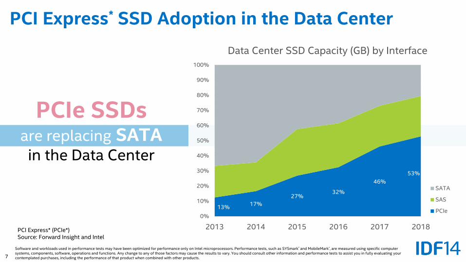
PCIe SSDsare replacing SATAin the Data Center
PCI Express* SSD Adoption in the Data Center
13%17%
27%32%
46%
53%
0%
10%
20%
30%
40%
50%
60%
70%
80%
90%
100%
2013 2014 2015 2016 2017 2018
Data Center SSD Capacity (GB) by Interface
SATA
SAS
PCIe
PCI Express* (PCIe*)Source: Forward Insight and Intel
Software and workloads used in performance tests may have been optimized for performance only on Intel microprocessors. Performance tests, such as SYSmark* and MobileMark*, are measured using specific computer systems, components, software, operations and functions. Any change to any of those factors may cause the results to vary. You should consult other information and performance tests to assist you in fully evaluating your contemplated purchases, including the performance of that product when combined with other products.
8
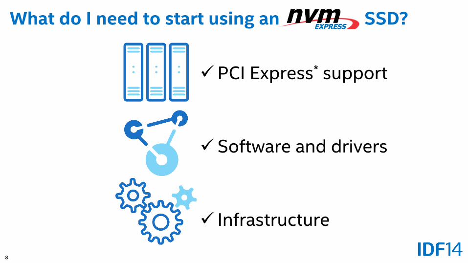
What do I need to start using an SSD?
PCI Express* support
Software and drivers
Infrastructure
9
Agenda
• PCI Express* SSD Data Center Ecosystem – what is the opportunity?
• Platform topology options
• Validation tools and methodologies
• Hot plug support for Intel® Xeon® processor based servers
• Upcoming workshops
10
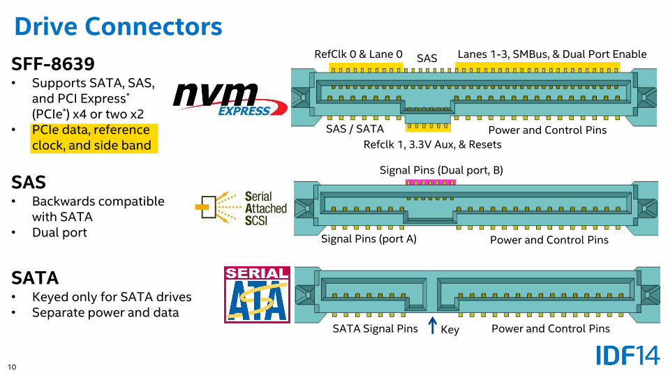
Drive Connectors
SATA Signal Pins Power and Control Pins
SATA• Keyed only for SATA drives• Separate power and data
Key
Signal Pins (port A) Power and Control Pins
Signal Pins (Dual port, B)
SAS• Backwards compatible
with SATA• Dual port
SFF-8639• Supports SATA, SAS,
and PCI Express*
(PCIe*) x4 or two x2• PCIe data, reference
clock, and side band
SAS / SATA Power and Control Pins
SASRefClk 0 & Lane 0 Lanes 1-3, SMBus, & Dual Port Enable
Refclk 1, 3.3V Aux, & Resets
11
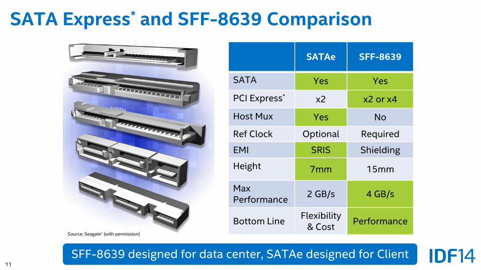
SATA Express* and SFF-8639 Comparison
SATAe SFF-8639
SATA Yes Yes
PCI Express* x2 x2 or x4
Host Mux Yes No
Ref Clock Optional Required
EMI SRIS Shielding
Height 7mm 15mm
MaxPerformance
2 GB/s 4 GB/s
Bottom LineFlexibility
& CostPerformance
SFF-8639 designed for data center, SATAe designed for Client
Source: Seagate* (with permission)
12
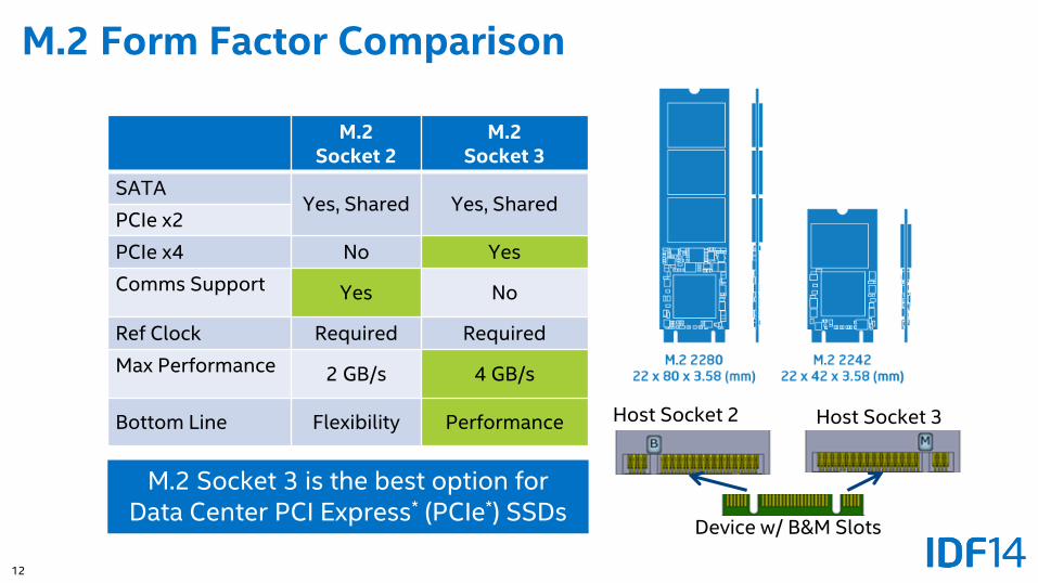
M.2 Form Factor Comparison
Host Socket 2 Host Socket 3
Device w/ B&M Slots
M.2 Socket 2
M.2 Socket 3
SATAYes, Shared Yes, Shared
PCIe x2
PCIe x4 No Yes
Comms Support Yes No
Ref Clock Required Required
Max Performance 2 GB/s 4 GB/s
Bottom Line Flexibility Performance
M.2 Socket 3 is the best option for Data Center PCI Express* (PCIe*) SSDs
13
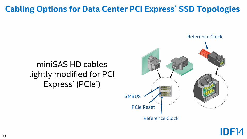
Cabling Options for Data Center PCI Express* SSD Topologies
Reference Clock
PCIe Reset
SMBUS
miniSAS HD cables lightly modified for PCI
Express* (PCIe*)
Reference Clock
14
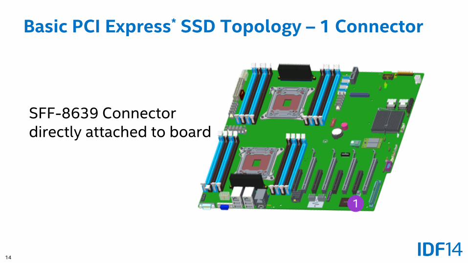
Basic PCI Express* SSD Topology – 1 Connector
SFF-8639 Connector directly attached to board
1
15
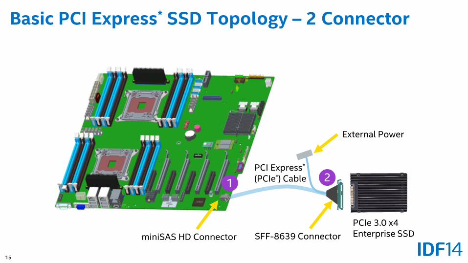
Basic PCI Express* SSD Topology – 2 Connector
1 2
miniSAS HD Connector
PCI Express*
(PCIe*) Cable
PCIe 3.0 x4 Enterprise SSDSFF-8639 Connector
External Power
16
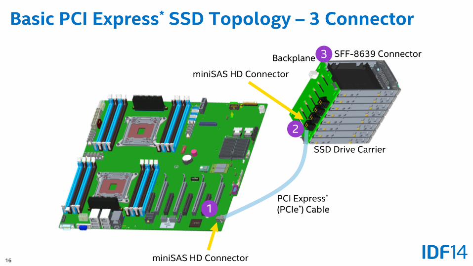
Basic PCI Express* SSD Topology – 3 Connector
Motherboard
1
miniSAS HD Connector
PCI Express*
(PCIe*) Cable
miniSAS HD Connector
3Backplane
SSD Drive Carrier
SFF-8639 Connector
2
17
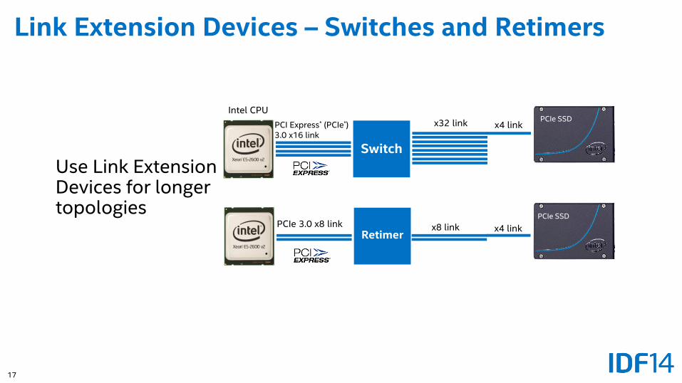
Link Extension Devices – Switches and Retimers
Use Link Extension Devices for longer topologies
RetimerPCIe 3.0 x8 link x8 link
PCIe SSD
x4 link
Switch
PCI Express* (PCIe*) 3.0 x16 link
x32 linkPCIe SSD
x4 link
Intel CPU
18
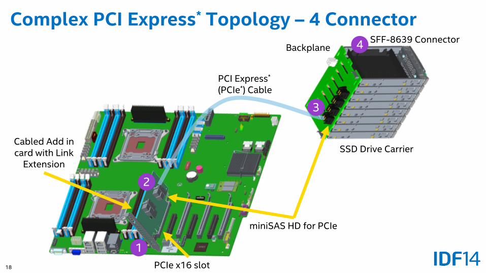
Complex PCI Express* Topology – 4 Connector
PCIe x16 slot
PCI Express*
(PCIe*) Cable
Cabled Add in card with Link
Extension
miniSAS HD for PCIe
Backplane
SSD Drive Carrier
1
2
3
4 SFF-8639 Connector
19
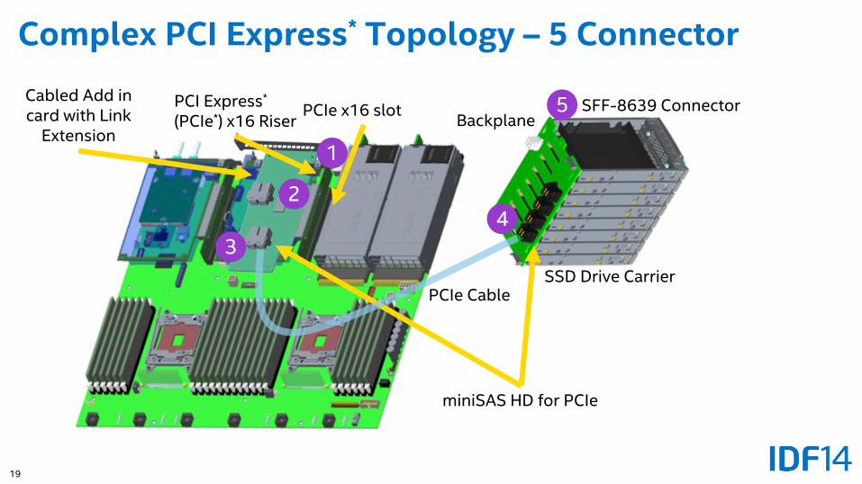
Complex PCI Express* Topology – 5 Connector
PCIe x16 slot
PCIe Cable
Cabled Add in card with Link
Extension
miniSAS HD for PCIe
Backplane
SSD Drive Carrier
1
24
SFF-8639 ConnectorPCI Express*
(PCIe*) x16 Riser
3
5
20
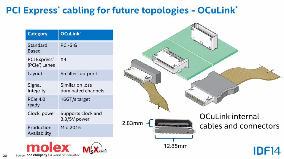
PCI Express* cabling for future topologies - OCuLink*
Category OCuLink*
Standard Based
PCI-SIG
PCI Express*
(PCIe*) LanesX4
Layout Smaller footprint
Signal Integrity
Similar on loss dominated channels
PCIe 4.0ready
16GT/s target
Clock, power Supports clock and 3.3/5V power
Production Availability
Mid 2015
12.85mm
2.83mm
Source:
OCuLink internal cables and connectors
21
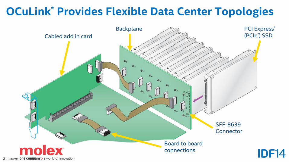
OCuLink* Provides Flexible Data Center Topologies
Board to board connections
Cabled add in card
Backplane
SFF-8639 Connector
PCI Express*
(PCIe*) SSD
Source:
22
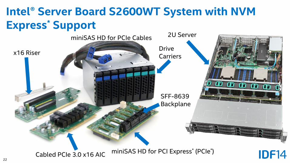
Intel® Server Board S2600WT System with NVM Express* Support
Cabled PCIe 3.0 x16 AIC
SFF-8639Backplane
miniSAS HD for PCI Express* (PCIe*)
x16 Riser
miniSAS HD for PCIe Cables
DriveCarriers
2U Server
23
Agenda
• PCI Express* SSD Data Center Ecosystem – what is the opportunity?
• Platform topology options
• Validation tools and methodologies
• Hot plug support for Intel® Xeon® processor based servers
• Upcoming workshops
24
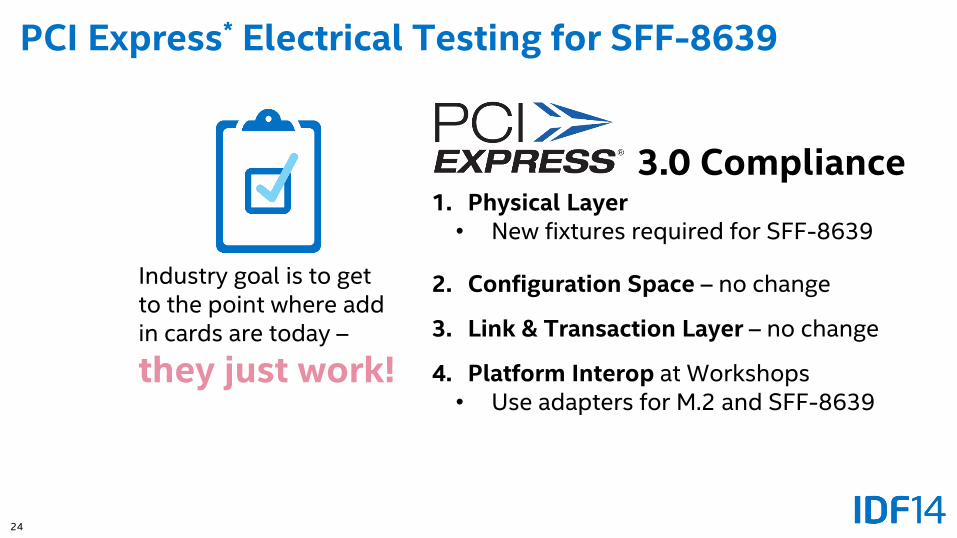
Industry goal is to get to the point where add in cards are today –
they just work!
1. Physical Layer• New fixtures required for SFF-8639
2. Configuration Space – no change
3. Link & Transaction Layer – no change
4. Platform Interop at Workshops• Use adapters for M.2 and SFF-8639
PCI Express* Electrical Testing for SFF-8639
3.0 Compliance
25
Agenda
• PCI Express* SSD Data Center Ecosystem – what is the opportunity?
• Platform topology options
• Validation tools and methodologies
• Hot plug support for Intel® Xeon® processor based servers
• Upcoming workshops
26
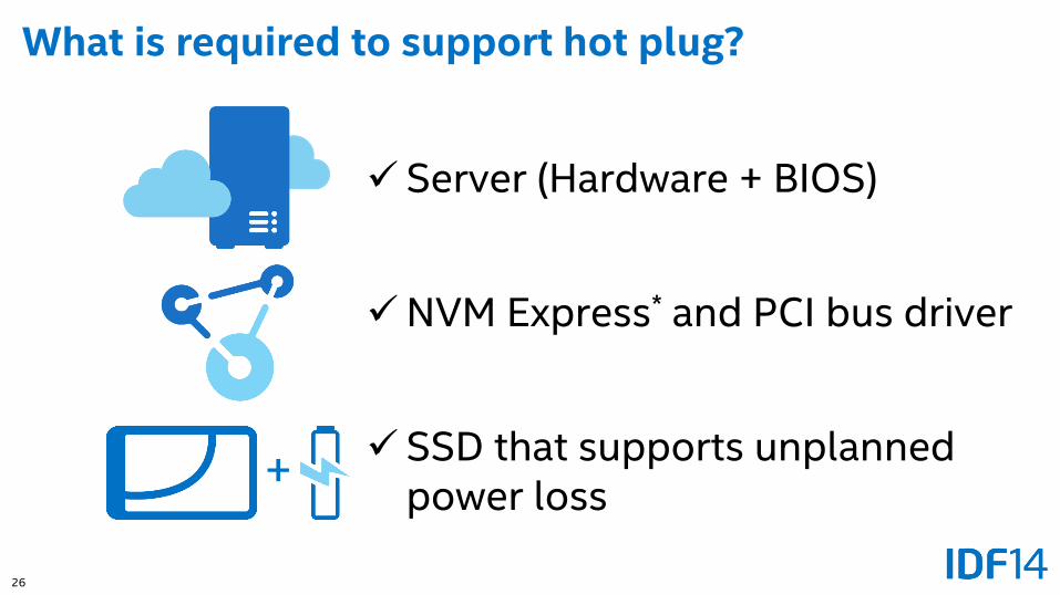
What is required to support hot plug?
+
Server (Hardware + BIOS)
NVM Express* and PCI bus driver
SSD that supports unplanned power loss
27
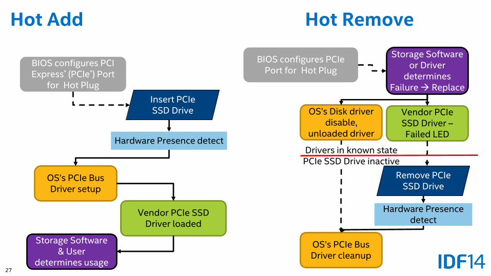
Hot Add Hot Remove
Insert PCIeSSD Drive
BIOS configures PCI Express* (PCIe*) Port
for Hot Plug
OS’s PCIe Bus Driver setup
Hardware Presence detect
Vendor PCIe SSD Driver loaded
Storage Software & User
determines usage
Drivers in known statePCIe SSD Drive inactive
Remove PCIeSSD Drive
BIOS configures PCIePort for Hot Plug
OS’s Disk driver disable,
unloaded driver
Hardware Presence detect
Vendor PCIeSSD Driver –Failed LED
Storage Software or Driver
determines Failure Replace
OS’s PCIe Bus Driver cleanup
28
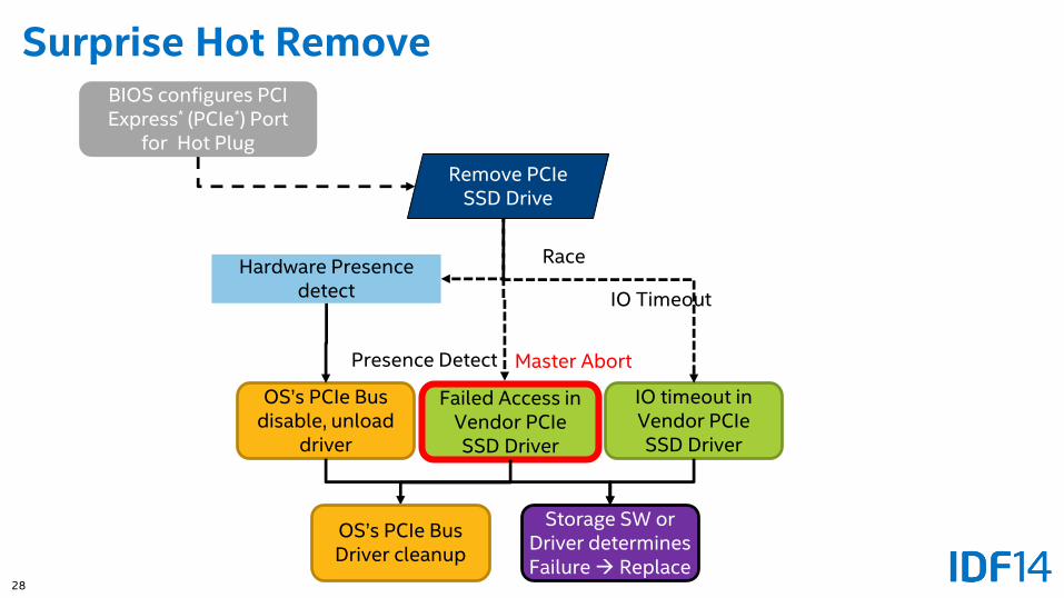
Presence Detect
IO Timeout
Drive Active
Surprise Hot RemoveBIOS configures PCI Express* (PCIe*) Port
for Hot Plug
Hardware Presence detect
Failed Access in Vendor PCIeSSD Driver
Storage SW or Driver determines Failure Replace
OS’s PCIe Bus disable, unload
driver
IO timeout in Vendor PCIeSSD Driver
Race
Master Abort
OS’s PCIe Bus Driver cleanup
Remove PCIeSSD Drive
29
Agenda
• PCI Express* SSD Data Center Ecosystem – what is the opportunity?
• Platform topology options
• Validation tools and methodologies
• Hot plug support for Intel® Xeon® processor based servers
• Upcoming workshops
30
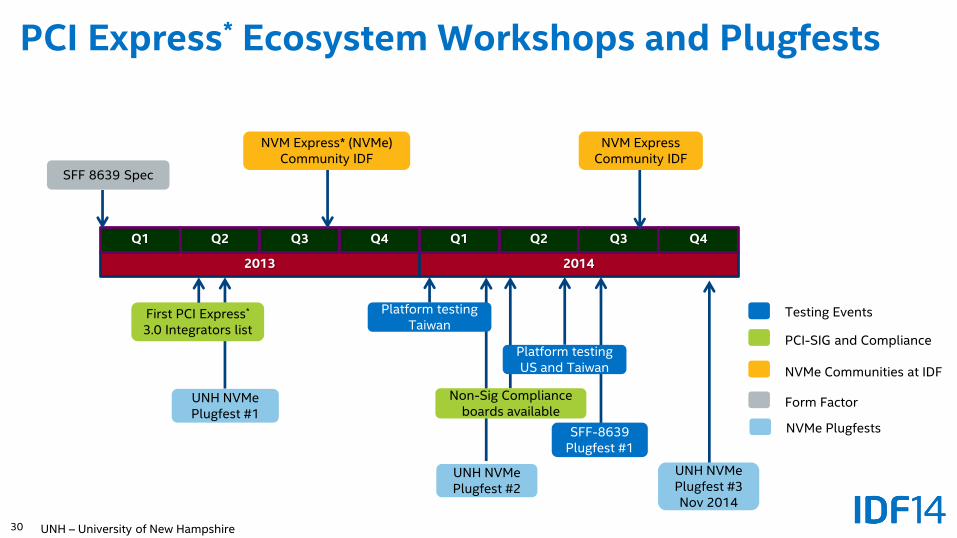
2013 2014
Q1 Q2 Q3 Q4Q1 Q2 Q3 Q4
NVM Express* (NVMe) Community IDF
NVM Express Community IDF
SFF 8639 Spec
Platform testing Taiwan
Platform testingUS and Taiwan
Non-Sig Compliance boards available
SFF-8639Plugfest #1
UNH NVMePlugfest #1
UNH NVMePlugfest #2
UNH NVMePlugfest #3Nov 2014
First PCI Express*
3.0 Integrators list
Testing Events
PCI-SIG and Compliance
NVMe Communities at IDF
Form Factor
PCI Express* Ecosystem Workshops and Plugfests
NVMe Plugfests
UNH – University of New Hampshire
31
• NVM Express* (NVMe) Solid-State Drives are going to become pervasive in the data center
• Intel is accelerating the ecosystem to make it easier to deploy complex PCI Express* (PCIe*) SSD topologies with Intel® Xeon® processor based platforms
• PCIe provides multiple form factors and flexible topologies for designing into servers and market segments with different requirements
• Start designing new PCI Express form factors into servers to take full advantage of NVMe!
Summary
32
• Design servers to support PCI Express* (PCIe*) Solid-State Drives to take advantage of the performance and efficiency of NVM Express* (NVMe) SSDs
• Get involved with NVMe at www.nvmexpress.org and participate with PCI-SIG at www.pcisig.com for developments of new storage technology
• See your Intel representative for more information about what Intel is doing to accelerate PCIe SSDs in the data center
• Participate in industry events to advance the PCIe ecosystem to support new form factors and topologies
Next Steps
33
A PDF of this presentation is available from our Technical Session Catalog: www.intel.com/idfsessionsSF. This URL is also printed on the top of Session Agenda Pages in the Pocket Guide.
Demos in the showcase – Booths #175 and #259
Additional info in the NVM Express* community – Booths #161-178
More web based info: www.intel.com\ssd
Additional Sources of Information
34
Legal DisclaimerINFORMATION IN THIS DOCUMENT IS PROVIDED IN CONNECTION WITH INTEL PRODUCTS. NO LICENSE, EXPRESS OR IMPLIED, BY ESTOPPEL OR OTHERWISE, TO ANY INTELLECTUAL PROPERTY RIGHTS IS GRANTED BY THIS DOCUMENT. EXCEPT AS PROVIDED IN INTEL'S TERMS AND CONDITIONS OF SALE FOR SUCH PRODUCTS, INTEL ASSUMES NO LIABILITY WHATSOEVER AND INTEL DISCLAIMS ANY EXPRESS OR IMPLIED WARRANTY, RELATING TO SALE AND/OR USE OF INTEL PRODUCTS INCLUDING LIABILITY OR WARRANTIES RELATING TO FITNESS FOR A PARTICULAR PURPOSE, MERCHANTABILITY, OR INFRINGEMENT OF ANY PATENT, COPYRIGHT OR OTHER INTELLECTUAL PROPERTY RIGHT.A "Mission Critical Application" is any application in which failure of the Intel Product could result, directly or indirectly, in personal injury or death. SHOULD YOU PURCHASE OR USE INTEL'S PRODUCTS FOR ANY SUCH MISSION CRITICAL APPLICATION, YOU SHALL INDEMNIFY AND HOLD INTEL AND ITS SUBSIDIARIES, SUBCONTRACTORS AND AFFILIATES, AND THE DIRECTORS, OFFICERS, AND EMPLOYEES OF EACH, HARMLESS AGAINST ALL CLAIMS COSTS, DAMAGES, AND EXPENSES AND REASONABLE ATTORNEYS' FEES ARISING OUT OF, DIRECTLY OR INDIRECTLY, ANY CLAIM OF PRODUCT LIABILITY, PERSONAL INJURY, OR DEATH ARISING IN ANY WAY OUT OF SUCH MISSION CRITICAL APPLICATION, WHETHER OR NOT INTEL OR ITS SUBCONTRACTOR WAS NEGLIGENT IN THE DESIGN, MANUFACTURE, OR WARNING OF THE INTEL PRODUCT OR ANY OF ITS PARTS.Intel may make changes to specifications and product descriptions at any time, without notice. Designers must not rely on the absence or characteristics of any features or instructions marked "reserved" or "undefined". Intel reserves these for future definition and shall have no responsibility whatsoever for conflicts or incompatibilities arising from future changes to them. The information here is subject to change without notice. Do not finalize a design with this information.Software and workloads used in performance tests may have been optimized for performance only on Intel microprocessors. Performance tests, such as SYSmark* and MobileMark*, are measured using specific computer systems, components, software, operations and functions. Any change to any of those factors may cause the results to vary. You should consult other information and performance tests to assist you in fully evaluating your contemplated purchases, including the performance of that product when combined with other products. The products described in this document may contain design defects or errors known as errata which may cause the product to deviate from published specifications. Current characterized errata are available on request.Contact your local Intel sales office or your distributor to obtain the latest specifications and before placing your product order.Copies of documents which have an order number and are referenced in this document, or other Intel literature, may be obtained by calling 1-800-548-4725, or go to: http://www.intel.com/design/literature.htm
Intel, Xeon, Look Inside and the Intel logo are trademarks of Intel Corporation in the United States and other countries.
*Other names and brands may be claimed as the property of others.Copyright ©2014 Intel Corporation.
35
Risk FactorsThe above statements and any others in this document that refer to plans and expectations for the second quarter, the year and the future are forward-looking statements that involve a number of risks and uncertainties. Words such as “anticipates,” “expects,” “intends,” “plans,” “believes,” “seeks,” “estimates,” “may,” “will,” “should” and their variations identify forward-looking statements. Statements that refer to or are based on projections, uncertain events or assumptions also identify forward-looking statements. Many factors could affect Intel’s actual results, and variances from Intel’s current expectations regarding such factors could cause actual results to differ materially from those expressed in these forward-looking statements. Intel presently considers the following to be important factors that could cause actual results to differ materially from the company’s expectations. Demand for Intel's products is highly variable and, in recent years, Intel has experienced declining orders in the traditional PC market segment. Demand could be different from Intel's expectations due to factors including changes in business and economic conditions; consumer confidence or income levels; customer acceptance of Intel’s and competitors’ products; competitive and pricing pressures, including actions taken by competitors; supply constraints and other disruptions affecting customers; changes in customer order patterns including order cancellations; and changes in the level of inventory at customers. Intel operates in highly competitive industries and its operations have high costs that are either fixed or difficult to reduce in the short term. Intel's gross margin percentage could vary significantly from expectations based on capacity utilization; variations in inventory valuation, including variations related to the timing of qualifying products for sale; changes in revenue levels; segment product mix; the timing and execution of the manufacturing ramp and associated costs; excess or obsolete inventory; changes in unit costs; defects or disruptions in the supply of materials or resources; and product manufacturing quality/yields. Variations in gross margin may also be caused by the timing of Intel product introductions and related expenses, including marketing expenses, and Intel's ability to respond quickly to technological developments and to introduce new products or incorporate new features into existing products, which may result in restructuring and asset impairment charges. Intel's results could be affected by adverse economic, social, political and physical/infrastructure conditions in countries where Intel, its customers or its suppliers operate, including military conflict and other security risks, natural disasters, infrastructure disruptions, health concerns and fluctuations in currency exchange rates. Intel’s results could be affected by the timing of closing of acquisitions, divestitures and other significant transactions. Intel's results could be affected by adverse effects associated with product defects and errata (deviations from published specifications), and by litigation or regulatory matters involving intellectual property, stockholder, consumer, antitrust, disclosure and other issues, such as the litigation and regulatory matters described in Intel's SEC filings. An unfavorable ruling could include monetary damages or an injunction prohibiting Intel from manufacturing or selling one or more products, precluding particular business practices, impacting Intel’s ability to design its products, or requiring other remedies such as compulsory licensing of intellectual property. A detailed discussion of these and other factors that could affect Intel’s results is included in Intel’s SEC filings, including the company’s most recent reports on Form 10-Q, Form 10-K and earnings release.
Rev. 4/15/14
36
Backup
37
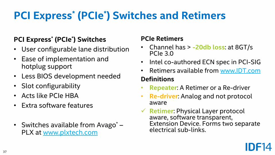
PCI Express* (PCIe*) Switches and Retimers
PCI Express* (PCIe*) Switches
• User configurable lane distribution
• Ease of implementation and hotplug support
• Less BIOS development needed
• Slot configurability
• Acts like PCIe HBA
• Extra software features
• Switches available from Avago* –PLX at www.plxtech.com
PCIe Retimers
• Channel has > -20db loss: at 8GT/s PCIe 3.0
• Intel co-authored ECN spec in PCI-SIG
• Retimers available from www.IDT.com
Definitions
• Repeater: A Retimer or a Re-driver
• Re-driver: Analog and not protocol aware
Retimer: Physical Layer protocol aware, software transparent, Extension Device. Forms two separate electrical sub-links.
38
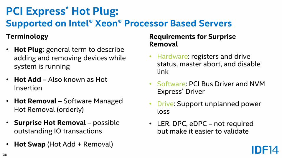
PCI Express* Hot Plug:Supported on Intel® Xeon® Processor Based Servers
Terminology
• Hot Plug: general term to describe adding and removing devices while system is running
• Hot Add – Also known as Hot Insertion
• Hot Removal – Software Managed Hot Removal (orderly)
• Surprise Hot Removal – possible outstanding IO transactions
• Hot Swap (Hot Add + Removal)
Requirements for Surprise Removal
• Hardware: registers and drive status, master abort, and disable link
• Software: PCI Bus Driver and NVM Express* Driver
• Drive: Support unplanned power loss
• LER, DPC, eDPC – not required but make it easier to validate
39
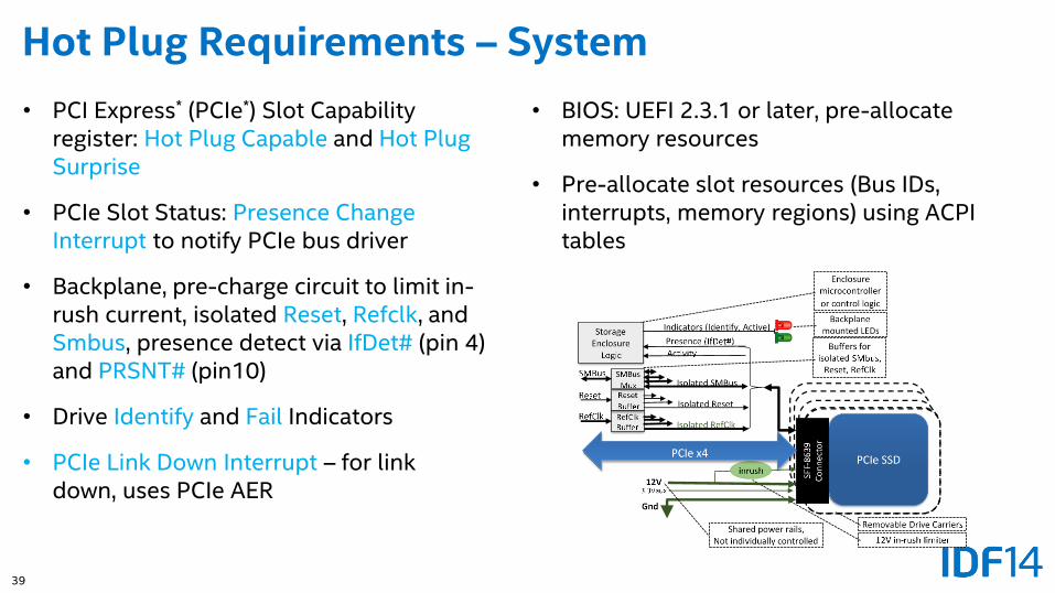
Hot Plug Requirements – System
• PCI Express* (PCIe*) Slot Capability register: Hot Plug Capable and Hot Plug Surprise
• PCIe Slot Status: Presence Change Interrupt to notify PCIe bus driver
• Backplane, pre-charge circuit to limit in-rush current, isolated Reset, Refclk, and Smbus, presence detect via IfDet# (pin 4) and PRSNT# (pin10)
• Drive Identify and Fail Indicators
• PCIe Link Down Interrupt – for link down, uses PCIe AER
• BIOS: UEFI 2.3.1 or later, pre-allocate memory resources
• Pre-allocate slot resources (Bus IDs, interrupts, memory regions) using ACPI tables