Embed Size (px)
DESCRIPTION
Citation preview

Version 6.20
SCANNER GUIDE

© 2012 by Anite Finland Ltd. All rights reserved.
This manual, as well as the software described in it, is furnished under license and may only be used or copied in accordance with the terms of such license. The information in this manual is intended for informational use only and is subject to change without notice. Anite Finland Ltd assumes no responsibility or liability for any errors or inaccuracies that may appear in this user manual.
Except as permitted by such license, no part of this publication may be reproduced or transmitted in any form or by any means, electronic, mechanical, recording, or otherwise, without the prior written permission of Anite Finland Ltd.
Windows®, Windows® XP, Windows® Vista, Windows® 7, Outlook®, and Internet Explorer are registered trademarks of the Microsoft® Corporation in the United States and other countries. MapInfo® and MapX® are registered trademarks of MapInfo® Corporation. CDMA 2000® is a registered trademark of the Telecommunications Industry Association (TIA -USA). The license management portion of this Licensed Technology is based on SentinelLM* © 1989-2003 Rainbow Technologies, Inc. All rights reserved.
Revision 6.20.01, Last edited February 2012

Nemo Scanner Guide 3
NEMO FSR1 5
CONNECTING NEMO FSR1 SCANNER 5 Changing the Nemo FSR1 IP Address 8 Connecting a GPS Antenna to Nemo FSR1 13
CONNECTING NEMO FSR1 SCANNER TO NEMO INVEX CHASSIS 14
STARTING NEMO FSR1 SCANNER 16
NEMO FSR1 FIRMWARE UPDATE 17
MEASURING WITH NEMO FSR1 SCANNER 18 Frequency Scanning 18 TOP-N Pilot Scanning - UMTS 20 TOP-N Pilot Scanning - CDMA/EVDO 23 TOP-N Pilot Scanning – LTE 24 Spectrum Analyzer Measurements 27 Band Scan 30
CALIBRATING NEMO FSR1 32
ANRITSU 33
CONNECTING ANRITSU SCANNERS 33 Connecting the Anritsu MS2721B DVB-H Analyzer/Anritsu MS2721B Spectrum Analyzer Scanner 37
STARTING ANRITSU SCANNERS 41
MEASURING WITH ANRITSU SCANNERS 42 Frequency Scanning 42 TOP-N Pilot Scanning - UMTS 45 Pilot Scrambling Code Scanning 51 DVB-H Scanning 53 Spectrum Analyzer Measurements 54
DRT 57
CONNECTING THE DRT WIMAX 4301A+ SCANNER 57
STARTING DRT SCANNERS 60
MEASURING WITH DRT SCANNERS 62 Frequency Scanning 62 Pilot Scanning 64
PCTEL 67
CONNECTING PCTEL LX CDMA/EVDO/GSM/WCDMA SCANNER 67
CONNECTING PCTEL EX SCANNERS 69 CONNECTING THE PCTEL LX GSM/WCDMA DUAL-MODE SCANNER 73
CONNECTING THE PCTEL MX SCANNER 76
CONNECTING PCTEL PCT SCANNERS 79
CONNECTING PCTEL SCANNERS TO NEMO INVEX CHASSIS 82
STARTING PCTEL SCANNERS 83 MEASURING WITH PCTEL SCANNERS 89

Nemo Scanner Guide 4
Frequency Scanning – PCTEL GSM/UMTS Scanners 89 Frequency Scanning – PCTEL EX LTE Scanner 91 Frequency Scanning – PCT GSM Scanner 93 Frequency Scanning – PCTEL CDMA/EVDO Scanners 95 TOP-N Pilot Scanning - UMTS 97 TOP-N Pilot Scanning – CDMA/EVDO 99 Spectrum Scanning 101 LTE OFDM Scanning 105 Pilot Scrambling Code Scanning 108
ROHDE & SCHWARZ 110
CONNECTING THE ROHDE & SCHWARZ TSMQ/TSML SCANNER 110 CONNECTING THE ROHDE & SCHWARZ TSMW SCANNER113
System Priority Order with R&S TSMW Scanners 115
CONNECTING ROHDE & SCHWARZ SCANNERS TO NEMO INVEX CHASSIS 117 Connecting R&S TSMW to Nemo Invex with an Ethernet Cable 118 Connecting R&S TSMW to Nemo Invex with a Network Switch 119
STARTING ROHDE & SCHWARZ SCANNERS 123
MEASURING WITH ROHDE & SCHWARZ SCANNERS 125 Frequency Scanning 125 TOP-N Pilot Scanning - UMTS 127 TOP-N Pilot Scanning - CDMA/EVDO 129 TOP-N Pilot Scanning - LTE 131 Spectrum Scanning 134
TROUBLESHOOTING SCANNERS 137
NEMO FSR1 137
Nemo FSR1 5
NEMO FSR1
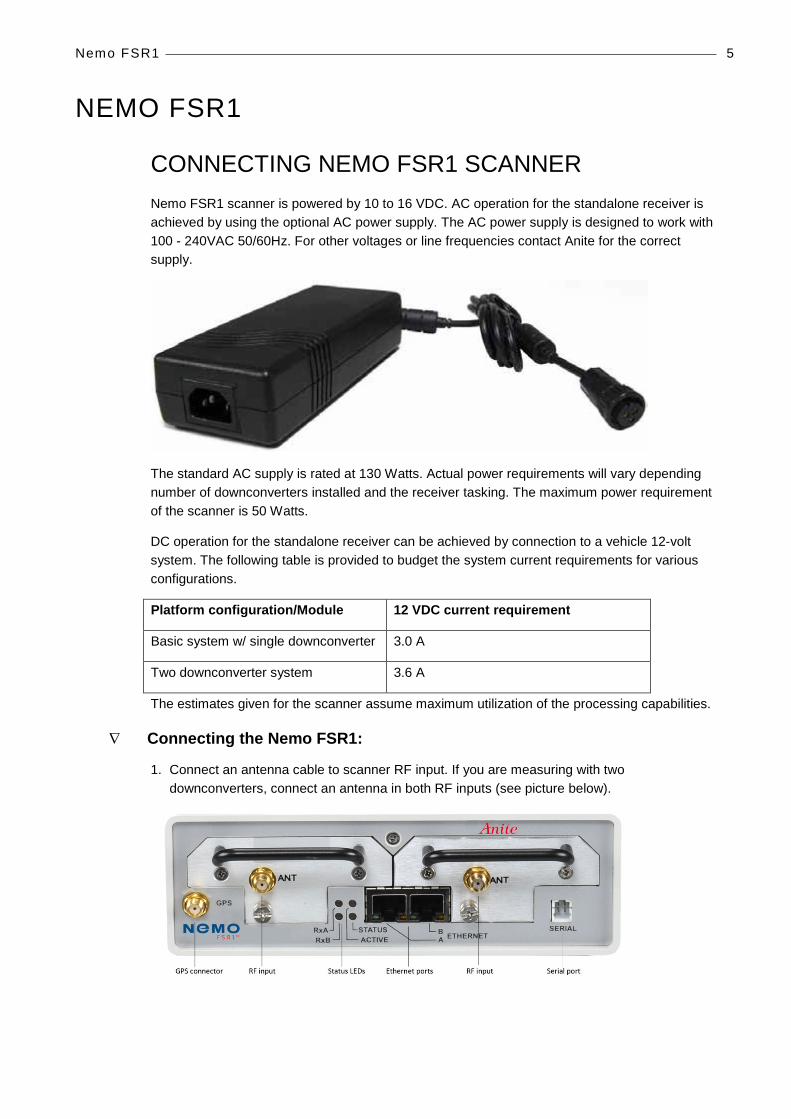
CONNECTING NEMO FSR1 SCANNER Nemo FSR1 scanner is powered by 10 to 16 VDC. AC operation for the standalone receiver is achieved by using the optional AC power supply. The AC power supply is designed to work with 100 - 240VAC 50/60Hz. For other voltages or line frequencies contact Anite for the correct supply.
The standard AC supply is rated at 130 Watts. Actual power requirements will vary depending number of downconverters installed and the receiver tasking. The maximum power requirement of the scanner is 50 Watts.
DC operation for the standalone receiver can be achieved by connection to a vehicle 12-volt system. The following table is provided to budget the system current requirements for various configurations.
Platform configuration/Module 12 VDC current requirement
Basic system w/ single downconverter 3.0 A
Two downconverter system 3.6 A
The estimates given for the scanner assume maximum utilization of the processing capabilities.
∇ Connecting the Nemo FSR1:
1. Connect an antenna cable to scanner RF input. If you are measuring with two downconverters, connect an antenna in both RF inputs (see picture below).

Nemo FSR1 6
2. Connect Ethernet cable(s) to the scanner Ethernet port(s) and to the Nemo Outdoor laptop.
3. Go to Control Panel | Network and Internet | Network and Sharing Center. Click on Change adapter settings.
4. Right-click on Local Area Connection and select Properties. In the Local Area Connection Properties dialog, select Internet Protocol Version 4 (TCP/IPv4) and click Properties.
Nemo FSR1 7
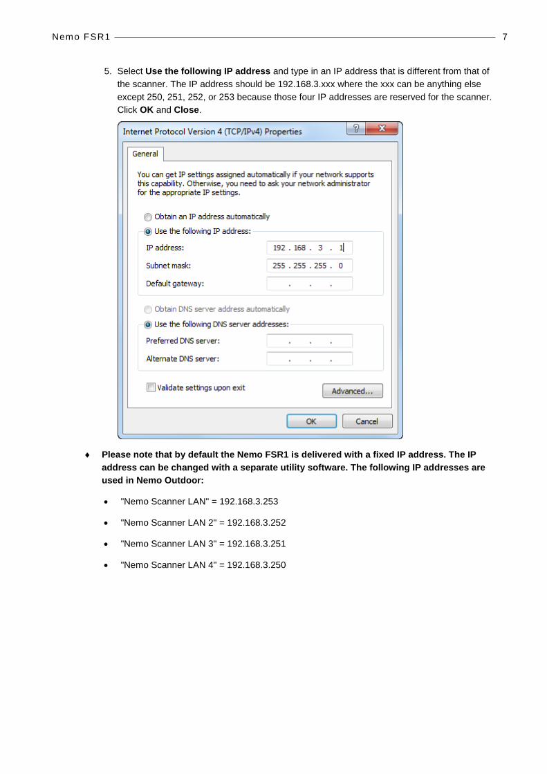
5. Select Use the following IP address and type in an IP address that is different from that of the scanner. The IP address should be 192.168.3.xxx where the xxx can be anything else except 250, 251, 252, or 253 because those four IP addresses are reserved for the scanner. Click OK and Close.
♦ Please note that by default the Nemo FSR1 is delivered with a fixed IP address. The IP address can be changed with a separate utility software. The following IP addresses are used in Nemo Outdoor:
• "Nemo Scanner LAN" = 192.168.3.253
• "Nemo Scanner LAN 2" = 192.168.3.252
• "Nemo Scanner LAN 3" = 192.168.3.251
• "Nemo Scanner LAN 4" = 192.168.3.250

Nemo FSR1 8
6. Connect the power cable to the scanner and to a power source. Switch power on.
7. The default address and name settings of the scanner are generally suitable for most users. There is no need to configure these settings when using the Nemo FSR1 scanner with Nemo Outdoor.
8. The status LEDs at the front panel display how the scanner is functioning.
LED Name LED Color Description RxA Green Receiver A enabled
Amber Receiver A disabled i.e. EEPROM not readable RxB Green Receiver B enabled
Amber Receiver B disabled i.e. EEPROM not readable Status Green GPS Locked
Amber GPS Unlocked Active Green Ethernet link connected
Red Ethernet link disconnected All LEDs Amber If all four LEDs are amber, the bootloader is
running and the module needs to be reloaded
Changing the Nemo FSR1 IP Address The default address and name settings of the Nemo FSR1 are generally suitable for most users. However, if you have two or more Nemo FSR1 scanners connected to the same measurement laptop, you will need to assign a different IP address for each scanner. By default, the Nemo FSR1 scanners are delivered with a fixed IP address: 192.168.3.253. When changing the IP address, please use the following IP addresses supported in Nemo Outdoor:
• "Nemo Scanner LAN" = 192.168.3.253
• "Nemo Scanner LAN 2" = 192.168.3.252
• "Nemo Scanner LAN 3" = 192.168.3.251
• "Nemo Scanner LAN 4" = 192.168.3.250
Fuse
Power connector Power switch
Fans
Nemo FSR1 9
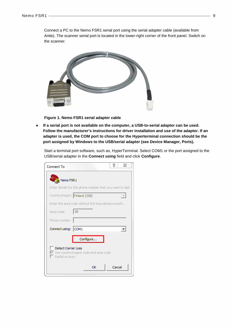
Connect a PC to the Nemo FSR1 serial port using the serial adapter cable (available from Anite). The scanner serial port is located in the lower-right corner of the front panel. Switch on the scanner.
Figure 1. Nemo FSR1 serial adapter cable
♦ If a serial port is not available on the computer, a USB-to-serial adapter can be used. Follow the manufacturer’s instructions for driver installation and use of the adapter. If an adapter is used, the COM port to choose for the Hyperterminal connection should be the port assigned by Windows to the USB/serial adapter (see Device Manager, Ports).
Start a terminal port software, such as, HyperTerminal. Select COM1 or the port assigned to the USB/serial adapter in the Connect using field and click Configure.

Nemo FSR1 10
In the COM1 Properties dialog, define the following settings:
Bits per second: 115200
Data bits: 8
Parity: None
Stop bits: 1
Flow control: Xon/Xoff
Click OK and OK. An empty HyperTerminal window is opened.

Nemo FSR1 11
Press Enter on your keyboard. The following information is displayed.
To change the IP address, press 2 and Enter. Enter the new IP address in format xxx.xxx.xxx.xxx. For example, 192.168.003.252. Press Enter.
Nemo FSR1 12
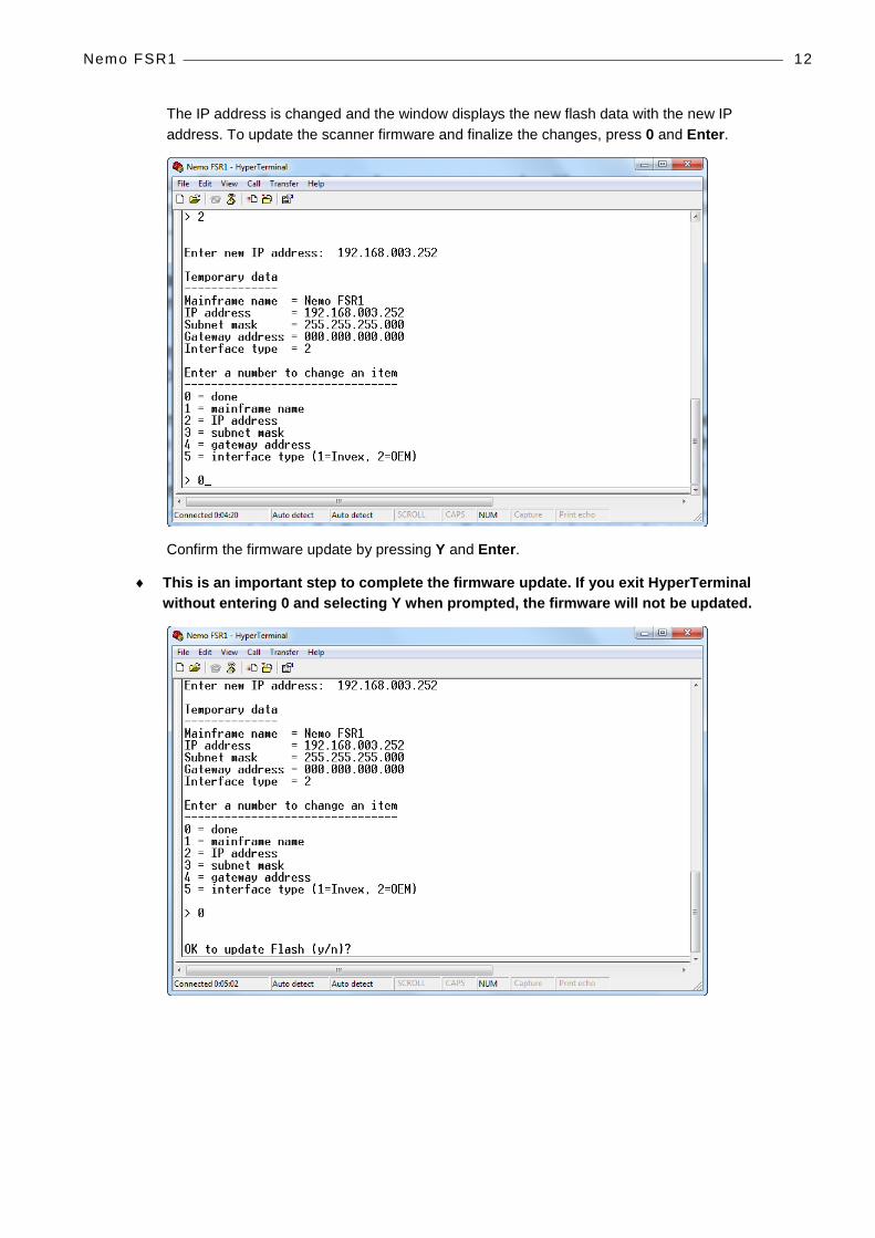
The IP address is changed and the window displays the new flash data with the new IP address. To update the scanner firmware and finalize the changes, press 0 and Enter.
Confirm the firmware update by pressing Y and Enter.
♦ This is an important step to complete the firmware update. If you exit HyperTerminal without entering 0 and selecting Y when prompted, the firmware will not be updated.
Nemo FSR1 13
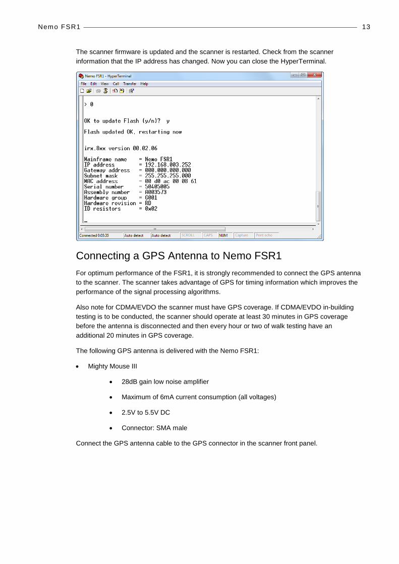
The scanner firmware is updated and the scanner is restarted. Check from the scanner information that the IP address has changed. Now you can close the HyperTerminal.
Connecting a GPS Antenna to Nemo FSR1 For optimum performance of the FSR1, it is strongly recommended to connect the GPS antenna to the scanner. The scanner takes advantage of GPS for timing information which improves the performance of the signal processing algorithms.
Also note for CDMA/EVDO the scanner must have GPS coverage. If CDMA/EVDO in-building testing is to be conducted, the scanner should operate at least 30 minutes in GPS coverage before the antenna is disconnected and then every hour or two of walk testing have an additional 20 minutes in GPS coverage.
The following GPS antenna is delivered with the Nemo FSR1:
• Mighty Mouse III
• 28dB gain low noise amplifier
• Maximum of 6mA current consumption (all voltages)
• 2.5V to 5.5V DC
• Connector: SMA male
Connect the GPS antenna cable to the GPS connector in the scanner front panel.

Nemo FSR1 14
CONNECTING NEMO FSR1 SCANNER TO NEMO INVEX CHASSIS Nemo FSR1 is connected to the Nemo Invex chassis (SI module) with an Ethernet cable. Ethernet ports are located on the front panel of the Nemo FSR1 scanner and on the front panel of the Nemo Invex SI module.
Nemo FSR1 front panel.
Nemo Invex SI module front panel.

Nemo FSR1 15
Nemo FSR1 power cable can be connected to the Nemo Invex chassis. The scanner power connector is located at the rear of the chassis.
The Nemo FSR1 scanner can be attached on top of the Nemo Invex chassis with a mounting plate.

Nemo FSR1 16
Clearance for air ventilation around the Nemo FSR1 is as follows:
• Back 10 cm
• Left side 3 cm
• Right side 3 cm (not applicable for Rev B scanner)
♦ Note that the air intake is on the left side and exhaust on the back.
STARTING NEMO FSR1 SCANNER 1. Start Nemo Outdoor. Do not load any previous device configuration if asked.
2. From the Measurement menu, select Add New Device.
3. Click on Scanner.
4. From the list select Nemo FSR1 and click Next.

Nemo FSR1 17
5. In the Scanner Properties dialog, select Nemo Scanner LAN as the Port and click OK.
6. If the dialog did not close, the startup did not succeed. Check the cable connections and the settings and try again.
7. If the Device Status window is not visible, open it from the View menu. A green light should be blinking. This means that the device is working properly and scanning using the default settings. If the status field displays, Device is not started, check that you are in online mode (click the Work Offline/Online button ). If the device is started but not scanning, check that you have selected channels to be scanned.
NEMO FSR1 FIRMWARE UPDATE Nemo FSR1 firmware can be updated using the Nemo FSR1 Firmware Update Utility or through Nemo Outdoor. For detailed information on using the update utility, please refer to the Nemo FSR1 Firmware Update Utility Instructions document.
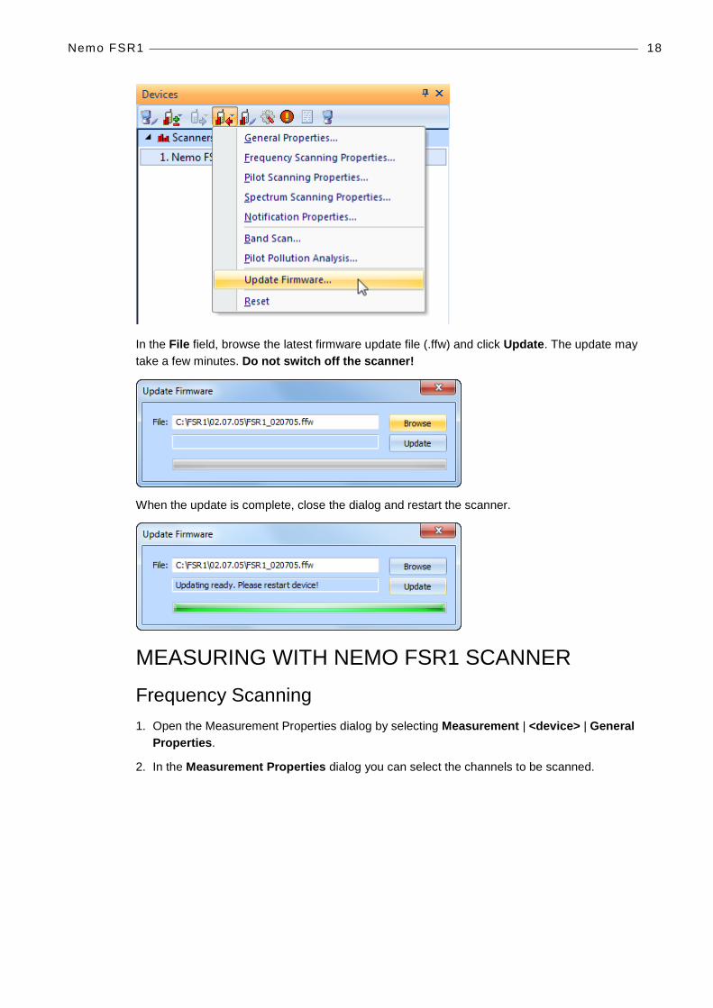
The scanner firmware can also be updated through Nemo Outdoor. Connect the scanner to Nemo Outdoor and then click the Measurement settings button in the Devices view. Select Update Firmware.
Nemo FSR1 18
In the File field, browse the latest firmware update file (.ffw) and click Update. The update may take a few minutes. Do not switch off the scanner!
When the update is complete, close the dialog and restart the scanner.
MEASURING WITH NEMO FSR1 SCANNER
Frequency Scanning 1. Open the Measurement Properties dialog by selecting Measurement | <device> | General
Properties.
2. In the Measurement Properties dialog you can select the channels to be scanned.

Nemo FSR1 19
3. On the Frequency scanning, GSM page, click the Select Channels button to select the GSM channels to be scanned.
Channel style defines the style of the measured channel. For GSM the option is 200 kHz.
Data mode defines the type of measurement data computed from each sample. Note that the available selection depends on the scanner type.
• RX Level Average: the data reported is the average RX level, in dB, of the number of samples.
Measurement period defines the time in milliseconds for which the scanner measures and then reports the result.
Sample size defines the number of samples taken from each channel before a measurement result is written to file.
Selecting the BSIC decoding option enables BSIC values and co-channel C/I measurements.
BSIC threshold defines the minimum BSIC level that the scanner reports.
Select the BCCH C/I option to activate BCCH decoding. Co-channel C/I is also enabled.
Cell information decoding. Mobile Network Code, Mobile Country Code and Cell ID information can be decoded from BCCH messages. Note that this is only enabled in online mode and if the option has been purchased with the scanner.

Nemo FSR1 20
When the System information decoding option is selected, L3 messages are written in the log file.
4. Click the Start Recording button to start recording the results in an output file.
TOP-N Pilot Scanning - UMTS Unknown Pilot scanning can be used for scanning unknown pilots or the strongest pilots. The Unknown Pilot Scan will from now on be referred to as TOP-N pilot mode/scanning.
∇ To set pilot scanning settings:
1. Open the Measurement Properties dialog by selecting Measurement | <device> | General Properties.
2. In the Measurement Properties dialog, go to the Pilot scanning page.
CPICH Ec/No threshold defines the minimum level for the CPICH Ec/No. If the values are below the threshold, the pilots are not reported.
Channel style refers to the style of the channel. For UMTS scanners, the options are Narrow Band (200kHz) and Wide Band (3.84MHz).
Correlator parameter is no longer utilized by the FSR1 UMTS scanning algorithms. It is encouraged to set this parameter to the highest correlation value, 4096.
Nemo FSR1 21
Data processing method defines how the scanned data is processed by the scanner. In aggregate method, the sum of all peak pilot Ec/Io values above the PN threshold is calculated. If there are no peaks above the PN threshold, value -30 dB is returned for WCDMA.
Measurement period defines the time in milliseconds for which the scanner measures and then reports the result.
Pilot measurement mode defines the measurement mode for pilot scanning.
• In High speed mode scanning speed is higher but sensitivity is lower. In high speed mode, weak pilots may be undetected.
• In High dynamic range mode scanning speed is lower but sensitivity is higher.
Top-N option enables/disables Top-N scrambling code scanning. If enabled, scanner will report results from N best scrambling codes. Number of pilots field defines how many pilots are reported by scanner in Top-N mode. The maximum number is 32.
Cell information decoding. Mobile Network Code, Mobile Country Code and Cell ID information can be decoded from BCCH messages. Note that this is only enabled in online mode and if the option has been purchased with the scanner.
Delay spread defines if the selected scanner will also measure the delay spread value (in chips) for each scanned scrambling code. Delay spread is determined as the difference between the last and first component to break the threshold set in PN Threshold.
P-SCH defines if the selected scanner will measure the P-SCH Ec/N0 value for each scrambling code.
S-SCH defines if the selected scanner will measure the S-SCH Ec/N0 value for each scrambling code.
The Top-N Configuration button will open the Select Channels dialog where you can select channels for pilot scanning.

Nemo FSR1 22
∇ To select channels:
1. In the Measurement Properties, Pilot scanning, UMTS page, click the Top-N Configuration button. The Select Channels dialog is opened.
2. The table displays the channel numbers, not the frequencies.
3. You can remove channels from the Selected list by selecting a channel and clicking the Remove button.
4. You can add channels to the Selected list by selecting a channel from the Available list and clicking the Add button.
5. Click OK to return to the Measurement Properties dialog.
6. After making the appropriate settings, click OK and OK again and go to online mode to start the scanning.
7. A green light on the scanner Device Status window should start blinking. This means that the device is working properly and scanning using the default settings. In TOP-N Mode this may take a few seconds.
8. Click the Start Recording button to start recording the results in an output file.

Nemo FSR1 23
TOP-N Pilot Scanning - CDMA/EVDO ♦ Note that the EVDO measurements can only be performed in a proper way when a
CDMA2000 channel is measured as well. In this way, the time relationship between the different PN offsets is resolved.
1. Open the Measurement Properties dialog by selecting Measurement | <device> | General Properties.
2. In the Measurement Properties dialog, go to the Pilot scanning, CDMA page.
Channel style refers to the style of the channel. For UMTS scanners, the options are Narrow Band (200kHz) and Wide Band (3.84MHz).
Correlator affects how the scanner works. Bigger correlator size enables the scanner to detect and measure pilot channels with better dynamic but makes scanning speed slower. For example, when using correlator size 2048 versus 512, the dynamic range for pilot measurement changes from –21db to –17db.
Data processing method defines how the scanned data is processed by the scanner. In aggregate method, the sum of all peak pilot Ec/Io values above the PN threshold is calculated. If there are no peaks above the PN threshold, value -30 dB is returned for WCDMA.
Pilot Ec/I0 threshold defines the threshold level for the pilot Ec/I0. If the values are below the threshold, the pilots are not scanned.

Nemo FSR1 24
Top-N mode option enables/disables TOP-N scrambling code scanning. Number of pilots field defines how many pilots are reported by the scanner in TOP-N mode.
The Top-N Configuration button will open the Select Channels dialog where you can select channels for pilot scanning.
♦ Note that the Nemo FSR1 scanner supports a max of 90 cell IDs.
3. After making the appropriate settings, click OK and OK again and go to online mode to start the scanning.
4. A green light on the scanner Device Status window should start blinking. This means that the device is working properly and scanning using the default settings. In TOP-N Mode this may take a few seconds.
5. Click the Start Recording button to start recording the results in an output file.
TOP-N Pilot Scanning – LTE 1. Open the Measurement Properties dialog by selecting Measurement | <device> | General
Properties.
2. Go to the Pilot scanning, LTE page to define LTE-specific pilot scanning settings.

Nemo FSR1 25
Channel style refers to the style of the channel. For UMTS scanners, the options are Narrow Band (200kHz) and Wide Band (3.84MHz).
Data processing method defines how the scanned data is processed by the scanner. In aggregate method, the sum of all peak pilot Ec/Io values above the PN threshold is calculated. If there are no peaks above the PN threshold, value -30 dB is returned for WCDMA.
CINR refers to the Carrier to Interference and Noise ratio value, in dB *100 (e.g., -16.34). It is based on the requested reuse factor.
Time offset refers to the number of samples between P-SCH Primary Synchronization Signal arrival time with respect to receiver frequency reference that is derived from GPS reference time.
Sync signal refers to the ratio between the synchronization channel, i.e., primary and secondary signal received power and the interference and noise from the same synchronization signal set.
Reference signal refers to the ratio between the reference signal received power (RSRP) and the interference and noise from the same reference signal set.
When the System information decoding option is selected, L3 messages are written in the log file.
The Select Channels button will open the Select Channels dialog where you can select channels for pilot scanning.
When you select LTE channels, you can also define some channel-specific settings. In the LTE Channel Specific Settings dialog, select the channel from the Selected channels list and define the settings.
♦ Note that the available options are device specific.
Nemo FSR1 26
Cyclic prefix defines the type of signal the scanner is set to measure. With Autodetect selected, the scanner will automatically detect the appropriate signal type. If Cyclic Prefix is known to be Normal (most common), setting the scanner to Normal will increase scanning speed slightly.
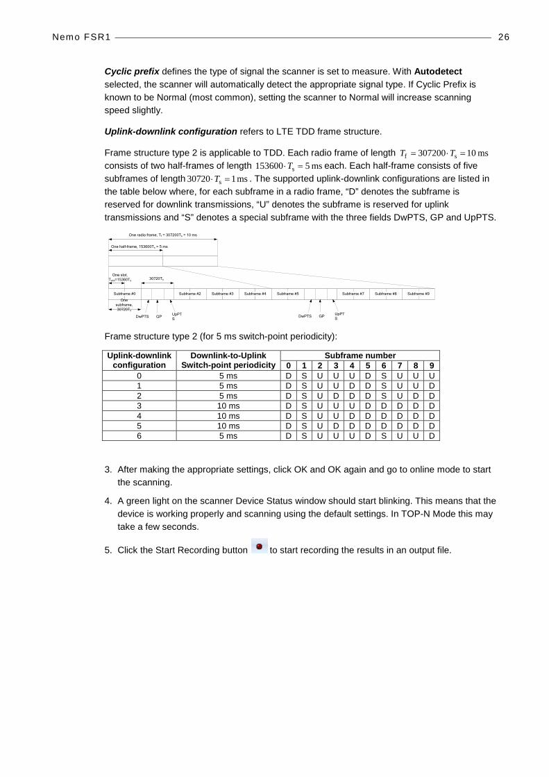
Uplink-downlink configuration refers to LTE TDD frame structure.
Frame structure type 2 is applicable to TDD. Each radio frame of length ms 10307200 sf =⋅= TT consists of two half-frames of length ms 5153600 s =⋅T each. Each half-frame consists of five subframes of length ms 107203 s =⋅T . The supported uplink-downlink configurations are listed in the table below where, for each subframe in a radio frame, “D” denotes the subframe is reserved for downlink transmissions, “U” denotes the subframe is reserved for uplink transmissions and “S” denotes a special subframe with the three fields DwPTS, GP and UpPTS.
One slot, Tslot=15360Ts
GP UpPTSDwPTS
One radio frame, Tf = 307200Ts = 10 ms
One half-frame, 153600Ts = 5 ms
30720Ts
One subframe, 30720Ts
GP UpPTSDwPTS
Subframe #2 Subframe #3 Subframe #4Subframe #0 Subframe #5 Subframe #7 Subframe #8 Subframe #9
Frame structure type 2 (for 5 ms switch-point periodicity):
Uplink-downlink configuration
Downlink-to-Uplink Switch-point periodicity
Subframe number 0 1 2 3 4 5 6 7 8 9
0 5 ms D S U U U D S U U U 1 5 ms D S U U D D S U U D 2 5 ms D S U D D D S U D D 3 10 ms D S U U U D D D D D 4 10 ms D S U U D D D D D D 5 10 ms D S U D D D D D D D 6 5 ms D S U U U D S U U D
3. After making the appropriate settings, click OK and OK again and go to online mode to start the scanning.
4. A green light on the scanner Device Status window should start blinking. This means that the device is working properly and scanning using the default settings. In TOP-N Mode this may take a few seconds.
5. Click the Start Recording button to start recording the results in an output file.
Nemo FSR1 27
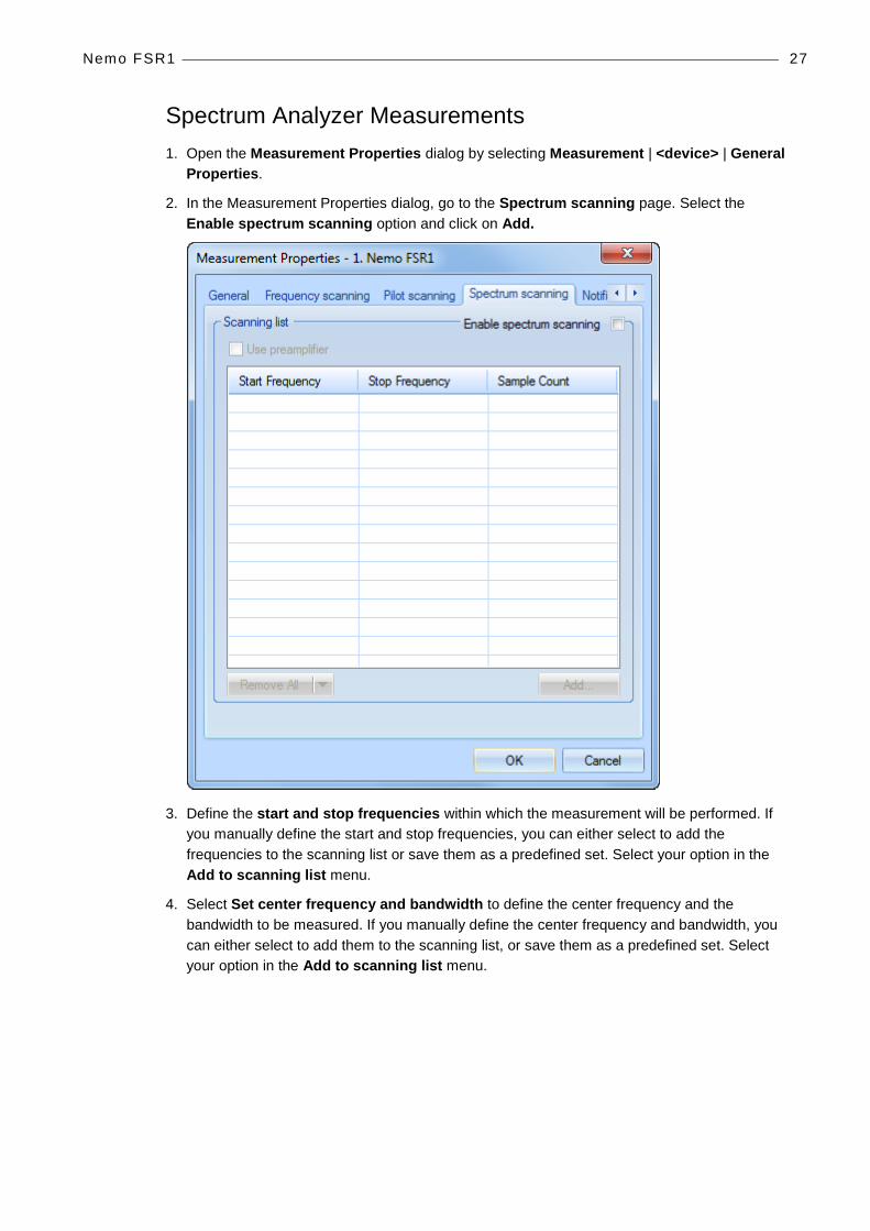
Spectrum Analyzer Measurements 1. Open the Measurement Properties dialog by selecting Measurement | <device> | General
Properties.
2. In the Measurement Properties dialog, go to the Spectrum scanning page. Select the Enable spectrum scanning option and click on Add.
3. Define the start and stop frequencies within which the measurement will be performed. If you manually define the start and stop frequencies, you can either select to add the frequencies to the scanning list or save them as a predefined set. Select your option in the Add to scanning list menu.
4. Select Set center frequency and bandwidth to define the center frequency and the bandwidth to be measured. If you manually define the center frequency and bandwidth, you can either select to add them to the scanning list, or save them as a predefined set. Select your option in the Add to scanning list menu.

Nemo FSR1 28
♦ If the requested frequency range is not supported by the device, Nemo Outdoor automatically adjusts the frequency range for the device, and only frequency ranges supported by the scanning receiver are used to perform spectrum analyzer measurements.
♦ Based on the start and stop frequency and the number of samples (points), Nemo Outdoor calculates the correct resolution bandwidth (RBW). It should be noted that resolution bandwidths with Nemo FSR1 scanners are fixed. The currently supported values are: 1875, 3750, 7500, 15000, 30000, 60000 and 120000 Hz. Nemo Outdoor automatically selects the closest RBW to be used.

Nemo FSR1 29
5. You can add scanning sets in the Predefined scanning sets field through the Add to Scanning List button. Click the arrow in the button and select Save as Predefined Set. Define a name in the Enter Frequency Set Name field and click OK.
6. The name appears in the Predefined scanning sets field along with the chosen frequency and/or bandwidth information selected in the Reporting field.
7. After making the appropriate settings, click OK and OK again and go to online mode to start the scanning.
8. A green light on the scanner Device Status window should start blinking. This means that the device is working properly and scanning using the default settings.
9. Click the Start Recording button to start recording the results in an output file.

Nemo FSR1 30
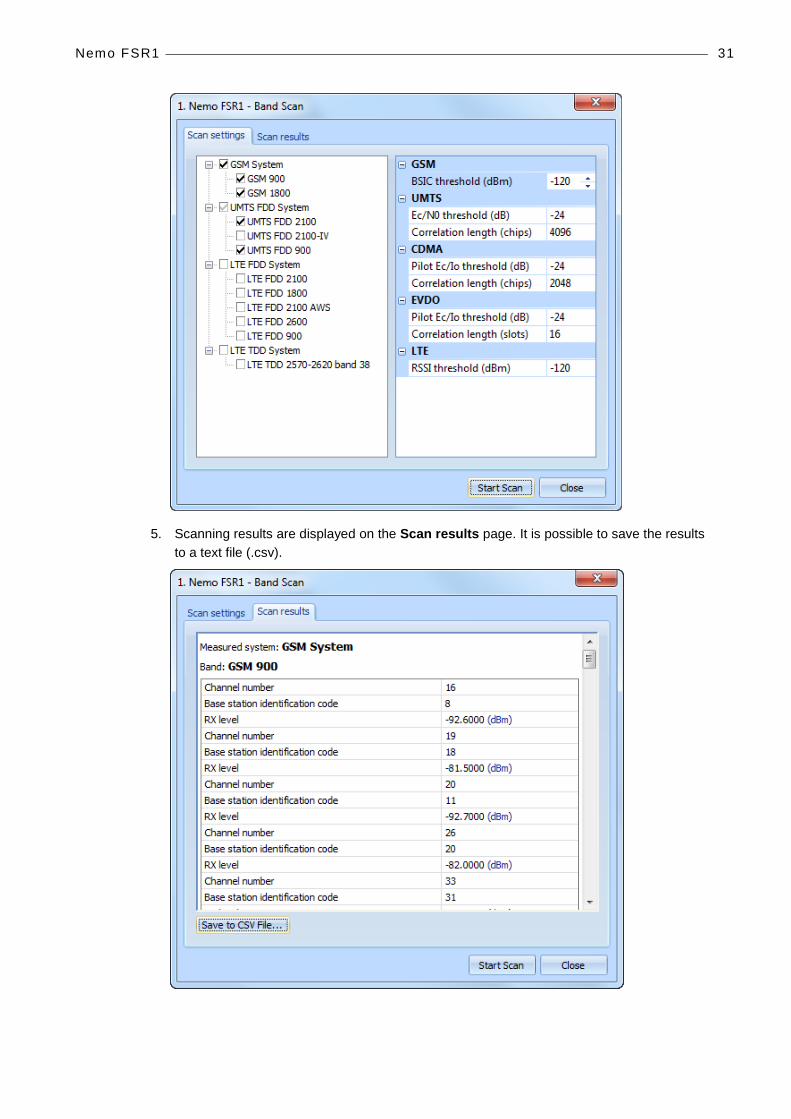
Band Scan With the Nemo FSR1 scanner you can perform band scanning. All specified channels are scanned for the selected band and technology and the strongest measured identifiers (CDMA PN, EVDO PN, WCDMA SC, LTE Cell ID) for every valid channel of that technology type are reported. Signal strength and signal quality are reported for each identified channel. This feature is useful in areas where broadcasted technologies and bands are unknown.
1. To start a band scan, right click the Nemo FSR1 item in the Devices view and select Band Scan.
2. Available technologies and bands supported by the scanner are shown under Scan settings. Please note that only licensed technologies (systems) are shown.
3. Select the technologies and bands that you want to be scanned and define the threshold levels for the parameters available.
4. Finally press the Start Scan button. With the default threshold values it takes approximately two minutes and 30 seconds to scan GSM 900, 1800 and WCDMA 2100 bands. The scanning rate can be increased by adjusting the threshold values.
Nemo FSR1 31
5. Scanning results are displayed on the Scan results page. It is possible to save the results to a text file (.csv).

Nemo FSR1 32
CALIBRATING NEMO FSR1 Self-test runs every time the handler is started and notifications are sent to the user interface depending on the calibration results. Self-test results can be viewed in the Nemo Outdoor Output window.
• Test passed
• No action required. Indicates that there are no known issues with receiver/down converter module calibration.
• Calibration warning
• Measured noise level indicates that the down converter is functioning but may be at or approaching calibration limits. Recommended that the down converter is calibrated as soon as possible. Please contact Nemo helpdesk or local sales representative to arrange re-calibration.
• Test failure
• Measured noise levels are significantly out of range and down converter is not functioning correctly. Recommended that the down converter be returned immediately for factory assessment, potential repair, and calibration. Please contact Nemo helpdesk or local sales representative to arrange service for the unit.
Anr itsu 33
ANRITSU
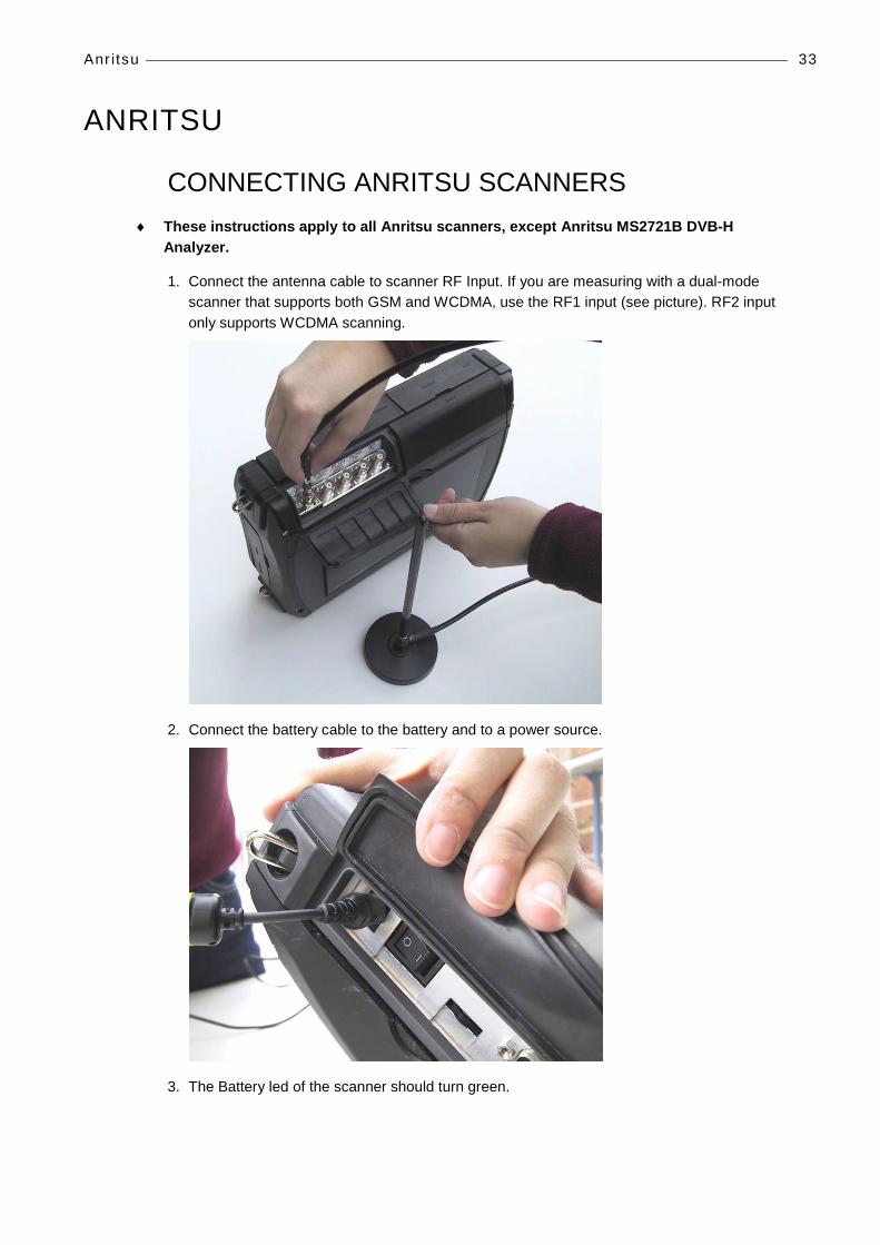
CONNECTING ANRITSU SCANNERS ♦ These instructions apply to all Anritsu scanners, except Anritsu MS2721B DVB-H
Analyzer.
1. Connect the antenna cable to scanner RF Input. If you are measuring with a dual-mode scanner that supports both GSM and WCDMA, use the RF1 input (see picture). RF2 input only supports WCDMA scanning.
2. Connect the battery cable to the battery and to a power source.
3. The Battery led of the scanner should turn green.

Anr itsu 34
♦ The following steps apply to Anritsu ML8720B and ML8720C scanners. If you are measuring with the Anritsu ML8740A or Anritsu ML8740B scanner, see step 12.
4. Connect the null modem cable to the scanner COM port that can be found below the power switch.
5. Connect the null modem to one of the PC COM ports
6. Turn the power on in the scanner. The Power led should light up.
7. The scanner should now start, wait until the scanner has started
8. Press the Menu button in the scanner.
9. Use the arrow keys and the Sel button to select Interface and Behavior.
10. Check that the settings are as follows. If not, change them using the arrow keys and the Sel button (note that the selected item will be underlined as soon as you use the arrow buttons to switch to another line). To exit the dialog without saving, press the F4 button (Cancel). To exit the dialog and save the modified settings, press the F5 button (OK).
• COM1 Protocol: Direct
• COM1 Baud Rate: 38400 or 57600 or 115200
• COM1 Stop Bit(s): 1
• COM1 Data Length: 8
• COM1 Parity: None
♦ The baud rate 115200 is the fastest option.
♦ Note! Memorize the baud rate. It is needed when starting the device.

Anr itsu 35
11. If you are measuring with the Anritsu ML8740A or Anritsu ML8740B scanner, see the following steps.
12. Insert the Anritsu installation CD in your PC.
13. Connect the USB cable to the scanner USB port found in the front panel and to the PC.
14. Switch the scanner on.
15. The New Hardware Wizard will start automatically. Select the No, not this time option and click Next.
16. Select the Install the software automatically option and click Next.
Anr itsu 36
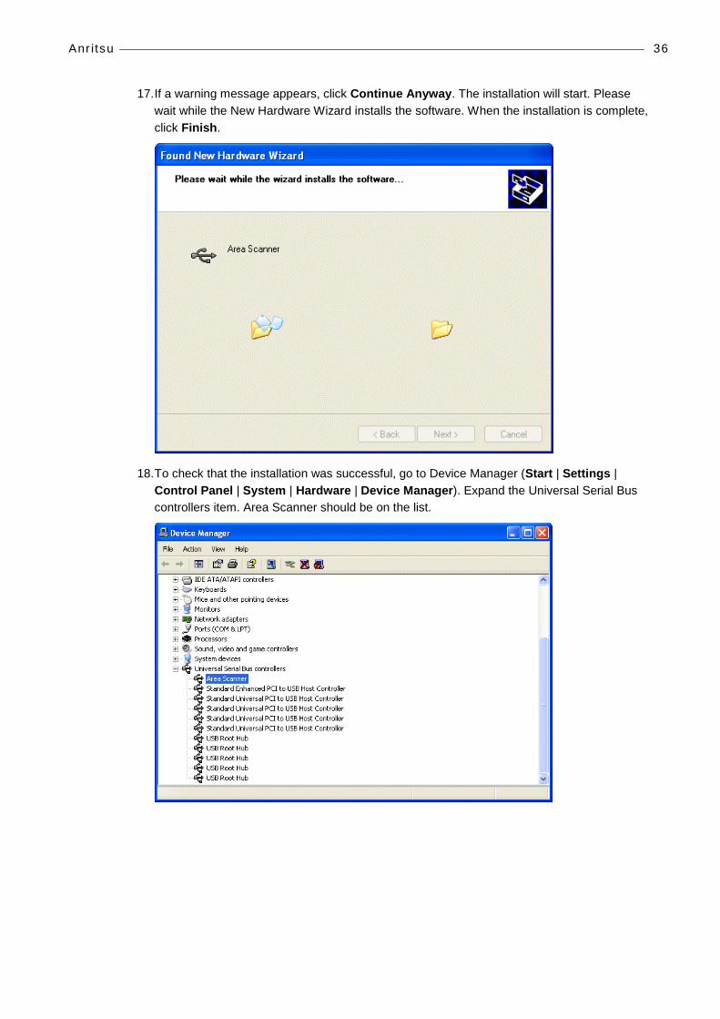
17. If a warning message appears, click Continue Anyway. The installation will start. Please wait while the New Hardware Wizard installs the software. When the installation is complete, click Finish.
18. To check that the installation was successful, go to Device Manager (Start | Settings | Control Panel | System | Hardware | Device Manager). Expand the Universal Serial Bus controllers item. Area Scanner should be on the list.

Anr itsu 37
19. Double-click on Area Scanner. Check that the Device Status field displays This device is working properly. Exit the dialog by clicking OK.
Connecting the Anritsu MS2721B DVB-H Analyzer/Anritsu MS2721B Spectrum Analyzer Scanner 1. To install the device drivers the user must have administrative rights to its PC, and the Take
ownership of files or other objects policy has to be enabled for this user on this PC.
2. Copy the executable file visa400full.exe to your local drive before installing the driver, and run the installation from the hard drive.
3. Double-click on the file and unzip the contents to your hard-drive. This may take a couple of minutes.
4. The installation starts automatically.
5. Click Next>> on the welcome page.
Anr itsu 38
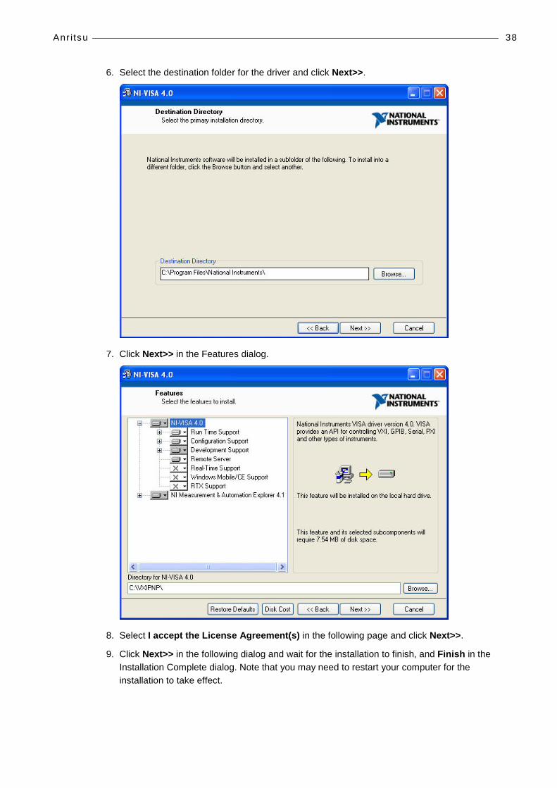
6. Select the destination folder for the driver and click Next>>.
7. Click Next>> in the Features dialog.
8. Select I accept the License Agreement(s) in the following page and click Next>>.
9. Click Next>> in the following dialog and wait for the installation to finish, and Finish in the Installation Complete dialog. Note that you may need to restart your computer for the installation to take effect.

Anr itsu 39
10. Connect the scanner with your PC through a network cable. Insert one end of the network cable in the network cable connector in the scanner, and the other end to the network cable connector in your PC.
11. Next, you need to make some changes to your PC’s network card properties. Go to Start | Control Panel | Network Connections, and right-click on Local Area Connection, and select Properties. In the Local Area Connection Properties dialog, select Internet Protocol (TCP/IP) and click on Properties. Select Use the following IP address. You need to type in an IP address out of the range 192.168.0.11 - 192.168.0.14, as those addresses are reserved for the scanner. Type in, for example, 192.168.0.10. Next, type 255.255.0.0 in the Subnet mask field. Click OK and Close to exit the dialogs.
12. Next, start the scanner by pressing on the green On/Off button.
13. Press on Shift and then System (8) button on the scanner.
14. On the menu to the right of the screen, select System Options | Ethernet Config by using the grey buttons next to the screen.
Anr itsu 40
15. Select the Set the IP Address Manually using the following Settings by pressing the top-most grey button immediately under the Esc button.
16. Type in the same IP address for both IP and Gateway from those reserved for the scanner (192.168.0.11 - 192.168.0.14). Here the selected IP address will be 192.168.0.14. You can move to different directions on the screen through the grey buttons. If the Subnet field is not automatically filled when filling the IP and Gateway fields, you can use, for example, 255.255.255.255 for it. Press Enter and restart the device by clicking twice on the On/Off button.
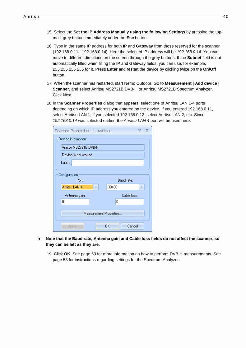
17. When the scanner has restarted, start Nemo Outdoor. Go to Measurement | Add device | Scanner, and select Anritsu MS2721B DVB-H or Anritsu MS2721B Spectrum Analyzer. Click Next.
18. In the Scanner Properties dialog that appears, select one of Anritsu LAN 1-4 ports depending on which IP address you entered on the device. If you entered 192.168.0.11, select Anritsu LAN 1, if you selected 192.168.0.12, select Anritsu LAN 2, etc. Since 192.168.0.14 was selected earlier, the Anritsu LAN 4 port will be used here.
♦ Note that the Baud rate, Antenna gain and Cable loss fields do not affect the scanner, so they can be left as they are.
19. Click OK. See page 53 for more information on how to perform DVB-H measurements. See page 53 for instructions regarding settings for the Spectrum Analyzer.
Anr itsu 41
STARTING ANRITSU SCANNERS 1. Start Nemo Outdoor. Do not load any previous device configuration if asked.
2. From the Measurement menu, select Add New Device.
3. Click on Scanner.
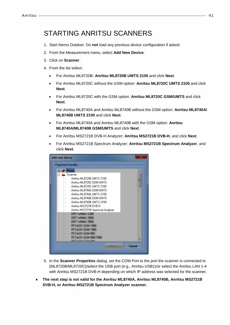
4. From the list select:
• For Anritsu ML8720B: Anritsu ML8720B UMTS 2100 and click Next.
• For Anritsu ML8720C without the GSM option: Anritsu ML8720C UMTS 2100 and click Next.
• For Anritsu ML8720C with the GSM option: Anritsu ML8720C GSM/UMTS and click Next.
• For Anritsu ML8740A and Anritsu ML8740B without the GSM option: Anritsu ML8740A/ ML8740B UMTS 2100 and click Next.
• For Anritsu ML8740A and Anritsu ML8740B with the GSM option: Anritsu ML8740A/ML8740B GSM/UMTS and click Next.
• For Anritsu MS2721B DVB-H Analyzer: Anritsu MS2721B DVB-H, and click Next.
• For Anritsu MS2721B Spectrum Analyzer: Anritsu MS2721B Spectrum Analyzer, and click Next.
5. In the Scanner Properties dialog, set the COM Port to the port the scanner is connected to (ML8720B/ML8720C)/select the USB port (e.g., Anritsu USB1)/or select the Anritsu LAN 1-4 with Anritsu MS2721B DVB-H depending on which IP address was selected for the scanner.
♦ The next step is not valid for the Anritsu ML8740A, Anritsu ML8740B, Anritsu MS2721B DVB-H, or Anritsu MS2721B Spectrum Analyzer scanner.

Anr itsu 42
6. Set the baud rate to the one used by the scanner and click OK. Note that the baud rate must be the same that you chose when you were connecting the scanner. The dialog will be closed and the scanner should now be connected to the system.
7. If the dialog did not close, the startup did not succeed. Check the cable connections and the settings and try again.
8. If the Device Status window is not visible, open it from the View menu. A green light should be blinking. This means that the device is working properly and scanning using the default settings. If the status field displays, Device is not started, check that you are in online mode (click the Work Offline/Online button ).
MEASURING WITH ANRITSU SCANNERS
Frequency Scanning 1. Open the Measurement Properties dialog by selecting Measurement | <device> | General
Properties.
2. In the Measurement Properties dialog you can select the channels to be scanned:
• If the scanner supports only one carrier, you can select either GSM or UMTS channels to be scanned.
• If the scanner supports two carriers, you can select for scanning both GSM and UMTS channels. If you select GSM channels, you can select a maximum of one UMTS channel. If you do not select GSM channels, you can select one or two UMTS channels.
3. On the Frequency scanning, GSM page, click the Select Channels button to select the GSM channels to be scanned.

Anr itsu 43
♦ Note that the scanner reports the 32 strongest channels from the selected GSM channels.
Channel style defines the style of the measured channel. For GSM the options are 200 kHz and 30 kHz narrow.
Data mode defines the type of measurement data computed from each sample. Note that the available selection depends on the scanner type.
• RX Level Average: the data reported is the average RX level, in dB, of the number of samples.
• RX Level Maximum: the data reported is the maximum RX level, in dB, of the number of samples.
• RX Level Minimum: the data reported is the minimum RX level, in dB, of the number of samples.
• RX Level Standard Deviation: the data reported is the standard of deviation of the number of samples reported as an integer.
• RX Level 10%: the data reported is the 10th percentile RX level, in dB, of the number of samples.
• RX Level 50%: the data reported is the 50th percentile RX level, in dB, of the number of samples.

Anr itsu 44
• RX Level 90%: the data reported is the 90th percentile RX level, in dB, of the Number of samples.
Measurement period defines the time in milliseconds for which the scanner measures and then reports the result.
Sample size defines the number of samples taken from each channel before a measurement result is written to file.
Selecting the BSIC decoding option displays BSIC value in a measurement window.
BSIC Threshold defines the minimum BSIC level that the scanner reports.
BCCH C/I option is available with PCTEL and Rohde&Schwarz GSM scanners only.
4. Click the Start Recording button to start recording the results in an output file.

Anr itsu 45
TOP-N Pilot Scanning - UMTS Unknown Pilot scanning can be used for scanning unknown pilots or the strongest pilots. The Unknown Pilot Scan will from now on be referred to as TOP-N Pilot Mode/Scanning.
∇ To set pilot scanning settings:
1. Open the Measurement Properties dialog by selecting Measurement | <device> | General Properties.
2. In the Measurement Properties dialog, go to the Pilot scanning page.
♦ Note that some of the options are enabled/disabled in this dialog according to the selected scanner model.
Channel style refers to the style of the channel. For UMTS scanners, the options are Narrow Band (200kHz) and Wide Band (3.84MHz). For Anritsu scanners, only Wide Band is available.
Data processing method defines how the scanned data is processed by the scanner. In aggregate method, the sum of all peak pilot Ec/Io values above the PN threshold is calculated. If there are no peaks above the PN threshold, value -30 dB is returned for WCDMA.
Measurement period defines the time in milliseconds for which the scanner measures and then reports the result.
Anr itsu 46
Number of fingers defines the maximum number of fingers used for RAKE in measurement.
Selective level determines a valid path. Set a value (in dB) to decide a valid path from the noise floor (average value).
Rake threshold determines a valid path (in dB). Subtracting the set value from a path with a maximum correlation value gives the lower limit of the valid path.
Top-N option enables/disables Top-N scrambling code scanning. If enabled, scanner will report results from N best scrambling codes. Number of pilots field defines how many pilots are reported by scanner in Top-N mode.
Delay profile option enables/disables delay profile scanning. The Channel number field provides a list of channels that can be selected for scanning.
Finger option enables and disables Finger measurements for the scanner.
P-SCH defines if the selected scanner will measure the P-SCH Ec/N0 value for each scrambling code.
SIR (signal to interference ratio) defines if the selected scanner will measure the SIR value for each scrambling code.
S-SCH defines if the selected scanner will measure the S-SCH Ec/N0 value for each scrambling code.
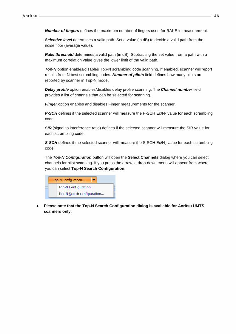
The Top-N Configuration button will open the Select Channels dialog where you can select channels for pilot scanning. If you press the arrow, a drop-down menu will appear from where you can select Top-N Search Configuration.
♦ Please note that the Top-N Search Configuration dialog is available for Anritsu UMTS scanners only.

Anr itsu 47
In the Top-N Search Configuration dialog you can limit the search performed by the scanner and consequently speed up the search.
Group specifies the group number for the primary scrambling code in the range of 0 to 63.
Cell specifies the cell number for the primary scrambling code in the range of 0 to 7.
Secondary code specifies the secondary scrambling code. Limit range should be set from 0 to 0.
Channelization code specifies the channelization code. Limit range should be set from 0 to 0.
Search method defines how the search is performed. P-CPICH (primary common pilot channel) searches with P-CPICH. SCH performs a three-step search with P-SCH and S-SCH.
∇ To select pilot parameters:
1. Select the TOP-N Mode option.
2. Set the Number of Scrambling codes value. This defines how many strongest pilots are to be reported by the scanner. The maximum is 32 pilots.

Anr itsu 48
∇ To select channels:
1. In the Measurement Properties, Pilot scanning, UMTS page, click the Top-N Configuration button. The Select Channels dialog is opened.
2. The table displays the channel numbers, not the frequencies.
♦ With the Anritsu ML8720B single carrier scanner only one channel can be selected. If you are measuring with the Anritsu ML8720B-03 dual carrier scanner, two channels can be selected.
3. You can remove channels from the Selected list by selecting a channel and clicking the Remove button.
4. You can add channels to the Selected list by selecting a channel from the Available list and clicking the Add button.
5. Click OK to return to the Measurement Properties dialog.

Anr itsu 49
∇ To select search parameters:
1. Open the Measurement Properties, Pilot scanning, UMTS page. Press down the Top-N Configuration button and select Top-N Search Configuration.
2. The Top-N Search Configuration dialog opens.

Anr itsu 50
3. Set the Group search range. The group number is the scrambling code divided by 8. For example, SC (scrambling code) 12 = group 1, cell 4.
4. Set the Cell search range. The cell number is the division modulus. For example, SC (scrambling code) 12 = group 1, cell 4.
5. The Secondary Code and the Channelization Code ranges should be set from 0 to 0 for scanning only the P-CPICH.
6. Select the Search Method. SCH means that the P-CPICH are searched using P-SCH and S-SCH. P-CPICH means that the P-CPICH are searched without using P-SCH and S-SCH.
♦ Note that the P-CPICH method is much slower than the SCH method.
7. Click OK to accept the settings and to return to the Measurement Properties dialog.
8. Data processing method defines how the scanner will process samples before reporting.
9. PN threshold defines the limit above which Ec/N0 peaks must go if Aggregated data processing method is used.
♦ In pilot scanning mode, the RSSI is always measured for each channel.
♦ In pilot scanning mode the P-CPICH Ec/N0 and RSCP are always measured for each scrambling code.
10. After making the appropriate settings, click OK and OK again and go to online mode to start the scanning.
11. A green light on the scanner Device Status window should start blinking. This means that the device is working properly and scanning using the default settings. In TOP-N Mode this may take a few seconds.
12. Click the Start Recording button to start recording the results in an output file.

Anr itsu 51
Pilot Scrambling Code Scanning Pilot Scrambling Code Scanning or Known Scrambling Code Scanning can be used to scan known pilots. The Known Scrambling Code Scanning will from now on be referred to as Normal Pilot Mode.
1. Open the Measurement Properties dialog by selecting Measurement | <device> | General Properties.
1. Go to the Measurement Properties, Pilot scanning, UMTS page .
2. Clear the TOP-N mode option and click the Select Channels button. The Select Scrambling Codes dialog is opened.
3. Select channels in the Selected channel numbers table by clicking the Select button.
♦ With the Anritsu ML8720B single carrier scanner only one channel can be selected. If you are measuring with the Anritsu ML8720B-03 dual carrier scanner, two channels can be selected.
4. For each selected channel, select scrambling codes. Select a channel and click the Select button below the Selected scrambling codes table.
5. Click OK to return to the Measurement Properties dialog.
Anr itsu 52
6. When using an Anritsu scanner in Pilot Scanning mode, you can define the measurement period. It defines the time period from which results are gathered and processed before reporting.
7. Data processing method defines how the scanner will process samples before reporting.
♦ In Pilot Scanning Mode the RSSI is always measured for each channel.
♦ In Pilot Scanning Mode the P-CPICH Ec/N0 and RSCP are always measured for each scrambling code.
8. After making the appropriate settings, click OK and OK again and go to online mode to start the scanning.
9. A green light on the scanner Device Status window should start blinking. This means that the device is working properly and scanning using the default settings. In TOP-N Mode this may take a few seconds.
10. Click the Start Recording button to start recording the results in an output file.
Anr itsu 53
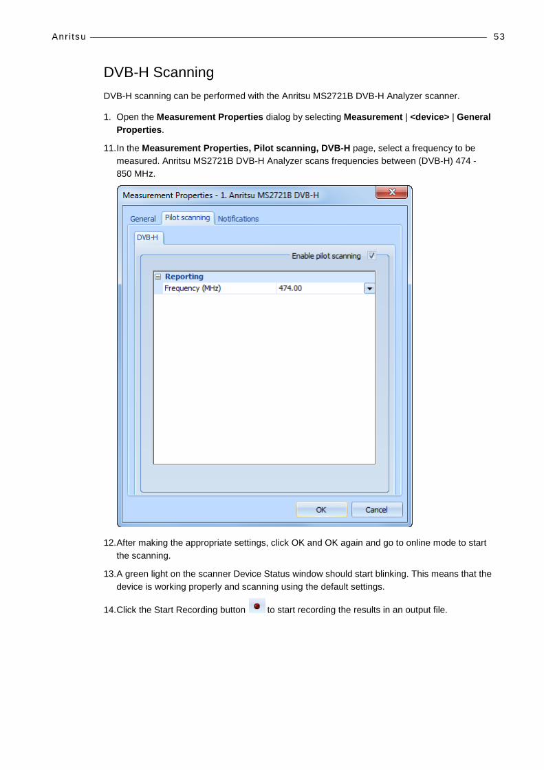
DVB-H Scanning DVB-H scanning can be performed with the Anritsu MS2721B DVB-H Analyzer scanner.
1. Open the Measurement Properties dialog by selecting Measurement | <device> | General Properties.
11. In the Measurement Properties, Pilot scanning, DVB-H page, select a frequency to be measured. Anritsu MS2721B DVB-H Analyzer scans frequencies between (DVB-H) 474 - 850 MHz.
12. After making the appropriate settings, click OK and OK again and go to online mode to start the scanning.
13. A green light on the scanner Device Status window should start blinking. This means that the device is working properly and scanning using the default settings.
14. Click the Start Recording button to start recording the results in an output file.

Anr itsu 54
Spectrum Analyzer Measurements Spectrum scanning can be performed with the Anritsu MS2721B Spectrum Analyzer scanner.
1. Open the Measurement Properties dialog by selecting Measurement | <device> | General Properties.
2. In the Measurement Properties dialog, go to the Spectrum scanning page.
Anr itsu 55
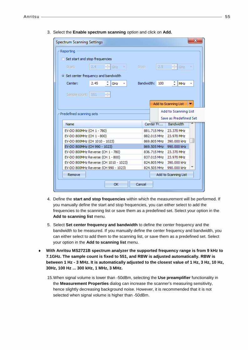
3. Select the Enable spectrum scanning option and click on Add.
4. Define the start and stop frequencies within which the measurement will be performed. If you manually define the start and stop frequencies, you can either select to add the frequencies to the scanning list or save them as a predefined set. Select your option in the Add to scanning list menu.
5. Select Set center frequency and bandwidth to define the center frequency and the bandwidth to be measured. If you manually define the center frequency and bandwidth, you can either select to add them to the scanning list, or save them as a predefined set. Select your option in the Add to scanning list menu.
♦ With Anritsu MS2721B spectrum analyzer the supported frequency range is from 9 kHz to 7.1GHz. The sample count is fixed to 551, and RBW is adjusted automatically. RBW is between 1 Hz - 3 MHz. It is automatically adjusted to the closest value of 1 Hz, 3 Hz, 10 Hz, 30Hz, 100 Hz ... 300 kHz, 1 MHz, 3 MHz.
15. When signal volume is lower than -50dBm, selecting the Use preamplifier functionality in the Measurement Properties dialog can increase the scanner’s measuring sensitivity, hence slightly decreasing background noise. However, it is recommended that it is not selected when signal volume is higher than -50dBm.

Anr itsu 56
16. You can add scanning sets in the Predefined scanning sets field through the Add to Scanning List button. Click the arrow in the button and select Save as Predefined Set. Define a name in the Enter Frequency Set Name field and click OK.
17. The name appears in the Predefined scanning sets field along with the chosen frequency and/or bandwidth information selected in the Reporting field.
18. After making the appropriate settings, click OK and OK again and go to online mode to start the scanning.
19. A green light on the scanner Device Status window should start blinking. This means that the device is working properly and scanning using the default settings.
20. Click the Start Recording button to start recording the results in an output file.

DRT 57
DRT
CONNECTING THE DRT WIMAX 4301A+ SCANNER
♦ Note! The DRT 4301A+ scanner does NOT have an On/OFF switch. The unit is powered by connecting the power cable and powered off by disconnecting the power cable. When connecting cables to the unit, the power cable should be the last one connected and the first one disconnected.
1. Insert one end of the RJ-45 cable in the DATA jack in the scanner, and connect the other end with the PC.
2. Insert the power cable in the connector marked DC IN.
3. Plug the antenna cable in the FR IN B port in your DRT scanner.
♦ Note that you can only select one of the antennas, 2300/2500MHz or the 3500MHz antenna, and connect it with the scanner. You must select between the antennas at this point.
4. Connect the scanner’s GPS antenna cable to the scanner’s GPS port, and place the GPS antenna on a visible spot.
5. Go to Start | Control Panel | Network Connections on your PC.
6. Right-click on Local Area Connection and select Properties.
7. In the Local Area Connection Properties dialog, select Internet Protocol (TCP/IP) | Properties.

DRT 58
8. In the General tab, select Use the following IP address, and type 192.168.5.1 in the IP address field, and 255.255.255.0 in the Subnet mask field.
9. Click OK and Close to exit the dialogs.
10. Now connect the scanner’s power cable. The scanner is now on. A green light will turn on in the scanner.
11. Start Nemo Outdoor. Go to Measurement | Add New Device | Scanner. Select DRT WIMAX 2300, DRT WIMAX 2500 or DRT WIMAX 3500 depending on which band you choose to measure at the time.

DRT 59
12. In the Scanner Properties dialog, select DRT LAN in the Port drop-down menu.
♦ Note that the Baud rate, Antenna gain and Cable loss fields do not affect the scanner, so they can be left as they are.
13. Click OK to exit the dialog.
14. Go to page 62 for more information on conducting WIMAX measurements with the DRT scanner.

DRT 60
STARTING DRT SCANNERS 1. Start Nemo Outdoor. Do not load any previous device configuration if asked.
2. From the Measurement menu, select Add New Device.
3. Click on Scanner.
4. From the list select:
• DRT WIMAX 2300, if you want to make measurements with the 2300 MHz (WiMAX) band.
• DRT WIMAX 2500, if you want to make measurements with the 2500MHz (WiMAX) band.
• DRT WIMAX 3500, if you want to make measurements with the 3500MHz (WiMAX) band.
DRT 61
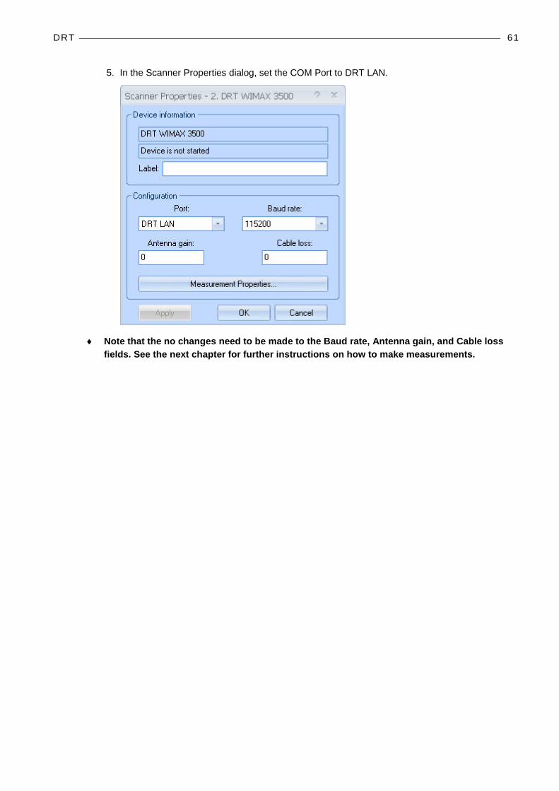
5. In the Scanner Properties dialog, set the COM Port to DRT LAN.
♦ Note that the no changes need to be made to the Baud rate, Antenna gain, and Cable loss fields. See the next chapter for further instructions on how to make measurements.
DRT 62
MEASURING WITH DRT SCANNERS
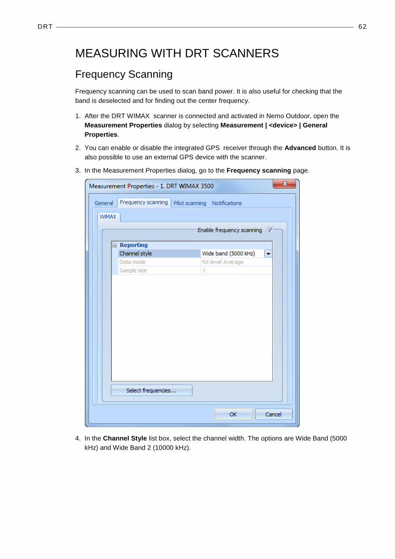
Frequency Scanning Frequency scanning can be used to scan band power. It is also useful for checking that the band is deselected and for finding out the center frequency.
1. After the DRT WIMAX scanner is connected and activated in Nemo Outdoor, open the Measurement Properties dialog by selecting Measurement | <device> | General Properties.
2. You can enable or disable the integrated GPS receiver through the Advanced button. It is also possible to use an external GPS device with the scanner.
3. In the Measurement Properties dialog, go to the Frequency scanning page.
4. In the Channel Style list box, select the channel width. The options are Wide Band (5000 kHz) and Wide Band 2 (10000 kHz).

DRT 63
5. Click the Select Frequencies button to open the Select Frequencies dialog.
6. The table displays the available frequencies. Select and add them in the Selected view by clicking on Add>>.
7. Remove frequencies from the Selected list by selecting a frequency and clicking the Remove button.
8. Add frequencies in the Selected list by selecting a frequency from the Available list and clicking the Add button.
9. Click OK to return to the Measurement Properties dialog.
10. After making the appropriate settings, click OK and OK again and go to online mode to start the scanning.
11. A green light on the scanner Device Status window should start blinking. This means that the device is working properly and scanning using the default settings. In TOP-N Mode this may take a few seconds.
12. Click the Start Recording button to start recording the results in an output file.

DRT 64
Pilot Scanning 1. After the DRT WIMAX scanner is connected and activated in Nemo Outdoor, open the
Measurement Properties dialog by selecting Measurement | <device> | General Properties.
2. In the Measurement Properties dialog, go to the Pilot scanning page.
Channel style refers to the style of the channel.
Data processing method defines how the scanned data is processed by the scanner. In aggregate method, the sum of all peak pilot Ec/Io values above the PN threshold is calculated.
Top-N option enables/disables TOP-N scrambling code scanning. If enabled, scanner will report results from N best preambles. Number of preambles field defines how many preambles are reported by the scanner in TOP-N mode.
CINR refers to the Carrier to Interference and Noise ratio value, in dB *100 (e.g., -16.34). It is based on the requested reuse factor.
Preamble delay refers to the number of samples between expected arrival time and actual arrival time of preamble with respect to GPS time reference. The values range from 0 to 1023+32. Each sample corresponds to 89.285 nanoseconds.

DRT 65
Reuse factor refers to a system design parameter that can be manipulated to achieve the desired balance between the interference and the network coverage. The WiMAX air interface modulating waveform has been divided into three segments (Segment 0, 1 and 2). The allocation of frequency sub-carrier into these three segments is done in such a way that e.g. a downlink signal on segment 0 will not interfere with the downlink signal on segment 1. In a Reuse Factor 1 measurement, contributions from all the three segments are considered in the measured parameters, so that the CINRs are calculated from all the three segments. When Reuse Factor 3 is selected, only the contribution of the desired segment is considered, and the CINRs are calculated only from the same segment. As a broad guideline, measurements performed with Reuse Factor 1 will provide the signal quality of the all the detected preambles relative to each other, whereas the Reuse Factor 3 category of measurements will provide the signal quality of preambles within the same segment.
Delay spread defines if the selected scanner will also measure the delay spread value (in chips) for each scanned scrambling code. Delay spread is determined as the difference between the last and first component to break the threshold set in PN Threshold.
3. The Top-N Configuration button will open the Select Frequencies dialog where you can select frequencies for scanning. The maximum number of frequencies that can be selected is device specific.

DRT 66
4. After making the appropriate settings, click OK and OK again and go to online mode to start the scanning.
5. A green light on the scanner Device Status window should start blinking. This means that the device is working properly and scanning using the default settings. In TOP-N Mode this may take a few seconds.
6. Click the Start Recording button to start recording the results in an output file.
PCTEL 67
PCTEL
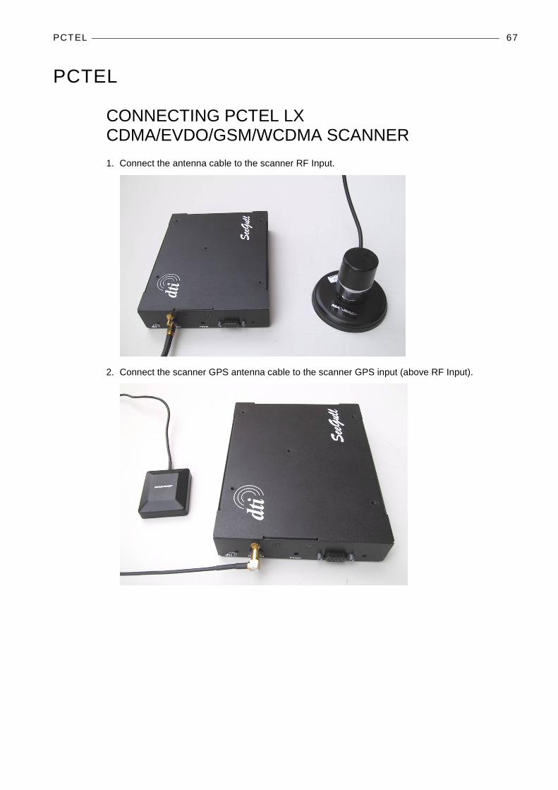
CONNECTING PCTEL LX CDMA/EVDO/GSM/WCDMA SCANNER 1. Connect the antenna cable to the scanner RF Input.
2. Connect the scanner GPS antenna cable to the scanner GPS input (above RF Input).
PCTEL 68
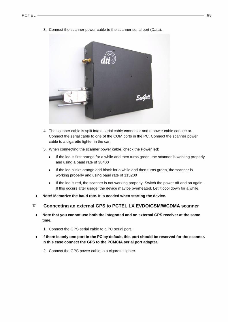
3. Connect the scanner power cable to the scanner serial port (Data).
4. The scanner cable is split into a serial cable connector and a power cable connector. Connect the serial cable to one of the COM ports in the PC. Connect the scanner power cable to a cigarette lighter in the car.
5. When connecting the scanner power cable, check the Power led:
• If the led is first orange for a while and then turns green, the scanner is working properly and using a baud rate of 38400
• If the led blinks orange and black for a while and then turns green, the scanner is working properly and using baud rate of 115200
• If the led is red, the scanner is not working properly. Switch the power off and on again. If this occurs after usage, the device may be overheated. Let it cool down for a while.
♦ Note! Memorize the baud rate. It is needed when starting the device.
∇ Connecting an external GPS to PCTEL LX EVDO/GSM/WCDMA scanner
♦ Note that you cannot use both the integrated and an external GPS receiver at the same time.
1. Connect the GPS serial cable to a PC serial port.
♦ If there is only one port in the PC by default, this port should be reserved for the scanner. In this case connect the GPS to the PCMCIA serial port adapter.
2. Connect the GPS power cable to a cigarette lighter.
PCTEL 69
CONNECTING PCTEL EX SCANNERS 1. To install the device drivers the user must have administrative rights to its PC, and the Take
ownership of files or other objects policy has to be enabled for this user on this PC.
2. Copy the folder /SeeGull EX VCP driver_v.2.0.0.46B to your local drive before installing the driver, and run the installation from the hard drive.
• Right click on the folder and select Properties.
• Clear the Read-only attributes and click OK.
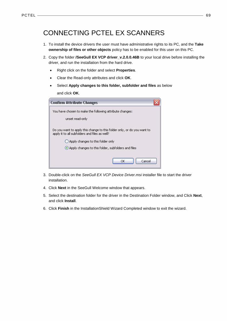
• Select Apply changes to this folder, subfolder and files as below
and click OK.
3. Double-click on the SeeGull EX VCP Device Driver.msi installer file to start the driver installation.
4. Click Next in the SeeGull Welcome window that appears.
5. Select the destination folder for the driver in the Destination Folder window, and Click Next, and click Install.
6. Click Finish in the InstallationShield Wizard Completed window to exit the wizard.
PCTEL 70
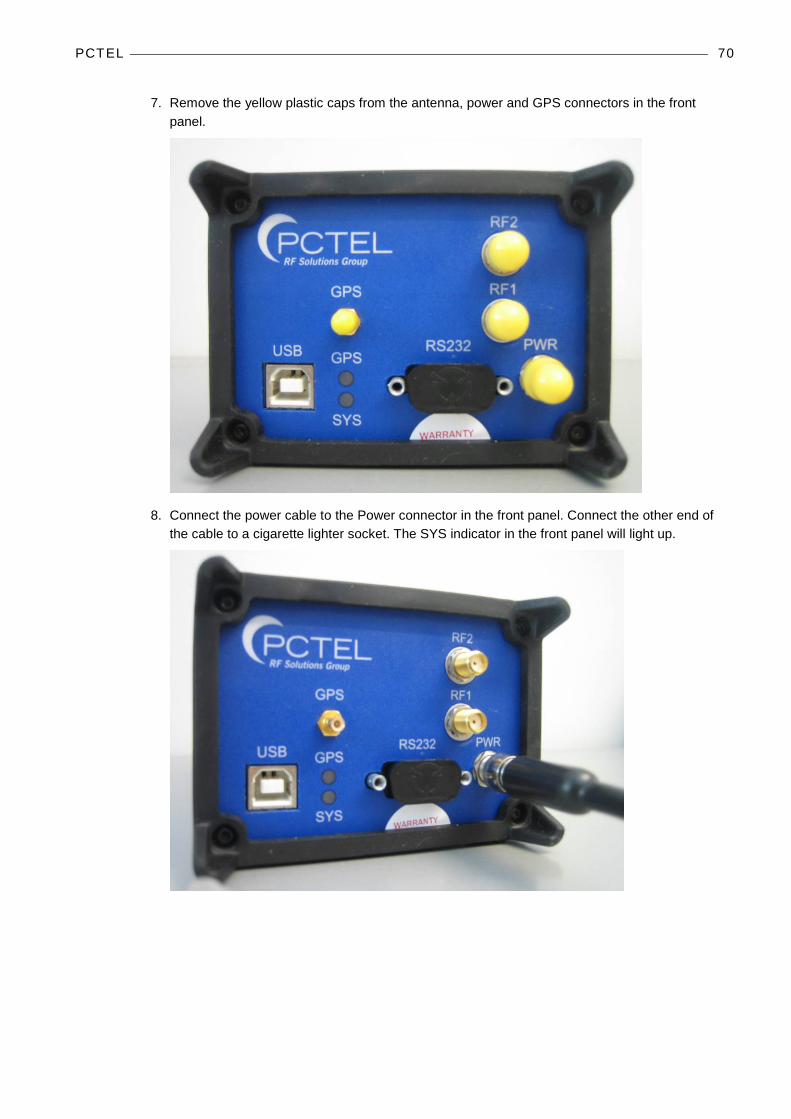
7. Remove the yellow plastic caps from the antenna, power and GPS connectors in the front panel.
8. Connect the power cable to the Power connector in the front panel. Connect the other end of the cable to a cigarette lighter socket. The SYS indicator in the front panel will light up.

PCTEL 71
9. Connect the antenna cables. It does not matter which antenna cable goes to which RF connector.
10. Connect the GPS antenna to the connector marked GPS.
PCTEL 72
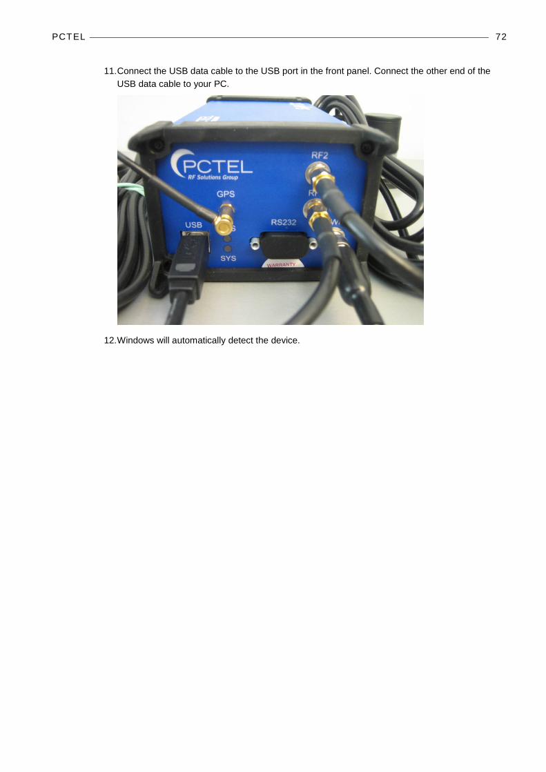
11. Connect the USB data cable to the USB port in the front panel. Connect the other end of the USB data cable to your PC.
12. Windows will automatically detect the device.
PCTEL 73
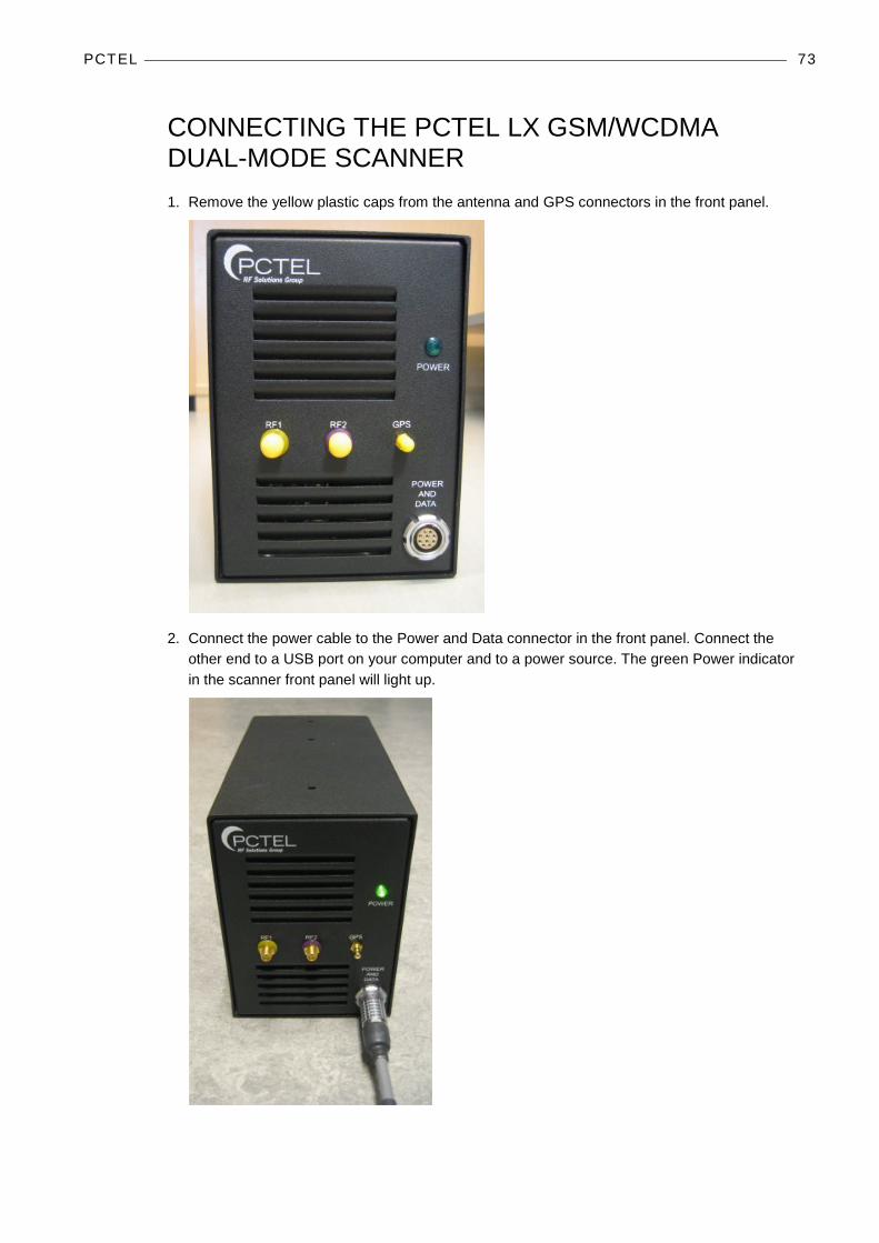
CONNECTING THE PCTEL LX GSM/WCDMA DUAL-MODE SCANNER 1. Remove the yellow plastic caps from the antenna and GPS connectors in the front panel.
2. Connect the power cable to the Power and Data connector in the front panel. Connect the other end to a USB port on your computer and to a power source. The green Power indicator in the scanner front panel will light up.

PCTEL 74
3. Connect the antenna cables. Note that the antenna cables and the connectors in the scanner front panel are color coded. The OP042 cable marked with yellow is connected to the RF1 connector marked with yellow (connector on the left). The OP039 cable marked with blue is connected to the RF2 connector marked with purple (connector in the middle).
4. Connect the GPS antenna to the connector marked GPS (connector on the right).
5. Windows will have detected the new device and will install the required drivers. Insert the PCTEL installation CD.
6. Select No, not this time in the Welcome dialog.

PCTEL 75
7. Select Install from a list of specific location and click Next.
8. Select Include this option in the search and browse to folder D:\EdgeportUSB\Edgeport Vendor Data\driver vx.x. Click Next to start the installation.
9. When the installation is finished, click Finish. Windows will automatically install some additional drivers and report when the device is ready to be used.
PCTEL 76
CONNECTING THE PCTEL MX SCANNER 1. To install the device drivers the user must have administrative rights to its PC, and the Take
ownership of files or other objects policy has to be enabled for this user on this PC.
2. Browse to folder seegull mx driver\MX winusb driver. For 32-bit operating system run DPInst.exe from “install x86” folder and for 64-bit operating system run DPInst.exe from “install x64” folder.
3. The PCTEL USB Device Installer window will appear. Click Next.
4. If a Windows Security message appears, click Install.
5. Click Finish in the installation completed window.
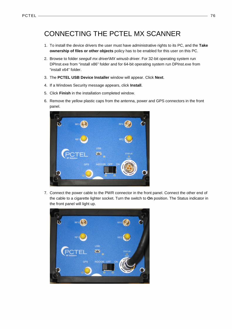
6. Remove the yellow plastic caps from the antenna, power and GPS connectors in the front panel.
7. Connect the power cable to the PWR connector in the front panel. Connect the other end of the cable to a cigarette lighter socket. Turn the switch to On position. The Status indicator in the front panel will light up.
PCTEL 77
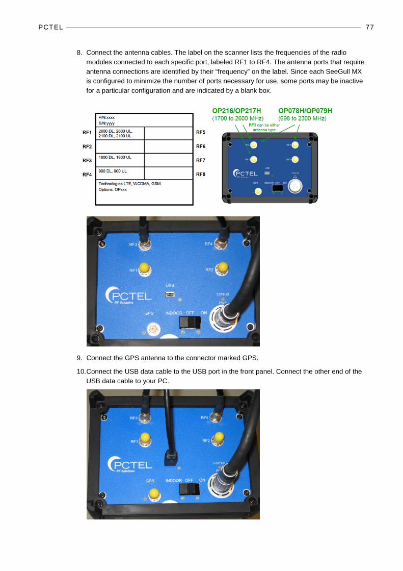
8. Connect the antenna cables. The label on the scanner lists the frequencies of the radio modules connected to each specific port, labeled RF1 to RF4. The antenna ports that require antenna connections are identified by their “frequency” on the label. Since each SeeGull MX is configured to minimize the number of ports necessary for use, some ports may be inactive for a particular configuration and are indicated by a blank box.
9. Connect the GPS antenna to the connector marked GPS.
10. Connect the USB data cable to the USB port in the front panel. Connect the other end of the USB data cable to your PC.

PCTEL 78
11. Windows Vista and Windows 7 will automatically detect and install the device.
12. With Windows XP a Found new Hardware window will appear. Select No, not this time in the Welcome window. Select Install the software automatically (Recommended) and click Next. Finally click Finish.
13. Go to Device Manager and select PCTEL Devices. Memorize the port number for the PCTEL MX Scanner item, as you will need it later on.

PCTEL 79
CONNECTING PCTEL PCT SCANNERS 1. Run the PL2303_Prolific_DriverInstaller_vx.x.exe (x refers to the version number) file on the
installation CD to install device drivers.
2. Click Next in the Welcome window that appears.
3. Click Finish to finish the driver installation.
4. Next, remove the yellow plastic caps from the antenna and GPS connectors in the front panel of the PCTEL PCT scanner.
5. Connect the antenna cable in the RF Input connector.

PCTEL 80
6. Connect the data cable to the Data connector. Connect the other end of the USB data cable to your PC.
7. Connect the power cable to the Power connector in the front panel. Connect the other end of the cable to a cigarette lighter socket.
8. Windows automatically detects the new hardware.

PCTEL 81
9. Go to Start | Control Panel | System | Hardware | Device Manager and select Ports. Memorize the port number for the Prolific USB-to-Serial Comm Port item, as you will need it later on.

PCTEL 82
CONNECTING PCTEL SCANNERS TO NEMO INVEX CHASSIS PCTEL scanners are connected to the Nemo Invex chassis (UIC module) with a USB cable. If your PCTEL scanner has a serial cable, you will need a USB serial adapter. The USB cable is connected to the USB-1 or USB-2 port on the UIC module.
PCTEL scanners can be attached on top of the Nemo Invex chassis with a mounting plate.
PCTEL 83
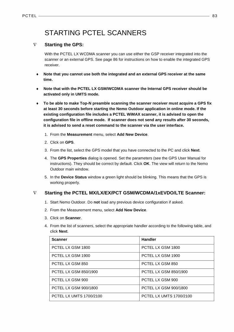
STARTING PCTEL SCANNERS ∇ Starting the GPS:
With the PCTEL LX WCDMA scanner you can use either the GSP receiver integrated into the scanner or an external GPS. See page 86 for instructions on how to enable the integrated GPS receiver.
♦ Note that you cannot use both the integrated and an external GPS receiver at the same time.
♦ Note that with the PCTEL LX GSM/WCDMA scanner the Internal GPS receiver should be activated only in UMTS mode.
♦ To be able to make Top-N preamble scanning the scanner receiver must acquire a GPS fix at least 30 seconds before starting the Nemo Outdoor application in online mode. If the existing configuration file includes a PCTEL WiMAX scanner, it is advised to open the configuration file in offline mode. If scanner does not send any results after 30 seconds, it is advised to send a reset command to the scanner via the user interface.
1. From the Measurement menu, select Add New Device.
2. Click on GPS.
3. From the list, select the GPS model that you have connected to the PC and click Next.
4. The GPS Properties dialog is opened. Set the parameters (see the GPS User Manual for instructions). They should be correct by default. Click OK. The view will return to the Nemo Outdoor main window.
5. In the Device Status window a green light should be blinking. This means that the GPS is working properly.
∇ Starting the PCTEL MX/LX/EX/PCT GSM/WCDMA/1xEVDO/LTE Scanner:
1. Start Nemo Outdoor. Do not load any previous device configuration if asked.
2. From the Measurement menu, select Add New Device.
3. Click on Scanner.
4. From the list of scanners, select the appropriate handler according to the following table, and click Next.
Scanner Handler
PCTEL LX GSM 1800 PCTEL LX GSM 1800
PCTEL LX GSM 1900 PCTEL LX GSM 1900
PCTEL LX GSM 850 PCTEL LX GSM 850
PCTEL LX GSM 850/1900 PCTEL LX GSM 850/1900
PCTEL LX GSM 900 PCTEL LX GSM 900
PCTEL LX GSM 900/1800 PCTEL LX GSM 900/1800
PCTEL LX UMTS 1700/2100 PCTEL LX UMTS 1700/2100

PCTEL 84
PCTEL LX UMTS 1900 PCTEL LX UMTS 1900
PCTEL LX UMTS 2100 PCTEL LX UMTS 2100
PCTEL LX UMTS 850/1900 PCTEL LX UMTS 850/1900
PCTEL LX UMTS 850 PCTEL LX UMTS 850
PCTEL LX CDMA/EVDO 850 PCTEL LX EVDO 800
PCTEL LX 1xEVDO 450 PCTEL LX EVDO 450
PCTEL LX 1xEVDO 850 PCTEL LX EVDO 800
PCTEL LX 1xEVDO 1900 PCTEL LX EDVO 1900
PCTEL LX 1xEVDO 800/1900 PCTEL LX EDVO 800/1900
PCTEL EX CDMA/EVDO 850/1900 PCTEL EX CDMA2000 850/1900 EVDO 850/1900
PCTEL EX GSM 850/1900 & WCDMA 850/1900 PCTEL EX GSM 850/1900 UMTS 850/1900
PCTEL EX GSM 900/1800 & WCDMA 900/2100 PCTEL EX GSM 900/1800 UMTS 900/2100
PCTEL EX GSM 900/1800 & WCDMA 2100 PCTEL EX GSM 900/1800 UMTS 2100
PCTEL EX GSM 1900 & WCDMA 2100 AWS PCTEL EX GSM 1900 UMTS AWS
PCTEL EX WIMAX PCTEL EX WIMAX
PCTEL EX 900/1800 WCDMA/TD-SCDMA 2000 PCTEL EX 900/1800 UMTS TDSCDMA 2000
PCTEL EX WCDMA 2100 AWS&GSM 850/ 1900 PCTEL EX GSM 850/1900 UMTS AWS
PCTEL EX LTE 700ABC PCTEL EX LTE 700ABC
PCTEL EX LTE 700ABC/Upper 700C/AWS PCTEL EX LTE 700ABC/Upper 700C/AWS
PCTEL EX LTE 700C PCTEL EX LTE 700C
PCTEL EX LTE AWS/700BC PCTEL EX LTE AWS/700BC
PCTEL EX LTE AWS/700C PCTEL EX LTE AWS/700C
PCTEL EX LTE 800 PCTEL EX LTE 800
PCTEL EX LTE 800/2600 PCTEL EX LTE 800/2600
PCTEL EX LTE 1600 PCTEL EX LTE 1600
PCTEL EX LTE 1800/2600 PCTEL EX LTE 1800/2600
PCTEL EX LTE 2100 PCTEL EX LTE 2100
PCTEL EX LTE 2100/2600 PCTEL EX LTE 2100/2600
PCTEL EX LTE 2600 PCTEL EX LTE 2600
PCTEL EX LTE AWS PCTEL EX LTE AWS

PCTEL 85
PCTEL EX Mini series scanners:
• WCDMA 2100 PCTEL EX UMTS 2100
• WCDMA 850/1900 PCTEL EX UMTS 850/1900
• WCDMA 900/2100 PCTEL EX UMTS 900/2100
• WCDMA AWS PCTEL EX UMTS AWS
PCTEL MX PCTEL MX
PCTEL PCT GSM 900/1800 PCTEL PCT GSM 900/1800
PCTEL PCT UMTS 2100 PCTEL PCT UMTS 2100
5. In the Scanner Properties dialog, set the COM Port to the port the scanner is connected to. With MX scanners, select the PCTEL USB item.
6. Set the baud rate to the one used by the scanner and click OK. The dialog will be closed and the scanner should now be connected to the system.
7. If the dialog did not close, the start-up did not succeed. Check the cable connections and the settings and try again.
8. From the View menu activate Device Status. A check mark will appear next to the command when it is activated.
9. A green light on the PCTEL scanner in the Device Status window should be blinking. This means that the device is working properly and scanning using the default settings. See chapter Starting Measurement (page 125) for instructions on making your own scanner configuration.
PCTEL 86
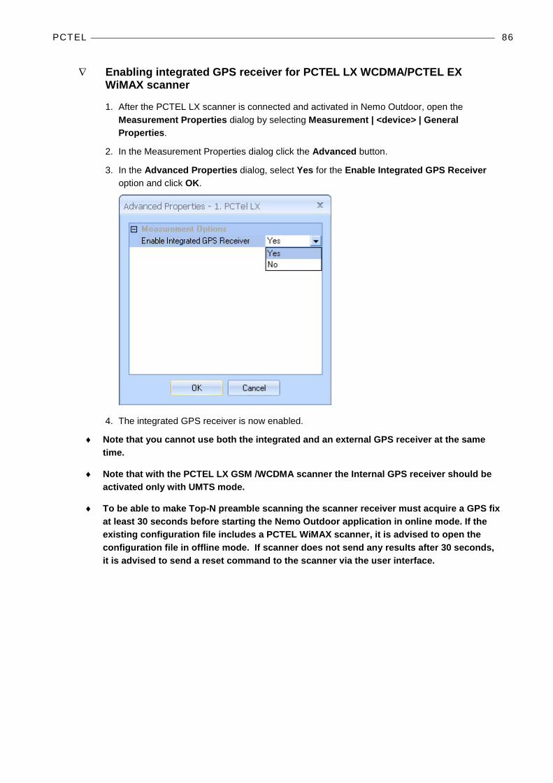
∇ Enabling integrated GPS receiver for PCTEL LX WCDMA/PCTEL EX WiMAX scanner
1. After the PCTEL LX scanner is connected and activated in Nemo Outdoor, open the Measurement Properties dialog by selecting Measurement | <device> | General Properties.
2. In the Measurement Properties dialog click the Advanced button.
3. In the Advanced Properties dialog, select Yes for the Enable Integrated GPS Receiver option and click OK.
4. The integrated GPS receiver is now enabled.
♦ Note that you cannot use both the integrated and an external GPS receiver at the same time.
♦ Note that with the PCTEL LX GSM /WCDMA scanner the Internal GPS receiver should be activated only with UMTS mode.
♦ To be able to make Top-N preamble scanning the scanner receiver must acquire a GPS fix at least 30 seconds before starting the Nemo Outdoor application in online mode. If the existing configuration file includes a PCTEL WiMAX scanner, it is advised to open the configuration file in offline mode. If scanner does not send any results after 30 seconds, it is advised to send a reset command to the scanner via the user interface.

PCTEL 87
∇ Starting the PCTEL LX GSM/WCDMA dual-mode scanner
1. Start Nemo Outdoor. Do not load any previous device configuration if asked.
2. From the Measurement menu, select Add New Device.
3. Click on Scanner.
4. From the list select PCTEL LX GSM 900/1800 and click Next.
5. In the Scanner Properties dialog, Port field you should see two consecutive COM ports (e.g., COM 3 and COM 4). Select the COM port with the smaller number and click OK.
6. From the Measurement menu, select Add New Device. Click on Scanner.
7. From the list select PCTEL LX UMTS 2100 and click Next.
8. In the Scanner Properties dialog, Port field you should see two consecutive COM ports (e.g., COM 3 and COM 4). Select the COM port with the bigger number and click OK.
9. A green light should be blinking in the Device Status for both devices. This means that the devices are working properly and scanning using the default settings. If the status field displays, Device is not started, check that you are in online mode (click the Work Offline/Online button ).
10. The GSM and UMTS scanners will appear as separate devices and must be configured individually.
PCTEL 88
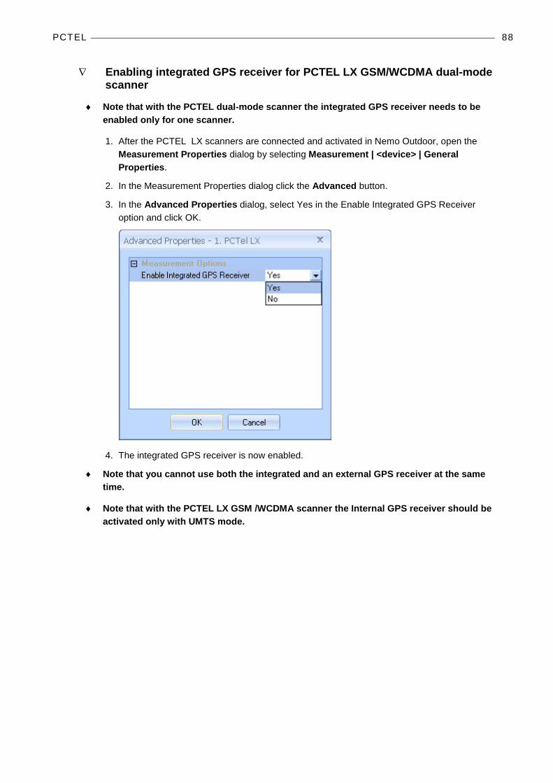
∇ Enabling integrated GPS receiver for PCTEL LX GSM/WCDMA dual-mode scanner
♦ Note that with the PCTEL dual-mode scanner the integrated GPS receiver needs to be enabled only for one scanner.
1. After the PCTEL LX scanners are connected and activated in Nemo Outdoor, open the Measurement Properties dialog by selecting Measurement | <device> | General Properties.
2. In the Measurement Properties dialog click the Advanced button.
3. In the Advanced Properties dialog, select Yes in the Enable Integrated GPS Receiver option and click OK.
4. The integrated GPS receiver is now enabled.
♦ Note that you cannot use both the integrated and an external GPS receiver at the same time.
♦ Note that with the PCTEL LX GSM /WCDMA scanner the Internal GPS receiver should be activated only with UMTS mode.

PCTEL 89
MEASURING WITH PCTEL SCANNERS
Frequency Scanning – PCTEL GSM/UMTS Scanners Frequency scanning can be used to scan band power. It is also useful for checking that the band is deselected and for finding out the center frequency.
1. After the scanner is connected and activated in Nemo Outdoor, open the Measurement Properties dialog by selecting Measurement | <device> | General Properties.
2. In the Measurement Properties dialog, go to the Frequency scanning, UMTS page.
3. In the Channel style field, select the channel width. The options are narrow band (200 kHz) and wide band (3.84 MHz).
♦ To find out the center frequency used, set the Channel Style to 200 kHz and select all the channels in the frequency region where the carrier should exist; for example, all channels allocated to an operator. The center frequency will stand out in Frequency Scanning mode. The received signal should be above the noise level in order to find out the center frequency.
PCTEL 90
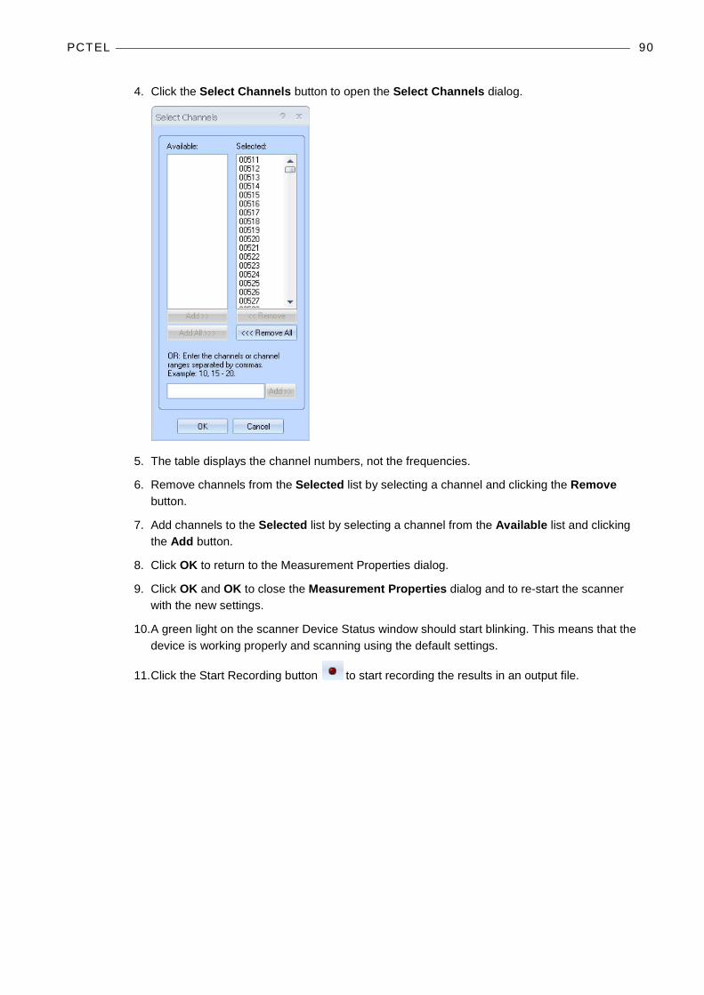
4. Click the Select Channels button to open the Select Channels dialog.
5. The table displays the channel numbers, not the frequencies.
6. Remove channels from the Selected list by selecting a channel and clicking the Remove button.
7. Add channels to the Selected list by selecting a channel from the Available list and clicking the Add button.
8. Click OK to return to the Measurement Properties dialog.
9. Click OK and OK to close the Measurement Properties dialog and to re-start the scanner with the new settings.
10. A green light on the scanner Device Status window should start blinking. This means that the device is working properly and scanning using the default settings.
11. Click the Start Recording button to start recording the results in an output file.

PCTEL 91
Frequency Scanning – PCTEL EX LTE Scanner 1. After the scanner is connected and activated in Nemo Outdoor, open the Measurement
Properties dialog by selecting Measurement | <device> | General Properties. By clicking the Advanced button on the General page, you will access the Advanced Properties dialog. Here you can enable and disable the integrated GPS receiver. This means you will not need an external GPS receiver in order to collect position data.
2. On the Frequency scanning page, define the Channel style.
PCTEL 92
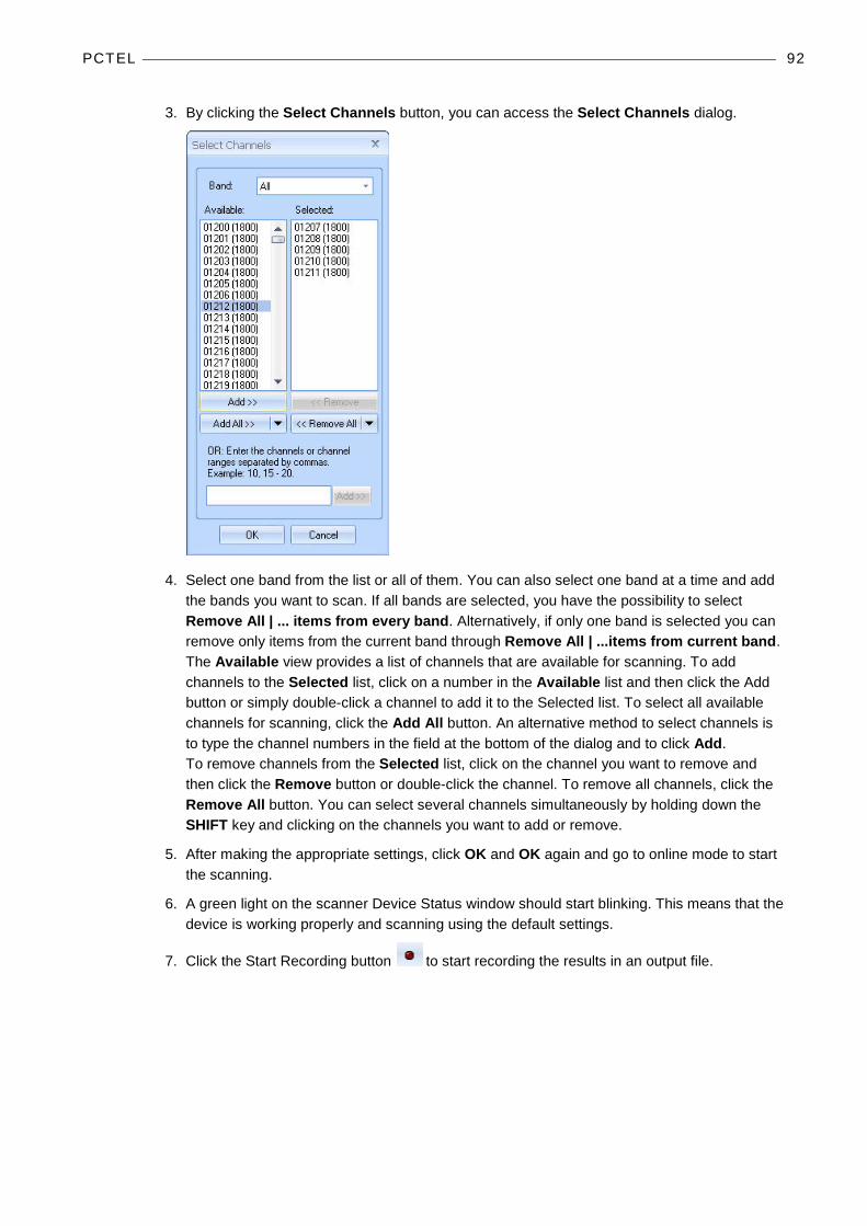
3. By clicking the Select Channels button, you can access the Select Channels dialog.
4. Select one band from the list or all of them. You can also select one band at a time and add the bands you want to scan. If all bands are selected, you have the possibility to select Remove All | ... items from every band. Alternatively, if only one band is selected you can remove only items from the current band through Remove All | ...items from current band. The Available view provides a list of channels that are available for scanning. To add channels to the Selected list, click on a number in the Available list and then click the Add button or simply double-click a channel to add it to the Selected list. To select all available channels for scanning, click the Add All button. An alternative method to select channels is to type the channel numbers in the field at the bottom of the dialog and to click Add. To remove channels from the Selected list, click on the channel you want to remove and then click the Remove button or double-click the channel. To remove all channels, click the Remove All button. You can select several channels simultaneously by holding down the SHIFT key and clicking on the channels you want to add or remove.
5. After making the appropriate settings, click OK and OK again and go to online mode to start the scanning.
6. A green light on the scanner Device Status window should start blinking. This means that the device is working properly and scanning using the default settings.
7. Click the Start Recording button to start recording the results in an output file.

PCTEL 93
Frequency Scanning – PCT GSM Scanner 1. After the scanner is connected and activated in Nemo Outdoor, open the Measurement
Properties dialog by selecting Measurement | <device> | General Properties.
2. By clicking the Advanced button, you will access the Advanced Properties dialog. Here you can enable and disable the integrated GPS receiver. This means you will not need an external GPS receiver in order to collect position data.
3. Go to the Frequency scanning page.
Channel style refers to the style of the channel.
Selecting the BSIC decoding option displays BSIC value in a measurement window.
BSIC threshold defines the minimum BSIC level that the scanner reports.
Select the BCCH C/I option to activate C/I measurements for the BCCH channel. This option is available with PCTEL GSM scanners only.

PCTEL 94
4. By clicking the Select Channels button, you can access the Select Channels dialog.
5. Select one band from the list or all of them. You can also select one band at a time and add the bands you want to scan. If all bands are selected, you have the possibility to select Remove All | ... items from every band. Alternatively, if only one band is selected you can remove only items from the current band through Remove All | ...items from current band.
The Available view provides a list of channels that are available for scanning. To add channels to the Selected list, click on a number in the Available list and then click the Add button or simply double-click a channel to add it to the Selected list. To select all available channels for scanning, click the Add All button. An alternative method to select channels is to type the channel numbers in the field at the bottom of the dialog and to click Add.
To remove channels from the Selected list, click on the channel you want to remove and then click the Remove button or double-click the channel. To remove all channels, click the Remove All button. You can select several channels simultaneously by holding down the SHIFT key and clicking on the channels you want to add or remove.
♦ Note that Sample size and Data mode are not enabled with PCT GSM frequency scanning

PCTEL 95
6. After making the appropriate settings, click OK and OK again and go to online mode to start the scanning.
7. A green light on the scanner Device Status window should start blinking. This means that the device is working properly and scanning using the default settings.
8. Click the Start Recording button to start recording the results in an output file.
Frequency Scanning – PCTEL CDMA/EVDO Scanners 1. After the scanner is connected and activated in Nemo Outdoor, open the Measurement
Properties dialog by selecting Measurement | <device> | General Properties.
2. By clicking the Advanced button, you will access the Advanced Properties dialog. Here you can enable and disable the integrated GPS receiver. This means you will not need an external GPS receiver in order to collect position data.
3. Go to the Frequency scanning page.
Channel style refers to the style of the channel. For EVDO scanners, the options are 1250 kHz Normal and 30 kHz Normal.
Sample size defines the number of samples taken from each channel before a measurement result is written to file.

PCTEL 96
4. By clicking the Select Channels button, you can access the Select Channels dialog.
5. Select one band from the list or all of them. You can also select one band at a time and add the bands you want to scan. If all bands are selected, you have the possibility to select Remove All | ... items from every band. Alternatively, if only one band is selected you can remove only items from the current band through Remove All | ...items from current band.
The Available view provides a list of channels that are available for scanning. To add channels to the Selected list, click on a number in the Available list and then click the Add button or simply double-click a channel to add it to the Selected list. To select all available channels for scanning, click the Add All button. An alternative method to select channels is to type the channel numbers in the field at the bottom of the dialog and to click Add. To remove channels from the Selected list, click on the channel you want to remove and then click the Remove button or double-click the channel. To remove all channels, click the Remove All button. You can select several channels simultaneously by holding down the SHIFT key and clicking on the channels you want to add or remove.
6. After making the appropriate settings, click OK and OK again and go to online mode to start the scanning.
7. A green light on the scanner Device Status window should start blinking. This means that the device is working properly and scanning using the default settings.
8. Click the Start Recording button to start recording the results in an output file.
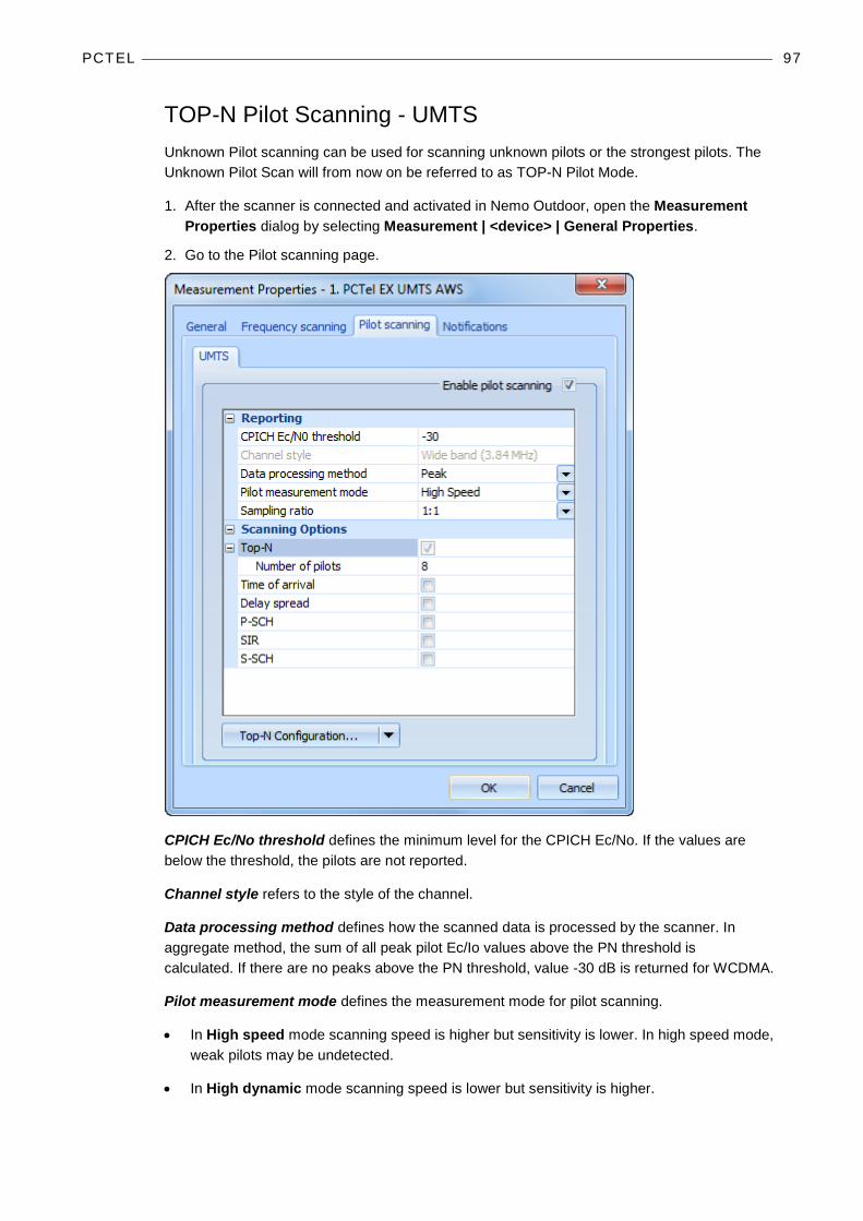
PCTEL 97
TOP-N Pilot Scanning - UMTS Unknown Pilot scanning can be used for scanning unknown pilots or the strongest pilots. The Unknown Pilot Scan will from now on be referred to as TOP-N Pilot Mode.
1. After the scanner is connected and activated in Nemo Outdoor, open the Measurement Properties dialog by selecting Measurement | <device> | General Properties.
2. Go to the Pilot scanning page.
CPICH Ec/No threshold defines the minimum level for the CPICH Ec/No. If the values are below the threshold, the pilots are not reported.
Channel style refers to the style of the channel.
Data processing method defines how the scanned data is processed by the scanner. In aggregate method, the sum of all peak pilot Ec/Io values above the PN threshold is calculated. If there are no peaks above the PN threshold, value -30 dB is returned for WCDMA.
Pilot measurement mode defines the measurement mode for pilot scanning.
• In High speed mode scanning speed is higher but sensitivity is lower. In high speed mode, weak pilots may be undetected.
• In High dynamic mode scanning speed is lower but sensitivity is higher.
PCTEL 98
Top-N option enables/disables Top-N scrambling code scanning. If enabled, scanner will report results from N best scrambling codes. Number of pilots field defines how many pilots are reported by scanner in Top-N mode.
Time of arrival defines if the selected scanner will measure the time of arrival for each scrambling code. The time of arrival value is relative to GPS time and is measured in chips.
Delay spread defines if the selected scanner will also measure the delay spread value (in chips) for each scanned scrambling code. Delay spread is determined as the difference between the last and first component to break the threshold set in PN Threshold.
P-SCH defines if the selected scanner will measure the P-SCH Ec/N0 value for each scrambling code.
SIR (signal to interference ratio) defines if the selected scanner will measure the SIR value for each scrambling code.
S-SCH defines if the selected scanner will measure the S-SCH Ec/N0 value for each scrambling code.
∇ To select channels:
1. In the Measurement Properties, Pilot scanning, UMTS page, click the Top-N Configuration button. The Select Channels dialog is opened.
♦ The table displays the channel numbers, not the frequencies. If you know the frequency but not the channel number, the channel number can be calculated by multiplying the frequency in MHz by five. The channel spacing is always 200 kHz.
2. Remove channels from the Selected list by selecting a channel and clicking the Remove button.
3. Add channels to the Selected list by selecting a channel from the Available list and clicking the Add button.
♦ With a PCTEL LX scanner a maximum of 8 channels can be selected in the pilot mode.
♦ With a PCTEL EX scanner a maximum of 15 channels can be selected in the pilot mode.
♦ With a PCTEL MX scanner 1 channel can be selected in the pilot mode.
♦ With a PCTEL LTE EX scanner a maximum of 15 channels can be selected in the pilot mode.
♦ With a PCTEL PCT scanner a maximum of 4 channels can be selected in the pilot mode.
4. Click OK to return to the Measurement Properties dialog.
∇ To select pilot parameters:
1. Select the TOP-N Mode option.
2. Set the Number of scrambling codes value. This defines how many strongest pilots are to be reported by the scanner. The maximum is 32 pilots.
♦ Note that with the PCTEL PCT Scanner the maximum number of pilots to be selected for scanning is 8.
PCTEL 99
♦ Note that the PCTEL EX WCDMA scanner only supports the TOP-N mode. You can select up to 32 pilots for scanning.
3. To improve on the accuracy of radio propagation models, High speed mode makes it possible to acquire more samples (max 32 pilots per channel), while High dynamic mode offers fewer samples (max 16 pilots per channel) with a larger dynamic range.
∇ To set general parameters:
1. Data processing method defines how the scanner will process samples before reporting.
2. PN threshold defines the limit above which Ec/N0 peaks must go if Aggregated data processing method is used.
∇ To select measured values:
♦ In Pilot Scanning Mode the RSSI is always measured for each channel.
♦ In Pilot Scanning Mode the P-CPICH Ec/N0 and RSCP are always measured for each scrambling code.
1. In the Measurement Properties, Pilot scanning page:
• Select the P-SCH option to enable P-SCH Ec/N0 and RSCP measurement. • Select the S-SCH option to enable S-SCH Ec/N0 and RSCP measurement. • Select the Time of arrival option to enable time of arrival measurement. • Select the Delay spread option to enable P-CPICH delay spread measurement. • Select the SIR option to enable P-CPICH SIR measurement. • Select the Delay profile option to enable P-CPICH Delay Profile measurement. In TOP-
N pilot scanning mode the scrambling code for delay profile measurement cannot be selected.
2. After making the appropriate settings, click OK and OK again and go to online mode to start the scanning.
3. A green light on the scanner Device Status window should start blinking. This means that the device is working properly and scanning using the default settings.
4. Click the Start Recording button to start recording the results in an output file.
TOP-N Pilot Scanning – CDMA/EVDO Unknown Pilot scanning can be used for scanning unknown pilots or the strongest pilots. The Unknown Pilot Scan will from now on be referred to as TOP-N Pilot Mode.
1. After the PCTEL LX/EX scanner is connected and activated in Nemo Outdoor, open the Measurement Properties dialog by selecting Measurement | <device> | General Properties.
2. By clicking the Advanced button, you will access the Advanced Properties dialog. Here you can enable and disable the integrated GPS receiver. This means you will not need an external GPS receiver in order to collect position data.

PCTEL 100
3. In the Measurement Properties dialog, go to Pilot scanning page.
Channel style refers to the style of the channel.
Data processing method defines how the scanned data is processed by the scanner. In aggregate method, the sum of all peak pilot Ec/Io values above the PN threshold is calculated. If there are no peaks above the PN threshold, value -30 dB is returned for WCDMA.
Pilot window mode defines the position of the chips that are searched for pilot across in regard to the ideal pilot position (0 chip delay for a given pilot).
Sampling ratio option is available for PCTEL EX scanners only. The available options are 1:1, 1:2, 1:4 and 1:8. With ratio 1:1 all samples (Pilotscan events) are logged, with ratio 1:2 every second sample is logged, with ratio 1:4 every 4th sample is logged, and with ratio 1:8 every 8th sample is logged. By decreasing the sampling ratio you can decrease the output file size, but the scanning accuracy will be diminished.
Pilot Ec/I0 threshold defines the threshold level for the pilot Ec/I0. If the values are below the threshold, the pilots are not scanned.
Top-N option enables/disables Top-N scrambling code scanning. If enabled, scanner will report results from N best scrambling codes. Number of pilots field defines how many pilots are reported by scanner in Top-N mode.

PCTEL 101
Delay option enables/disables delay profile scanning. Delay is defined as the measured difference between the expected arrival time (GPS time) and the actual arrival time of the maximum peak above the PN threshold. It is reported in chips.
4. After making the appropriate settings, click OK and OK again and go to online mode to start the scanning.
5. A green light on the scanner Device Status window should start blinking. This means that the device is working properly and scanning using the default settings.
6. Click the Start Recording button to start recording the results in an output file.
Spectrum Scanning ♦ Spectrum scanning is enabled on PCTEL EX scanners only in online mode. Hence, the
device needs to be added to Nemo Outdoor in online mode to activate the Spectrum scanning functionality
1. After the PCTEL EX scanner is connected and activated in Nemo Outdoor, open the Measurement Properties dialog by selecting Measurement | <device> | General Properties.
2. In the Measurement Properties dialog, go to the Spectrum scanning page.

PCTEL 102
3. Select the Enable spectrum scanning option, and click Add.
4. To create new scanning sets, define the scanning frequencies in the Reporting view.
Set start and stop frequencies defines the frequency range that will be scanned.
Set center frequency and bandwidth defines the frequency range that will be scanned.
The Sample count field determines the sample count measured for the given frequency range.
5. The Add to Scanning List menu enables you to decide whether the new scanning set is added to the scanning list, or saved as a predefined set also for later use.
6. The Predefined scanning sets can be used to quickly select the frequency range to be scanned. Select a set from the list, and click on Add to Scanning List.
With PCTEL EX scanning receivers, the internal frequency range is defined with start frequency, resolution bandwidth (RBW) and number of points. Stop frequency = start frequency + (frequency spacing) * (number of points – 1). All the points need to be within the frequency range of the requested RF Band. Frequency spacing is between the center frequencies and spacing between points is half of the resolution bandwidth. The maximum number of samples (points) is 2560. As seen in the formula above, stop frequency is calculated based on start frequency and number of points. Stop frequency set by the user is only requested value but it is not necessarily used during the measurement.
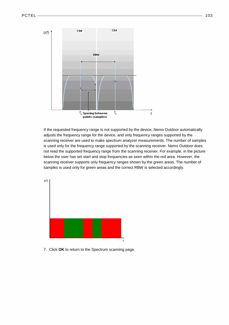
PCTEL 103
If the requested frequency range is not supported by the device, Nemo Outdoor automatically adjusts the frequency range for the device, and only frequency ranges supported by the scanning receiver are used to make spectrum analyzer measurements. The number of samples is used only for the frequency range supported by the scanning receiver. Nemo Outdoor does not read the supported frequency range from the scanning receiver. For example, in the picture below the user has set start and stop frequencies as seen within the red area. However, the scanning receiver supports only frequency ranges shown by the green areas. The number of samples is used only for green areas and the correct RBW is selected accordingly.
7. Click OK to return to the Spectrum scanning page.
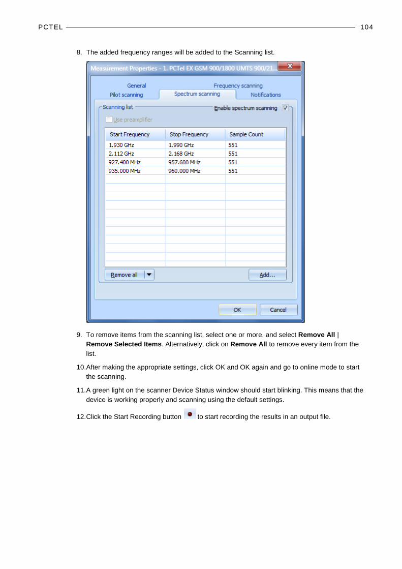
PCTEL 104
8. The added frequency ranges will be added to the Scanning list.
9. To remove items from the scanning list, select one or more, and select Remove All | Remove Selected Items. Alternatively, click on Remove All to remove every item from the list.
10. After making the appropriate settings, click OK and OK again and go to online mode to start the scanning.
11. A green light on the scanner Device Status window should start blinking. This means that the device is working properly and scanning using the default settings.
12. Click the Start Recording button to start recording the results in an output file.
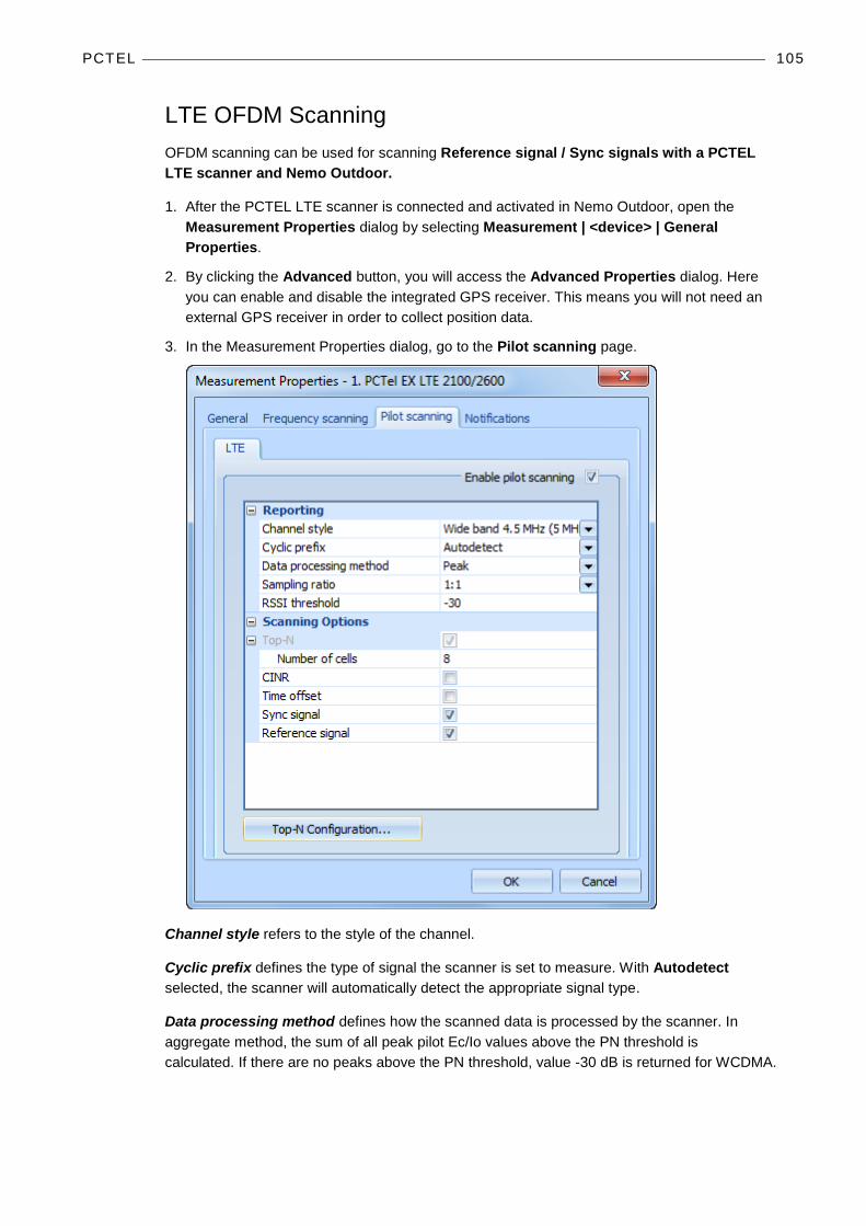
PCTEL 105
LTE OFDM Scanning OFDM scanning can be used for scanning Reference signal / Sync signals with a PCTEL LTE scanner and Nemo Outdoor.
1. After the PCTEL LTE scanner is connected and activated in Nemo Outdoor, open the Measurement Properties dialog by selecting Measurement | <device> | General Properties.
2. By clicking the Advanced button, you will access the Advanced Properties dialog. Here you can enable and disable the integrated GPS receiver. This means you will not need an external GPS receiver in order to collect position data.
3. In the Measurement Properties dialog, go to the Pilot scanning page.
Channel style refers to the style of the channel.
Cyclic prefix defines the type of signal the scanner is set to measure. With Autodetect selected, the scanner will automatically detect the appropriate signal type.
Data processing method defines how the scanned data is processed by the scanner. In aggregate method, the sum of all peak pilot Ec/Io values above the PN threshold is calculated. If there are no peaks above the PN threshold, value -30 dB is returned for WCDMA.
PCTEL 106
Sampling ratio option is available for PCTEL EX scanners only. The available options are 1:1, 1:2, 1:4 and 1:8. With ratio 1:1 all samples (Pilotscan events) are logged, with ratio 1:2 every second sample is logged, with ratio 1:4 every 4th sample is logged, and with ratio 1:8 every 8th sample is logged. By decreasing the sampling ratio you can decrease the output file size, but the scanning accuracy will be diminished.
RSSI threshold determines a valid path (in dB). Subtracting the set value from a path with a maximum correlation value gives the lower limit of the valid path.
Top-N option enables/disables Top-N scrambling code scanning. If enabled, scanner will report results from N best cells. Number of cells field indicates the number of best cells you want the scanning to notify you of. Up to 16 sectors are reported with specific cell ID.
CINR option activates/deactivates Carrier to Interference and Noise Ratio measuring. Carrier refers to either reference signal power or sync signal power depending on the selected signal type.
Time offset refers to the number of samples between P-SCH Primary Synchronization Signal arrival time with respect to receiver frequency reference that is derived from GPS reference time.
Sync signal refers to the ratio between the synchronization channel, i.e., primary and secondary signal received power and the interference and noise from the same synchronization signal set.
Reference signal refers to the ratio between the reference signal received power (RSRP) and the interference and noise from the same reference signal set.
The Top-N Configuration button will open the Select Channels where you can select channels for pilot scanning. The maximum number of channels that can be selected is device specific.
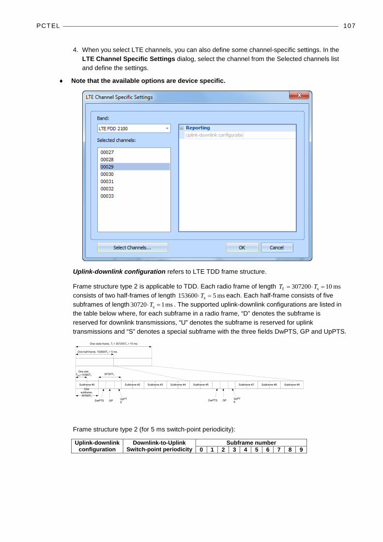
PCTEL 107
4. When you select LTE channels, you can also define some channel-specific settings. In the LTE Channel Specific Settings dialog, select the channel from the Selected channels list and define the settings.
♦ Note that the available options are device specific.
Uplink-downlink configuration refers to LTE TDD frame structure.
Frame structure type 2 is applicable to TDD. Each radio frame of length ms 10307200 sf =⋅= TT consists of two half-frames of length ms 5153600 s =⋅T each. Each half-frame consists of five subframes of length ms 107203 s =⋅T . The supported uplink-downlink configurations are listed in the table below where, for each subframe in a radio frame, “D” denotes the subframe is reserved for downlink transmissions, “U” denotes the subframe is reserved for uplink transmissions and “S” denotes a special subframe with the three fields DwPTS, GP and UpPTS.
One slot, Tslot=15360Ts
GP UpPTSDwPTS
One radio frame, Tf = 307200Ts = 10 ms
One half-frame, 153600Ts = 5 ms
30720Ts
One subframe, 30720Ts
GP UpPTSDwPTS
Subframe #2 Subframe #3 Subframe #4Subframe #0 Subframe #5 Subframe #7 Subframe #8 Subframe #9
Frame structure type 2 (for 5 ms switch-point periodicity):
Uplink-downlink configuration
Downlink-to-Uplink Switch-point periodicity
Subframe number 0 1 2 3 4 5 6 7 8 9

PCTEL 108
0 5 ms D S U U U D S U U U 1 5 ms D S U U D D S U U D 2 5 ms D S U D D D S U D D 3 10 ms D S U U U D D D D D 4 10 ms D S U U D D D D D D 5 10 ms D S U D D D D D D D 6 5 ms D S U U U D S U U D
5. After making the appropriate settings, click OK and OK again and go to online mode to start the scanning.
6. A green light on the scanner Device Status window should start blinking. This means that the device is working properly and scanning using the default settings.
7. Click the Start Recording button to start recording the results in an output file.
Pilot Scrambling Code Scanning Known Scrambling Code Scanning can be used to scan known pilots. The Known Scrambling Code Scanning will from now on be referred to as Normal Pilot Mode.
1. After the PCTEL LX scanner is connected and activated in Nemo Outdoor, open the Measurement Properties dialog by selecting Measurement | <device> | General Properties.
2. In the Measurement Properties dialog, go to the Pilot scanning page.

PCTEL 109
3. Clear the TOP-N mode option and click the Select Channels button. The Select Scrambling Codes dialog is opened.
4. Select channels in the Selected channel numbers table by clicking the Select button.
♦ With a PCTEL scanner a maximum of 8 channels can be selected in the pilot mode.
5. For each selected channel, select scrambling codes. Select a channel and click the Select button below the Selected scrambling codes table.
6. Click OK to return to the Measurement Properties dialog.
7. Data processing method defines how the scanner will process samples before reporting.
8. PN threshold defines the limit above which Ec/N0 peaks must go if Aggregated data processing method is used.
♦ In Pilot Scanning Mode the RSSI is always measured for each channel.
♦ In Pilot Scanning Mode the P-CPICH Ec/N0 and RSCP are always measured for each scrambling code.
9. After making the appropriate settings, click OK and OK again and go to online mode to start the scanning.
10. A green light on the scanner Device Status window should start blinking. This means that the device is working properly and scanning using the default settings. In TOP-N Mode this may take a few seconds.
11. Click the Start Recording button to start recording the results in an output file.

Rohde & Schwarz 110
ROHDE & SCHWARZ
CONNECTING THE ROHDE & SCHWARZ TSMQ/TSML SCANNER
♦ Note that your PC must have a FireWire (IEEE1394) port in it and a 32-bit PC FireWire controller card for you to be able to connect a Rohde & Schwarz TSMQ Scanner
1. First, install the TSMxDriverInstall.exe file on the installation CD.
2. Click Run to run the installation file.
3. Click Next in the Welcome window that appears.
4. Next, connect the antenna cable to the RF Input connector in the Rohde & Schwarz scanner.
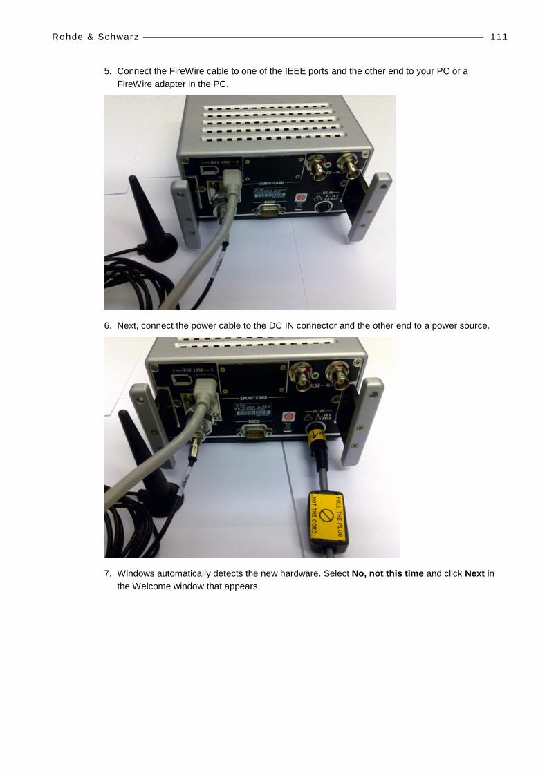
Rohde & Schwarz 111
5. Connect the FireWire cable to one of the IEEE ports and the other end to your PC or a FireWire adapter in the PC.
6. Next, connect the power cable to the DC IN connector and the other end to a power source.
7. Windows automatically detects the new hardware. Select No, not this time and click Next in the Welcome window that appears.

Rohde & Schwarz 112
8. Select Install the software automatically (Recommended), and click Next.
9. Click Finish to finish the installation.
10. Go to Device Manager from Start | Control Panel | System | Hardware | Device Manager. You should see the Rohde & Schwarz TSMx Devices item, and the applicable Rohde & Schwarz scanner model under it.

Rohde & Schwarz 113
CONNECTING THE ROHDE & SCHWARZ TSMW SCANNER 1. First, connect antenna cables to the RF1 and RF2 input connectors. See chapter System
Priority Order with R&S TSMW Scanners on page 115 for information on connecting the antennas to the correct ports.
2. Next, connect the network cable connector to the LAN connector in the scanner.
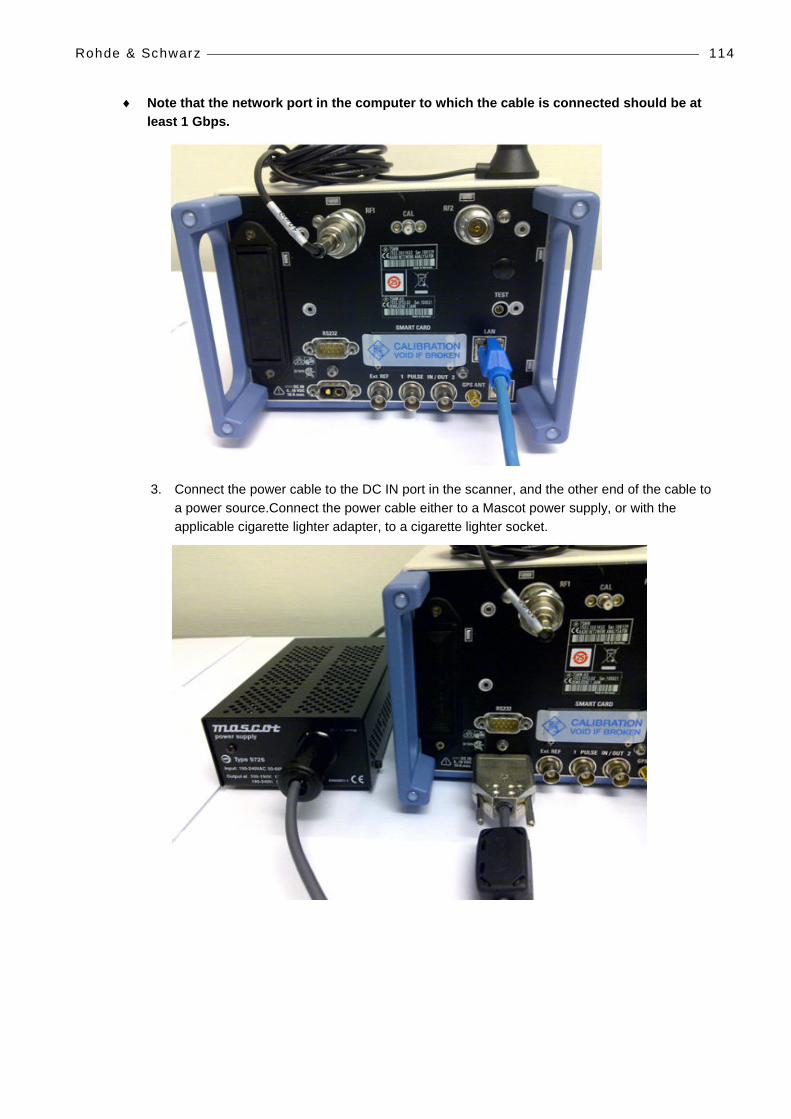
Rohde & Schwarz 114
♦ Note that the network port in the computer to which the cable is connected should be at least 1 Gbps.
3. Connect the power cable to the DC IN port in the scanner, and the other end of the cable to a power source.Connect the power cable either to a Mascot power supply, or with the applicable cigarette lighter adapter, to a cigarette lighter socket.
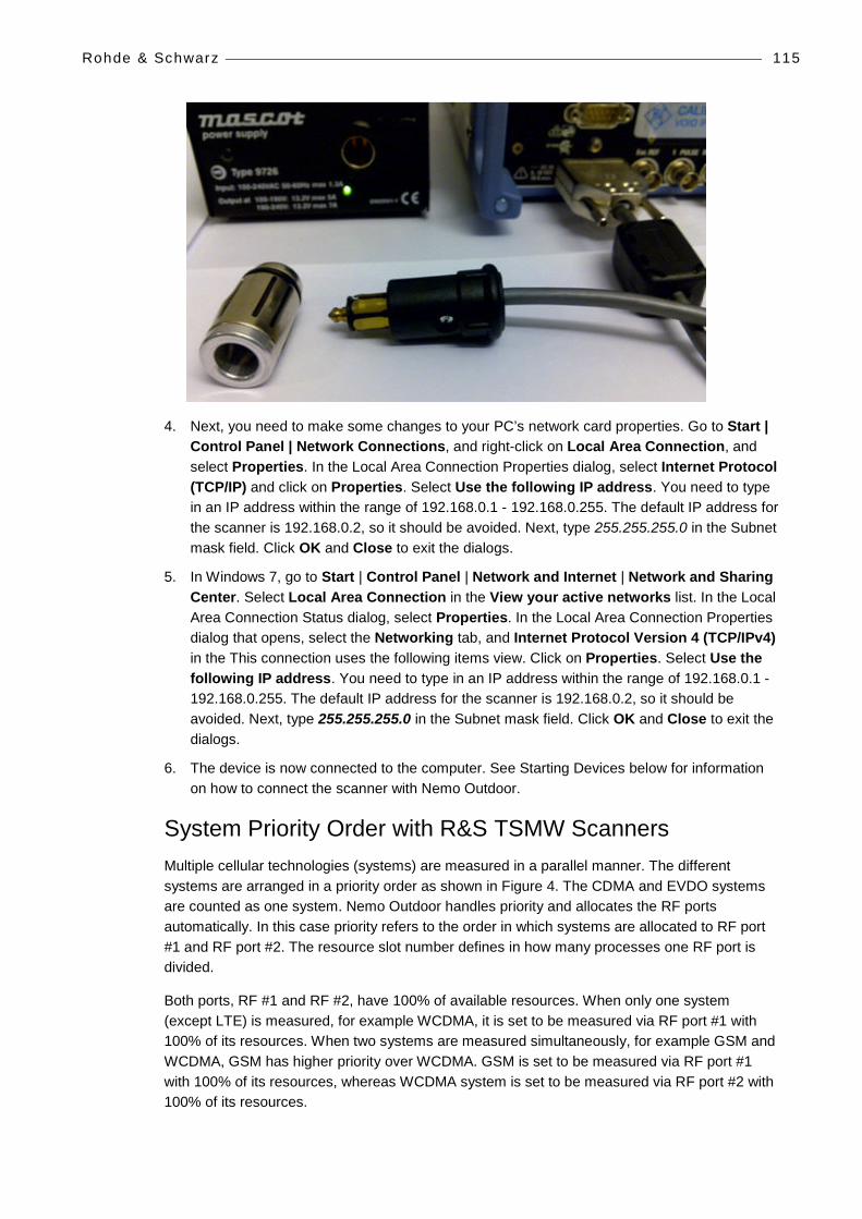
Rohde & Schwarz 115
4. Next, you need to make some changes to your PC’s network card properties. Go to Start | Control Panel | Network Connections, and right-click on Local Area Connection, and select Properties. In the Local Area Connection Properties dialog, select Internet Protocol (TCP/IP) and click on Properties. Select Use the following IP address. You need to type in an IP address within the range of 192.168.0.1 - 192.168.0.255. The default IP address for the scanner is 192.168.0.2, so it should be avoided. Next, type 255.255.255.0 in the Subnet mask field. Click OK and Close to exit the dialogs.
5. In Windows 7, go to Start | Control Panel | Network and Internet | Network and Sharing Center. Select Local Area Connection in the View your active networks list. In the Local Area Connection Status dialog, select Properties. In the Local Area Connection Properties dialog that opens, select the Networking tab, and Internet Protocol Version 4 (TCP/IPv4) in the This connection uses the following items view. Click on Properties. Select Use the following IP address. You need to type in an IP address within the range of 192.168.0.1 - 192.168.0.255. The default IP address for the scanner is 192.168.0.2, so it should be avoided. Next, type 255.255.255.0 in the Subnet mask field. Click OK and Close to exit the dialogs.
6. The device is now connected to the computer. See Starting Devices below for information on how to connect the scanner with Nemo Outdoor.
System Priority Order with R&S TSMW Scanners Multiple cellular technologies (systems) are measured in a parallel manner. The different systems are arranged in a priority order as shown in Figure 4. The CDMA and EVDO systems are counted as one system. Nemo Outdoor handles priority and allocates the RF ports automatically. In this case priority refers to the order in which systems are allocated to RF port #1 and RF port #2. The resource slot number defines in how many processes one RF port is divided.
Both ports, RF #1 and RF #2, have 100% of available resources. When only one system (except LTE) is measured, for example WCDMA, it is set to be measured via RF port #1 with 100% of its resources. When two systems are measured simultaneously, for example GSM and WCDMA, GSM has higher priority over WCDMA. GSM is set to be measured via RF port #1 with 100% of its resources, whereas WCDMA system is set to be measured via RF port #2 with 100% of its resources.

Rohde & Schwarz 116
When three systems are measured simultaneously, for example GSM, WCDMA and CDMA, the systems are again allocated in the priority order for the two RF ports. In this case RF port #1 is shared by two systems: GSM and CDMA. Each system gets 50% of the RF port #1 resources. 100% of RF port #2 resources are allocated to WCDMA measurements.
With LTE, individual carriers are allocated to the two RF ports. For example, when measuring two or more LTE carriers, carriers are arranged in order from lowest frequency number to the highest. After that, carriers (frequencies) are allocated to the RF ports so that the first carrier is allocated to RF port #1 and the second carrier to RF port #2, third carrier is again allocated to RF port #1 and the fourth carrier to RF port #2, etc.
If the measurement setup includes an odd number of other systems in addition to LTE, the first LTE carrier is allocated to RF port #2. The second LTE carrier is allocated to RF port #1, etc. However, if the measurement setup includes only one other system in addition to LTE, the other system is allocated to RF port #1 and all LTE carriers are allocated to RF port #2.
Spectrum scanning is counted as one of the systems. Spectrum scanning always has the highest priority and it is set to be measured via RF port #1. The resource slot number defines in how many processes one RF port is divided.

Rohde & Schwarz 117
CONNECTING ROHDE & SCHWARZ SCANNERS TO NEMO INVEX CHASSIS
♦ Please note that R&S TSMQ and TSML scanners cannot be connected to Nemo Invex. They must be connected to the measurement laptop. You should also connect an external GPS receiver to the laptop in order to log geographical coordinates.
Rohde&Schwarz TSMW scanners can be attached on top of the Nemo Invex chassis with a mounting plate.

Rohde & Schwarz 118
Connecting R&S TSMW to Nemo Invex with an Ethernet Cable Rohde&Schwarz TSMW scanner is connected to the Nemo Invex chassis (SI module) with an Ethernet cable.
After you have connected the TSMW scanner to Invex, you will need to change the IP address of Nemo Invex to match the IP address of the scanner. This requires a USB memory key.
1. Create a folder named Nemo Invex on the USB memory key.
2. Create a new file named SetIPAddress.txt.
3. Open the txt file and type the new IP address in the following format Base_IP,Subnet mask,Gateway
4. For example, the default Nemo Invex IP address must be changed from 192.168.3.210 to 192.168.0.3. Type 192.168.0.3,255.555.254.0,192.168.1.1. Save and close the txt file.
5. Connect the USB memory key to the USB-1 port on the UIC 1 module of your Nemo Invex chassis.
6. Wait until red LEDs are blinking and the shut down the chassis.
7. Remove the USB memory key.
8. The new IP address is assigned before the Nemo Measurement server starts up.
9. For other UICs IP address is incremented by one automatically.
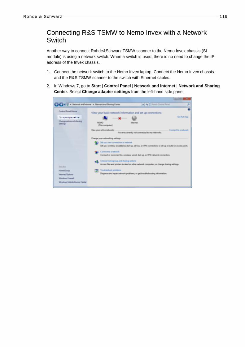
Rohde & Schwarz 119
Connecting R&S TSMW to Nemo Invex with a Network Switch Another way to connect Rohde&Schwarz TSMW scanner to the Nemo Invex chassis (SI module) is using a network switch. When a switch is used, there is no need to change the IP address of the Invex chassis.
1. Connect the network switch to the Nemo Invex laptop. Connect the Nemo Invex chassis and the R&S TSMW scanner to the switch with Ethernet cables.
2. In Windows 7, go to Start | Control Panel | Network and Internet | Network and Sharing Center. Select Change adapter settings from the left-hand side panel.

Rohde & Schwarz 120
3. Right-click on Local Area Connection and select Properties. In the Local Area Connection Properties dialog, double-click the Internet Protocol Version 4 (TCP/IPv4).

Rohde & Schwarz 121
4. In the Internet Protocol Version 4 Properties dialog, select Use the following IP address and click on Advanced.
5. In the Advanced TCP/IP Settings dialog, click Add.

Rohde & Schwarz 122
6. First type in an IP address for the Invex chassis within the range of 192.168.3.1 - 192.168.3.255. Next, type 255.255.255.0 in the Subnet mask field. Click Add. The address is added in the IP addresses field.
7. Now click Add again to add the IP address for the R&S TSMW scanner. Type in an IP address for the scanner within the range of 192.168.0.1 - 192.168.0.255. The default IP address for the scanner is 192.168.0.2, so it should be avoided. Next, type 255.255.255.0 in the Subnet mask field. Click Add. The address is added in the IP addresses field. Click OK and OK.

Rohde & Schwarz 123
STARTING ROHDE & SCHWARZ SCANNERS 1. Start Nemo Outdoor. Do not load any previous device configuration if asked.
2. From the Measurement menu, select Add New Device.
3. Click on Scanner.
4. From the list select the applicable R&S scanner, and click Next..
5. In the Scanner Properties dialog, select R&S IEEE1394A in the Port drop-down menu and click OK. With the TSMW scanner, select one of the following:
• R&S LAN = 192.168.0.2
• R&S LAN 2 = 192.168.0.3
• R&S LAN 3 = 192.168.0.4
• R&S LAN 4 = 192.168.0.5

Rohde & Schwarz 124
6. A green light should be blinking in the Device Status for both devices. This means that the devices are working properly and scanning using the default settings. If the status field displays, Device is not started, check that you are in online mode (click the Work Offline/Online button ).

Rohde & Schwarz 125
MEASURING WITH ROHDE & SCHWARZ SCANNERS With Rohde & Schwarz TSMQ, TSML and TSMW scanners you can perform GSM frequency scanning, GSM/UMTS scanning, CDMA TOP-N Pilot scanning, EVDO TOP-N Pilot scanning, UMTS TOP-N Pilot scanning, and Spectrum scanning. In addition, it is possible to perform CW scanning measurements with the TSMQ and TSML scanners and LTE measurements with the TSMW scanner. It is possible to perform any of the measurements introduced below separately, any combination of the measurements or all of them simultaneously.
Frequency Scanning 1. After the Rohde & Schwarz TSMQ/TSML scanner is connected and activated in Nemo
Outdoor, open the Measurement Properties dialog by selecting Measurement | <device> | General Properties.
Selecting the BSIC decoding option displays BSIC value in a measurement window.
BSIC threshold defines the minimum BSIC level that the scanner reports.

Rohde & Schwarz 126
Select the BCCH C/I option to activate C/I measurements for the BCCH channel. This option is available with the PCTEL GSM scanner only.
Cell information decoding. Mobile Network Code, Mobile Country Code and Cell ID information can be decoded from BCCH messages. Note that this is only enabled in online mode and if the option has been purchased with the scanner.
When the System information decoding option is selected, L3 messages are written in the log file.
2. Click the Select Channels button to open the Select Channels dialog.
3. The table displays the channel numbers, not the frequencies.
4. Select one band from the Band list or all of them. You can also select one band at a time and add the bands you want to scan. If all bands are selected, you have the possibility to select Remove All | ... items from every band. Alternatively, if only one band is selected you can remove only items from the current band through Remove All |...items from current band.
5. Remove channels from the Selected list by selecting a channel and clicking the Remove button.
6. Add channels to the Selected list by selecting a channel from the Available list and clicking the Add button.

Rohde & Schwarz 127
7. Click OK to return to the Measurement Properties dialog.
8. After making the appropriate settings, click OK and OK again and go to online mode to start the scanning.
9. A green light on the scanner Device Status window should start blinking. This means that the device is working properly and scanning using the default settings. In TOP-N Mode this may take a few seconds.
10. Click the Start Recording button to start recording the results in an output file.
TOP-N Pilot Scanning - UMTS 1. Open the Measurement Properties dialog by selecting Measurement | <device> | General
Properties.
2. Go to the Pilot scanning, UMTS page to define UMTS-specific Pilot scanning settings.
CPICH Ec/No threshold defines the minimum level for the CPICH Ec/No. If the values are below the threshold, the pilots are not reported.
Channel style refers to the style of the channel.
Rohde & Schwarz 128
Data processing method defines how the scanned data is processed by the scanner. In aggregate method, the sum of all peak pilot Ec/Io values above the PN threshold is calculated. If there are no peaks above the PN threshold, value -30 dB is returned for WCDMA.
Pilot measurement mode defines the measurement mode for pilot scanning.
• In High speed mode scanning speed is higher but sensitivity is lower. In high speed mode, weak pilots may be undetected.
• In High dynamic mode scanning speed is lower but sensitivity is higher.
Top-N option enables/disables Top-N scrambling code scanning. If enabled, scanner will report results from N best scrambling codes. Number of pilots field defines how many pilots are reported by scanner in Top-N mode.
♦ Note that the Rohde & Schwarz TSMQ, TSML-W, TSML-GW and TSMW scanners support only TOP-N mode and High speed and High dynamic pilot measurement modes. In addition, Data processing method and CPICH Ec/N0 threshold are supported general settings, and P-SCH, S-SCH, Time of arrival, Delay spread and SIR are supported of the scanning options.
Time of arrival defines if the selected scanner will measure the time of arrival for each scrambling code. The time of arrival value is relative to GPS time and is measured in chips.
Delay spread defines if the selected scanner will also measure the delay spread value (in chips) for each scanned scrambling code. Delay spread is determined as the difference between the last and first component to break the threshold set in PN Threshold.
When the Missing neighbor detection option is selected, the missing neighbor information event (NMISS) is written in the log file. You can view the missing neighbor information, for example, in a grid view.
When the Neighbor list decoding option is selected, the NLIST (neighbor list) event is written in the log file for both GSM and WCDMA.
Delay profile option enables/disables delay profile scanning. The Channel number field provides a list of channels that can be selected for scanning.
P-SCH defines if the selected scanner will measure the P-SCH Ec/N0 value for each scrambling code.
SIR (signal to interference ratio) defines if the selected scanner will measure the SIR value for each scrambling code.
S-SCH defines if the selected scanner will measure the S-SCH Ec/N0 value for each scrambling code.
When the System information decoding option is selected, L3 messages are written in the log file.
The Top-N Configuration button will open the Select Channels dialog where you can select channels for pilot scanning.
♦ Note that with UMTS the maximum number of channels that can be scanned is 32 channels, and the maximum number of pilots per each channel is 32.

Rohde & Schwarz 129
3. After making the appropriate settings, click OK and OK again and go to online mode to start the scanning.
4. A green light on the scanner Device Status window should start blinking. This means that the device is working properly and scanning using the default settings. In TOP-N Mode this may take a few seconds.
5. Click the Start Recording button to start recording the results in an output file.
TOP-N Pilot Scanning - CDMA/EVDO ♦ Note that the EVDO measurements can only be performed in a proper way when a CDMA
2000 channel is measured as well. In this way, the time relationship between the different PN offsets is resolved.
1. After the Rohde & Schwarz TSMQ scanner is connected and activated in Nemo Outdoor, open the Measurement Properties dialog by selecting Measurement | <device> | General Properties.
2. In the Measurement Properties dialog, go to the Pilot Scanning, CDMA page.
Pilot Ec/I0 threshold defines the threshold level for the pilot Ec/I0. If the values are below the threshold, the pilots are not scanned.

Rohde & Schwarz 130
TOP-N mode option enables/disables TOP-N scrambling code scanning. Number of pilots field defines how many pilots are reported by the scanner in TOP-N mode.
Overhead message decoding, when selected, enables the scanner to decode PCH messages.
The Top-N Configuration button will open the Select Channels dialog where you can select channels for pilot scanning.
♦ Note that the Rohde & Schwarz TSMQ scanner supports max 32 channels.
3. After making the appropriate settings, click OK and OK again and go to online mode to start the scanning.
4. A green light on the scanner Device Status window should start blinking. This means that the device is working properly and scanning using the default settings. In TOP-N Mode this may take a few seconds.
5. Click the Start Recording button to start recording the results in an output file.

Rohde & Schwarz 131
TOP-N Pilot Scanning - LTE 1. Open the Measurement Properties dialog by selecting Measurement | <device> | General
Properties.
2. Go to the Pilot scanning, LTE page to define LTE-specific pilot scanning settings.
CINR option activates/deactivates Carrier to Interference and Noise Ratio measuring. Carrier refers to either reference signal power or sync signal power depending on the selected signal type.
Sync signal refers to the ratio between the synchronization channel, i.e., primary and secondary signal received power and the interference and noise from the same synchronization signal set.
Reference signal refers to the ratio between the reference signal received power (RSRP) and the interference and noise from the same reference signal set.
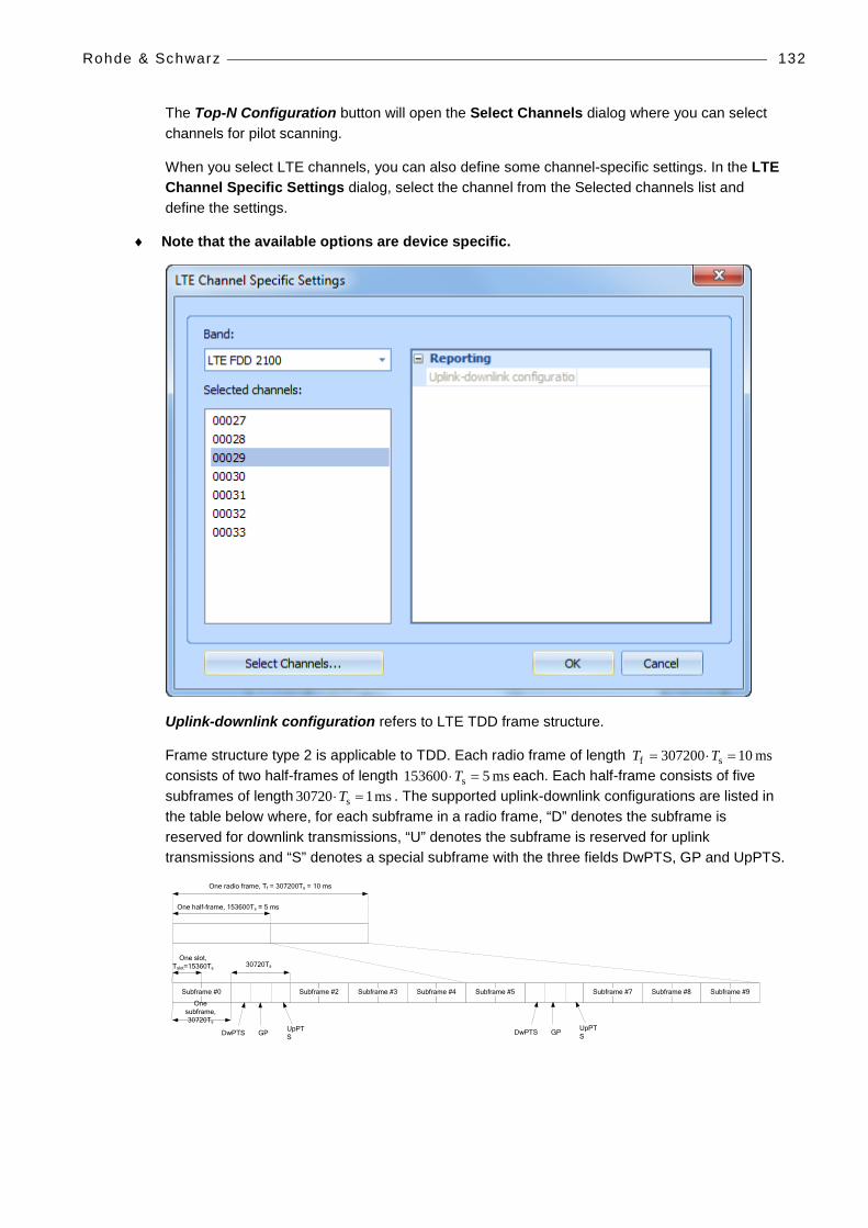
Rohde & Schwarz 132
The Top-N Configuration button will open the Select Channels dialog where you can select channels for pilot scanning.
When you select LTE channels, you can also define some channel-specific settings. In the LTE Channel Specific Settings dialog, select the channel from the Selected channels list and define the settings.
♦ Note that the available options are device specific.
Uplink-downlink configuration refers to LTE TDD frame structure.
Frame structure type 2 is applicable to TDD. Each radio frame of length ms 10307200 sf =⋅= TT consists of two half-frames of length ms 5153600 s =⋅T each. Each half-frame consists of five subframes of length ms 107203 s =⋅T . The supported uplink-downlink configurations are listed in the table below where, for each subframe in a radio frame, “D” denotes the subframe is reserved for downlink transmissions, “U” denotes the subframe is reserved for uplink transmissions and “S” denotes a special subframe with the three fields DwPTS, GP and UpPTS.
One slot, Tslot=15360Ts
GP UpPTSDwPTS
One radio frame, Tf = 307200Ts = 10 ms
One half-frame, 153600Ts = 5 ms
30720Ts
One subframe, 30720Ts
GP UpPTSDwPTS
Subframe #2 Subframe #3 Subframe #4Subframe #0 Subframe #5 Subframe #7 Subframe #8 Subframe #9
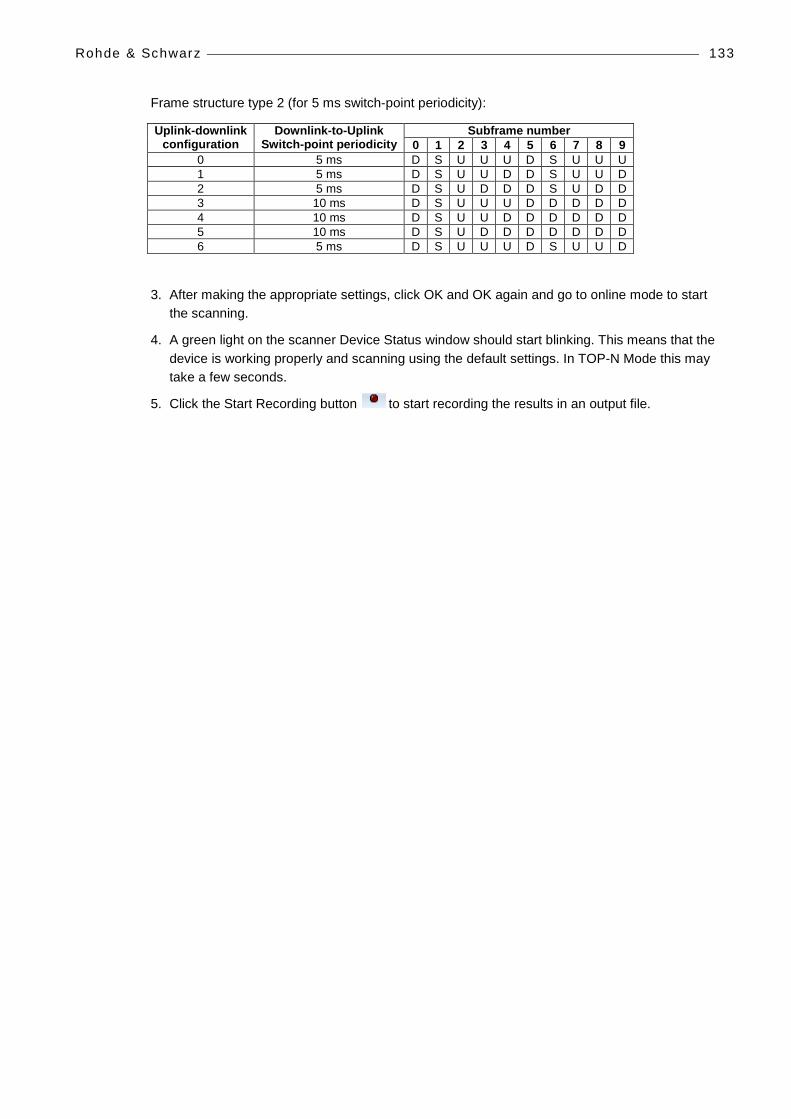
Rohde & Schwarz 133
Frame structure type 2 (for 5 ms switch-point periodicity):
Uplink-downlink configuration
Downlink-to-Uplink Switch-point periodicity
Subframe number 0 1 2 3 4 5 6 7 8 9
0 5 ms D S U U U D S U U U 1 5 ms D S U U D D S U U D 2 5 ms D S U D D D S U D D 3 10 ms D S U U U D D D D D 4 10 ms D S U U D D D D D D 5 10 ms D S U D D D D D D D 6 5 ms D S U U U D S U U D
3. After making the appropriate settings, click OK and OK again and go to online mode to start the scanning.
4. A green light on the scanner Device Status window should start blinking. This means that the device is working properly and scanning using the default settings. In TOP-N Mode this may take a few seconds.
5. Click the Start Recording button to start recording the results in an output file.

Rohde & Schwarz 134
Spectrum Scanning 1. After the Rohde & Schwarz scanner is connected and activated in Nemo Outdoor, open the
Measurement Properties dialog by selecting Measurement | <device> | General Properties.
2. In the Measurement Properties dialog, go to the Spectrum scanning page.

Rohde & Schwarz 135
3. In the Measurement Properties dialog, select the Enable spectrum scanning option. Click Add.
4. To create new scanning sets, define the scanning frequencies in the Reporting view.
Set start and stop frequencies defines the frequency range that will be scanned.
Set center frequency and bandwidth defines the frequency range that will be scanned.
The Sample count field determines the sample count measured for the given frequency range.
With Rohde & Schwarz scanner receivers, the user can set the start and stop frequency between 80MHz and 3000MHz. Sample counts are divided to the frequency range defined by the user. The TSMx device has a native frequency resolution of 12.8 KHz. It should be noted that the frequency shift cannot be lower than 12.8kHz, which sets the number of sample count max. limit to 5000 samples. In case the selected frequency range and sample count require a frequency shift lower than 12.8kHz, the sample count is automatically decreased. The sweep speed, resolution bandwidth and sampling rate are fixed. The sweep speed is 1 GHz / 0.1 sec, the resolution bandwidth is fixed at 30 kHz.
For example, if the start frequency is 80 MHz, and the stop frequency is 100 MHz, the total measured bandwidth is 20 MHz. If the sample count is set to 20, power (RMS) is measured from a 1 MHz bandwidth. With the frequency shift of 12.8 KHz ~ 78 samples are taken from each 1 MHz bandwidth.
Rohde & Schwarz 136
The Add to scanning list menu enables you to decide whether the newly created scanning set is added to the scanning list, or saved as a predefined set also for later use.
The Predefined scanning sets can be used to quickly select the frequency range to be scanned. Select a set from the list, and click on Add to scanning list.
5. Click OK to access the Scanning list view.
6. The added frequency ranges will be added to the Scanning list.
7. To remove items from the scanning list, select one or more, and select Remove all | Remove selected items. Alternatively, click on Remove all to remove every item from the list.
8. After making the appropriate settings, click OK and OK again and go to online mode to start the scanning.
9. A green light on the scanner Device Status window should start blinking. This means that the device is working properly and scanning using the default settings. In TOP-N Mode this may take a few seconds.
10. Click the Start Recording button to start recording the results in an output file.

Troubleshoot ing 137
TROUBLESHOOTING SCANNERS
If a Scanner synchronization failed error message appears in the Output window, the scanner is working properly, but the scanner did not find strong enough a CPICH in a short time period. Nevertheless, the measurement will go on normally.
If a Scanner GPS locking failed error message appears in the Output window, the scanner is working properly, but the scanner GPS has no fix or is not connected. The measurement will go on normally, but the scanner accuracy is not as good as it is when the scanner GPS has a fix.
NEMO FSR1 If the Nemo FSR1 license information cannot be read by Nemo Outdoor, please check that the down converter is attached properly. If this does not help, it is possible that the down converter is damaged. Please contact Anite technical support for further advice.