Embed Size (px)
DESCRIPTION
Here are some additional materials from LTE Phy Engineering course delivered in August 2013 in Umeå, Sweden. If you are interested in attending top in class LTE/LTE-Advanced courses, please have a look http://is-wirelesstraining.com/course-map-2 or contact us directly: [email protected].
Citation preview

Technical content provided by IS-Wireless, www.is-wireless.com
OFDM Processing Chain (From Bits to Carrier Frequency)
101010011101….. Modulator
QPSK/16QAM/64QAM S/P IFFT P/S
CP D/A Upconverter
(Local Oscillator)
X1 X2 X3 X4 … XN
X1
X2
X3
X4
…
XN
x1
x2
x3
x4
…
xN
xN … x4 x3 x2 x1
t I
Q
xN … x4 x3 x2 x1 xN xN-1
t
t
t
fc
t
f 0MHz
BW
f fc
BW
0MHz

Technical content provided by IS-Wireless, www.is-wireless.com
1 Radio Frame (10 ms)
1 subframe (1 ms)
1 slot (0.5 ms)
Slot =
7 OFDM symbols
(Normal CP)
CP CP CP CP CP CP Useful Part
CP Useful Part CP Useful Part CP Useful Part CP Useful Part CP Useful Part CP Useful Part CP Useful Part
1 OFDM symbol (83μs)
1 OFDM symbol (71μs)
Frame =
10 subframes
Subframe =
2 slots
Slot =
6 OFDM symbols
(Extended CP)
or
Useful Part Useful Part Useful Part Useful Part Useful Part
Radio Frame Time Structure

Technical content provided by IS-Wireless, www.is-wireless.com
1 Symbol in the frequency domain
Subcarrier (SC)
BW: 1.4MHz = 128 SC (72 useful SC)
3MHz = 256 SC (180 useful SC)
5MHz = 512 SC (300 useful SC)
10MHz = 1024 SC (600 useful SC)
15MHz = 1536 SC (900 useful SC)
20MHz = 2048 SC (1200 useful SC)
Smallest allocation
12 SCs (180kHz)
Guardband
(not used SCs) Guardband
(not used SCs)
DC subcarrier
(not used in DL)
Pilot subcarrier
(QPSK symbol)
Data Subcarrier
(QPSK/16QAM/64QAM symbol)
Useful Subcarriers
Radio Frame Frequency Structure

Technical content provided by IS-Wireless, www.is-wireless.com
TDD E-UTRA Radio Frame Downlink Frame Parts (e.g. Configuration 1)
1 slot (0.5 ms)
Control Region:
First 1-3 OFDM Symbols in subframe (for DwPTS 1-2 Symbols)
PCFICH – OFDM symbol 0,
PHICH – OFDM symbol 0
PDCCH – the rest
PBCH – 4 OFDM symbols (0-3)
in slot 1 in subframe 0
Synchronization Signals:
P-SS – OFDM symbol 2 in subframe 1 and 6
S-SS – OFDM symbol 13 in subframe 0 and 5
BW
PDSCH – rest REs
DC
1 subframe (1 ms)
62
SCs
72
SCs
1 Radio Frame (10 ms)
12 SC
7 OFDM Symbols
RS RE
2 PRB
OFDM Subcarrier
OFDM Symbol
Guard Band
for S-SS or P-SS
UL T
ransm
issio
n
UL T
ransm
issio
n
DwPTS
Technical content provided by IS-Wireless, www.is-wireless.com
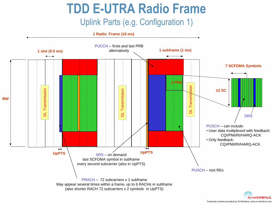
TDD E-UTRA Radio Frame Uplink Parts (e.g. Configuration 1)
DL T
ransm
issio
n
PUCCH – firsts and last PRB
alternatively
SRS – on demand
last SCFDMA symbol in subframe
every second subcarrier (also in UpPTS)
12 SC
1 slot (0.5 ms)
2 PRB
PUSCH – rest REs
1 Radio Frame (10 ms)
1 subframe (1 ms)
BW
PRACH – 72 subcarriers x 1 subframe
May appear several times within a frame, up to 6 RACHs in subframe
(also shorter RACH 72 subcarriers x 2 symbols in UpPTS)
DRS
7 SCFDMA Symbols
PUSCH – can include:
• User data multiplexed with feedback:
CQI/PMI/RI/HARQ-ACK
• Only feedback:
CQI/PMI/RI/HARQ-ACK
UpPTS UpPTS
DL T
ransm
issio
n
DL T
ransm
issio
n

Technical content provided by IS-Wireless, www.is-wireless.com
TDD E-UTRA Radio Frame DL and UL Subframe Configuration 1
1 slot (0.5 ms)
BW
DC
1 subframe (1 ms)
62
SCs
72
SCs
1 Radio Frame (10 ms)
DwPTS
Downlink
SF
UpPTS GP
Special
SF Uplink
SF
Uplink
SF Downlink
SF
Downlink
SF Special
SF
Uplink
SF
Uplink
SF Downlink
SF

Technical content provided by IS-Wireless, www.is-wireless.com
LTE Rel. 8 Duplex Types
Frequency Division Duplex
Half-duplex FDD
DL: fC
UL: fC
DL: fC
UL: fC
Time Division Duplex
DL/UL: fC
FDD for
reduced
UE complexity
t
f
t
f
t
f
UL and DL
selected from
different
frequency
bands
UL and DL
use the same
frequency
band divided
in time

Technical content provided by IS-Wireless, www.is-wireless.com
LTE Rel. 8 Radio Frame Differences Between FDD and TDD
DL
U
L
FDD frame 10ms frame
TDD frame (example configuration)
DL
/UL
One half frame (5ms)
10ms frame
1ms subframe
1ms subframe
Control Region (CR)
DL resource allocation ptr
UL resource allocation ptr
Special Subframe
0 1 2 3 4 5 6 7 8 9 # Subframe
DL/UL Switch
FDD DL/UL resource allocations:
single allocation PDCCH – single PDSCH/PUSCH
TDD DL resource allocation:
single allocation PDCCH – single PDSCH
TDD UL resource allocation
possible single allocation PDCCH – for multiple PUSCHs (for UL heavy conf)
DL:D
CI s
ubfra
me n
, allo
c s
ubfra
me n
UL: D
CI s
ubfra
me n
, allo
c s
ubfra
me n
+4
D
L:D
CI s
ubfra
me n
, allo
c s
ubfra
me n
UL: D
CI s
ubfra
me n
, allo
c s
ubfra
me n
+k (k
=4
-7)
P-SS
S-SS
Different placement of sync signals
After synchronization UE knows
already if this is TDD or FDD system

Technical content provided by IS-Wireless, www.is-wireless.com
E-UTRA TDD Radio Frame Configurations
DL/UL configuration is broadcasted in SIB 1 (subframe #5)
Configuration 0
DL:UL 2:3 (UL HEAVY)
Configuration 1
DL:UL 3:2
Configuration 2
DL:UL 4:1
5ms half frame
10ms frame
Configuration 3
DL:UL 7:3
Configuration 4
DL:UL 8:2
Configuration 5
DL:UL 9:1 (DL HEAVY)
Configuration 6
DL:UL 5:5
5 ms switch periodicity configurations
10 ms switch periodicity configurations Guard period
Downlink
Uplink
1ms subframe
0 1 2 3 4 5 6 7 8 9 # Subframe
Special Subframe Special Subframe

Technical content provided by IS-Wireless, www.is-wireless.com
Special Subframe Structure and Configurations
Special switching subframes #1 and #6
UpPTS DwPTS GP
Subframe (1ms), 14 OFDM Symbols
Downlink Pilot Time Slot
Guard Period
Uplink Pilot Time Slot
DLUL switch time (no transmission)
To allow UE to switch from Rx to Tx
To support coexistence with other systems
Normal, but shorter DL subframe includes:
* Control region – 1 to 2 symbols
* P-SS
* PDSCH and RSs – 1 to 10 symbols
Possible Configurations (normal CP)
0 1 2 3 4 5 6 7 8 9 10 11 12 13
0 1 2 3 4 5 6 7 8
Symbol number
Configuration
PDCCH
PCFICH
PHICH
PDCCH or
PDSCH
P-SS
PDSCH
SRS or
PRACH
PDSCH

Technical content provided by IS-Wireless, www.is-wireless.com
E-UTRA Rel.8 MIMO Processing
OFDMA
Mod
OFDMA
Mod
FEC/
Mod FEC/
Mod
Layer Mapping
MIMO Precoding
Resource
Mapping
Resource
Mapping
Channel
Matrix
BS Tx UE Rx
OFDMA
deMod
OFDMA
deMod
deFEC/
deMod deFEC/
deMod
Layer deMapping
MIMO dePrecoding
Resource
deMapping
Resource
deMapping
Data bits Data bits Data bits Data bits
1 or 2
transport blocks
1 or 2 codewords
1 to 4 layers
1 to 4
antennas
MIMO Processing
Selection of
predefined Matrix
Selection of
technique
(SISO/
SM/TxDiv)
Channel
estimation
Synchronization
Channel
correction
CQI, ACK/NACK
PMI/RI
CQI
Feedback
Indicates
preferred
matrix
Indicates
number
of layers
Different RSs
placement
for accurate
channel estimation
mapping of symbols
into the transmit
antenna port
independently encoded
data block
Indicates good part
of the spectrum
Indicates achievable
spectral efficiency

Technical content provided by IS-Wireless, www.is-wireless.com
EUTRA MIMO MIMO Operation for SFBC
Layer Mapping
One codeword 2 Layers
MIMO Precoding
2 antennas
Matrix for 2 antennas Matrix for 4 antennas
Alamouti
with antennas switch
x4x3x2x1
x4 x3 x2 x1
x*3 -x*4 x*1 -x
* 2
x3 x1
x4 x2
Towards
Resource Mapping
Mapped to different SCs
2 antennas are used
in a single symbol
transmission

Technical content provided by IS-Wireless, www.is-wireless.com
EUTRA MIMO MIMO Operation for SM (1/2)
Precoding for CL SM (low speed scenario) Precoding for OL SM with large CDD (high speed scenario)
Precoding
matrix Large CDD
matrix
For CL UE indicates PMI – index of matrix W
Layer Mapping
2 codewords 3 Layers
MIMO Precoding
(W)
4 antennas
x2x1 z21 z11 x2 x1
y2 y1 Towards
Resource Mapping
y4y3y2y1 y4 y3
z22 z12
z23 z13
z24 z14
z1=Wv1
z2=Wv2
v1 v2
BS may or may not to use it
Technical content provided by IS-Wireless, www.is-wireless.com
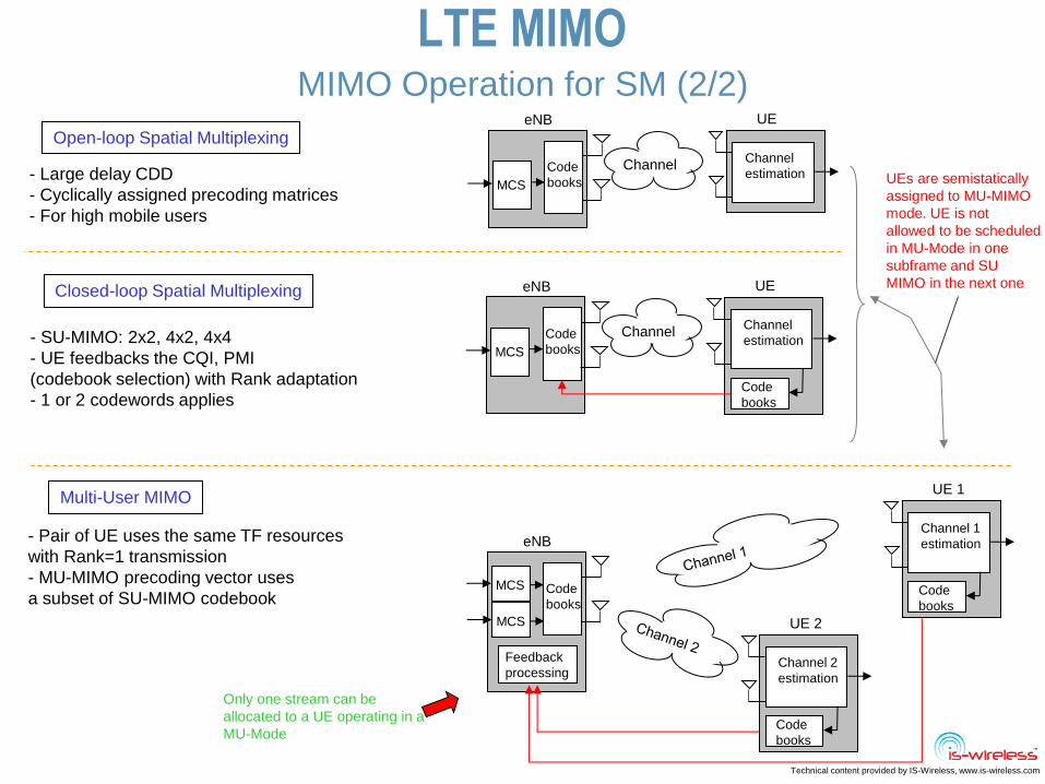
LTE MIMO
- Large delay CDD
- Cyclically assigned precoding matrices
- For high mobile users
- SU-MIMO: 2x2, 4x2, 4x4
- UE feedbacks the CQI, PMI
(codebook selection) with Rank adaptation
- 1 or 2 codewords applies
- Pair of UE uses the same TF resources
with Rank=1 transmission
- MU-MIMO precoding vector uses
a subset of SU-MIMO codebook
Open-loop Spatial Multiplexing
Closed-loop Spatial Multiplexing
Multi-User MIMO
MCS
eNB
Code
books
Channel
UE
Channel
estimation
Code
books
MCS
eNB
Code
books
MCS
Feedback
processing
UE 1
Channel 1
estimation
Code
books
UE 2
Channel 2
estimation
Code
books
MCS
eNB
Code
books
Channel
UE
Channel
estimation UEs are semistatically
assigned to MU-MIMO
mode. UE is not
allowed to be scheduled
in MU-Mode in one
subframe and SU
MIMO in the next one
Only one stream can be
allocated to a UE operating in a
MU-Mode
MIMO Operation for SM (2/2)

Technical content provided by IS-Wireless, www.is-wireless.com
LTE MIMO MIMO Operation for BF
Eigenbeamforming
Suitable precoding is chosen as a form of
eigenbeamforming for 1layer-1codeword
the same matrices as for SVD SM
Based on UE specific RS. UE sends in UL
then BS adjust RF parts.
Phased array appears at UE as a single
transmission, for UEs at cell edge
Layer Mapping
1 codeword 1 Layer
MIMO Precoding
(W)
4 antennas
z21 z11
x4x3x2 x1 Towards
Resource Mapping
z22 z12
z23 z13
z24 z14
z1=Wx1
z2=Wx2
x4x3x2 x1
DoA based beamforming
2 Types of BF
Specs don’t include exact definition of operation for these

Technical content provided by IS-Wireless, www.is-wireless.com
LTE MIMO Feedback Reporting
UE
eNB
UE
Rank Indication
Good uncorrelation
of spatial channels
(3 streams are transmitted)
Worse uncorrelation
of spatial channels
(2 streams can be transmitted)
Rank indication informs base station
how many layers/streams can it transmit
RI = 2
RI = 3
Precoding Matrix Indication
UE
eNB
UE
PMI = 0
PMI = 2
10
010P
11
112P
.
.
.
Channel realization 1
Matrix P2 applied
Channel realization 2
(conditions has changed)
Matrix P0 applied
Precoding matrix indication is used by the UE for pointing to the
selected codebook index for 2 and 4 antennas (only for SM)
Single RI per UE allocation Single PMI per UE allocation if allocated RB < 12,
per 5RB if allocated RB > 12
Minimum periodicity of the reports = 1subframe (1ms)
Examples
Examples

Technical content provided by IS-Wireless, www.is-wireless.com
LTE MIMO Spatial Mode Switching
Transmission mode Multi-antenna mode of PDSCH
1 Single-antenna port, port 0
2 Transmit diversity
3 Transmit diversity if the associated
rank indicator is 1, otherwise large
delay CDD
4 Closed-loop spatial multiplexing
5 Multi-user MIMO
6 Closed-loop spatial multiplexing
with a single transmission layer
7 If the number of PBCH antenna
ports is one, Single-antenna port,
port 0; otherwise Transmit diversity
FEC/
Modulator
SD
encoder
Tx Mode
Resource
Mapper
SM
Encoder
Resource
Mapper
IFFT
IFFT
Tx mode
selection
SD
layer mapper
SM
layer mapper
SNIR
Spectr
al E
ffic
iency
Switching point
(10dB – rule of thumb)
SM
SD

Technical content provided by IS-Wireless, www.is-wireless.com
LTE MIMO Rel. 8 Scenarios
eNB UE
eNB
UE
UE
eNB
UE
UE
eNB
UE
Space Diversity
DL: 2x1, 2x2, 4x1, 4x2, UL: 1x2, 1x4
Used for: PHICH, PCFICH, PDCCH, PBCH, PDSCH, PUSCH
Uncorrelated Channels (rich scattering)
Poor Channel (Fast variations)
Precoded 2 copies of the same signal
SFBC rank-1 transmission
Improved Link Reliability
SU-MIMO (Spatial Multiplexing) DL: 2x2, 4x2, 4x4
Used for: PDSCH (traffic)
Uncorrelated Channels (rich scattering)
Good Channel (slow variations)
Precoded 2 different streams
Increase in throughput
MU-MIMO (Spatial Multiplexing) DL: 2x1, UL: 1x2
Used for: PDSCH(traffic)
Uncorrelated Channels (rich scattering)
Good Channels
Precoded 2 different streams for 2 users
Increase in system capacity
Beamforming DL: 2x1, 4x1, 8x1
Used for: PDSCH, PUSCH (traffic)
Uncorrelated Channels (between users)
Poor/Good channels (for each user)
Increase in coverage
Less interference
Detailed operation
not described in specs


![LTE PHY Layer Measurement Guide...4 LTE PHY Layer Measurement Guide LTE Downlink The LTE downlink can be set on six different frequency profiles, as follows: Channel Bandwidth [MHz]](https://img.dokumen.tips/doc/110x75/5e9903898496907a812cd628/lte-phy-layer-measurement-guide-4-lte-phy-layer-measurement-guide-lte-downlink.jpg)