Embed Size (px)
Citation preview
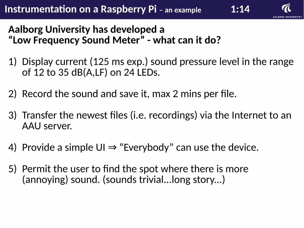
Aalborg University has developed a“Low Frequency Sound Meter” - what can it do?
1) Display current (125 ms exp.) sound pressure level in the range of 12 to 35 dB(A,LF) on 24 LEDs.
2) Record the sound and save it, max 2 mins per file.
3) Transfer the newest files (i.e. recordings) via the Internet to an AAU server.
4) Provide a simple UI “Everybody” can use the device.⇒
5) Permit the user to find the spot where there is more (annoying) sound. (sounds trivial...long story...)
Instrumentation on a Raspberry Pi – an example 1:14
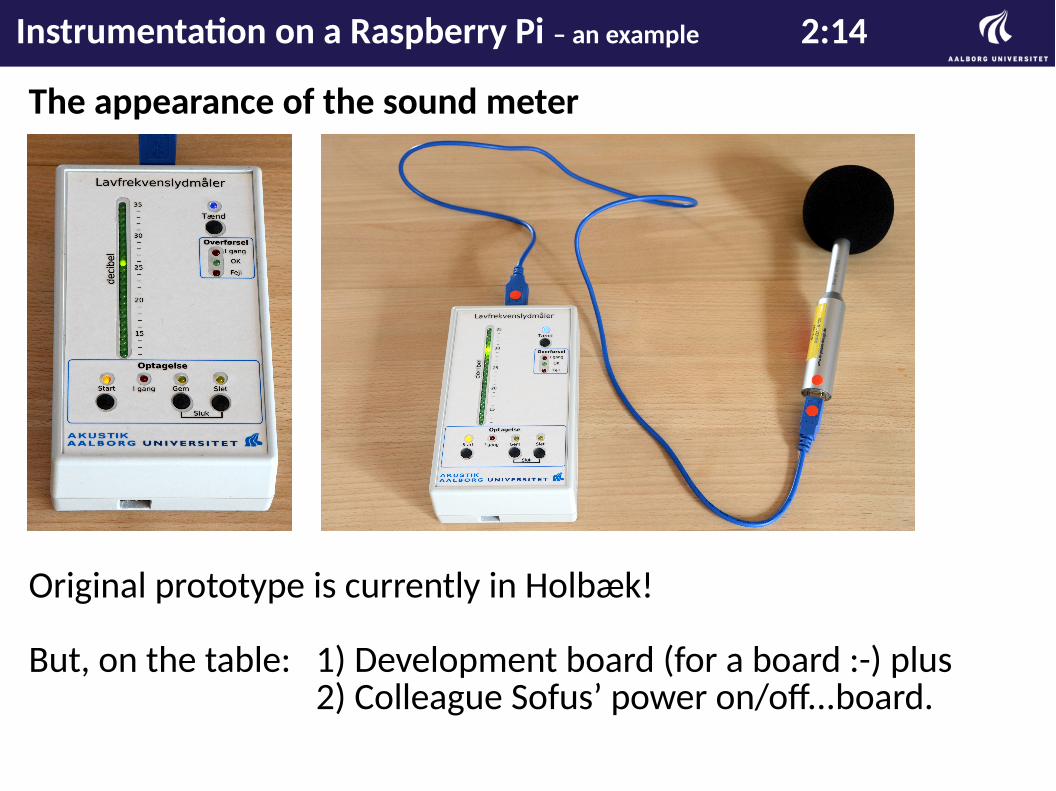
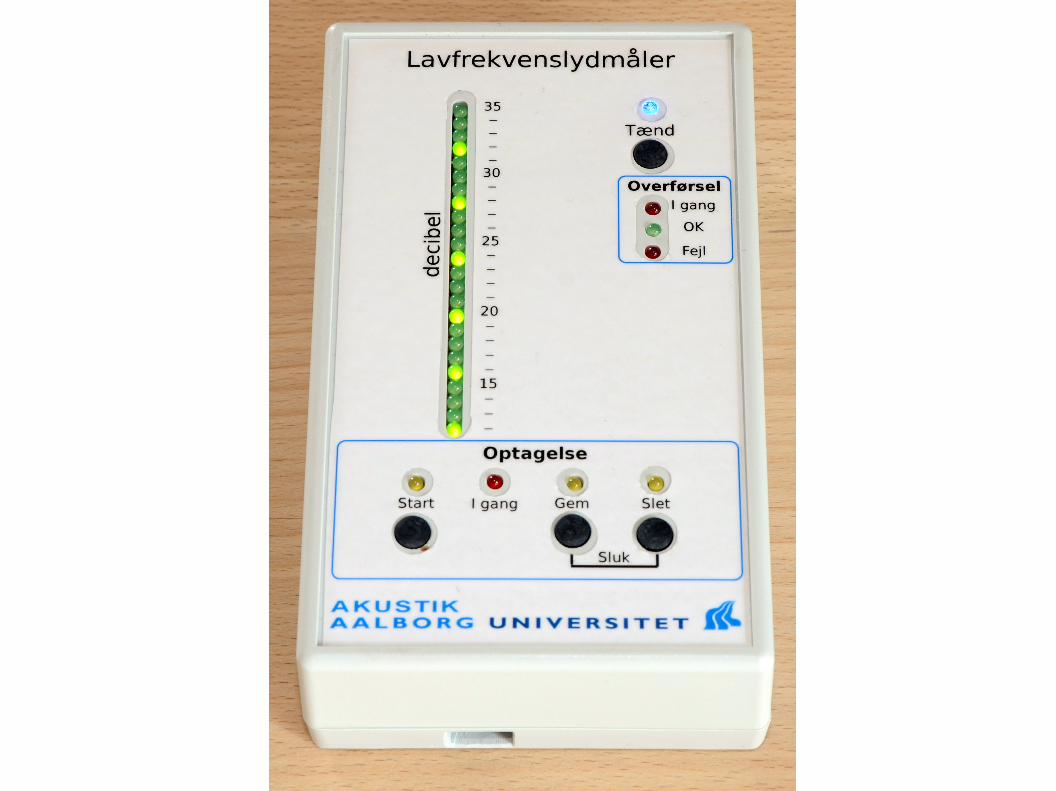
The appearance of the sound meter
Original prototype is currently in Holbæk!
But, on the table: 1) Development board (for a board :-) plus2) Colleague Sofus’ power on/off...board.
Instrumentation on a Raspberry Pi – an example 2:14
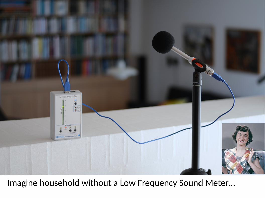
Imagine household without a Low Frequency Sound Meter…
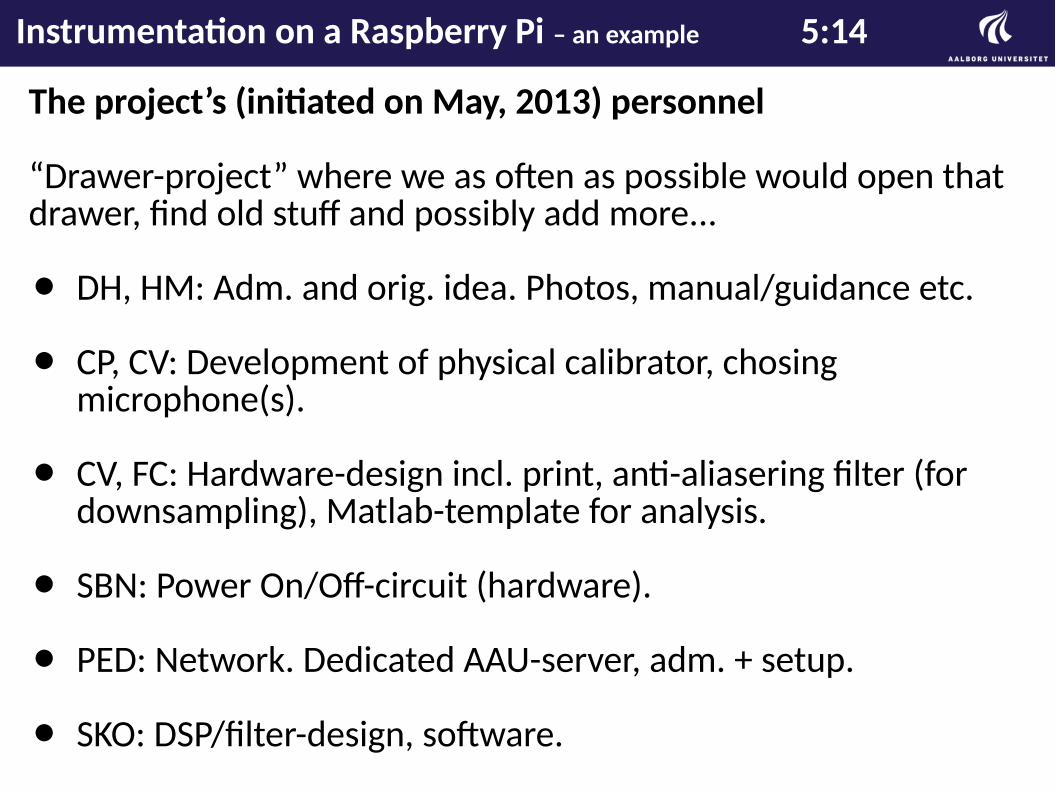
The project’s (initiated on May, 2013) personnel
“Drawer-project” where we as often as possible would open that drawer, find old stuff and possibly add more...
⚫ DH, HM: Adm. and orig. idea. Photos, manual/guidance etc.
⚫ CP, CV: Development of physical calibrator, chosing microphone(s).
⚫ CV, FC: Hardware-design incl. print, anti-aliasering filter (for downsampling), Matlab-template for analysis.
⚫ SBN: Power On/Off-circuit (hardware).
⚫ PED: Network. Dedicated AAU-server, adm. + setup.
⚫ SKO: DSP/filter-design, software.
Instrumentation on a Raspberry Pi – an example 5:14

No exact master plan
⚫ So...ideas were made up ad-hoc. E.g. the fact that all measurements should be recorded (and saved).
⚫ New ideas just called for new development which in turn called for new ideas etc.
⚫ Ending point: Lack of new ideas (never really happened).
Special features implemented
⚫ If a USB stick is inserted, all files would be copied there automatically; that was practical for debugging in general. Partly dropped in later versions.
⚫ If a camera USB cable is inserted the device would recognize that and copy all files on the camera to the SD-card on the system. Later to be sent via the Internet to the AAU server.
Instrumentation on a Raspberry Pi – an example 6:14
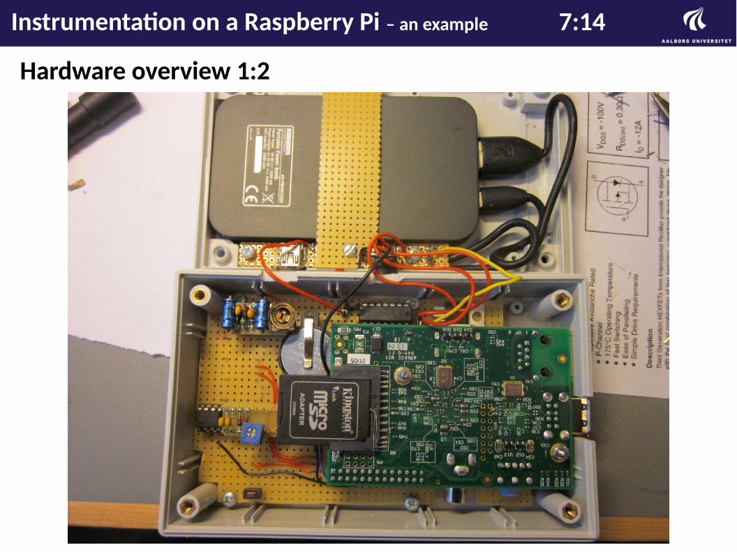
Hardware overview 1:2
Instrumentation on a Raspberry Pi – an example 7:14
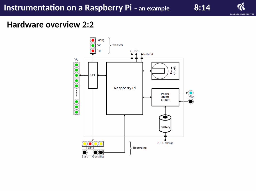
Hardware overview 2:2
Instrumentation on a Raspberry Pi – an example 8:14
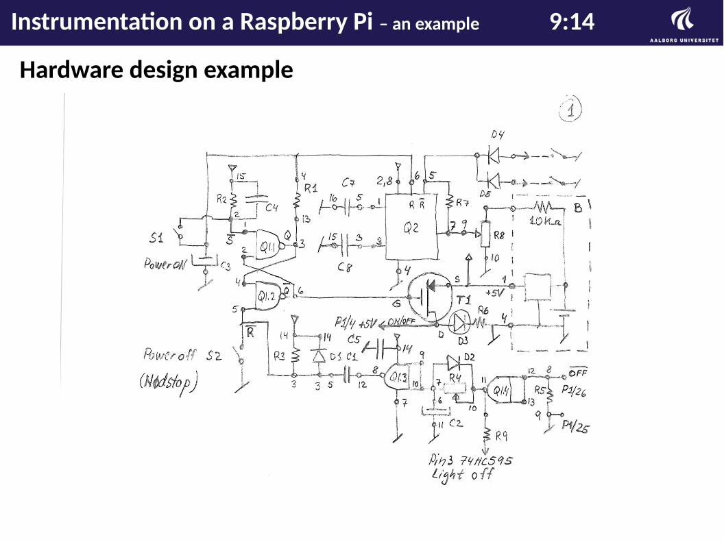
Hardware design example
Instrumentation on a Raspberry Pi – an example 9:14
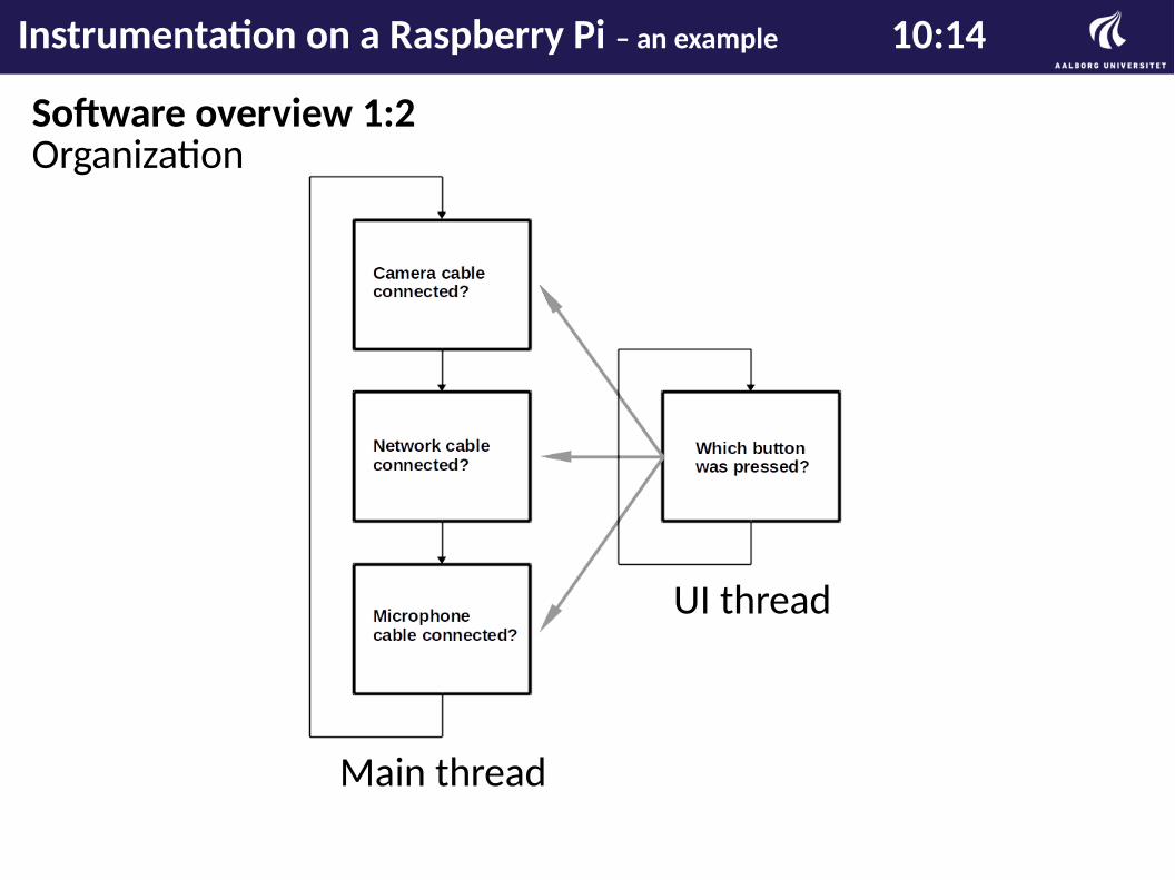
Software overview 1:2Organization
Main thread
UI thread
Instrumentation on a Raspberry Pi – an example 10:14
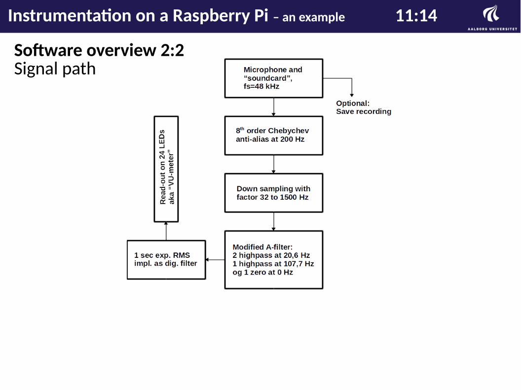
Software overview 2:2Signal path
Instrumentation on a Raspberry Pi – an example 11:14
Software requirements and considerations
⚫ Superior to existing...e.g. Gumsticks due to FP capabilites.
⚫ Raspian OS installed. Note: Pi3 has Wi-Fi but of no usage in this case. Everything must be cabled.
⚫ All C. No C++, Python whatever, yet, a few system() calls.
⚫ WiringPi. To access GPIOs more easily.
⚫ Advanced Linux Sound Architecture (ALSA).
Software problems
⚫ 44.1 vs. 48 kHz, zeros found in the sampled buffer.
⚫ A PC-emulator would have been nice + boot time smaller.
Instrumentation on a Raspberry Pi – an example 12:14
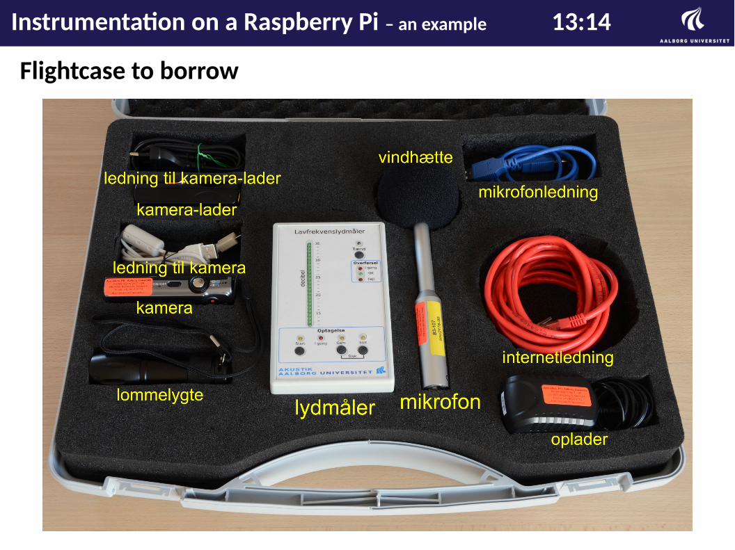
Flightcase to borrow
Instrumentation on a Raspberry Pi – an example 13:14
The end
Instrumentation on a Raspberry Pi – an example 14:14