Embed Size (px)
Citation preview
ELECTROMATEToll Free Phone (877) SERVO98
Toll Free Fax (877) SERV099www.electromate.com
Sold & Serviced By:
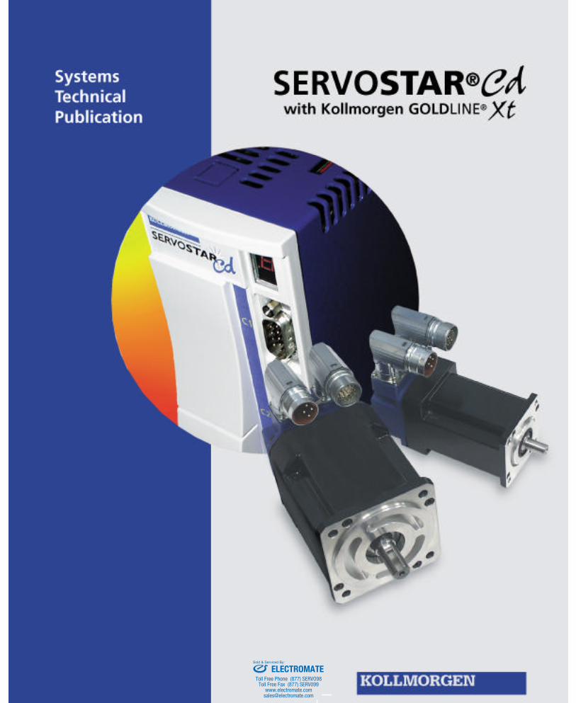
SERVOSTAR CD
KOLLMORGEN • Radford, Virginia • 1-800-77 SERVO
INTRODUCTION
2
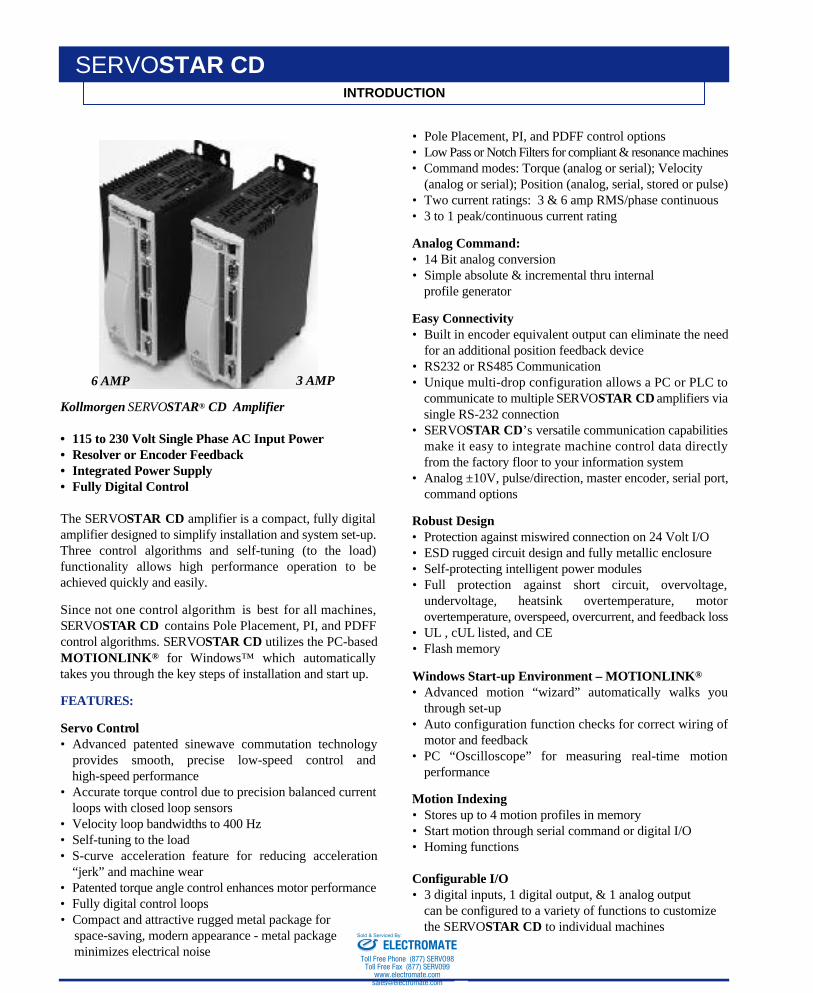
Kollmorgen S E RVOS TA R® C D A m p l i f i e r
• 115 to 230 Volt Single Phase AC Input Power• R e s o l v e r o r E n c o d e r F e e d b a c k• Integrated Power S u p p l y• Fully Digital Contro l
The S E RV OS TA R C D amplifier is a compact, fully digitalamplifier designed to simplify installation and system set-up.Three control algorithms and self-tuning (to the load)functionality allows high performance operation to beachieved quickly and easily.
Since not one control algorithm is best for all machines,S E RV OS TAR CD contains Pole Placement, PI, and PDFFcontrol algorithms. S E RV OS TAR CD utilizes the PC-basedM O T I O N L I N K® for Windows™ which automaticallytakes you through the key steps of installation and start up.
F E AT U R E S :
Servo Contro l• Advanced patented sinewave commutation technology
provides smooth, precise low-speed control andhigh-speed performance
• Accurate torque control due to precision balanced currentloops with closed loop sensors
• Velocity loop bandwidths to 400 Hz • Self-tuning to the load• S-curve acceleration feature for reducing acceleration
“jerk” and machine wear• Patented torque angle control enhances motor performance• Fully digital control loops• Compact and attractive rugged metal package for
space-saving, modern appearance - metal packageminimizes electrical noise
• Pole Placement, PI, and PDFF control options• Low Pass or Notch Filters for compliant & resonance machines• Command modes: Torque (analog or serial); Velocity
(analog or serial); Position (analog, serial, stored or pulse)• Two current ratings: 3 & 6 amp RMS/phase continuous• 3 to 1 peak/continuous current rating
Analog Command:• 14 Bit analog conversion• Simple absolute & incremental thru internal
profile generator
Easy Connectivity• Built in encoder equivalent output can eliminate the need
for an additional position feedback device• RS232 or RS485 Communication• Unique multi-drop configuration allows a PC or PLC to
communicate to multiple S E RV OS TAR CD amplifiers viasingle RS-232 connection
• S E RV OS TAR CD’s versatile communication capabilitiesmake it easy to integrate machine control data directlyfrom the factory floor to your information system
• Analog ±10V, pulse/direction, master encoder, serial port,command options
Robust Design• Protection against miswired connection on 24 Volt I/O• ESD rugged circuit design and fully metallic enclosure• Self-protecting intelligent power modules• Full protection against short circuit, overvoltage,
undervoltage, heatsink overtemperature, motorovertemperature, overspeed, overcurrent, and feedback loss
• U L , cUL listed, and CE • Flash memory
Windows Start-up Environment – MOTIONLINK®
• Advanced motion “wizard” automatically walks youthrough set-up
• Auto configuration function checks for correct wiring ofmotor and feedback
• PC “Oscilloscope” for measuring real-time motionp e r f o r m a n c e
Motion Indexing• Stores up to 4 motion profiles in memory• Start motion through serial command or digital I/O• Homing functions
Configurable I/O • 3 digital inputs, 1 digital output, & 1 analog output
can be configured to a variety of functions to customizethe SERV OS TAR CD to individual machines
6 AMP 3 AMP
ELECTROMATEToll Free Phone (877) SERVO98
Toll Free Fax (877) SERV099www.electromate.com
Sold & Serviced By:
KOLLMORGEN • Radford, Virginia • 1-800-77 SERVO 3
AUTO SET-UP
SERVOSTAR CD MOTIONLINK
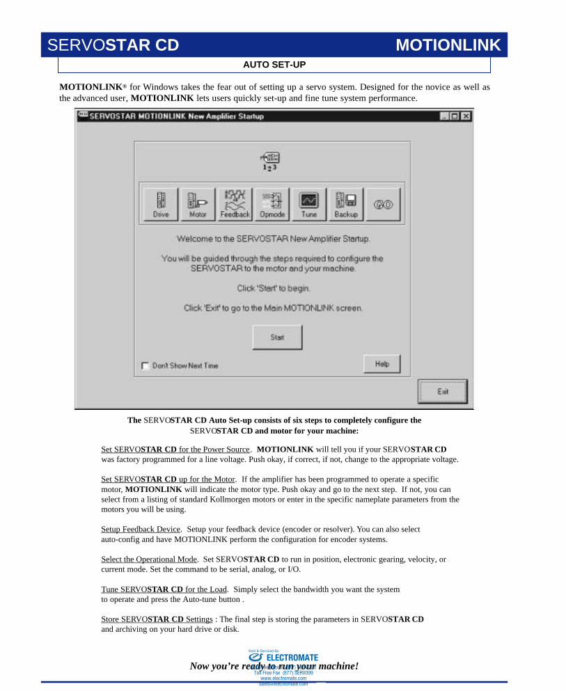
MOTIONLINK® for Windows takes the fear out of setting up a servo system. Designed for the novice as well asthe advanced user, MOTIONLINK lets users quickly set-up and fine tune system performance.
Set SERVOSTAR CD for the Power Source. MOTIONLINK will tell you if your SERVOSTAR CDwas factory programmed for a line voltage. Push okay, if correct, if not, change to the appropriate voltage.
Set SERVOSTAR CD up for the Motor. If the amplifier has been programmed to operate a specificmotor, MOTIONLINK will indicate the motor type. Push okay and go to the next step. If not, you canselect from a listing of standard Kollmorgen motors or enter in the specific nameplate parameters from themotors you will be using.
Setup Feedback Device. Setup your feedback device (encoder or resolver). You can also selectauto-config and have MOTIONLINK perform the configuration for encoder systems.
Select the Operational Mode. Set SERVOSTAR CD to run in position, electronic gearing, velocity, orcurrent mode. Set the command to be serial, analog, or I/O.
Tune SERVOSTAR CD for the Load. Simply select the bandwidth you want the systemto operate and press the Auto-tune button .
Store SERVOSTAR CD Settings : The final step is storing the parameters in SERVOSTAR CDand archiving on your hard drive or disk.
The SERVOSTAR CD Auto Set-up consists of six steps to completely configure theSERVOSTAR CD and motor for your machine:
Now you’re ready to run your machine!ELECTROMATE
Toll Free Phone (877) SERVO98Toll Free Fax (877) SERV099
Sold & Serviced By:
KOLLMORGEN • Radford, Virginia • 1-800-77 SERVO4
ADDITIONAL FUNCTIONS
MOTIONLINK SERVOSTAR CD
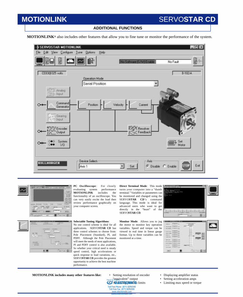
MOTIONLINK® also includes other features that allow you to fine tune or monitor the performance of the system.
MOTIONLINK includes many other features like: • Setting resolution of encoder“equivalent” output
• Activating position limits
• Displaying amplifier status• Setting acceleration amps• Limiting max speed or torque
PC Oscilloscope : For closelyevaluating system performanceM O T I O N L I N K includes thefunctionality of an oscilloscope. Youcan very easily excite the load thenreview performance graphically onyour computer screen.
Selectable Tuning Algorithms:No one control scheme is ideal for allapplications. SERVOSTAR CD hasthree control schemes to choose from:Pole Placement (Standard), PI, andPDFF. Although the Pole Placementwill meet the needs of most applications,PI and PDFF control is also available.So whether your critical need is steadyspeed control, high accelerations orquick response to load variations, etc.,SERVOSTAR CD provides the greatestopportunity to achieve the best machineperformance.
Direct Terminal Mode: This modeturns your computer into a “dumbterminal.” Variables or parameters canbe monitored and changed using theS E RV OS TAR CD ’s commandlanguage. This mode is ideal foradvanced users who want to getdirectly in the “heart” of theSERVOSTAR CD.
Monitor Mode: Allows you to jogthe motor to monitor key operationvariables. Speed and torque can beviewed in real time in linear gaugeformat. Up to three variables can bemonitored at a time.
ELECTROMATEToll Free Phone (877) SERVO98
Toll Free Fax (877) SERV099www.electromate.com
Sold & Serviced By:
KOLLMORGEN • Radford, Virginia • 1-800-77 SERVO 5
PROGRAMMABLE FUNCTIONS
MOTIONLINK
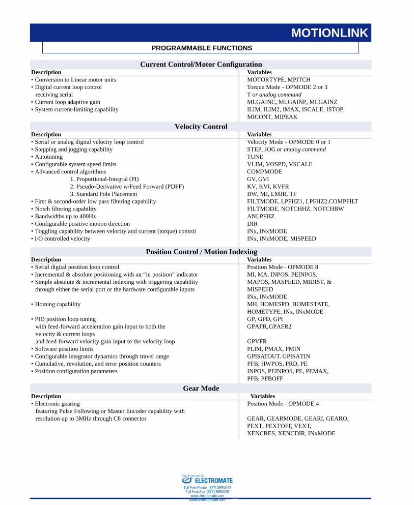
Current Control/Motor ConfigurationDescription Variables• Conversion to Linear motor units MOTORTYPE, MPITCH• Digital current loop control Torque Mode - OPMODE 2 or 3
receiving serial T or analog command• Current loop adaptive gain MLGAINC, MLGAINP, MLGAINZ• System current-limiting capability ILIM, ILIM2, IMAX, ISCALE, ISTOP,
MICONT, MIPEAK
Velocity ControlDescription Variables• Serial or analog digital velocity loop control Velocity Mode - OPMODE 0 or 1• Stepping and jogging capability STEP, JOG or analog command• Autotuning TUNE• Configurable system speed limits VLIM, VOSPD, VSCALE• Advanced control algorithms COMPMODE
1. Proportional-Integral (PI) GV, GVI2. Pseudo-Derivative w/Feed Forward (PDFF) KV, KVI, KVFR3. Standard Pole Placement BW, MJ, LMJR, TF
• First & second-order low pass filtering capability FILTMODE, LPFHZ1, LPFHZ2,COMPFILT• Notch filtering capability FILTMODE, NOTCHHZ, NOTCHBW• Bandwidths up to 400Hz ANLPFHZ• Configurable positive motion direction DIR• Toggling capability between velocity and current (torque) control INx, INxMODE • I/O controlled velocity INx, INxMODE, MISPEED
Position Control / Motion IndexingDescription Variables• Serial digital position loop control Position Mode - OPMODE 8• Incremental & absolute positioning with an “in position” indicator MI, MA, INPOS, PEINPOS,• Simple absolute & incremental indexing with triggering capability MAPOS, MASPEED, MIDIST, &
through either the serial port or the hardware configurable inputs MISPEEDINx, INxMODE
• Homing capability MH, HOMESPD, HOMESTATE,HOMETYPE, INx, INxMODE
• PID position loop tuning GP, GPD, GPIwith feed-forward acceleration gain input to both the GPAFR, GPAFR2velocity & current loopsand feed-forward velocity gain input to the velocity loop GPVFR
• Software position limits PLIM, PMAX, PMIN• Configurable integrator dynamics through travel range GPISATOUT, GPISATIN• Cumulative, revolution, and error position counters PFB, HWPOS, PRD, PE• Position configuration parameters INPOS, PEINPOS, PE, PEMAX,
PFB, PFBOFF
Gear ModeDescription Variables• Electronic gearing Position Mode - OPMODE 4
featuring Pulse Following or Master Encoder capability with resolution up to 3MHz through C8 connector GEAR, GEARMODE, GEARI, GEARO,
PEXT, PEXTOFF, VEXT,XENCRES, XENCDIR, INxMODE
ELECTROMATEToll Free Phone (877) SERVO98
Toll Free Fax (877) SERV099www.electromate.com
Sold & Serviced By:
KOLLMORGEN • Radford, Virginia • 1-800-77 SERVO6
PROGRAMMABLE FUNCTIONS
MOTIONLINK
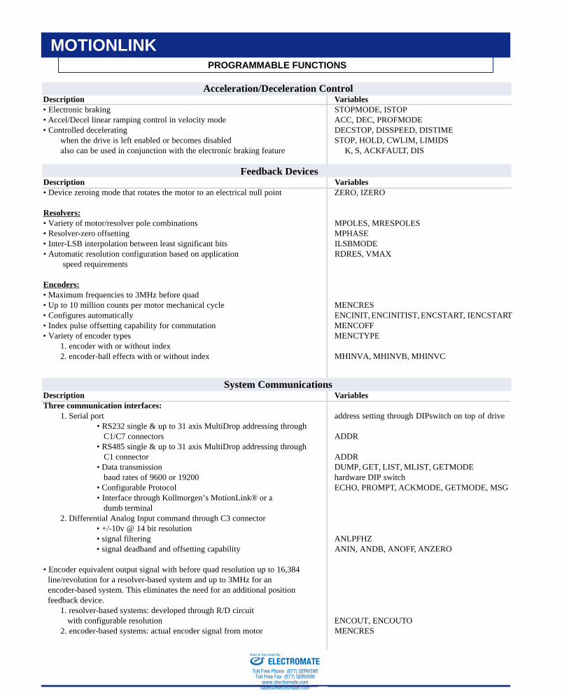
Acceleration/Deceleration ControlDescription Variables• Electronic braking STOPMODE, ISTOP• Accel/Decel linear ramping control in velocity mode ACC, DEC, PROFMODE• Controlled decelerating DECSTOP, DISSPEED, DISTIME
when the drive is left enabled or becomes disabled STOP, HOLD, CWLIM, LIMIDSalso can be used in conjunction with the electronic braking feature K, S, ACKFAULT, DIS
Feedback DevicesDescription Variables• Device zeroing mode that rotates the motor to an electrical null point ZERO, IZERO
Resolvers:• Variety of motor/resolver pole combinations MPOLES, MRESPOLES• Resolver-zero offsetting MPHASE• Inter-LSB interpolation between least significant bits ILSBMODE• Automatic resolution configuration based on application RDRES, VMAX
speed requirements
Encoders:• Maximum frequencies to 3MHz before quad• Up to 10 million counts per motor mechanical cycle MENCRES• Configures automatically ENCINIT, ENCINITIST, ENCSTART, IENCSTART• Index pulse offsetting capability for commutation MENCOFF• Variety of encoder types MENCTYPE
1. encoder with or without index2. encoder-hall effects with or without index MHINVA, MHINVB, MHINVC
System CommunicationsDescription VariablesThree communication interfaces:
1. Serial port address setting through DIPswitch on top of drive• RS232 single & up to 31 axis MultiDrop addressing through
C1/C7 connectors ADDR• RS485 single & up to 31 axis MultiDrop addressing through
C1 connector ADDR• Data transmission DUMP, GET, LIST, MLIST, GETMODE
baud rates of 9600 or 19200 hardware DIP switch• Configurable Protocol ECHO, PROMPT, ACKMODE, GETMODE, MSG• Interface through Kollmorgen’s MotionLink® or a
dumb terminal2. Differential Analog Input command through C3 connector
• +/-10v @ 14 bit resolution• signal filtering ANLPFHZ• signal deadband and offsetting capability ANIN, ANDB, ANOFF, ANZERO
• Encoder equivalent output signal with before quad resolution up to 16,384 line/revolution for a resolver-based system and up to 3MHz for an encoder-based system. This eliminates the need for an additional positionfeedback device.
1. resolver-based systems: developed through R/D circuitwith configurable resolution ENCOUT, ENCOUTO
2. encoder-based systems: actual encoder signal from motor MENCRES
ELECTROMATEToll Free Phone (877) SERVO98
Toll Free Fax (877) SERV099www.electromate.com
Sold & Serviced By:
KOLLMORGEN • Radford, Virginia • 1-800-77 SERVO 7
PROGRAMMABLE FUNCTIONS
MOTIONLINK
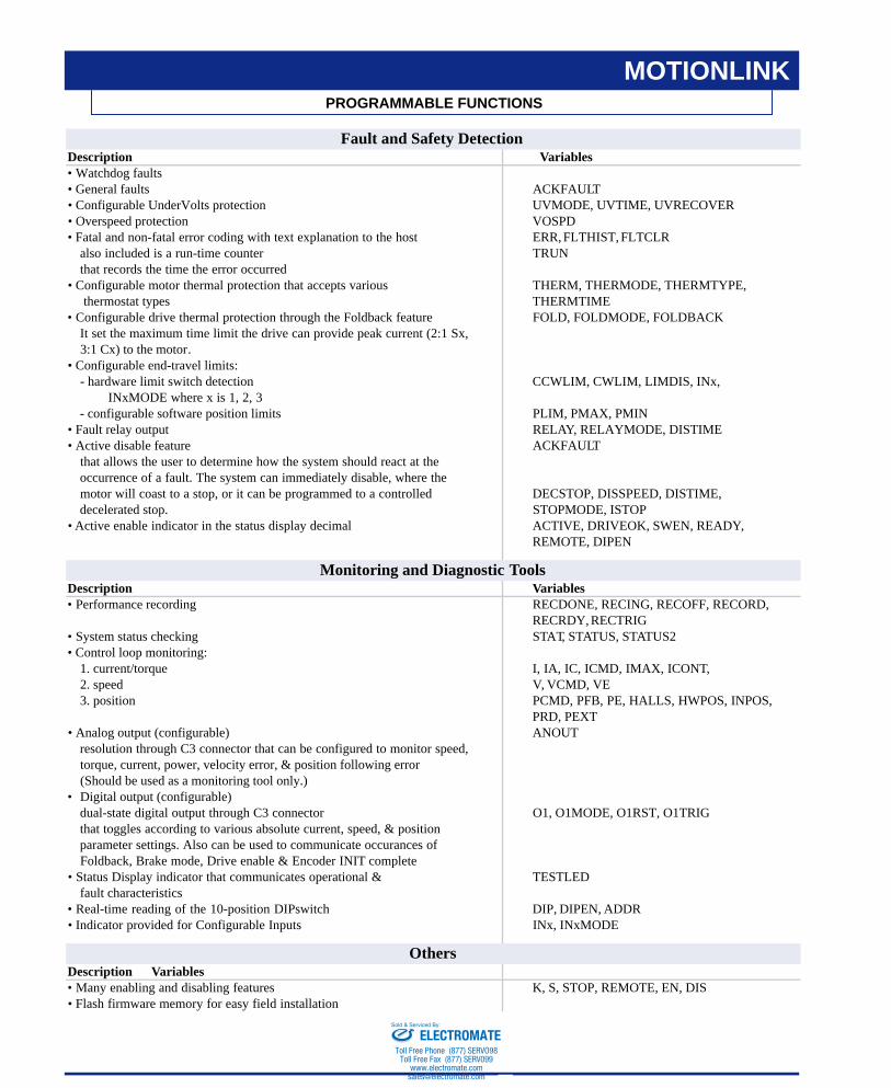
Fault and Safety DetectionDescription Variables• Watchdog faults• General faults ACKFAULT• Configurable UnderVolts protection UVMODE, UVTIME, UVRECOVER• Overspeed protection VOSPD• Fatal and non-fatal error coding with text explanation to the host ERR, FLTHIST, FLTCLR
also included is a run-time counter TRUN that records the time the error occurred
• Configurable motor thermal protection that accepts various THERM, THERMODE, THERMTYPE,thermostat types THERMTIME
• Configurable drive thermal protection through the Foldback feature FOLD, FOLDMODE, FOLDBACKIt set the maximum time limit the drive can provide peak current (2:1 Sx,3:1 Cx) to the motor.
• Configurable end-travel limits:- hardware limit switch detection CCWLIM, CWLIM, LIMDIS, INx,
INxMODE where x is 1, 2, 3- configurable software position limits PLIM, PMAX, PMIN
• Fault relay output RELAY, RELAYMODE, DISTIME• Active disable feature ACKFAULT
that allows the user to determine how the system should react at the occurrence of a fault. The system can immediately disable, where themotor will coast to a stop, or it can be programmed to a controlled DECSTOP, DISSPEED, DISTIME,decelerated stop. STOPMODE, ISTOP
• Active enable indicator in the status display decimal ACTIVE, DRIVEOK, SWEN, READY,REMOTE, DIPEN
Monitoring and Diagnostic ToolsDescription Variables• Performance recording RECDONE, RECING, RECOFF, RECORD,
RECRDY, RECTRIG• System status checking STAT, STATUS, STATUS2• Control loop monitoring:
1. current/torque I, IA, IC, ICMD, IMAX, ICONT,2. speed V, VCMD, VE3. position PCMD, PFB, PE, HALLS, HWPOS, INPOS,
PRD, PEXT• Analog output (configurable) ANOUT
resolution through C3 connector that can be configured to monitor speed,torque, current, power, velocity error, & position following error(Should be used as a monitoring tool only.)
• Digital output (configurable)dual-state digital output through C3 connector O1, O1MODE, O1RST, O1TRIGthat toggles according to various absolute current, speed, & positionparameter settings. Also can be used to communicate occurances of Foldback, Brake mode, Drive enable & Encoder INIT complete
• Status Display indicator that communicates operational & TESTLEDfault characteristics
• Real-time reading of the 10-position DIPswitch DIP, DIPEN, ADDR• Indicator provided for Configurable Inputs INx, INxMODE
OthersDescription Variables• Many enabling and disabling features K, S, STOP, REMOTE, EN, DIS• Flash firmware memory for easy field installation
ELECTROMATEToll Free Phone (877) SERVO98
Toll Free Fax (877) SERV099www.electromate.com
Sold & Serviced By:
SERVOSTAR CD
KOLLMORGEN • Radford, Virginia • 1-800-77 SERVO8
AMPLIFIER SPECIFICATIONS
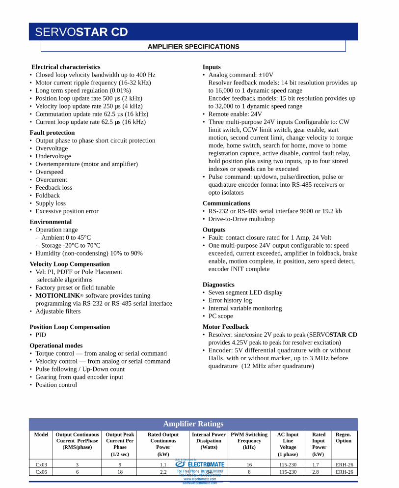
Electrical characteristics• Closed loop velocity bandwidth up to 400 Hz• Motor current ripple frequency (16-32 kHz)• Long term speed regulation (0.01%)• Position loop update rate 500 µs (2 kHz)• Velocity loop update rate 250 µs (4 kHz)• Commutation update rate 62.5 µs (16 kHz) • Current loop update rate 62.5 µs (16 kHz)
Fault protection• Output phase to phase short circuit protection• Overvoltage• Undervoltage• Overtemperature (motor and amplifier)• Overspeed• Overcurrent• Feedback loss• Foldback• Supply loss• Excessive position error
Environmental• Operation range
- Ambient 0 to 45°C- Storage -20°C to 70°C
• Humidity (non-condensing) 10% to 90%
Velocity Loop Compensation• Vel: PI, PDFF or Pole Placement
selectable algorithms• Factory preset or field tunable• MOTIONLINK® software provides tuning
programming via RS-232 or RS-485 serial interface• Adjustable filters
Position Loop Compensation• PID
Operational modes• Torque control — from analog or serial command• Velocity control — from analog or serial command• Pulse following / Up-Down count• Gearing from quad encoder input• Position control
Inputs• Analog command: ±10V
Resolver feedback models: 14 bit resolution provides upto 16,000 to 1 dynamic speed rangeEncoder feedback models: 15 bit resolution provides upto 32,000 to 1 dynamic speed range
• Remote enable: 24V• Three multi-purpose 24V inputs Configurable to: CW
limit switch, CCW limit switch, gear enable, startmotion, second current limit, change velocity to torquemode, home switch, search for home, move to homeregistration capture, active disable, control fault relay,hold position plus using two inputs, up to four storedindexes or speeds can be executed
• Pulse command: up/down, pulse/direction, pulse orquadrature encoder format into RS-485 receivers oropto isolators
Communications• RS-232 or RS-48S serial interface 9600 or 19.2 kb• Drive-to-Drive multidrop
Outputs• Fault: contact closure rated for 1 Amp, 24 Volt• One multi-purpose 24V output configurable to: speed
exceeded, current exceeded, amplifier in foldback, brakeenable, motion complete, in position, zero speed detect,encoder INIT complete
Diagnostics• Seven segment LED display• Error history log• Internal variable monitoring• PC scope
Motor Feedback• Resolver: sine/cosine 2V peak to peak (SERV OS TAR CD
provides 4.25V peak to peak for resolver excitation)• Encoder: 5V d i fferential quadrature with or without
Halls, with or without marker, up to 3 MHz beforequadrature (12 MHz after quadrature)
Model Output Continuous Output Peak Rated Output Internal Power PWM Switching AC Input Rated Regen.Current PerPhase Current Per Continuous Dissipation Frequency Line Input Option
(RMS/phase) Phase Power (Watts) (kHz) Voltage Power(1/2 sec) (kW) (1 phase) (kW)
Cx03 3 9 1.1 37 16 115-230 1.7 ERH-26Cx06 6 18 2.2 84 8 115-230 2.8 ERH-26
Amplifier Ratings
ELECTROMATEToll Free Phone (877) SERVO98
Toll Free Fax (877) SERV099www.electromate.com
Sold & Serviced By:
KOLLMORGEN • Radford, Virginia • 1-800-77 SERVO 9
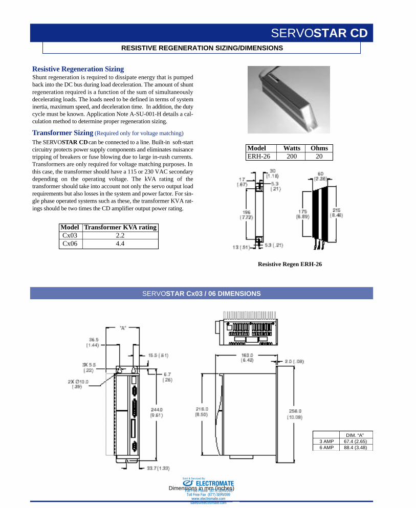
Resistive Regeneration SizingShunt regeneration is required to dissipate energy that is pumpedback into the DC bus during load deceleration. The amount of shuntregeneration required is a function of the sum of simultaneouslydecelerating loads. The loads need to be defined in terms of systeminertia, maximum speed, and deceleration time. In addition, the dutycycle must be known. Application Note A-SU-001-H details a cal-culation method to determine proper regeneration sizing.
Tr a n s f o r m e r Sizing (Required only for voltage matching)
The SERV OS TAR CDcan be connected to a line. Built-in soft-startcircuitry protects power supply components and eliminates nuisancetripping of breakers or fuse blowing due to large in-rush currents.Transformers are only required for voltage matching purposes. Inthis case, the transformer should have a 115 or 230 VAC secondarydepending on the operating voltage. The kVA rating of thetransformer should take into account not only the servo output loadrequirements but also losses in the system and power factor. For sin-gle phase operated systems such as these, the transformer KVA r a t-ings should be two times the CD amplifier output power rating.
RESISTIVE REGENERATION SIZING/DIMENSIONS
SERVOSTAR CD
SERVOSTAR Cx03 / 06 DIMENSIONS
Dimensions in mm (inches)
DIM. “A”3 AMP 67.4 (2.65)6 AMP 88.4 (3.48)
Resistive Regen ERH-26
Model Transformer KVA ratingCx03 2.2Cx06 4.4
Model Watts OhmsERH-26 200 20
ELECTROMATEToll Free Phone (877) SERVO98
Toll Free Fax (877) SERV099www.electromate.com
Sold & Serviced By:
KOLLMORGEN • Radford, Virginia • 1-800-77 SERVO10
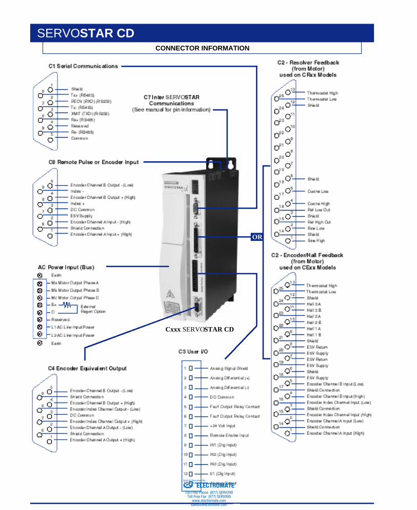
CONNECTOR INFORMATION
SERVOSTAR CD
Cxxx SERVOSTAR CD
OR
ELECTROMATEToll Free Phone (877) SERVO98
Toll Free Fax (877) SERV099www.electromate.com
Sold & Serviced By:
KOLLMORGEN • Radford, Virginia • 1-800-77 SERVO 11
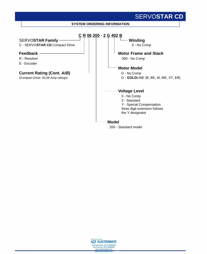
SYSTEM ORDERING INFORMATION
SERVOSTAR CD
C R 06 200 - 2 G 402 BSERVOSTAR Family WindingC - SERVOSTAR CD Compact Drive 0 - No Comp
Feedback Motor Frame and StackR - Resolver 000 - No Comp
E - EncoderMotor Model
Current Rating (Cont. A/Ø) O - No Comp(Compact Drive: 03,06 Amp ratings) G - GOLDLINE (B, BE, M, ME, XT, EB)
Voltage Level0 - No Comp2 - StandardY - Special Compensationthree digit extension followsthe Y designator
Model200 - Standard model
ELECTROMATEToll Free Phone (877) SERVO98
Toll Free Fax (877) SERV099www.electromate.com
Sold & Serviced By:
KOLLMORGEN • Radford, Virginia • 1-800-77 SERVO12
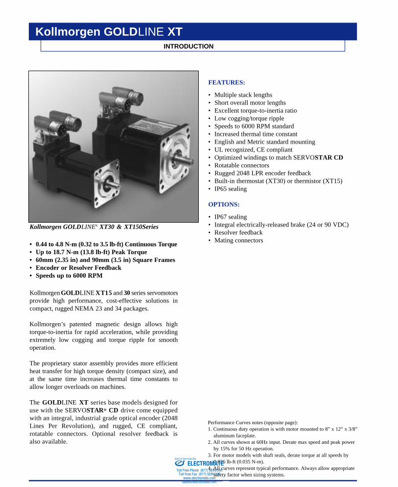
Kollmorgen GOLDLINE® XT30 & XT150Series
• 0.44 to 4.8 N-m (0.32 to 3.5 lb-ft) Continuous To rq u e• Up to 18.7 N-m (13.8 lb-ft) Peak Torque• 60mm (2.35 in) and 90mm (3.5 in) Square Frames• Encoder or Resolver Feedback• Speeds up to 6000 RPM
K o l l m o rgen G O L DLINE X T1 5 and 3 0 series servomotorsprovide high performance, cost-effective solutions incompact, rugged NEMA 23 and 34 packages.
K o l l m o rg e n ’s patented magnetic design allows hightorque-to-inertia for rapid acceleration, while providingextremely low cogging and torque ripple for smoothoperation.
The proprietary stator assembly provides more efficientheat transfer for high torque density (compact size), andat the same time increases thermal time constants toallow longer overloads on machines.
The G O L DLINE X T series base models designed foruse with the SERV OS TA R® C D drive come equippedwith an integral, industrial grade optical encoder (2048Lines Per Revolution), and rugged, CE compliant,rotatable connectors. Optional resolver feedback isalso available.
FEATURES:
• Multiple stack lengths• Short overall motor lengths• Excellent torque-to-inertia ratio• Low cogging/torque ripple• Speeds to 6000 RPM standard• Increased thermal time constant• English and Metric standard mounting• UL recognized, CE compliant• Optimized windings to match SERVOSTAR CD• Rotatable connectors• Rugged 2048 LPR encoder feedback• Built-in thermostat (XT30) or thermistor (XT15)• IP65 sealing
OPTIONS:
• IP67 sealing• Integral electrically-released brake (24 or 90 VDC)• Resolver feedback• Mating connectors
INTRODUCTION
Kollmorgen GOLDLINE XT
Performance Curves notes (opposite page):1. Continuous duty operation is with motor mounted to 8” x 12” x 3/8”
aluminum faceplate.2. All curves shown at 60Hz input. Derate max speed and peak power
by 15% for 50 Hz operation.3. For motor models with shaft seals, derate torque at all speeds by
0.026 lb-ft (0.035 N-m).4. All curves represent typical performance. Always allow appropriate
safety factor when sizing systems.
ELECTROMATEToll Free Phone (877) SERVO98
Toll Free Fax (877) SERV099www.electromate.com
Sold & Serviced By:
Kollmorgen GOLDLINE XT and SERVOSTAR CD
13KOLLMORGEN • Radford, Virginia • 1-800-77 SERVO
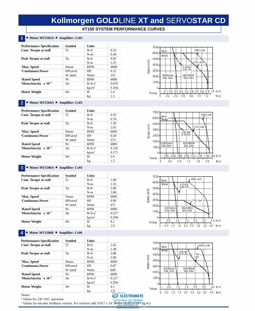
XT150 SYSTEM PERFORMANCE CURVES
4 Motor MT1506B Amplifier: Cx06
Performance Specification Symbol UnitsCont. Torque at stall Tc lb-ft 1.02
N-m 1.38Peak Torque at stall Tp lb-ft 2.88
N-m 3.901Max. Speed Nmax RPM 60001Continuous Power HPrated HP 0.87
W rated Watts 6491Rated Speed Nr RPM 60002MotorInertia x 10-4 Jm lb-ft-s2 0.217
kg-m2 0.294Motor Weight Wt lb 4.1
kg 1.9Notes: 1 Values for 230 VAC operation.2 Values for encoder feedback version. For resolver add: 0.017 x 10⁻⁴ lb-ft-s2 (0.023 x 10 -4 kg-m2)
Motor MT1502A Amplifier: Cx03
Performance Specification Symbol UnitsCont. Torque at stall Tc lb-ft 0.32
N-m 0.44Peak Torque at stall Tp lb-ft 0.92
N-m 1.251Max. Speed Nmax RPM 60001Continuous Power HPrated HP 0.31
W rated Watts 2311Rated Speed Nr RPM 60002MotorInertia x 10-4 Jm lb-ft-s2 0.076
kg-m2 0.104Motor Weight Wt lb 2.4
kg 1.1
Motor MT1504A Amplifier: Cx03
Performance Specification Symbol UnitsCont. Torque at stall Tc lb-ft 0.55
N-m 0.74Peak Torque at stall Tp lb-ft 1.50
N-m 2.031Max. Speed Nmax RPM 60001Continuous Power HPrated HP 0.50
W rated Watts 3731Rated Speed Nr RPM 60002MotorInertia x 10-4 Jm lb-ft-s2 0.126
kg-m2 0.171Motor Weight Wt lb 2.9
kg 1.3
Motor MT1506A Amplifier: Cx03
Performance Specification Symbol UnitsCont. Torque at stall Tc lb-ft 1.00
N-m 1.35Peak Torque at stall Tp lb-ft 2.80
N-m 3.801Max. Speed Nmax RPM 60001Continuous Power HPrated HP 0.90
W rated Watts 6711Rated Speed Nr RPM 60002MotorInertia x 10-4 Jm lb-ft-s2 0.217
kg-m2 0.294Motor Weight Wt lb 4.1
kg 1.9
1
2
3
ELECTROMATEToll Free Phone (877) SERVO98
Toll Free Fax (877) SERV099www.electromate.com
Sold & Serviced By:
KOLLMORGEN • Radford, Virginia • 1-800-77 SERVO14
Kollmorgen GOLDLINE XT and SERVOSTAR CDXT30 SYSTEM PERFORMANCE CURVES
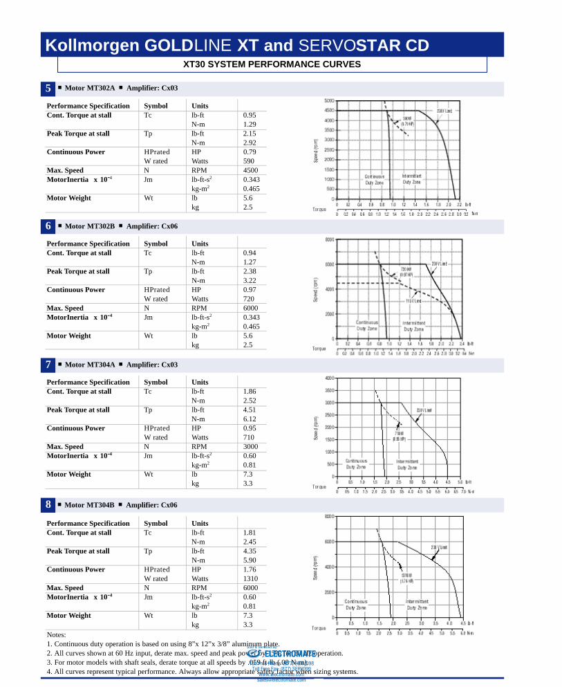
8 Motor MT304B Amplifier: Cx06
Performance Specification Symbol UnitsCont. Torque at stall Tc lb-ft 1.81
N-m 2.45Peak Torque at stall Tp lb-ft 4.35
N-m 5.90Continuous Power HPrated HP 1.76
W rated Watts 1310Max. Speed N RPM 6000MotorInertia x 10-4 Jm lb-ft-s2 0.60
kg-m2 0.81Motor Weight Wt lb 7.3
kg 3.3Notes: 1. Continuous duty operation is based on using 8”x 12”x 3/8” aluminum plate.2. All curves shown at 60 Hz input, derate max. speed and peak power by 15% for 50 Hz operation.3. For motor models with shaft seals, derate torque at all speeds by .059 ft-lb (.08 N-m).4. All curves represent typical performance. Always allow appropriate safety factor when sizing systems.
Motor MT302A Amplifier: Cx03
Performance Specification Symbol UnitsCont. Torque at stall Tc lb-ft 0.95
N-m 1.29Peak Torque at stall Tp lb-ft 2.15
N-m 2.92Continuous Power HPrated HP 0.79
W rated Watts 590Max. Speed N RPM 4500MotorInertia x 10-4 Jm lb-ft-s2 0.343
kg-m2 0.465Motor Weight Wt lb 5.6
kg 2.5
Motor MT302B Amplifier: Cx06
Performance Specification Symbol UnitsCont. Torque at stall Tc lb-ft 0.94
N-m 1.27Peak Torque at stall Tp lb-ft 2.38
N-m 3.22Continuous Power HPrated HP 0.97
W rated Watts 720Max. Speed N RPM 6000MotorInertia x 10-4 Jm lb-ft-s2 0.343
kg-m2 0.465Motor Weight Wt lb 5.6
kg 2.5
Motor MT304A Amplifier: Cx03
Performance Specification Symbol UnitsCont. Torque at stall Tc lb-ft 1.86
N-m 2.52Peak Torque at stall Tp lb-ft 4.51
N-m 6.12Continuous Power HPrated HP 0.95
W rated Watts 710Max. Speed N RPM 3000MotorInertia x 10-4 Jm lb-ft-s2 0.60
kg-m2 0.81Motor Weight Wt lb 7.3
kg 3.3
5
6
7
ELECTROMATEToll Free Phone (877) SERVO98
Toll Free Fax (877) SERV099www.electromate.com
Sold & Serviced By:
KOLLMORGEN • Radford, Virginia • 1-800-77 SERVO 15
Kollmorgen GOLDLINE XT and SERVOSTAR CDXT30 SYSTEM PERFORMANCE CURVES
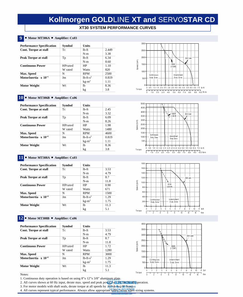
12 Motor MT308B Amplifier: Cx06
Performance Specification Symbol UnitsCont. Torque at stall Tc lb-ft 3.53
N-m 4.79Peak Torque at stall Tp lb-ft 8.7
N-m 11.8Continuous Power HPrated HP 1.72
W rated Watts 1280Max. Speed N RPM 3000MotorInertia x 10-4 Jm lb-ft-s2 1.29
kg-m2 1.75Motor Weight Wt lb 11.3
kg 5.1Notes: 1. Continuous duty operation is based on using 8”x 12”x 3/8” aluminum plate.2. All curves shown at 60 Hz input, derate max. speed and peak power by 15% for 50 Hz operation.3. For motor models with shaft seals, derate torque at all speeds by .059 ft-lb (.08 N-m).4. All curves represent typical performance. Always allow appropriate safety factor when sizing systems.
Motor MT306A Amplifier: Cx03
Performance Specification Symbol UnitsCont. Torque at stall Tc lb-ft 2.449
N-m 3.38Peak Torque at stall Tp lb-ft 6.34
N-m 8.60Continuous Power HPrated HP 1.10
W rated Watts 820Max. Speed N RPM 2500MotorInertia x 10-4 Jm lb-ft-s2 0.819
kg-m2 1.11Motor Weight Wt lb 8.36
kg 3.8
Motor MT306B Amplifier: Cx06
Performance Specification Symbol UnitsCont. Torque at stall Tc lb-ft 2.45
N-m 3.32Peak Torque at stall Tp lb-ft 6.09
N-m 8.26Continuous Power HPrated HP 1.98
W rated Watts 1480Max. Speed N RPM 4600MotorInertia x 10-4 Jm lb-ft-s2 0.819
kg-m2 1.11Motor Weight Wt lb 8.36
kg 3.8
Motor MT308A Amplifier: Cx03
Performance Specification Symbol UnitsCont. Torque at stall Tc lb-ft 3.53
N-m 4.79Peak Torque at stall Tp lb-ft 8.7
N-m 11.8Continuous Power HPrated HP 0.90
W rated Watts 671Max. Speed N RPM 1500MotorInertia x 10-4 Jm lb-ft-s2 1.29
kg-m2 1.75Motor Weight Wt lb 11.3
kg 5.1
9
10
11
ELECTROMATEToll Free Phone (877) SERVO98
Toll Free Fax (877) SERV099www.electromate.com
Sold & Serviced By:
Kollmorgen GOLDLINE XT
KOLLMORGEN • Radford, Virginia • 1-800-77 SERVO
DIMENSIONS
16
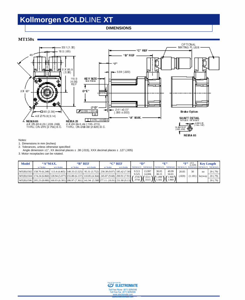
MT150x
Notes:1. Dimensions in mm (inches)2. Tolerances, unless otherwise specified:
Angle dimension ±1°, XX decimal places ± .38 (.015), XXX decimal places ± .127 (.005)3. Motor receptacles can be rotated.
Model “A”MAX. “B” REF “C” REF “D” “E” “F” Key Lengthw/ brake w/o brake w/ brake w/o brake w/ brake w/o brake NEMA23 NEMA65 NEMA23 NEMA65 NEMA23 NEMA65 NEMA23 NEMA65
MT(B)1502 158.70 (6.248) 113.4 (4.465) 140.33 (5.525) 95.31 (3.752) 230.38 (9.07) 185.42 (7.30) 20.83 30 no 20 (.79)
MT(B)1504 174.24 (6.860) 128.94 (5.077) 155.88 (6.137) 110.85 (4.364) 245.87 (9.68) 200.91 (7.91) (.820) (1.181) keyway 20 (.79)
MT(B)1506 205.23 (8.080) 160.03 (6.301) 186.97 (7.361) 141.94 (5.588)277.11 (10.91) 231.90 (9.13) 20 (.79)
±0.5(±.020)
( )( ) ( ) ( )9.513 13.997 38.05 49.999.525 14.006 38.15 50.01.3745 .5511 1.498 1.968.3750 .5515 1.502 1.969
ELECTROMATEToll Free Phone (877) SERVO98
Toll Free Fax (877) SERV099www.electromate.com
Sold & Serviced By:
Kollmorgen GOLDLINE XT
KOLLMORGEN • Radford, Virginia • 1-800-77 SERVO
DIMENSIONS
17
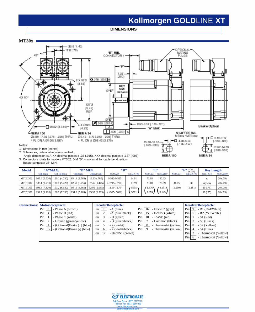
Connections: MotorReceptacle: EncoderReceptacle: ResolverReceptacle:Pin 3 - Phase A (brown) Pin 1 -A (blue) Pin 16 - Hbc=S2 (gray) Pin 9 - R1 (Red/White)Pin 4 - Phase B (red) Pin 2 -A (blue/black) Pin 15 - Hca=S3 (white) Pin 5 - R2 (Yel/White)Pin 1 - Phase C (white) Pin 3 - B (green) Pin 10 - +5Vdc (red) Pin 7 - S1 (Red)Pin 2 - Ground (green/yellow) Pin 4 - B (green/black) Pin 7 - Common (black) Pin 3 - S3 (Black)Pin A - (Optional)Brake (+) (blue) Pin 5 - Z (violet) Pin 8 - Thermostat (yellow) Pin 8 - S2 (Yellow)Pin B - (Optional)Brake (-) (blue) Pin 6 - Z (violet/black) Pin 9 - Thermostat (yellow) Pin 4 - S4 (Blue)
Pin 17 - Hab=S1 (brown) Pin 2 - Thermostat (Yellow)Pin 6 - Thermostat (Yellow)
MT30x
Notes:1. Dimensions in mm (inches)2. Tolerances, unless otherwise specified:
Angle dimension ±1°, XX decimal places ± .38 (.015), XXX decimal places ± .127 (.005)3. Connectors rotate for models MT302. DIM “B” is too small for cable bend radius.
Rotate connector 35° MIN.
Model “A”MAX. “B” MIN. “D” “E” “F” Key Lengthwith brake without brake with brake without brake NEMA34 NEMA100 NEMA34 NEMA100 NEMA34 NEMA100 NEMA34 NEMA100
MT(B)302 165.6 (6.520) 120.1 (4.730) 65.14 (2.565) 19.93 (.785) 9.512-9.525 14.01 73.05 80.03 no 20 (.79)
MT(B)304 183.1 (7.210) 137.7 (5.420) 82.67 (3.255) 37.46 (1.475) (.3745-.3750) 13.99 73.00 79.99 31.75 30 keyway 20 (.79)
MT(B)306 198.6 (7.820) 153.2 (6.030) 98.16 (3.865) 52.95 (2.085) 12.69-12.70 .5515 2.876 3.151 (1.250) (1.181) 19 (.75) 20 (.79)
MT(B)308 231.7 (9.120) 186.2 (7.330) 131.2 (5.165) 85.97 (3.385) (.4995-.5000) .5511 2.874 3.149 19 (.75) 20 (.79)
±.76(±.030)
( ) ( ) ( )
ELECTROMATEToll Free Phone (877) SERVO98
Toll Free Fax (877) SERV099www.electromate.com
Sold & Serviced By:
MTB15xxx 90 0.071 1.14 (1.55) 0.0000074 (0.00001)MTC15xxx 24 0.33 1.14 (1.55) 0.0000074 (0.00001)MTB3xxx 90 0.18 4.4 (5.97) 0.0000125 (0.0000169)MTC3xxx 24 0.75 4.4 (5.97) 0.0000125 (0.0000169)
Kollmorgen GOLDLINE XT and SERVOSTAR CD
KOLLMORGEN • Radford, Virginia • 1-800-77 SERVO18
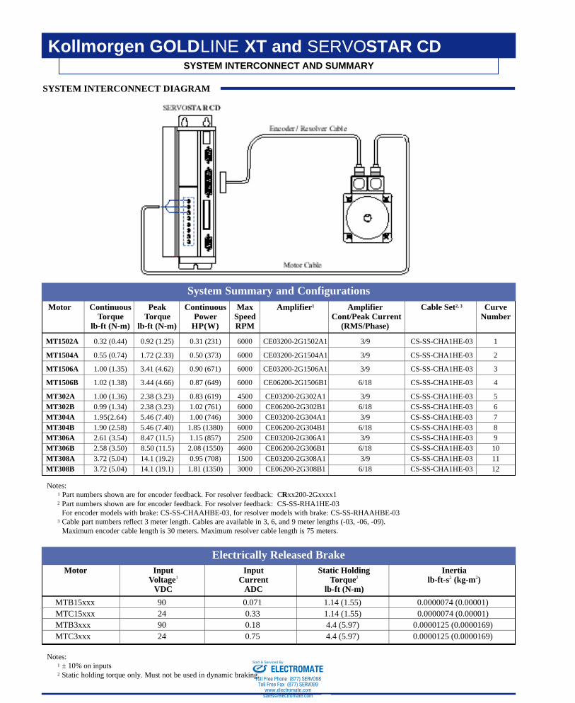
SYSTEM INTERCONNECT AND SUMMARY
MT1502A 0.32 (0.44) 0.92 (1.25) 0.31 (231) 6000 CE03200-2G1502A1 3/9 CS-SS-CHA1HE-03 1
MT1504A 0.55 (0.74) 1.72 (2.33) 0.50 (373) 6000 CE03200-2G1504A1 3/9 CS-SS-CHA1HE-03 2
MT1506A 1.00 (1.35) 3.41 (4.62) 0.90 (671) 6000 CE03200-2G1506A1 3/9 CS-SS-CHA1HE-03 3
MT1506B 1.02 (1.38) 3.44 (4.66) 0.87 (649) 6000 CE06200-2G1506B1 6/18 CS-SS-CHA1HE-03 4
MT302A 1.00 (1.36) 2.38 (3.23) 0.83 (619) 4500 CE03200-2G302A1 3/9 CS-SS-CHA1HE-03 5MT302B 0.99 (1.34) 2.38 (3.23) 1.02 (761) 6000 CE06200-2G302B1 6/18 CS-SS-CHA1HE-03 6MT304A 1.95(2.64) 5.46 (7.40) 1.00 (746) 3000 CE03200-2G304A1 3/9 CS-SS-CHA1HE-03 7MT304B 1.90 (2.58) 5.46 (7.40) 1.85 (1380) 6000 CE06200-2G304B1 6/18 CS-SS-CHA1HE-03 8MT306A 2.61 (3.54) 8.47 (11.5) 1.15 (857) 2500 CE03200-2G306A1 3/9 CS-SS-CHA1HE-03 9MT306B 2.58 (3.50) 8.50 (11.5) 2.08 (1550) 4600 CE06200-2G306B1 6/18 CS-SS-CHA1HE-03 10MT308A 3.72 (5.04) 14.1 (19.2) 0.95 (708) 1500 CE03200-2G308A1 3/9 CS-SS-CHA1HE-03 11MT308B 3.72 (5.04) 14.1 (19.1) 1.81 (1350) 3000 CE06200-2G308B1 6/18 CS-SS-CHA1HE-03 12
Motor Continuous Peak Continuous Max Amplifier1 Amplifier Cable Set2, 3 CurveTorque Torque Power Speed Cont/Peak Current Number
lb-ft (N-m) lb-ft (N-m) HP(W) RPM (RMS/Phase)
Motor Input Input Static Holding InertiaVoltage1 Current Torque2 lb-ft-s2 (kg-m2)
VDC ADC lb-ft (N-m)
System Summary and Configurations
Electrically Released Brake
Notes:1 Part numbers shown are for encoder feedback. For resolver feedback: CRxx200-2Gxxxx12 Part numbers shown are for encoder feedback. For resolver feedback: CS-SS-RHA1HE-03
For encoder models with brake: CS-SS-CHAAHBE-03, for resolver models with brake: CS-SS-RHAAHBE-033 Cable part numbers reflect 3 meter length. Cables are available in 3, 6, and 9 meter lengths (-03, -06, -09).
Maximum encoder cable length is 30 meters. Maximum resolver cable length is 75 meters.
Notes:1 ± 10% on inputs2 Static holding torque only. Must not be used in dynamic braking.
SYSTEM INTERCONNECT DIAGRAM
ELECTROMATEToll Free Phone (877) SERVO98
Toll Free Fax (877) SERV099www.electromate.com
Sold & Serviced By:
Kollmorgen GOLDLINE XT and SERVOSTAR CD
KOLLMORGEN • Radford, Virginia • 1-800-77 SERVO 19
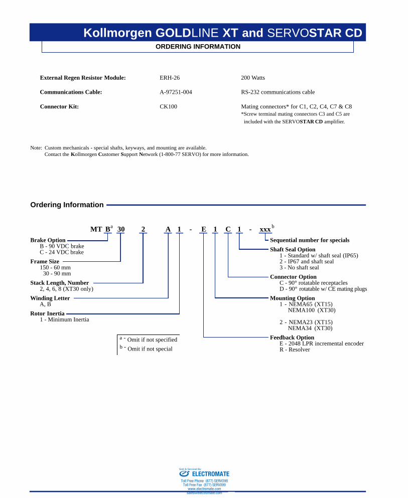
ORDERING INFORMATION
External Regen Resistor Module: ERH-26 200 Watts
Communications Cable: A-97251-004 RS-232 communications cable
Connector Kit: CK100 Mating connectors* for C1, C2, C4, C7 & C8*Screw terminal mating connectors C3 and C5 are
included with the SERVOSTAR CD amplifier.
Note: Custom mechanicals - special shafts, keyways, and mounting are available.Contact the Kollmorgen Customer Support Network (1-800-77 SERVO) for more information.
MT B 30 2 A 1 - E 1 C 1 - xxxBrake Option
B - 90 VDC brakeC - 24 VDC brake
Frame Size150 - 60 mm
30 - 90 mm
Stack Length, Number2, 4, 6, 8 (XT30 only)
Winding LetterA, B
Rotor Inertia1 - Minimum Inertia
Ordering Information
a b
a - Omit if not specifiedb - Omit if not special
Sequential number for specials
Shaft Seal Option1 - Standard w/ shaft seal (IP65)2 - IP67 and shaft seal3 - No shaft seal
Connector OptionC - 90° rotatable receptaclesD - 90° rotatable w/ CE mating plugs
Mounting Option1 - NEMA65 (XT15)
NEMA100 (XT30)
2 - NEMA23 (XT15)NEMA34 (XT30)
Feedback OptionE - 2048 LPR incremental encoderR - Resolver
ELECTROMATEToll Free Phone (877) SERVO98
Toll Free Fax (877) SERV099www.electromate.com
Sold & Serviced By:

ELECTROMATEToll Free Phone (877) SERVO98
Toll Free Fax (877) SERV099www.electromate.com
Sold & Serviced By: