Embed Size (px)
DESCRIPTION
Seminar "Sesam Present & Future" in Rio on Sept 2nd 2011, presented by Ole Jan Nekstad
Citation preview

Ole Jan Nekstad, Sesam Product Manager, DNV Software1 September 2011
1
SesamTM
40 years of success
GeniE – Shell modelling, status and directions

© Det Norske Veritas AS. All rights reserved.
SesamTM
1 September 2011
2
Shell modelling - status

© Det Norske Veritas AS. All rights reserved.
SesamTM
1 September 2011
3
Shell modelling functionality 4 main options – they are all based on curves
Skin/loft
Cover
Curve net interpolation
Extrude

© Det Norske Veritas AS. All rights reserved.
SesamTM
1 September 2011
4
Skin / loft curves Usually works fine with all types of curves
- If not, a trick may be to rebuild the curves with the same number of points
May get gaps between adjacent shells in the cross direction of the skinning direction
Workaround is to use a model curve from adjacent shell in further modelling
Gap, elements don’t share the same nodes

© Det Norske Veritas AS. All rights reserved.
SesamTM
1 September 2011
5
Use existing shell edge (model curve) Use model curve of shell edge to ensure topological congruency
May skin/loft, cover or net interpolate adjacent shell, as long as the model curve is used- Trimming of curves required?

© Det Norske Veritas AS. All rights reserved.
SesamTM
1 September 2011
6
Curve net interpolation Use net of interior and/or boundary curves
- Does not require trimming of curves- Requires common intersection points
OK

© Det Norske Veritas AS. All rights reserved.
SesamTM
1 September 2011
9
Internal edges Composite curves may give internal edges
- Same issue with skin/loft- Use global meshing rule Remove internal edges

© Det Norske Veritas AS. All rights reserved.
SesamTM
1 September 2011
10
Conclusion
Preferred approach:
Use polycurves and curve net interpolation
Need common intersection points

© Det Norske Veritas AS. All rights reserved.
SesamTM
1 September 2011
11
New features for shell modelling in GeniE v5.3-10 released April 2011
© Det Norske Veritas AS. All rights reserved.
SesamTM
1 September 2011
12
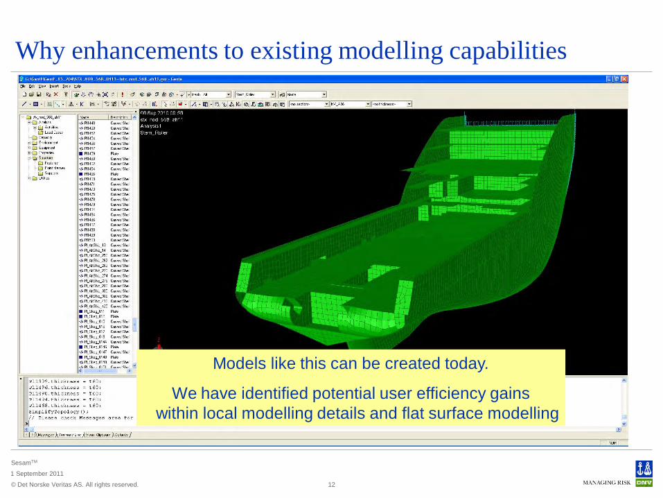
Why enhancements to existing modelling capabilities
Models like this can be created today.
We have identified potential user efficiency gainswithin local modelling details and flat surface modelling

© Det Norske Veritas AS. All rights reserved.
SesamTM
1 September 2011
13
Easier modelling of planar surfaces Create closed surfaces by single click using flat region feature
- Intuitive and simple to use.- Bounding by existing plates, beams and guide curves- No need to split lines
Insert Plate Flat Region to position cut-plane
Plates, beams and curves in cut-plane
Click inside area.Uses visible model

© Det Norske Veritas AS. All rights reserved.
SesamTM
1 September 2011
Vector from other object- local beam system- plate normal- 3-point plane normal, etc
14
Additional options in vector selection dialog

© Det Norske Veritas AS. All rights reserved.
SesamTM
1 September 2011
Additional options in snap plane and divide dialogs Plane defined by three points
15

© Det Norske Veritas AS. All rights reserved.
SesamTM
1 September 2011
17
More features for making geometry Scaling and offsetting of curves and surfaces makes it easier to make regular as
well as complex geometrical shapes- Scaling around a point is often used to create similar shapes for the purpose of making
structure and controlling finite element mesh, Edit Copy- Offsetting will create similar shape (line or surface) in a given distance

© Det Norske Veritas AS. All rights reserved.
SesamTM
1 September 2011
Meshing improvements Separated handling of mesh and loads use less peak memory
Conditional Regenerate Mesh- For large models, significant performance improvements are achieved when updating
analysis models- Does not have to regenerate mesh if only properties
or loads are changed. FEM file is updated instead.- Topology and mesh rule changes force new mesh
18

© Det Norske Veritas AS. All rights reserved.
SesamTM
1 September 2011
19
Ongoing modelling activities

© Det Norske Veritas AS. All rights reserved.
SesamTM
1 September 2011
20
Ongoing activities 64-bit version of GeniE – tentatively release date September 2011
- Performance improvements, “unlimited” memory available – important for large models (e.g. global FPSO model)
- ISO Joint Check “critical” joints, the option to compute “Ub from run” is now available- Sacs Import : Result combinations read into GeniE- Frame code checks : Results stored on HDF5 files, reducing chance of running out of
virtual memory

© Det Norske Veritas AS. All rights reserved.
SesamTM
1 September 2011
21
Ongoing activities – scheduled for release Q1/2012 Additional ways for modelling of guiding points and curves
Common representation of all curves using NURBS
Pictures from prototype implementation

© Det Norske Veritas AS. All rights reserved.
SesamTM
1 September 2011
27
Ongoing activities – some examples E.g. Different type of line representations
Classic cubic spline interpolation
G1 curve, consisting of linear and cubic segments, which
interpolates the given points
Polynomial line. Shape decided by
control points, but no interpolation
Shape-preserving interpolating spline
Guide Spline Poly Curve Bezier Curve S/P Spline Curve

© Det Norske Veritas AS. All rights reserved.
SesamTM
1 September 2011
29
Ongoing activities – some examples Bezier curve and control points – shape preserving curves
- Gives the user much more flexibility in creating almost any curve
Three control points Four control points –the middle point is used twice
Four control points

© Det Norske Veritas AS. All rights reserved.
SesamTM
1 September 2011
Ongoing activities – scheduled for release Q1/2012 New DXF import using the
Rhinoceros plug-in
Poly-lines supported with new NURBS implementations
30

© Det Norske Veritas AS. All rights reserved.
SesamTM
1 September 2011
Our biggest challenge when importing line data Real case example – importing data from NAPA
All looks fine!
But often lines do not intersect

© Det Norske Veritas AS. All rights reserved.
SesamTM
1 September 2011
Ongoing activities – scheduled for release Q1/2012 Mapping of one set of curves onto another
set, e.g. buttocks onto station curves/offset table- GeniE will propose a cleaning of non-matching
lines- User to decide which line to “move” to achieve
matching lines
All lines are matching
Two lines are not matching

© Det Norske Veritas AS. All rights reserved.
SesamTM
1 September 2011
33
Safeguarding life, property and the environment
www.dnv.com