Embed Size (px)
Citation preview
1
BalloonNet : A Deploying Method for
a Three-Dimensional Wireless Network
Surrounding a Building
Shinya Matsuo(1 Weihua Sun(2 Naoki Shibata(1
Tomoya Kitani(3 Minoru Ito(1
(1 -- Nara Institute of Science and Technology
(2 -- Osaka University
(3 -- Shizuoka University
2
Outline
• Research Background
• Related Research
• Problem Formulation
• Radio Propagation Model
• Proposed Method
• Simulation and Real Experiment
• Conclusion
3
Research Background
• Large Scale disasters occurs frequently
– Earthquake, Tsunami, Extreme Weather
• Advanced Health and Disaster Aid Network
– Electric Triage System
– Wireless network is necessary
– Restoration of Communications infrastructure is an urgent task
• Ad-hoc networks are attracting attention
– Building a wireless network using only network nodes without a
base station
[1]Tia Gao, Dan Greenspan, Matt Welsh, Radford R. Juang,Alex Alm, “Vital Signs Monitoring and
Patient Tracking Over a Wireless Network”, the 27th Annual International Conference of the IEEE EMBS, Shanghai, Sep 2005.
4
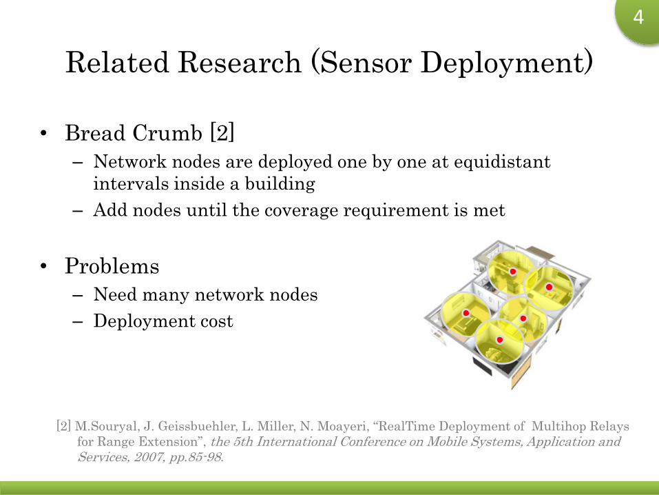
Related Research (Sensor Deployment)
• Bread Crumb [2]
– Network nodes are deployed one by one at equidistant
intervals inside a building
– Add nodes until the coverage requirement is met
• Problems
– Need many network nodes
– Deployment cost
[2] M.Souryal, J. Geissbuehler, L. Miller, N. Moayeri, “RealTime Deployment of Multihop Relays
for Range Extension”, the 5th International Conference on Mobile Systems, Application and Services, 2007, pp.85-98.
5
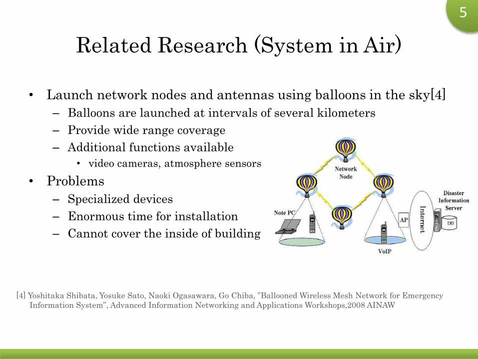
Related Research (System in Air)
• Launch network nodes and antennas using balloons in the sky[4]
– Balloons are launched at intervals of several kilometers
– Provide wide range coverage
– Additional functions available
• video cameras, atmosphere sensors
• Problems
– Specialized devices
– Enormous time for installation
– Cannot cover the inside of building
[4] Yoshitaka Shibata, Yosuke Sato, Naoki Ogasawara, Go Chiba, ”Ballooned Wireless Mesh Network for Emergency
Information System”, Advanced Information Networking and Applications Workshops,2008 AINAW
6
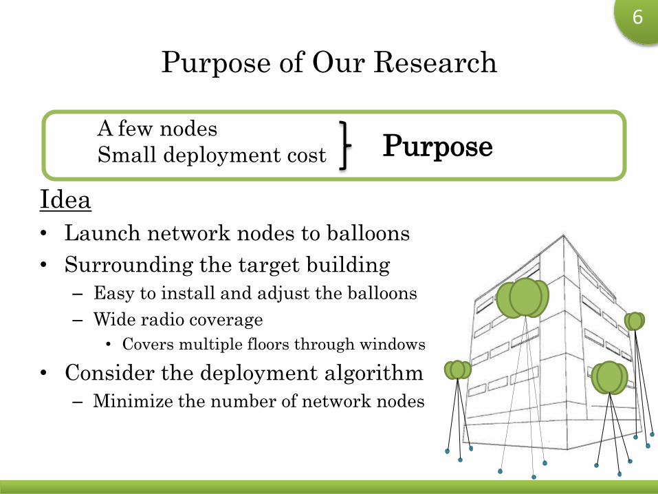
Purpose of Our Research
Idea
• Launch network nodes to balloons
• Surrounding the target building
– Easy to install and adjust the balloons
– Wide radio coverage
• Covers multiple floors through windows
• Consider the deployment algorithm
– Minimize the number of network nodes
PurposeA few nodes
Small deployment cost
7
Outline
• Research Background
• Related Research
• Problem Formulation
• Radio Propagation Model
• Proposed Method
• Simulation and Real Experiment
• Conclusion
8
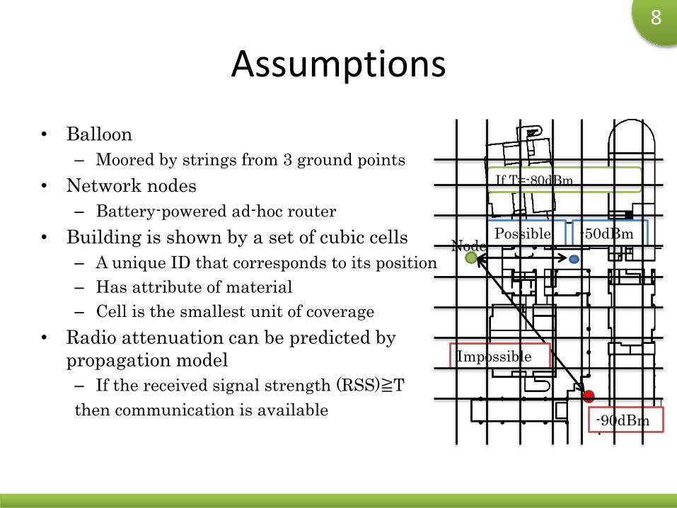
Assumptions
• Balloon
– Moored by strings from 3 ground points
• Network nodes
– Battery-powered ad-hoc router
• Building is shown by a set of cubic cells
– A unique ID that corresponds to its position
– Has attribute of material
– Cell is the smallest unit of coverage
• Radio attenuation can be predicted by
propagation model
– If the received signal strength (RSS)≧T
then communication is available
Node-50dBmPossible
-90dBm
Impossible
If T=-80dBm

9
Problem Formulation
• Input
– Floor plans of the target building
– Locations where balloons can be placed
– Radio propagation prediction model
– Requirement of number/ratio of coverage
• Output
– Location and the number of network nodes
• Objective
– Minimize the number of network nodes
10
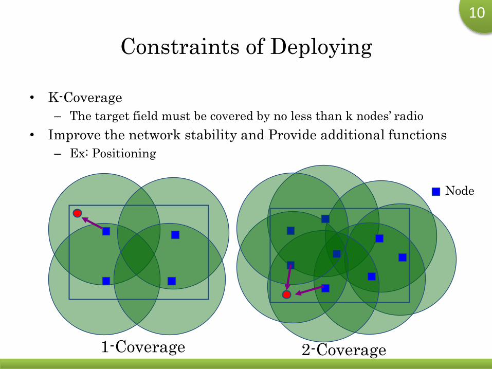
Constraints of Deploying
• K-Coverage
– The target field must be covered by no less than k nodes’ radio
• Improve the network stability and Provide additional functions
– Ex: Positioning
1-Coverage 2-Coverage
Node
11
Outline
• Research Background
• Related Research
• Problem Formulation
• Radio Propagation Model
• Proposed Method
• Simulation and Real Experiment
• Conclusion
12
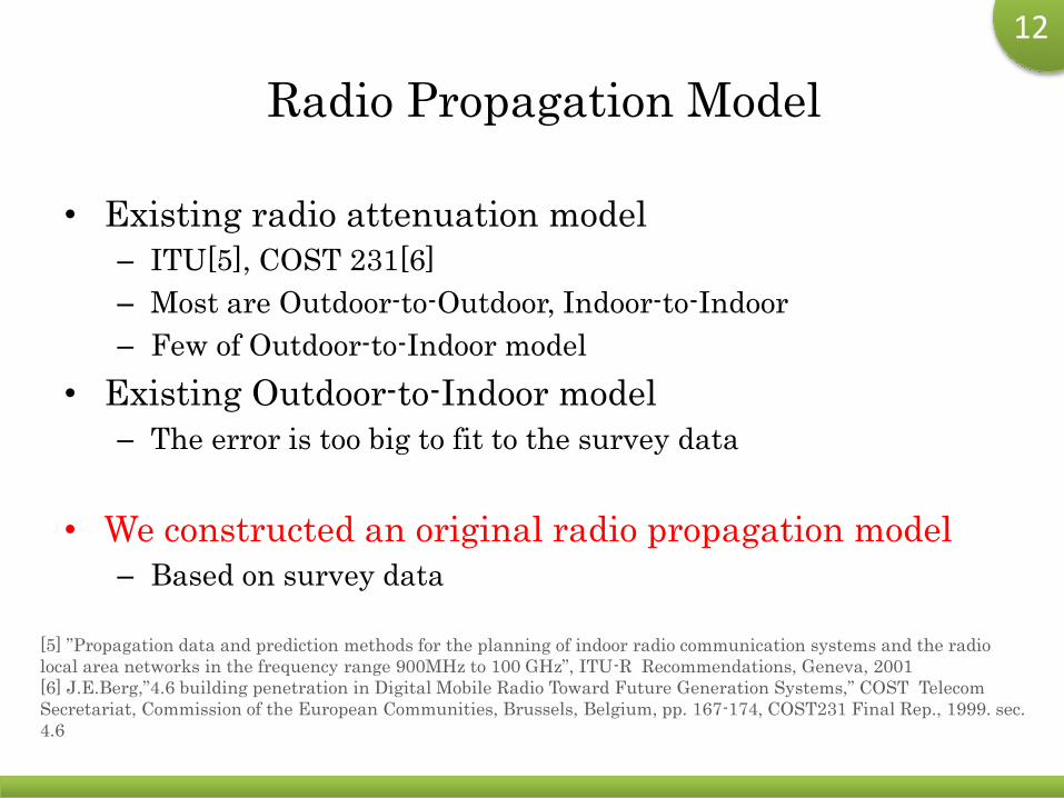
Radio Propagation Model
• Existing radio attenuation model
– ITU[5], COST 231[6]
– Most are Outdoor-to-Outdoor, Indoor-to-Indoor
– Few of Outdoor-to-Indoor model
• Existing Outdoor-to-Indoor model
– The error is too big to fit to the survey data
• We constructed an original radio propagation model
– Based on survey data
[5] ”Propagation data and prediction methods for the planning of indoor radio communication systems and the radio
local area networks in the frequency range 900MHz to 100 GHz”, ITU-R Recommendations, Geneva, 2001
[6] J.E.Berg,”4.6 building penetration in Digital Mobile Radio Toward Future Generation Systems,” COST Telecom
Secretariat, Commission of the European Communities, Brussels, Belgium, pp. 167-174, COST231 Final Rep., 1999. sec.
4.6
13
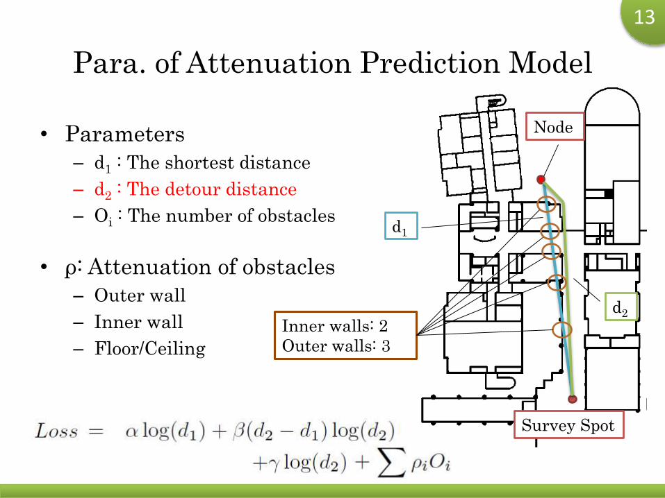
Para. of Attenuation Prediction Model
• Parameters
– d1 : The shortest distance
– d2 : The detour distance
– Oi : The number of obstacles
• ρ: Attenuation of obstacles
– Outer wall
– Inner wall
– Floor/Ceiling
Node
Survey Spot
d1
d2
Inner walls: 2
Outer walls: 3
14
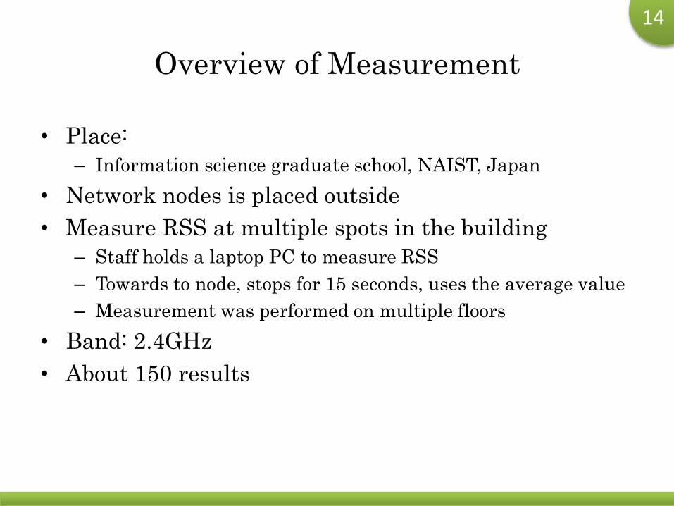
Overview of Measurement
• Place:
– Information science graduate school, NAIST, Japan
• Network nodes is placed outside
• Measure RSS at multiple spots in the building
– Staff holds a laptop PC to measure RSS
– Towards to node, stops for 15 seconds, uses the average value
– Measurement was performed on multiple floors
• Band: 2.4GHz
• About 150 results
15
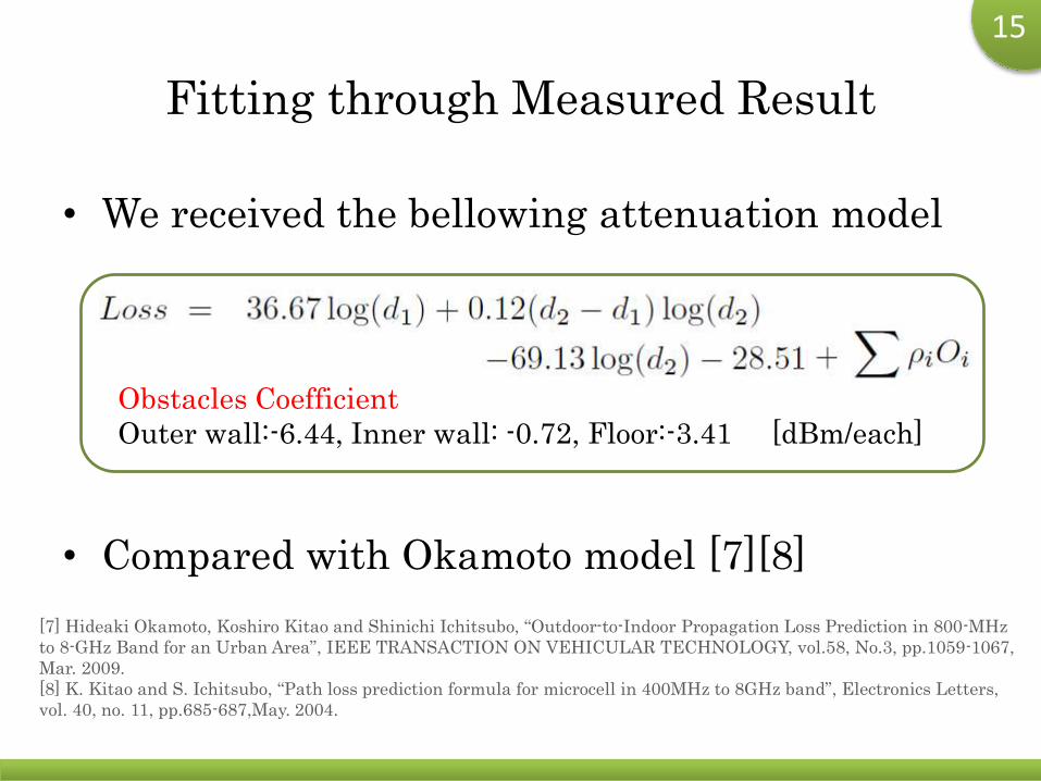
Fitting through Measured Result
• We received the bellowing attenuation model
• Compared with Okamoto model [7][8]
Obstacles Coefficient
Outer wall:-6.44, Inner wall: -0.72, Floor:-3.41 [dBm/each]
[7] Hideaki Okamoto, Koshiro Kitao and Shinichi Ichitsubo, “Outdoor-to-Indoor Propagation Loss Prediction in 800-MHz
to 8-GHz Band for an Urban Area”, IEEE TRANSACTION ON VEHICULAR TECHNOLOGY, vol.58, No.3, pp.1059-1067,
Mar. 2009.
[8] K. Kitao and S. Ichitsubo, “Path loss prediction formula for microcell in 400MHz to 8GHz band”, Electronics Letters,
vol. 40, no. 11, pp.685-687,May. 2004.
16
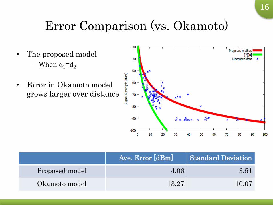
Error Comparison (vs. Okamoto)
• The proposed model
– When d1=d2
• Error in Okamoto model
grows larger over distance
Ave. Error [dBm] Standard Deviation
Proposed model 4.06 3.51
Okamoto model 13.27 10.07
17
Outline
• Research Background
• Related Research
• Problem Formulation
• Radio Propagation Model
• Proposed Method
• Simulation and Real Experiment
• Conclusion
18
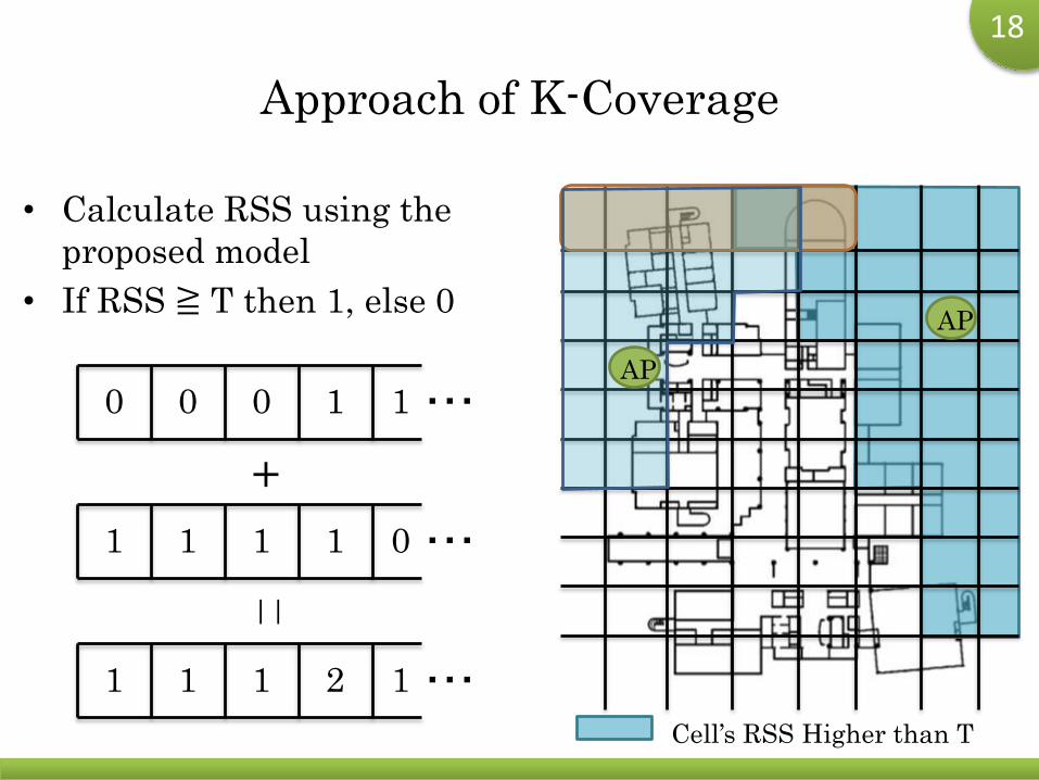
Approach of K-Coverage
• Calculate RSS using the
proposed model
• If RSS ≧ T then 1, else 0AP
Cell’s RSS Higher than T
・・・0 0 0 1 1AP
・・・1 1 1 1 0
+
・・・1 1 1 2 1
||
19
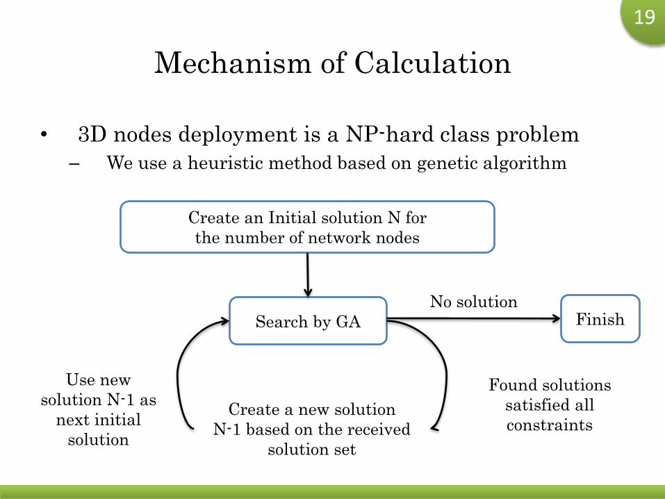
Mechanism of Calculation
• 3D nodes deployment is a NP-hard class problem
– We use a heuristic method based on genetic algorithm
Search by GA
Create a new solution
N-1 based on the received
solution set
FinishNo solution
Found solutions
satisfied all
constraints
Use new
solution N-1 as
next initial
solution
Create an Initial solution N for
the number of network nodes
20
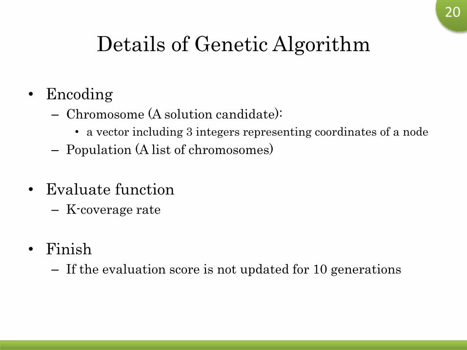
Details of Genetic Algorithm
• Encoding
– Chromosome (A solution candidate):
• a vector including 3 integers representing coordinates of a node
– Population (A list of chromosomes)
• Evaluate function
– K-coverage rate
• Finish
– If the evaluation score is not updated for 10 generations
21
Outline
• Research Background
• Related Research
• Problem Formulation
• Radio Propagation Model
• Proposed Method
• Simulation and Real Experiment
• Conclusion
22
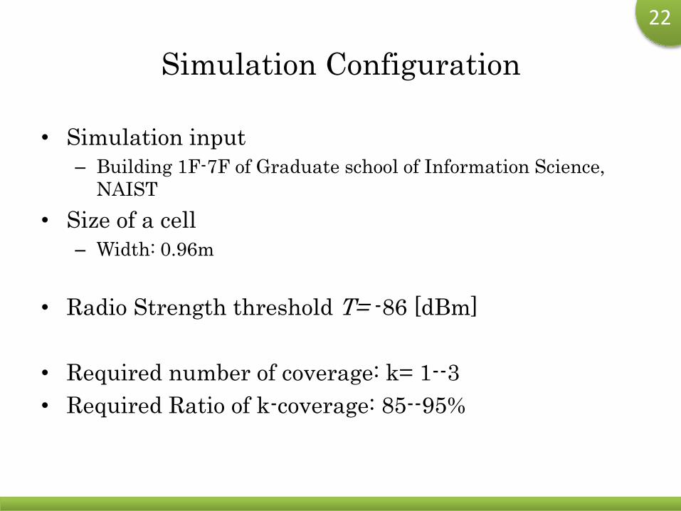
Simulation Configuration
• Simulation input
– Building 1F-7F of Graduate school of Information Science,
NAIST
• Size of a cell
– Width: 0.96m
• Radio Strength threshold T= -86 [dBm]
• Required number of coverage: k= 1--3
• Required Ratio of k-coverage: 85--95%
23
Benchmark Methods
• Repetitive Random Search (RS)
– Repetitively and randomly search better deployment plan
• Local Search (LS)
– Randomly create an initial solution
– Repetitively run local search based on the initial solution
• Bread Crumb (BC)
– The first one is set to the entrance of building
– Then set other nodes by same interval
– If the coverage does not meet requirement, then add node
– All nodes are set in the building
• Run above methods by same time to the proposed method
• Compared the average results of 50 trials
24
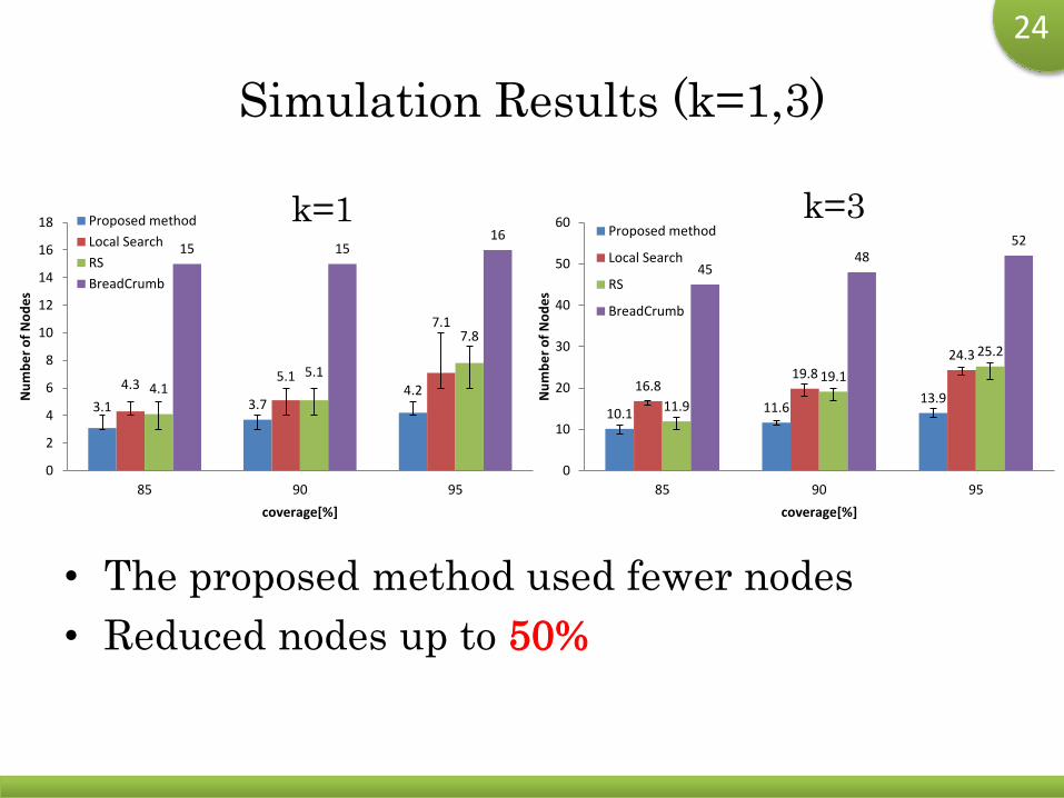
Simulation Results (k=1,3)
• The proposed method used fewer nodes
• Reduced nodes up to 50%
k=1 k=3
3.1 3.74.24.3
5.1
7.1
4.15.1
7.8
15 1516
0
2
4
6
8
10
12
14
16
18
85 90 95
Nu
mb
er
of
No
de
s
coverage[%]
Proposed method
Local Search
RS
BreadCrumb
10.1 11.613.9
16.819.8
24.3
11.9
19.1
25.2
4548
52
0
10
20
30
40
50
60
85 90 95
Nu
mb
er
of
No
de
s
coverage[%]
Proposed method
Local Search
RS
BreadCrumb

25
Real Experiments
• We conducted a real world experiment to investigate
the result of simulation
– Used the solution from simulation
– Measured radio attenuation
• We measured more than 300 spots on 1F-2F of the
target building
• Deployment requirement
– 1-cover, node number 3, coverage rate 92.6%
26
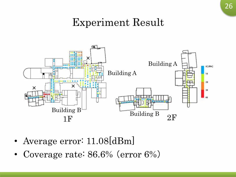
Experiment Result
• Average error: 11.08[dBm]
• Coverage rate: 86.6% (error 6%)
1F 2F
Building A
Building B
Building A
Building B
×
××
27
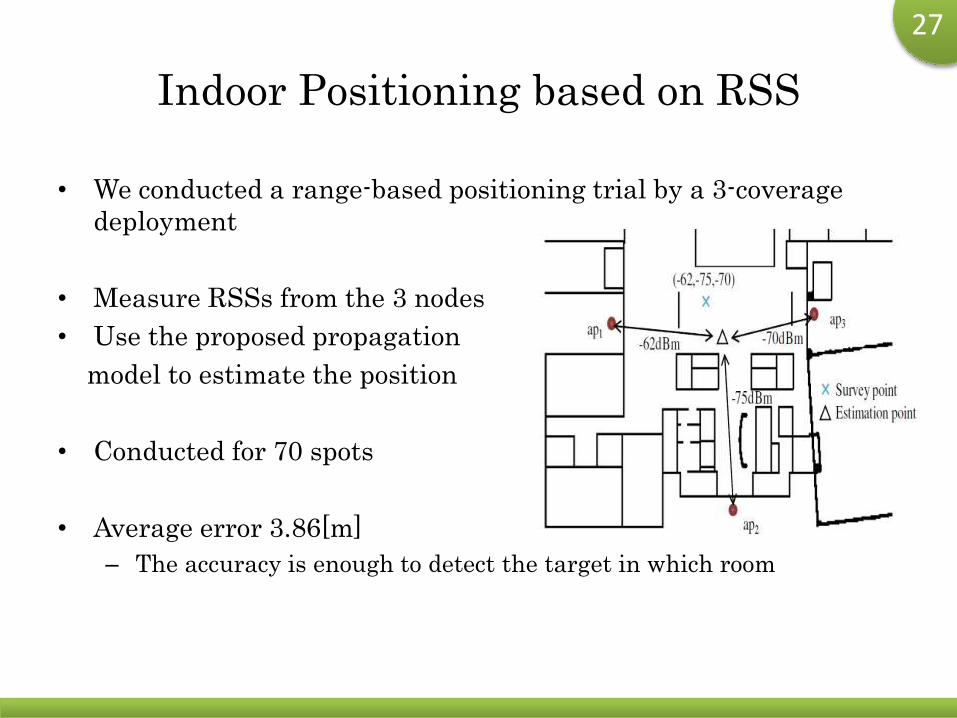
Indoor Positioning based on RSS
• We conducted a range-based positioning trial by a 3-coverage
deployment
• Measure RSSs from the 3 nodes
• Use the proposed propagation
model to estimate the position
• Conducted for 70 spots
• Average error 3.86[m]
– The accuracy is enough to detect the target in which room
28
Conclusion
• We proposed an efficient deploying method to install
network nodes surrounding buildings in disaster area
– Proposed an original radio attenuation model
– Used a heuristic algorithm based on GA
• Future work
– Improve the algorithm to reduce computing complexity
– Improve the propagation model to apply to general
environment
29
Shinya Matsuo, Weihua Sun, Naoki Shibata,
Tomoya Kitani and Minoru Ito : "BalloonNet: A
Deploying Method for a Three-Dimensional
Wireless Network Surrounding a Building," in
Proc. of the Eighth International Conference on
Broadband and Wireless Computing,
Communication and Applications (BWCCA-2013),
pp.120-127.
DOI:10.1109/BWCCA.2013.28, [ PDF ]