Embed Size (px)
Citation preview
DC201R Series
ADVANCED MOTION CONTROLS 3805 Calle Tecate, Camarillo, CA 93012 Tel: (805) 389-1935, Fax: (805) 389-1165
Page 1 of 13
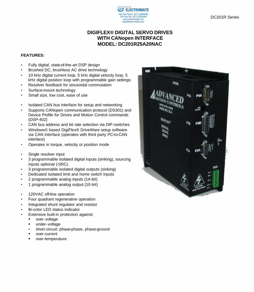
DIGIFLEX® DIGITAL SERVO DRIVES WITH CANopen INTERFACE MODEL: DC201R25A20NAC
FEATURES: • Fully digital, state-of-the-art DSP design • Brushed DC, brushless AC drive technology • 10 kHz digital current loop, 5 kHz digital velocity loop, 5
kHz digital position loop with programmable gain settings • Resolver feedback for sinusoidal commutation • Surface-mount technology • Small size, low cost, ease of use • Isolated CAN bus interface for setup and networking • Supports CANopen communication protocol (DS301) and
Device Profile for Drives and Motion Control commands (DSP-402)
• CAN bus address and bit rate selection via DIP-switches • Windows© based DigiFlex® DriveWare setup software
via CAN interface (operates with third party PC-to-CAN interface)
• Operates in torque, velocity or position mode • Single resolver input • 3 programmable isolated digital inputs (sinking), sourcing
inputs optional (-SRC). • 3 programmable isolated digital outputs (sinking) • Dedicated isolated limit and home switch inputs • 2 programmable analog inputs (14-bit) • 1 programmable analog output (10-bit) • 120VAC off-line operation • Four quadrant regenerative operation • Integrated shunt regulator and resistor • Bi-color LED status indicator • Extensive built-in protection against: § over-voltage § under-voltage • short-circuit: phase-phase, phase-ground § over-current § over-temperature
ELECTROMATEToll Free Phone (877) SERVO98
Toll Free Fax (877) SERV099www.electromate.com
Sold & Serviced By:
ADVANCED MOTION CONTROLS DC201R Series
Page 2 of 13
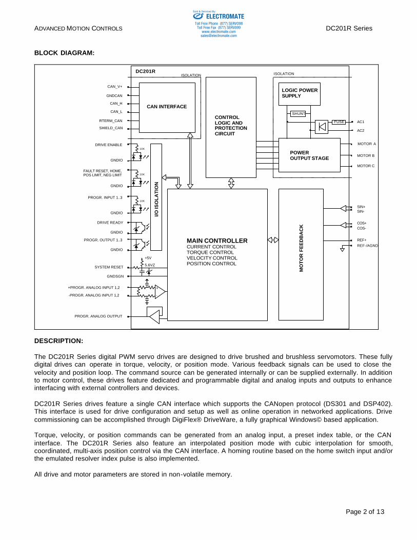
BLOCK DIAGRAM:
MOTOR A
MOTOR B
MOTOR C
10K
10K
10K
DRIVE READY
PROGR. OUTPUT 1..3
GNDIO
GNDIO
GNDIO
GNDIO
GNDIO
DRIVE ENABLE
+PROGR. ANALOG INPUT 1,2
-PROGR. ANALOG INPUT 1,2
PROGR. ANALOG OUTPUT
SIN+SIN-
COS+COS-
REF+REF-/AGND
I/O IS
OL
AT
ION
CAN INTERFACE
MO
TO
R F
EE
DB
AC
K
MAIN CONTROLLERCURRENT CONTROLTORQUE CONTROLVELOCITY CONTROLPOSITION CONTROL
+
-
+5V
5.6VZ
LOGIC POWER SUPPLY
CONTROL LOGIC AND PROTECTION CIRCUIT
SYSTEM RESET
GNDSGN
CAN_H
CAN_L
GNDCAN
SHIELD_CAN
RTERM_CAN
CAN_V+
AC1
AC2
POWER OUTPUT STAGE
FAULT RESET, HOME, POS LIMIT, NEG LIMIT
PROGR. INPUT 1..3
DC201RISOLATION ISOLATION
FUSE
SHUNT
DESCRIPTION: The DC201R Series digital PWM servo drives are designed to drive brushed and brushless servomotors. These fully digital drives can operate in torque, velocity, or position mode. Various feedback signals can be used to close the velocity and position loop. The command source can be generated internally or can be supplied externally. In addition to motor control, these drives feature dedicated and programmable digital and analog inputs and outputs to enhance interfacing with external controllers and devices. DC201R Series drives feature a single CAN interface which supports the CANopen protocol (DS301 and DSP402). This interface is used for drive configuration and setup as well as online operation in networked applications. Drive commissioning can be accomplished through DigiFlex® DriveWare, a fully graphical Windows© based application. Torque, velocity, or position commands can be generated from an analog input, a preset index table, or the CAN interface. The DC201R Series also feature an interpolated position mode with cubic interpolation for smooth, coordinated, multi-axis position control via the CAN interface. A homing routine based on the home switch input and/or the emulated resolver index pulse is also implemented. All drive and motor parameters are stored in non-volatile memory.
ELECTROMATEToll Free Phone (877) SERVO98
Toll Free Fax (877) SERV099www.electromate.com
Sold & Serviced By:
ADVANCED MOTION CONTROLS DC201R Series
Page 3 of 13
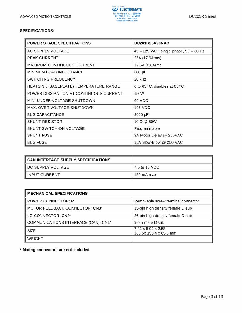
SPECIFICATIONS:
POWER STAGE SPECIFICATIONS DC201R25A20NAC
AC SUPPLY VOLTAGE 45 – 125 VAC, single phase, 50 – 60 Hz
PEAK CURRENT 25A (17.6Arms)
MAXIMUM CONTINUOUS CURRENT 12.5A (8.8Arms
MINIMUM LOAD INDUCTANCE 600 µH
SWITCHING FREQUENCY 20 kHz
HEATSINK (BASEPLATE) TEMPERATURE RANGE 0 to 65 ºC, disables at 65 ºC
POWER DISSIPATION AT CONTINUOUS CURRENT 150W
MIN. UNDER-VOLTAGE SHUTDOWN 60 VDC
MAX. OVER-VOLTAGE SHUTDOWN 195 VDC
BUS CAPACITANCE 3000 µF
SHUNT RESISTOR 10 O @ 50W
SHUNT SWITCH-ON VOLTAGE Programmable
SHUNT FUSE 3A Motor Delay @ 250VAC
BUS FUSE 15A Slow-Blow @ 250 VAC
CAN INTERFACE SUPPLY SPECIFICATIONS
DC SUPPLY VOLTAGE 7.5 to 13 VDC
INPUT CURRENT 150 mA max.
MECHANICAL SPECIFICATIONS
POWER CONNECTOR: P1 Removable screw terminal connector
MOTOR FEEDBACK CONNECTOR: CN3* 15-pin high density female D-sub
I/O CONNECTOR: CN2* 26-pin high density female D-sub
COMMUNICATIONS INTERFACE (CAN): CN1* 9-pin male D-sub
SIZE 7.42 x 5.92 x 2.58 188.5x 150.4 x 65.5 mm
WEIGHT
* Mating connectors are not included.
ELECTROMATEToll Free Phone (877) SERVO98
Toll Free Fax (877) SERV099www.electromate.com
Sold & Serviced By:
ADVANCED MOTION CONTROLS DC201R Series
Page 4 of 13
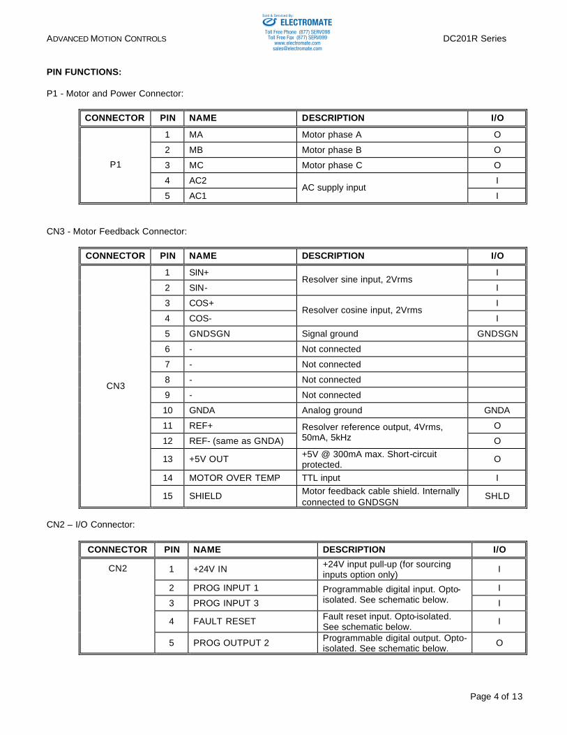
PIN FUNCTIONS: P1 - Motor and Power Connector:
CONNECTOR PIN NAME DESCRIPTION I/O
1 MA Motor phase A O
2 MB Motor phase B O
3 MC Motor phase C O
4 AC2 I
P1
5 AC1 AC supply input
I
CN3 - Motor Feedback Connector:
CONNECTOR PIN NAME DESCRIPTION I/O
1 SIN+ I
2 SIN- Resolver sine input, 2Vrms
I
3 COS+ I
4 COS- Resolver cosine input, 2Vrms
I
5 GNDSGN Signal ground GNDSGN
6 - Not connected
7 - Not connected
8 - Not connected
9 - Not connected
10 GNDA Analog ground GNDA
11 REF+ O
12 REF- (same as GNDA)
Resolver reference output, 4Vrms, 50mA, 5kHz O
13 +5V OUT +5V @ 300mA max. Short-circuit protected.
O
14 MOTOR OVER TEMP TTL input I
CN3
15 SHIELD Motor feedback cable shield. Internally connected to GNDSGN
SHLD
CN2 – I/O Connector:
CONNECTOR PIN NAME DESCRIPTION I/O
1 +24V IN +24V input pull-up (for sourcing inputs option only)
I
2 PROG INPUT 1 I
3 PROG INPUT 3
Programmable digital input. Opto-isolated. See schematic below. I
4 FAULT RESET Fault reset input. Opto-isolated. See schematic below.
I
CN2
5 PROG OUTPUT 2 Programmable digital output. Opto-isolated. See schematic below.
O
ELECTROMATEToll Free Phone (877) SERVO98
Toll Free Fax (877) SERV099www.electromate.com
Sold & Serviced By:
ADVANCED MOTION CONTROLS DC201R Series
Page 5 of 13
GNDIO
OUTPUT
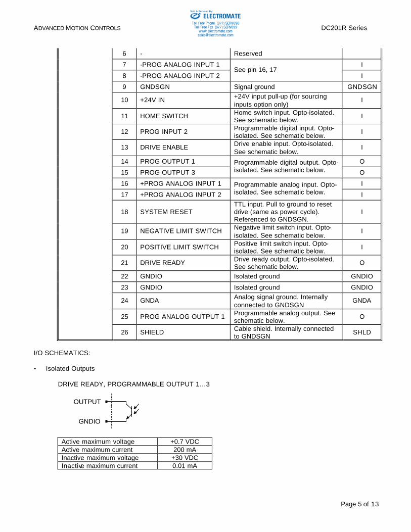
6 - Reserved
7 -PROG ANALOG INPUT 1 I
8 -PROG ANALOG INPUT 2 See pin 16, 17
I
9 GNDSGN Signal ground GNDSGN
10 +24V IN +24V input pull-up (for sourcing inputs option only)
I
11 HOME SWITCH Home switch input. Opto-isolated. See schematic below.
I
12 PROG INPUT 2 Programmable digital input. Opto-isolated. See schematic below.
I
13 DRIVE ENABLE Drive enable input. Opto-isolated. See schematic below.
I
14 PROG OUTPUT 1 O
15 PROG OUTPUT 3
Programmable digital output. Opto-isolated. See schematic below. O
16 +PROG ANALOG INPUT 1 I
17 +PROG ANALOG INPUT 2
Programmable analog input. Opto-isolated. See schematic below. I
18 SYSTEM RESET TTL input. Pull to ground to reset drive (same as power cycle). Referenced to GNDSGN.
I
19 NEGATIVE LIMIT SWITCH Negative limit switch input. Opto-isolated. See schematic below.
I
20 POSITIVE LIMIT SWITCH Positive limit switch input. Opto-isolated. See schematic below.
I
21 DRIVE READY Drive ready output. Opto-isolated. See schematic below.
O
22 GNDIO Isolated ground GNDIO
23 GNDIO Isolated ground GNDIO
24 GNDA Analog signal ground. Internally connected to GNDSGN
GNDA
25 PROG ANALOG OUTPUT 1 Programmable analog output. See schematic below.
O
26 SHIELD Cable shield. Internally connected to GNDSGN
SHLD
I/O SCHEMATICS: • Isolated Outputs
DRIVE READY, PROGRAMMABLE OUTPUT 1…3
Active maximum voltage +0.7 VDC Active maximum current 200 mA Inactive maximum voltage +30 VDC Inactive maximum current 0.01 mA
ELECTROMATEToll Free Phone (877) SERVO98
Toll Free Fax (877) SERV099www.electromate.com
Sold & Serviced By:
ADVANCED MOTION CONTROLS DC201R Series
Page 6 of 13
GNDIO
INPUT10K
INPUT
+24V IN10K
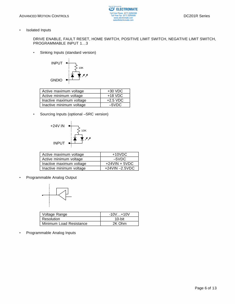
• Isolated Inputs DRIVE ENABLE, FAULT RESET, HOME SWITCH, POSITIVE LIMIT SWITCH, NEGATIVE LIMIT SWITCH, PROGRAMMABLE INPUT 1…3
• Sinking Inputs (standard version)
Active maximum voltage +30 VDC Active minimum voltage +18 VDC Inactive maximum voltage +2.5 VDC Inactive minimum voltage –5VDC
• Sourcing Inputs (optional –SRC version)
Active maximum voltage +10VDC Active minimum voltage –5VDC Inactive maximum voltage +24VIN + 5VDC Inactive minimum voltage +24VIN –2.5VDC
• Programmable Analog Output
Voltage Range -10V…+10V Resolution 10-bit Minimum Load Resistance 2K Ohm
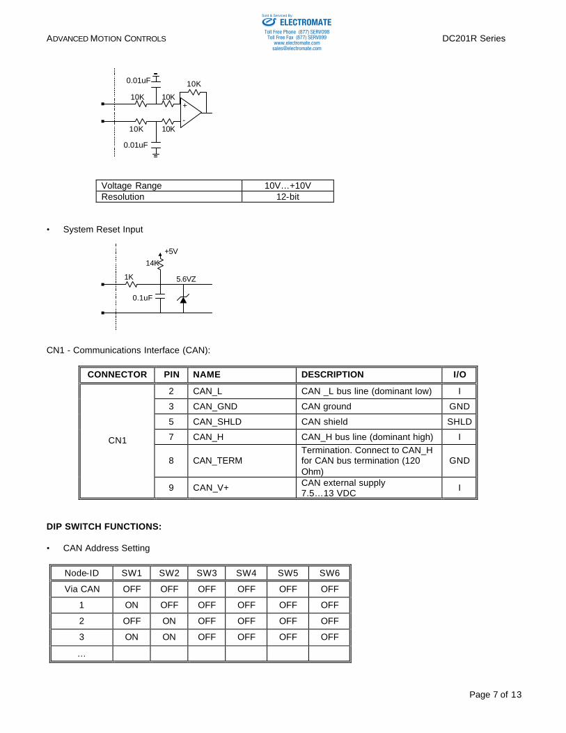
• Programmable Analog Inputs
ELECTROMATEToll Free Phone (877) SERVO98
Toll Free Fax (877) SERV099www.electromate.com
Sold & Serviced By:
ADVANCED MOTION CONTROLS DC201R Series
Page 7 of 13
+
-
10K 10K
10K
10K10K
0.01uF
0.01uF
Voltage Range 10V…+10V Resolution 12-bit
• System Reset Input
CN1 - Communications Interface (CAN):
CONNECTOR PIN NAME DESCRIPTION I/O
2 CAN_L CAN _L bus line (dominant low) I
3 CAN_GND CAN ground GND
5 CAN_SHLD CAN shield SHLD
7 CAN_H CAN_H bus line (dominant high) I
8 CAN_TERM Termination. Connect to CAN_H for CAN bus termination (120 Ohm)
GND
CN1
9 CAN_V+ CAN external supply 7.5…13 VDC
I
DIP SWITCH FUNCTIONS: • CAN Address Setting
Node-ID SW1 SW2 SW3 SW4 SW5 SW6
Via CAN OFF OFF OFF OFF OFF OFF
1 ON OFF OFF OFF OFF OFF
2 OFF ON OFF OFF OFF OFF
3 ON ON OFF OFF OFF OFF
…
+5V
5.6VZ
14K
1K
0.1uF
ELECTROMATEToll Free Phone (877) SERVO98
Toll Free Fax (877) SERV099www.electromate.com
Sold & Serviced By:
ADVANCED MOTION CONTROLS DC201R Series
Page 8 of 13
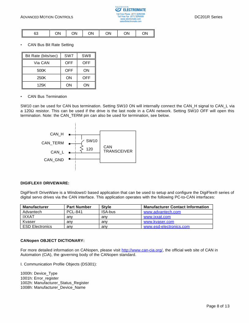
63 ON ON ON ON ON ON
• CAN Bus Bit Rate Setting
Bit Rate (bits/sec) SW7 SW8
Via CAN OFF OFF
500K OFF ON
250K ON OFF
125K ON ON
• CAN Bus Termination SW10 can be used for CAN bus termination. Setting SW10 ON will internally connect the CAN_H signal to CAN_L via a 120Ω resistor. This can be used if the drive is the last node in a CAN network. Setting SW10 OFF will open this termination. Note: the CAN_TERM pin can also be used for termination, see below.
DIGIFLEX® DRIVEWARE: DigiFlex® DriveWare is a Windows© based application that can be used to setup and configure the DigiFlex® series of digital servo drives via the CAN interface. This application operates with the following PC-to-CAN interfaces: Manufacturer Part Number Style Manufacturer Contact Information Advantech PCL-841 ISA-bus www.advantech.com IXXAT any any www.ixxat.com Kvaser any any www.kvaser.com ESD Electronics any any www.esd-electronics.com
CANopen OBJECT DICTIONARY: For more detailed information on CANopen, please visit http://www.can-cia.org/, the official web site of CAN in Automation (CiA), the governing body of the CANopen standard. I. Communication Profile Objects (DS301): 1000h: Device_Type 1001h: Error_register 1002h: Manufacturer_Status_Register 1008h: Manufacturer_Device_Name
CAN TRANSCEIVER
CAN_H
CAN_L
CAN_GND
SW10
120
CAN_TERM
ELECTROMATEToll Free Phone (877) SERVO98
Toll Free Fax (877) SERV099www.electromate.com
Sold & Serviced By:
ADVANCED MOTION CONTROLS DC201R Series
Page 9 of 13
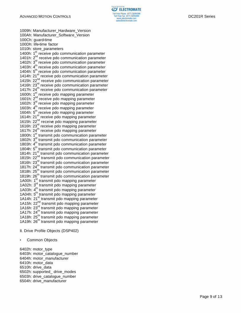
1009h: Manufacturer_Hardware_Version 100Ah: Manufacturer_Software_Version 100Ch: guard-time 100Dh: life-time factor 1010h: store_parameters 1400h: 1st receive pdo communication parameter 1401h: 2nd receive pdo communication parameter 1402h: 3rd receive pdo communication parameter 1403h: 4th receive pdo communication parameter 1404h: 5th receive pdo communication parameter 1414h: 21st receive pdo communication parameter 1415h: 22nd receive pdo communication parameter 1416h: 23rd receive pdo communication parameter 1417h: 24th receive pdo communication parameter 1600h: 1st receive pdo mapping parameter 1601h: 2nd receive pdo mapping parameter 1602h: 3rd receive pdo mapping parameter 1603h: 4th receive pdo mapping parameter 1604h: 5th receive pdo mapping parameter 1614h: 21st receive pdo mapping parameter 1615h: 22nd receive pdo mapping parameter 1616h: 23rd receive pdo mapping parameter 1617h: 24th receive pdo mapping parameter 1800h: 1st transmit pdo communication parameter 1802h: 3rd transmit pdo communication parameter 1803h: 4th transmit pdo communication parameter 1804h: 5th transmit pdo communication parameter 1814h: 21st transmit pdo communication parameter 1815h: 22nd transmit pdo communication parameter 1816h: 23rd transmit pdo communication parameter 1817h: 24th transmit pdo communication parameter 1818h: 25th transmit pdo communication parameter 1819h: 26th transmit pdo communication parameter 1A00h: 1st transmit pdo mapping parameter 1A02h: 3rd transmit pdo mapping parameter 1A03h: 4th transmit pdo mapping parameter 1A04h: 5th transmit pdo mapping parameter 1A14h: 21st transmit pdo mapping parameter 1A15h: 22nd transmit pdo mapping parameter 1A16h: 23rd transmit pdo mapping parameter 1A17h: 24th transmit pdo mapping parameter 1A18h: 25th transmit pdo mapping parameter 1A19h: 26th transmit pdo mapping parameter II. Drive Profile Objects (DSP402) • Common Objects 6402h: motor_type 6403h: motor_catalogue_number 6404h: motor_manufacturer 6410h: motor_data 6510h: drive_data 6502h: supported_ drive_modes 6503h: drive_catalogue_number 6504h: drive_manufacturer
ELECTROMATEToll Free Phone (877) SERVO98
Toll Free Fax (877) SERV099www.electromate.com
Sold & Serviced By:
ADVANCED MOTION CONTROLS DC201R Series
Page 10 of 13
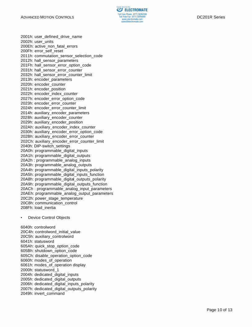
2001h: user_defined_drive_name 2002h: user_units 200Eh: active_non_fatal_errors 200Fh: error_self_reset 2011h: commutation_sensor_selection_code 2012h: hall_sensor_parameters 201Fh: hall_sensor_error_option_code 2031h: hall_sensor_error_counter 2032h: hall_sensor_error_counter_limit 2013h: encoder_parameters 2020h: encoder_counter 2021h: encoder_position 2022h: encoder_index_counter 2027h: encoder_error_option_code 2023h: encoder_error_counter 2024h: encoder_error_counter_limit 2014h: auxiliary_encoder_parameters 2028h: auxiliary_encoder_counter 2029h: auxiliary_encoder_position 202Ah: auxiliary_encoder_index_counter 2030h: auxiliary_encoder_error_option_code 202Bh: auxiliary_encoder_error_counter 202Ch: auxiliary_encoder_error_counter_limit 2040h: DIP-switch_settings 20A0h: programmable_digital_inputs 20A1h: programmable_digital_outputs 20A2h : programmable_analog_inputs 20A3h: programmable_analog_outputs 20A4h: programmable_digital_inputs_polarity 20A5h: programmable_digital_inputs_function 20A8h: programmable_digital_outputs_polarity 20A9h: programmable_digital_outputs_function 20ACh : programmable_analog_input_parameters 20AEh: programmable_analog_output_parameters 20C2h: power_stage_temperature 20C8h: communication_control 208Fh: load_inertia • Device Control Objects 6040h: controlword 20C4h: controlword_initial_value 20C5h: auxiliary_controlword 6041h: statusword 605Ah: quick_stop_option_code 605Bh: shutdown_option_code 605Ch: disable_operation_option_code 6060h: modes_of_operation 6061h: modes_of_operation display 2000h: statusword_1 2004h: dedicated_digital_inputs 2005h: dedicated_digital_outputs 2006h: dedicated_digital_inputs_polarity 2007h: dedicated_digital_outputs_polarity 2049h: invert_command
ELECTROMATEToll Free Phone (877) SERVO98
Toll Free Fax (877) SERV099www.electromate.com
Sold & Serviced By:
ADVANCED MOTION CONTROLS DC201R Series
Page 11 of 13
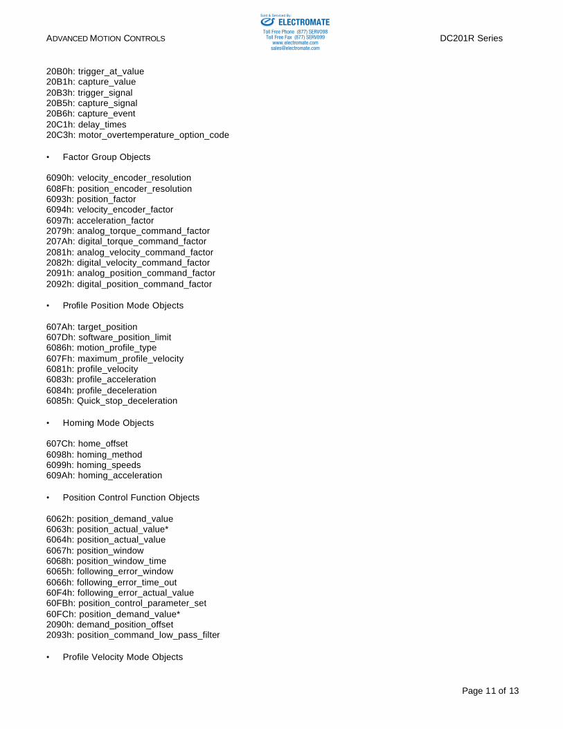
20B0h: trigger_at_value 20B1h: capture_value 20B3h: trigger_signal 20B5h: capture_signal 20B6h: capture_event 20C1h: delay_times 20C3h: motor_overtemperature_option_code • Factor Group Objects 6090h: velocity_encoder_resolution 608Fh: position_encoder_resolution 6093h: position_factor 6094h: velocity_encoder_factor 6097h: acceleration_factor 2079h: analog_torque_command_factor 207Ah: digital_torque_command_factor 2081h: analog_velocity_command_factor 2082h: digital_velocity_command_factor 2091h: analog_position_command_factor 2092h: digital_position_command_factor • Profile Position Mode Objects 607Ah: target_position 607Dh: software_position_limit 6086h: motion_profile_type 607Fh: maximum_profile_velocity 6081h: profile_velocity 6083h: profile_acceleration 6084h: profile_deceleration 6085h: Quick_stop_deceleration • Homing Mode Objects 607Ch: home_offset 6098h: homing_method 6099h: homing_speeds 609Ah: homing_acceleration • Position Control Function Objects 6062h: position_demand_value 6063h: position_actual_value* 6064h: position_actual_value 6067h: position_window 6068h: position_window_time 6065h: following_error_window 6066h: following_error_time_out 60F4h: following_error_actual_value 60FBh: position_control_parameter_set 60FCh: position_demand_value* 2090h: demand_position_offset 2093h: position_command_low_pass_filter • Profile Velocity Mode Objects
ELECTROMATEToll Free Phone (877) SERVO98
Toll Free Fax (877) SERV099www.electromate.com
Sold & Serviced By:
ADVANCED MOTION CONTROLS DC201R Series
Page 12 of 13
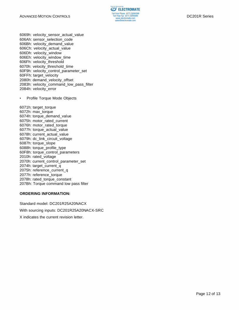
6069h: velocity_sensor_actual_value 606Ah: sensor_selection_code 606Bh: velocity_demand_value 606Ch: velocity_actual_value 606Dh: velocity_window 606Eh: velocity_window_time 606Fh: velocity_threshold 6070h: velocity_threshold_time 60F9h: velocity_control_parameter_set 60FFh: target_velocity 2080h: demand_velocity_offset 2083h: velocity_command_low_pass_filter 2084h: velocity_error • Profile Torque Mode Objects 6071h: target_torque 6072h: max_torque 6074h: torque_demand_value 6075h: motor_rated_current 6076h: motor_rated_torque 6077h: torque_actual_value 6078h: current_actual_value 6079h: dc_link_circuit_voltage 6087h: torque_slope 6088h: torque_profile_type 60F8h: torque_control_parameters 2010h: rated_voltage 2070h: current_control_parameter_set 2074h: target_current_q 2075h: reference_current_q 2077h: reference_torque 2078h: rated_torque_constant 207Bh: Torque command low pass filter ORDERING INFORMATION: Standard model: DC201R25A20NACX
With sourcing inputs: DC201R25A20NACX-SRC
X indicates the current revision letter.
ELECTROMATEToll Free Phone (877) SERVO98
Toll Free Fax (877) SERV099www.electromate.com
Sold & Serviced By:
ADVANCED MOTION CONTROLS DC201R Series
Page 13 of 13
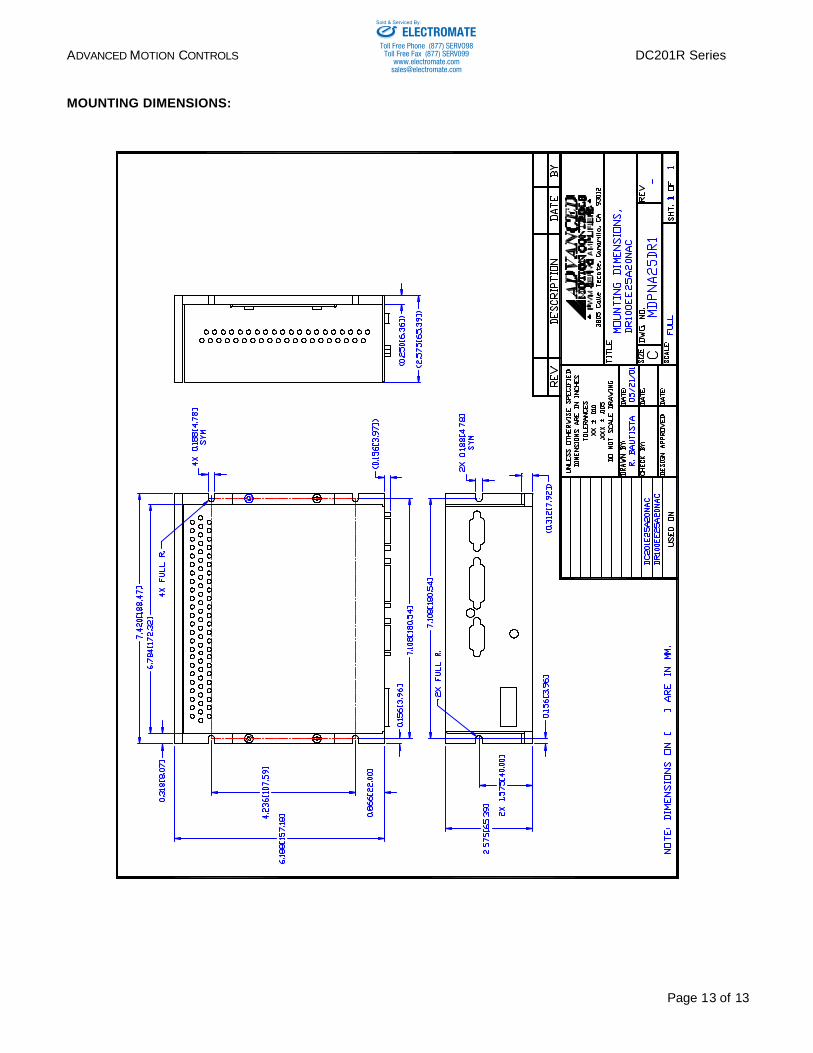
MOUNTING DIMENSIONS:
ELECTROMATEToll Free Phone (877) SERVO98
Toll Free Fax (877) SERV099www.electromate.com
Sold & Serviced By: