Embed Size (px)
Citation preview
M/V™ Series Servo Drive AVB200A100
Release Date:
9/10/2013 Revision:
2.01 Advanced Motion Controls · 3805 Calle Tecate, Camarillo, CA, 93012
ph# 805-389-1935 · fx# 805-389-1165· www.a-m-c.com Page 1 of 12
Description Power Range
AVB200A100 servo amplifiers are designed to drive brushless DC motors at a high switching frequency for vehicle applications. It is fully protected against over-voltage, over-current, over-heating, under-voltage and short-circuits. This model interfaces with digital controllers or can be used as a stand-alone drive and requires only a single unregulated DC power supply or battery. A single red/green LED and a single digital output indicate operating status. Loop gain, current limit, input gain, offset, command ramping, deadband can be adjusted using 14-turn potentiometers. The offset adjusting potentiometer can also be used as an on-board input signal for testing purposes. It will accept tachometer input, quadrature encoder inputs, or Hall sensor inputs for velocity control.
Peak Current 200 A
Continuous Current 125 A
Supply Voltage 20 - 80 VDC
Features
Four Quadrant Regenerative Operation Ramped Command Input Adjustment Adjustable Deadband Range Drive Brushed or Brushless Motors Compact Size, High Power Density Selectable 120/60 Hall Commutation Phasing
Offset Adjustment Potentiometer Ingress Protection Rating: IP65 Electromagnetic Holding Brake Output Selectable Inhibit/Enable Logic Adjustable Current Limits Multiple Modes of Operation
MODES OF OPERATION Current Voltage Duty Cycle (Open Loop) IR Compensation Velocity Hall Velocity
COMMAND SOURCE 0 - 5V Analog
o Wigwag o Inverted
0 – 5 kΩ o 2-wire Pots o 3-wire Pots o Wigwag o Inverted
FEEDBACK SUPPORTED Halls Incremental Encoder Tachometer (±60 DC)
INPUTS/OUTPUTS Inhibit/Enable Input Forward and Reverse Inputs Push Brake Release Inputs Speed Limit Pot Input Current Monitor Output Velocity Monitor Output Fault Output
COMPLIANCES & AGENCY APPROVALS UL cUL RoHS CE Pending
ELECTROMATEToll Free Phone (877) SERVO98
Toll Free Fax (877) SERV099www.electromate.com
Sold & Serviced By:
M/V™ Series Servo Drive AVB200A100
Release Date:
9/10/2013 Revision:
2.01 Advanced Motion Controls · 3805 Calle Tecate, Camarillo, CA, 93012
ph# 805-389-1935 · fx# 805-389-1165· www.a-m-c.com Page 2 of 12
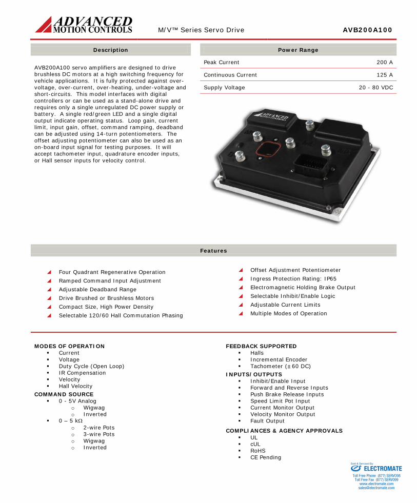
BLOCK DIAGRAM
POT1
VARIABLERC-BLOCK
LOOP INTEGRATORVELOCITY CURRENT LOOP
POT6
POT3
SW2-
3 POT5
SW2-
1
SW2-
2
SW1-1POT4
SW1-4 SW1-5SW1-3
20k10k..310k
CW
-+
10K
-+20.8k
PWM ANDCONTROL
LOGIC
10nF
SW1-
2
SW1-7
Peak/Cont.CURRENT
LIMIT100k
P1-5PGND
SW3-1..5
5nF..82nF
CF1*SW3-6..10
DC-TO-DC
SW1-9
COMMANDLIMITER
RAMP
+5VI
SW2-4
DEADBANDCW
10K
10k
-+
CW
5k
20k
+5VI
P1-12 INH/ENABLE
5k
100k
+5V
-5V
10k
HALL/ENCCONV.
10k
10k
OFF
INPUT COMMAND SELECTION
OFFONWIG-WAG INPUT DIRECTION
2-WIRE POTENTIOMETER
SW2
SINGLE INPUT DIRECTION1
OFFON
ONOFFON
4 FULL SPEED REVERSESTANDARD INPUT
HALF SPEED REVERSE
2 3-WIRE POTENTIOMETERINVERTED INPUT3
10k
P1-1
5
P1-2
0
P1-1
3
P1-1
4
P1-2
110K
P1-1
9
10k
SW1-
8
SW1-
6
SENSECURRENT
CURRENTMONITOR
INTERNAL
CONVERTERDC-TO-DC
P1-1
7
OFF
N/AON
OFFOFF
ON
N/A
ONON
OFFOFFOFF
P1-2
3
P1-7
P1-2
2
P1-8
10k 10k
Q22222
20k
+5VI+5VI
50k
HVI
N
BRAKE RF2
*
LIMITCW
U31
OFF=60ON=120
U34
RF1* IR-COMPENSATION
POT2
MOTOR A MAINH SEL
H-BRIDGEH1,H2,H3MCMOTOR C
3-Phase MOTOR B MB
DEG ENC A,B
2.2uF
CF2*
CURRENT100k
0.47uF
PGND
B+
B-
AVB200A100 FUNCTIONAL BLOCK DIAGRAM
KEYSWITCH P1-6
HVIN
SW1-10
CONVERSIONP1-1 THROTTLE INPUT
P1-16
P1-10
0 to +/-30%
SPEED/COMMAND LIMIT
FORWARD
REF IN LOOP GAINVELOCITY
OFF
ON U20
U32
OFFSET
TESTCW
Max: 1.8s/VMin: 0.1s/V
ENC A,B
+5VHE
H3
ENC
A
ENC
B
H2
H1
INH
/EN
ABLE
DC
-BU
S C
UR
REN
T
FAU
LT
VOLTAGE FEEDBACK
DRIVES ARE SHIPPED IN CURRENT MODE WITH MAXIMUM CURRENT SETTINGS
LED GREEN - NORMAL OPERATION, LED RED - FAULT
FOR OTHER SWITCH FUNCTIONS SEE SWITCH DESCRIPTION
RECOMMENDED SETTINGS FOR CURRENT MODE - POT1 FULLY CCW, POT3 FULLY CW
* OPTIONAL USER INSTALLED THROUGH HOLE COMPONENTS
DUTY CYCLE FEEDBACK
MO
NIT
OR
H1,H2,H3
VELOCITY MODE SELECTOR
+5VHE
CU
RR
ENT
LOO
P
OFF=VM VelD
ir
Cur
r/VelON=CM
CURRENT FEEDBACK
SW1-5SW1-4
VELO
CIT
Y M
ON
ITO
R
MODE SELECTION SW1-3
P1-3
POT-LOW (3mA)P1-4
OFFOFF
N/AOFF
N/A - NOT APPLICABLE
IR COMPENSATION**
X - DEPENDENT ON APPLICATION
OFF
ENCODER VELOCITY
CURRENT
VOLTAGE
HALL VELOCITY
DUTY CYCLE
BRAK
E O
UT
(3A)
TAC
H-IN
+5VH
E (2
50m
A)
BRAK
E R
ETU
RN
24V/
200H
z PW
M
X
XX
SW1-7
N/A
XON
OFFOFFOFF
SW1-6
OFF
OFFON
OFF
P1-2 SGND
REVERSEP1-11
POT-HIGH (3mA)
FAULT
FAULT-OUTP1-18
SGNDP1-9
DIRECTIONLOGIC
N/A N/ATACHOMETER ON XOFF** IR COMPENSATION MODE REQUIRES USER INSTALLED RESISTOR RF1 ON THE PCB
Information on Approvals and Compliances
US and Canadian safety compliance with UL 508c, the industrial standard for power conversion electronics. UL registered under file number E140173. Note that machine components compliant with UL are considered UL registered as opposed to UL listed as would be the case for commercial products.
RoHS (Reduction of Hazardous Substances) is intended to prevent hazardous substances such as lead from being manufactured in electrical and electronic equipment.
ELECTROMATEToll Free Phone (877) SERVO98
Toll Free Fax (877) SERV099www.electromate.com
Sold & Serviced By:
M/V™ Series Servo Drive AVB200A100
Release Date:
9/10/2013 Revision:
2.01 Advanced Motion Controls · 3805 Calle Tecate, Camarillo, CA, 93012
ph# 805-389-1935 · fx# 805-389-1165· www.a-m-c.com Page 3 of 12
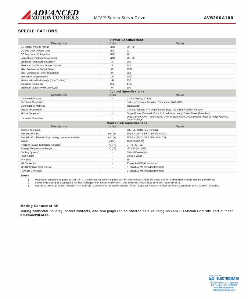
SPECIFICATIONS
Power Specifications Description Units Value
DC Supply Voltage Range VDC 20 - 80 DC Bus Over Voltage Limit VDC 92 DC Bus Under Voltage Limit VDC 16 Logic Supply Voltage (Keyswitch) VDC 20 - 80 Maximum Peak Output Current1 A 200 Maximum Continuous Output Current A 125 Max. Continuous Output Power W 9500 Max. Continuous Power Dissipation W 500 Internal Bus Capacitance µF 6000 Minimum Load Inductance (Line-To-Line) 2 µH 250 Switching Frequency kHz 14.6 Maximum Output PWM Duty Cycle % 100
Control Specifications Description Units Value
Command Sources - 0 - 5 V Analog, 0 - 5 kΩ Feedback Supported - Halls, Incremental Encoder, Tachometer (±60 VDC) Commutation Methods - Trapezoidal Modes of Operation - Current, Voltage, IR Compensation, Duty Cycle, Hall Velocity, Velocity Motors Supported - Single Phase (Brushed, Voice Coil, Inductive Load), Three Phase (Brushless)
Hardware Protection - Over Current, Over Temperature, Over Voltage, Short Circuit (Phase-Phase & Phase-Ground), Under Voltage
Mechanical Specifications Description Units Value
Agency Approvals - cUL, UL, RoHS, CE Pending Size (H x W x D) mm (in) 203.2 x 139.7 x 59.7 (8.0 x 5.5 x 2.4) Size (H x W x D) with 23-pin mating connector installed mm (in) 203.2 x 139.7 x 74.0 (8.0 x 5.5 x 2.9) Weight g (oz) 1638.60 (57.80) Heatsink (Base) Temperature Range3 °C (°F) 0 - 75 (32 - 167) Storage Temperature Range °C (°F) -20 - 85 (-4 - 185) Cooling System3 - Natural Convection Form Factor - Vehicle Mount IP Rating - 65 I/O Connector - 23-pin, AMPSEAL connector MOTOR POWER Connector - 3 Individual M6 threaded terminals POWER Connector - 2 Individual M6 threaded terminals
Notes
1. Maximum duration of peak current is ~10 seconds for zero-to-peak current commands. Peak-to-peak current commands should not be performed. 2. Lower inductance is acceptable for bus voltages well below maximum. Use external inductance to meet requirements. 3. Additional cooling and/or heatsink is required to achieve rated performance. Thermal grease recommended between baseplate and external heatsink.
Mating Connector Kit Mating connector housing, socket contacts, and seal plugs can be ordered as a kit using ADVANCED Motion Controls’ part number KC-23AMPSEAL01.
ELECTROMATEToll Free Phone (877) SERVO98
Toll Free Fax (877) SERV099www.electromate.com
Sold & Serviced By:

M/V™ Series Servo Drive AVB200A100
Release Date:
9/10/2013 Revision:
2.01 Advanced Motion Controls · 3805 Calle Tecate, Camarillo, CA, 93012
ph# 805-389-1935 · fx# 805-389-1165· www.a-m-c.com Page 4 of 12
PIN FUNCTIONS
I/O - Signal Connector
Pin Name Description / Notes I/O 1 THROTTLE IN 0 – 5 V reference command input or 0 – 5 kΩ resistance command input. Do not perform
peak-to-peak current commands. I
2 SIGNAL GROUND SGND
3 POT HIGH +5V @ 3 mA. For customer use. Reference to Signal Ground. Becomes disabled when 2-wire pot command is selected (SW2-2 = OFF) O
4 POT LOW Signal Ground. SGND 5 POWER GROUND Power Ground PGND
6 KEYSWITCH Master switch for the drive. Logic power input supply. Voltage range equal to DC Supply Voltage Range (see specifications table). This must be ON for the drive to function. Reference to Power Ground.
I
7 BRAKE Brake Output. This output will energize when the Keyswitch is ON and the drive is enabled. Outputs up to 24V, 3A max. Reference to Brake Return. O
8 BRAKE RETURN Brake Return I 9 SIGNAL GROUND Signal Ground SGND
10 FORWARD When not in Wigwag mode, with only one input active at a time, Forward and Reverse inputs selects the direction of motion. Pull low (Signal Ground) to activate. When the drive is disabled or faulted, activating both Pins at the same time will energize Brake Output (Pin7). Activating only one input when the drive is disabled or faulted will not energize Brake Output.
I
11 REVERSE I
12 INHIBIT/ENABLE This TTL level input signal turns off all power devices of the “H” bridge when pulled to Signal Ground with SW1-9=ON. If SW1-9=OFF, pulling this pin to Signal Ground will enable the drive.
I
13 HALL 1 Hall sensor inputs. Logic levels: maximum low level input is 1.5 VDC, minimum high level input is 3.5 VDC. Reference to Power Ground.
I 14 HALL 2 I 15 HALL 3 I
16 SPEED/COMMAND LIMIT Sets the maximum speed/command limit (command type dependent on the mode of operation). Voltage value at this pin will act as the upper limit available for the throttle input command
I
17 VELOCITY MONITOR 1V = 21.5 kHz Encoder Frequency; 1V = 100 Hz Hall Sensor Frequency. Reference to Power Ground. O
18 FAULT OUT
This output activates during short circuit, over-voltage, under voltage, inhibit, over-temperature and power-on reset. A red LED also indicates a fault condition. Reference to Signal Ground. Can be used with an external voltage supply and LED for visual fault indication.
O
19 DC BUS CURRENT MONITOR Scaling factor = 27.4 A/V. This output represents the actual power supply DC Bus current. Reference to Power Ground. O
20 ENCODER A Encoder Channel A. Reference to Power Ground. I 21 ENCODER B Encoder Channel B. Reference to Power Ground. I 22 +5V OUT +5V @ 150mA. For customer use. Reference to Power Ground. O 23 TACH Tachometer Input, 60k ohm input resistance, ± 60 V max. Reference to Power Ground. I
MOTOR POWER - Power Connector
Terminal Name Description / Notes I/O MA MOTOR A Motor Phase A O MB MOTOR B Motor Phase B O MC MOTOR C Motor Phase C O
POWER - Power Connector
Terminal Name Description / Notes I/O B- BATT - / POWER GROUND Power Ground PGND B+ BATT + DC Power Input. Battery Power. I
ELECTROMATEToll Free Phone (877) SERVO98
Toll Free Fax (877) SERV099www.electromate.com
Sold & Serviced By:
M/V™ Series Servo Drive AVB200A100
Release Date:
9/10/2013 Revision:
2.01 Advanced Motion Controls · 3805 Calle Tecate, Camarillo, CA, 93012
ph# 805-389-1935 · fx# 805-389-1165· www.a-m-c.com Page 5 of 12
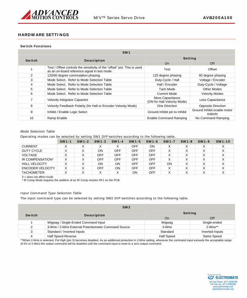
HARDWARE SETTINGS
Switch Functions
SW1
Switch Description Setting On Off
1 Test / Offset controls the sensitivity of the “offset” pot. This is used as an on-board reference signal in test mode. Test Offset
2 120/60 degree commutation phasing. 120 degree phasing 60 degree phasing 3 Mode Select. Refer to Mode Selection Table Duty-Cycle / Hall Voltage / Encoder 4 Mode Select. Refer to Mode Selection Table Hall / Encoder Duty-Cycle / Voltage 5 Mode Select. Refer to Mode Selection Table Tach Mode Other Modes 6 Mode Select. Refer to Mode Selection Table Current Mode Velocity Modes
7 Velocity Integrator Capacitor More Capacitance (ON for Hall Velocity Mode) Less Capacitance
8 Velocity Feedback Polarity (for Hall or Encoder Velocity Mode) One Direction Opposite Direction
9 Inhibit / Enable Logic Select Ground Inhibit pin to Inhibit Ground Inhibit enable motor outputs
10 Ramp Enable Enable Command Ramping No Command Ramping
Mode Selection Table Operating modes can be selected by setting SW1 DIP switches according to the following table. Mode SW1-1 SW1-2 SW1-3 SW1-4 SW1-5 SW1-6 SW1-7 SW1-8 SW1-9 SW1-10 CURRENT X X X X OFF ON X X X X DUTY CYCLE X X ON OFF OFF OFF X X X X VOLTAGE X X OFF OFF OFF OFF X X X X IR COMPENSATION* X X OFF OFF OFF OFF X X X X HALL VELOCITY X X ON ON OFF OFF ON X X X ENCODER VELOCITY X X OFF ON OFF OFF X X X X TACHOMETER X X X X ON OFF X X X X X = does not affect mode * IR Comp Mode requires the addition of an IR Comp resistor RF1 on the PCB.
Input Command Type Selection Table The input command type can be selected by setting SW2 DIP switches according to the following table.
SW2
Switch Description Setting On Off
1 Wigwag / Single-Ended Command Input Wigwag Single-ended 2 3-Wire / 2-Wire External Potentiometer Command Source 3-Wire 2-Wire** 3 Standard / Inverted Inputs Standard Inverted Inputs 4 Half Speed Reverse Half Speed Same Speed
**When 2-Wire is selected, Pot High (pin 3) becomes disabled. As an additional protection in 2-Wire setting, whenever the command input exceeds the acceptable range (0-5V or 0-5kΩ) the output command will be disabled until the command input is reset to a zero output command.
ELECTROMATEToll Free Phone (877) SERVO98
Toll Free Fax (877) SERV099www.electromate.com
Sold & Serviced By:
M/V™ Series Servo Drive AVB200A100
Release Date:
9/10/2013 Revision:
2.01 Advanced Motion Controls · 3805 Calle Tecate, Camarillo, CA, 93012
ph# 805-389-1935 · fx# 805-389-1165· www.a-m-c.com Page 6 of 12
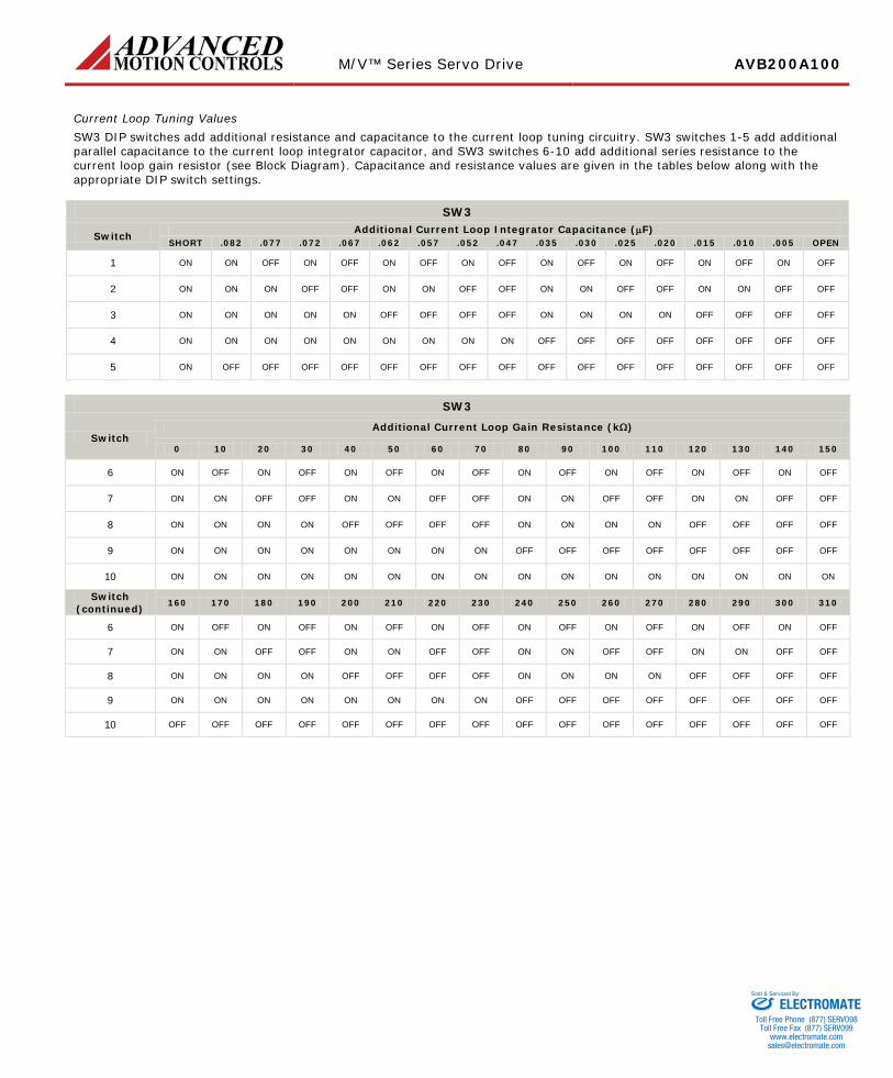
Current Loop Tuning Values SW3 DIP switches add additional resistance and capacitance to the current loop tuning circuitry. SW3 switches 1-5 add additional parallel capacitance to the current loop integrator capacitor, and SW3 switches 6-10 add additional series resistance to the current loop gain resistor (see Block Diagram). Capacitance and resistance values are given in the tables below along with the appropriate DIP switch settings.
SW3
Switch Additional Current Loop Integrator Capacitance (µF) SHORT .082 .077 .072 .067 .062 .057 .052 .047 .035 .030 .025 .020 .015 .010 .005 OPEN
1 ON ON OFF ON OFF ON OFF ON OFF ON OFF ON OFF ON OFF ON OFF
2 ON ON ON OFF OFF ON ON OFF OFF ON ON OFF OFF ON ON OFF OFF
3 ON ON ON ON ON OFF OFF OFF OFF ON ON ON ON OFF OFF OFF OFF
4 ON ON ON ON ON ON ON ON ON OFF OFF OFF OFF OFF OFF OFF OFF
5 ON OFF OFF OFF OFF OFF OFF OFF OFF OFF OFF OFF OFF OFF OFF OFF OFF
SW3
Switch Additional Current Loop Gain Resistance (kΩ)
0 10 20 30 40 50 60 70 80 90 100 110 120 130 140 150
6 ON OFF ON OFF ON OFF ON OFF ON OFF ON OFF ON OFF ON OFF
7 ON ON OFF OFF ON ON OFF OFF ON ON OFF OFF ON ON OFF OFF
8 ON ON ON ON OFF OFF OFF OFF ON ON ON ON OFF OFF OFF OFF
9 ON ON ON ON ON ON ON ON OFF OFF OFF OFF OFF OFF OFF OFF
10 ON ON ON ON ON ON ON ON ON ON ON ON ON ON ON ON
Switch (continued) 160 170 180 190 200 210 220 230 240 250 260 270 280 290 300 310
6 ON OFF ON OFF ON OFF ON OFF ON OFF ON OFF ON OFF ON OFF
7 ON ON OFF OFF ON ON OFF OFF ON ON OFF OFF ON ON OFF OFF
8 ON ON ON ON OFF OFF OFF OFF ON ON ON ON OFF OFF OFF OFF
9 ON ON ON ON ON ON ON ON OFF OFF OFF OFF OFF OFF OFF OFF
10 OFF OFF OFF OFF OFF OFF OFF OFF OFF OFF OFF OFF OFF OFF OFF OFF
ELECTROMATEToll Free Phone (877) SERVO98
Toll Free Fax (877) SERV099www.electromate.com
Sold & Serviced By:
M/V™ Series Servo Drive AVB200A100
Release Date:
9/10/2013 Revision:
2.01 Advanced Motion Controls · 3805 Calle Tecate, Camarillo, CA, 93012
ph# 805-389-1935 · fx# 805-389-1165· www.a-m-c.com Page 7 of 12
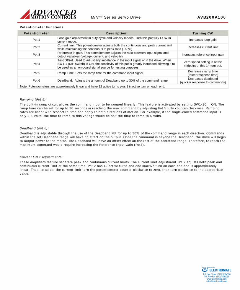
Potentiometer Functions
Potentiometer Description Turning CW
Pot 1 Loop gain adjustment in duty cycle and velocity modes. Turn this pot fully CCW in current mode. Increases loop gain
Pot 2 Current limit. This potentiometer adjusts both the continuous and peak current limit while maintaining the continuous to peak ratio (~63%). Increases current limit
Pot 3 Reference in gain. This potentiometer adjusts the ratio between input signal and output variables (voltage, current, and velocity). Increases reference input gain
Pot 4 Test/Offset. Used to adjust any imbalance in the input signal or in the drive. When SW1-1 (DIP switch) is ON, the sensitivity of this pot is greatly increased allowing it to be used as an on-board signal source for testing purposes.
Zero speed setting is at the midpoint of this 14-turn pot.
Pot 5 Ramp Time. Sets the ramp time for the command input signal. Decreases ramp time (faster response time)
Pot 6 Deadband. Adjusts the amount of Deadband up to 30% of the command range. Decreases deadband (quicker response to commands)
Note: Potentiometers are approximately linear and have 12 active turns plus 1 inactive turn on each end.
Ramping (Pot 5): The built-in ramp circuit allows the command input to be ramped linearly. This feature is activated by setting SW1-10 = ON. The ramp time can be set for up to 20 seconds in reaching the max command by adjusting Pot 5 fully counter-clockwise. Ramping rates are linear with respect to time and apply to both directions of motion. For example, if the single-ended command input is only 2.5 Volts, the time to ramp to this voltage would be half the time to ramp to 5 Volts.
Deadband (Pot 6): Deadband is adjustable through the use of the Deadband Pot for up to 30% of the command range in each direction. Commands within the set Deadband range will have no effect on the output. Once the command is beyond the Deadband, the drive will begin to output power to the motor. The Deadband will have an offset effect on the rest of the command range. Therefore, to reach the maximum command would require increasing the Reference Input Gain (Pot3).
Current Limit Adjustments: These amplifiers feature separate peak and continuous current limits. The current limit adjustment Pot 2 adjusts both peak and continuous current limit at the same time. Pot 2 has 12 active turns and one inactive turn on each end and is approximately linear. Thus, to adjust the current limit turn the potentiometer counter-clockwise to zero, then turn clockwise to the appropriate value.
ELECTROMATEToll Free Phone (877) SERVO98
Toll Free Fax (877) SERV099www.electromate.com
Sold & Serviced By:
M/V™ Series Servo Drive AVB200A100
Release Date:
9/10/2013 Revision:
2.01 Advanced Motion Controls · 3805 Calle Tecate, Camarillo, CA, 93012
ph# 805-389-1935 · fx# 805-389-1165· www.a-m-c.com Page 8 of 12
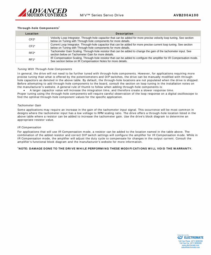
Through-hole Components†
Location Description
CF2* Velocity Loop Integrator. Through-hole capacitor that can be added for more precise velocity loop tuning. See section below on Tuning with Through-hole components for more details.
CF1* Current Loop Integrator. Through-hole capacitor that can be added for more precise current loop tuning. See section below on Tuning with Through-hole components for more details.
RF2* Tachometer Gain Scaling. Through-hole resistor that can be added to change the gain of the tachometer input. See section below on Tachometer Gain for more details.
RF1* IR Compensation Scaling. Through-hole resistor that can be added to configure the amplifier for IR Compensation mode. See section below on IR Compensation Notes for more details.
Tuning With Through-hole Components In general, the drive will not need to be further tuned with through-hole components. However, for applications requiring more precise tuning than what is offered by the potentiometers and DIP switches, the drive can be manually modified with through-hole capacitors as denoted in the above table. By default, the through-hole locations are not populated when the drive is shipped. Before attempting to add through-hole components to the board, consult the section on loop tuning in the installation notes on the manufacturer’s website. A general rule of thumb to follow when adding through-hole components is:
• A larger capacitor value will increase the integration time, and therefore create a slower response time. Proper tuning using the through-hole components will require careful observation of the loop response on a digital oscilloscope to find the optimal through-hole component values for the specific application.
Tachometer Gain Some applications may require an increase in the gain of the tachometer input signal. This occurrence will be most common in designs where the tachometer input has a low voltage to RPM scaling ratio. The drive offers a through-hole location listed in the above table where a resistor can be added to increase the tachometer gain. Use the drive’s block diagram to determine an appropriate resistor value.
IR Compensation For applications that will use IR Compensation mode, a resistor can be added to the location named in the table above. The combination of the added resistor and correct DIP switch settings will configure the amplifier for IR Compensation mode. While in IR Compensation mode, the amplifier will adjust the duty cycle to compensate for changes in the output current. Consult the amplifier’s functional block diagram and the manufacturer’s website for more information. †NOTE: DAMAGE DONE TO THE DRIVE WHILE PERFORMING THESE MODIFICATIONS WILL VOID THE WARRANTY.
ELECTROMATEToll Free Phone (877) SERVO98
Toll Free Fax (877) SERV099www.electromate.com
Sold & Serviced By:

M/V™ Series Servo Drive AVB200A100
Release Date:
9/10/2013 Revision:
2.01 Advanced Motion Controls · 3805 Calle Tecate, Camarillo, CA, 93012
ph# 805-389-1935 · fx# 805-389-1165· www.a-m-c.com Page 9 of 12
MECHANICAL INFORMATION
I/O - Signal Connector Connector Information 23-pin, AMPSEAL connector
Mating Connector Details TE Connectivity: Housing P/N 770680-1; Socket Contacts P/N 770854-3 (loose); Seal Plug P/N
770678-1; Crimp Tool P/N 58529-1 Included with Drive No
1THROTTLE IN 15 HALL 3
16SPEED/COMMAND LIMIT
2SIGNAL GROUND3POT HIGH
4POT LOW5POWER GROUND
6KEYSWITCH7BRAKE
8BRAKE RETURN
14 HALL 213 HALL 1
12 INHIBIT/ENABLE11 REVERSE
10 FORWARD9 SIGNAL GROUND
17VELOCITY MONITOR18FAULT OUT
19DC BUS CURRENT MONITOR20ENCODER A
21ENCODER B22+5V OUT
23TACH
MOTOR POWER - Power Connector
Connector Information Three individual M6 threaded terminal
Mating Connector Details M6 screw or bolt with washer
Included with Drive Yes
POWER - Power Connector Connector Information Two individual M6 threaded terminal
Mating Connector Details M6 screw or bolt with washer
Included with Drive Yes
ELECTROMATEToll Free Phone (877) SERVO98
Toll Free Fax (877) SERV099www.electromate.com
Sold & Serviced By:

M/V™ Series Servo Drive AVB200A100
Release Date:
9/10/2013 Revision:
2.01 Advanced Motion Controls · 3805 Calle Tecate, Camarillo, CA, 93012
ph# 805-389-1935 · fx# 805-389-1165· www.a-m-c.com Page 10 of 12
WIRING DIAGRAM
Motor
Encoder
Hall Sensors
Keyswitch Input
Keyswitch
Reverse
Forward
Inhibit
Brake Return
Main Contactor
Power Fuse
Control Fuse
Batt+
Batt- / Power GND
Brake
Motor A
Motor B
Motor C
Hall 1
*+5V SupplyHall 3Hall 2
Power GND
Encoder AEncoder B
*+5V Supply
Fault Out
EM Brake
Pot Low
Speed/Command Limit
Pot High
Battery 1
TachTach -
Tach Return / Power GND
Throttle Pot
Speed Limit Pot
Throttle Input
NOTE: All Feedback cannot be supported at one time
*+5V Supply is only one connection pin
ON board Status LED
Current Monitor or DC Bus Current
VUd
Current
Velocity Monitor
Isolation (on 200V drives)
Battery 2 or DC-DC Converter
Power GND
Keyswitch Relay
VUd
Speed
Chassis GND
Power GND
Fuse
Signal Ground
LED
+5VDC
500 ohm
ELECTROMATE
Toll Free Phone (877) SERVO98Toll Free Fax (877) SERV099
Sold & Serviced By:

M/V™ Series Servo Drive AVB200A100
Release Date:
9/10/2013 Revision:
2.01 Advanced Motion Controls · 3805 Calle Tecate, Camarillo, CA, 93012
ph# 805-389-1935 · fx# 805-389-1165· www.a-m-c.com Page 11 of 12
MOUNTING DIMENSIONS
ELECTROMATEToll Free Phone (877) SERVO98
Toll Free Fax (877) SERV099www.electromate.com
Sold & Serviced By:
M/V™ Series Servo Drive AVB200A100
Release Date:
9/10/2013 Revision:
2.01 Advanced Motion Controls · 3805 Calle Tecate, Camarillo, CA, 93012
ph# 805-389-1935 · fx# 805-389-1165· www.a-m-c.com Page 12 of 12
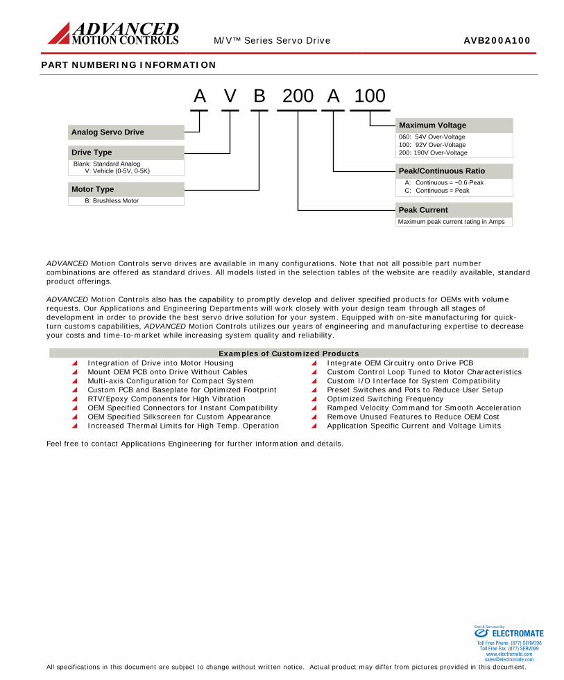
PART NUMBERING INFORMATION
A 100200
Peak CurrentBrushless MotorB:
Motor Type
Maximum peak current rating in Amps
V
Standard AnalogBlank:
Drive Type
V: Vehicle (0-5V, 0-5K)
A B
Peak/Continuous RatioContinuous = ~0.6·PeakA:Continuous = PeakC:
Maximum Voltage54V Over-Voltage060:92V Over-Voltage100:190V Over-Voltage200:
Analog Servo Drive
ADVANCED Motion Controls servo drives are available in many configurations. Note that not all possible part number combinations are offered as standard drives. All models listed in the selection tables of the website are readily available, standard product offerings. ADVANCED Motion Controls also has the capability to promptly develop and deliver specified products for OEMs with volume requests. Our Applications and Engineering Departments will work closely with your design team through all stages of development in order to provide the best servo drive solution for your system. Equipped with on-site manufacturing for quick-turn customs capabilities, ADVANCED Motion Controls utilizes our years of engineering and manufacturing expertise to decrease your costs and time-to-market while increasing system quality and reliability.
Examples of Customized Products Integration of Drive into Motor Housing Integrate OEM Circuitry onto Drive PCB Mount OEM PCB onto Drive Without Cables Custom Control Loop Tuned to Motor Characteristics Multi-axis Configuration for Compact System Custom I/O Interface for System Compatibility Custom PCB and Baseplate for Optimized Footprint Preset Switches and Pots to Reduce User Setup RTV/Epoxy Components for High Vibration Optimized Switching Frequency OEM Specified Connectors for Instant Compatibility Ramped Velocity Command for Smooth Acceleration OEM Specified Silkscreen for Custom Appearance Remove Unused Features to Reduce OEM Cost Increased Thermal Limits for High Temp. Operation Application Specific Current and Voltage Limits
Feel free to contact Applications Engineering for further information and details. All specifications in this document are subject to change without written notice. Actual product may differ from pictures provided in this document.
ELECTROMATEToll Free Phone (877) SERVO98
Toll Free Fax (877) SERV099www.electromate.com
Sold & Serviced By: