Embed Size (px)
Citation preview
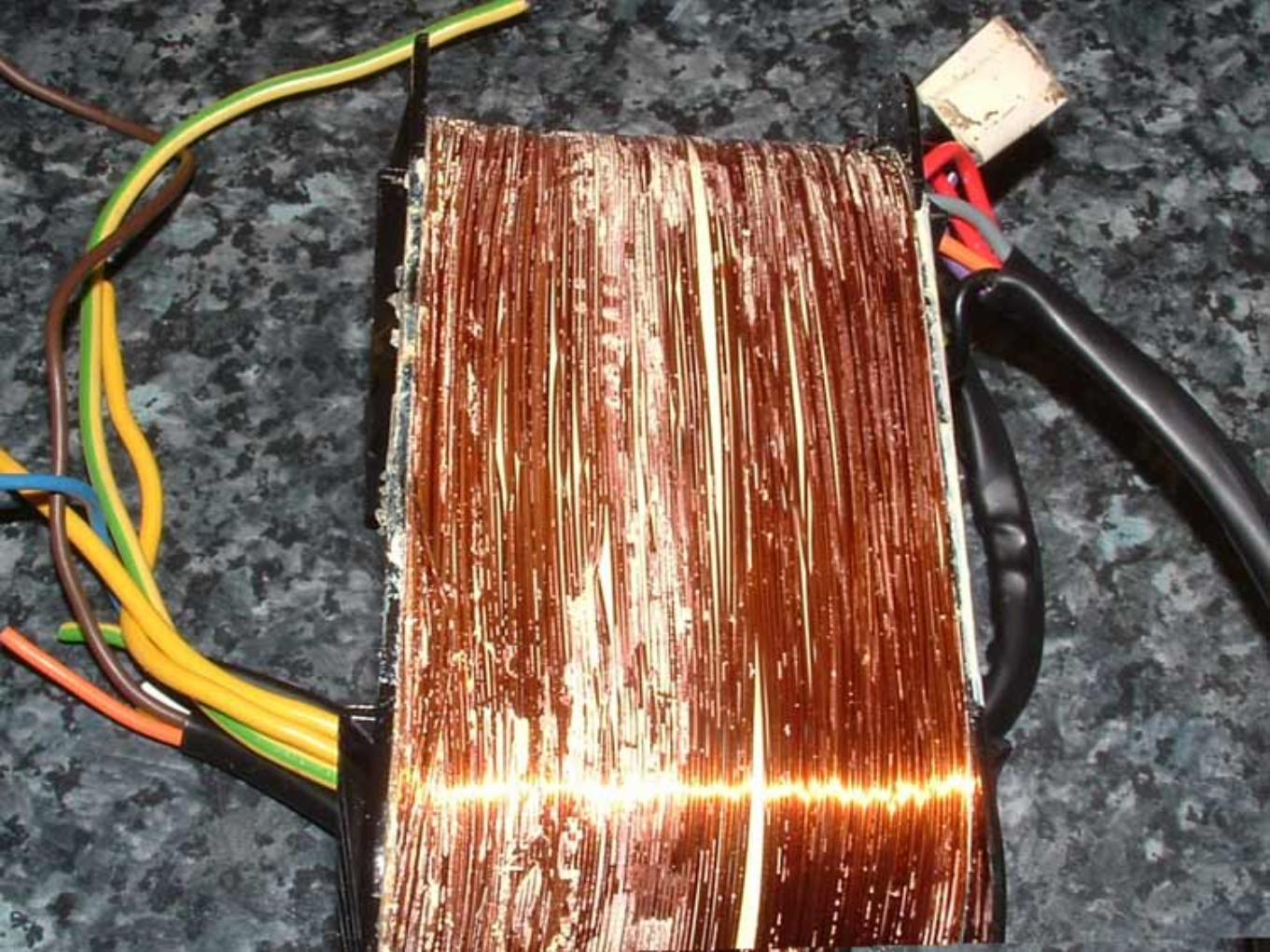
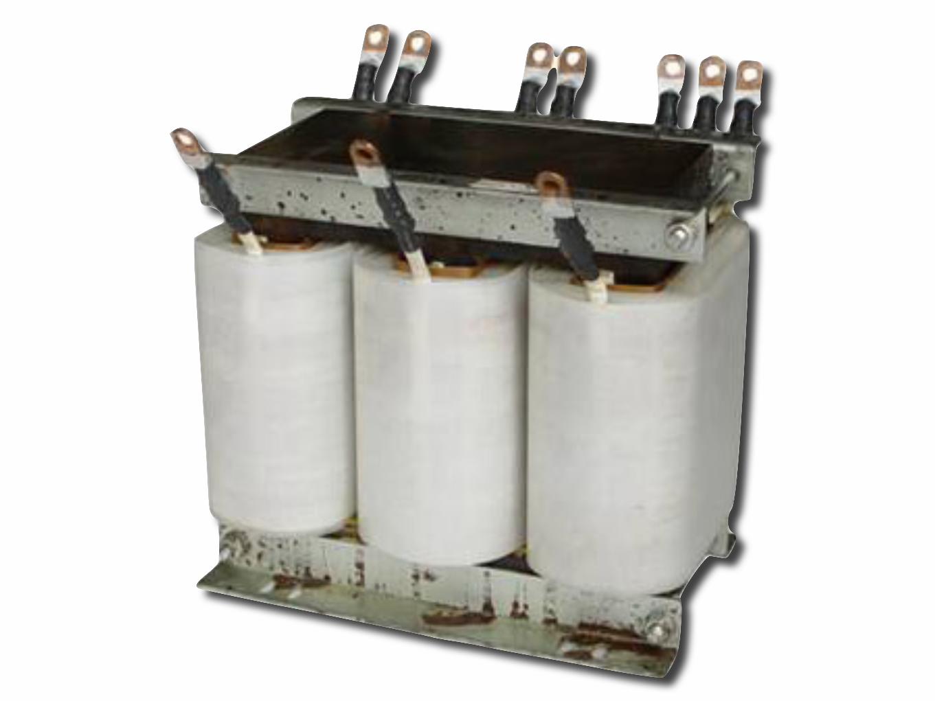
Combinations of transformer winding connectionsCombinations of transformer winding connectionsCombinations of transformer winding connections
Primary Secondary Common Uses
Star (Y) Star (Y) Industrial applications
Star (Y) Delta (∆) Commercial and industrial (most common method)
Delta (∆) Star (Y) High voltage transmissions
Delta (∆) Delta (∆) Rarely used - causes harmonics and balancing problems

10.5. THREE-PHASE Y AND ! CONFIGURATIONS 311
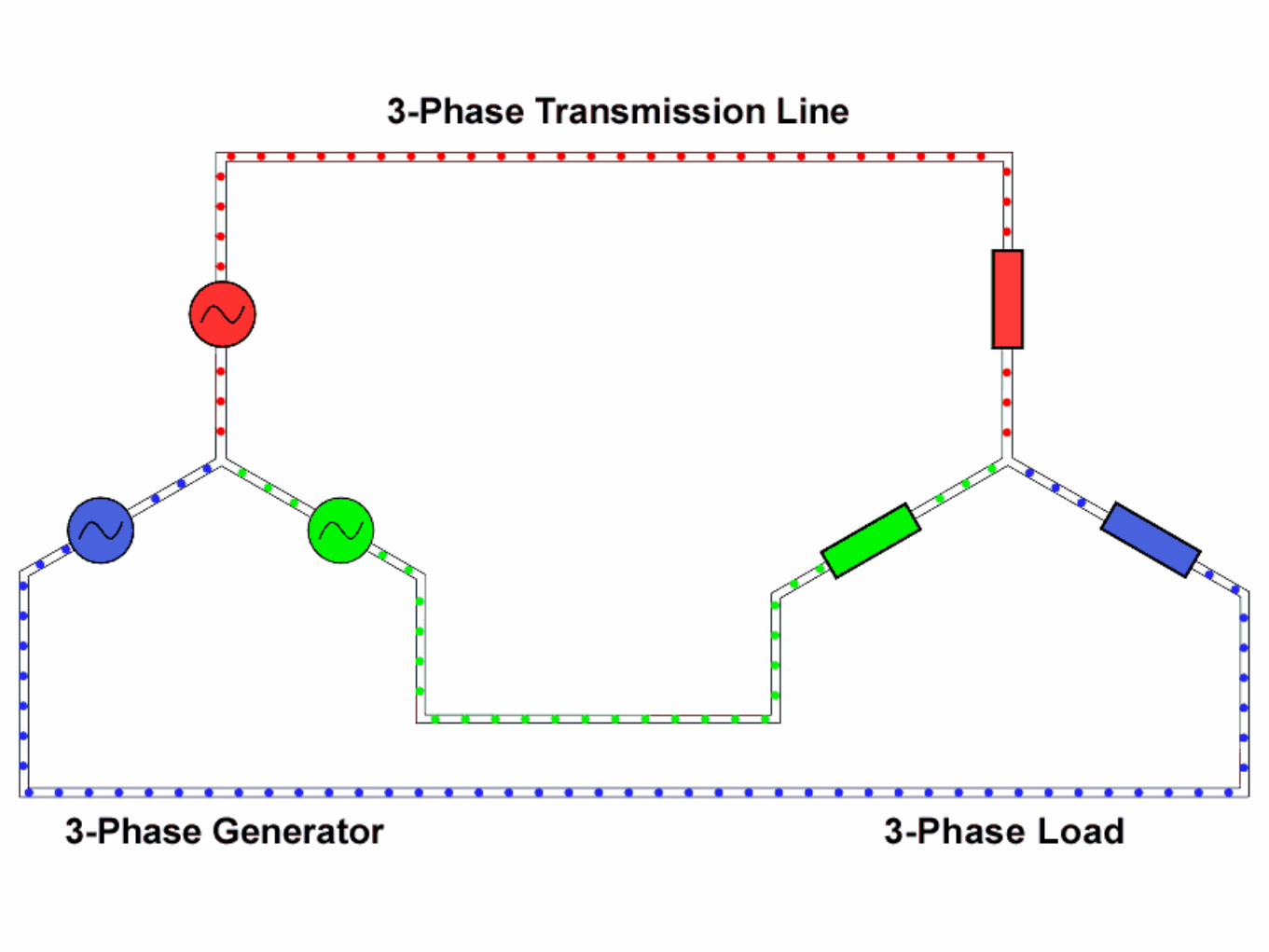
One distinct advantage of a !-connected system is its lack of a neutral wire. With a Y-connected system, a neutral wire was needed in case one of the phase loads were to fail open(or be turned off), in order to keep the phase voltages at the load from changing. This isnot necessary (or even possible!) in a !-connected circuit. With each load phase elementdirectly connected across a respective source phase winding, the phase voltage will be constantregardless of open failures in the load elements.Perhaps the greatest advantage of the !-connected source is its fault tolerance. It is pos-
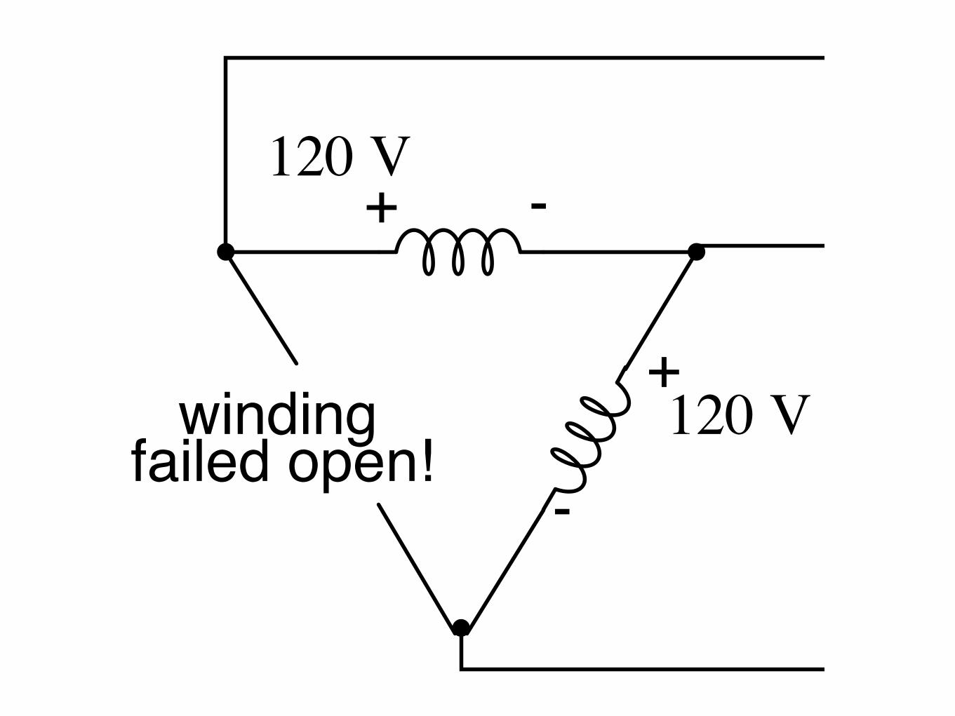
sible for one of the windings in a !-connected three-phase source to fail open (Figure 10.37)without affecting load voltage or current!
+ -
+
-
120 Vwindingfailed open!
120 V
120 V 120 V
120 V ! 0o
! 120o
Figure 10.37: Even with a source winding failure, the line voltage is still 120 V, and load phasevoltage is still 120 V. The only difference is extra current in the remaining functional sourcewindings.
The only consequence of a source winding failing open for a!-connected source is increasedphase current in the remaining windings. Compare this fault tolerance with a Y-connectedsystem suffering an open source winding in Figure 10.38.
+
-
+
-
120 V120 V
windingfailed open!
208 V
104 V 104 V! 0o
! 120o
Figure 10.38: Open “Y” source winding halves the voltage on two loads of a ! connected load.
With a !-connected load, two of the resistances suffer reduced voltage while one remainsat the original line voltage, 208. A Y-connected load suffers an even worse fate (Figure 10.39)with the same winding failure in a Y-connected sourceIn this case, two load resistances suffer reduced voltage while the third loses supply voltage
completely! For this reason, !-connected sources are preferred for reliability. However, if dualvoltages are needed (e.g. 120/208) or preferred for lower line currents, Y-connected systems are
!
!

314 CHAPTER 10. POLYPHASE AC CIRCUITS
Probably the most important aspect of connecting three sets of primary and secondary wind-ings together to form a three-phase transformer bank is paying attention to proper windingphasing (the dots used to denote “polarity” of windings). Remember the proper phase relation-ships between the phase windings of ! and Y: (Figure 10.41)
+
-
+
--
+
+ -
+
-
-
+
(Y)
! 0o
! 0o
! 120o
! 120o
! 240o ! 240
o
(")
Figure 10.41: (Y) The center point of the “Y” must tie either all the “-” or all the “+” windingpoints together. (!) The winding polarities must stack together in a complementary manner (+ to -).
Getting this phasing correct when the windings aren’t shown in regular Y or ! configura-tion can be tricky. Let me illustrate, starting with Figure 10.42.
T1 T2 T3
A1
B1
C1
A2
B2
C2
Figure 10.42: Inputs A1, A2, A3 may be wired either “!” or “Y”, as may outputs B1, B2, B3.
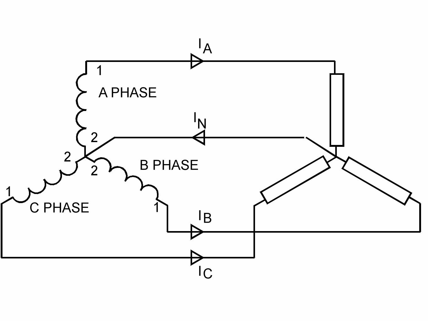
Three individual transformers are to be connected together to transform power from onethree-phase system to another. First, I’ll show the wiring connections for a Y-Y configuration:Figure 10.43Note in Figure 10.43 how all the winding ends marked with dots are connected to their
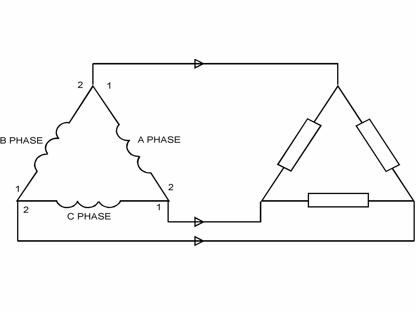
respective phases A, B, and C, while the non-dot ends are connected together to form the cen-ters of each “Y”. Having both primary and secondary winding sets connected in “Y” formationsallows for the use of neutral conductors (N1 and N2) in each power system.Now, we’ll take a look at a Y-! configuration: (Figure 10.44)Note how the secondary windings (bottom set, Figure 10.44) are connected in a chain, the
“dot” side of one winding connected to the “non-dot” side of the next, forming the ! loop. At
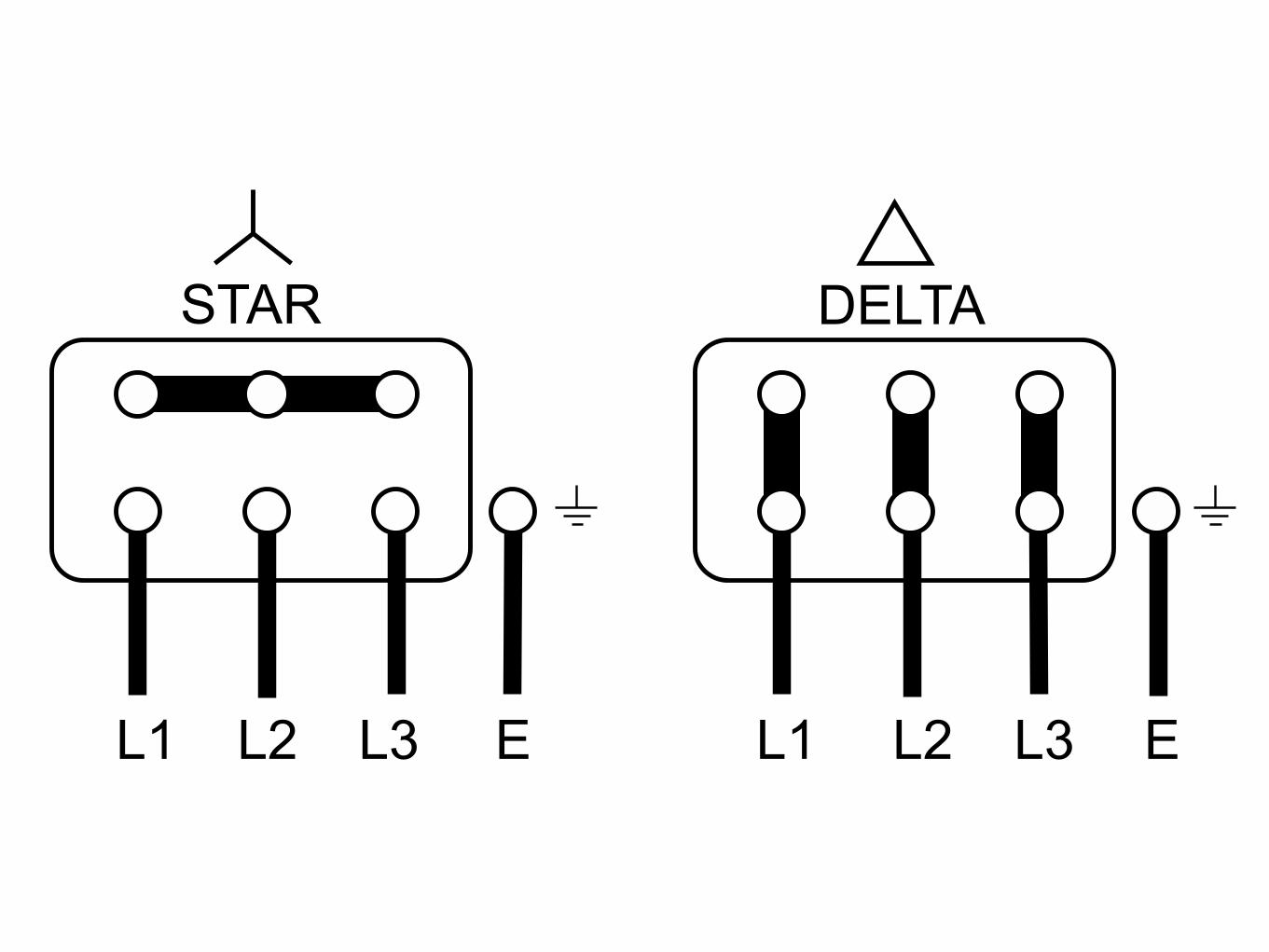
STAR and DELTA connection ofThree-phase Squirrel-cage Electric Motors
STAR DELTA
L1 L2 L3 E L1 L2 L3 ETo change direction of rotation swap any two Life (L1, L2, L3) inlet leads.
U V
WU1
U2 V1
V2
W1W2
U1 V1 W1
U2 V2W2
Connection when a STAR-DELTASTARTER is used. For connection ofthe six leads please follow instructionssupplied with your STARTER.
IMPORTANT ! Always check the motor nameplate for correct STAR (Y) and DELTA (D)voltage. Ask if in doubt !Incorrect wiring will damage the motor and invalidate the Warranty!
ROTOR (UK) LIMITED, 16 Everitt Close, Denington Industrial Estate, Wellingborough NN8 2QFTel 01933 230900 Fax 01933 272152 [email protected] www.rotor.co.uk