Embed Size (px)
Citation preview

I3C High Data Rate modes – from spec to real life devices
Alex Passi Sr. Principal Software Engineer
Cadence Design Systems
Introduction The MIPI Alliance I3C standardized sensor interface provides a number of significant advantages over existing digital sensor interfaces.
This paper will briefly present I3C interface basics and will focus on various verification aspects of I3C High Data Rate modes through an advanced verification methodology based on coverage driven verification and real-life scenarios
2
Single Data Rate Mode • Single Data Rate (SDR) Mode is the default mode used
by I3C
• I3C Bus always initializes in SDR Mode
• Maximum data rate – 12.5 Mbps
• SDR is almost similar to I2C, but introduces many new features not present in I2C
• SCL wire operates as a clock signal, while the data is transferred using SDA wire
3
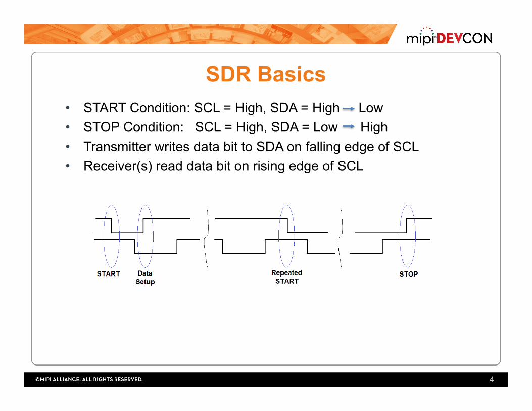
SDR Basics
4
• START Condition: SCL = High, SDA = High Low • STOP Condition: SCL = High, SDA = Low High • Transmitter writes data bit to SDA on falling edge of SCL • Receiver(s) read data bit on rising edge of SCL
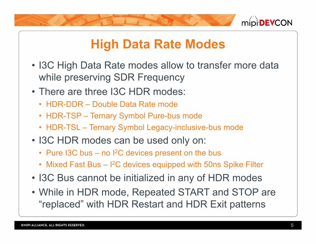
High Data Rate Modes • I3C High Data Rate modes allow to transfer more data
while preserving SDR Frequency • There are three I3C HDR modes:
• HDR-DDR – Double Data Rate mode • HDR-TSP – Ternary Symbol Pure-bus mode • HDR-TSL – Ternary Symbol Legacy-inclusive-bus mode
• I3C HDR modes can be used only on: • Pure I3C bus – no I2C devices present on the bus • Mixed Fast Bus – I2C devices equipped with 50ns Spike Filter
• I3C Bus cannot be initialized in any of HDR modes • While in HDR mode, Repeated START and STOP are
“replaced” with HDR Restart and HDR Exit patterns
5
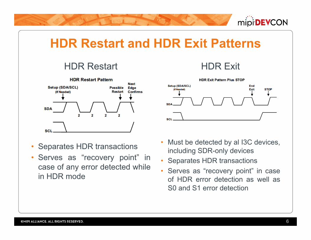
HDR Restart and HDR Exit Patterns
HDR Restart
• Separates HDR transactions • Serves as “recovery point” in
case of any error detected while in HDR mode
HDR Exit
• Must be detected by al I3C devices, including SDR-only devices
• Separates HDR transactions • Serves as “recovery point” in case
of HDR error detection as well as S0 and S1 error detection
6
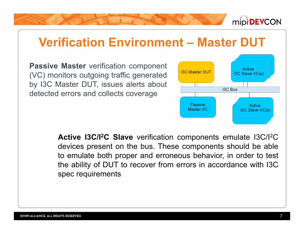
Verification Environment – Master DUT
Passive Master verification component (VC) monitors outgoing traffic generated by I3C Master DUT, issues alerts about detected errors and collects coverage
7
Active I3C/I2C Slave verification components emulate I3C/I2C devices present on the bus. These components should be able to emulate both proper and erroneous behavior, in order to test the ability of DUT to recover from errors in accordance with I3C spec requirements
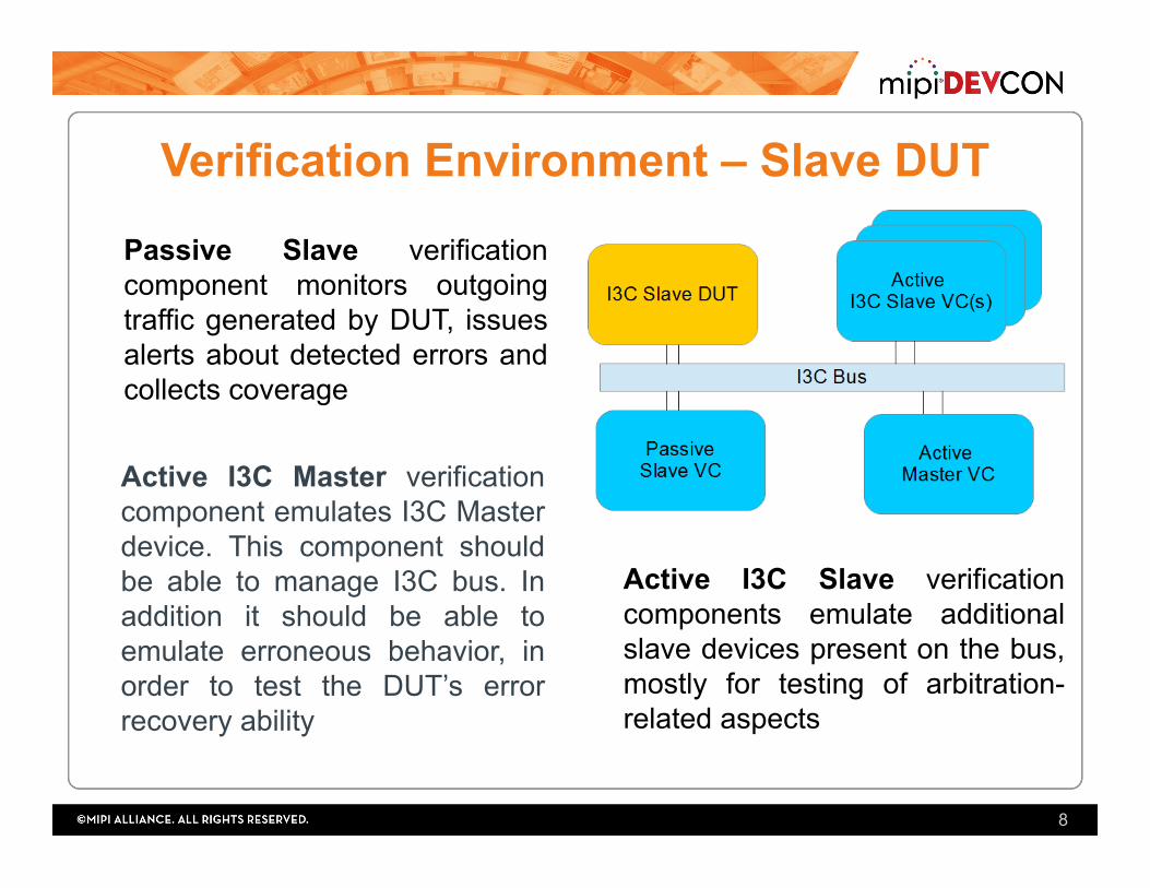
Verification Environment – Slave DUT
Active I3C Master verification component emulates I3C Master device. This component should be able to manage I3C bus. In addition it should be able to emulate erroneous behavior, in order to test the DUT’s error recovery ability
8
Passive Slave verification component monitors outgoing traffic generated by DUT, issues alerts about detected errors and collects coverage
Active I3C Slave verification components emulate additional slave devices present on the bus, mostly for testing of arbitration-related aspects
I3C HDR-DDR – Main Features • I3C Dual Data Rate (HDR-DDR) mode allows to increase
data rate up to 25 Mbps by reading data bits on both edges of SCL clock signal.
• The I3C Bus enters HDR-DDR mode upon transmission of ENTHDR0 Common Command Code and exits it when HDR Exit pattern is observed
• Data is transferred in messages that consist of Command Word, one or more Data Words and CRC Word
• Allows 128 Write commands and 64 Read commands
9
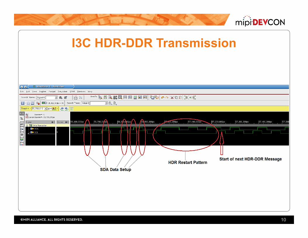
I3C HDR-DDR Transmission
10
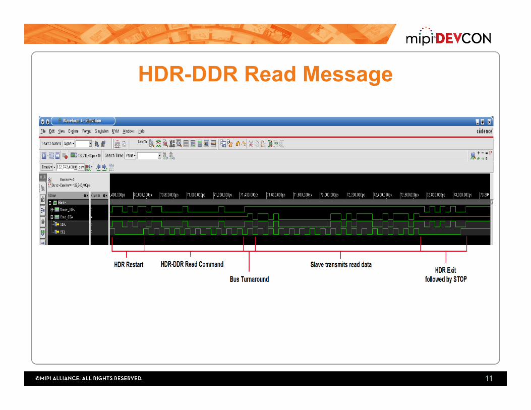
HDR-DDR Read Message
11
I3C HDR-DDR – Main Verification Points 1. “Invisibility” of HDR-DDR traffic to I2C devices present
on the bus
2. Correct encoding and decoding of data
3. Termination of Read operation by Master
4. Error detection and recovery
5. For designs not supporting HDR-DDR – proper ignoring of all HDR-DDR traffic
12
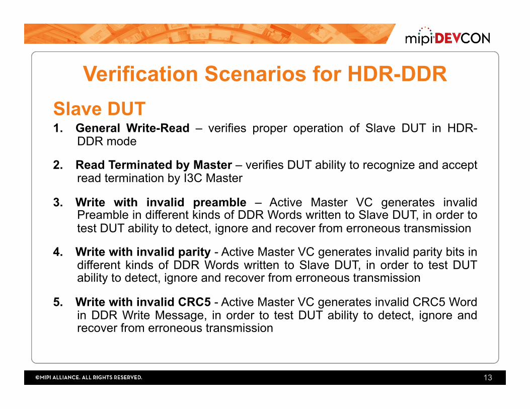
Verification Scenarios for HDR-DDR Slave DUT 1. General Write-Read – verifies proper operation of Slave DUT in HDR-
DDR mode
2. Read Terminated by Master – verifies DUT ability to recognize and accept read termination by I3C Master
3. Write with invalid preamble – Active Master VC generates invalid Preamble in different kinds of DDR Words written to Slave DUT, in order to test DUT ability to detect, ignore and recover from erroneous transmission
4. Write with invalid parity - Active Master VC generates invalid parity bits in different kinds of DDR Words written to Slave DUT, in order to test DUT ability to detect, ignore and recover from erroneous transmission
5. Write with invalid CRC5 - Active Master VC generates invalid CRC5 Word in DDR Write Message, in order to test DUT ability to detect, ignore and recover from erroneous transmission
13
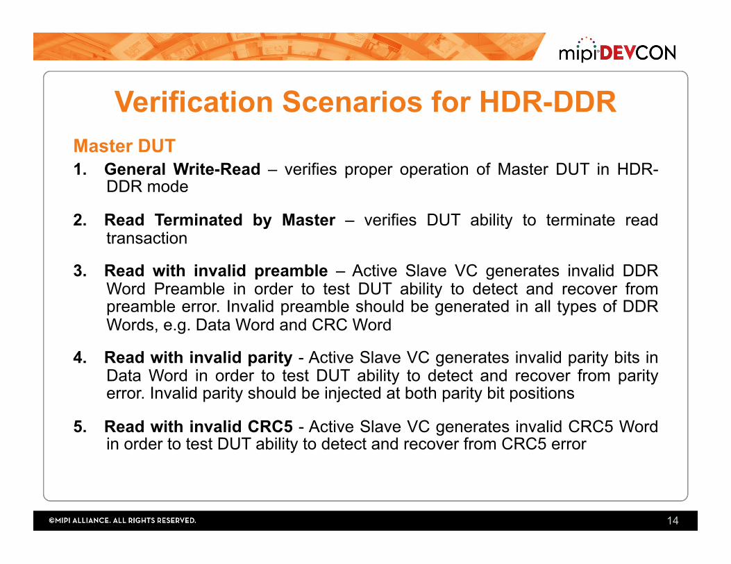
Verification Scenarios for HDR-DDR Master DUT 1. General Write-Read – verifies proper operation of Master DUT in HDR-
DDR mode
2. Read Terminated by Master – verifies DUT ability to terminate read transaction
3. Read with invalid preamble – Active Slave VC generates invalid DDR Word Preamble in order to test DUT ability to detect and recover from preamble error. Invalid preamble should be generated in all types of DDR Words, e.g. Data Word and CRC Word
4. Read with invalid parity - Active Slave VC generates invalid parity bits in Data Word in order to test DUT ability to detect and recover from parity error. Invalid parity should be injected at both parity bit positions
5. Read with invalid CRC5 - Active Slave VC generates invalid CRC5 Word in order to test DUT ability to detect and recover from CRC5 error
14
I3C HDR-TSP – Main Features • I3C Ternary Symbol for Pure Bus (HDR-TSP) mode allows to
increase significantly data rate by using both SDA and SCL wires for data transfer
• HDR-TSP is not allowed on mixed I3C-I2C bus
• The I3C Bus enters HDR-DDR mode upon transmission of ENTHDR1 Common Command Code and exits it when HDR Exit pattern is observed
• Data is transferred in messages that consist of Command Word and one or more Data Words
• Allows 128 Write commands and 64 Read commands
15
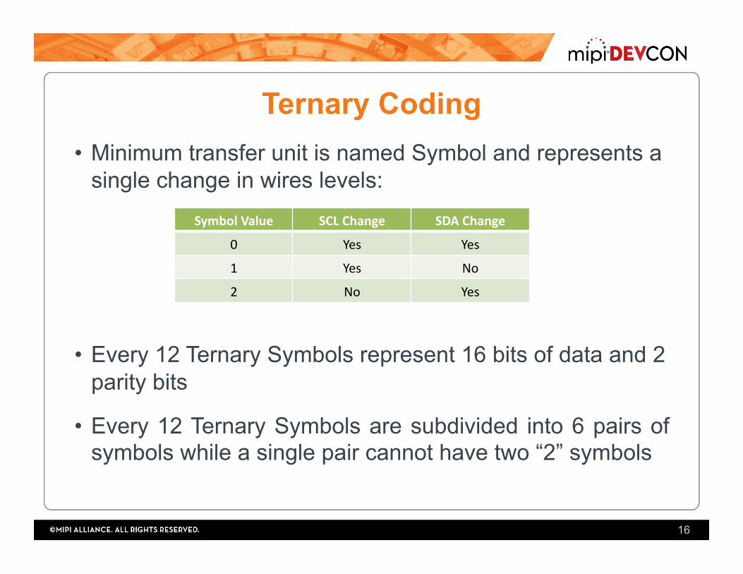
Ternary Coding • Minimum transfer unit is named Symbol and represents a
single change in wires levels:
• Every 12 Ternary Symbols represent 16 bits of data and 2 parity bits
• Every 12 Ternary Symbols are subdivided into 6 pairs of symbols while a single pair cannot have two “2” symbols
16
SymbolValue SCLChange SDAChange
0 Yes Yes
1 Yes No
2 No Yes
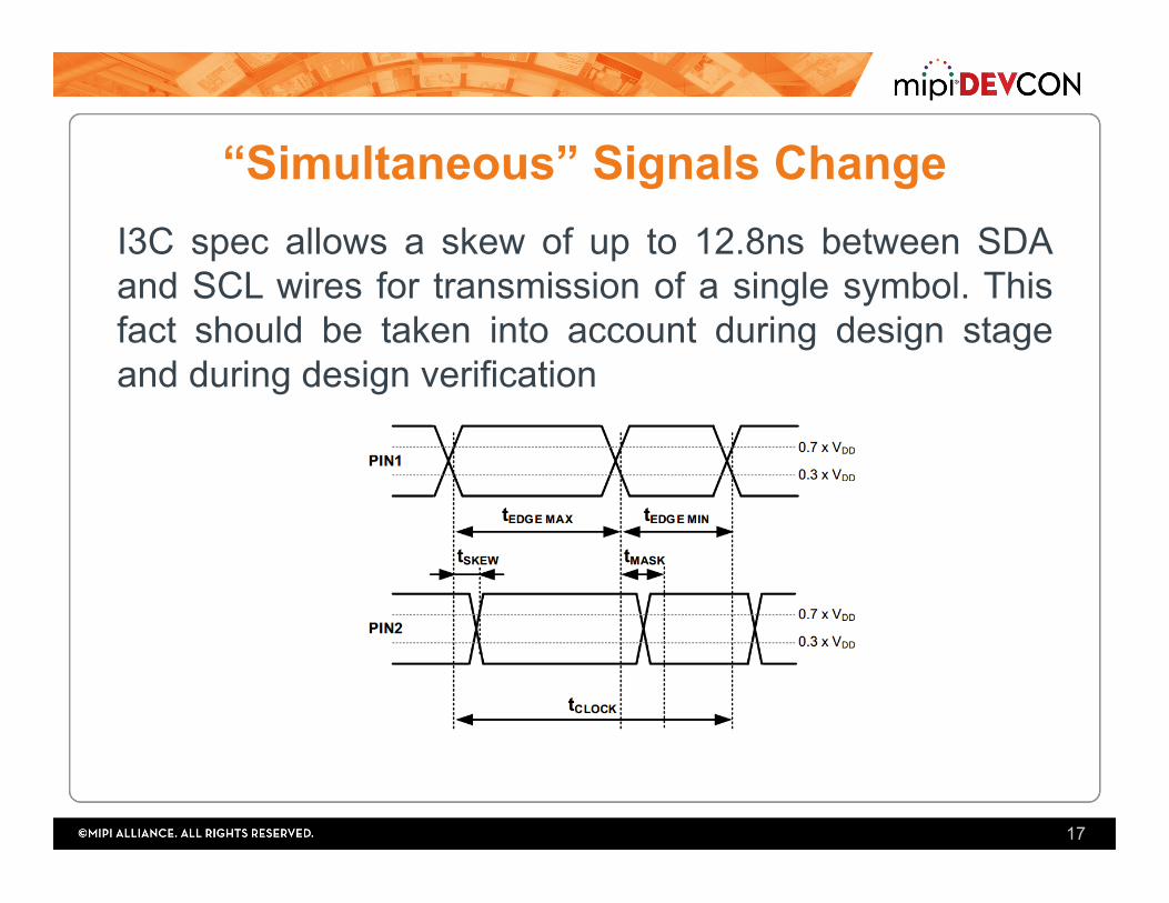
“Simultaneous” Signals Change I3C spec allows a skew of up to 12.8ns between SDA and SCL wires for transmission of a single symbol. This fact should be taken into account during design stage and during design verification
17

I3C HDR-TSP Message
18
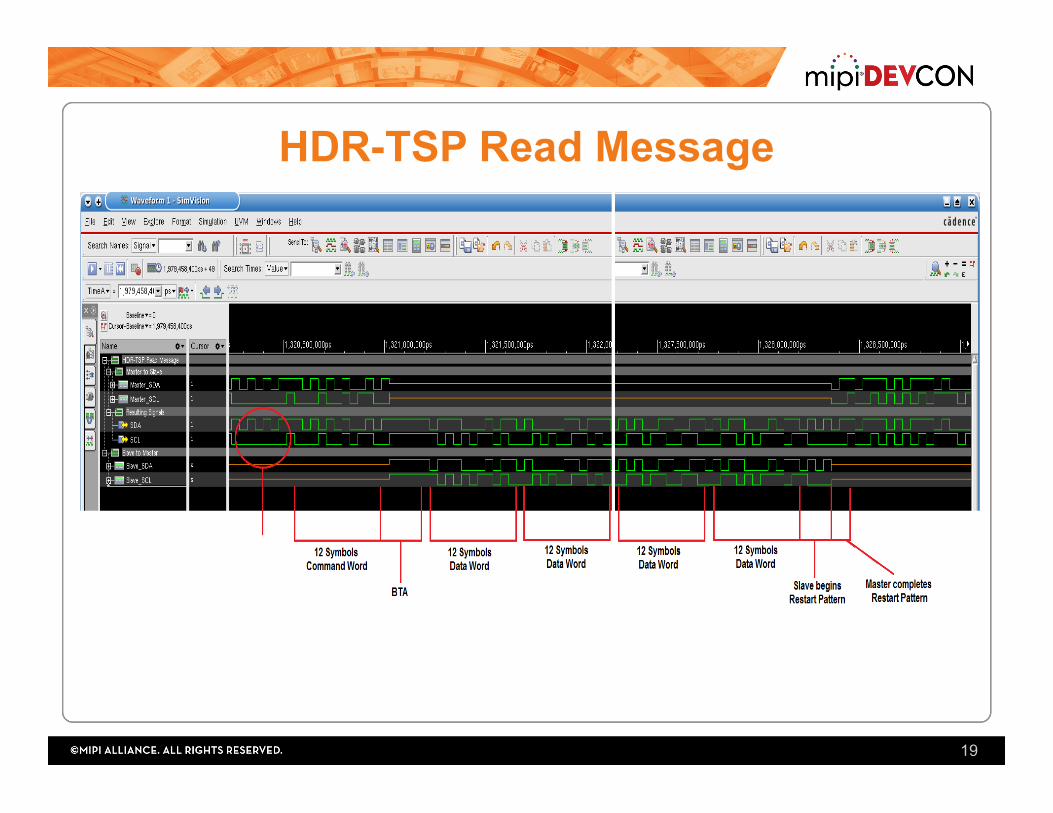
HDR-TSP Read Message
19
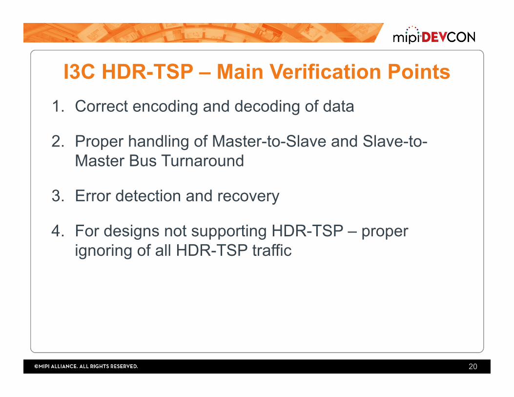
I3C HDR-TSP – Main Verification Points 1. Correct encoding and decoding of data
2. Proper handling of Master-to-Slave and Slave-to-Master Bus Turnaround
3. Error detection and recovery
4. For designs not supporting HDR-TSP – proper ignoring of all HDR-TSP traffic
20
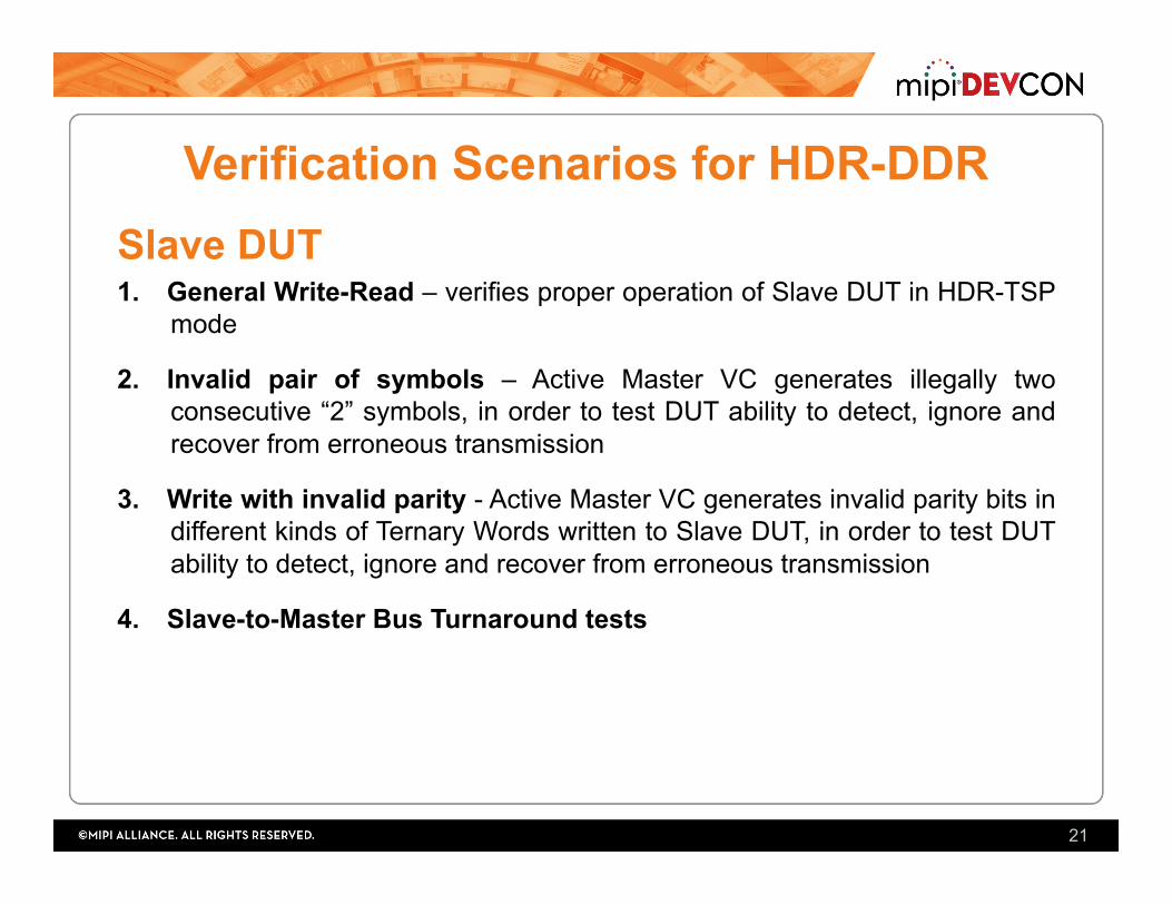
Verification Scenarios for HDR-DDR Slave DUT 1. General Write-Read – verifies proper operation of Slave DUT in HDR-TSP
mode
2. Invalid pair of symbols – Active Master VC generates illegally two consecutive “2” symbols, in order to test DUT ability to detect, ignore and recover from erroneous transmission
3. Write with invalid parity - Active Master VC generates invalid parity bits in different kinds of Ternary Words written to Slave DUT, in order to test DUT ability to detect, ignore and recover from erroneous transmission
4. Slave-to-Master Bus Turnaround tests
21
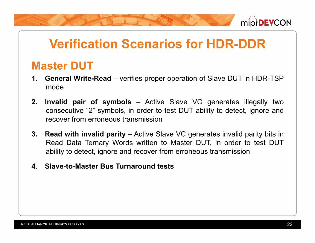
Verification Scenarios for HDR-DDR Master DUT 1. General Write-Read – verifies proper operation of Slave DUT in HDR-TSP
mode
2. Invalid pair of symbols – Active Slave VC generates illegally two consecutive “2” symbols, in order to test DUT ability to detect, ignore and recover from erroneous transmission
3. Read with invalid parity – Active Slave VC generates invalid parity bits in Read Data Ternary Words written to Master DUT, in order to test DUT ability to detect, ignore and recover from erroneous transmission
4. Slave-to-Master Bus Turnaround tests
22
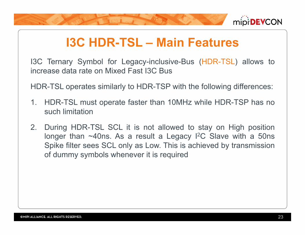
I3C HDR-TSL – Main Features I3C Ternary Symbol for Legacy-inclusive-Bus (HDR-TSL) allows to increase data rate on Mixed Fast I3C Bus
HDR-TSL operates similarly to HDR-TSP with the following differences:
1. HDR-TSL must operate faster than 10MHz while HDR-TSP has no such limitation
2. During HDR-TSL SCL it is not allowed to stay on High position longer than ~40ns. As a result a Legacy I2C Slave with a 50ns Spike filter sees SCL only as Low. This is achieved by transmission of dummy symbols whenever it is required
23
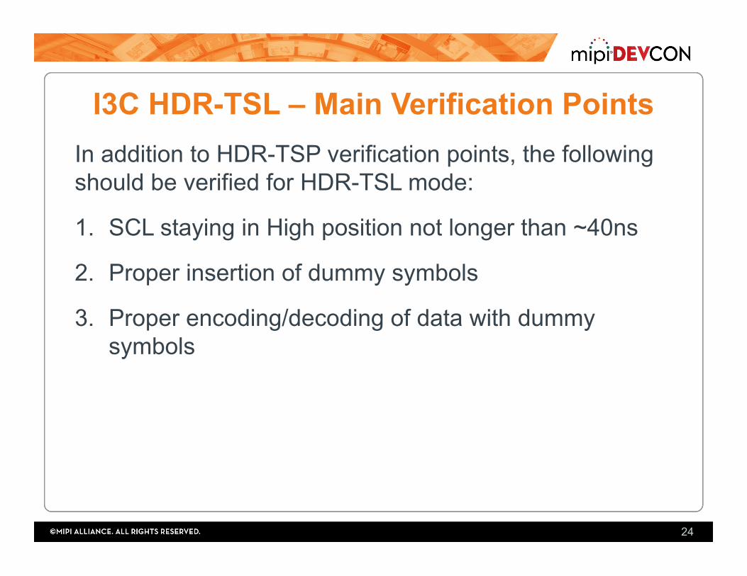
I3C HDR-TSL – Main Verification Points In addition to HDR-TSP verification points, the following should be verified for HDR-TSL mode:
1. SCL staying in High position not longer than ~40ns
2. Proper insertion of dummy symbols
3. Proper encoding/decoding of data with dummy symbols
24


![MIPI I3C Interface –Advanced Features...Delay Time [DT] in-band, via I3C bus ALL READ IN SYNC Sequence Repetition Period Adjustable [0.2 ; 5 sec], 1 sec nominal S equnc rpats T_Ph](https://img.dokumen.tips/doc/110x75/5fde1bbeaca105702d31fc2a/mipi-i3c-interface-aadvanced-features-delay-time-dt-in-band-via-i3c-bus.jpg)