Embed Size (px)
Citation preview
Griffith University
School of Computing and Information Technology
Domain: Modelling Languages
Business Modelling: UML vs. IDEF
available electronically at:
http://www.cit.gu.edu.au/~noran
© Ovidiu S. Noran
2000
© Ovidiu S. Noran Use of this document is permitted subject to proper reference to the author.
i
Table of Contents.
1 Introduction....................................................................................................1
1.1 The objectives of this paper. ..............................................................................1 1.2 Motivation...........................................................................................................1 1.3 Some Important Terms. .....................................................................................2
1.3.1 Models. .............................................................................................................. 2 1.3.2 Business Process Models.................................................................................. 2 1.3.3 Information Systems Support. ........................................................................... 3
1.3.3.1 The Business Model as a Base for Information Systems.......................... 3 1.3.3.2 'Legacy' Systems. ...................................................................................... 4
1.3.4 Business Improvement vs. Innovation............................................................... 4 1.4 Business Concepts. ...........................................................................................4
1.4.1 Business Architecture. ....................................................................................... 5 1.4.2 Business Rules. ................................................................................................. 5
1.4.2.1 Derivations................................................................................................. 5 1.4.2.2 Constraints................................................................................................. 5 1.4.2.3 Existence. .................................................................................................. 5
1.4.3 Business Views.................................................................................................. 5 1.4.3.1 Vision. ........................................................................................................ 6 1.4.3.2 Process...................................................................................................... 6 1.4.3.3 Structure. ................................................................................................... 6 1.4.3.4 Behaviour................................................................................................... 6
1.5 Software Architecture vs. Business Architecture. ..............................................6 1.5.1 Software Architecture. ....................................................................................... 7 1.5.2 Software Architectural Views. ............................................................................ 7 1.5.3 From Business To Software Architecture. ......................................................... 7
2 The Unified Modelling Language (UML). .......................................................9
2.1 Basics. ...............................................................................................................9 2.2 UML Diagrams. ..................................................................................................9
2.2.1 Class Diagram. .................................................................................................. 9 2.2.2 Object Diagram................................................................................................ 10 2.2.3 Statechart Diagram.......................................................................................... 10 2.2.4 Activity Diagram............................................................................................... 10 2.2.5 Sequence Diagram. ......................................................................................... 11 2.2.6 Collaboration Diagram. .................................................................................... 11 2.2.7 Use Case Diagram. ......................................................................................... 11 2.2.8 Component Diagram........................................................................................ 11 2.2.9 Deployment Diagram. ...................................................................................... 11
2.3 Extension Mechanisms. ...................................................................................12 2.3.1 Stereotypes...................................................................................................... 12 2.3.2 Tagged Values................................................................................................. 12 2.3.3 Constraints....................................................................................................... 12
2.4 Business Modelling with UML. .........................................................................12 2.4.1 Components of UML used in Business Modelling. .......................................... 13 2.4.2 Business Rules. ............................................................................................... 13 2.4.3 The Eriksson-Penker Business Extensions..................................................... 13 2.4.4 Business Patterns............................................................................................ 14
3 The IDEF Family of Languages. ..................................................................16
3.1 Basics. .............................................................................................................16 3.2 IDEF0...............................................................................................................16 3.3 IDEF1 / IDEF1x................................................................................................17
3.3.1 IDEF1............................................................................................................... 17 3.3.2 IDEF1x............................................................................................................. 18
3.4 IDEF2...............................................................................................................19 3.5 IDEF3...............................................................................................................19
3.5.1 Process Flow Description. ............................................................................... 20 3.5.2 Object State Transition Description. ................................................................ 20
3.6 IDEF4...............................................................................................................21 3.7 IDEF5...............................................................................................................22 3.8 IDEF6 to IDEF14..............................................................................................22 3.9 Conclusion to IDEF methodology. ...................................................................23 3.10 A Simple Analogy. .....................................................................................23
4 A Simple Business Example........................................................................24
4.1 Description. ......................................................................................................24 4.2 The UML model. ..............................................................................................25
4.2.1 The Goals. ....................................................................................................... 25 4.2.1.1 Goal Model. ............................................................................................. 25 4.2.1.2 Conceptual Model.................................................................................... 26
4.2.2 Business Processes. ....................................................................................... 27 4.2.3 Resources and Organization. .......................................................................... 28 4.2.4 Organisational Model....................................................................................... 30 4.2.5 Interaction Analysis.......................................................................................... 31 4.2.6 Support Systems. ............................................................................................ 32 4.2.7 Functional / Information Requirements............................................................ 33
4.3 The IDEF model...............................................................................................35 4.3.1 IDEF0............................................................................................................... 35
4.3.1.1 The Level 0 Diagram (A-0). ..................................................................... 35 4.3.1.2 The Level 1 Diagram. .............................................................................. 35 4.3.1.3 Level 2 Diagram....................................................................................... 37 4.3.1.4 The Level 3 Diagram. .............................................................................. 39
4.3.2 The IDEF1 and IDEF1x Models....................................................................... 41 4.3.2.1 IDEF1....................................................................................................... 41 4.3.2.2 IDEF1x..................................................................................................... 42
4.3.3 The IDEF3 Model............................................................................................. 43 4.3.3.1 The Process Flow Diagram. .................................................................... 43 4.3.3.2 The Object State Transition Diagram. ..................................................... 44
A. The IDEF4 Model................................................................................................... 44 4.3.3.3 The Static Component. ............................................................................ 45 4.3.3.4 The Behavioural Model............................................................................ 46 4.3.3.5 The Dynamic Model................................................................................. 46
4.4 A Comparison. .................................................................................................47
5 Conclusions. ................................................................................................49
6 References. .................................................................................................50
ii
Business Modelling: UML vs. IDEF Introduction
1 Introduction.
1.1 The objectives of this paper.
Objectives of this paper are:
• to provide a short primer for the Unified Modelling Language (UML) and the Integration DEFinition (IDEF) family of languages and identify the potential similarities and connections IDEF - UML;
• investigate the suitability of the UML (and extensions) for business modelling;
• attempt to model a business process using IDEF and UML and document any difficulties encountered in the mapping;
It is first necessary to introduce some basic concepts about UML and IDEF, so that the reader may understand the more advanced issues in the subsequent chapters.
We can then move on to investigate the business modelling extensions provided for the UML and some recent achievements in using the UML for modelling systems other that software.
A short review of the IDEF family of languages will follow, with emphasis on the IDEF languages relevant to this particular task.
We will then take a simple set of business processes and attempt to model them using both UML extensions and the IDEF languages. This may be equivalent, at some level, to a mapping of corresponding UML elements to the applicable IDEF languages.
Finally, we will draw some conclusions regarding the work accomplished and highlight trends in the development of UML and IDEF.
1.2 Motivation.
This paper attempts to approach the domain of business modelling. The process of business modelling is employed in order to create an abstraction of an otherwise complex business. This will enable business stakeholders (owners, customers, management, etc) to gain a better understanding of the business functions and also promote business improvements and/or innovation. Further elements on business modelling are provided in the Conclusion
What is the connection between business and software modelling ?
In order to survive in today's competitive world, businesses have to continuously review their products, services, and relations with the environment (suppliers, competitors, clients, laws, etc). To assess the quality of their products and effectiveness of their services, businesses rely on the information systems. Initially only a support component, the information systems have now become an integral part of the businesses. The business itself must define the requirements for the information system.
Unfortunately, very often the software system does not properly support the business. The causes may be: lack of accurate requirements definition, deficiencies in proper business understanding by the software design team, or even the nature of the business (which may change so often that the software simply cannot follow).
1
Business Modelling: UML vs. IDEF Introduction
Software modelling is an accepted way of designing software systems. By applying the modelling approach to the business itself, accurate requirements may be achieved for the subsequent software design activity. This concept was taken even further by the idea of using the same modelling language for both software and business modelling.
One example of a language that could model both the business and the software system belonging to the business is the Unified Modelling Language, the UML. Many developers are already familiar with UML from modelling software systems. Using one single language across the business and software modelling would promote consistency and communication among modellers and also take advantage of a whole range of modelling tools that support the UML.
Several extensions and special constraints are needed in order to use the UML for business modelling. They will be described in the following chapters, as needed.
The IDEF family of languages is strongly linked to the Integrated Computer Aided Manufacturing (ICAM), which aimed to use the then emerging (1970's) computer technology in order to improve the manufacturing productivity. These languages cover a large area (IDEF0 up to IDEF14), from function modelling to information, simulation, object-oriented analysis and design and knowledge acquisition.
Intuitively there are similarities between the UML and the IDEF languages. As a matter of fact, several UML 'business customisations' are based upon principles borrowed from the IDEF family or used by both modelling methods.
By spelling out the similarities and differences and attempting to use both alternatives (i.e. UML and IDEF) on a business process, this paper attempts to further clarify the current achievements in business modelling and to hint towards its future.
1.3 Some Important Terms.
1.3.1 Models.
A model is basically a simplified abstract view of the complex reality. It may focus on particular views, enforcing the 'divide and conquer' principle for a compound problem.
In the business domain, a model represents a concept on how the business functions and therefore will inevitably include goals, visions, efficiency and other important factors.
Business stakeholders may have slightly different views of the business. Therefore, a commonly agreed upon business model would enable all stakeholders to work towards a common solution and understand each other's concepts.
A business model may of course (and should) serve as a basis for the information systems model, ensuring consistency and accurate requirements being passed on to the software design. By using a model, developers may improve their understanding of the business and awareness of the business enhancement opportunities.
Last but not least, a model must have a purpose. For a business, this may be understanding its structure, improving it or re-engineering it. The shape and detail of the model will largely depend on the model objective(s).
Models may consist of views, diagrams (for structure or behaviour), objects and processes (functions in the business).
1.3.2 Business Process Models.
A few stages may be identified in the process of business modelling. • business goals are set, resources allocated by the owner;
2
Business Modelling: UML vs. IDEF Introduction
• the business structure and its processes are created by the business modeller; • according to the previous step, the system developer designs and develops the
suitable information systems to support the business.
Organization charts have been the traditional way to document a business. Business models enhance this method by also providing business processes, resources, goals, execution rules and other additional information.
A business model may also express the future view of the business. In this case, there is always a degree of uncertainty as to what may happen during the model realisation. Even in this case, the model will provide benefits. Some of them are:
• clearly specify people's roles and tasks in the organization; • provide accurate requirements for a subsequent information system supporting
the business; • model level benchmarking - i.e. trying new / different business concepts at the
model level and study the results.
1.3.3 Information Systems Support.
It is nowadays recognised that the effective use of computer systems will benefit almost any business. Computer systems are able to handle vast amount of information accurately and make better use of the existing resources. The new possibilities offered by the Internet for example can also be taken advantage of via a properly designed and implemented information system.
1.3.3.1 The Business Model as a Base for Information Systems.
As previously mentioned, the current information systems have various problems, such as unreliability, ineffective business support, and complexity. Writing the software for the computer systems is still a specialised job; therefore the requirements for the information systems are often written by the same people that make design decisions. The consequence is a technology-driven rather than a business-driven information system (i.e. concentrating on issues like the user interface or specific implementation techniques, rather than on what the business really requires from the system).
3
Business Modelling: UML vs. IDEF Introduction
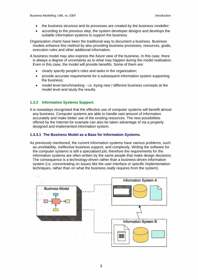
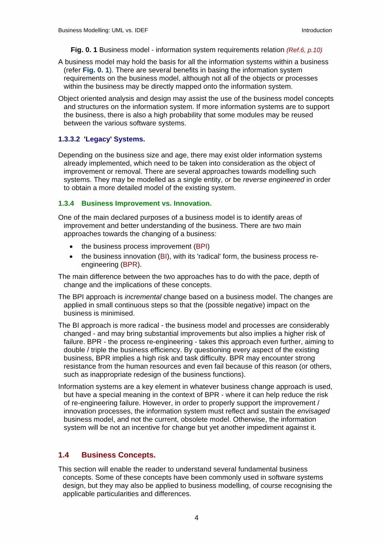
Fig. 0. 1 Business model - information system requirements relation (Ref.6, p.10)
A business model may hold the basis for all the information systems within a business (refer Fig. 0. 1). There are several benefits in basing the information system requirements on the business model, although not all of the objects or processes within the business may be directly mapped onto the information system.
Object oriented analysis and design may assist the use of the business model concepts and structures on the information system. If more information systems are to support the business, there is also a high probability that some modules may be reused between the various software systems.
1.3.3.2 'Legacy' Systems.
Depending on the business size and age, there may exist older information systems already implemented, which need to be taken into consideration as the object of improvement or removal. There are several approaches towards modelling such systems. They may be modelled as a single entity, or be reverse engineered in order to obtain a more detailed model of the existing system.
1.3.4 Business Improvement vs. Innovation.
One of the main declared purposes of a business model is to identify areas of improvement and better understanding of the business. There are two main approaches towards the changing of a business:
• the business process improvement (BPI) • the business innovation (BI), with its 'radical' form, the business process re-
engineering (BPR).
The main difference between the two approaches has to do with the pace, depth of change and the implications of these concepts.
The BPI approach is incremental change based on a business model. The changes are applied in small continuous steps so that the (possible negative) impact on the business is minimised.
The BI approach is more radical - the business model and processes are considerably changed - and may bring substantial improvements but also implies a higher risk of failure. BPR - the process re-engineering - takes this approach even further, aiming to double / triple the business efficiency. By questioning every aspect of the existing business, BPR implies a high risk and task difficulty. BPR may encounter strong resistance from the human resources and even fail because of this reason (or others, such as inappropriate redesign of the business functions).
Information systems are a key element in whatever business change approach is used, but have a special meaning in the context of BPR - where it can help reduce the risk of re-engineering failure. However, in order to properly support the improvement / innovation processes, the information system must reflect and sustain the envisaged business model, and not the current, obsolete model. Otherwise, the information system will be not an incentive for change but yet another impediment against it.
1.4 Business Concepts.
This section will enable the reader to understand several fundamental business concepts. Some of these concepts have been commonly used in software systems design, but they may also be applied to business modelling, of course recognising the applicable particularities and differences.
4
Business Modelling: UML vs. IDEF Introduction
1.4.1 Business Architecture.
A business architecture may be loosely defined as a set of elements and the well-defined relations between them that form a whole defined by its functionality (Adapted from Ref.2). A well-documented business architecture which includes the situations, structures and behaviour represents a valuable business strategic asset. It will enable and assist the identification of new business opportunities / areas of improvement and baseline the information systems that support the business.
A good architecture must represent the business as accurately as possible. There may be different levels of abstraction for architectures, depending on the purpose, the processes and the structure modelled. A good architecture must be adaptable and also be accepted as a common view by both the business stakeholders and the workers. Last but not least, a good architecture must be easy to understand by its users and promote communication among them.
The relation between business and software architectures is further described in Section V of this Chapter.
1.4.2 Business Rules.
Business rules ensure that the business is run in accordance with external or internal restrictions and/or goals. Very often, the rules are regarded as facts, although there is a difference between a fact (which when asserted, represents knowledge) and a rule (which may be used to infer new knowledge, e.g. in expert systems).
Rules may be defined at all necessary levels, from e.g. high strategic level down to detailed requirements on an information system. Rules represent a common area of business and software modelling because software design may use a large proportion of the information contained in business rules.
Business rules may be structured in categories according to various criteria. Current developments in business modelling (Ref.6) identify four main categories of rules:
1.4.2.1 Derivations.
Derivation rules define how knowledge or information in one form may be transformed into another form. Derivation rules may be computational (calculate a value) or inference rules (if-then form).
1.4.2.2 Constraints.
Constraint rules are an important mechanism in integrity preservation, in processes such as object creation and relationship modification. Constraint rules may be of the structural (static), operational (dynamic) and stimulus/response (event based) types.
1.4.2.3 Existence.
Existence rules act when a specific object exists. They may be used in pre- and post conditions for object creation / deletion, etc.
1.4.3 Business Views.
Businesses are complex systems. The concept of views may be employed in order to tackle this complexity. The development of the views (which show particular aspects of the business) should be accomplished not in isolation, one by one, but rather incrementally for the whole set of views. As more information about the business is
5

Business Modelling: UML vs. IDEF Introduction
collected, the views evolve. Recent developments in business modelling (Ref.6) propose a set of four business views, as follows:
1.4.3.1 Vision.
The vision depicts the goal structure for the company and the obstacles that have to be overcome in order to reach the goals. This view contains some vital concepts for the business, such as: the mission, objectives (specific, 'schedulable' goals), strengths, weaknesses, threats to the business (e.g. competitors), critical factors for success, strategies, core competencies, roles, key processes, etc. The business vision view also includes identifying future trends from customer / competitor market analysis.
The vision view may employ several analysis methods, such as strategy definition, conceptual modelling (model level) and goal / problem modelling (user model level).
1.4.3.2 Process.
The Process view relies on the goals defined in the Vision view in order to describe the processes needed to achieve a specific objective. This view has to model the core processes of the company (critical for the existence of the business). The processes act as models (classes), while a process execution is a process instance (object). Process modelling may be achieved using various approaches. This paper will only describe the UML extensions and the IDEF1-4 approaches, which imply concepts such as goal, input, output, supply, control.
1.4.3.3 Structure.
The structure view represents the resources, products/services, and the information in the business. This type of view is also used by reference architectures (Ref.11).
Information modelling has a special meaning - information is a special type of resource that may sometimes govern the business. Therefore it is modelled separately and it actually represents the base for the information system storage definition (refer IDEF1 vs. IDEF1x later on in this document).
Organization is a case of resource modelling where the resources are allocated to organisational units. A process may stretch over more organisational units. The organization model aims to show the resource allocation, reporting methods, task assignments and management. The trend is to move away from hierarchical, to flexible and dynamic (project-based) organization.
1.4.3.4 Behaviour.
The Process view describes the behaviour of the resource objects. The Behaviour view goes into further detail by analysing possible states, behaviours in each state and transitions between states. The state modelling is based on concepts such as states, events (causes of a state transition) and actions. The interaction modelling addresses the relations between processes and resources.
1.5 Software Architecture vs. Business Architecture.
This section aims to emphasize the connection and dependencies between the business architecture and the supporting software architecture. As previously stated, there are several incentives towards constructing a robust business architecture. One
6
Business Modelling: UML vs. IDEF Introduction
of the advantages listed was the capability to derive accurate software requirements from the business model.
Modern software modelling and architecture concepts as such have appeared before business modelling. Software modelling has already been used for some time in order to construct good software architecture. As a direct consequence, there is a pool of experienced software modellers and software modelling tools available.
One of the purposes of this paper is to investigate how the existing software modelling tools and skills may be used to model businesses, and also to assess the suitability of the current attempts towards business modelling. The main concept is:
Use software development tools and human skills to develop the business model. Subsequently, use this model to derive requirements and accurately construct the supporting information system architecture.
1.5.1 Software Architecture.
The definition of business architecture (Section IV, A) may be also applied to software architecture, the only difference being the nature of the system (software in this case).
Aspects of a software architecture are as follows:
• functional aspect: refers to the functions required and the system capability to perform these functions. The functional requirements should be derived from the business model;
• non-functional aspect: does not refer to a specific function, but it affects the whole system (e.g. security, performance);
• development aspect: more specific, refers to reusability, cost, modifiability, etc.
1.5.2 Software Architectural Views.
Software architectural views aim to represent a particular aspect of the system in order to reduce overall complexity. The software architectural views are: • use case: the view of the user. It is the ultimate goal of the software system and
therefore may drive the development of the other views; • logical: this view shows classes, packages, states, behaviour and collaboration; • deployment: described the system topology (physical nodes containing
processes and components) • implementation: defines the code modules, both source and executables; • process: defined processes and threads, startup / shutdown of the system, etc.
1.5.3 From Business To Software Architecture.
Translating the business model into a software model is not a straightforward process. Not all the classes and objects defined in a business architecture may be mapped directly to a software model (nor should they be mapped an a one-to-one basis).
The business model may be used in the software development process in order to: • make a decision regarding the information system best suited for the business
(new, standard, legacy); • define functional requirements: the set of use cases / functions the software
system should supply to the business; • define non-functional requirements (affecting the whole system);
7

Business Modelling: UML vs. IDEF Introduction
• identify suitable business components that encapsulate a specific area of business functionality.
Conclusion: Business modelling may significantly assist and improve the software modelling process. 'Porting' the business model components to the software domain is not straightforward.
8
Business Modelling: UML vs. IDEF The Unified Modelling Language
2 The Unified Modelling Language (UML).
This section aims to provide a very concise primer to UML, especially from a business point of view. For more detailed information about UML please refer to the information sources mentioned in the References section.
2.1 Basics.
UML may be regarded the successor of the Object Oriented Analysis and Design (OOAD) methods that proliferated during the method wars of the '80s and early '90s.UML represents only the language component of a method and it is complemented separately by a Rational Unified Process (or RUP, which is not mandatory).
UML represents the unification of the three main modelling language methods within the industry: Booch, Rumbaugh and Jacobson. UML went through a standardisation process with the Object Management Group (OMG) and it is now an OMG standard.
UML is a modelling language. As such, it contains a set of symbols (the notation) and a group of rules (semantics) that manage the language. Rules may be classified into:
• syntactic: specify the aspect and combination of rules; • semantic: specify the meaning of the symbols, individually and in context; • pragmatic: guidelines on how to use the language (the intent of the symbols).
The most important concepts in understanding UML are: the UML architecture, notation (diagrams), constraints and extension mechanisms. The UML architecture does not directly concern the scope of this paper; therefore, it will not be covered. The diagrams, constraints and extension mechanisms have direct connection to the business modelling attempt and as a consequence they will be briefly explained.
2.2 UML Diagrams.
The UML contains nine type of diagrams, of which seven are used in business modelling. The diagram examples provided are meant to express (as much as possible) business models or information systems supporting (and part of) businesses.
N.B.: while all of these diagrams have their own well-defined graphical representation, only
the most useful towards our purpose (i.e. business modelling) will be shown in this paper. A complete coverage of UML diagrams is beyond the scope of this work.
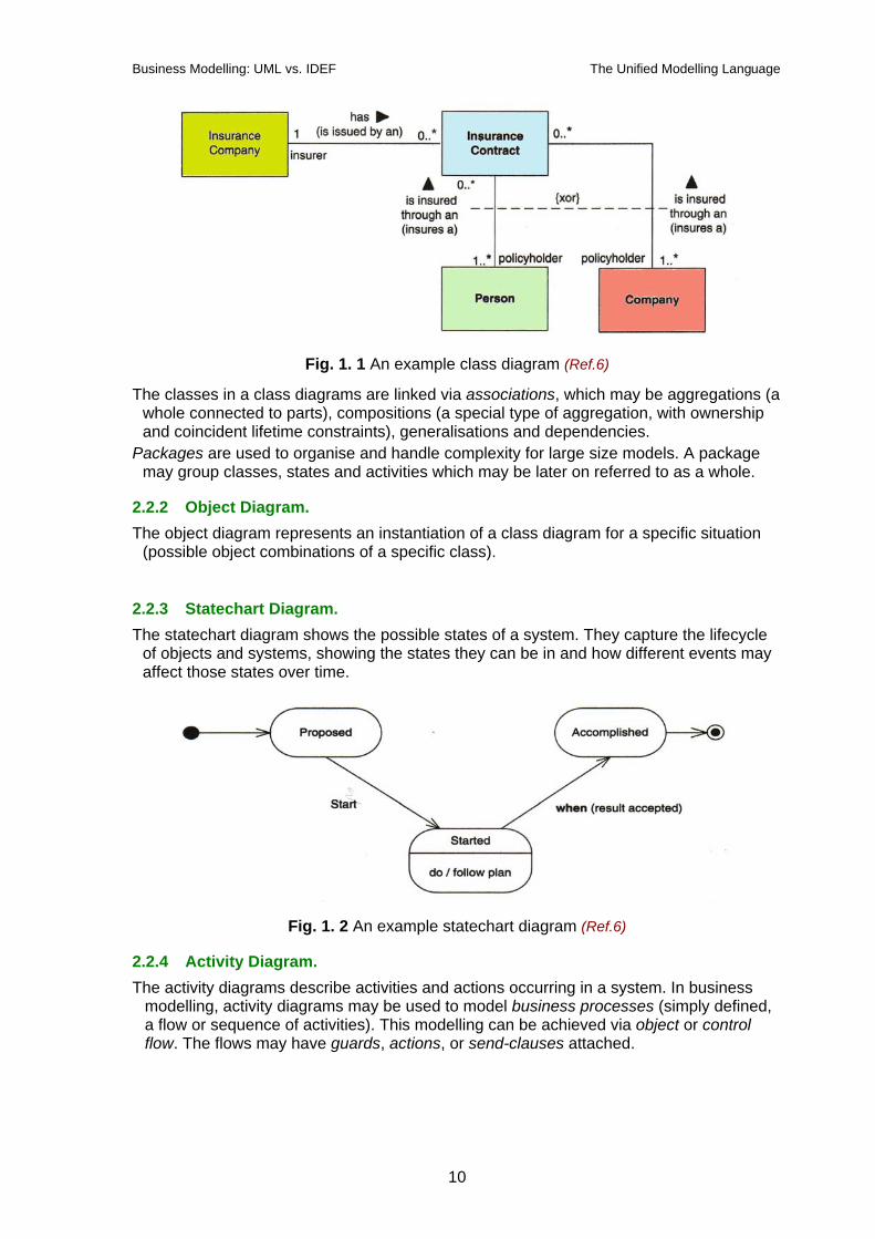
2.2.1 Class Diagram. A class diagram composed of classes and relationships. It describes the structure of a
system. The classes may represent information, products, documents, or organizations. A sample class diagram is shown in Fig. 1. 1.
9
Business Modelling: UML vs. IDEF The Unified Modelling Language
Fig. 1. 1 An example class diagram (Ref.6)
The classes in a class diagrams are linked via associations, which may be aggregations (a whole connected to parts), compositions (a special type of aggregation, with ownership and coincident lifetime constraints), generalisations and dependencies.
Packages are used to organise and handle complexity for large size models. A package may group classes, states and activities which may be later on referred to as a whole.
2.2.2 Object Diagram. The object diagram represents an instantiation of a class diagram for a specific situation
(possible object combinations of a specific class).
2.2.3 Statechart Diagram. The statechart diagram shows the possible states of a system. They capture the lifecycle
of objects and systems, showing the states they can be in and how different events may affect those states over time.
Fig. 1. 2 An example statechart diagram (Ref.6)
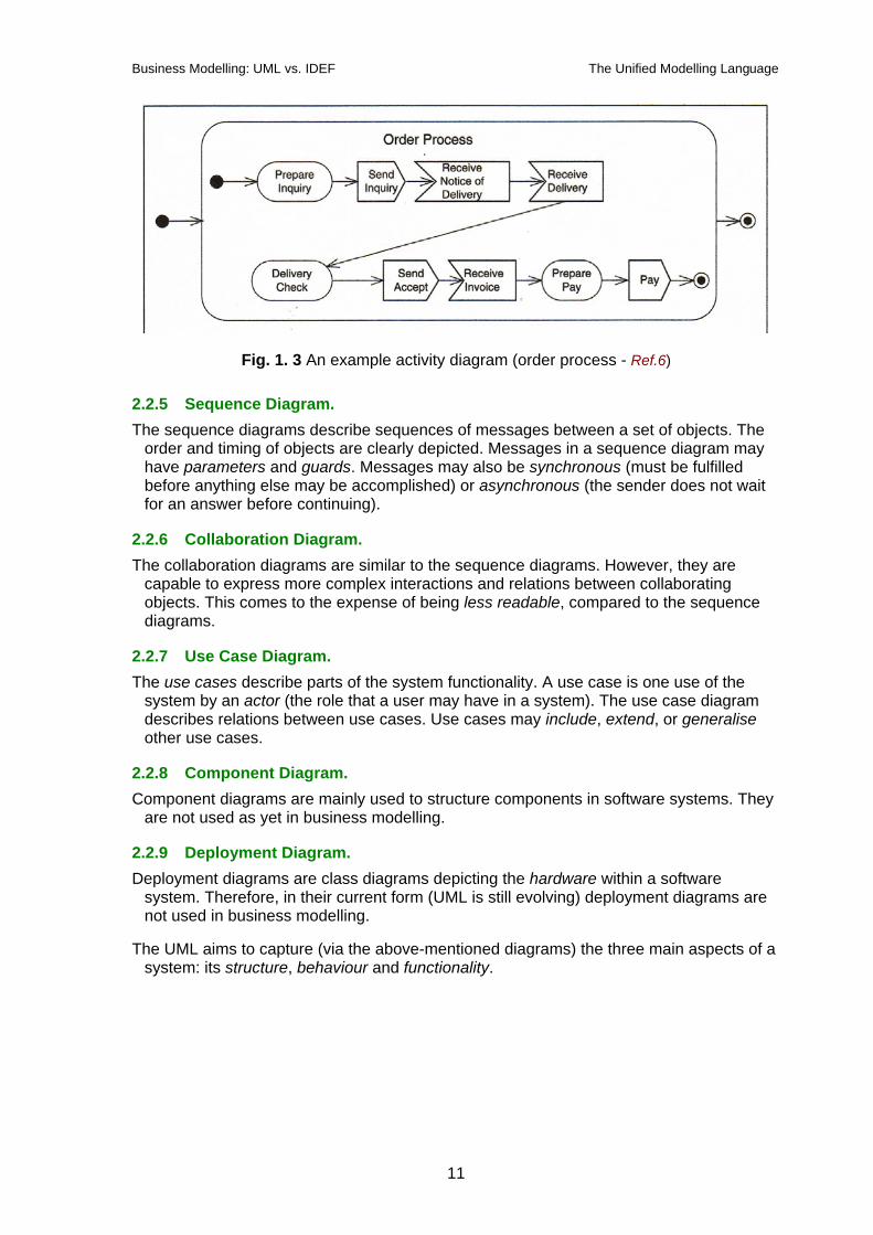
2.2.4 Activity Diagram. The activity diagrams describe activities and actions occurring in a system. In business
modelling, activity diagrams may be used to model business processes (simply defined, a flow or sequence of activities). This modelling can be achieved via object or control flow. The flows may have guards, actions, or send-clauses attached.
10
Business Modelling: UML vs. IDEF The Unified Modelling Language
Fig. 1. 3 An example activity diagram (order process - Ref.6)
2.2.5 Sequence Diagram. The sequence diagrams describe sequences of messages between a set of objects. The
order and timing of objects are clearly depicted. Messages in a sequence diagram may have parameters and guards. Messages may also be synchronous (must be fulfilled before anything else may be accomplished) or asynchronous (the sender does not wait for an answer before continuing).
2.2.6 Collaboration Diagram. The collaboration diagrams are similar to the sequence diagrams. However, they are
capable to express more complex interactions and relations between collaborating objects. This comes to the expense of being less readable, compared to the sequence diagrams.
2.2.7 Use Case Diagram. The use cases describe parts of the system functionality. A use case is one use of the
system by an actor (the role that a user may have in a system). The use case diagram describes relations between use cases. Use cases may include, extend, or generalise other use cases.
2.2.8 Component Diagram. Component diagrams are mainly used to structure components in software systems. They
are not used as yet in business modelling.
2.2.9 Deployment Diagram. Deployment diagrams are class diagrams depicting the hardware within a software
system. Therefore, in their current form (UML is still evolving) deployment diagrams are not used in business modelling.
The UML aims to capture (via the above-mentioned diagrams) the three main aspects of a system: its structure, behaviour and functionality.
11
Business Modelling: UML vs. IDEF The Unified Modelling Language
2.3 Extension Mechanisms.
Extension mechanisms are provided by the UML in order to allow users to customise and extend the language to suit their particular needs. The mechanisms provided are:
2.3.1 Stereotypes.
Stereotypes allow users to define new building blocks from the existing set. Basically, all UML elements can be customised and/or extended by defining and naming using the stereotypes. General form of stereotypes is either <<stereotype-name>> or special (user-defined) stereotype icons.
2.3.2 Tagged Values.
As the name suggests, tagged values are composed of a tag and a value. Tagged value need not be always visible - they can be contained e.g. in a database record associated to the object, which is not graphically represented in a diagram. General form is: {tag=value}. Example: {version=1.1}
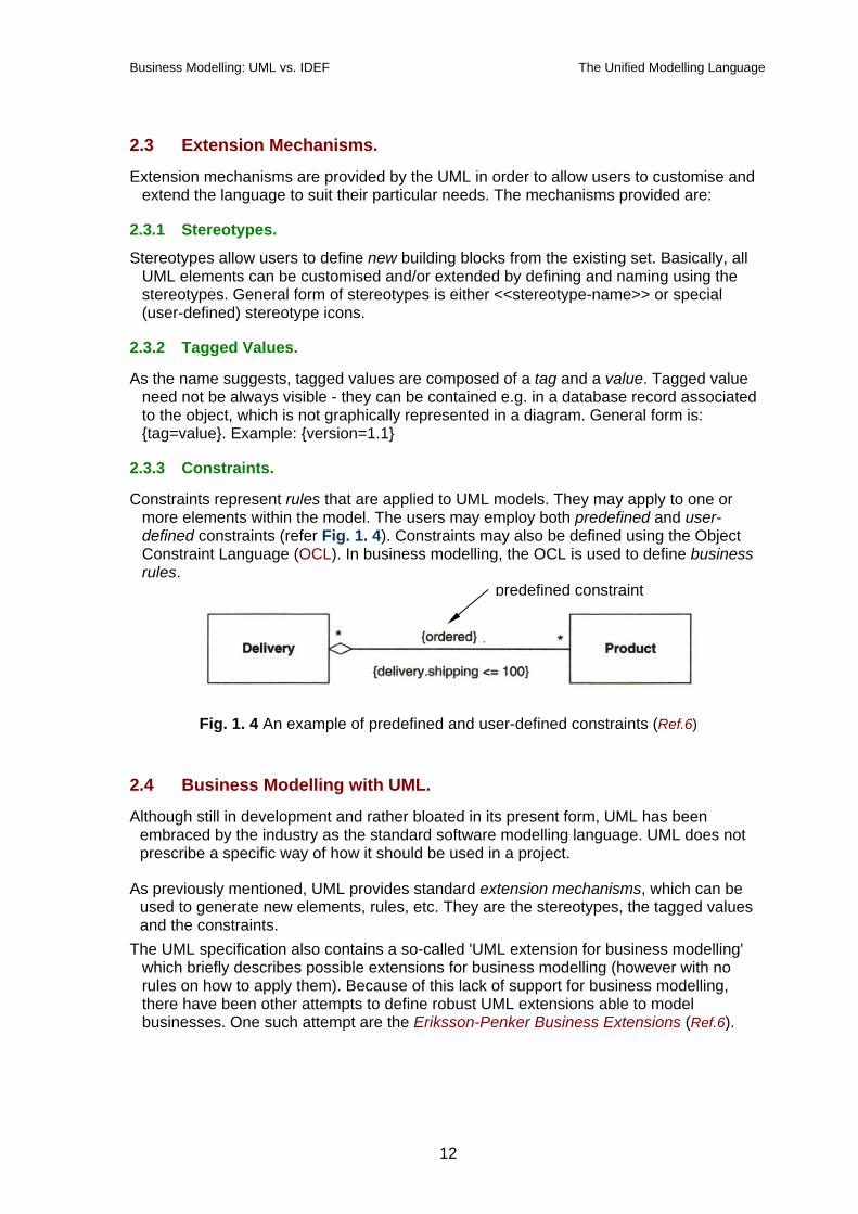
2.3.3 Constraints.
Constraints represent rules that are applied to UML models. They may apply to one or more elements within the model. The users may employ both predefined and user-defined constraints (refer Fig. 1. 4). Constraints may also be defined using the Object Constraint Language (OCL). In business modelling, the OCL is used to define business rules.
predefined constraint
Fig. 1. 4 An example of predefined and user-defined constraints (Ref.6)
2.4 Business Modelling with UML.
Although still in development and rather bloated in its present form, UML has been embraced by the industry as the standard software modelling language. UML does not prescribe a specific way of how it should be used in a project.
As previously mentioned, UML provides standard extension mechanisms, which can be used to generate new elements, rules, etc. They are the stereotypes, the tagged values and the constraints.
The UML specification also contains a so-called 'UML extension for business modelling' which briefly describes possible extensions for business modelling (however with no rules on how to apply them). Because of this lack of support for business modelling, there have been other attempts to define robust UML extensions able to model businesses. One such attempt are the Eriksson-Penker Business Extensions (Ref.6).
12

Business Modelling: UML vs. IDEF The Unified Modelling Language
2.4.1 Components of UML used in Business Modelling.
As mentioned, business modelling makes use of seven out of the nine UML diagrams. Business rules may be defined by using the Object Constraint Language, the OCL.
In order to successfully model a business there is an obvious need to model its dynamic components, i.e. the business processes. The Eriksson-Penker Business Extensions actually merge UML with process modelling, providing a much needed specialised UML extension able to handle business process modelling.
2.4.2 Business Rules.
The Object Constraint Language is used by the Eriksson-Penker Business Extensions to define business rules. Business rules have already been covered in Chapter 0, Section IV, part B.
2.4.3 The Eriksson-Penker Business Extensions.
The Eriksson-Penker Business Extensions are intended as a basic framework for business modelling. Using these extensions, the business architects may add stereotypes and/or properties to the UML in order to suit their particular situation.
The Eriksson-Penker extensions achieve process representation in UML by stereotyping an activity (from a UML activity diagram) to a <<process>>. In this approach, a process takes input resources from the left-hand side and outputs resources on the right-hand side.
Fig. 1. 5 Generic process diagram (Ref.6, p.69)
The generic representation in Fig. 1. 5 bears a great resemblance with an IDEF0 diagram, which proves that the essential set of concepts necessary and sufficient for business process modelling remains the same irrespective of the particular implementation.
The main objects used in the process model are as follows:
13
Business Modelling: UML vs. IDEF The Unified Modelling Language
• goal objects: connected via a dependency stereotyped to <<achieve>> to the process activity; the goal object is part of a goal/problem (object) diagram;
• input objects: objects that are consumed or refined in the process. Input objects are actually resources - e.g. <<people>>, <<information>>, etc.
• output objects: objects (which are also resources) produced or refined in the process;
• supplying objects: resources participating in the process which are not consumed or refined in the process; their dependency is stereotyped to <<supply>>;
• controlling objects: resources that control or run the process; their dependency is stereotyped to <<control>>.
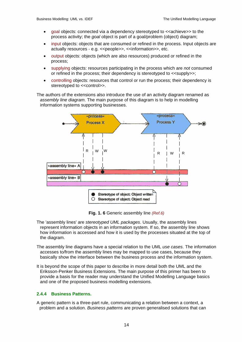
The authors of the extensions also introduce the use of an activity diagram renamed as assembly line diagram. The main purpose of this diagram is to help in modelling information systems supporting businesses.
W R W R R W
Fig. 1. 6 Generic assembly line (Ref.6)
The 'assembly lines' are stereotyped UML packages. Usually, the assembly lines represent information objects in an information system. If so, the assembly line shows how information is accessed and how it is used by the processes situated at the top of the diagram.
The assembly line diagrams have a special relation to the UML use cases. The information accesses to/from the assembly lines may be mapped to use cases, because they basically show the interface between the business process and the information system.
It is beyond the scope of this paper to describe in more detail both the UML and the Eriksson-Penker Business Extensions. The main purpose of this primer has been to provide a basis for the reader may understand the Unified Modelling Language basics and one of the proposed business modelling extensions.
2.4.4 Business Patterns.
A generic pattern is a three-part rule, communicating a relation between a context, a problem and a solution. Business patterns are proven generalised solutions that can
14

Business Modelling: UML vs. IDEF The Unified Modelling Language
solve problems common to different business situations. Patterns are a way of reusing previous modeller experience. They exist in all phases of development - from business modelling to the coding and testing phases. Patterns can be of functional, structural and behavioural categories, depending on the issues they deal with.
The pattern form refers to the intent of the pattern. A classification by the form of the pattern will yield three categories: • resource and rule patterns: structural (mainly static) • goal patterns: structural (mainly static); • process patterns: functional and behavioural (mainly dynamic).
Several patterns are being proposed for the purpose of business modelling. Some of these patterns will be used in the modelling exercise presented in Chapter 3.
15
Business Modelling: UML vs. IDEF The IDEF Family of Languages
3 The IDEF Family of Languages. Business process analysis and modelling methodologies have the potential of bridging
the gap between the information systems requirements definition and software systems development. Traditionally however, business analysts have had difficulties in capturing 'as-is' models of businesses in order to better understand and subsequently improve them. Fortunately, the advent of modelling tools supporting the application of business modelling methods has changed this situation.
This chapter will briefly present the IDEF group of languages, with emphasis on IDEF0,
IDEF1 / IDEF1x, IDEF3 and IDEF4. In order to present each language, a concise discussion of the underlying ontology must be undertaken, together with the notion of model in that particular language interpretation. Finally, the specific language semantic rules must be briefly described in order to enable the reader to gain an understanding of that particular language and its intended areas of application.
3.1 Basics.
The IDEF (ICAM DEFinition, becoming Integrated DEFinition) methodology was initially intended for use in systems engineering. In the 1970s, the system design and analysis domains were in need of supporting modelling methods. The US Air Force Integrated Computer Aided Manufacturing (ICAM) program addressed this need by devising the suite of methods known as IDEF.
The IDEF suite initially contained an activity (function) modelling method, called IDEF0, a conceptual modelling method called IDEF1 and a simulation model specification method - the IDEF2. Since then, other developments saw several constructs added to the IDEF1, which gave birth to IDEF1x. Also, work on a process modelling method known as IDEF3 was started in the 1980s. IDEF3 has actually taken over much of the scope of IDEF2 because it can be used to specify preliminary simulation models. Furthermore, IDEF3 has an object-state component that can be used to model how objects undergo change in a process.
IDEF4 and IDEF5 followed in the 1990s. IDEF4 is an object-oriented software design method that integrates the requirements specified in other methods. IDEF4 also allows capturing and management of (object-oriented) design principles. IDEF5 is a knowledge acquisition and engineering method aiming to support enterprise ontologies - i.e. the theories supporting metamodels.
The complete list of IDEF methods goes from IDEF0 to IDEF14 (from IDEF5 upwards mostly in development and IDEF7 missing from the list).
Presently, the methods that are used most are IDEF0, IDEF1x, IDEF3 and IDEF4. Recent developments aim to effectively refine and integrate these methods, so that information may be easily exchanged between them.
3.2 IDEF0.
The IDEF0 method is used to specify function models ('what to do'). It is loosely based upon the Structured Analysis and Design Technique (SADT) method developed by Douglas Ross from SofTech in the 1970s.
IDEF0 allows the user to depict a view of the process including the inputs, outputs, controls and mechanisms (which are referred to generally as ICOMs):
16
Business Modelling: UML vs. IDEF The IDEF Family of Languages
• inputs are resources consumed or transformed (refined) by the process; • outputs are the things created through the consumption / transformation of the
inputs by the process; • controls are the things guiding the process: policies, guidelines, standards, laws; • mechanisms are the agents that accomplish the actions (activities) contained by
the process. Examples: people or manual and automated tools;
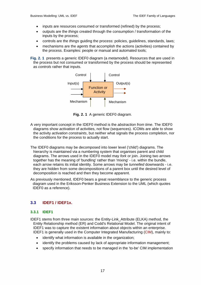
Fig. 2. 1 presents a generic IDEF0 diagram (a metamodel). Resources that are used in the process but not consumed or transformed by the process should be represented as controls rather that inputs.
Function or Activity
Mechanism Mechanism
Control Control
Input(s) Output(s)
Fig. 2. 1 A generic IDEF0 diagram.
A very important concept in the IDEF0 method is the abstraction from time. The IDEF0 diagrams show activation of activities, not flow (sequences). ICOMs are able to show the activity activation constraints, but neither what signals the process completion, nor the conditions for the process to actually start.
The IDEF0 diagrams may be decomposed into lower level ('child') diagrams. The
hierarchy is maintained via a numbering system that organises parent and child diagrams. The arrows used in the IDEF0 model may fork or join. Joining two arrows together has the meaning of 'bundling' rather than 'mixing' - i.e. within the bundle, each arrow retains its initial identity. Some arrows may be tunnelled downwards - i.e. they are hidden from some decompositions of a parent box until the desired level of decomposition is reached and then they become apparent.
As previously mentioned, IDEF0 bears a great resemblance to the generic process diagram used in the Eriksson-Penker Business Extension to the UML (which quotes IDEF0 as a reference).
3.3 IDEF1 / IDEF1x.
3.3.1 IDEF1
IDEF1 stems from three main sources: the Entity-Link_Attribute (ELKA) method, the Entity Relationship method (ER) and Codd's Relational Model. The original intent of IDEF1 was to capture the existent information about objects within an enterprise. IDEF1 is generally used in the Computer Integrated Manufacturing (CIM), mainly to: • identify what information is available in the organization; • identify the problems caused by lack of appropriate information management; • specify information that needs to be managed in the 'to-be' CIM implementation
17
Business Modelling: UML vs. IDEF The IDEF Family of Languages
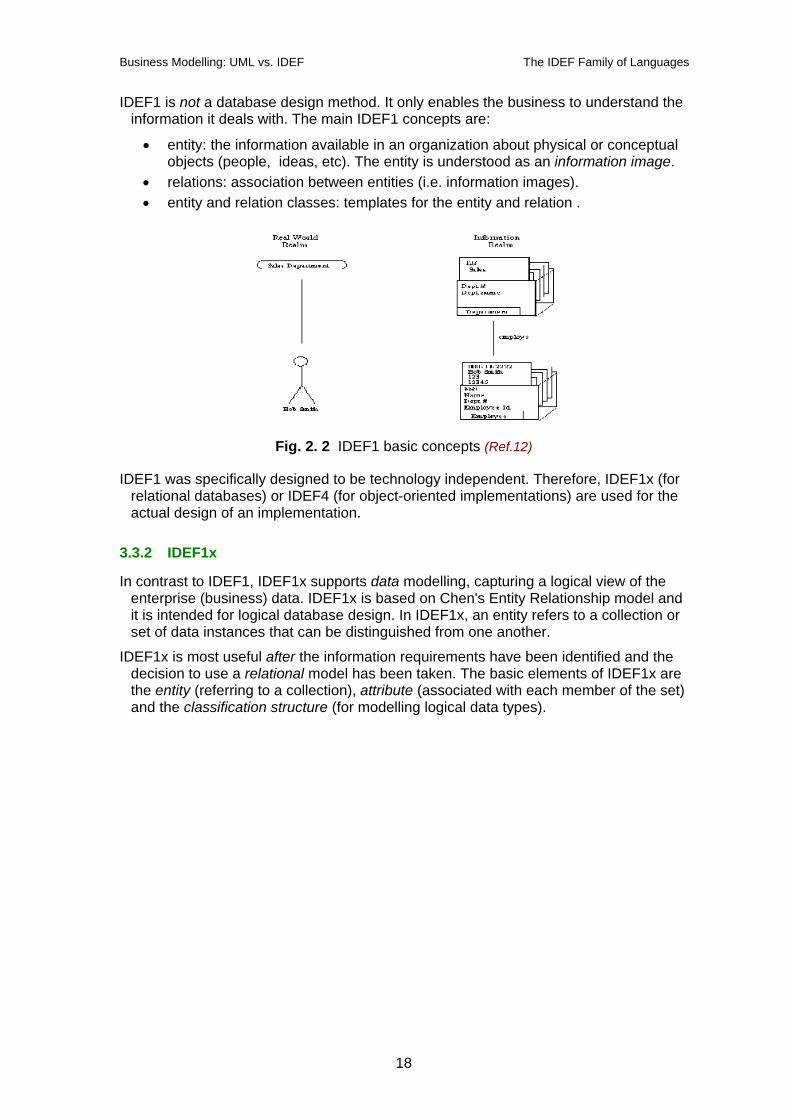
IDEF1 is not a database design method. It only enables the business to understand the information it deals with. The main IDEF1 concepts are:
• entity: the information available in an organization about physical or conceptual objects (people, ideas, etc). The entity is understood as an information image.
• relations: association between entities (i.e. information images). • entity and relation classes: templates for the entity and relation .
Fig. 2. 2 IDEF1 basic concepts (Ref.12)
IDEF1 was specifically designed to be technology independent. Therefore, IDEF1x (for relational databases) or IDEF4 (for object-oriented implementations) are used for the actual design of an implementation.
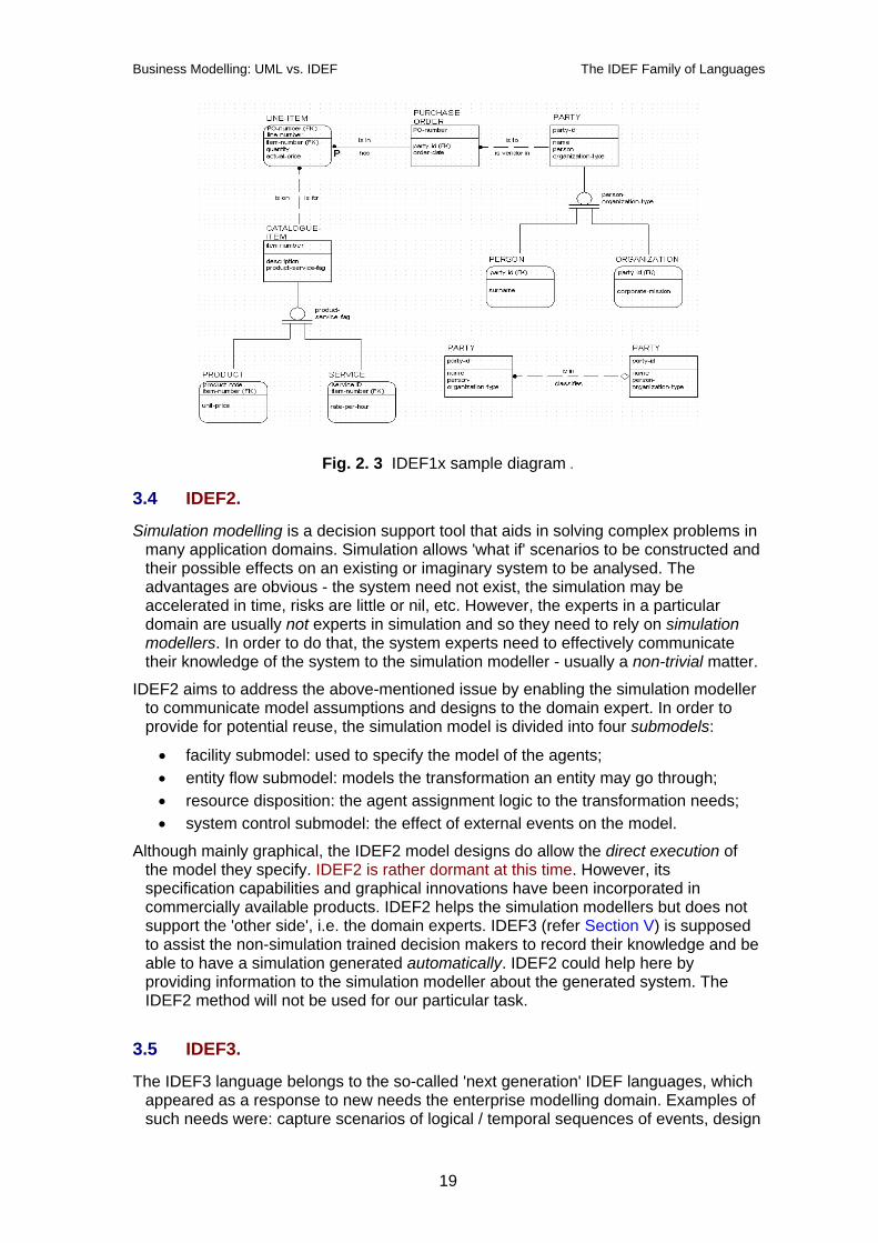
3.3.2 IDEF1x
In contrast to IDEF1, IDEF1x supports data modelling, capturing a logical view of the enterprise (business) data. IDEF1x is based on Chen's Entity Relationship model and it is intended for logical database design. In IDEF1x, an entity refers to a collection or set of data instances that can be distinguished from one another.
IDEF1x is most useful after the information requirements have been identified and the decision to use a relational model has been taken. The basic elements of IDEF1x are the entity (referring to a collection), attribute (associated with each member of the set) and the classification structure (for modelling logical data types).
18
Business Modelling: UML vs. IDEF The IDEF Family of Languages
Fig. 2. 3 IDEF1x sample diagram .
3.4 IDEF2.
Simulation modelling is a decision support tool that aids in solving complex problems in many application domains. Simulation allows 'what if' scenarios to be constructed and their possible effects on an existing or imaginary system to be analysed. The advantages are obvious - the system need not exist, the simulation may be accelerated in time, risks are little or nil, etc. However, the experts in a particular domain are usually not experts in simulation and so they need to rely on simulation modellers. In order to do that, the system experts need to effectively communicate their knowledge of the system to the simulation modeller - usually a non-trivial matter.
IDEF2 aims to address the above-mentioned issue by enabling the simulation modeller to communicate model assumptions and designs to the domain expert. In order to provide for potential reuse, the simulation model is divided into four submodels:
• facility submodel: used to specify the model of the agents; • entity flow submodel: models the transformation an entity may go through; • resource disposition: the agent assignment logic to the transformation needs; • system control submodel: the effect of external events on the model.
Although mainly graphical, the IDEF2 model designs do allow the direct execution of the model they specify. IDEF2 is rather dormant at this time. However, its specification capabilities and graphical innovations have been incorporated in commercially available products. IDEF2 helps the simulation modellers but does not support the 'other side', i.e. the domain experts. IDEF3 (refer Section V) is supposed to assist the non-simulation trained decision makers to record their knowledge and be able to have a simulation generated automatically. IDEF2 could help here by providing information to the simulation modeller about the generated system. The IDEF2 method will not be used for our particular task.
3.5 IDEF3.
The IDEF3 language belongs to the so-called 'next generation' IDEF languages, which appeared as a response to new needs the enterprise modelling domain. Examples of such needs were: capture scenarios of logical / temporal sequences of events, design
19
Business Modelling: UML vs. IDEF The IDEF Family of Languages
object-oriented applications and databases, capture reference descriptions of the real-world objects and record decision rationale.
IDEF3 introduces the Process Description Capture Method, used by system developers to capture domain expert knowledge about the dynamic (behavioural) aspects of a system. IDEF3 constructs models of enterprise processes and it is therefore similar to IDEF0. The major difference however is that while IDEF0 adopts a single view of the system, IDEF3 accommodates several user descriptions of the temporal precedence of processes (user views). The result of the IDEF3 method is rather a description than a model. IDEF3 contains two modelling approaches:
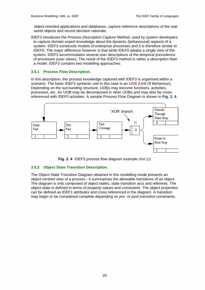
3.5.1 Process Flow Description.
In this description, the process knowledge captured with IDEF3 is organised within a scenario. The basic IDEF3 syntactic unit in this case is an UOB (Unit Of Behaviour), Depending on the surrounding structure, UOBs may become functions, activities, processes, etc. An UOB may be decomposed in other UOBs and may also be cross-referenced with IDEF0 activities. A sample Process Flow Diagram is shown in Fig. 2. 4.
'XOR' branch
Fig. 2. 4 IDEF3 process flow diagram example (Ref.12)
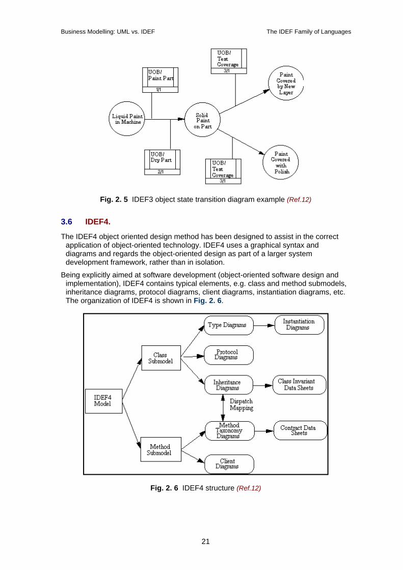
3.5.2 Object State Transition Description.
The Object State Transition Diagram obtained in this modelling mode presents an object-centred view of a process - it summarizes the allowable transitions of an object. The diagram is only composed of object states, state transition arcs and referents. The object state is defined in terms of property values and constraints. The object properties can be defined as IDEF1 attributes and cross referenced in the diagram. A transition may begin or be considered complete depending on pre- or post-transition constraints.
20
Business Modelling: UML vs. IDEF The IDEF Family of Languages
Fig. 2. 5 IDEF3 object state transition diagram example (Ref.12)
3.6 IDEF4.
The IDEF4 object oriented design method has been designed to assist in the correct application of object-oriented technology. IDEF4 uses a graphical syntax and diagrams and regards the object-oriented design as part of a larger system development framework, rather than in isolation.
Being explicitly aimed at software development (object-oriented software design and implementation), IDEF4 contains typical elements, e.g. class and method submodels, inheritance diagrams, protocol diagrams, client diagrams, instantiation diagrams, etc. The organization of IDEF4 is shown in Fig. 2. 6.
Fig. 2. 6 IDEF4 structure (Ref.12)
21
Business Modelling: UML vs. IDEF The IDEF Family of Languages
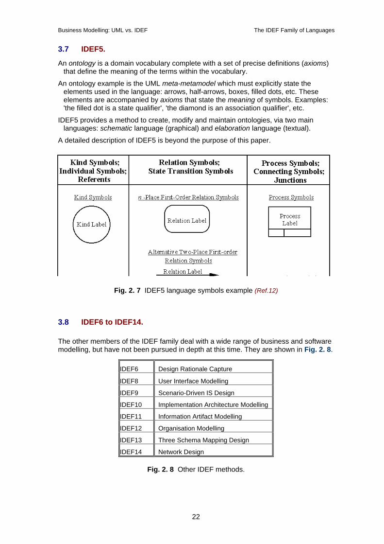
3.7 IDEF5.
An ontology is a domain vocabulary complete with a set of precise definitions (axioms) that define the meaning of the terms within the vocabulary.
An ontology example is the UML meta-metamodel which must explicitly state the elements used in the language: arrows, half-arrows, boxes, filled dots, etc. These elements are accompanied by axioms that state the meaning of symbols. Examples: 'the filled dot is a state qualifier', 'the diamond is an association qualifier', etc.
IDEF5 provides a method to create, modify and maintain ontologies, via two main languages: schematic language (graphical) and elaboration language (textual).
A detailed description of IDEF5 is beyond the purpose of this paper.
Fig. 2. 7 IDEF5 language symbols example (Ref.12)
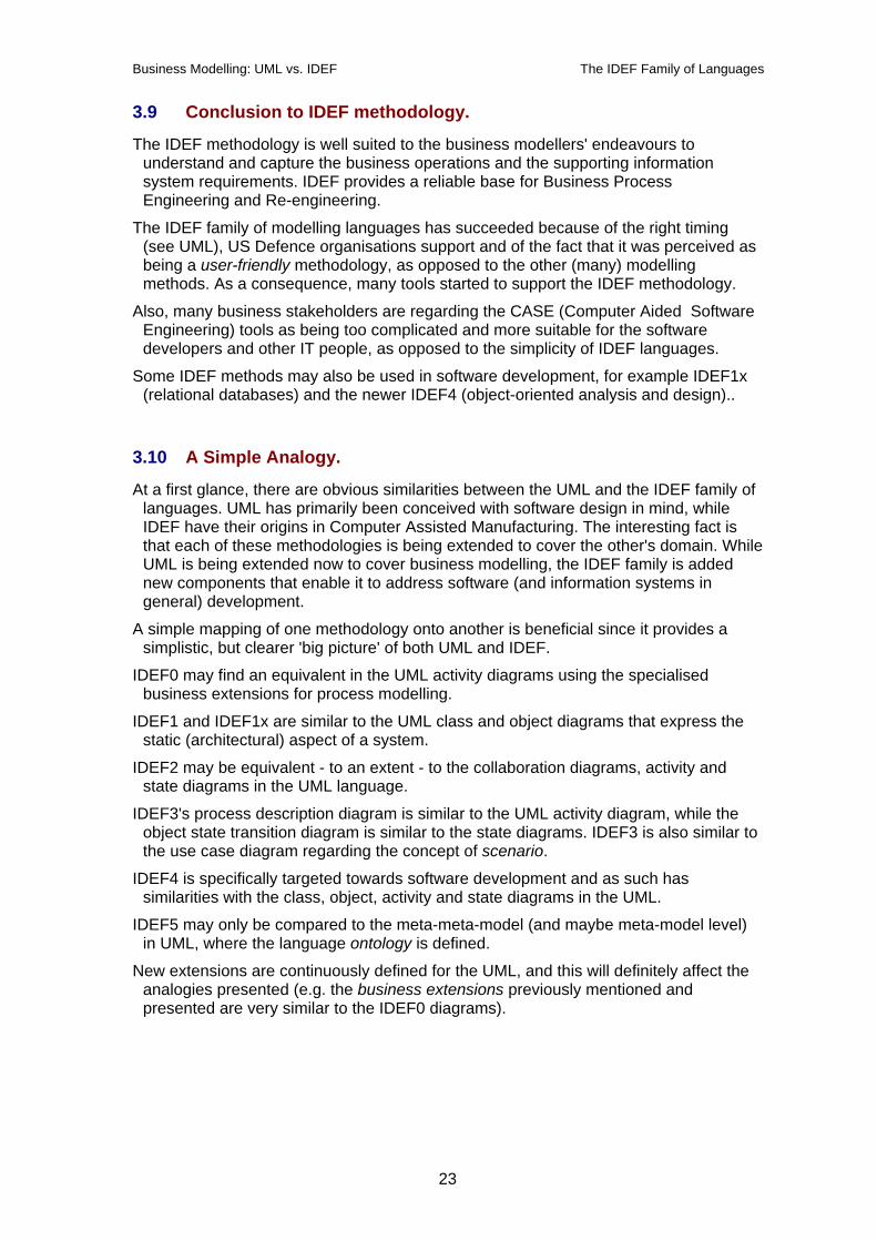
3.8 IDEF6 to IDEF14. The other members of the IDEF family deal with a wide range of business and software modelling, but have not been pursued in depth at this time. They are shown in Fig. 2. 8.
IDEF6 Design Rationale Capture
IDEF8 User Interface Modelling
IDEF9 Scenario-Driven IS Design
IDEF10 Implementation Architecture Modelling
IDEF11 Information Artifact Modelling
IDEF12 Organisation Modelling
IDEF13 Three Schema Mapping Design
IDEF14 Network Design
Fig. 2. 8 Other IDEF methods.
22
Business Modelling: UML vs. IDEF The IDEF Family of Languages
3.9 Conclusion to IDEF methodology.
The IDEF methodology is well suited to the business modellers' endeavours to understand and capture the business operations and the supporting information system requirements. IDEF provides a reliable base for Business Process Engineering and Re-engineering.
The IDEF family of modelling languages has succeeded because of the right timing (see UML), US Defence organisations support and of the fact that it was perceived as being a user-friendly methodology, as opposed to the other (many) modelling methods. As a consequence, many tools started to support the IDEF methodology.
Also, many business stakeholders are regarding the CASE (Computer Aided Software Engineering) tools as being too complicated and more suitable for the software developers and other IT people, as opposed to the simplicity of IDEF languages.
Some IDEF methods may also be used in software development, for example IDEF1x (relational databases) and the newer IDEF4 (object-oriented analysis and design)..
3.10 A Simple Analogy.
At a first glance, there are obvious similarities between the UML and the IDEF family of languages. UML has primarily been conceived with software design in mind, while IDEF have their origins in Computer Assisted Manufacturing. The interesting fact is that each of these methodologies is being extended to cover the other's domain. While UML is being extended now to cover business modelling, the IDEF family is added new components that enable it to address software (and information systems in general) development.
A simple mapping of one methodology onto another is beneficial since it provides a simplistic, but clearer 'big picture' of both UML and IDEF.
IDEF0 may find an equivalent in the UML activity diagrams using the specialised business extensions for process modelling.
IDEF1 and IDEF1x are similar to the UML class and object diagrams that express the static (architectural) aspect of a system.
IDEF2 may be equivalent - to an extent - to the collaboration diagrams, activity and state diagrams in the UML language.
IDEF3's process description diagram is similar to the UML activity diagram, while the object state transition diagram is similar to the state diagrams. IDEF3 is also similar to the use case diagram regarding the concept of scenario.
IDEF4 is specifically targeted towards software development and as such has similarities with the class, object, activity and state diagrams in the UML.
IDEF5 may only be compared to the meta-meta-model (and maybe meta-model level) in UML, where the language ontology is defined.
New extensions are continuously defined for the UML, and this will definitely affect the analogies presented (e.g. the business extensions previously mentioned and presented are very similar to the IDEF0 diagrams).
23
Business Modelling: UML vs. IDEF A Simple Business Example
4 A Simple Business Example.
This Chapter will attempt to model part of a business process using both UML and IDEF. The problems and shortcomings encountered in the modelling will be documented. The tools used in the modelling will be:
• some UML diagrams and the Eriksson-Penker business modelling extensions; • only IDEF family members beneficial to this modelling exercise.
The UML modelling part will also make heavy use of the design patterns presented in Ref 6 applicable to this particular case.
4.1 Description.
'VITE' is a virtual enterprise, aimed at selling (for example) fruit and vegetables. The exact object of the virtual enterprise is not very important, as the vast majority of elements are there for any virtual enterprise.
The Virtual Enterprise (VE) in discussion has been largely described in Ref.12 . For the purpose of this exercise, we are only interested in the wholesaler VE component.
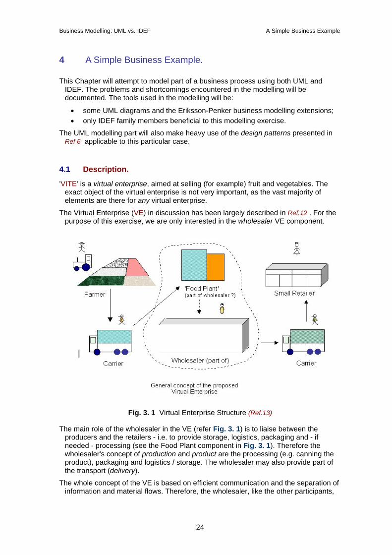
Fig. 3. 1 Virtual Enterprise Structure (Ref.13)
The main role of the wholesaler in the VE (refer Fig. 3. 1) is to liaise between the producers and the retailers - i.e. to provide storage, logistics, packaging and - if needed - processing (see the Food Plant component in Fig. 3. 1). Therefore the wholesaler's concept of production and product are the processing (e.g. canning the product), packaging and logistics / storage. The wholesaler may also provide part of the transport (delivery).
The whole concept of the VE is based on efficient communication and the separation of information and material flows. Therefore, the wholesaler, like the other participants,
24
Business Modelling: UML vs. IDEF A Simple Business Example
has to upgrade his interfaces in order to offer integration with the producer's and the retailer's purchase / selling processes.
Whatever the business modelling method, the vision and goals of the business should be the same: become the leading wholesaler in a specific business domain - a major goal being to increase its market share.
4.2 The UML model.
In the following we will extensively use applicable patterns, since they provide proven solutions to similar problems. The modelling process will follow the Eriksson-Penker method, with appropriate variations.
4.2.1 The Goals.
The main goal of the wholesaler is to increase its market share. In order to realise it, the wholesaler has to deal with several problems such as minimising threats from competition and increasing production and purchasing efficiency.
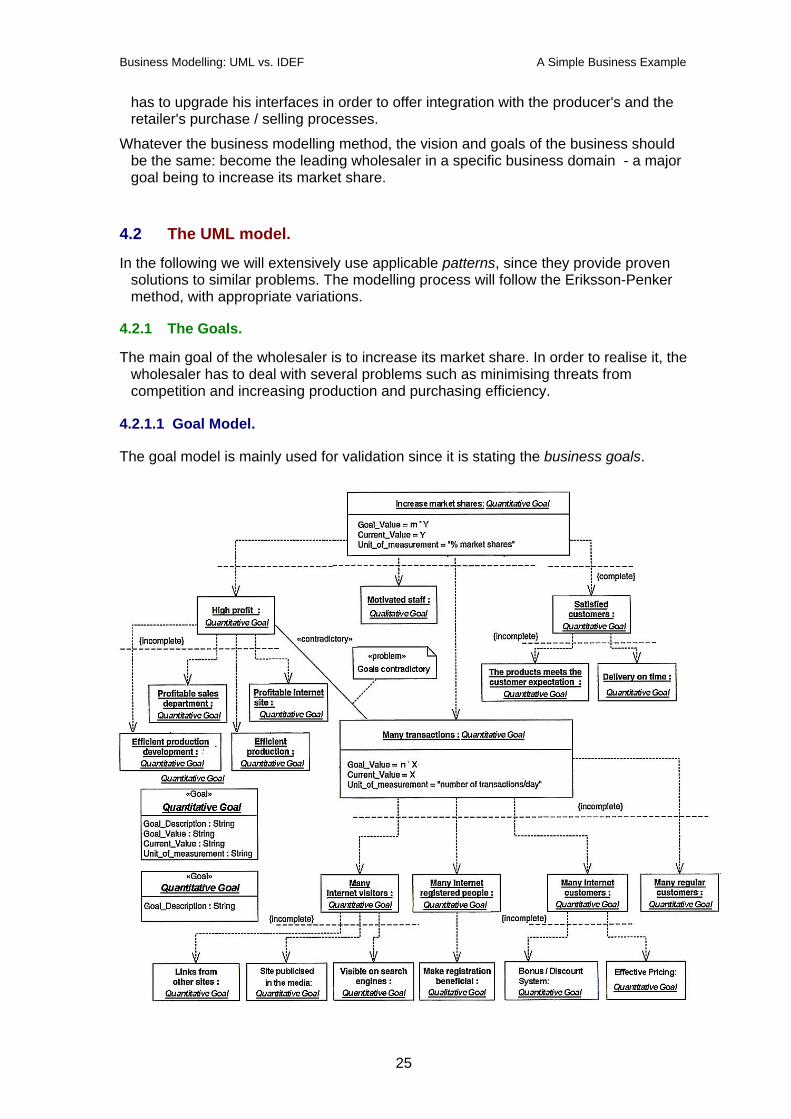
4.2.1.1 Goal Model.
The goal model is mainly used for validation since it is stating the business goals.
25
Business Modelling: UML vs. IDEF A Simple Business Example
Fig. 3. 2 Conceptual model (Adapted from Ref 6)
This model was obtained by applying the goal / problem and goal decomposition patterns.
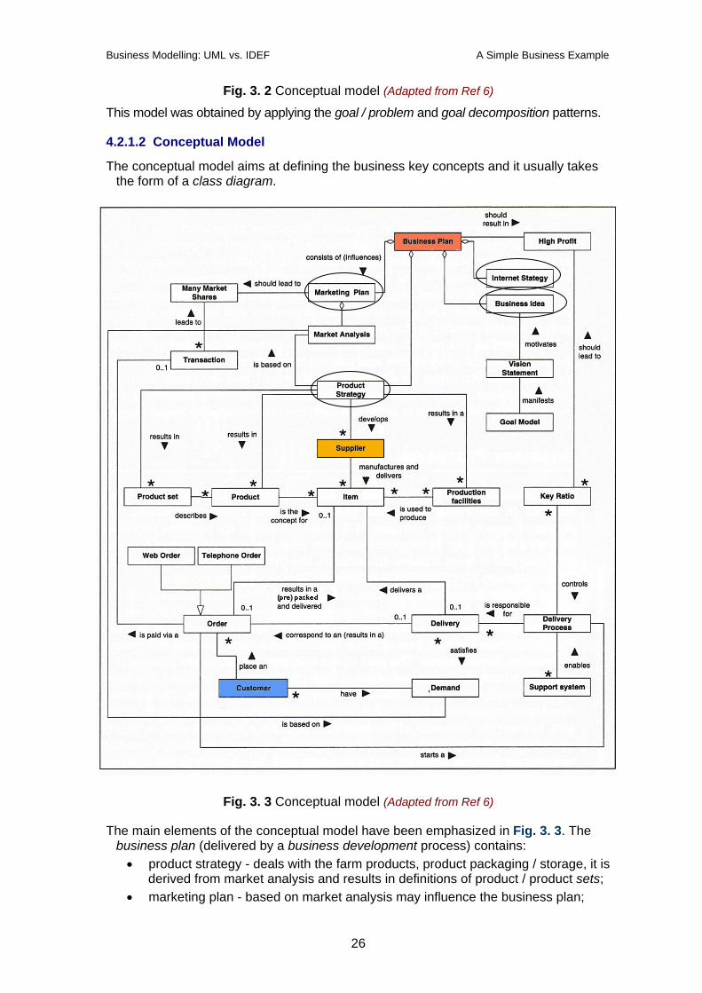
4.2.1.2 Conceptual Model
The conceptual model aims at defining the business key concepts and it usually takes the form of a class diagram.
Fig. 3. 3 Conceptual model (Adapted from Ref 6)
The main elements of the conceptual model have been emphasized in Fig. 3. 3. The business plan (delivered by a business development process) contains: • product strategy - deals with the farm products, product packaging / storage, it is
derived from market analysis and results in definitions of product / product sets; • marketing plan - based on market analysis may influence the business plan;
26
Business Modelling: UML vs. IDEF A Simple Business Example
• business ideas are an important business asset • Internet strategy - is a main component of the (VE) integration process.
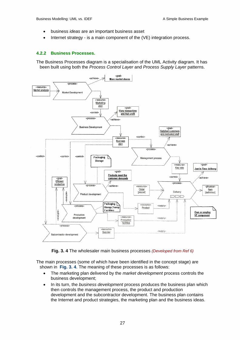
4.2.2 Business Processes.
The Business Processes diagram is a specialisation of the UML Activity diagram. It has been built using both the Process Control Layer and Process Supply Layer patterns.
Fig. 3. 4 The wholesaler main business processes (Developed from Ref 6) The main processes (some of which have been identified in the concept stage) are
shown in Fig. 3. 4. The meaning of these processes is as follows: • The marketing plan delivered by the market development process controls the
business development; • In its turn, the business development process produces the business plan which
then controls the management process, the product and production development and the subcontractor development. The business plan contains the Internet and product strategies, the marketing plan and the business ideas.
27
Business Modelling: UML vs. IDEF A Simple Business Example
• The management process aims to achieve satisfied customers and motivated staff. Its output is the key ratio controlling the delivery process.
• The product development process refers to the wholesaler's own production - which is packaging, processing and/or storing the product from the farmer (producer). Adequate quality must be ensured for these activities;
• The production development process must ensure the production facilities (in this case 'food plant' processing, packaging / storing and/or logistics facilities)
• The subcontractor development process must ensure the timely delivery of the product(s) by the suppliers (farmers and others) , so that the product(s) may be processed / packaged / stored / just-in-time delivered to the client;
• The delivery process has been represented assuming that the wholesaler has at least a partial involvement in the product delivery (often this is the real case).
Some conclusions from this model: accurate predictions of customer orders may help optimise the inventory size (e.g. long term vs. short term storage, necessary pre-processing, logistics, etc). Prompt processing of the customer orders must be ensured via the key ratio (which specify optimal periods of time to accomplish an order), supplying products that meet the customer expectations.
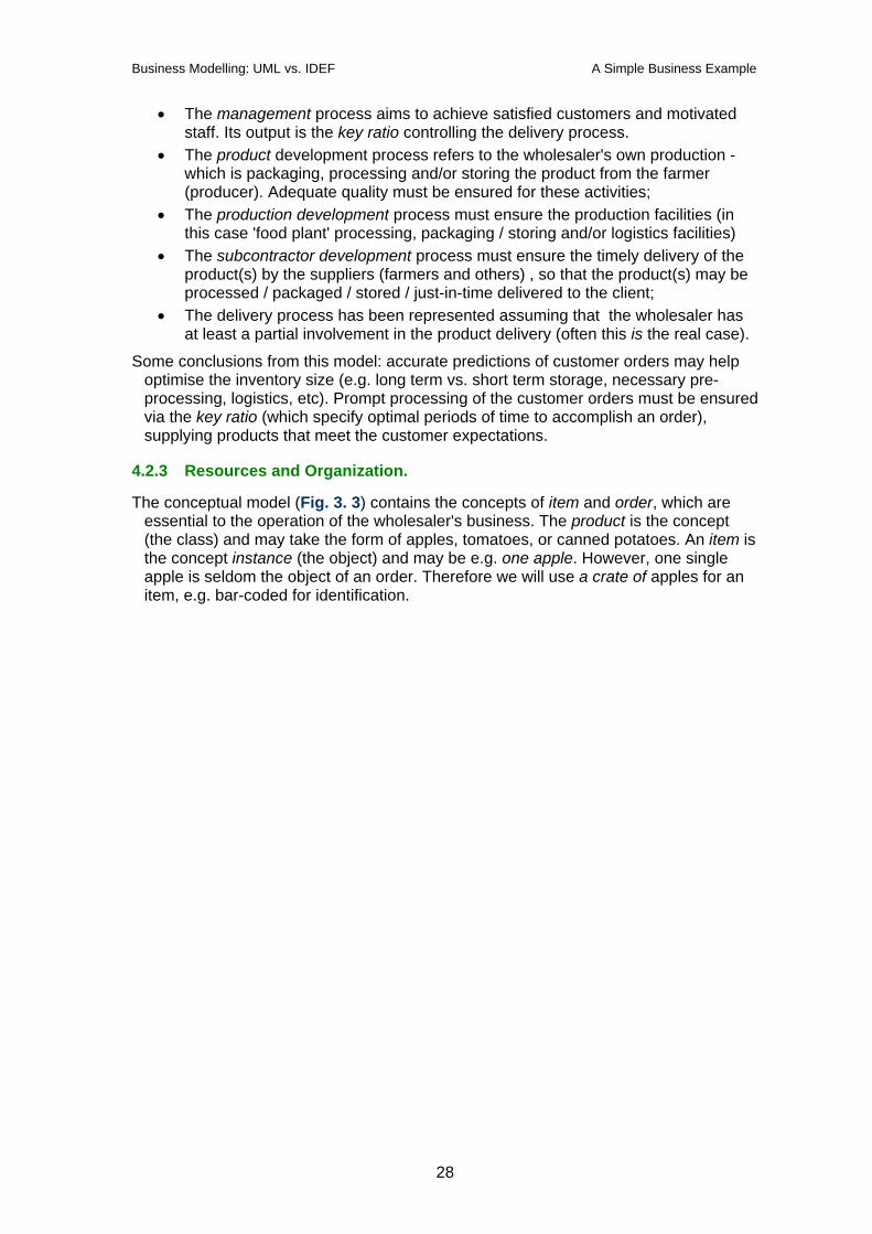
4.2.3 Resources and Organization.
The conceptual model (Fig. 3. 3) contains the concepts of item and order, which are essential to the operation of the wholesaler's business. The product is the concept (the class) and may take the form of apples, tomatoes, or canned potatoes. An item is the concept instance (the object) and may be e.g. one apple. However, one single apple is seldom the object of an order. Therefore we will use a crate of apples for an item, e.g. bar-coded for identification.
28
Business Modelling: UML vs. IDEF A Simple Business Example
Fig. 3. 5 The wholesaler resources model. The Product Data Management (PDM) and the Geographic Location patterns (Ref 6)
have been used to construct the resource model of the business. According to the PDM pattern, the Product Set is a powertype for Product. An instance of the Product Set may be 'canned fruit', and an instance of Product may be 'canned fruit pack no. [barcode]' (or even a particular can of fruit depending on the necessary granularity).
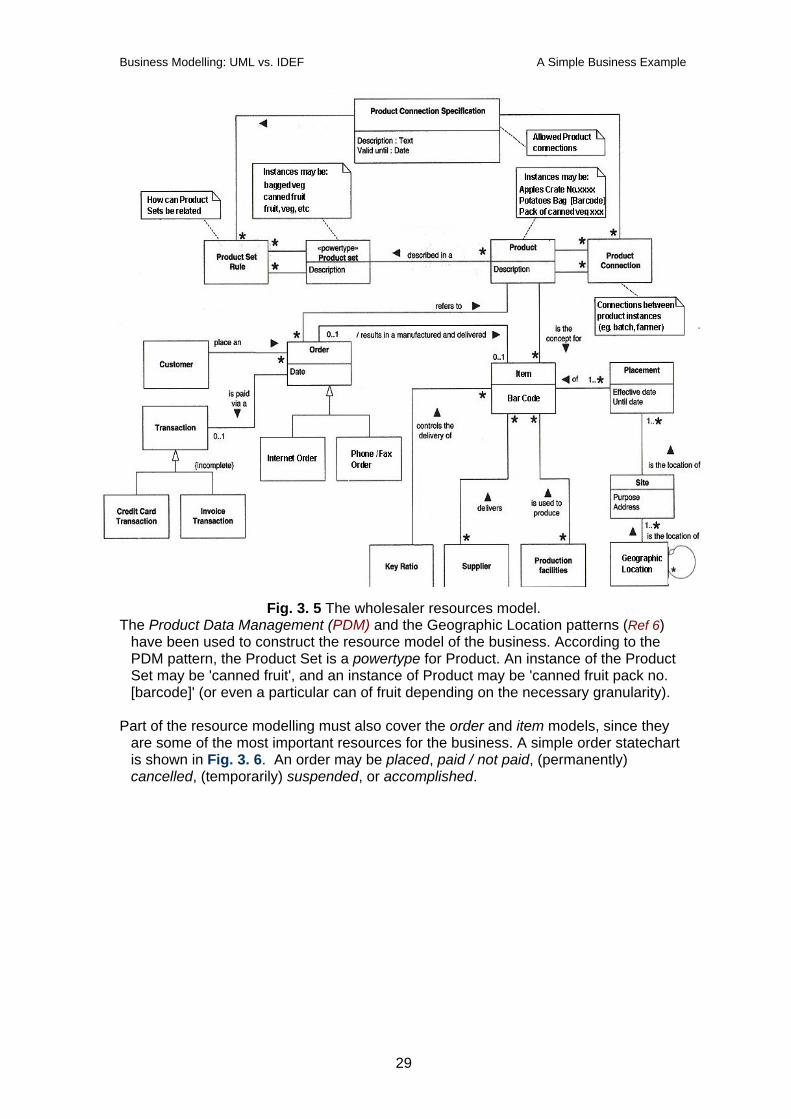
Part of the resource modelling must also cover the order and item models, since they
are some of the most important resources for the business. A simple order statechart is shown in Fig. 3. 6. An order may be placed, paid / not paid, (permanently) cancelled, (temporarily) suspended, or accomplished.
29
Business Modelling: UML vs. IDEF A Simple Business Example
Fig. 3. 6 Order Statechart Diagram. (Adapted from Ref 6)
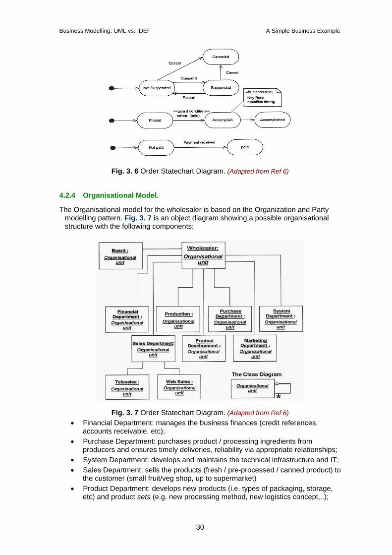
4.2.4 Organisational Model.
The Organisational model for the wholesaler is based on the Organization and Party modelling pattern. Fig. 3. 7 is an object diagram showing a possible organisational structure with the following components:
Fig. 3. 7 Order Statechart Diagram. (Adapted from Ref 6) • Financial Department: manages the business finances (credit references,
accounts receivable, etc); • Purchase Department: purchases product / processing ingredients from
producers and ensures timely deliveries, reliability via appropriate relationships; • System Department: develops and maintains the technical infrastructure and IT; • Sales Department: sells the products (fresh / pre-processed / canned product) to
the customer (small fruit/veg shop, up to supermarket) • Product Department: develops new products (i.e. types of packaging, storage,
etc) and product sets (e.g. new processing method, new logistics concept,..);
30
Business Modelling: UML vs. IDEF A Simple Business Example
• Marketing Department: implements the marketing plan and provides marketing services (forecasts, etc).
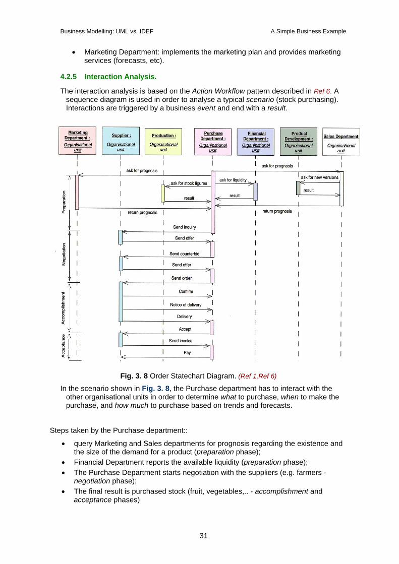
4.2.5 Interaction Analysis.
The interaction analysis is based on the Action Workflow pattern described in Ref 6. A sequence diagram is used in order to analyse a typical scenario (stock purchasing). Interactions are triggered by a business event and end with a result.
Fig. 3. 8 Order Statechart Diagram. (Ref 1,Ref 6)
In the scenario shown in Fig. 3. 8, the Purchase department has to interact with the other organisational units in order to determine what to purchase, when to make the purchase, and how much to purchase based on trends and forecasts.
Steps taken by the Purchase department::
• query Marketing and Sales departments for prognosis regarding the existence and the size of the demand for a product (preparation phase);
• Financial Department reports the available liquidity (preparation phase); • The Purchase Department starts negotiation with the suppliers (e.g. farmers -
negotiation phase); • The final result is purchased stock (fruit, vegetables,.. - accomplishment and
acceptance phases)
31
Business Modelling: UML vs. IDEF A Simple Business Example
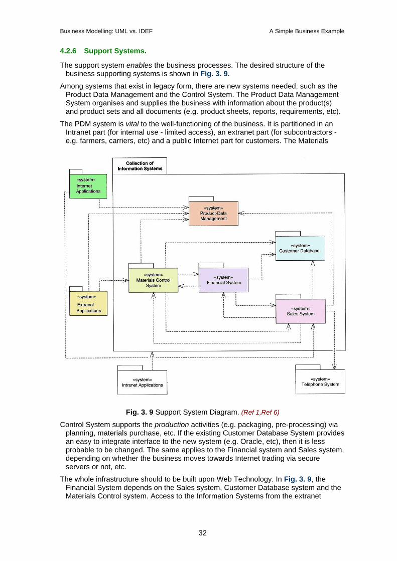
4.2.6 Support Systems.
The support system enables the business processes. The desired structure of the business supporting systems is shown in Fig. 3. 9.
Among systems that exist in legacy form, there are new systems needed, such as the Product Data Management and the Control System. The Product Data Management System organises and supplies the business with information about the product(s) and product sets and all documents (e.g. product sheets, reports, requirements, etc).
The PDM system is vital to the well-functioning of the business. It is partitioned in an Intranet part (for internal use - limited access), an extranet part (for subcontractors - e.g. farmers, carriers, etc) and a public Internet part for customers. The Materials
Fig. 3. 9 Support System Diagram. (Ref 1,Ref 6)
Control System supports the production activities (e.g. packaging, pre-processing) via planning, materials purchase, etc. If the existing Customer Database System provides an easy to integrate interface to the new system (e.g. Oracle, etc), then it is less probable to be changed. The same applies to the Financial system and Sales system, depending on whether the business moves towards Internet trading via secure servers or not, etc.
The whole infrastructure should to be built upon Web Technology. In Fig. 3. 9, the Financial System depends on the Sales system, Customer Database system and the Materials Control system. Access to the Information Systems from the extranet
32
Business Modelling: UML vs. IDEF A Simple Business Example
(reserved for subcontractors / VE participants) and Internet applications has to be restricted.
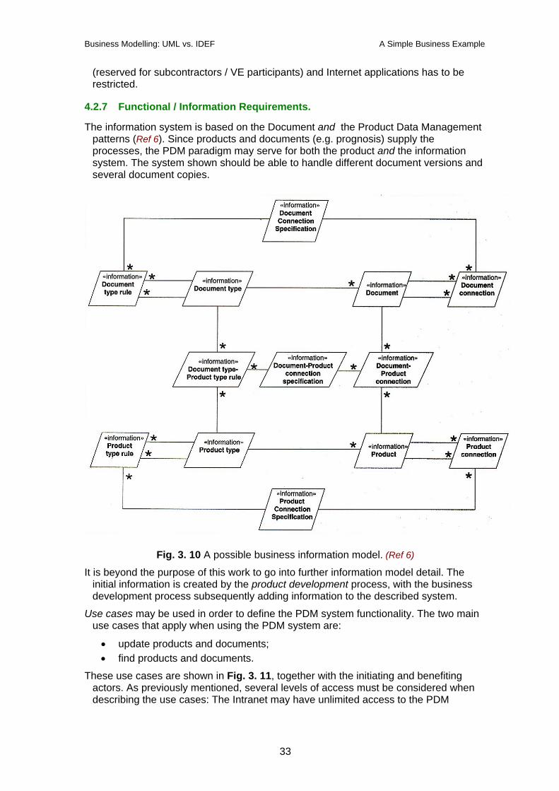
4.2.7 Functional / Information Requirements.
The information system is based on the Document and the Product Data Management patterns (Ref 6). Since products and documents (e.g. prognosis) supply the processes, the PDM paradigm may serve for both the product and the information system. The system shown should be able to handle different document versions and several document copies.
Fig. 3. 10 A possible business information model. (Ref 6)
It is beyond the purpose of this work to go into further information model detail. The initial information is created by the product development process, with the business development process subsequently adding information to the described system.
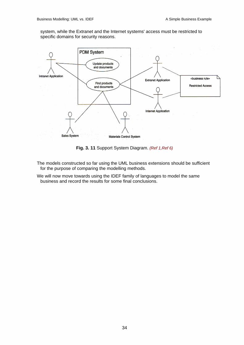
Use cases may be used in order to define the PDM system functionality. The two main use cases that apply when using the PDM system are:
• update products and documents; • find products and documents.
These use cases are shown in Fig. 3. 11, together with the initiating and benefiting actors. As previously mentioned, several levels of access must be considered when describing the use cases: The Intranet may have unlimited access to the PDM
33
Business Modelling: UML vs. IDEF A Simple Business Example
system, while the Extranet and the Internet systems' access must be restricted to specific domains for security reasons.
Fig. 3. 11 Support System Diagram. (Ref 1,Ref 6)
The models constructed so far using the UML business extensions should be sufficient for the purpose of comparing the modelling methods.
We will now move towards using the IDEF family of languages to model the same business and record the results for some final conclusions.
34
Business Modelling: UML vs. IDEF A Simple Business Example
4.3 The IDEF model.
The IDEF languages models applicable to the business under consideration would be IDEF0, IDEF1 / IDEF1x, IDEF2, IDEF3 and IDEF4.
4.3.1 IDEF0.
IDEF0 allows the function modelling of a business. Therefore, we will attempt to model the business processes from Fig. 3. 4, i.e. the Market Development, Business Development, Management Process, Product, Production and Subcontractor Development and Delivery processes. We will start with the Level 0 diagram and then detail it further until a sufficient degree of granularity is achieved.
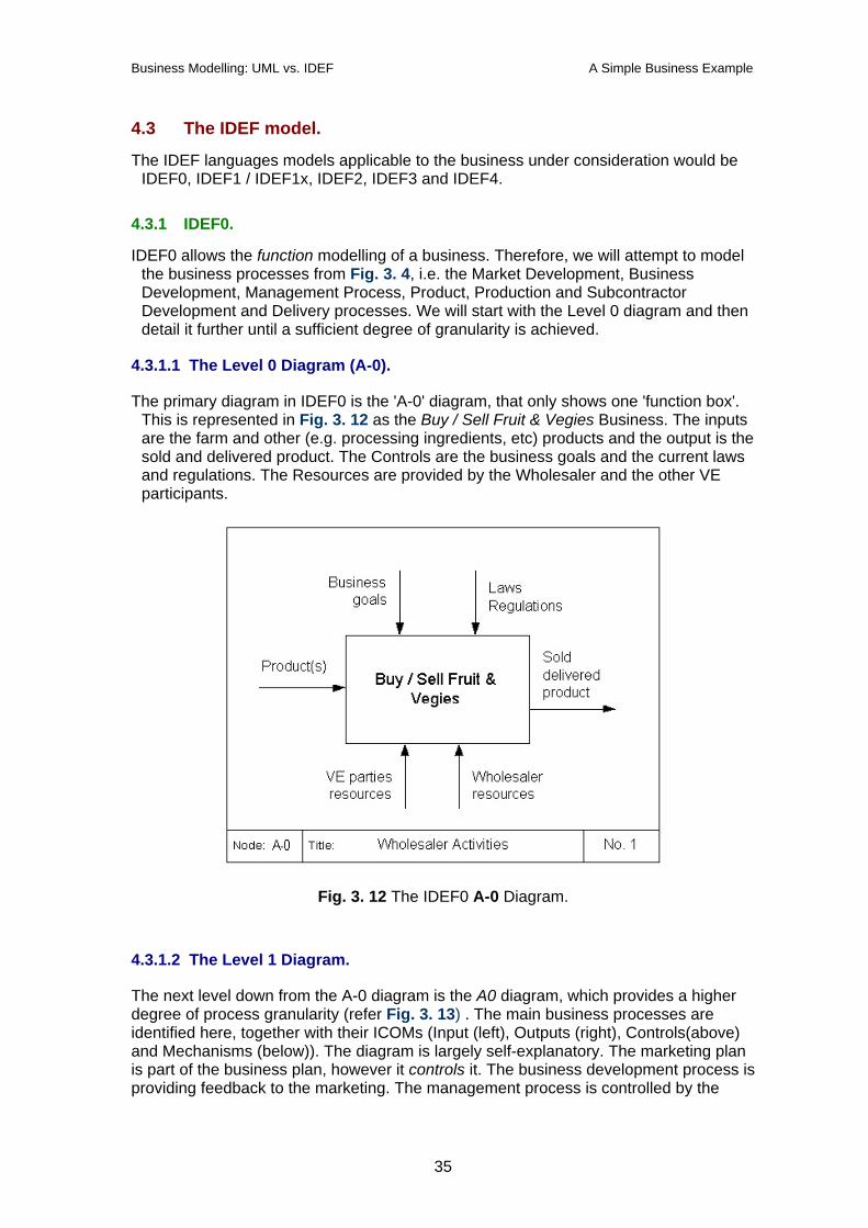
4.3.1.1 The Level 0 Diagram (A-0).
The primary diagram in IDEF0 is the 'A-0' diagram, that only shows one 'function box'. This is represented in Fig. 3. 12 as the Buy / Sell Fruit & Vegies Business. The inputs are the farm and other (e.g. processing ingredients, etc) products and the output is the sold and delivered product. The Controls are the business goals and the current laws and regulations. The Resources are provided by the Wholesaler and the other VE participants.
Fig. 3. 12 The IDEF0 A-0 Diagram.
4.3.1.2 The Level 1 Diagram.
The next level down from the A-0 diagram is the A0 diagram, which provides a higher degree of process granularity (refer Fig. 3. 13) . The main business processes are identified here, together with their ICOMs (Input (left), Outputs (right), Controls(above) and Mechanisms (below)). The diagram is largely self-explanatory. The marketing plan is part of the business plan, however it controls it. The business development process is providing feedback to the marketing. The management process is controlled by the
35
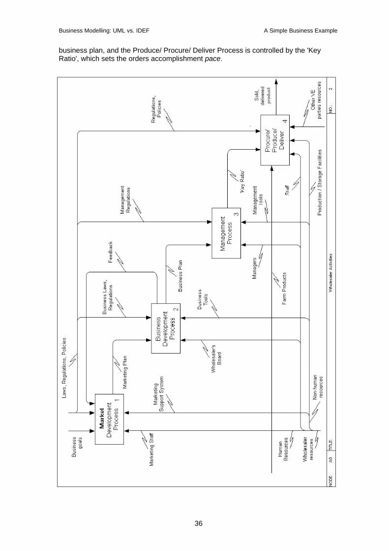
Business Modelling: UML vs. IDEF A Simple Business Example
business plan, and the Produce/ Procure/ Deliver Process is controlled by the 'Key Ratio', which sets the orders accomplishment pace.
36

Business Modelling: UML vs. IDEF A Simple Business Example
Fig. 3. 13 The IDEF0 A0 (level 1) Diagram.
4.3.1.3 Level 2 Diagram.
Starting from the A 0 diagram, any function (box on the diagram) may be selected for further detailing. Process #4 (Procure / Produce / Deliver) has been chosen because is promises to be the most dynamic and interesting - it is the equivalent of the real-time level in a decision diagram (e.g. GRAI-Grid), as opposed to the strategic / tactical level which are happening at a slower pace. The diagram is shown in Fig. 3. 14.
37
Business Modelling: UML vs. IDEF A Simple Business Example
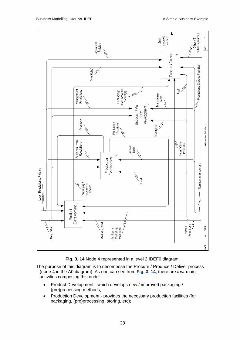
Fig. 3. 14 Node 4 represented in a level 2 IDEF0 diagram.
The purpose of this diagram is to decompose the Procure / Produce / Deliver process (node 4 in the A0 diagram). As one can see from Fig. 3. 14, there are four main activities composing this node:
• Product Development - which develops new / improved packaging / (pre)processing methods;
• Production Development - provides the necessary production facilities (for packaging, (pre)processing, storing, etc);
38
Business Modelling: UML vs. IDEF A Simple Business Example
• Subcontractor / VE party Development - maintains appropriate relationships with the subcontractors or the other Virtual Enterprise components in order to ensure availability and timely delivery of products;
• Procure / Deliver - actually purchases and delivers the product to the client.
The last activity will be again detailed in the next diagram, since it contains the most dynamic (and therefore complex) components of the business.
4.3.1.4 The Level 3 Diagram.
The node numbering concept used in IDEF0 diagrams aims to ensure that diagrams at any level of abstraction may be understood in isolation and their 'parents' may be easily found if necessary. For example, node 4 from the IDEF0 A 4 Diagram (refer Fig. 3. 14) is further detailed in the IDEF0 A 4.4 Diagram shown in Fig. 3. 15.
Node 4.4 means: it is activity number 4 of another activity number 4, shown on the main A0 diagram. Hence the 'parent' can readily be found by reading the '4.4' symbol alone.
The following activities are shown in the Node 4.4 diagram:
• Customer Interaction: it is a recurring activity, accomplished by the Sales department which constantly looks for new customer orders and promotes new products, etc;
• Procurement Process: one of the most important activities. It has to ensure that there is a demand for a given product, that enough product has been sold and the product delivery will be (just) on time. If there is any in-house product activity component (e.g. packaging, processing), Procurement also has to ensure the availability of those components (e.g. processed products).
• Delivery: Once the product is processed, packaged, etc and ready to deliver, this activity ensures the prompt (just-in-time if required) delivery either by own or shared VE resources.
As can be seen from the A 4.4 diagram, further detailing for the components of this node is not really necessary. The process of decomposition stops when the activities shown are fully understood.
39
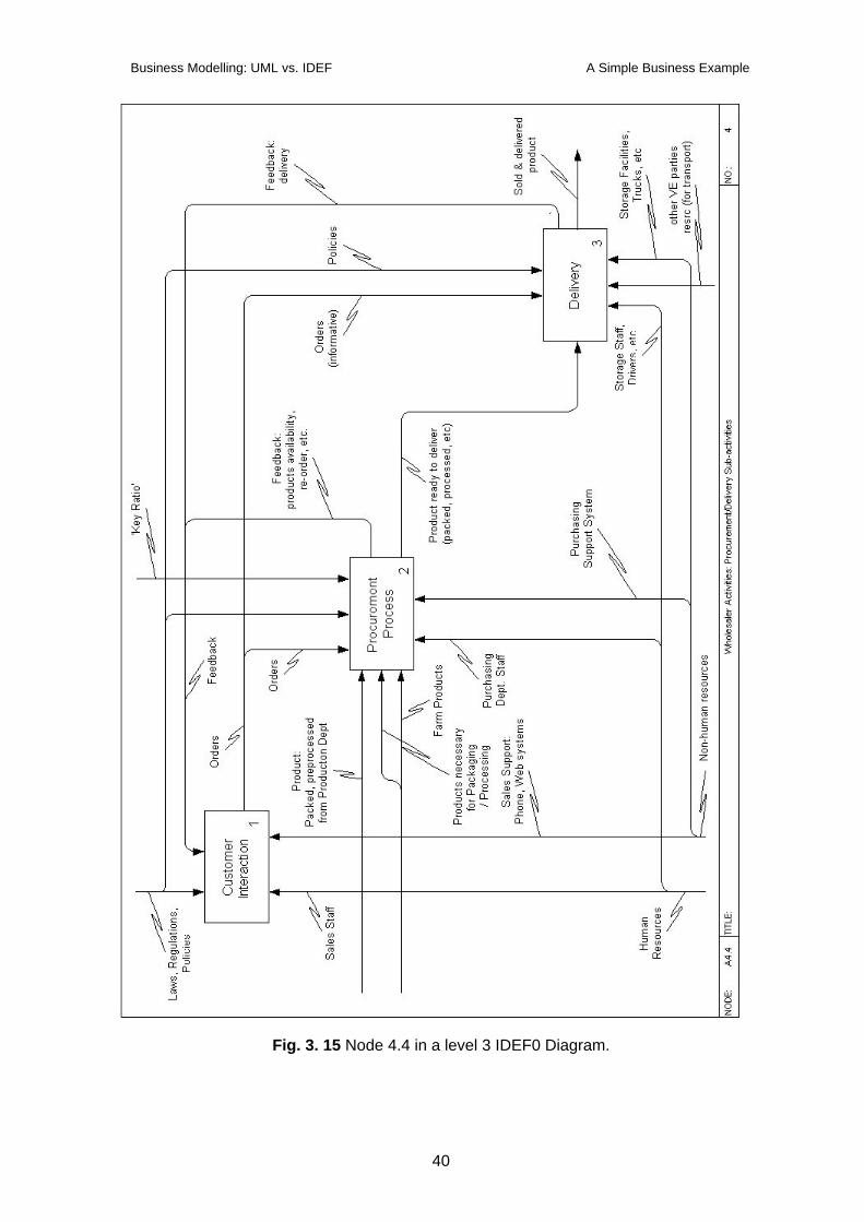
Business Modelling: UML vs. IDEF A Simple Business Example
Fig. 3. 15 Node 4.4 in a level 3 IDEF0 Diagram.
40
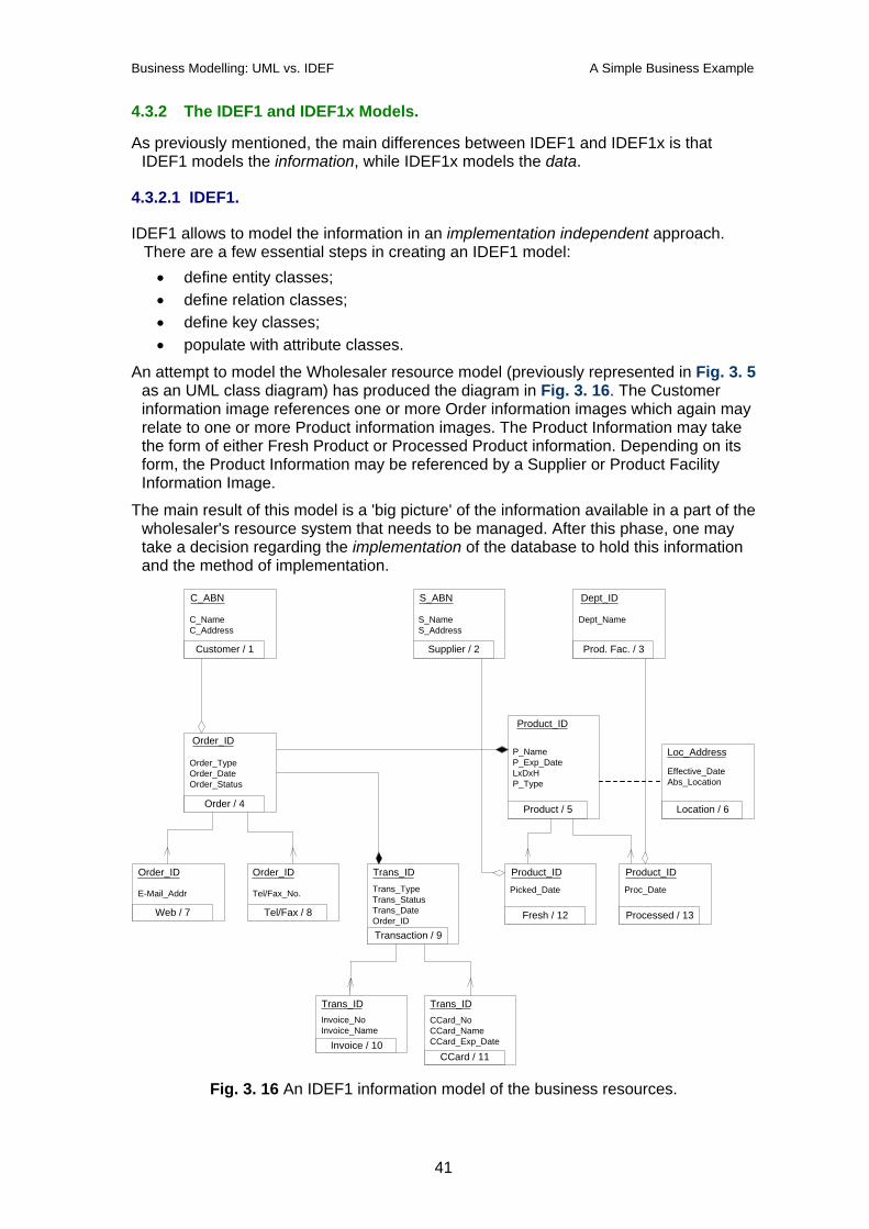
Business Modelling: UML vs. IDEF A Simple Business Example
4.3.2 The IDEF1 and IDEF1x Models.
As previously mentioned, the main differences between IDEF1 and IDEF1x is that IDEF1 models the information, while IDEF1x models the data.
4.3.2.1 IDEF1.
IDEF1 allows to model the information in an implementation independent approach. There are a few essential steps in creating an IDEF1 model: • define entity classes; • define relation classes; • define key classes; • populate with attribute classes.
An attempt to model the Wholesaler resource model (previously represented in Fig. 3. 5 as an UML class diagram) has produced the diagram in Fig. 3. 16. The Customer information image references one or more Order information images which again may relate to one or more Product information images. The Product Information may take the form of either Fresh Product or Processed Product information. Depending on its form, the Product Information may be referenced by a Supplier or Product Facility Information Image.
The main result of this model is a 'big picture' of the information available in a part of the wholesaler's resource system that needs to be managed. After this phase, one may take a decision regarding the implementation of the database to hold this information and the method of implementation.
Invoice_NoInvoice_Name
C_NameC_Address
Customer / 1
C_ABN
P_NameP_Exp_DateLxDxHP_Type
Product / 5
Product_ID
S_NameS_Address
Supplier / 2
S_ABN
Order_TypeOrder_DateOrder_Status
Order / 4
Order_ID
Dept_Name
Prod. Fac. / 3
Dept_ID
Effective_DateAbs_Location
Location / 6
Loc_Address
Tel/Fax_No.
Tel/Fax / 8
Order_ID
E-Mail_Addr
Web / 7
Order_IDTrans_TypeTrans_StatusTrans_DateOrder_IDTransaction / 9
CCard_NoCCard_NameCCard_Exp_Date
CCard / 11
Trans_ID
Invoice / 10
Trans_ID
Trans_ID
Picked_Date
Fresh / 12
Product_ID
Proc_Date
Processed / 13
Product_ID
Fig. 3. 16 An IDEF1 information model of the business resources.
41
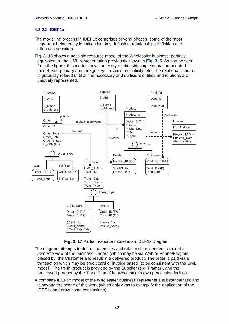
Business Modelling: UML vs. IDEF A Simple Business Example
4.3.2.2 IDEF1x.
The modelling process in IDEF1x comprises several phases, some of the most important being entity identification, key definition, relationships definition and attributes definition.
Fig. 3. 18 shows a possible resource model of the Wholesaler business, partially equivalent to the UML representation previously shown in Fig. 3. 5. As can be seen from the figure, this model shows an entity relationship implementation oriented model, with primary and foreign keys, relation multiplicity, etc. The relational schema is gradually refined until all the necessary and sufficient entities and relations are uniquely represented.
Customer
C_ABN
C_NameC_Address
Supplier
S_ABN
S_NameS_Address
Prod. Fac.
Dept_ID
Dept_NameProduct
Product_ID
Order_ID (FK)P_NameP_Exp_DateLxDxHP_Type
Order
Order_ID
Order_TypeOrder_DateOrder_StatusC_ABN (FK)
Location
Loc_Address
Product_ID (FK)Effective_DateAbs_Location
Web
Order_ID (FK)
E-Mail_Addr
Order_Type
Tel / Fax
Order_ID (FK)
Tel/Fax_No.
P_Type
Fresh
Product_ID (FK)
S_ABN (FK)Picked_Date
Processed
Product_ID (FK)
Dept_ID (FK)Proc_Date
has an
placesan
supplies
produces
Transaction
Order_ID (FK)Trans_ID
Trans_DateTrans_StatusTrans_Type
Trans_Type
Credit_Card
Order_ID (FK)Trans_ID (FK)
CCard_No.CCard_NameCCard_Exp_Date
Invoice
Order_ID (FK)Trans_ID (FK)
Invoice_NoInvoice_Name
results in a delivered
paid with
1
P
P
Fig. 3. 17 Partial resource model in an IDEF1x Diagram.
The diagram attempts to define the entities and relationships needed to model a resource view of the business. Orders (which may be via Web or Phone/Fax) are placed by the Customer and result in a delivered product. The order is paid via a transaction which may be credit card or invoice based (to be consistent with the UML model). The fresh product is provided by the Supplier (e.g. Framer), and the processed product by the 'Food Plant' (the Wholesaler's own processing facility).
A complete IDEF1x model of the Wholesaler business represents a substantial task and is beyond the scope of this work (which only aims to exemplify the application of the IDEF1x and draw some conclusions).
42
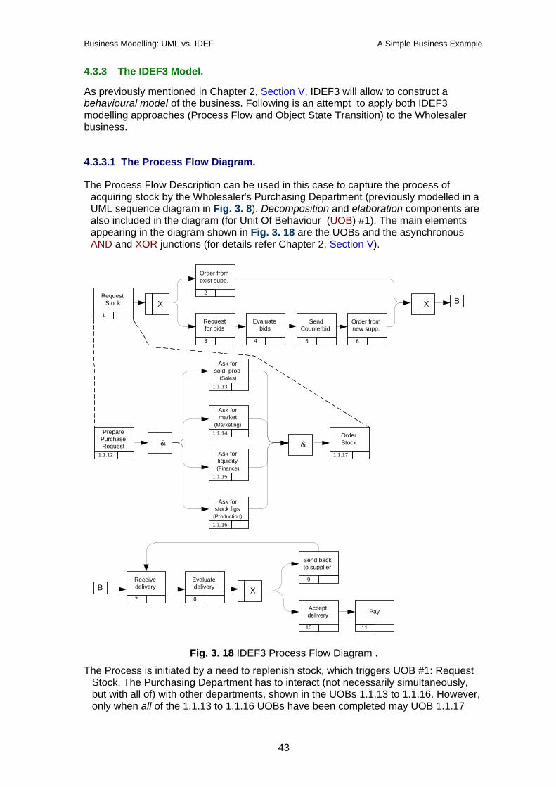
Business Modelling: UML vs. IDEF A Simple Business Example
4.3.3 The IDEF3 Model.
As previously mentioned in Chapter 2, Section V, IDEF3 will allow to construct a behavioural model of the business. Following is an attempt to apply both IDEF3 modelling approaches (Process Flow and Object State Transition) to the Wholesaler business.
4.3.3.1 The Process Flow Diagram.
The Process Flow Description can be used in this case to capture the process of acquiring stock by the Wholesaler's Purchasing Department (previously modelled in a UML sequence diagram in Fig. 3. 8). Decomposition and elaboration components are also included in the diagram (for Unit Of Behaviour (UOB) #1). The main elements appearing in the diagram shown in Fig. 3. 18 are the UOBs and the asynchronous AND and XOR junctions (for details refer Chapter 2, Section V).
1
&
RequestStock
1.1.13
Ask forsold prod
(Sales)
1.1.14
Ask formarket
(Marketing)
1.1.15
Ask forliquidity(Finance)
1.1.16
Ask forstock figs
(Production)
1.1.17
&OrderStock
X2
Order fromexist supp.
3
Requestfor bids
4
Evaluatebids
X
5
SendCounterbid
6
Order fromnew supp.
7
Receivedelivery
8
Evaluatedelivery X
9
Send backto supplier
10
Acceptdelivery
11
Pay
B
B
1.1.12
PreparePurchaseRequest
Fig. 3. 18 IDEF3 Process Flow Diagram .
The Process is initiated by a need to replenish stock, which triggers UOB #1: Request Stock. The Purchasing Department has to interact (not necessarily simultaneously, but with all of) with other departments, shown in the UOBs 1.1.13 to 1.1.16. However, only when all of the 1.1.13 to 1.1.16 UOBs have been completed may UOB 1.1.17
43
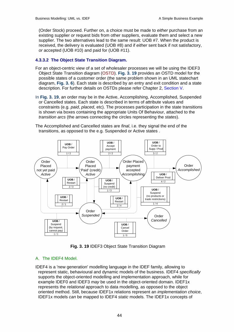
Business Modelling: UML vs. IDEF A Simple Business Example
(Order Stock) proceed. Further on, a choice must be made to either purchase from an existing supplier or request bids from other suppliers, evaluate them and select a new supplier. The two alternatives lead to the same result: UOB #7. When the product is received, the delivery is evaluated (UOB #8) and if either sent back if not satisfactory, or accepted (UOB #10) and paid for (UOB #11).
4.3.3.2 The Object State Transition Diagram.
For an object-centric view of a set of wholesaler processes we will be using the IDEF3 Object State Transition diagram (OSTD). Fig. 3. 19 provides an OSTD model for the possible states of a customer order (the same problem shown in an UML statechart diagram, Fig. 3. 6). Each state is described by an entry and exit condition and a state description. For further details on OSTDs please refer Chapter 2, Section V.
In Fig. 3. 19, an order may be in the Active, Accomplishing, Accomplished, Suspended or Cancelled states. Each state is described in terms of attribute values and constraints (e.g. paid, placed, etc). The processes participation in the state transitions is shown via boxes containing the appropriate Units Of Behaviour, attached to the transition arcs (the arrows connecting the circles representing the states).
The Accomplished and Cancelled states are final, i.e. they signal the end of the transitions, as opposed to the e.g. Suspended or Active states .
UOB /CancelOrder1 / 5
OrderPlaced
not yet paidActive
OrderPlaced
'Paid' (credit)Active
Order Placedpaymentaccepted
Accomplishing
OrderAccomplished
OrderSuspended Order
Cancelled
UOB /Order to
Supp / Prod3 / 2
UOB /Accept
payment2 / 2
UOB /Pay Order
1 / 2
UOB /Suspend
(by request,cannot pay)
1 / 1
UOB /Restart
2 / 1
UOB /Restart
2 / 3
UOB /Restart
2 / 4
UOB /Deliver Prod
4 / 2
UOB /Suspend
(no products ortrade restrictions)
1 / 4
UOB /Suspend
(no credit)1 / 3
Fig. 3. 19 IDEF3 Object State Transition Diagram
A. The IDEF4 Model.
IDEF4 is a 'new generation' modelling language in the IDEF family, allowing to represent static, behavioural and dynamic models of the business. IDEF4 specifically supports the object-oriented modelling and implementation approach, while for example IDEF0 and IDEF3 may be used in the object-oriented domain. IDEF1x represents the relational approach to data modelling, as opposed to the object oriented method. Still, because IDEF1x relations represent an implementation choice, IDEF1x models can be mapped to IDEF4 static models. The IDEF1x concepts of
44
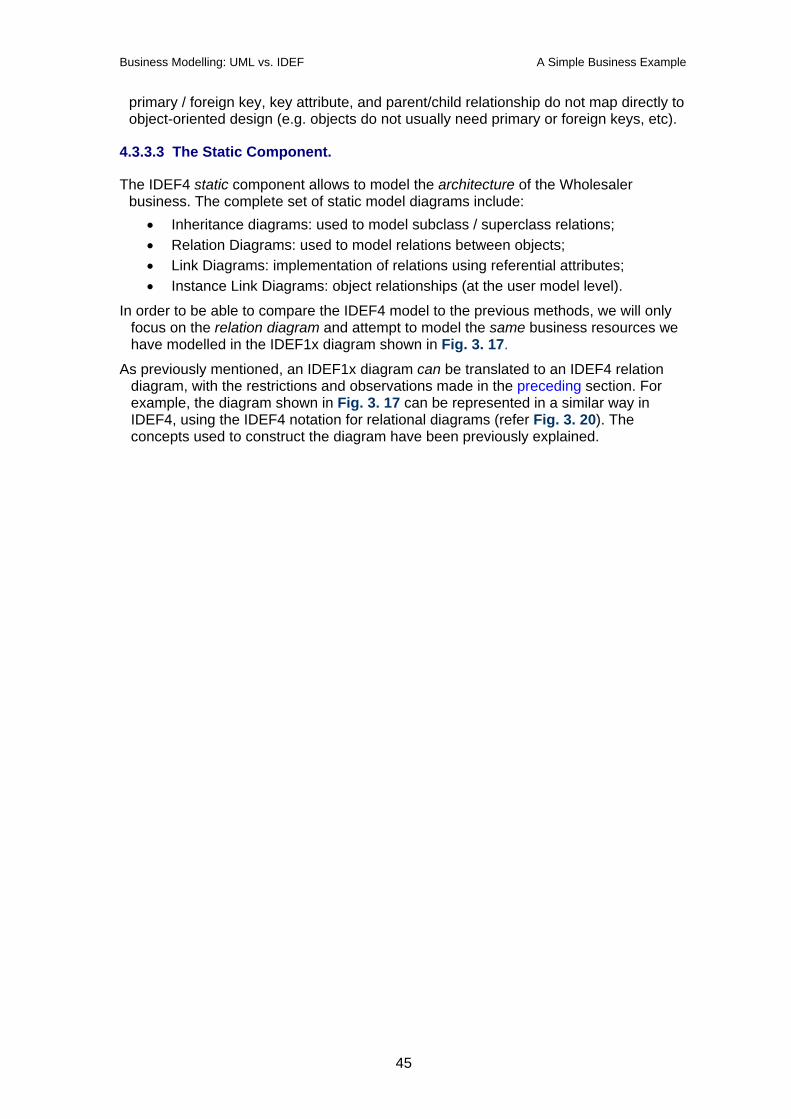
Business Modelling: UML vs. IDEF A Simple Business Example
primary / foreign key, key attribute, and parent/child relationship do not map directly to object-oriented design (e.g. objects do not usually need primary or foreign keys, etc).
4.3.3.3 The Static Component.
The IDEF4 static component allows to model the architecture of the Wholesaler business. The complete set of static model diagrams include:
• Inheritance diagrams: used to model subclass / superclass relations; • Relation Diagrams: used to model relations between objects; • Link Diagrams: implementation of relations using referential attributes; • Instance Link Diagrams: object relationships (at the user model level).
In order to be able to compare the IDEF4 model to the previous methods, we will only focus on the relation diagram and attempt to model the same business resources we have modelled in the IDEF1x diagram shown in Fig. 3. 17.
As previously mentioned, an IDEF1x diagram can be translated to an IDEF4 relation diagram, with the restrictions and observations made in the preceding section. For example, the diagram shown in Fig. 3. 17 can be represented in a similar way in IDEF4, using the IDEF4 notation for relational diagrams (refer Fig. 3. 20). The concepts used to construct the diagram have been previously explained.
45
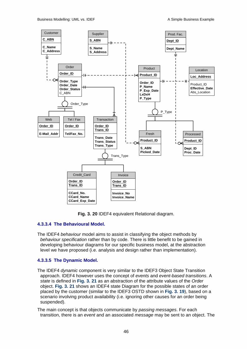
Business Modelling: UML vs. IDEF A Simple Business Example
Customer
C_ABN
C_NameC_Address
Supplier
S_ABN
S_NameS_Address
Prod. Fac.
Dept_ID
Dept_Name
Product
Product_ID
Order_IDP_NameP_Exp_DateLxDxHP_Type
Order
Order_ID
Order_TypeOrder_DateOrder_StatusC_ABN
Location
Loc_Address
Product_IDEffective_DateAbs_Location
Web
Order_ID
E-Mail_Addr
Order_Type
Tel / Fax
Order_ID
Tel/Fax_No.
P_Type
Fresh
Product_ID
S_ABNPicked_Date
Processed
Product_ID
Dept_IDProc_Date
Transaction
Order_IDTrans_ID
Trans_DateTrans_StatusTrans_Type
Trans_Type
Credit_Card
Order_IDTrans_ID
CCard_No.CCard_NameCCard_Exp_Date
Invoice
Order_IDTrans_ID
Invoice_NoInvoice_Name
Fig. 3. 20 IDEF4 equivalent Relational diagram.
4.3.3.4 The Behavioural Model.
The IDEF4 behaviour model aims to assist in classifying the object methods by behaviour specification rather than by code. There is little benefit to be gained in developing behaviour diagrams for our specific business model, at the abstraction level we have proposed (i.e. analysis and design rather than implementation).
4.3.3.5 The Dynamic Model.
The IDEF4 dynamic component is very similar to the IDEF3 Object State Transition approach. IDEF4 however uses the concept of events and event-based transitions. A state is defined in Fig. 3. 21 as an abstraction of the attribute values of the Order object. Fig. 3. 21 shows an IDEF4 state Diagram for the possible states of an order placed by the customer (similar to the IDEF3 OSTD shown in Fig. 3. 19), based on a scenario involving product availability (i.e. ignoring other causes for an order being suspended).
The main concept is that objects communicate by passing messages. For each transition, there is an event and an associated message may be sent to an object. The
46
Business Modelling: UML vs. IDEF A Simple Business Example
object reacts and changes its state. The arrows on the event / message relations in the diagram show the direction of the communication (if more detail on communication is needed, client-server diagrams may also be used).
Order
Status: CancelledProduct: Available
3: Cancelled Order
Status: ActiveProduct: Available
1: Active Order
Status: SuspendedProduct: Not available
1: Suspended
Order
Status: AccomplishedProduct: Delivered
3: Accomplished
(E1: place order)M1:
create
M2: checkproducts
(E2:update)
M9: delete
(E8:paid)
M8:accomplish
(E6:deactivate)
M6:cancel
(E7: remove)M7:delete
(E9: remove)
(E3:NOproducts)
M3:suspend
M5:restart (E5:
productavailable)
M4: checkproducts
(E4: update)
Fig. 3. 21 IDEF4 State diagram.
If an Order object exists, then it may be in one of the Active, Suspended, Cancelled or Accomplished states. An update event (e.g. E2) may send a message to the object to e.g. check products. If there are no products, the event E3 occurs and the message M3 is sent to the object. As a result, the object enters the Suspended status. Another example: if event E8 occurs (order has been paid), then the message M8 (accomplish) is sent to the object, which results in the object entering the Accomplished state, and so on. In the Message broadcasting approach, the messages are broadcasted to all objects but only the objects that have registered for certain events respond.
As a loose analogy to message broadcasting consider the following: in a classroom a teacher calls up a name. All students hear the message, but only one student that matches the name reacts. The others filter out the message. In the software domain it is usually the operating system - e.g. via a specialised daemon - that takes care of activating the registered processes.
IDEF4 is a complex language with many features and concepts, aiming to complement and go beyond the IDEF0 to IDEF3 languages. This paper has only made limited use of the IDEF4 language, in order to present its possibilities versus the other IDEF family members and the Unified Modelling Language.
4.4 A Comparison.
As a general conclusion, both the UML and IDEF approaches may be used to model almost any useful view of a business.
The IDEF language family has around 30 years of development and a few US governmental bodies behind it (e.g. Department of Defence, the US Air Force, etc). The newer additions, like IDEF4, 5 and up, address new or changed requirements.
UML is a 'young' modelling language compared to the IDEF, aimed mostly towards software development. It has been born not through competition, but via 'mergers' (i.e. the competitors have merged and 'won' ).The right timing and software design tool producers' support have determined its great appeal to the industry.
47
Business Modelling: UML vs. IDEF A Simple Business Example
As one can see from the examples presented, UML can only be effectively used when complemented by:
• design patterns - which allow design knowledge propagation and reuse; • specific extensions that allow to effectively capture the business processes.
It is rather odd that a language that includes nine different types of diagrams still needs extensions and lacks a knowledge base. The large number of diagram types (of which two are explicitly targeted at software development / deployment) originates from the way UML was created (methods unification) and does not seem to help a great deal once we get away from the software design realm.
On the positive side, UML is easy to learn and may introduce the interested users to advanced modelling concepts such as the meta-model. Users do not need to use all the diagrams and are free to implement their model any way they want.
IDEF0 models separate functions from organizations, but do not support the specification of a process, nor capture time-ordered constraints between activities. Also, a balance must be achieved between the level of abstraction represented by the boxes and the level expressed by the ICOMs' (arrows) . Also, as can be seen from the diagrams presented in Fig. 3. 12 through to Fig. 3. 15, IDEF0 does not represent the conditions necessary to enter or exit a process. That is why IDEF0 is best used in combination with other IDEF methods (e.g. IDEF3).
IDEF1 cannot be directly used in the implementation phase. However, as we have previously shown in Fig. 3. 16, it can be extremely useful in modelling the information within the business, free of implementation constraints.
IDEF1x is a good tool for the basis of database design, but does not follow the rules of good graphical design - its symbols do not cleanly map to the concepts they are supposed to model. For example, the solid dot can mean anything, depending on the context, and the same particular situation may be represented by more than one set of symbols (refer Fig. 3. 17 for an IDEF1x example). Furthermore, correcting one error in an IDEF1x diagram relationship usually triggers cascading changes.
Overly complex and cluttered IDEF3 diagrams may result from combining too many viewpoints and scenarios into a single diagram. IDEF3 is a description capture method and it is designed to be tolerant of partial and inconsistent descriptions. Very often those inconsistencies are the root of an organization's problems and they should be appropriately addressed in the IDEF3 representation and not polished or hidden.
The IDEF languages have been developed to answer three main requirements in enterprise (business) modelling:
• capture what is known about the real world and the relationships between people, events, etc;
• capture existing and future information management requirements; • supporting methods for design of systems answering the needs previously
identified.
IDEF3 Process Description Capture and IDEF5 Ontology Description methods address the first of these needs. The IDEF0 Function Modelling and the IDEF1 Information Modelling answer the second need (information management requirements). Finally, the IDEF1X Data Modelling, IDEF2 System Dynamics Modelling and IDEF4 Object-oriented Design were aimed at satisfying the third need.
48
Business Modelling: UML vs. IDEF Conclusions
5 Conclusions.
There is no such thing as a final solution or a universal tool. The challenge is not to find the ultimate tool, but the right tool for the job. The same applies to business modelling.
Business modelling has appeared as a response to the need to formalise the business processes, in order to allow conservation and reuse of the business knowledge. It is vital that an enterprise is resilient to the possible loss of core competencies (e.g. staff going to retirement, etc). This however can only be achieved if the business knowledge is formally gathered and organised within a well-defined framework.
In today's competitive world, a business that doesn't continuously strive to improve its efficiency ('better products at lower costs' is just the tip of the iceberg) cannot expect to last very long.
Therefore, another important aspect in the life of a business is change. Long term forecasts are increasingly hard to make in an ever faster changing environment. As a result, an enterprise (a business) must not only quickly adapt to change but also continuously evolve. In these conditions, change becomes more of a permanent internal process rather than an external factor the enterprise has to adapt to.
Business modelling has its origins in CIM (computer-integrated manufacturing). The early work in this domain was mainly confined to the manufacturing or the computer / information handling. However, it has become clear that the concepts formulated actually applied to any enterprise and any system within the enterprise.
A substantial amount of progress has been recorded in the development of software design tools and methods. While the software is part of the business and it is intended to support it, too many times it does not reflect its real needs. Among other reasons, a major cause has to be modelling and implementing the information system separately from the business it must support. Hence the ideas to: • use the software development tools / methods for business modelling (with
appropriate changes / extensions); • use the business model as a template for the software development
requirements.
In this paper we have looked at two main methods that strive to fulfil the two above-mentioned ideas. The two methods appeal to different groups of people. Each method has its advantages and downsides, but exhibit the same trend: the attempt to cover the other method's traditional domains.
IDEF is coming from the manufacturing / information environment and aims to cover object orientation, knowledge representation and software development.
UML is still in its infancy; it comes from the domain of object-oriented software development but there are increasing efforts to extend it towards business process modelling.
Which method ? It is up to the user: the task, background, resources, patterns… will all play a role in selecting the right tool for the job.
49
Business Modelling: UML vs. IDEF References
6 References. 1. Craig Larman(1998) Applying UML and patterns, Prentice-Hall, Upper Saddle River
NJ, ISBN 0-13-748880-7
2. Sinan Si Alhir, (1998) UML in a Nutshell, O'Reilly & Associates, Sebastopol, CA, ISBN 1-56592-448-7
3. Sinan Si Alhir, The Object Oriented Paradigm, PDF document, Oct 1998
4. Sinan Si Alhir, The Unified Modelling Language - Two years after adoption of the Standard, PDF document, Nov 1998
5. Sinan Si Alhir, Understanding the UML, 'Methods and Tools' (software engineering newsletter), Apr 1999
6. Eriksson Hans-Erik et al, Business Modelling with UML, John Wiley & Sons, New York, NY, ISBN 0-471-29551-5
7. Murray Cantor (1998) Object-Oriented Project Management with UML, John Wiley & Sons, ISBN 0-471-25303-0
8. Vernadat, F. B.: Enterprise Modelling and Integration, Chapman & Hall, London (1995) ISBN 0-412-60550-3
9. Chris Kobryn, UML 2001: A Standardisation Odyssey, Communications of the ACM, October 1999.
10. Mary Shaw, David Garlan, Software Architecture - Perspectives on a Emerging Discipline, Prentice Hall Upper Saddle River, NJ (1996) ISBN 0-13-182957-2
11. ISO15704 (1999) ISO/DIS 15704: Industrial automation systems - Requirements for enterprise-reference architectures and methodologies. ISO/TC184/SC5/WG1
12. R.J.Mayer: IDEF Family of Languages Overview and Practical Guidelines for IDEF use - paper on the IDEF web site: http://www.idef.com/complete_reports
13. R. Panrahan et al.: The IDEF Modelling Methodology - paper on the URL: http://stsc.hill.af.mil/CrossTalk/1995/jun/IDEF.asp
14. O. Noran, VITE: The Fruit and Vegetable Virtual Enterprise, Enterprise Integration Assignment paper, Griffith University, November 1999, available on http://www.cit.gu.edu.au/~noran/cit_6118
15. Chris Marshall, Enterprise Modelling with UML - Designing Successful Software through Business Analysis, Addison-Wesley Reading, Massachusetts (2000) ISBN 0-201-43313-3
50