Embed Size (px)
Citation preview

Trenchless Technology-Pipe Jacking

Contents
• Introduction to pipe jacking• About the Technique• Drive lengths and diameters• Jacking loads• Jacking pipe materials• Guidance and controls• Site investigation and ground conditions• Comparison with open trench and segmental
tunnels – H&S, environmental and technical benefits

What is Pipe Jacking
• According to PJA, UK
“Pipe jacking is a technique for installing underground pipelines, ducts and culverts. Powerful hydraulic jacks are used to push specially designed pipes through the ground behind a shield at the same time as excavation is taking place with the shield”

Common Applications
• Sewerage and potable water construction
• Gas and water utilities
• Industrial pipelines (e.g. oil, chemical etc)
• Electricity and telecom utilities
• Pedestrian subways

About the technique
• Pipes are pushed through the ground behind the shield using
powerful jacks.
• Simultaneously excavation takes place within the shield.
• This process is continued until the pipeline is completed.
• The method provides a flexible, structural, watertight,
finished pipeline as the tunnel is excavated.
• No theoretical limit to the length of individual pipelines.

About the technique
• Pipes range from 150mm to 3000mm diameter can be
installed in straight line or in curvature.
• Thrust wall is provided for the reaction of the jacks.
• In case of poor soil, the thrust wall may punch inside the
soil, then piles or ground anchoring methods can be
used.

Procedure
• The thrust pit and the reception pit are excavated at the
required places.
• Then the thrust wall is set up in the thrust pit according to the
requirement.
• In case of mechanized excavations, a very large pit is required.
• But in case of manual excavation, a small pit is enough.
• Thrust ring is provided to ensure the even distribution of
stress along the circumference of the pipe.

• The number of jacks vary upon the frictional resistance of the
soil, strength of pipes etc.
• The size of the reception pit is to be big enough to receive the
jacking shield.
• To maintain the accuracy of alignment a steer-able shield is
used during the pipe jacking.
• In case of small and short distance excavations, ordinary
survey method is sufficient.
• But in case of long excavations, remote sensing and other
techniques can be used.
Procedure

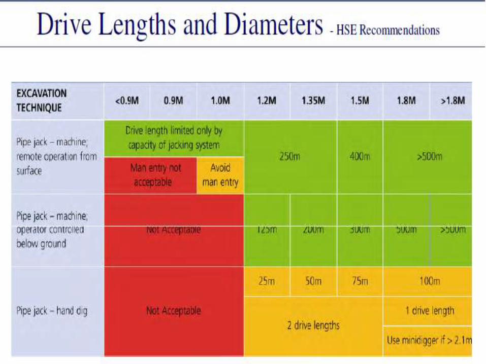

Jacking Loads - Capacity
Ultimate jacking load dependent upon:-• Pipe load capacity• Jacking wall / restraint capacity• Diameter, length & weight of pipes• Ground & groundwater conditions• Excavation method & control• Cycle times / working patterns• Alignment control• Maintaining annulus• Lubrication• Main jacking station capacity• Intermediate jacking stations (number /capacity)

Jacking Loads - Reduction & Control
Good practice should include:-• Correct choice of excavation method
Open, EPB, slurry• Control of groundwater
Dewatering, ground treatment• Good alignment control & correction
1º = 50 to 90% reduction in pipe capacity• Maintenance of cut annulus
Cut diameter, TBM / shield over-cut• Good lubrication
Injection points, Bentonite, water & polymers• Correct choice of intermediate jacking stations
Number required, capacity & position

Jacking Pipe Materials
• Concrete jacking pipes
BS EN 1916
• Clay pipes:
BS EN 296-7 & BS EN 12899: 2000
• Steel pipes
• GRP pipes

Guidance & Control
• Continuous & real-time
• Normally laser guidance
• Maintains accuracy
• Line, level & altitude
• Permits remote operation
• Camera targets
• Giro compass (curves etc.)


Comparison with Open Trench / Segmental Tunnelling
Technical aspectComparison with Open Trench1. Minimal surface disruption and reinstatement2. Fewer utility diversionsComparison with Segmental Tunneling1. Inherent strength of pipeline2. Smooth internal finish3. No secondary lining4. Less joints5. Watertight6. Control of settlement

Comparison with Open Trench
Environmental Aspect
1. Avoid damage to services
2. Reduced disruption
3. Maintains highway integrity
4. Carbon footprint
• 90% fewer vehicle movements
• Less spoil
• Less quarried material
Additional Applications
Box Sections
• Subways
• Roadways
Other uses
• jacked arches
• bridge slide foundations

Summary
• Engineering integrity• Low capital costs• Low maintenance• Cost-effective• Safe installation• Environmental benefits• Extensively used worldwide• 0.45m to 3m diameters• Long drive lengths• Good engineering performance

Thank you.