Embed Size (px)
DESCRIPTION
Citation preview

A Presentation on:Electrification on “Malda Polytechnic”:Planning & Designing of Distribution System

Project Members:Sourav DasMilan kr DasSantu MajeeUjjwal MaitiSantu MaitiPratim ChakraborttyDebabrata KarmakarSubho MondalAnimesh KanrarJahir MallickManas Adak
Planning of Distribution System A distribution system deals with the
distribution of electrical energy. A good system planning should provide for an orderly development of the system to meet the power requirements for a period of about five years and to obtain optimum benefit from the available resources. The main purpose of planning is:
To make the system economical while conforming to the Indian electricity rules.
To minimize losses and maintain regulation within permissible limits. For proper Planning of a distribution system. Load survey and load forecasting of the area is necessary.

* Load Survey * The load survey of a particular area is carried out to find present
load requirement as well as the expected load growth over a period of 5 to 7 years.
The following basic data should be collected for starting this work:
A detailed map of the area showing important features. The number of houses, population and the new construction
anticipated the area. The expected number of shops post-office, rural health center
Panchayat office etc. Details of hospital s, railway stations, public health sewage systems
and water supply schemes. The cultivated area, number of wells, available irrigation facilities
and irrigated area. The type of industries and number of industries possible in these
areas. Development programs implemented and envisaged in the area.

* Load Calculation of Hostel * 1st Year Block 10.48 kW 2nd Year Block 12.21 kW 3rd Year Block 12.21 kW Common Room 0.883 kW Dining Room 0.883 kW

* Load Calculation of Nodal Office *
Regional Office 9.004 kW
VET Office 2.667 kW
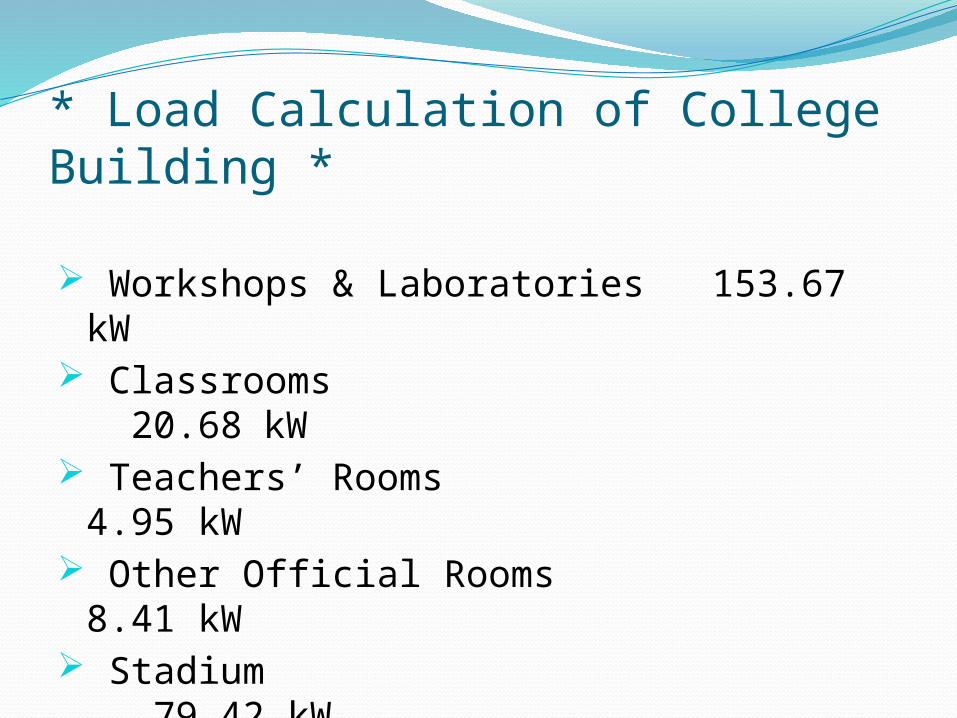
* Load Calculation of College Building *
Workshops & Laboratories 153.67 kW Classrooms 20.68 kW Teachers’ Rooms 4.95 kW Other Official Rooms 8.41 kW Stadium 79.42 kW

* Demand Factors * Single Storied → 0.8 Public Building → 0.8 Double Storied → 0.7 Commercial Building → 0.9 Triple Storied → 0.6 Cinema Hall → 0.9 Multi Storied → 0.8 Industry → 0.8 Street Light → 1.0
Public Fan → 0.9 Domestic Fan → 0.3 to 0.6 Domestic Light → 0.3 to 0.6 Public Light → 0.8 to 0.9 Commercial Light → 0.5 to 0.75 Industrial Motor → 0.95 Pump Motor → 0.95
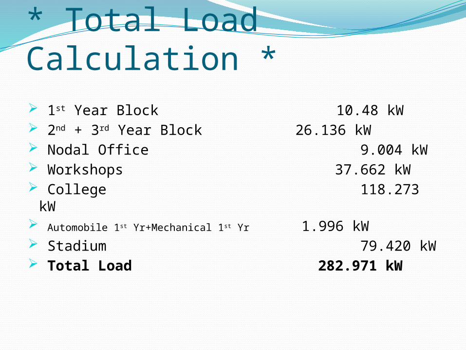
* Total Load Calculation * 1st Year Block 10.48 kW 2nd + 3rd Year Block 26.136 kW Nodal Office 9.004 kW Workshops 37.662 kW College 118.273 kW Automobile 1st Yr+Mechanical 1st Yr 1.996 kW Stadium 79.420 kW Total Load 282.971 kW
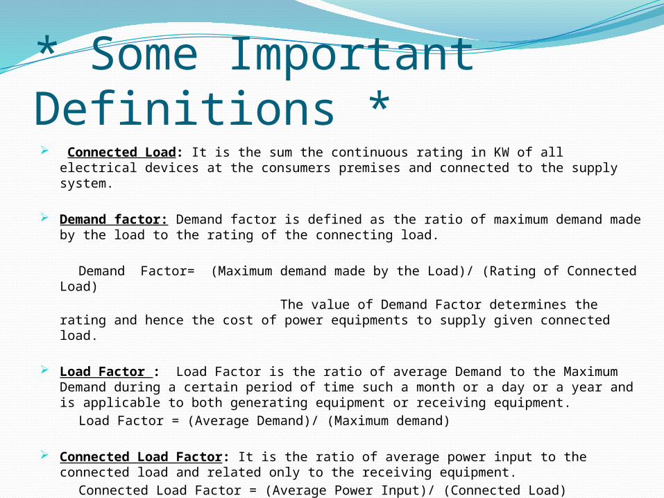
* Some Important Definitions * Connected Load: It is the sum the continuous rating in KW of all electrical devices at
the consumers premises and connected to the supply system.
Demand factor: Demand factor is defined as the ratio of maximum demand made by the load to the rating of the connecting load.
Demand Factor= (Maximum demand made by the Load)/ (Rating of Connected Load) The value of Demand Factor determines the rating and hence the cost of
power equipments to supply given connected load.
Load Factor : Load Factor is the ratio of average Demand to the Maximum Demand during a certain period of time such a month or a day or a year and is applicable to both generating equipment or receiving equipment.
Load Factor = (Average Demand)/ (Maximum demand)
Connected Load Factor: It is the ratio of average power input to the connected load and related only to the receiving equipment.
Connected Load Factor = (Average Power Input)/ (Connected Load)
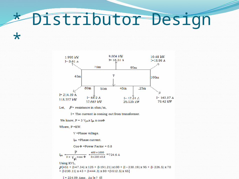
* Distributor Design *
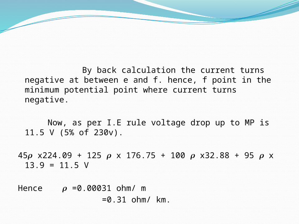
By back calculation the current turns negative at between e and f. hence, f point in the minimum potential point where current turns negative.
Now, as per I.E rule voltage drop up to MP is 11.5 V (5% of 230v).
45 x224.09 + 125 x 176.75 + 100 x32.88 + 95 𝝆 𝝆 𝝆 𝝆x 13.9 = 11.5 V
Hence =0.00031 ohm/ m𝝆 =0.31 ohm/ km.
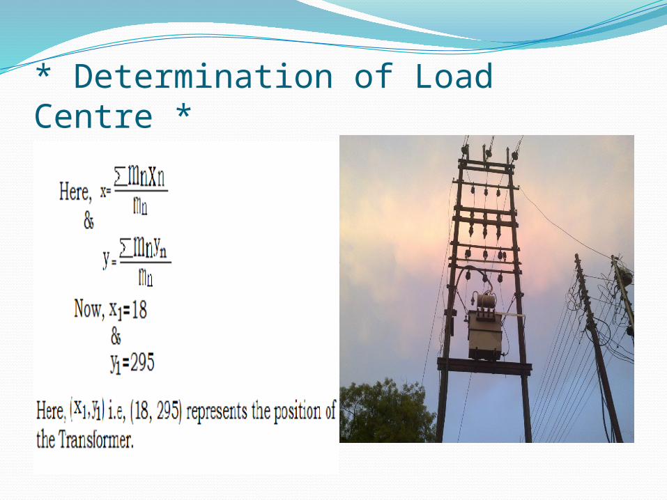
* Determination of Load Centre *

* Graphical Representation of ‘Load Centre’ *

* Calculation for Water Works *Assume, total Population= 450.Water used by each= 25 Gallons/Head/Day.So, Water necessary= 11,250 Gallons/ Day.Now, H.P.= = 17.08 HPHere, W= Specific Gravity= 62.4 Lb/ft. Q= Discharge in cubic ft./sec. H= Total head (In ft.)Taking Efficiency of the Pump= 70% & Demand
Factor= 1, we can calculate that Maximum Demand for Water Works= 18 kW

* Prediction of Future Loads * Forecasting the future load requirement is essential part of
power project design. This forecast of lone is done by two namely statically method and field survey method.
Fundamental law of statistical is that every phenomenon in future obeys some mathematical law which can be represented by a smooth curve load development in any area except due to unforeseen developments such as the establishment to this low. According to this method of annual maximum demand pertaining to the area is collected for past several years.
In the field survey method, existing requirement area is found out under different classes of load i.e. residential, commercial, industrial, municipal and agricultural. Future load requirement are then forecast taking into account various factors such as population growth , natural resources of the region standard of living of the people, topography and climate of the region.
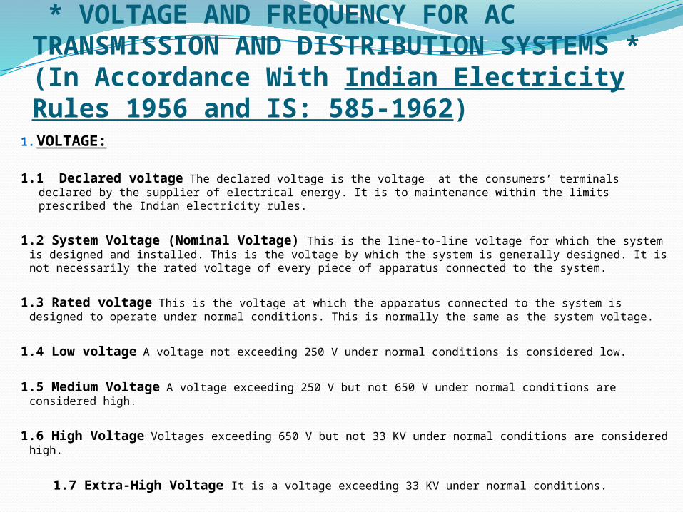
* VOLTAGE AND FREQUENCY FOR AC TRANSMISSION AND DISTRIBUTION SYSTEMS *(In Accordance With Indian Electricity Rules 1956 and IS: 585-1962)1. VOLTAGE:
1.1 Declared voltage The declared voltage is the voltage at the consumers’ terminals declared by the supplier of electrical energy. It is to maintenance within the limits prescribed the Indian electricity rules.
1.2 System Voltage (Nominal Voltage) This is the line-to-line voltage for which the system is designed and installed. This is the voltage by which the system is generally designed. It is not necessarily the rated voltage of every piece of apparatus connected to the system.
1.3 Rated voltage This is the voltage at which the apparatus connected to the system is designed to operate under normal conditions. This is normally the same as the system voltage.
1.4 Low voltage A voltage not exceeding 250 V under normal conditions is considered low.
1.5 Medium Voltage A voltage exceeding 250 V but not 650 V under normal conditions are considered high.
1.6 High Voltage Voltages exceeding 650 V but not 33 KV under normal conditions are considered high.
1.7 Extra-High Voltage It is a voltage exceeding 33 KV under normal conditions.
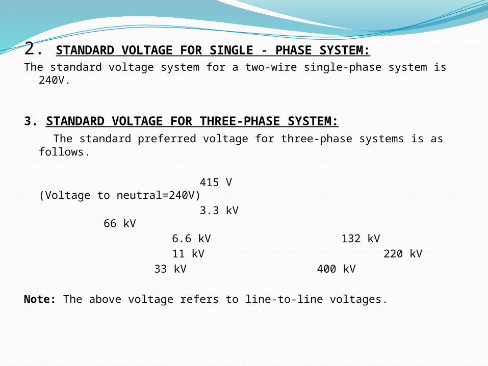
2. STANDARD VOLTAGE FOR SINGLE - PHASE SYSTEM:The standard voltage system for a two-wire single-phase system is 240V.
3. STANDARD VOLTAGE FOR THREE-PHASE SYSTEM: The standard preferred voltage for three-phase systems is as follows.
415 V (Voltage to neutral=240V) 3.3 kV 66 kV 6.6 kV 132 kV 11 kV 220 kV
33 kV 400 kV
Note: The above voltage refers to line-to-line voltages.

4. VOLTAGE LIMITS:
The voltage at the point of commencement of supply under conditions should not vary from the declared voltage by more than:
(i) 6% in case low or medium voltages. (ii) 6% on the higher side or by more than 9% on the lower side, in case
of high voltages. (iii)12.5% In case of extra-high voltages.
5. STANDARD SYSTEM FREQUENCY: The standard system frequency is 50 Hz. The frequency of an
alternating current supply should not very from the declared frequency by more than 3%.
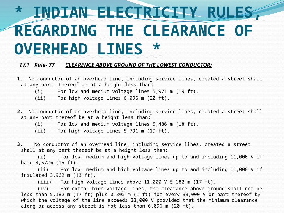
* INDIAN ELECTRICITY RULES, REGARDING THE CLEARANCE OF OVERHEAD LINES * IV.1 Rule- 77 CLEARENCE ABOVE GROUND OF THE LOWEST CONDUCTOR:
1. No conductor of an overhead line, including service lines, created a street shall at any part thereof be at a height less than:
(i) For low and medium voltage lines 5,971 m (19 ft). (ii) For high voltage lines 6,096 m (20 ft).
2. No conductor of an overhead line, including service lines, created a street shall at any part thereof be at a height less than:
(i) For low and medium voltage lines 5,486 m (18 ft). (ii) For high voltage lines 5,791 m (19 ft).
3. No conductor of an overhead line, including service lines, created a street shall at any part thereof be at a height less than:
(i) For low, medium and high voltage lines up to and including 11,000 V if bare 4,572m (15 ft).
(ii) For low, medium and high voltage lines up to and including 11,000 V if insulated 3,962 m (13 ft).
(iii) For high voltage lines above 11,000 V 5,182 m (17 ft). (iv) For extra –high voltage lines, the clearance above ground shall not be less than 5,182
m (17 ft) plus 0.305 m (1 ft) for every 33,000 V or part thereof by which the voltage of the line exceeds 33,000 V provided that the minimum clearance along or across any street is not less than 6.096 m (20 ft).
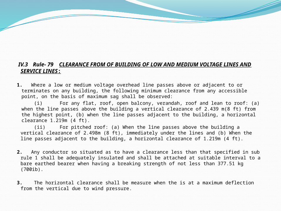
IV.3 Rule- 79 CLEARANCE FROM OF BUILDING OF LOW AND MEDIUM VOLTAGE LINES AND SERVICE LINES:
1. Where a low or medium voltage overhead line passes above or adjacent to or terminates on any building, the following minimum clearance from any accessible point, on the basis of maximum sag shall be observed:
(i) For any flat, roof, open balcony, verandah, roof and lean to roof: (a) when the line passes above the building a vertical clearance of 2.439 m(8 ft) from the highest point, (b) when the line passes adjacent to the building, a horizontal clearance 1.219m (4 ft).
(ii) For pitched roof: (a) When the line passes above the building a vertical clearance of 2.498m (8 ft), immediately under the lines and (b) When the line passes adjacent to the building, a horizontal clearance of 1.219m (4 ft).
2. Any conductor so situated as to have a clearance less than that specified in sub rule 1 shall be adequately insulated and shall be attached at suitable interval to a bare earthed bearer when having a breaking strength of not less than 377.51 kg (700ib).
3. The horizontal clearance shall be measure when the is at a maximum deflection from the vertical due to wind pressure.