Embed Size (px)
Citation preview
Modeling of Risers Using Hybrid FEA
Hugh Liu
Jan. 2015
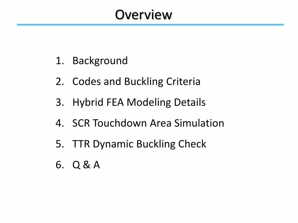
Overview
1. Background
2. Codes and Buckling Criteria
3. Hybrid FEA Modeling Details
4. SCR Touchdown Area Simulation
5. TTR Dynamic Buckling Check
6. Q & A

1. Background
• Automobile vs Offshore Oil Industry
• Compression, Buckling & FEA
• Beam & Shell Elements
3. Codes and Buckling Criteria
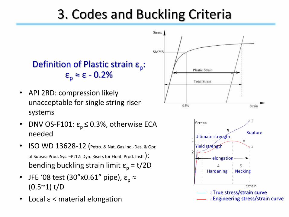
• API 2RD: compression likely unacceptable for single string riser systems
• DNV OS-F101: εp ≤ 0.3%, otherwise ECA needed
• ISO WD 13628-12 (Petro. & Nat. Gas Ind.-Des. & Opr.
of Subsea Prod. Sys. –Pt12: Dyn. Risers for Float. Prod. Instl.): bending buckling strain limit εp = t/2D
• JFE ‘08 test (30”x0.61” pipe), εp ≈ (0.5~1) t/D
• Local ε < material elongation
Definition of Plastic strain εp:εp ≈ ε - 0.2%
: True stress/strain curve: Engineering stress/strain curve
Ultimate strength
Yield strength
Rupture
Hardening Necking
elongation
4. Hybrid FEA Modeling Details
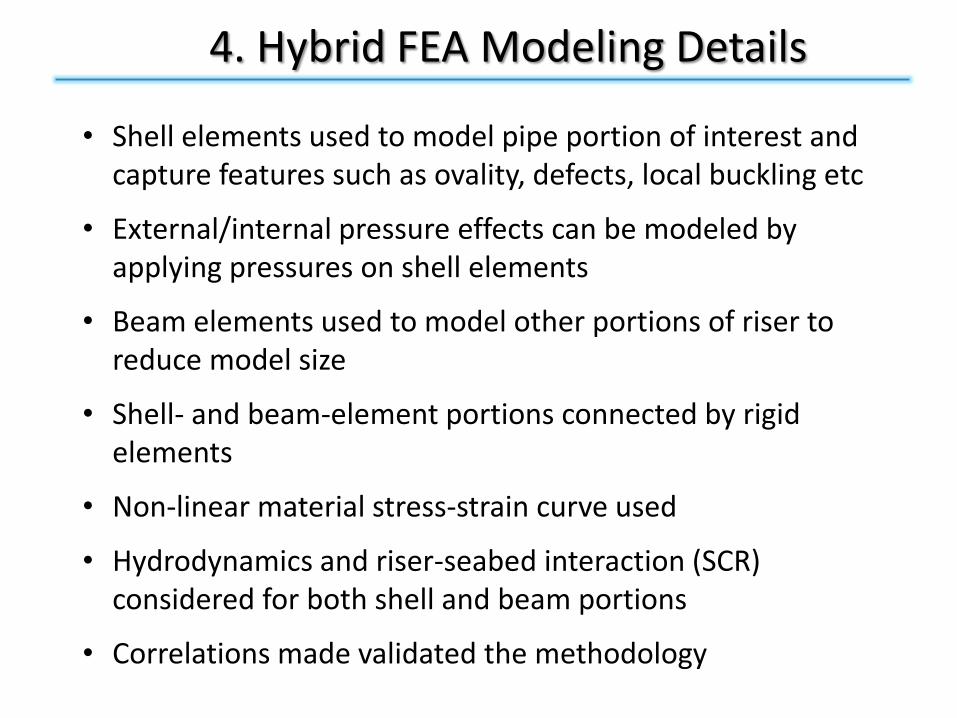
• Shell elements used to model pipe portion of interest and capture features such as ovality, defects, local buckling etc
• External/internal pressure effects can be modeled by applying pressures on shell elements
• Beam elements used to model other portions of riser to reduce model size
• Shell- and beam-element portions connected by rigid elements
• Non-linear material stress-strain curve used
• Hydrodynamics and riser-seabed interaction (SCR) considered for both shell and beam portions
• Correlations made validated the methodology
5. Touchdown Area Simulation for a SCR
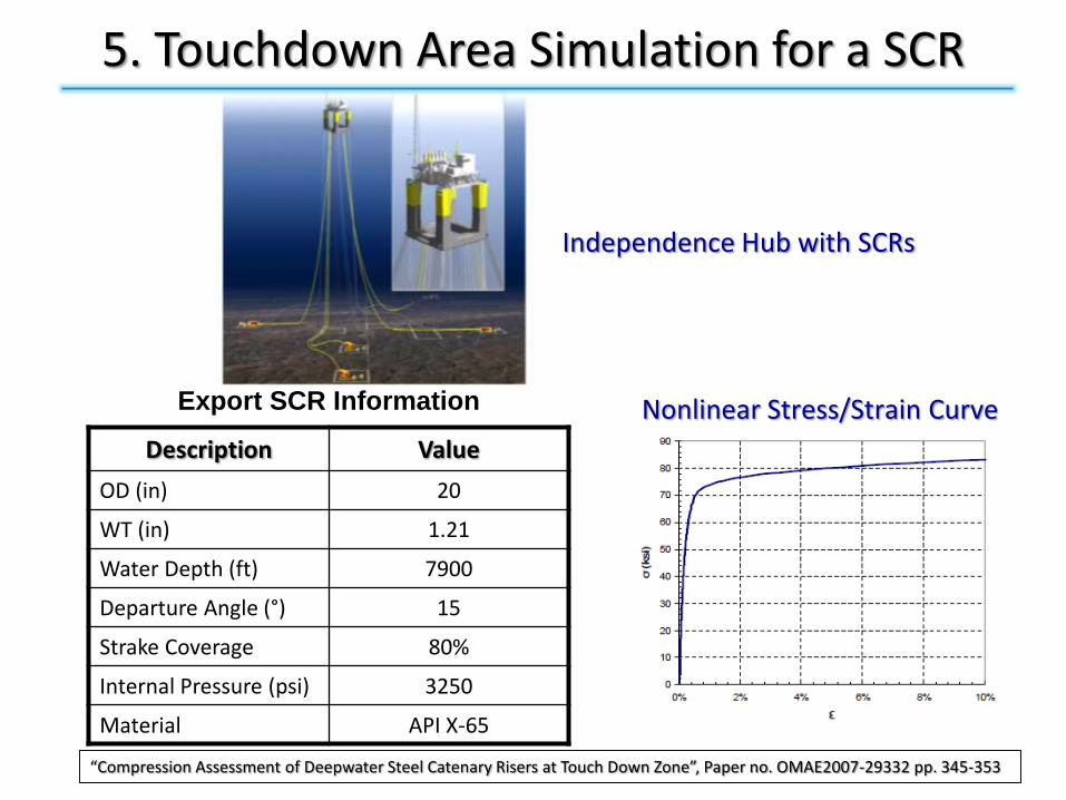
Export SCR Information
Description Value
OD (in) 20
WT (in) 1.21
Water Depth (ft) 7900
Departure Angle (°) 15
Strake Coverage 80%
Internal Pressure (psi) 3250
Material API X-65
Independence Hub with SCRs
Nonlinear Stress/Strain Curve
“Compression Assessment of Deepwater Steel Catenary Risers at Touch Down Zone”, Paper no. OMAE2007-29332 pp. 345-353
5. Touchdown Area Simulation for a SCR
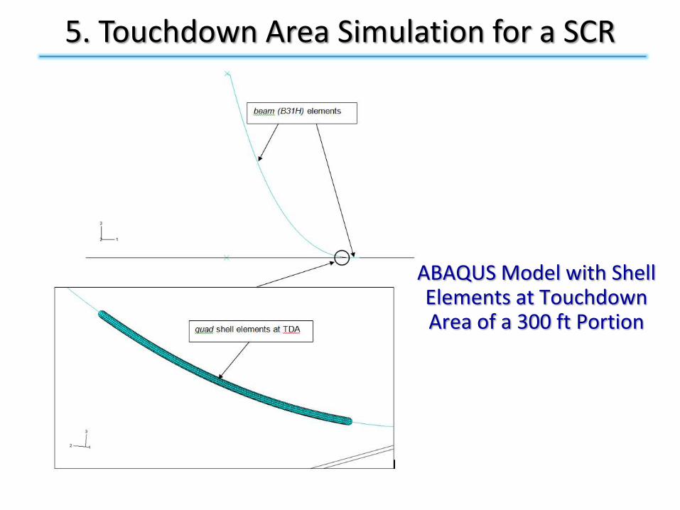
ABAQUS Model with Shell Elements at Touchdown Area of a 300 ft Portion
5. Touchdown Area Simulation for a SCR
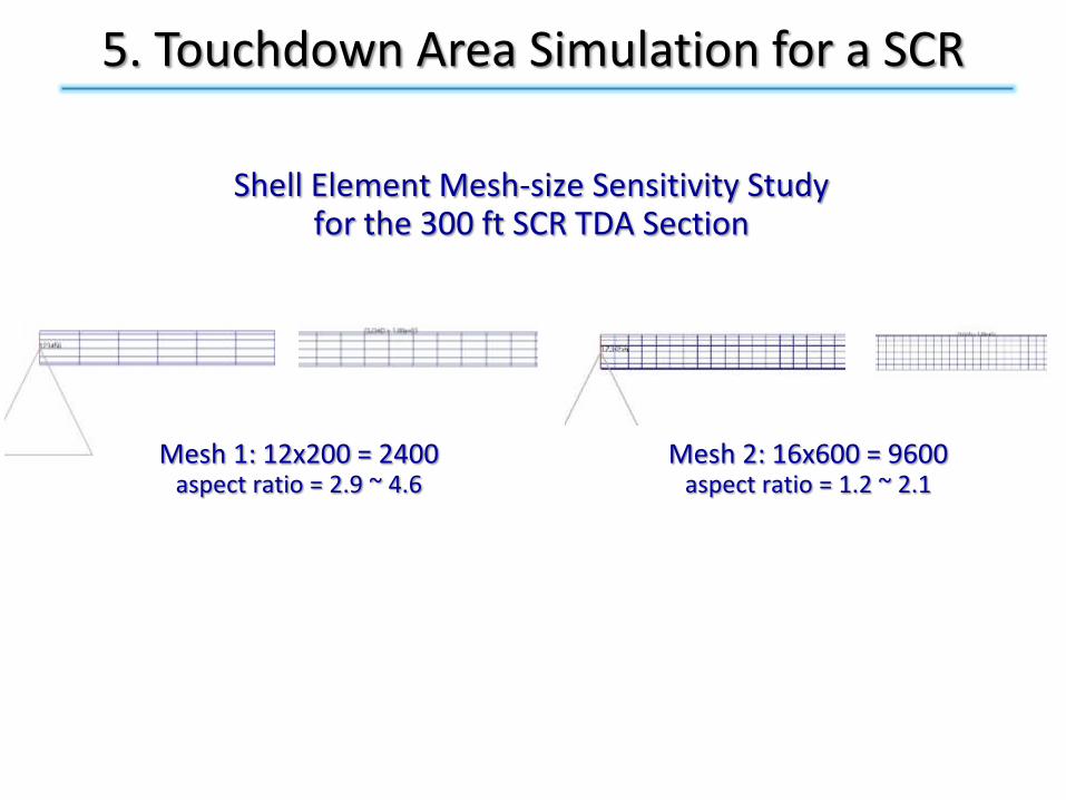
Shell Element Mesh-size Sensitivity Study for the 300 ft SCR TDA Section
Mesh 1: 12x200 = 2400aspect ratio = 2.9 ~ 4.6
Mesh 2: 16x600 = 9600aspect ratio = 1.2 ~ 2.1
5. Touchdown Area Simulation for a SCR
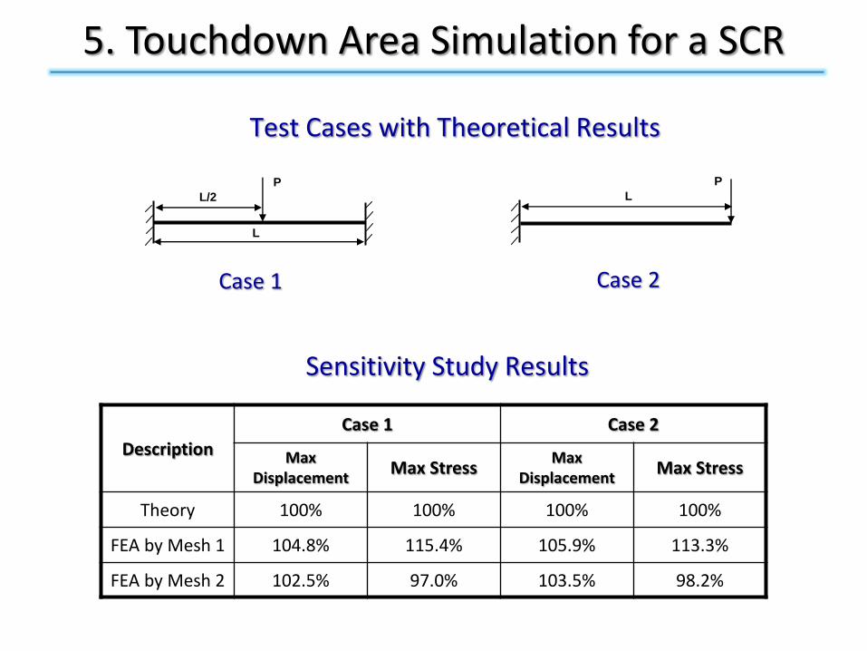
Sensitivity Study Results
Description
Case 1 Case 2
MaxDisplacement
Max StressMax
DisplacementMax Stress
Theory 100% 100% 100% 100%
FEA by Mesh 1 104.8% 115.4% 105.9% 113.3%
FEA by Mesh 2 102.5% 97.0% 103.5% 98.2%
P
L
L/2
Test Cases with Theoretical Results
P
L
Case 1 Case 2
-3.0E+05
-2.0E+05
-1.0E+05
0.0E+00
1.0E+05
2.0E+05
3.0E+05
4.0E+05
5.0E+05
6.0E+05
7.0E+05
8.0E+05
1250 1300 1350 1400 1450 1500 1550
Time (s)
SF
1 (
lb)
-10
-8
-6
-4
-2
0
2
4
6
8
10
Ve
rt V
el
(ft/
s)
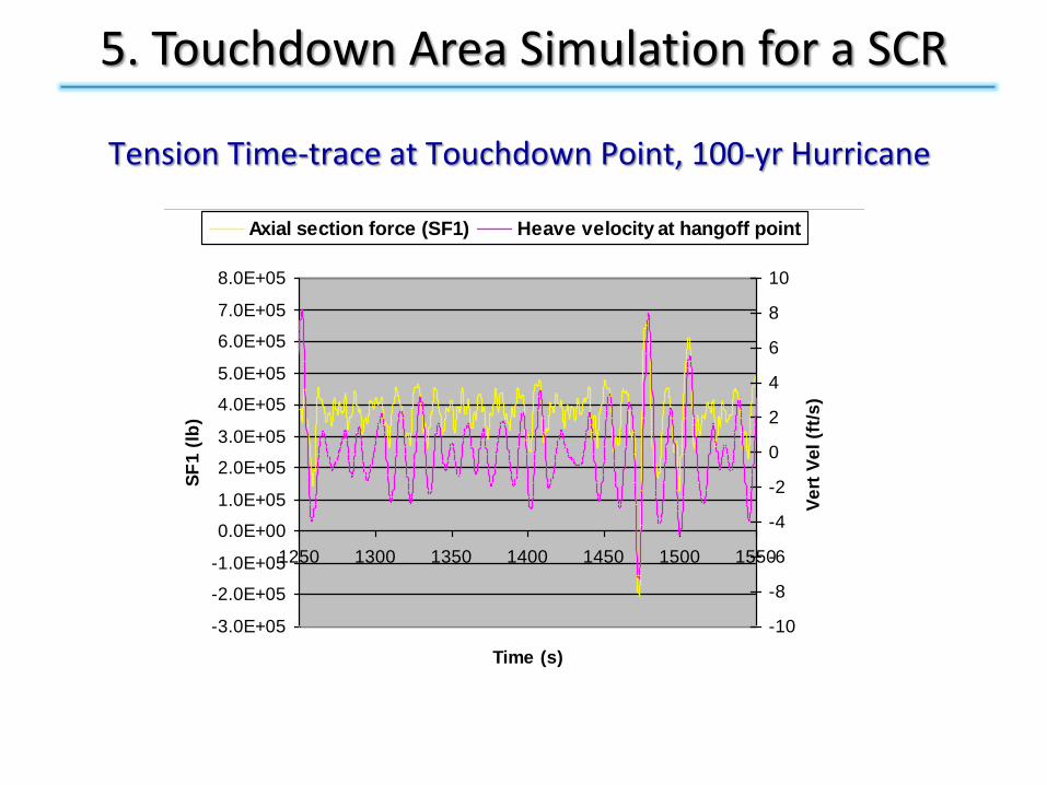
Axial section force (SF1) Heave velocity at hangoff point
5. Touchdown Area Simulation for a SCR
Tension Time-trace at Touchdown Point, 100-yr Hurricane
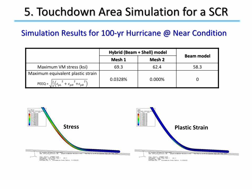
Simulation Results for 100-yr Hurricane @ Near Condition
Plastic StrainStress
5. Touchdown Area Simulation for a SCR
Hybrid (Beam + Shell) modelBeam model
Mesh 1 Mesh 2
Maximum VM stress (ksi) 69.3 62.4 58.3
Maximum equivalent plastic strain
PEEQ = 2
3𝜀𝑝𝐿
2+ 𝜀𝑝𝐻
2+𝜀𝑝𝑅
2 0.0328% 0.000% 0
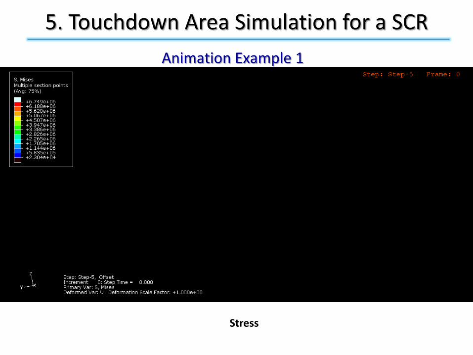
5. Touchdown Area Simulation for a SCR
Animation Example 1
Stress

5. Touchdown Area Simulation for a SCR
Animation Example 2
Plastic Strain
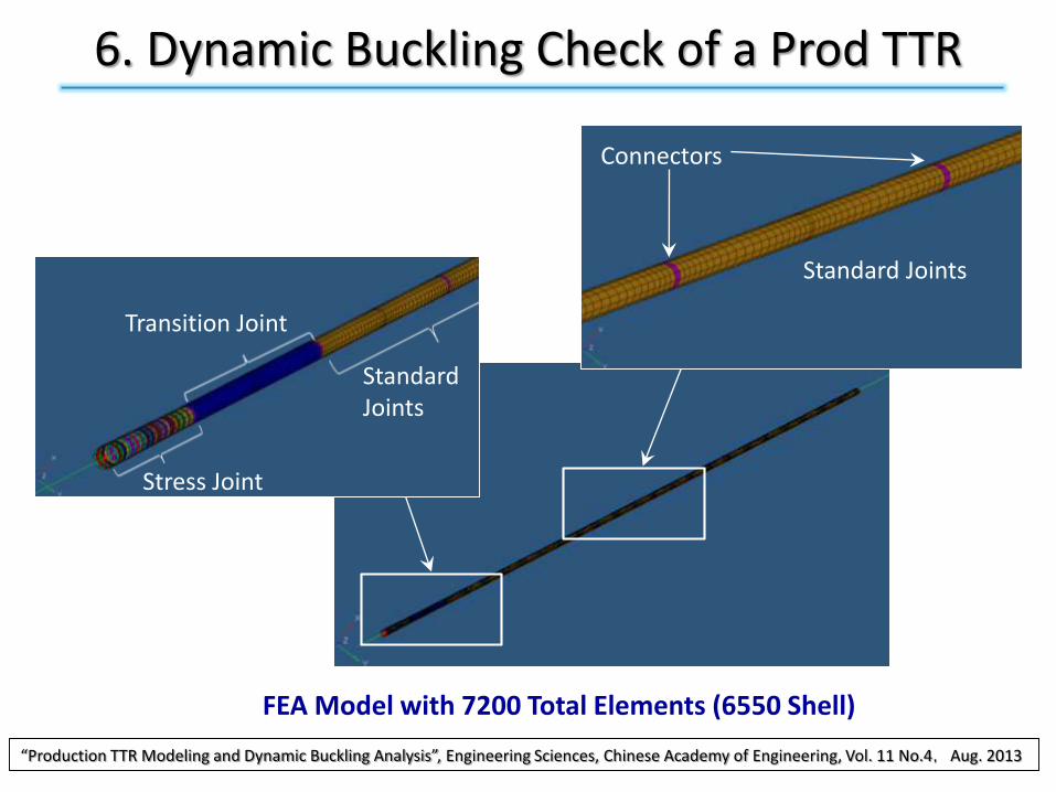
Stress Joint
Transition Joint
Standard Joints
Standard Joints
Connectors
FEA Model with 7200 Total Elements (6550 Shell)
6. Dynamic Buckling Check of a Prod TTR
“Production TTR Modeling and Dynamic Buckling Analysis”, Engineering Sciences, Chinese Academy of Engineering, Vol. 11 No.4,Aug. 2013
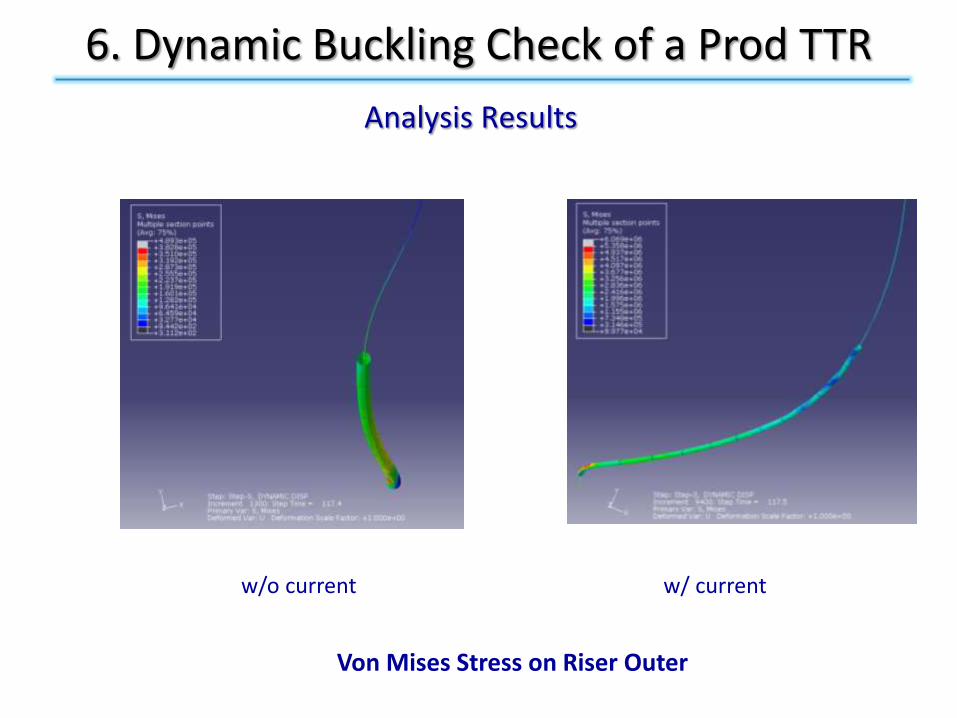
w/o current w/ current
Von Mises Stress on Riser Outer
6. Dynamic Buckling Check of a Prod TTR
Analysis Results
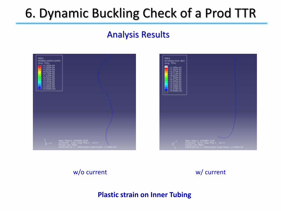
w/o current w/ current
Plastic strain on Inner Tubing
6. Dynamic Buckling Check of a Prod TTR
Analysis Results

w/o current w/ current
Tension Variation on Tensioner Cylinders
(One Tensioner Cylinder Damaged)
6. Dynamic Buckling Check of a Prod TTR
Analysis Results
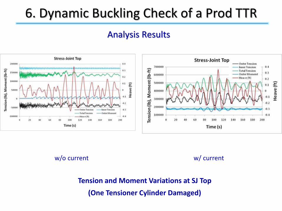
w/o current w/ current
Tension and Moment Variations at SJ Top
(One Tensioner Cylinder Damaged)
6. Dynamic Buckling Check of a Prod TTR
Analysis Results

w/o current w/ current
Centralizer Force Variations
(One Tensioner Cylinder Damaged, Centralizer Position: 1,2-top, 3,4-btm)
6. Dynamic Buckling Check of a Prod TTR
Analysis Results
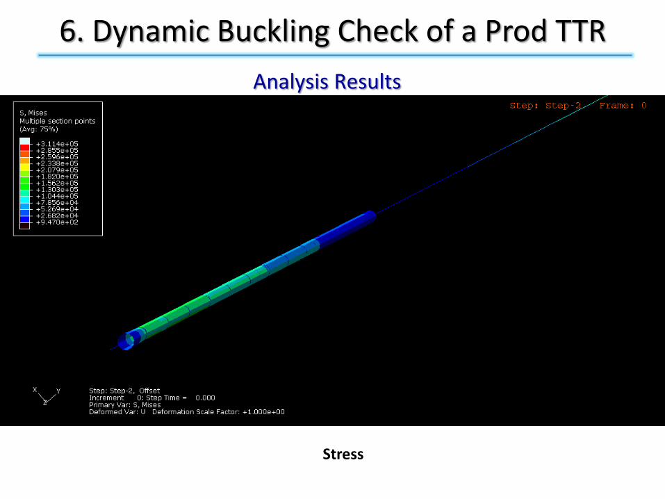
6. Dynamic Buckling Check of a Prod TTR
Analysis Results
Stress
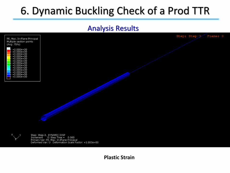
6. Dynamic Buckling Check of a Prod TTR
Analysis Results
Plastic Strain

7. Q & A