Embed Size (px)
Citation preview
Submitted to:- Presentation by:-Deptt. Of petroleum engg. Himanshu Rajawat UCE, RTU Kota Final year
Measurement While Drilling

1. Introduction 2. Objective Of MWD 3. Telemetry Principle 4. Survey Sensors 5. Application of MWD
Including…….
MWD is the process by which certain information is measured near the bit and transmitted to surface without interrupting normal drilling operations. The type of information may be :(a) directional data (inclination, azimuth, toolface);(b) formation characteristics (gamma-ray, resistivity logs);(c) drilling parameter (downhole WOB, torque, rpm);
Introduction
- Measurement the direction & inclination of the wellbore- Allow drilling tools to be oriented (mud motors, whipstocks)- provide mechanism for transmitting downhole data to surface- may provide gamma ray & drilling mechanics measurements- may provide power for lwd tools
Objectives of MWD

Telemetry Principle Three types of telemetry systems are used:-1. Positive Pulse System2. Negative Pulse System3. Continuous wave system
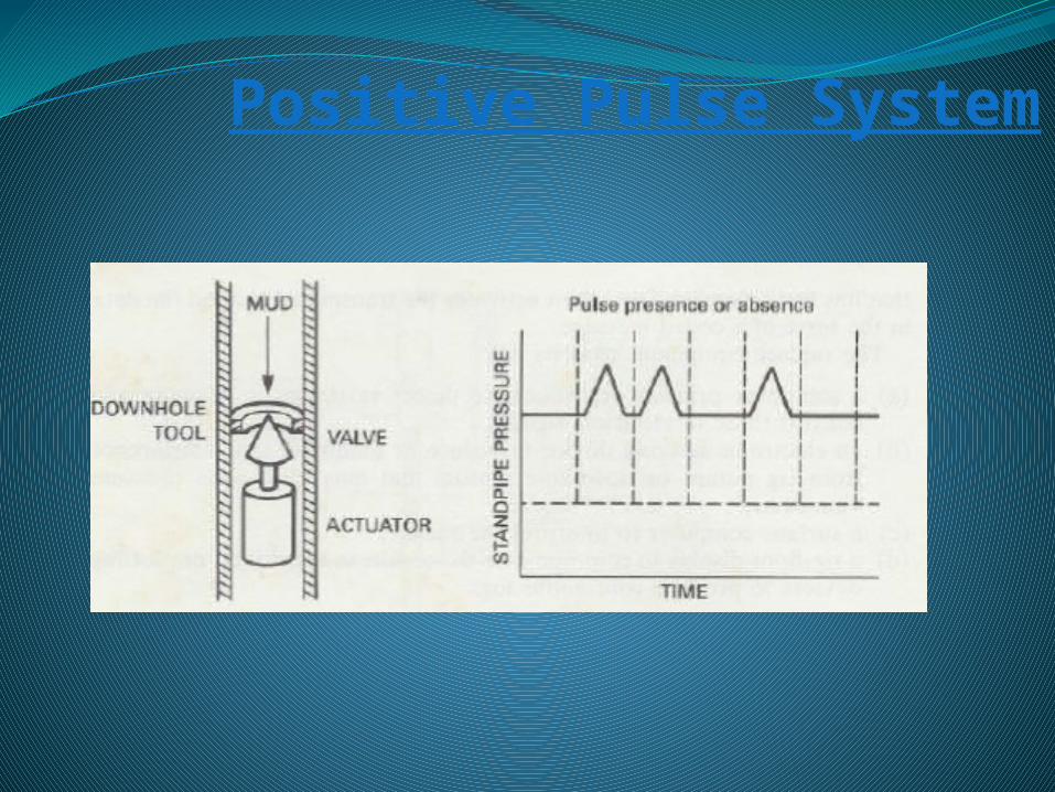
Positive Pulse System
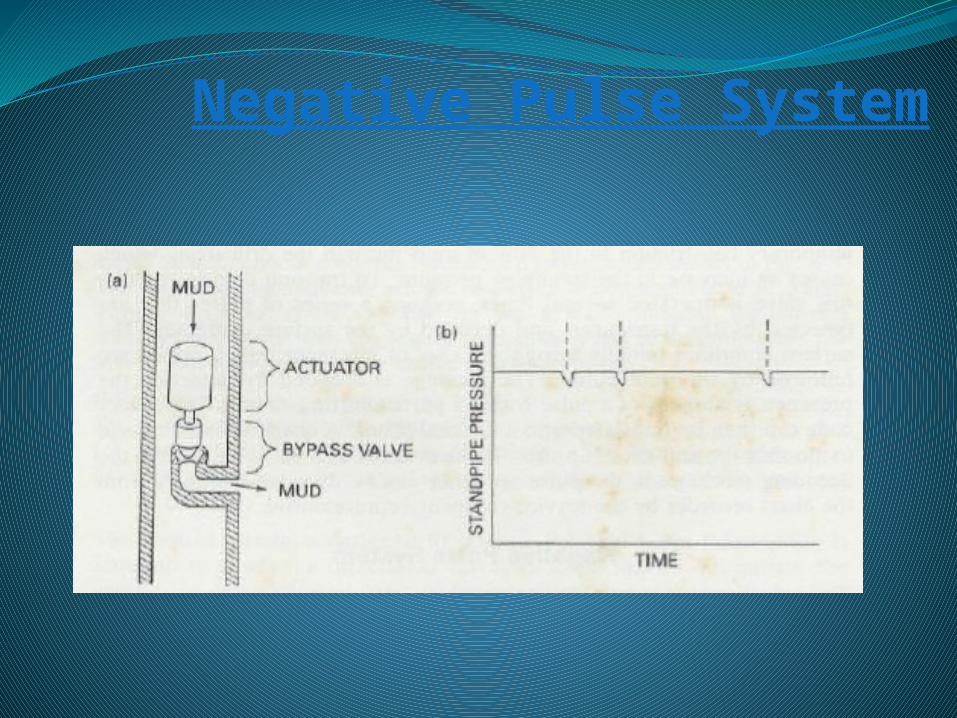
Negative Pulse System
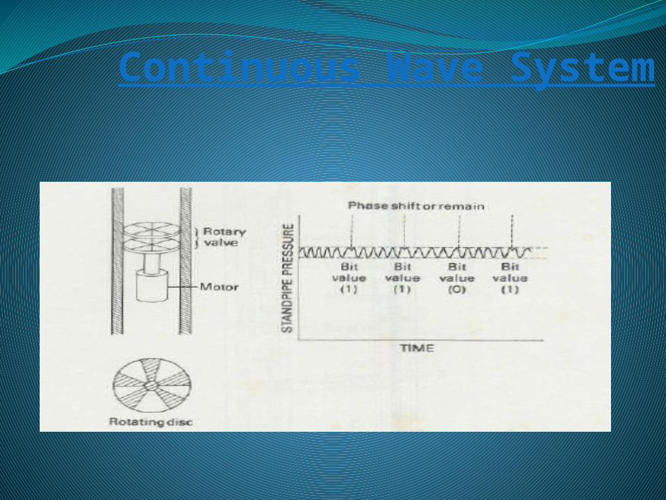
Continuous Wave System
Survey Sensors
1. Gamma-Ray Sensor2. Resistivity Sensor3. Temperature Sensor4. Downhole WOB/ Torque5. Turbine RPM6. Standpipe Pressure Transducer
Survey Sensors
1. Gamma-ray Sensor- Gamma-rays are emitted by radioactive elements such as isotopes of potassium, thorium and uranium. With this it is possible to identify shale zones 2. Resistivity Sensor:- Resistivity is a measure of the formation’s resistance to the flow of electric current. The response from the formation will depend on the fluid content. (Oil and gas act as insulator) 3. Temperature Sensor:- Monitors the annulus mud temperature. The sensing element may be a strip of platinum whose electrical resistance changes with temperature.
Survey Sensors
4. Downhole WOB/Torque:- Made by a system of sensitive strain gauges mounted on the bit. The strain gauges will detect axial forces for WOB and torsional forces for torque. 5. Turbine RPM:- consists of a 2-in. diameter probe that is placed very close to the top of the rotating turbine shaft. As the shaft rotates, an electric coil within the probe picks up voltage pulses due to the magnets. By counting the number of pulses over a certain interval, the turbine speed in rpm can be calculated.

Application of MWD
1. Directional Surveying2. Formation Evaluation3. Drilling Parameter

Thank You For Your Precious Time


![Welcome [] · 2019. 2. 16. · Speaker Bio Introduction –Noralis, Inc. –12 Years of Experience in Measurement While Drilling (MWD) • 3-years MWD Field Engineer (domestic + international)](https://img.dokumen.tips/doc/110x75/60f124f872b5ea2768418a17/welcome-2019-2-16-speaker-bio-introduction-anoralis-inc-a12-years.jpg)


![MWD, LWD and Downhole Drilling Systems - iFinder/iPZIG...2018/05/10 · LWD 1.37 ft [0.42] m Image gamma measurement Magnetic measurement 3½ Reg Box 2.37 ft 3½ Reg [0.72 m] 2.84](https://img.dokumen.tips/doc/110x75/61282c0fcff6a6156b0b2bf7/mwd-lwd-and-downhole-drilling-systems-ifinderipzig-20180510-lwd-137.jpg)


