Embed Size (px)
Citation preview
Abstract
The Training provided me a very Practical Environment to Explore and is the outcome of 60
Days of working with lots of enthusiasm and hard work.
A good framework of Engineering Departments and their Co-ordination is the backbone of any
organization of National Importance. HMT Machine Tools Ltd., Ajmer is indeed a prestigious
establishment of its kind and is a National Pride.
I worked at different departments of HMT Machine Tools Ltd., Ajmer for which I got
permission to work and learn at Manufacturing, Assembly, Foundry, Maintenance and Inspection
departments. I have prepared this report in partial fulfillment for the Award of the Degree of
Bachelor of Technology in Department of Mechanical Engineering. It should remain the
document of academic interest only and should not be used for other purpose unless permitted by
the respective organization.
1

Acknowledgement
In pursuing my Bachelor’s degree of Technology in Department of Mechanical Engineering
undertook the task of completing my Training Report on “Manufacturing Processes in HMT
Machine Tools Ltd., Ajmer.”
This report is a synergistic product of many minds.
I am grateful to many people for their insights and encouragement. I may not possibly mention
the names of all those people who have enriched and improved my knowledge. But without the
names of some people this Training Report would not be possible.
At the outset I would like to thank HMT Machine Tools Ltd., Ajmer, Mr. N.K. Gokhroo
(GM) for giving me the approval to pursue this Training in such a prestigious and professional
organization and also for their immense contribution towards execution and completion of the
Training.
I would like to express my profound gratitude to Mr. Alok Gaur (Manager- Training), my
guide to this project.
I would also like to thank Mr. Sudhan Verma (Sr. Supervisor- Foundry) and Mr. Sevaram
(Supervisor- Foundry) for their cooperation and support in the Training Tenure..
Finally, I take this opportunity to Thank Mr. Pawan Kalyane (Faculty guides) for showing faith
in me & giving me full freedom to work. He has been a great source of inspiration, guiding me
whenever I needed his help. Working on the Training has been interesting and rewarding due to
support and freedom he has given me.
Last but not the least, I thank all those who directly or indirectly contributed & helped me, while
working on the project.
Siddharth Bhatnagar
2
Practical Training: Overview
Practical training refers to students’ work experience in an engineering-practice environment to
familiarize themselves with professional engineering practices prior to graduation. The Rajasthan
Technical University prescribed 8 weeks continuous practical training for all undergraduate
engineering programs. All engineering students must complete at least 8 weeks of Practical
training as one of the requirements to be awarded a Bachelor of Technology. It is a mechanism to
integrate engineering practices in the curriculum to achieve the overall Program Outcomes and
Graduates Attributes. Student shall undergo the Practical training during the summer break after
VI Semester examinations.
Students should note that Practical training is an essential component in the engineering
curriculum. It provides exposure to engineering processes at a practical level; helps developing
professional skills required by an engineer and offers opportunity to prospective employment.
Many employers regard this period as a chance to assess potential employees for future
employment.
All engineering students should make considerable effort and give sufficient thought into
obtaining the most effective training for themselves. Whilst challenging, it is desirable to obtain
training that covers a range of activities, such as design, laboratory and on-site field works.
Objectives
The Practical Training helps us:
To apply engineering knowledge learned in classroom in real industrial/Laboratory
situations;
To get the knowledge of advanced tools and techniques
To expose to professional engineering practices in the industries;
To understand the role and responsibilities as well as code of ethics that engineers should
uphold;
To develop awareness about general workplace behaviors and build interpersonal and
team skills.
To prepare professional work records and reports; to build network with future employers
to increase employability.
3
Practical training Report
A practical training report needs to be prepared after completion of training. A copy of the report
should be submitted to the coordinator. The report is a compiled document that demonstrates my
learning and development in technical knowledge, engineering practices and professional skills
through the practical experience. The practical training report should also reflects the ability in
communicating engineering context such as design, processes, evaluation and decision making in
a clear and concise manner through technical reports.
I ensure the Company/ Organization that no confidential materials are included in the report.
Summary
The objective is to do the Practical Summer Training of Manufacturing Processes of the
company. The Time Interval of the Training is from May 21st to July 20, 2015.
The information used in it is mainly from personal talks with the AGM Mr. Alok Gaur and
Supervisor Mr. Sudhan Verma of the company who shared the info like raw material
processing, finished goods, processes and techniques involved etc. Besides this, Workers and
Operator Interaction, and Websites were also helpful in getting the data.
4
ContentsChapter- 1: Background/ Profile of Company.................................................................................7
1.1 HMT Machine Tools Limited, Ajmer....................................................................................7
1.2 Vision, Mission and Values.................................................................................................10
1.2.1 Vision............................................................................................................................10
1.2.2 Corporate Mission.........................................................................................................10
1.2.3 Values............................................................................................................................10
1.3 Organization Structure Of HMT Machine Tools Ltd., Ajmer.............................................12
Chapter- 2: Summary of Duties.....................................................................................................13
Chapter- 3: Working Experience...................................................................................................15
3.1 Different Departments and Process Description of HMT....................................................15
3.1.1 Human Resource Department.......................................................................................15
3.1.2 Foundry Department......................................................................................................15
3.1.3 Manufacturing and Assembly Department:..................................................................22
3.1.4 Material Testing Department:.......................................................................................28
3.1.5 Service & Inspection Department:................................................................................52
3.1.6 Materials Department:...................................................................................................52
3.1.7 Planning Department:....................................................................................................52
3.1.8 Design Department:.......................................................................................................53
3.1.9 Finance Department:.....................................................................................................53
3.1.10 Sales Department:........................................................................................................53
3.1.11 Security Department:...................................................................................................54
3.1.12 Quality Assurance Department:..................................................................................54
3.2 Products and Grinding Solutions by HMT Ajmer:..............................................................55
5
3.3 Major Achievement in Last Five Years (In House Development):.....................................67
Chapter- 4: Conclusion..................................................................................................................68
4.1 Major Work Performed:.......................................................................................................68
4.2 Five S – Workplace Management:.......................................................................................68
4.3 Recommendations:...............................................................................................................69
6
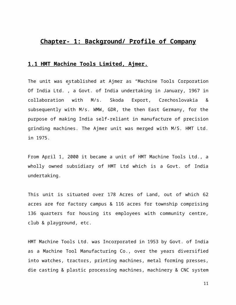
Chapter- 1: Background/ Profile of Company
1.1 HMT Machine Tools Limited, Ajmer.
The unit was established at Ajmer as “Machine Tools Corporation Of India Ltd.”, a Govt. of
India undertaking in January, 1967 in collaboration with M/s. Skoda Export, Czechoslovakia &
subsequently with M/s. WMW, GDR, the then East Germany, for the purpose of making India
self-reliant in manufacture of precision grinding machines. The Ajmer unit was merged with
M/S. HMT Ltd. in 1975.
From April 1, 2000 it became a unit of HMT Machine Tools Ltd., a wholly owned subsidiary of
HMT Ltd which is a Govt. of India undertaking.
This unit is situated over 178 Acres of Land, out of which 62 acres are for factory campus & 116
acres for township comprising 136 quarters for housing its employees with community centre,
club & playground, etc.
HMT Machine Tools Ltd. was Incorporated in 1953 by Govt. of India as a Machine Tool
Manufacturing Co., over the years diversified into watches, tractors, printing machines, metal
forming presses, die casting & plastic processing machines, machinery & CNC system &
bearings. Today, HMT comprises 6 subsidiaries under the ambit of a holding co., which also
manages the tractors business directly. Successful technology absorption in all product groups
through collaboration with world renowned manufacturers & further strengthen by continuous
in-house R & D.
Due to its Presences in the Market for a long time and also because of the valued customer
satisfaction HMT Machine Tools Ltd. Ajmer Unit has gathered a lots of accolade at various
levels viz. National and International.
7
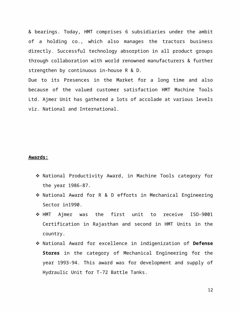
Awards:
National Productivity Award, in Machine Tools category for the year 1986-87.
National Award for R & D efforts in Mechanical Engineering Sector in1990.
HMT Ajmer was the first unit to receive ISO-9001 Certification in Rajasthan and second
in HMT Units in the country.
National Award for excellence in indigenization of Defense Stores in the category of
Mechanical Engineering for the year 1993-94. This award was for development and
supply of Hydraulic Unit for T-72 Battle Tanks.
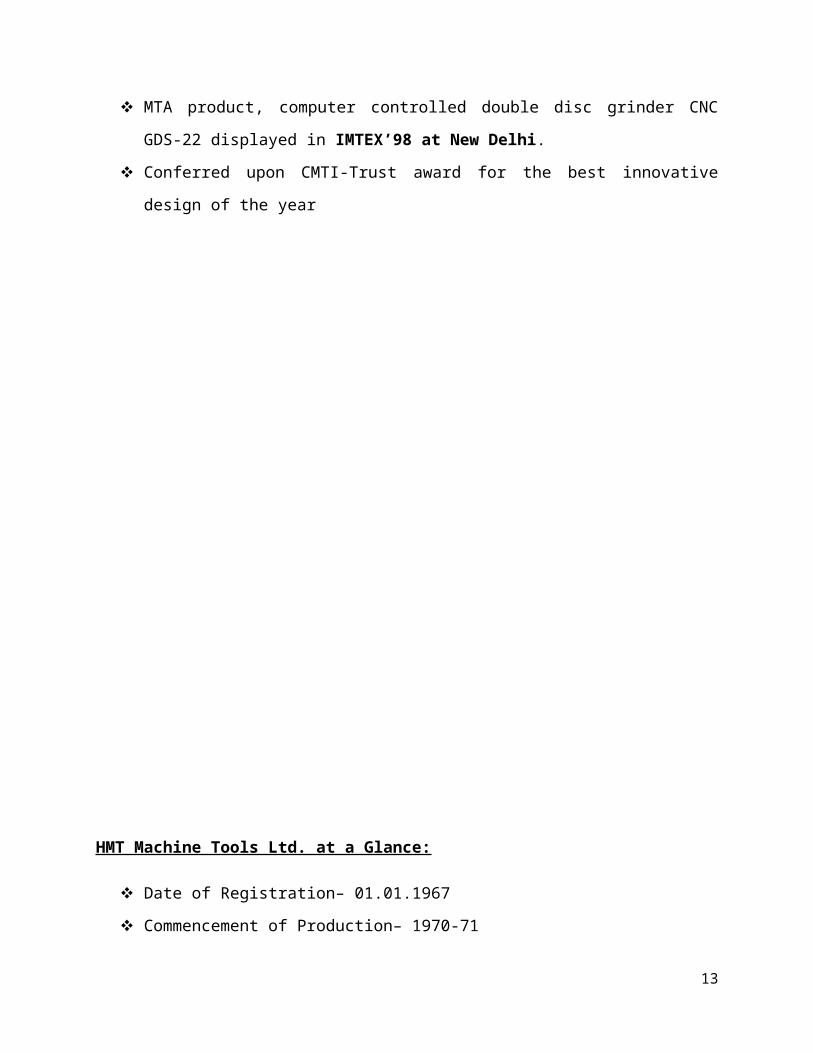
MTA product, computer controlled double disc grinder CNC GDS-22 displayed in
IMTEX’98 at New Delhi.
Conferred upon CMTI-Trust award for the best innovative design of the year
8
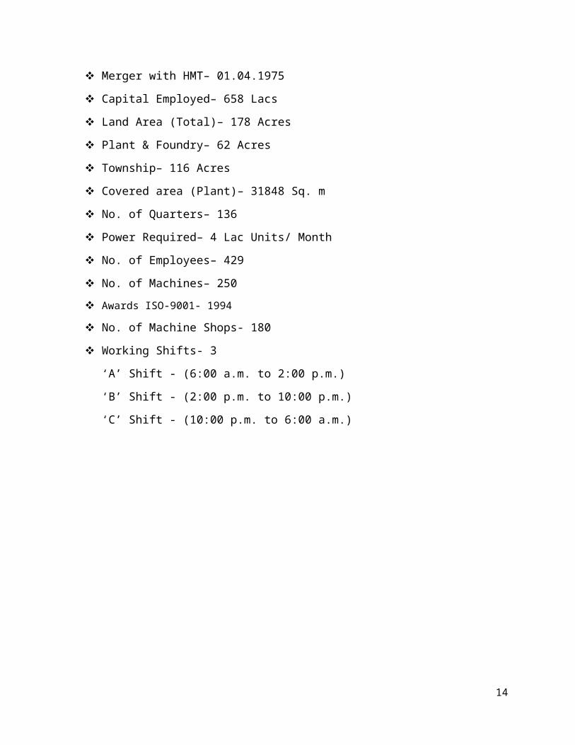
HMT Machine Tools Ltd. at a Glance:
Date of Registration– 01.01.1967
Commencement of Production– 1970-71
Merger with HMT– 01.04.1975
Capital Employed– 658 Lacs
Land Area (Total)– 178 Acres
Plant & Foundry– 62 Acres
Township– 116 Acres
Covered area (Plant)– 31848 Sq. m
No. of Quarters– 136
Power Required– 4 Lac Units/ Month
No. of Employees– 429
No. of Machines– 250
Awards ISO-9001- 1994
No. of Machine Shops- 180
Working Shifts- 3
‘A’ Shift - (6:00 a.m. to 2:00 p.m.)
‘B’ Shift - (2:00 p.m. to 10:00 p.m.)
‘C’ Shift - (10:00 p.m. to 6:00 a.m.)
9

1.2 Vision, Mission and Values
1.2.1 Vision
To be the world's largest and most admired CNC Grinder Manufacturing Company.
1.2.2 Corporate Mission
1. To establish ourselves as one of the world’s premiere companies in the engineering field
having strong international competitiveness.
2. To achieve market leadership in India through ensuring customer satisfaction by
supplying internationally competitive products & services at most affordable prices.
3. To achieve sustained growth in the earnings of the group on behalf of shareholders.
1.2.3 Values
Entrepreneurship
HMT foster an entrepreneurial spirit in our business and value the ability to foresee opportunities
early in the cycle and act on them swiftly. Whether it is developing growth projects or it is
debottlenecking the existing assets they ensure an entrepreneurial spirit at the heart of the
workplace.
Growth
They continue to deliver industry-leading growth and generate significant value for the
shareholders. Their growth is unique and are confident that they will continue to deliver
significant growth for shareholders in the future. They are not the only beneficiary of their
growth. They see growth as a means to enhance the wealth and prosperity of the society at large.
10
Excellence
Achieving excellence in all that they do is the way of life. They consistently deliver projects
ahead of schedule at industry-leading costs of construction and within budget. They are one of
the lowest cost CNC Grinder Manufacturers and their ongoing initiatives should help them to
further sharpen our cost performance. Equally important to them is achieving excellence in
health, safety and environment performance.
Trust
They value and cherish the trust reposed in them by their stakeholders. They recognize that they
must responsibly deliver on the promises they make to earn that trust. They constantly strive to
meet stakeholder expectations and deliver ahead of expectations. They always behave in a
manner that is consistent and upholds our value system. Their desire and ability to act in a
competent manner would help them to further build upon the trust of their stakeholders.
Sustainability
They pursue sustainability within the framework of well defined governance structures and
policies and with the demonstrated commitment of their management and employees. Their
sustainability team comprises over 200 full time resources including field workers. With the use
of appropriate technology and best in class practices, they always endeavor to minimize the
damage to the environment, and they do not miss any opportunity to leave a positive mark. Their
growth and business policy hinges around the philosophy of inclusive growth with a clear focus
on neighborhood communities.
11
1.3 Organization Structure Of HMT Machine Tools Ltd., Ajmer
The organization structure of H.M.T. Ltd. Ajmer is based on functions performed by various
people. General Technical Manager is on the top of the hierarchy, assisted by the Joint General
Manager. The Organization structure consists of following management levels in all:-
General Technical Manager
Joint General Manager
Deputy General Manager
Assistant General Manager
Manager
Deputy Manager
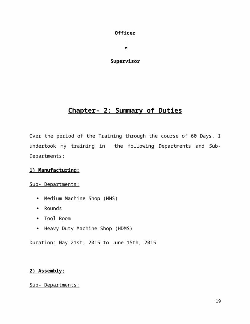
Officer
Supervisor
12
Chapter- 2: Summary of Duties
Over the period of the Training through the course of 60 Days, I undertook my training in the
following Departments and Sub- Departments:
1) Manufacturing:
Sub- Departments:
Medium Machine Shop (MMS)
Rounds
Tool Room
Heavy Duty Machine Shop (HDMS)
Duration: May 21st, 2015 to June 15th, 2015
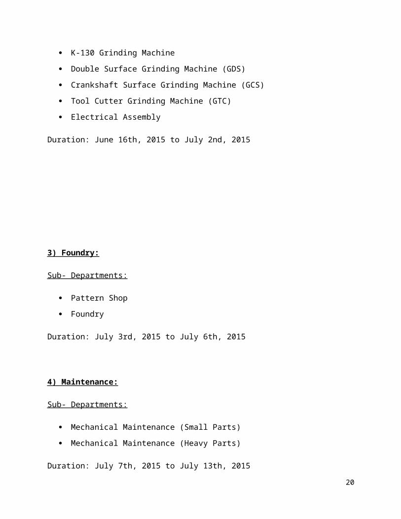
2) Assembly:
Sub- Departments:
K-130 Grinding Machine
Double Surface Grinding Machine (GDS)
Crankshaft Surface Grinding Machine (GCS)
Tool Cutter Grinding Machine (GTC)
Electrical Assembly
Duration: June 16th, 2015 to July 2nd, 2015
13
3) Foundry:
Sub- Departments:
Pattern Shop
Foundry
Duration: July 3rd, 2015 to July 6th, 2015
4) Maintenance:
Sub- Departments:
Mechanical Maintenance (Small Parts)
Mechanical Maintenance (Heavy Parts)
Duration: July 7th, 2015 to July 13th, 2015
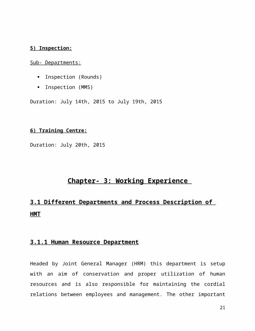
5) Inspection:
Sub- Departments:
Inspection (Rounds)
Inspection (MMS)
Duration: July 14th, 2015 to July 19th, 2015
6) Training Centre:
Duration: July 20th, 2015
14
Chapter- 3: Working Experience
3.1 Different Departments and Process Description of HMT
3.1.1 Human Resource Department
Headed by Joint General Manager (HRM) this department is setup with an aim of conservation
and proper utilization of human resources and is also responsible for maintaining the cordial
relations between employees and management. The other important functions of this department
are performance appraisal and different welfare activities for the employee.
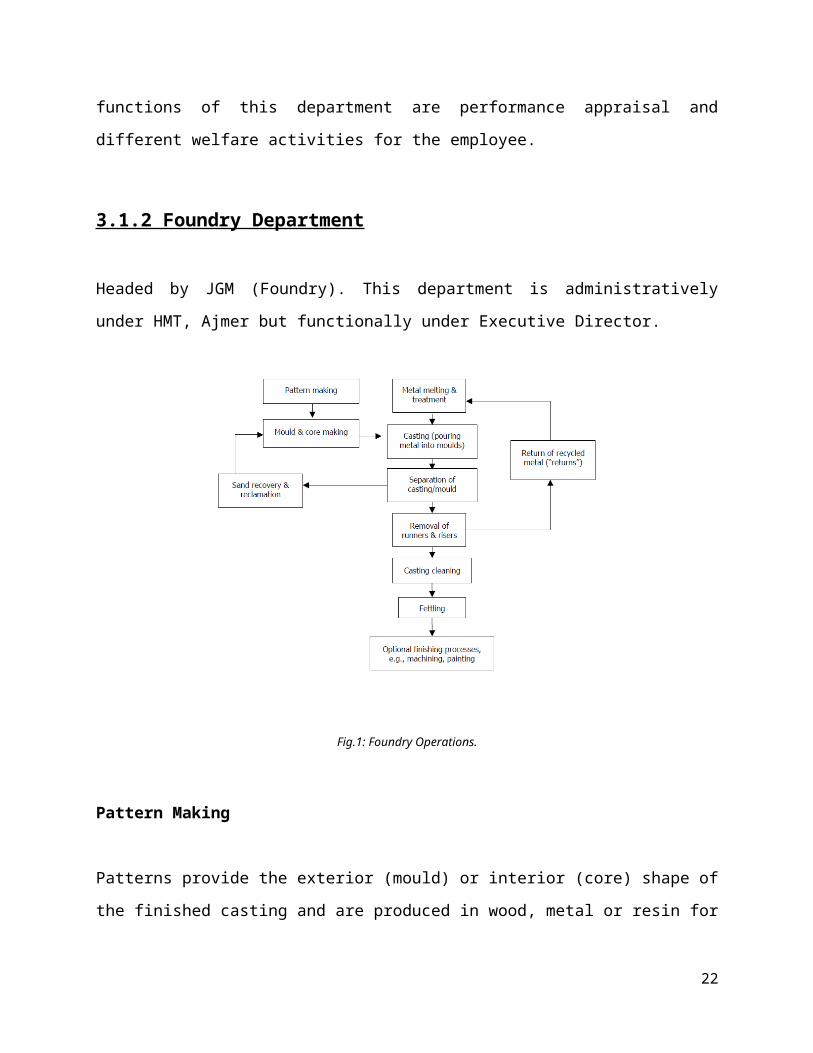
3.1.2 Foundry Department
Headed by JGM (Foundry). This department is administratively under HMT, Ajmer but
functionally under Executive Director.
Fig.1: Foundry Operations.
15
Pattern Making
Patterns provide the exterior (mould) or interior (core) shape of the finished casting and are
produced in wood, metal or resin for use in sand mould and core making. Patterns are usually
made in two halves.
A pattern may be defined as a replica or facsimile model of the desired casting which, when
packed or embedded in a suitable molding material, produces a cavity called mould. This cavity,
when filled with molten metal, produces the desired casting after solidification of the poured
metal. Since it is a direct duplication, the pattern very closely conforms to the shape and size of
the desired casting, except for a few variations due to the necessary allowances.
The most commonly used pattern materials in the industry are:
1) Wood. (e.g. Teak, Deodar etc.)
2) Metal. (e.g. Aluminum, Cast Iron, Bronze etc.)
3) Thermo-col.
4) Rubber.
5) Epoxy Resin.
Wood:
Wood are used for pattern making are of either teak or deodar or both of them. When both of
them are used, then teak is generally used on the inner sides because teak is harder and retains its
shape for longer times as compared to deodar which secretes a resign that on solidification can
affect the shape of the pattern which when used gives defective casting.
16
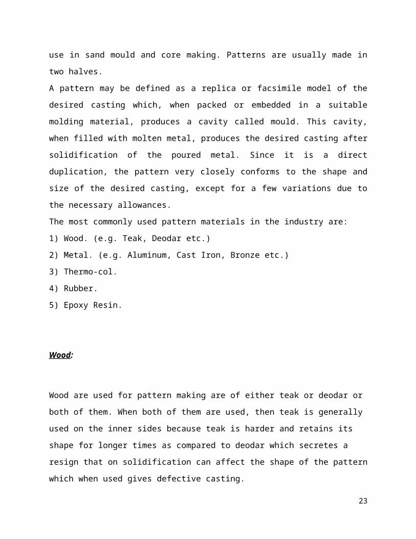
Comparison of Teak and Deodar:
1. Teak is easier to work in milling operation.
2. Teak is harder in comparison with deodar.
3. Teak has longer life so it is used in making patterns of those tools which are to be
manufactured in large numbers.
Fig.2: Molding with a Mesh Plate Pattern.
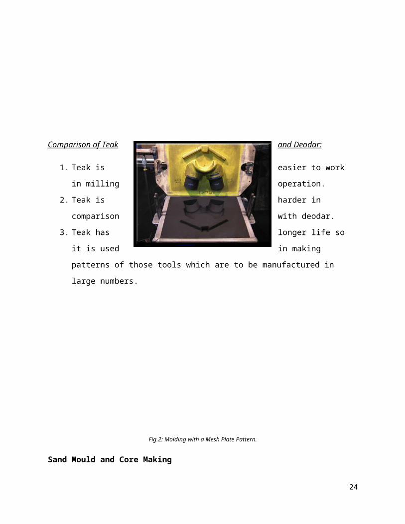
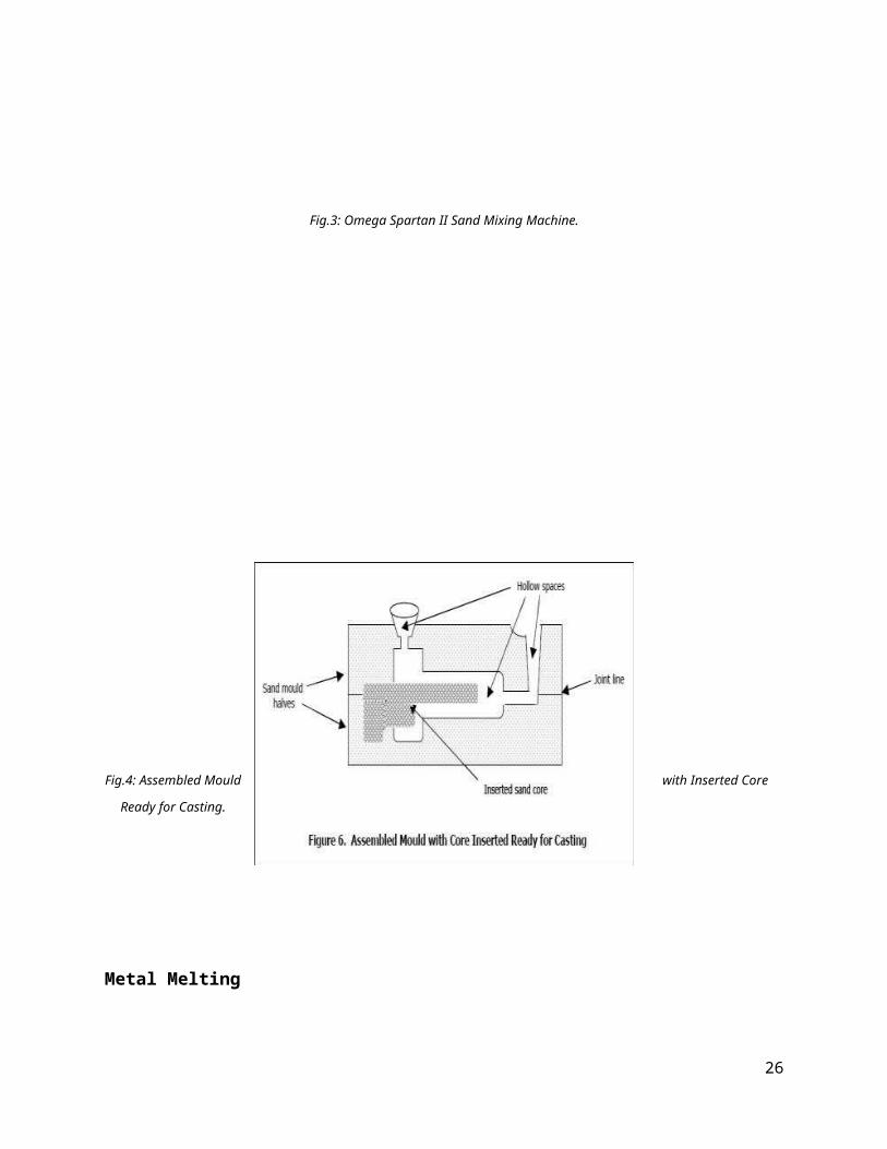
Sand Mould and Core Making
Sand casting is the most common production technique, especially for ferrous castings. Sand is
mixed with clay and water or with chemical binders and then packed or rammed around the
pattern to form a mould half. The two halves are joined together to make the mould - a rigid
cavity that provides the required shape for the casting, as shown in Fig. 6 below.
Variations on this technique include the use of plaster in place of sand and the recently invented
Pattern- less process (CDC 2000), where the mould is machined directly out of a sand block
without the need for a pattern. Cores are produced by blowing, ramming or in heated processes,
investing sand into a core box. The finished cores, which can be solid or hollow, are inserted into
the mould to provide the internal cavities of the casting before the mould halves are joined. Sand
cores are also widely used in Die- Casting, where permanent metal moulds are employed.
17
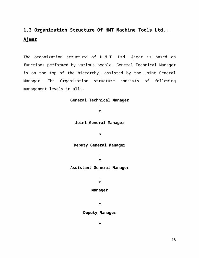
Fig.3: Omega Spartan II Sand Mixing Machine.
Fig.4: Assembled Mould with Inserted Core Ready for Casting.
18
Metal Melting
Molten metal is prepared in a variety of furnaces, the choice of which is determined by
the quality, quantity and throughput required.
Electric Induction Furnaces are the most common type used for batch melting of ferrous,
copper and super alloys. This method involves the use of an electrical current surrounding a
crucible that holds the metal charge. Furnace sizes range from < 100 kg up to 15 Tonnes.
For production of Super Alloys and Titanium, melting may be undertaken in a vacuum chamber
to prevent oxidation.
Specifications of 1.5 Tonne Capacity Furnace:
Line Voltage : 11000 Volts
Primary Voltage : 440 Volts
Power Voltage : 440 KW
Power Rating : 5 KA
Melting Power : 1 Tonne per Hour
Frequency : 50 Hz
Lining Thickness : 95 mm
Power Factor : 0.9
19
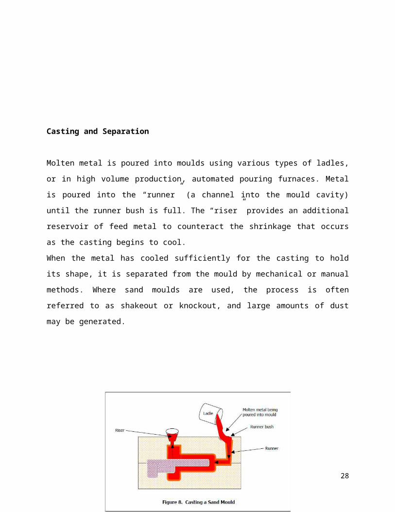
Casting and Separation
Molten metal is poured into moulds using various types of ladles, or in high volume production,
automated pouring furnaces. Metal is poured into the “runner” (a channel into the mould cavity)
until the runner bush is full. The “riser” provides an additional reservoir of feed metal to
counteract the shrinkage that occurs as the casting begins to cool.
When the metal has cooled sufficiently for the casting to hold its shape, it is separated from the
mould by mechanical or manual methods. Where sand moulds are used, the process is often
referred to as shakeout or knockout, and large amounts of dust may be generated.
Fig.5: Casting of a Sand Mould.
20
Removal of Runners and Risers
After casting, these extraneous pieces of metal are removed and often collected for re-melting. In
ferrous castings and larger non-ferrous castings, they may be removed by knocking off, sawing
or cutting using an arc air or oxy-propane torch. In die-castings, they are often snapped off
manually.
Finishing
A range of finishing processes is usually undertaken. These include:
♦ Cleaning to remove Residual Sand, Oxides and Surface Scale, often by shot or tumble blasting;
♦ Heat Treatment, including Annealing, Tempering, Normalizing and Quenching (in water or
oil) to enhance Mechanical Properties;
♦ Removal of excess metal or surface blemishes, (e.g., flash resulting from incomplete mould
closure or burrs left from riser cut-off), by Grinding, Sawing or Arc Air (oxy-propane cutting);
♦ Rectification of defects by Welding;
♦ Machining;
♦ Non Destructive Testing to check for defects;
♦ Priming, Painting or Application of a Rust Preventative Coating.
Sand Recovery and Reclamation
The industry recycles a large proportion of mould and core making sand internally for re-use.
This involves processing to remove tramp metal and returns the sand to a condition that enables
it to be used again for mould or core production.
21
3.1.3 Manufacturing and Assembly Department:
Headed by JGM (Manufacturing). HMT Ajmer’s manufacturing environment is highly
advanced; this department also looks after utilizing only the latest production techniques in all
phases of manufacturing maintenance. This assembly of machine is done stages, much as sub
assembly. Group assembly and final assembly of individual components. There subassemblies
after inspection pass on group assembly, which consists of head stock assembly, saddle, gearbox,
tail stock assemblies etc. this group then reaches to the final assembly to be fitted on the bed.
Electrical are also inter faced and the machine is ready for final testing and printing of plant and
equipment.
Small Parts and Heat Treatment:
This section of machine tool, HMT is primarily concerned with the manufacturer of small parts
of machine tools. The machines concerned are CNC machines, lathe machines, milling
machines, drilling machines etc. This department requires precision work.
Since there are number of small parts for number of machines and of different shapes, therefore
this department is further divided into different subsections. They are:
1 Spindle section
2 Turret section
3 Round section
4 Gearing section
5 Non round section
6 Sheet metals section
22
Spindle Section:
This section is concerned with the manufacturing of small cylindrical parts or spindles which
may be hollow, solid, shell type etc. according to machine’s requirement. The jobs concerned are
larger in size as compared to other sections. This section manufactures all the head related obs.
This machine requires for the purpose include lathe machines like LB26 lathe, centre lathe, turret
lathe. Also use of drilling machine is there .Thread cutting operation is also carried out in this
section. The job to be worked upon is supplied by the foundry department.
Examples of the parts manufactured: - Bearing Housing, Main Spindle, Shafts, Cam, Sleeves etc.
Turret Section:
This section is concerned with small job construction. These jobs requires precision works since
these parts are to be fitted in small areas and generally screwed up the machines involved in this
process are lathe machine and use of precision measuring instruments like Digital Micrometer,
Dial Vernier Caliper etc.
Examples of Parts Manufactured:- Nut, Bolts, Clamping Screw, Pins, Holder, Micro Nuts etc.
Round Section:
This section concerned with the round job construction and working. The section involves
operation like grinding, slotting, drilling etc.
Following are the lists of machines and operations concerned with them:-
Internal Grinding Machines:
Concerned with grinding of inner surface of job.
23
Surface Grinding Machines:
Concerned with outer surface of job. It uses magnetic chuck and shows only horizontal motion of
the table at the bed.
Rotary Grinding Machines:
Concerned with horizontal as well as rotational movement of the table. It also uses magnetic
chuck.
Cylindrical Grinding Machine:
This is used to grind cylindrical jobs with the motion of grinder itself. This job is held in the jaw
chuck.
Slotter:
This machine is concerned with slot cutting. It uses carbide tip and shows vertical motion of the
tool for slot cutting.
The other machines concerned with this section are Lathes, Drilling Machines etc.
24
Gearing Section:
Gear is used for power transmission of different parts of machines. This section is concerned
with teeth cutting. Proper indexing is maintained in the process with fixtures on the machines
concerned. There are four types of gears used in manufactured here:
1. Spur Gear
2. Worm Gear
3. Helical Gear
4. Bevel Gear
The various machines involved are:
Milling Machine:
Generally used for manufacturing of spur gears. Cutters of prescribed sizes are used.
Gear Hobbing Machines:
Gear hobbing machine is used for manufacture of worm gear. It uses hydraulic action.
Broaching Machine:
Broaching machine is used to put splines in gear.
Gear Teeth Grinding Machines:
It is used for grinding the teeth of the gears. In this machine gear teeth are grinded by a worm
type grinding wheel. Here the tooth profile are checked with a machine called Gear Tooth Profile
Tester.
25
Non- Round Section:
All the non-round jobs that are to be used in machines are machined here.
Components Manufacturing:
Blocks, Rectangular Strips, Gibs, Pump Body, Stop Block, Adjustable Plate, Clump Levers etc.
Operations Performed:
1. Marking
2. Vertical Milling
3. Drilling
4. Fitting
5. Grinding
Machines Used in Section:
Horizontal Milling Machine
Vertical Milling Machine
Surface Grinding Machine
26
Sheet Metal Section:
This section includes the cutting of sheets, bending of sheets at various angles. Various
operations like drilling, bending, shearing etc, are completed in this section. Some of the areas
where sheet metal are used are:
1. For outer body manufacture.
2. For making junction boxes in CNC machines.
Machines Used in Section:
Radial Arm Drilling Machine
Nibbling Machine
Bending Machine
Shearing Machine
NC Machine
27
3.1.4 Material Testing Department:
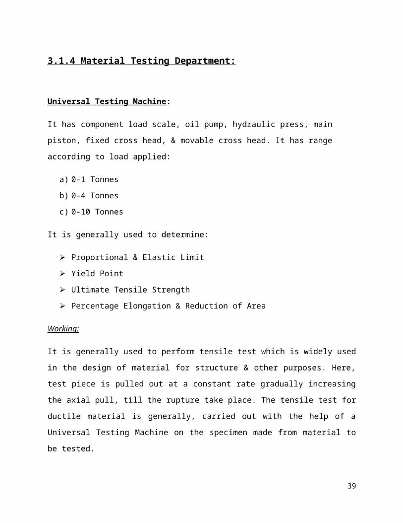
Universal Testing Machine:
It has component load scale, oil pump, hydraulic press, main piston, fixed cross head, & movable
cross head. It has range according to load applied:
a) 0-1 Tonnes
b) 0-4 Tonnes
c) 0-10 Tonnes
It is generally used to determine:
Proportional & Elastic Limit
Yield Point
Ultimate Tensile Strength
Percentage Elongation & Reduction of Area
Working:
It is generally used to perform tensile test which is widely used in the design of material for
structure & other purposes. Here, test piece is pulled out at a constant rate gradually increasing
the axial pull, till the rupture take place. The tensile test for ductile material is generally, carried
out with the help of a Universal Testing Machine on the specimen made from material to be
tested.
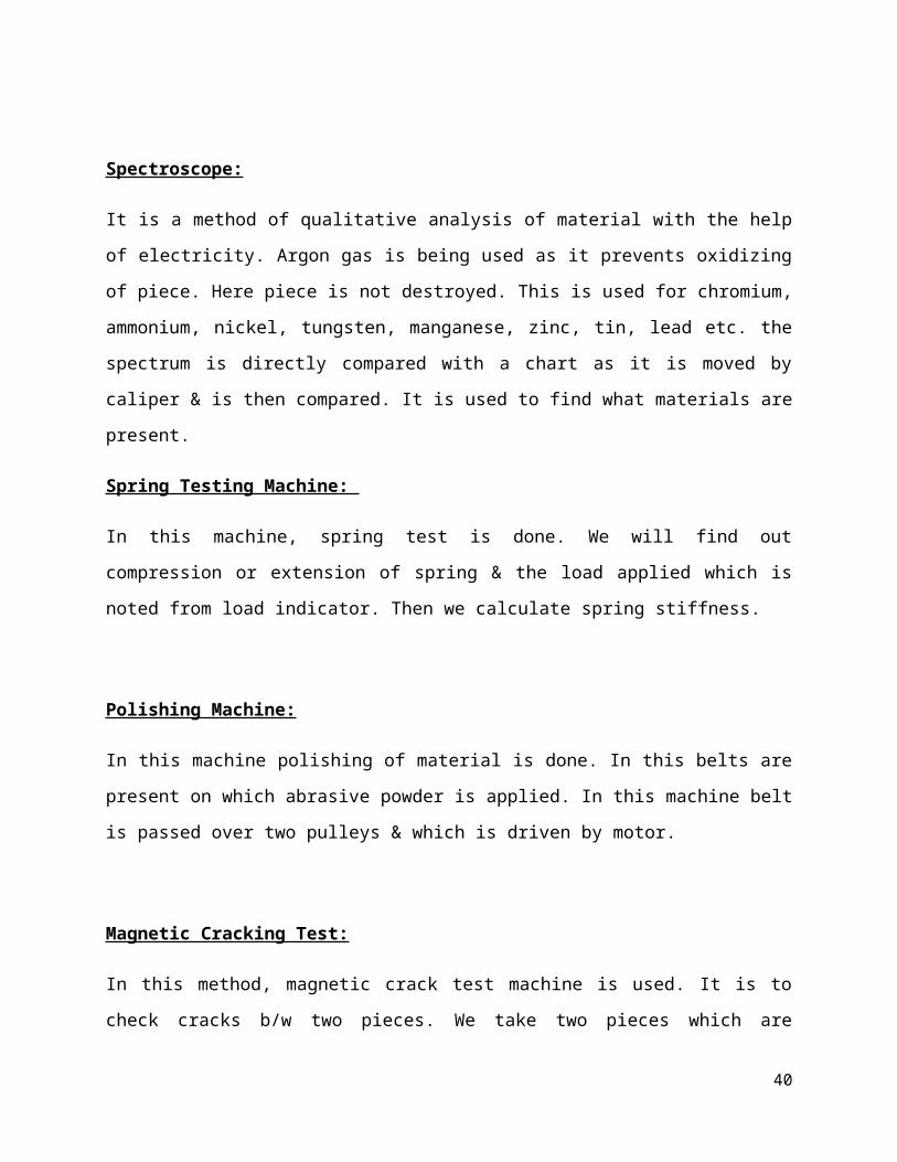
Spectroscope:
It is a method of qualitative analysis of material with the help of electricity. Argon gas is being
used as it prevents oxidizing of piece. Here piece is not destroyed. This is used for chromium,
ammonium, nickel, tungsten, manganese, zinc, tin, lead etc. the spectrum is directly compared
with a chart as it is moved by caliper & is then compared. It is used to find what materials are
present.
28
Spring Testing Machine:
In this machine, spring test is done. We will find out compression or extension of spring & the
load applied which is noted from load indicator. Then we calculate spring stiffness.
Polishing Machine:
In this machine polishing of material is done. In this belts are present on which abrasive powder
is applied. In this machine belt is passed over two pulleys & which is driven by motor.
Magnetic Cracking Test:
In this method, magnetic crack test machine is used. It is to check cracks b/w two pieces. We
take two pieces which are magnetized followed by spraying the iron chips. The ultra violet light
marked & fluorescent color is produced. Then Iron piece is glows due to ultra violet light.
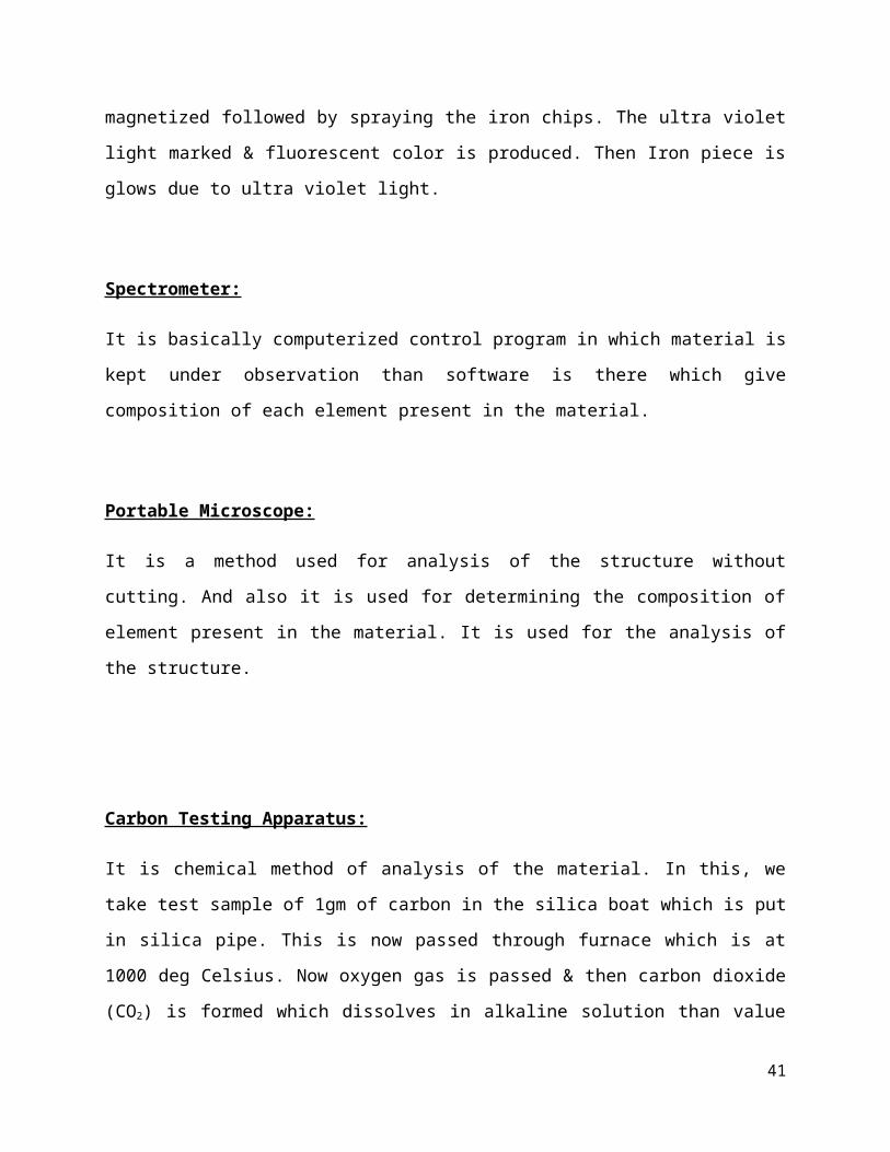
Spectrometer:
It is basically computerized control program in which material is kept under observation than
software is there which give composition of each element present in the material.
Portable Microscope:
It is a method used for analysis of the structure without cutting. And also it is used for
determining the composition of element present in the material. It is used for the analysis of the
structure.
29
Carbon Testing Apparatus:
It is chemical method of analysis of the material. In this, we take test sample of 1gm of carbon in
the silica boat which is put in silica pipe. This is now passed through furnace which is at 1000
deg Celsius. Now oxygen gas is passed & then carbon dioxide (CO2) is formed which dissolves
in alkaline solution than value is raised to corresponding exhaust temperature. Then carbon
content is determined as:
Carbon Content= 0.3 × Correction Factor × Volume Reading
Rockwell Hardness Test:
The Rockwell hardness test is generally performed when quick & direct reading is desirable.
This test is also performed when the material have hardness beyond the range of Brinell hardness
test. In this test the load for making indent are smaller & thus make smaller shallower indent. It
is because of this reason that the Rockwell hardness test is widely used in industry. This test has
nine scales of hardness (A to H & K). But B & C scales are widely used. The ball indenters are
generally made of hardened tool steel or tungsten carbide. During the test, the specimen is placed
on anvil, & raised till it comes in contact with indenter. A minor load of 100 KN is applied on
the specimen & the small pointer indicates set. Now the main pointer is also brought to the set
position. The major load is then applied & is allowed to continue for one second. The depth of
indentation in mm is read from the smaller pointer.
Vicker Hardness Test:
The Vicker Hardness Test is the most accurate test which has a fairly continuous scale of
hardness. The test makes the use of a diamond square based pyramid indenter. A piston & a
dashpot of oils used for controlling the rate & duration of the loading. The test is performed by
placing the specimen on an anvil & raised till it is close to the indenter point. The load is then
gradually applied to the indenter & then removed. This test is very suitable for testing polished &
hardened material or nitride surface due to small impression made on the test specimen.
30
Precautions:
The Indenter & Anvil should be Clean & Well placed.
The surface of the specimen should be Flat, Clean, Dry, & Smooth & should be placed
perpendicular to the Indenter.
31
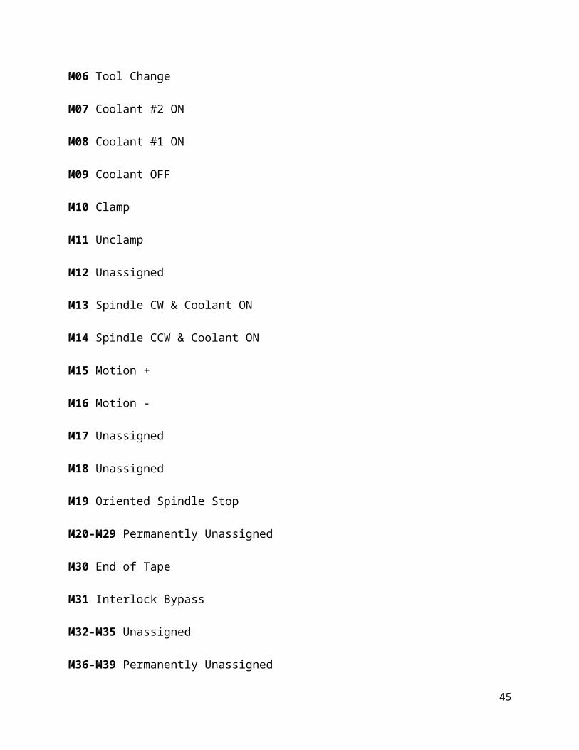
The different M- Codes and G- Codes used in a CNC Machine are as following:
M Codes:
M00 Program Stop
M01 Optional (Planned) Stop
M02 End of Program
M03 Spindle CW
M04 Spindle CCW
M05 Spindle OFF
M06 Tool Change
M07 Coolant #2 ON
M08 Coolant #1 ON
M09 Coolant OFF
M10 Clamp
M11 Unclamp
M12 Unassigned
M13 Spindle CW & Coolant ON
M14 Spindle CCW & Coolant ON
M15 Motion +
M16 Motion -
M17 Unassigned
32
M18 Unassigned
M19 Oriented Spindle Stop
M20-M29 Permanently Unassigned
M30 End of Tape
M31 Interlock Bypass
M32-M35 Unassigned
M36-M39 Permanently Unassigned
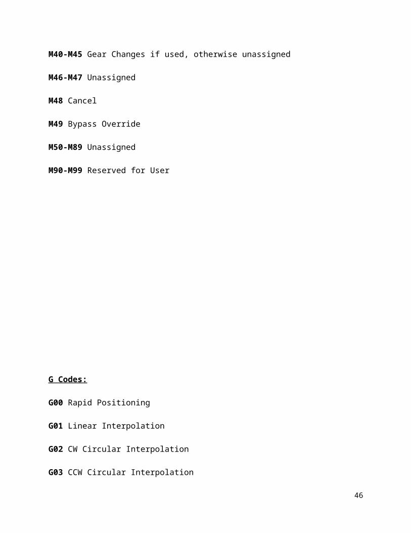
M40-M45 Gear Changes if used, otherwise unassigned
M46-M47 Unassigned
M48 Cancel
M49 Bypass Override
M50-M89 Unassigned
M90-M99 Reserved for User
33
G Codes:
G00 Rapid Positioning
G01 Linear Interpolation
G02 CW Circular Interpolation
G03 CCW Circular Interpolation
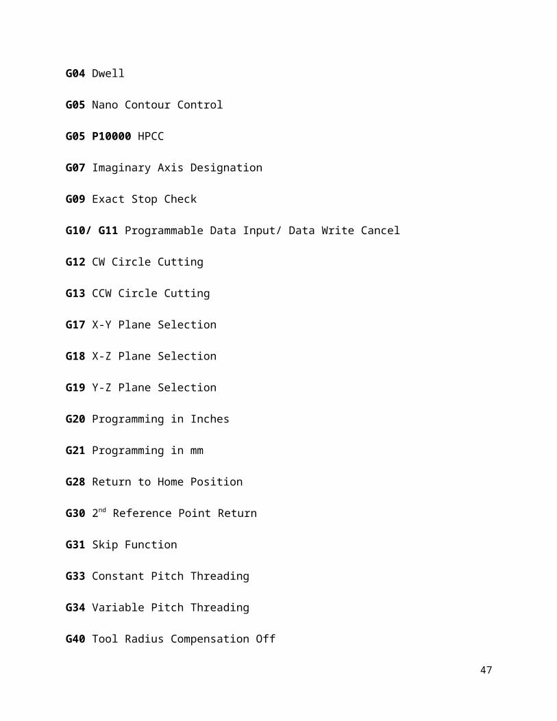
G04 Dwell
G05 Nano Contour Control
G05 P10000 HPCC
G07 Imaginary Axis Designation
G09 Exact Stop Check
G10/ G11 Programmable Data Input/ Data Write Cancel
G12 CW Circle Cutting
G13 CCW Circle Cutting
G17 X-Y Plane Selection
G18 X-Z Plane Selection
G19 Y-Z Plane Selection
G20 Programming in Inches
G21 Programming in mm
G28 Return to Home Position
G30 2nd Reference Point Return
G31 Skip Function
34
G33 Constant Pitch Threading
G34 Variable Pitch Threading
G40 Tool Radius Compensation Off
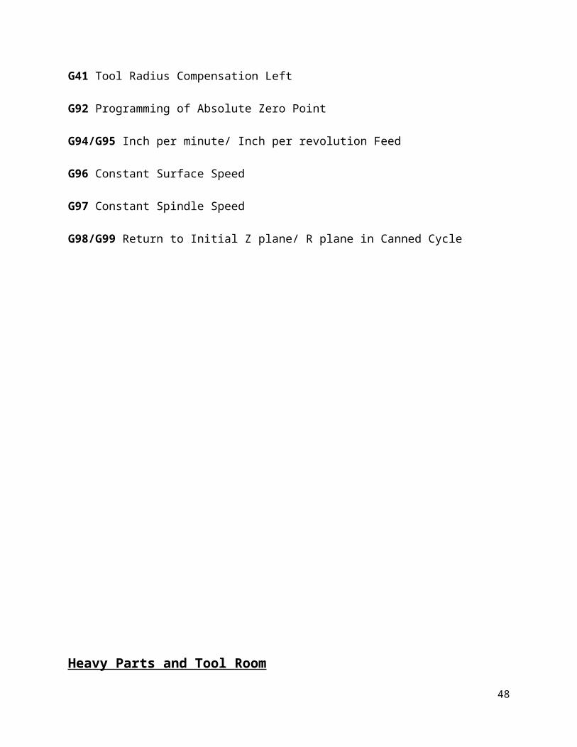
G41 Tool Radius Compensation Left
G92 Programming of Absolute Zero Point
G94/G95 Inch per minute/ Inch per revolution Feed
G96 Constant Surface Speed
G97 Constant Spindle Speed
G98/G99 Return to Initial Z plane/ R plane in Canned Cycle
35
Heavy Parts and Tool Room
Introduction:
It is the shop which gives the shape to the largest castings which come from the foundry after
being painted rough. In this section various operations are performed by the help of planers,
boring and planning-boring machines.
In this section, first of all the jobs are checked for the castings to be over-size or undersize. If
they are undersize, they are sent to scrap. If they are oversize, they are marked and sent for
machining.
Different types of operations are done by using different machines including various measuring
devices.
This section also includes in itself a high technology section in which advanced machines are
placed to machine crucial parts generally guide ways etc. It accommodates a tool preset device
which is used to set the tool of all machines and CNC machines. It is used to measure the length
and diameter of the tool with the help of leases.
This section is generally divided into two sections:
Planing
Boring
36
Planing:
This section consists essentially of planers mounted on one side of the section. In this section the
job planning is one of the basic operations done for machining process. It is primarily intended
for machining large flat surfaces.
Machines Installed:
Double Housing Planer
Open Side Planer
Plano Milling Machining
Horizontal Turning Centre
1) Double Housing Planer:
This is the heavy type of planer and is used for heavy cuts by double cutters. Its length is
3000mm. It consists of two columns, one on each side of bed. The cross rail is fitted
between the two housings which can accommodate one or two heads, according to the
specifications.
2) Open Side Planer:
This type of planer consists of a single column situated vertically on one side of the bed
and other side is left open without any column.
The cross-rail is wholly supported on the single column. Only one tool head can be
located on it as there is only one column.
37

3) Plano Milling Machine:
This is similar to a double housing planer but the tool can be milling tool. One of the
machines is TNC (three axis turning centre) in which only one axis can be moved at a
time. Thus round jobs cannot b machined here.
Another machine is CNC in which two axis can be moved simultaneously to machine
round job. The length of the bed is 2800mm.
Boring:
Boring is the operation of enlarging an already drilled hole. The holes are pre-drilled as in
casting only.
Machining time in Boring:
Machining time is the time required to complete the work place in a request period of time.
Time Required= Length of Cut / (RPM × Feed per meter)
Machines installed:
Horizontal Boring Machine
Vertical Boring Machine
Jig Boring Machine
38
Horizontal Boring Machine
In the horizontal boring machine, operations are performed on those large components which
cannot be rotated. The spindle and the boring bar are horizontal.
It has mechanical system and fixture is attached with table. The work table can be transverse
along and across the machine bed.
Vertical Boring Machine
The spindle is vertical and bores vertical holes in the spindle. The size of the machine is
determined by maximum length of the job which can be machined on it. The machine can also be
used as a drilling machine.
Jig Boring Machine
Jig boring machine is used to accurately enlarge existing holes and make their diameters highly
accurate. Jig boring can also maintain high accuracy between multiple holes and surfaces.
Tolerances can be held readily within ±0.002mm. The machine can also do accurate milling,
reaming, drilling and facing,
In general, the vertical jig boring machine employs a precision vertical tools spindle and
coordinate work table with a great accuracy. The position measuring system consists of accurate
lead screw with micrometer and an optical scale along with a Vernier.
The machine are of rail type i.e. they are constructed with a cross rail that is supported and
adjusted vertically on two columns. The cross rail serves to carry vertical spindle in its housing
along the transverse axis.
39
Tool Room:
This department keeps various kinds of tools which are useful during manufacturing of heavy
pats. Most of the tools are measuring devices such as Vernier Caliper, Micrometer etc.
Vernier Caliper:
A Vernier Caliper is a device used to measure the distance between two symmetrically opposing
sides.
The tips of the caliper are adjusted to fit across the points to be measured, the caliper is then
removed and the distance read by measuring between the tops with a measuring tool, such as a
ruler. Vernier calipers can measure internal dimensions (using the uppermost jaws in the
picture), external dimensions using the pictured lowered jaws and depending on the
manufacturer, depth measurements by the use of a probe that is attached to the movable head and
slides along the center of the body. This probe is slender and can get into deep grooves that may
prove difficult for other measuring tools.
The Vernier Scale may include both metric and inch measurements on the upper and lower part
of the scale.
Vernier Calipers commonly used in industry to provide a precision to a hundredth of a millimeter
(10 micrometers), or one thousandth of an inch.
Parts of Vernier Caliper
Outside Jaws: Used to measure External Diameter or width of an object
Inside Jaws: Used to measure Internal Diameter of an object
Depth Probe: Used to measure depth of an object or an hole
Main Scale: Gives measurements of up to one decimal place (in cm)
Main Scale: Gives measurements in fraction (in inch)
Vernier Gives measurements up to two decimal places (in cm)
Vernier Gives measurements in fraction (in inch)
Retainer: Used to block movable part to allow the easy transferring a measurement.
Micrometer:
40
A micrometer sometimes known as a “Micrometer Screw Gauge”, is a device used widely in
mechanical engineering and machining as well as most mechanical trades for precision
measurement, along with other metrological instruments such as Dial Calipers and Vernier
Calipers. Micrometers are often, but not always, in the form of Calipers.
Types of Micrometer:
Outside Micrometer (aka Micrometer Caliper): typically used to measure wires,
spheres, shafts and blocks.
Inside Micrometer: used to measure the diameter of holes.
Depth Micrometer: measures depths of slot and steps.
Bore Micrometer: typically a three-anvil head on a micrometer base used to accurately
measure inside diameters.
Tube Micrometer: used to measure the thickness of tubes.
Dial Indicator:
Dial indicators, also known as dial gauge and probe indicators, are instruments used to accurately
measure small linear distances, and are frequently used in industrial and mechanical processes.
They are named as so because the measurement results are displayed in a magnified way by
means of a dial.
Dial Indicator may be used to check the variation in tolerance during the inspection process of a
machined part, measure the deflection of a beam or ring under laboratory conditions, as well as
many other situations where a small measurement needs to be registered or indicated. Dial
indicators typically measure ranges from 0.25mm to 300mm (0.015in to 12.0in), with
graduations of 0.001mm to 0.01mm (metric) or 0.00005in to 0.001in (Empirical).
GPM Assembly & CNC Assembly:
41
GPM Section:
GPM stands for general purpose machines. These are generally manually worked machines
involving no computerized or numerical control. These machines are semiautomatic in nature
and some of its operation like table movement, job movement, tool movement etc. can be carried
out either automatically or even manually. These are operated by concerned operations only. The
concept of modern days machines originated from GPMs itself. These are the simplest form of
the metal working machines.
Examples of these machines- Lathe Machines, Milling Machines, Drilling Machines, Grinding
Machines etc.
In HMT, Ajmer unit primarily four types of GPM are manufactured-
1. FN2 milling machines
2. FN3 milling machines
3. Turret Ram milling machines
4. Broaching machines.
The machines are further classified into Horizontal, Vertical and Universal Milling Machines.
a) When the rotating spindle lies vertical w.r.t. the table the machine is termed as vertical (V)
milling machine.
b) When the rotating spindle lies horizontal w.r.t. the table the machine is as horizontal (H)
milling machine.
c) When the cutting can be done at any angle of the job with the help of rotary motion of tile
table the machine is termed as universal (U) milling machine.
Thus, these machines are named as FN2V, FN2H, FN2U, FN3H, FN3V, FN3U, TRM3V, and
42
TRM3H.Now here we would discuss the features of the three types of milling machines with
their properties:-
Table 1: Comparison of FN3, FN2 & Turret Ram Milling Machines.
Swivel is contained only in Universal Milling Machine, since the table can turn at different
angles with its help.
Assembly of Milling Machines:
43

1) First of all the parts are obtained from the foundry and machined accordingly to give the
desired shape to them.
2) The base is leveled properly with proper instruments .
3) Then the column is aligned w.r.t. the base. The column is attached to the base with the help of
guide pins which form a right fit and later with the help of screws.
4) The knee is then aligned with the base keeping in mind that the face of the saddle is parallel
with the base.
5) Then the saddle is mounted on the knee and aligned properly.
6) The table is then mounted on the saddle with the help of guides which form a proper fixture
with each other.
7) The ball screw is then attached which is responsible for the vertical movement.
8) The gears and the pulleys are then assembled inside the column along with other basic
components.
9) The electrical assembly is carried out with proper Earthing facility.
10) Then all the accessories are attached to it.
11) Final Inspection is done and machine is dispatched.
Broaching Machine :
44
A broach is a multi- point cutting tool consisting of a bar having a surface containing a series of
cutting teeth or edges which gradually increases in size from starting and to the rear end. The
basic purpose of the machine is to form splines to hollow jobs. Splines are multiple slots on the
hollow surface of the job. The surface may be flat, circular, or any intricate shape. In broaching,
the broach is pushed or pulled over/through a surface of workpiece. Each tooth of the tool takes a
slice from the surface. Broaching of inside surface is called internal or hole broaching and that of
outside surface is called surface broaching.
Material:
High speed steel, brazed carbides or disposable inserts are sometimes used for cutting edges for
machining of cast iron parts. Carbide tools are used to an advantage on steel.
HMT manufacturers two types of broaching machine:-
a) Vertical Broaching Machines.
b) Horizontal Broaching Machines.
Reconditioning of Machine (RCM):
This section is concerned with the reconditioning of machine i.e. repair and maintenance of the
worn out or faulty machines. First of all the defect is detected and then worked upon accordingly.
If the fault is of small scale then it is dealt here itself or sent for re machining or as scrap in the
foundry.
CNC Section:
45
Introduction
We know that GPMs are semi- automatic machines. They require an operator for each work
piece loaded on machine and in a limited period. Mass production is not possible in these
machines. Moreover complex shaped jobs require high precision. They need for flexible
automation has always been felt. And this is an era of machine tool automation. So, flexible
automation is implemented in machine tools in the form of NC and CNC (Computerized
Numerical Control) technology . Today HMT is producing a lot of CNC variants of conventional
machine tools with the specialized functions and mostly CNC products.
CNC machines are part of the field named mechatronics. This field is the combination of
electronics and mechanical engineering fields. When they work in combination they are termed
as above. A single CNC machine can perform variety of machining operations in a sequential
order (based upon the program). For Example: Drilling , Tapping , Slotting, Milling, etc.
operator is used only for Clamping and Declamping purpose (after feeding the program). These
machines ensure repeatability of the dimensions (precision). Accuracy of these machines is in
microns.
A CNC machine may be of three dimensional coordinate system with XYZ axis. Rest two are
available on machines whose table can rotate and tilt. These are 4 th and 5th axis. The axis of the
spindle is termed as Z axis. The axis which crosses Z axis perpendicularly is X axis and the other
mutually perpendicular axis is Y axis. CNC machines differ in orientation of the main spindle. If
spindle is horizontal it is termed as HMC (Horizontal Machining Centre) and if the spindle is
vertical it is termed as VMC (Vertical Machining Centre). Model number of machine depends
upon capacity of machine. Capacity means traverse length along various axis or maximum size
of the pallet. Thus a VTC 1000 designates a CNC machines whose spindle is vertical with pallet
size or traverse length of 1000mm.
Various CNCs produced here:- HMC 320M, HMC 400M, HMC 500M, HMC 600M, HMC
800M, VMC 400M, VMC 500M, VMC 800M, VMC 1000M etc.
Assembly:
46
Main parts of the CNC machine are:
1. Bed
2. Column
3. Saddle
4. Table
5. Pallet Changer (Optional)
6. Magazine
7. AC Servo Motors
8. Tool Changer Arm
9. Head
10. Main Spindle
The different processes of Assembly are:
1. Procurement of Various Parts.
2. Bed is Leveled.
3. Column is Fixed on Bed.
4. Ball Screws and Drive Motors are Installed.
5. Alignment of Column w.r.t. Bed.
6. Fixing Table on Saddle.
7. Installing Ball Screws and Drive Motor.
8. Alignment of Saddle w.r.t. Column.
9. Fixing Table on Saddle.
47
10. Laser Test:- In this test the laser beam is thrown on the pairs of prism one attached to the
table and other on the spindle of the machine and reflected back through the same part and data
is collected on the computer and thus can be corrected.
11. Tool Magazine is assembled and attached to the machine.
12. The Oiling System is attached to the machine as separate apparatus and solves the purpose of
lubrication .
13. All Electrical and Electronics appliances are installed.
14. The body of the machine is and rest of the accessories are attached to it.
15. Final Inspection is done.
Machine Description:
Salient features of CNC machines are as follows:-
1) Bed type Machine Configuration:
Bed type construction with longitudinal and cross movement to work table and vertical
movement to head, provides stable cutting condition and maximum rigidity. Box type
construction of bed and column with properly ribbed reinforcement minimizes torsion and
flexural deflection.
2) Linear Motion with Guide Ways:
Preloaded anti - friction linear motion type. Guide ways in the entire three provide clearance free
guidance for slides during cutting. Their use significantly reduces the coefficient of friction and
eliminates stick slip and thermal generation during high speed positioning. In addition they offer
high positioning and outstanding contouring capability.
3) One Package Design:
48
One package design i.e. integral mechanical- electrical construction with CNC unit mounted on
machine guarding, substantially cuts down floor space requirements. This enhances productivity
per unit area and assures easy machine movement when production line is changed.
4) Long Nose Quill type Spindle:
Cylindrically shaped head end and prevents any interference with the work complicated shape.
This configuration also eliminates interference even with large steep work. Machining of deep
holes in the work are also possible with full power and without compromising tool rigidity.
5) Spindle Cooling (for Machine with Spindle Speed of 6000 RPM):
Circulation of cooled oil through the oil jacket around the main spindle bearing, maintains
precision even in long and continuous runs.
6) Stepless AC Spindle Motor:
AC spindle motor eliminates the troublesome brush inspections and replacements required in
case of DC motors. Another advantage of DC motor is that it reduces electricaly consumption.
7) Electronic Spindle Orientation:
The spindle motor has build in encoder for position feedback of the spindle. Spindle orientation
stops spindle in a particular position. This helps in retracting bars without damaging bores in
boring operations and counter-boring/Facing. Automatic tool change is also achieved through the
features.
8) AC Servomotors:
All the three axes are driven through AC servomotors. Their use provides a higher rapid rate of
revolution with minimum maintenance. They also provide high acceleration and deceleration
property and subsequently increase the machining efficiency.
9) Lubrication:
49
Automatic lubrication is provided for minimal operator attention. Main spindle bearing and all
axes drive bearing are fitted with synthetic grease, requiring no attention for long periods . All
axes ball screws and linear re-circulating bearings are also lubricated.
10) Automatic Chip Collection:
Flushing coolant with discharge of 100lpm is used for automatic flushing of chips and is
collected in tray at rear of machine. Wide channels with sufficient scope are provided in both
sides of bed for easy disposal of chips at rear of machine.
11) Guide Protection:
Guide ways protection with telescopic cover protects guide ways against external damages and
chips.
12) Automatic Tool Changer (ATC):
Machine is equipped with a suitable number of tool station/ pocket (mainly 12,30,60,120) .
Using cam the automatic tool changer changes a tool accurately and swiftly.
13) Numeric Head Counter Balance:
It offsets the natural weight of spindle head and guarantees consistent cutting , high speed and
highly accurate positioning. It eliminates head falling.
Machining Features (Optional):
50
1. External Coolant on Spindle: External coolant facilities the machining of steel/ aluminum. It
also helps in taking away chips from machining zone with its large flow.
2. Mist Coolant: Machining of light metals is facilitated with mist coolant. Mist coolant takes
away heat from work zone, with change of state. It does not require any return path.
3. Chip Conveyor: It takes away large volume of chips produced out of the machine continuously
with its independent drive.
4. Refrigeration Type of Spindle Coolant: Coolant of cooled oil with heat exchanger
(Refrigeration Type), through spindle jacket provides higher spindle stability which results in
improved working accuracy.
5. Spindle Mounted Probe: Spindle mounted probe with auto measuring cycle and datum cycle
makes fixture/job setting simple.
6. Higher Speed Spindle up to 8000 rpm : It facilitates machining of light metals with latest tool
technology.
7. Pallet Changer: This part is concerned with handling of additional table on which the next job
can be mounted for machining meanwhile machining of the current job is going on which
considerably reduces the mounting time.
51
3.1.5 Service & Inspection Department:
Headed by DGM. This department is responsible for inspection & Servicing of the M/C’s. This
department is concerned with the inspection of various components and machines being
manufactured. The inspection is carried out in various stages, beginning from the inspection of
individual components at different stages of manufacturing followed by the inspection of the
whole machine while included final runs etc. Inspection of incoming material is also handled.
3.1.6 Materials Department:
Headed by JGM. It is responsible for all kinds of purchases made by unit. This department also
maintains a Central store and looks after appropriate levels.
3.1.7 Planning Department:
Headed by JGM (EQ). The main functions of the planning department are as under: -
Time calculations for each operation. Job card booking of workers in shifts.
To prepare monthly progress reports for the production activities carried out in shop.
To calculate manpower and machines available, accordingly new machines are ordered and
component.
Counting of products and components.
Prepare machines and sectional layouts
52
3.1.8 Design Department:
Headed by JGM. Its functions are:
Design & Development of Products.
Vendor Development for new items.
Drawing of Component, Group Assembly, Special Assembly etc. along with master part list
(BOM) for machines.
Deciding the type of material required for each component grade such as Casting Alloy etc.
Testing & Trials of machines.
Marketing of Special Purpose Machine.
3.1.9 Finance Department:
Headed by AGM (Finance). The functions of this department include maintenance of all
accounts of the Company. The balance sheet is finally prepared which is sent to the head office
for the preparation of combined balance sheet. The costing section of this dept. is responsible for
the computing of each product of that the selling price may be determined accordingly.
3.1.10 Sales Department:
Its headed by JGM (Sales). This dept. is divided into 3 sections viz. Sales, Spares and
Reconditioning. These functions of sales sections are the execution of sales order and to bid for
contracts through tenders. The function of service section is to provide after sales & also looks
after customer’s complaints and supply of spares.
53
3.1.11 Security Department:
This is headed by Joint Security officer. Main function of this dept. is preventions of Theft,
Sabotage and maintenance of industrial security within the HMT compound including Township.
3.1.12 Quality Assurance Department:
Dy. General Manager heads this department. This department also looks after the feedback
received from Marketing Division so as to make improvement accordingly.
54
3.2 Products and Grinding Solutions by HMT Ajmer:
HMT Grinding Solutions:
CNC Cylindrical Grinding Machines:
Small/ Medium/ Heavy Duty
Cam Shaft Grinder
Crank Shaft Grinder (Medium & Heavy Duty)
CNC Centre-less Grinding Machines
CNC Double Disc Grinding Machines
CNC Internal Grinding Machines
CNC Surface Grinding Machines
CNC Turning Centre
CNC Training Machines
55
HMT Products:
K 130 CH -130/150, CD- 300/500/800/1000 (ANUBHAV)
Fig.6: K- 130 Grinding Machine.
FEATURES
Bed made of high tensile strength cast iron, heavily ribbed for better vibration damping
and shock absorption.
Precision, widely placed V & flat guide-ways for table with continuous automatic
lubrication. Turcite lining for G17.
Grinding wheel head spindle runs in a high precision hydrodynamic bearing.
Higher powered wheel head for production model for high rate of stock removal.
Spindle is nitrided and super finished for reliability and life.
Precision, V & Flat guideways with turcite for infeed slide for better damping & higher
repeatability.
Automatic infeed at table reversal for traverse grinding operation.
Auto plunge grinding cycle consisting of rapid approach, coarse feed, fine feed, spark out
and rapid retraction.
Single piece robust construction with long guided sleeve for better rigidity of tailstock.
Independent drive for internal grinding attachment.
Single push button control cycle.
G 17 CH- 175/225, CD- 800. 120 (APURVA)
56
FEATURES
Infeed and table guideways lined with turcite B
Two axes CNC controlled external cylindrical grinding machine with Siemens / Fanuc
CNC System
Both axes are driven by preloaded ball screw and servo motor
Linear and circular interpolation
Machine system Metric or Inch
Input system Metric or Inch
Position measuring system - incremental encoders
Variable pulse weighing
One machine home position per axis
Data input and output during machining
Manual data input via key board
Backlash compensation in each axis
U-MODEL:
With Internal grinding machine
Swiveling wheel head
Work head with rotating spindle with antifriction bearing
Wheel head motor power is 4KW
P-MODEL:
Fixed wheel head
Work head with non-rotating spindle
Wheel head motor power is 5.5KW
CNC CYLINDRICAL GRINDING MACHINE
57
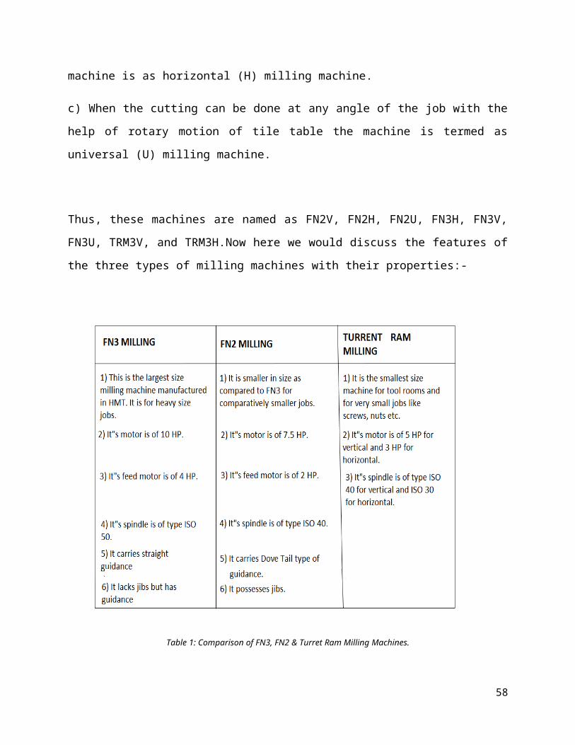
Fig.7: Cylindrical Grinding Machine CNC.
Offers economic solution for cylindrical grinding applications and angular head grinding
applications.
Can be used for grinding of crankshaft journals in automatic cycle with auto positioning.
In process gauge (optional) controls the finished size.
CGM-175 CNC
58
Fig.8: CGM- 175 CNC Grinding Machine.
CGM -225 CNC AH
Fig.9 CGM- 225 CNC AH Grinding Machine.
Different Parts of a CNC Machine:
Angular Wheel Head
59
Fig. 10: Angular Wheel Head.
Tail Stock
Fig. 11: Tail Stock.
InProcess Gauge
60
Fig. 12: Inprocess Gauge.
Hydraulic and Coolant System
Fig. 13: Hydraulic & Coolant System.
Control Panel
61
Fig. 14: Control Panel.
Wheel Head Drive
Fig. 15: Wheel Head Drive.
Touch Probe
62
Fig. 16: Touch Probe.
Pneumatics for InProcess Gauge
Fig. 17: Pneumatics for InProcess Gauge.
Hydraulic and CNC Cylindrical Grinding Machines at a Glance:
63
Table 2: Specifications for Hydraulic Cylindrical Grinding Machines.
Table 3: Specifications for CNC Cylindrical Grinding Machines,
Major Customers:
64
Automobile Sector:
Bajaj Auto
Ashok Leyland
Hero Honda
Honda Motorcycles & Scooters India Ltd.
Mahindra & Mahindra
TELCO
Maruti
Premier Automobiles
Escorts Ltd.
Punjab Tractor
Ford India
LML
Hyundai Motors
Auto- Ancillary:
Kirloskar Toyata Textile Machinery
Shriram Piston & Rings
Munjal Showa
Gabriel India Ltd.
MICO
Cooper Metals
International Tractors
Greaves Cotton Ltd.
SRMT
Sona Steering
Pricol
Kalyani Brakes
General Engineering:
TI Diamonds
AUDCO
65
Assam Carbon Ltd.
BPL
Videocon
Voltas
Godrej
Kirloskar Copeland
Himson Textiles
Bearing Industries:
Timken India
HMT Bearing
SKF Bearing
NRB Bearings
KCI Bearings
NEI
Defense:
Ordnance Factory Ambernath, Khamaria, Ambajari, Katni, Kanpur
V.F & GCF Jabalpur
MSF Ishapore
Nuclear Fuel Complex (NFC)
A.H.Q
Base Repair Depot (BRD)
HAL
Army Base Workshops (ABW)
3.3 Major Achievement in Last Five Years (In House Development):
66
Development of 8 axes CNC CRANK SHAFT JOURNAL AND PIN GRINDING
MACHINE as Import Substitution.
CNC Centre-less grinding machine for grinding bearing race dia. up to 300 mm as import
substitution.
CNC Heavy Duty Vertical spindle reciprocating table surface grinding machine for
grinding locomotive equalizer beams to M/s.CLW, Chittaranjan.
CNC Heavy Duty Cylindrical grinding machine with 3000kg weight capacity, swing
840mm & ABC 3000mm.. Highest value order executed in history of MTA as import
substitution at a price of Rs.330 Lacs for BHEL Haridwar.
CNC Heavy Duty Internal Grinding machine model GI400(SPM) for grinding carbide
bush ID up to 400mm with diamond grinding wheel for M/S Flow Serve, Chennai.
CNC Heavy Duty Double Disc Grinding machine with Shot Gun Type Feeder for
Grinding both faces of Large bearing races as import substitution for M/s Timken,
Jamshedpur.
Robotics loading and un loading of con rods on CNC Double Disc Grinding Machine to
M/S. Mushashi Auto, Gurgaon.
67
Chapter- 4: Conclusion
4.1 Major Work Performed:Though my Training was carried in many important and significant departments in the
Manufacturing Unit yet, I gained expertise in the Manufacturing and Foundry Departments.
In the Manufacturing Department, I acquired a lot of Knowledge of many machines along with
their operational and technical capabilities; those Machines are: Vertical Lathes and Shapers;
Gear Hobbing and Key Making Machines along with other important Machines.
In the Foundry Department I was able to understand the operational points of the Foundry
Department which includes the Pattern shop also very efficiently; I gained a lot of knowledge
there about the different types of Patters, Machines, Equipments, Molding Sands and the
Practices employed during the Operation of the whole Foundry Department.
I'd say that my Training Objectives i.e. to Study about the Operation of the Manufacturing of
Grinding Machines in HMT, Ajmer are met; as I acquired a lot of Theoretical and Practical
Knowledge about my Objectives.
4.2 Five S – Workplace Management:FIVE– S i.e. SEIRI, SEITON, SEISO, SEIKETSU & SHITSUKE are a series of steps taken
for ensuring proper organization.
It aims at NEATNESS, CLEANLINESS, and STANDARDIZATION & DISCIPLINE in an
ORGANIZATION/ workplace for sustained housekeeping & management practices.
5. SHITSUKE (DISCIPLINE)
It means discipline which is called for strict adherence to a system from the present unsystematic
way.
68
4. SEIKETSU (STANDARDIZATION)
It means standard which is needed to maintain 1, 2, 3. It leads to visual management to avoid
mistakes.
3. SEISO (CLEANLINESS)
It deals with the job of thoroughly cleaning the workplace.
2. SEITON (NEATNESS)
It means a place for everything and everything in its place.
1. SEIRI (ORGANISATION)
It is sorting between wanted and unwanted things in a selected area, region or domain
4.3 Recommendations:HMT, Ajmer is a good Manufacturing Unit and like every Unit it has its own Winners and
Losers; In order to be more Productive as well as Employee friendly it needs to employ a Fool
Proof Safety Mechanism for its Employees specially there is a Strict need in the Foundry
Department as the Workers working with the Furnace work without any Safety Gears; another
Recommendation is that since HMT is an Enterprise undertook by The Government of India
(GoI) the Government should invest seriously in the Unit's Infrastructure and Reconditioning as
without any doubt HMT, Ajmer is an Organization which is slowly dying and getting passed its
years of glory and unmatched contribution the Nation, and thereby it's the duty of the Indian
Government to lift up and put back the life in such Organizations which are the Pride of the
Nation.
69


![vtej ftyk nqX/k mRiknd lgdkjh la?k fy vtej...HMT, BEAWAR ROAD, AJMER – 305001 [An ISO 9001:2008 & IS 15000:1998(HACCP) Certified Organization] Email: ajmerdairy@gmail.com (Signed](https://img.dokumen.tips/doc/110x75/5e45814d49a11c5df353adac/vtej-ftyk-nqxk-mriknd-lgdkjh-lak-fy-hmt-beawar-road-ajmer-a-305001-an.jpg)