Embed Size (px)
Citation preview

Grid Based Fuzzy Optimized Routing Protocol for Under Water Sensor Networks
CSE ,MBSTU Defense of Research
Presented By:Kazi Tiomour Rahman TamimID:CE-10018
A S M ZakariaID:CE-10026
Supervised By:
Md. Mahfuz RezaLecturer Dept. Of CSE, MBSTU
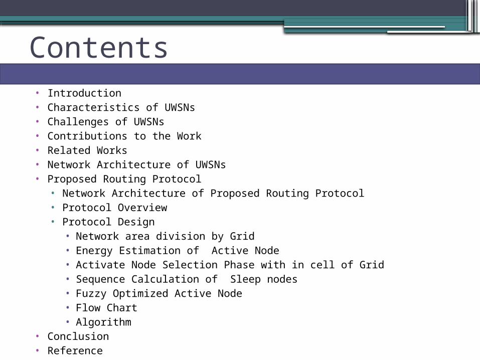
Contents• Introduction• Characteristics of UWSNs• Challenges of UWSNs• Contributions to the Work• Related Works• Network Architecture of UWSNs • Proposed Routing Protocol
• Network Architecture of Proposed Routing Protocol• Protocol Overview• Protocol Design
• Network area division by Grid• Energy Estimation of Active Node • Activate Node Selection Phase with in cell of Grid• Sequence Calculation of Sleep nodes • Fuzzy Optimized Active Node• Flow Chart • Algorithm
• Conclusion• Reference

Introduction
• Oceanographic data collection , water environment monitoring
• hidden knowledge and unknown resources in underwater.
• Marine surveillance, river and sea pollution detection.
• archaeology, seismic and volcanic prediction, oil monitoring.
.

Introduction(Cont…)
• consist of a variable number of sensors.
• Can monitor over a given area.
• Sensor network technology is effective and efficient .
• Sensor nodes can communicate between themselves.
• can sense their residing environment and various activities.

Characteristics of UWSNs
• Low cost• Computation ,sensing, communication , storage • Vehicle tracking , Habitat Monitoring ,Structural
Monitoring • Size small• Low power• Multifunctional• Can easily communicate with shortest distances
• For example • Thermal, Visual, Light, Pressure, Temperature,
Beacon , Humidity etc…

Challenges Of UWSNs
• Low battery power• No real time monitoring • Low bandwidth and high error rates • Limited Storage • Mobility of nodes • High propagation delay • Common errors
• Wireless communication• Node failure are expected
• Scalability to a large number of sensor nodes• Survivability in harsh environments• Experiments are time and space intensive

Contribution to the work
• Grid Based Architecture• Energy consumption • Better Link Expiration time measurement • Fuzzification
• Link Expiration Time(LET)
• Number Of Packets
• Crisp value of Active node (Activeness Ratio)
• Late node are at sleep mode with sequence• Number of packet forwarding according energy of a node

Related protocols
• Sector-based Routing• a node knows its own location• node predicts the location of the destination node• Collect the knowledge of destination location • Delivery ration decreases as node mobile • Each sector node main desire is to send at sink node
• Fuzzy Logic Optimized Vector Protocol • Use 3D architecture• Degrade the average end to end delay occurs at vector
based forwarding • The Geographic Adaptive Fidelity (GAF) protocol
• energy-aware unicast location-based routing protocol• is primarily designed for networks with mobile nodes. The network
region is divided into a virtual grid.

Related protocols(Cont….)
• Focused Beam Routing Protocol• No dynamic angle for drawing beam at each stage.• Use RTS and CTS procedure• Source node must be aware of its own location , its final destination, but not
those of other nodes.• Exists an imaginary line. • Node must relay within imaginary line left and right. • Power level increase if left side no node available to search at right site.
• Parabola Based Routing in Underwater• Use parabola to transmit packets from source to destination.• Best suited node is selected at each time to forward ,to optimize energy. • Hop by hop acknowledgement process has been devised.
• Directional flooding based • Node floods around the network ,forward using link quality.

Network Architecture Of UWSNS
Figure-1 : Network Architecture UWSNs

Network Architecture Of Proposed Routing Protocol
Figure-2:Network Architecture

Network Architecture Of Proposed Routing Protocol(Cont…)
Grid One
Figure-3:Network Architecture(Active Node )

Proposed Routing Protocol(OverView)
Total network is divided into different three dimensional grid
Only one node with in a grid is selected as an Active Node ,remaining nodes will in sleeping mode having their Activeness sequence
Active Node Selection
Measurement of each node’s residual energy within a gridMeasure Link Expiration Time(LET) of each nodeCalculating the Number of packets according to each node’s
residual energyFuzzification of Link Expiration Time(LET) ,Number of Packets to
determine Activeness Ratio(AR).After sorting of Activeness ratio in a (AR) table.The top node of (AR) table will be selected as active node.

Proposed Routing Protocol(Cont….)
• The Active Node will till the number of packet will be zero. when the number of packets of the Active node will zero in sends a request to sleep to the next sequence node.
• When Active node will get go to sleep message from the next sequenced node then it will go to sleep mode and next sequenced node will be Active Node.
• Node Forwarding phase • Active node from one cell will forward packets to the upper
cell active node
•
•

Illustration the number of packets of each node
Total Energy of a node N1,
ET(N1)=ET(N1)-[Ep(N1)+Ea];
Here Ep =Energy Cost Per Packet Send/Receive
Ea =Energy Cost Per Hour Activation
For example
Supposed nodes
Initial Energy
Number of initial packets
Ea Ep Number of packets
send/receive
Activation Hour
ET(Nn)=ET(Nn) -[Ep(Nn)+Ea]
Updated Energy
N1 5j 20 1µj 0.2j 5 5 3.999995=4j
N2 7j 30 1µj 0.2j 4 2 6.2j
N3 6j 25 1µj 0.2j 9 3 4.2j
N4 3j 10 1µj 0.2j 6 1 1.8j

Link Expiration Time Measurement and Architecture
m
monnt
ontmt
2
4
0
2
22
Link Expiration Time Between Nodes:
Where t is the LET , m , n used to calculate Distance between two nodes.

Fuzzification
Very little
little medium
high higher
1
(0,0)Numbers of Packets
3 6 9 12 14 15
Deg
ree o
f m
em
bers
hip
Very low
low moderate many
more
Deg
ree o
f m
em
bers
hip 1
(0,0) 100 200 300 400Link expiration Time(LET)(sec)
The input and output variables are mapped into fuzzy sets using appropriate membership functionMembership Function are:

Fuzzification(cont…)
Activeness Ratio
Very low low
moderate
good best
1
(0,0) 15 40 65 100
Activeness Ratio (%)
Deg
ree o
f m
em
bers
hip
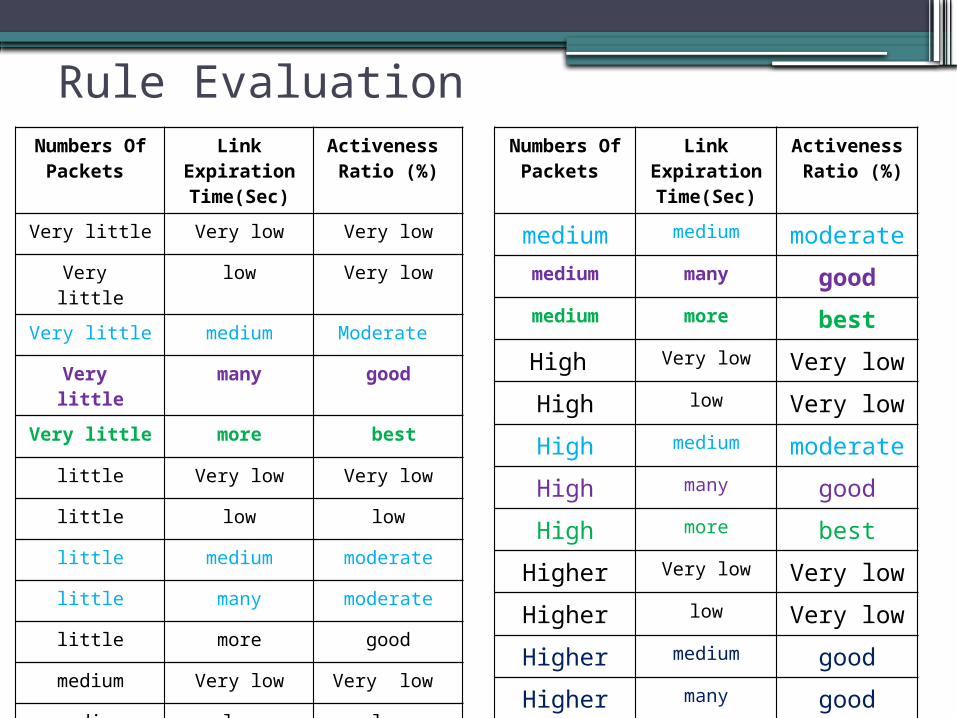
Rule EvaluationNumbers Of
Packets Link
Expiration Time(Sec)
Activeness Ratio (%)
Very little Very low Very low
Very little low Very low
Very little medium Moderate
Very little many good
Very little more best
little Very low Very low
little low low
little medium moderate
little many moderate
little more good
medium Very low Very low
medium low low
Numbers Of Packets
Link Expiration Time(Sec)
Activeness Ratio (%)
medium medium moderatemedium many goodmedium more best
High Very low Very low
High low Very low
High medium moderate
High many good
High more best
Higher Very low Very low
Higher low Very low
Higher medium good
Higher many good
Higher more Moderate

Center Of Gravity(COF) Value Measurement of Activeness
Numbers Of Packets
Link Expiration Time(Sec)
Activeness Ratio (%)
N1(7) 300 55.5%
N2(9) 300 55.9%
N3(14) 400 80.1%
N4(10) 100 42.7%
N5(5) 400 65.8%
Activeness Ratio Table array Of Active
Nodes
N3
N5
N2
N1
N4
Sample COF :

Algorithm for Active NodeSet up initial nodes in the given grid areaAssign nodes with capability of showing their Activeness ratioWhile nodes are being relayed
docheck the Activeness Ratio(AR)
if(current_AR>=Threshold)then ART[i]++;else not enter to the Table array of AR .end if;
End while;

Algorithm for Active Node Selection1) Initialize j,temp True 2) while(true)3) loop j< NoOfNode 4) if ActRatio [j-1] < ActRatio [j] then 5) temp ActRatio [j-1]6) ActRatio [j-1] ActRatio [j]7) ActRatio [j] temp8) end if9) j j+110) end loop11) end while12) return Sequence of ActRatio

Flow Chart of the Proposed Routing protocol(packet forwarding )
start
Enter Node field of a grid
Is Active node exists in upper
grid
yesForward Packet
No
Search at partial upper grid
End
Data Packet
Ensure Forwarding Decision
Assign Active node as forwarding node
Is Active node exists
yes
No Discard the Packet

Simulation and implementation
Figure: Grid Input

Generated Grids

Input within Grids and Activeness Sequence
Figure: (a): Sample Input of LET and No of Packet for 1st Iteration at grid one
Figure: (a): Activeness Ratio and sequence of each node at grid one
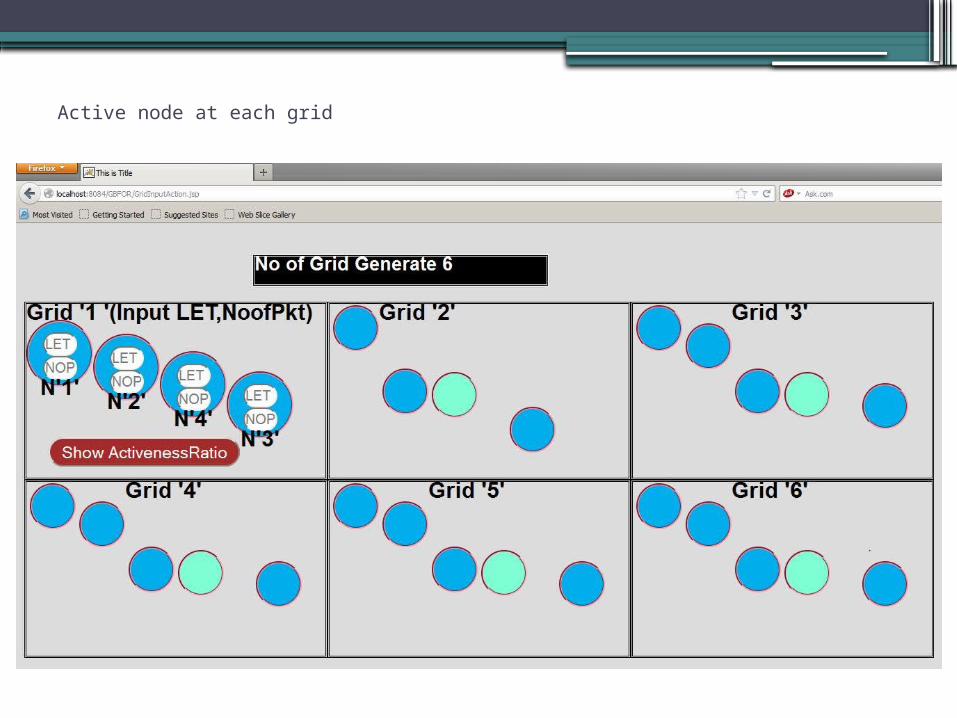
Active node at each grid

More iterations
Figure: Input LET ,NOP Figure: Activeness Ratio

ghh
Fuzzy Viewer
Simulation With Fuzzy Inference Engine

Fuzzy Input(Number Of Packets )

Fuzzy Input(Link Expiration Time )

Fuzzy Output(Activeness Ratio)

Fuzzy Rules

Fuzzy Rules Viewer

Fuzzy Surface Viewer

Performance Evaluation Performance metrics:
Network Life Time Total Energy Consumption Average End to End Delay

Performance Evaluation(cont…)
(a)Total energy consumption of FBR with different node mobility (b)Total energy consumption of GBFOR protocol with different node mobility
Figure 8: Comparison of total energy consumption of GBFOR protocol with FBR protocol

Performance Evaluation(Cont…)
Fig:(a)Comparison of network life time between GBFOR and FBR Fig:(a)Comparison of end to end delay between GBFOR and FBR

Conclusion and Future Plan
GBFOR protocol has been designed keeping in mind the challenges involved in energy consumptions and REQ,RES procedure in underwater conditions. As fuzzy optimized easy to work with different quality nodes and network life time high. In the future, we plan to adopt detour mechanism to avoid the void of zone and to develop better mobility handle method.

References[1]. Josep Miquel Jornet, Milica Stojanovic, Michele Zorzi. “Focused Beam Routing Protocol for Underwater Acoustic Networks”,WUWNet’08, September 15, 2008, San Francisco, CA.
[2]. Md.Asraf Uddin and Mamun-or-Rashid, “Link Expiration Time Aware Routing Protocol for UWSNs”, Hindawi Publishing Corporation volume:2013, Article ID6252,http://dx.doi.org/10.1155/2013/625274.
[3]. Daeyoup Hwang, Dongkyun Kim. “DFR: Directional Flooding Based Routing Protocol for Underwater Sensor Networks”,
978-1-4244-2620-1/08 ©2008 IEEE
[4]. Reza Javidan,Hamideh Rafiee.” A New Energy Efficient and Depth based routing protocol for underwater sensor network”
British Journal of Science January 2013,vol.8(1).
[5]. Z. Zhou, J.-H. Cui, and S. Zhou. Localization for large-scale underwater sensor networks. UCONN CSE Technical Report: UbiNet-
TR06-,http://www.cse.uconn.edu/jcui/publications.html, Dec. 2006.

References(cont…)[6]. Sohrab Sarafiabadi , Sara Parvaneh,SeyedKeyvan
Babai,Yashar Sarafiabadi .“Fuzzy Logic Optimized Vector Protocol for Underwater Sensor Network” , IPCSIT vol. 41 (2012) © (2012) IACSIT Press, Singapore
[7]. Sanjay K. Dhurandher, Mohammad S. Obaidat .” Optimizing
Energy through Parabola Based Routing in Underwater sensor network“,IEEE 2011.
[8]. Ian F. Akyildiz, Georgia Institute of Technology, USA.”Wireless sensor network”.
[9]. P.S.Hiremath, Shrihari M.Joshi .” Energy Efficient Routing Protocol with Adap Fuzzy Threshold Energy for MANETs ”.IJCNWC), ISSN: 2250-3501 Vol.2, No.3, June 2012.
[10]. Partha Sarathi Banerjee, Paulchoudhury, S. R. Bhadra Chaudhuri .” Fuzzy Membership Function in a Trust Based AODV for MANET ”. October 2013 i (http://www.mecs-
press.org/) DOI: 10.5815/ijcnis.2013.12.04.
[11]. Sinchan Roychowdhury,ChiranjibPatra “The Geographic Adaptive Fidelity (GAF) protocol (Xu et al. 2001)”.


![[OER] Cisco IOS Optimized Edge Routing Configuration](https://img.dokumen.tips/doc/110x75/5532f4c74a7959ae4b8b479d/oer-cisco-ios-optimized-edge-routing-configuration.jpg)